WO2014073377A1 - 遠心回転機械のインペラ、遠心回転機械 - Google Patents
遠心回転機械のインペラ、遠心回転機械 Download PDFInfo
- Publication number
- WO2014073377A1 WO2014073377A1 PCT/JP2013/078691 JP2013078691W WO2014073377A1 WO 2014073377 A1 WO2014073377 A1 WO 2014073377A1 JP 2013078691 W JP2013078691 W JP 2013078691W WO 2014073377 A1 WO2014073377 A1 WO 2014073377A1
- Authority
- WO
- WIPO (PCT)
- Prior art keywords
- impeller
- disk
- blade
- rotating machine
- separated
- Prior art date
- Legal status (The legal status is an assumption and is not a legal conclusion. Google has not performed a legal analysis and makes no representation as to the accuracy of the status listed.)
- Ceased
Links
Images


Classifications
-
- F—MECHANICAL ENGINEERING; LIGHTING; HEATING; WEAPONS; BLASTING
- F04—POSITIVE - DISPLACEMENT MACHINES FOR LIQUIDS; PUMPS FOR LIQUIDS OR ELASTIC FLUIDS
- F04D—NON-POSITIVE-DISPLACEMENT PUMPS
- F04D29/00—Details, component parts, or accessories
- F04D29/26—Rotors specially for elastic fluids
- F04D29/28—Rotors specially for elastic fluids for centrifugal or helico-centrifugal pumps for radial-flow or helico-centrifugal pumps
- F04D29/284—Rotors specially for elastic fluids for centrifugal or helico-centrifugal pumps for radial-flow or helico-centrifugal pumps for compressors
-
- F—MECHANICAL ENGINEERING; LIGHTING; HEATING; WEAPONS; BLASTING
- F04—POSITIVE - DISPLACEMENT MACHINES FOR LIQUIDS; PUMPS FOR LIQUIDS OR ELASTIC FLUIDS
- F04D—NON-POSITIVE-DISPLACEMENT PUMPS
- F04D17/00—Radial-flow pumps, e.g. centrifugal pumps; Helico-centrifugal pumps
- F04D17/08—Centrifugal pumps
- F04D17/10—Centrifugal pumps for compressing or evacuating
- F04D17/12—Multi-stage pumps
- F04D17/122—Multi-stage pumps the individual rotor discs being, one for each stage, on a common shaft and axially spaced, e.g. conventional centrifugal multi- stage compressors
-
- F—MECHANICAL ENGINEERING; LIGHTING; HEATING; WEAPONS; BLASTING
- F04—POSITIVE - DISPLACEMENT MACHINES FOR LIQUIDS; PUMPS FOR LIQUIDS OR ELASTIC FLUIDS
- F04D—NON-POSITIVE-DISPLACEMENT PUMPS
- F04D29/00—Details, component parts, or accessories
- F04D29/18—Rotors
- F04D29/22—Rotors specially for centrifugal pumps
- F04D29/24—Vanes
- F04D29/242—Geometry, shape
-
- F—MECHANICAL ENGINEERING; LIGHTING; HEATING; WEAPONS; BLASTING
- F04—POSITIVE - DISPLACEMENT MACHINES FOR LIQUIDS; PUMPS FOR LIQUIDS OR ELASTIC FLUIDS
- F04D—NON-POSITIVE-DISPLACEMENT PUMPS
- F04D29/00—Details, component parts, or accessories
- F04D29/26—Rotors specially for elastic fluids
- F04D29/28—Rotors specially for elastic fluids for centrifugal or helico-centrifugal pumps for radial-flow or helico-centrifugal pumps
- F04D29/281—Rotors specially for elastic fluids for centrifugal or helico-centrifugal pumps for radial-flow or helico-centrifugal pumps for fans or blowers
- F04D29/282—Rotors specially for elastic fluids for centrifugal or helico-centrifugal pumps for radial-flow or helico-centrifugal pumps for fans or blowers the leading edge of each vane being substantially parallel to the rotation axis
-
- F—MECHANICAL ENGINEERING; LIGHTING; HEATING; WEAPONS; BLASTING
- F04—POSITIVE - DISPLACEMENT MACHINES FOR LIQUIDS; PUMPS FOR LIQUIDS OR ELASTIC FLUIDS
- F04D—NON-POSITIVE-DISPLACEMENT PUMPS
- F04D29/00—Details, component parts, or accessories
- F04D29/26—Rotors specially for elastic fluids
- F04D29/28—Rotors specially for elastic fluids for centrifugal or helico-centrifugal pumps for radial-flow or helico-centrifugal pumps
- F04D29/30—Vanes
-
- F—MECHANICAL ENGINEERING; LIGHTING; HEATING; WEAPONS; BLASTING
- F04—POSITIVE - DISPLACEMENT MACHINES FOR LIQUIDS; PUMPS FOR LIQUIDS OR ELASTIC FLUIDS
- F04D—NON-POSITIVE-DISPLACEMENT PUMPS
- F04D29/00—Details, component parts, or accessories
- F04D29/18—Rotors
- F04D29/22—Rotors specially for centrifugal pumps
- F04D29/2238—Special flow patterns
- F04D29/2255—Special flow patterns flow-channels with a special cross-section contour, e.g. ejecting, throttling or diffusing effect
-
- F—MECHANICAL ENGINEERING; LIGHTING; HEATING; WEAPONS; BLASTING
- F04—POSITIVE - DISPLACEMENT MACHINES FOR LIQUIDS; PUMPS FOR LIQUIDS OR ELASTIC FLUIDS
- F04D—NON-POSITIVE-DISPLACEMENT PUMPS
- F04D29/00—Details, component parts, or accessories
- F04D29/26—Rotors specially for elastic fluids
- F04D29/28—Rotors specially for elastic fluids for centrifugal or helico-centrifugal pumps for radial-flow or helico-centrifugal pumps
- F04D29/281—Rotors specially for elastic fluids for centrifugal or helico-centrifugal pumps for radial-flow or helico-centrifugal pumps for fans or blowers
-
- F—MECHANICAL ENGINEERING; LIGHTING; HEATING; WEAPONS; BLASTING
- F05—INDEXING SCHEMES RELATING TO ENGINES OR PUMPS IN VARIOUS SUBCLASSES OF CLASSES F01-F04
- F05D—INDEXING SCHEME FOR ASPECTS RELATING TO NON-POSITIVE-DISPLACEMENT MACHINES OR ENGINES, GAS-TURBINES OR JET-PROPULSION PLANTS
- F05D2240/00—Components
- F05D2240/20—Rotors
- F05D2240/30—Characteristics of rotor blades, i.e. of any element transforming dynamic fluid energy to or from rotational energy and being attached to a rotor
- F05D2240/301—Cross-sectional characteristics
-
- F—MECHANICAL ENGINEERING; LIGHTING; HEATING; WEAPONS; BLASTING
- F05—INDEXING SCHEMES RELATING TO ENGINES OR PUMPS IN VARIOUS SUBCLASSES OF CLASSES F01-F04
- F05D—INDEXING SCHEME FOR ASPECTS RELATING TO NON-POSITIVE-DISPLACEMENT MACHINES OR ENGINES, GAS-TURBINES OR JET-PROPULSION PLANTS
- F05D2240/00—Components
- F05D2240/20—Rotors
- F05D2240/30—Characteristics of rotor blades, i.e. of any element transforming dynamic fluid energy to or from rotational energy and being attached to a rotor
- F05D2240/306—Characteristics of rotor blades, i.e. of any element transforming dynamic fluid energy to or from rotational energy and being attached to a rotor related to the suction side of a rotor blade
-
- F—MECHANICAL ENGINEERING; LIGHTING; HEATING; WEAPONS; BLASTING
- F05—INDEXING SCHEMES RELATING TO ENGINES OR PUMPS IN VARIOUS SUBCLASSES OF CLASSES F01-F04
- F05D—INDEXING SCHEME FOR ASPECTS RELATING TO NON-POSITIVE-DISPLACEMENT MACHINES OR ENGINES, GAS-TURBINES OR JET-PROPULSION PLANTS
- F05D2250/00—Geometry
- F05D2250/70—Shape
Definitions
- a centrifugal rotating machine such as a centrifugal compressor
- a flow in a direction different from the main flow that is, a secondary flow
- the low energy fluid accumulates in the flow path of the impeller, and the accumulated portion is in a state where the velocity and energy of the fluid are largely lost. For this reason, such a secondary flow is one of the factors that degrade the performance of the centrifugal rotating machine.
- Patent Document 1 discloses an impeller of a centrifugal compressor that improves the performance by suppressing a secondary flow from the pressure surface side of the blade to the suction surface side of the impeller. Specifically, in this impeller, by providing riblets along the main flow from the side wall surface in the flow path, the boundary layer flow in the side wall surface flows from the pressure surface of the blade to the suction surface across the flow path. It is preventing.
- the present invention provides an impeller for a centrifugal rotating machine capable of further improving the performance by suppressing the secondary flow toward the direction away from the disk on the rear side in the rotation direction on the suction surface side.
- the impeller of the centrifugal rotating machine includes a disk having a disc shape centered on an axis, a front edge through which fluid flows in, and a rear edge through which fluid flows, and faces the direction of the axis. And a plurality of blades provided on the surface at intervals in the circumferential direction. The blade rises from the disk between the front edge and the rear edge of the blade, and continues from the first part, the first part being inclined rearward in the rotational direction as the blade is separated from the disk. And a second portion that inclines toward the front side in the rotational direction as it moves away.
- the first portion of the blade is inclined to the rear side in the rotational direction, so that the first portion swells rearward in the rotational direction.
- the secondary flow that occurs on the rear side in the rotation direction and flows away from the disk is pressed toward the first portion swelled on the rear side. Therefore, at the point where the secondary flow comes into contact with the first part, the secondary flow becomes a tangential component at this point and a normal direction component that is a component that pushes the secondary flow against the first part perpendicular to the tangential component. Is broken down.
- the secondary flow does not contact the first part, and the component in the normal direction becomes zero.
- a part of the secondary flow is directed in the normal direction and the rest is directed in the tangential direction, so that all of the secondary flow is not directed to a position away from the disk.
- the second portion of the blade is inclined forward in the rotational direction, it is possible to receive a pressing force of the fluid from the forward side in the rotational direction. For this reason, even if the 1st part inclines to the back side of a rotation direction, the pressing force from a fluid can be used effectively and compression efficiency will not be reduced.
- the impeller of the centrifugal rotating machine is located on the front edge side of the first part, rises from the disk, and inclines toward the front side in the rotation direction as it is separated. And a fourth portion that is located closer to the front edge than the second portion, continues from the third portion, and inclines toward the front side in the rotational direction as it is separated from the disk. .
- the impeller of the centrifugal rotating machine is located on the rear edge side of the first part, rises from the disk, and inclines toward the rear side in the rotational direction as it moves away. And a sixth portion that is located closer to the trailing edge than the second portion, continues from the fifth portion, and inclines toward the rear side in the rotational direction as it is separated from the disk. .
- the impeller of the centrifugal rotating machine is located on the trailing edge side with respect to the fifth portion, rises from the disk, and inclines toward the front side in the rotational direction as the disk is separated.
- a centrifugal rotating machine includes a rotating shaft that rotates about an axis, an impeller of the centrifugal rotating machine that is fitted around the rotating shaft and rotates together, and the rotating shaft.
- a casing that rotatably supports the casing and covers the impeller from the outer peripheral side.
- the blade of the impeller since the blade of the impeller includes the first part and the second part, a part of the secondary flow at a contact point between the blade and the secondary flow generated on the rear side in the rotation direction. Is directed in the normal direction of the contact point and the rest is directed in the tangential direction, so that all of the secondary flow does not go to a position away from the disk. Moreover, the pressing force of the fluid from the front side of the rotation direction can be received by the second portion.
- the blade includes the first portion and the second portion, thereby suppressing the secondary flow that flows away from the disk on the rear side in the rotation direction, and from the fluid. It is possible to effectively use the pressing force of and to improve the performance.
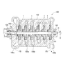
- FIG. 1 is an overall schematic diagram showing a centrifugal compressor according to an embodiment of the present invention. It is a perspective view which shows a partially broken impeller in the centrifugal compressor according to the embodiment of the present invention. It is a meridional view showing the main part of the impeller in the centrifugal compressor according to the embodiment of the present invention.
- FIG. 4 is a cross-sectional view of an impeller blade in the centrifugal compressor according to the embodiment of the present invention, and shows a cross section taken along line X1-X1 of FIG.
- FIG. 4 is a cross-sectional view of an impeller blade in the centrifugal compressor according to the embodiment of the present invention, showing a cross section taken along line X2-X2 of FIG.
- FIG. 4 is a cross-sectional view of an impeller blade in the centrifugal compressor according to the embodiment of the present invention, showing an X3-X3 cross section of FIG. 3.
- FIG. 4 is a cross-sectional view of an impeller blade in the centrifugal compressor according to the embodiment of the present invention, and shows an X4-X4 cross section of FIG. 3.
- FIG. 4 is a cross-sectional view of an impeller blade in the centrifugal compressor according to the embodiment of the present invention, showing a cross section taken along the line X5-X5 in FIG.
- FIG. 4 is a cross-sectional view of an impeller blade in the centrifugal compressor according to the embodiment of the present invention, showing a cross section taken along line X6-X6 in FIG. It is sectional drawing of the blade of the impeller in the centrifugal compressor which concerns on embodiment of this invention, Comprising: It is a figure which shows the direction of the secondary flow in FIG. 4C.
- the centrifugal compressor 100 includes a casing 102, a rotary shaft 101 that is pivotally supported inside the casing 102 via a journal bearing 103 and a thrust bearing 104, and is rotatable around an axis O.
- An impeller 1 that is externally fitted to the rotary shaft 101 along the axis O direction is provided.
- the centrifugal compressor 100 uses the centrifugal force of the impeller 1 that rotates together with the rotating shaft 101 to allow the fluid F0 supplied from the suction port 105c formed in the casing 102 to flow from the upstream flow path 105a to the downstream flow. It distributes in a stepwise manner to the path 105b. During distribution, the fluid F0 is pressurized and discharged from the discharge port 105d.
- the impeller 1 is externally fitted to the rotation shaft 101 and rotates in the rotation direction R about the axis O together with the rotation shaft 101.
- a plurality (six) of impellers 1 are provided to constitute a multistage centrifugal compressor.
- each impeller 1 includes a disk 3 having a substantially disk shape when viewed in the direction of the axis O, a plurality of blades 4 provided on the disk 3, and a cover 5 that covers these blades 4 from the direction of the axis O. It has.
- the disk 3 has a small diameter end surface facing the first direction in the axis O direction, a large diameter end surface facing the second direction side, and these two end surfaces are second from the first direction side in the axis O direction.
- the curved surface 3a that gradually increases in diameter toward the direction side, it is a member that has a substantially disc shape when viewed in the direction of the axis O, and has a generally umbrella shape as a whole.
- a through hole 3b is formed on the inner side in the radial direction of the disk 3 so as to penetrate the disk 3 in the axis O direction.
- the blades 4 are a plurality of members that are provided at regular intervals in the circumferential direction of the axis O, that is, in the rotation direction R so as to rise from the curved surface 3a of the disk 3 to the first direction side in the axis O direction.
- Each of the plurality of blades 4 is formed so as to bend toward the rear side in the rotation direction R from the inner side to the outer side in the radial direction of the disk 3, and the surface facing the front side in the rotation direction R is a pressure.
- the surface that faces the rear side in the rotation direction R is a suction surface.
- the cover 5 is a member provided integrally with these blades 4 so as to cover the plurality of blades 4 from the first direction side in the axis O direction, and is gradually expanded in diameter toward the second direction side in the axis O direction. It has an umbrella shape. That is, in this embodiment, the impeller 1 is a closed impeller having a cover 5.
- the space surrounded by the two adjacent blades 4, the disk 3, and the cover 5 becomes the impeller flow path FC in which the fluid F0 can flow from the radially inner side to the outer side.
- the fluid F0 is taken into the impeller channel FC from the first direction side of the impeller 1 in the direction of the axis O, that is, the front edge 4a side of the blade 4, and the fluid F0 is discharged from the rear edge 4b side of the blade 4 that is radially outside. Is done.
- the blade 4 has a part B, a part A, a part C, and a part D in order from the front edge 4a side to the rear edge 4b side.
- the portion A is a first portion 10A formed at a position close to the disk 3 on the most front edge 4a side of the blade 4 and extending toward the disk 3 so as to be spaced apart from the disk.
- Two parts 11A That is, the first portion 10A and the second portion 11A are formed continuously with a virtual line L serving as a midway position in the rising direction of the blade 4 (in this embodiment, the center position in the rising direction of the blade 4) as a boundary.
- the first portion 10A has a lean angle ⁇ that inclines toward the rear side in the rotation direction R in the blade 4 and rises from the disk 3 and is smoothly curved as it moves away.
- the second portion 11A is continuous from the first portion 10A toward the cover 5, and smoothly curves and extends toward the front side in the rotational direction R as the distance from the disk 3 increases.
- FIGS. 4B, 4C, and 4D an example of the formation positions of the first portion 10A and the second portion 11A is shown in FIGS. 4B, 4C, and 4D. That is, in the present embodiment, the first portion 10A and the second portion 11A are formed at positions that are 15% to 65% from the front edge 4a on the meridian surface of the impeller 1, for example.
- the first portion 10A has a maximum lean angle ⁇ at a position of 40% while the lean angle ⁇ gradually increases from the front edge 4a side, and the lean angle ⁇ gradually increases again toward the rear edge 4b side. Decrease. That is, the first portion 10A of the blade 4 is most inclined to the rear side in the rotation direction R at a position that is 40% on the meridian plane.
- the position most inclined to the rear side is not limited to a position that is 40% on the meridian plane, and the numerical value of 40% is an example.
- the second portion 11A gradually increases in degree of curvature from the front edge 4a side, the degree of curvature becomes maximum at a position of 40%, and the degree of curvature gradually decreases toward the rear edge 4b again. . That is, the second portion 11A of the blade 4 is most inclined forward in the rotational direction R at a position that is 40% on the meridian plane.
- the position most inclined forward is not limited to a position that is 40% on the meridian plane, and the numerical value of 40% is an example.
- the part B is a part located closer to the front edge 4a of the blade 4 than the part A, and the third part 10B formed at a position near the disk 3 continuously to the disk 3 and the virtual line L as a boundary.
- the third portion 10B includes a fourth portion 11B extending continuously from the disk.
- the fourth portion 11B is not inclined from the connection portion with the third portion 10B on the front edge 4a side of the blade 4 than the second portion 11A, and extends straightly from the third portion 10B. It extends. That is, the fourth portion 11B is inclined forward in the rotational direction R.
- the third portion 10B and the fourth portion 11B are, for example, from a position that is 0% on the meridian surface of the impeller 1 to a position on the front edge 4a side of the portion A, that is, in the vicinity of the front edge 4a. Is formed.
- the part C is a part located on the rear edge 4b side of the blade 4 with respect to the part B, and the fifth part 10C formed at a position near the disk 3 continuously to the disk 3 and the virtual line L as a boundary.
- the fifth portion 10C is provided with a sixth portion 11C extending continuously from the disk.
- the fifth portion 10C rises from the disk 3 with a lean angle ⁇ that inclines toward the rear side in the rotational direction R on the rear edge 4b side of the blade 4 relative to the first portion 10A. And it is provided so as to extend linearly as the distance from the disk 3 increases.
- the sixth portion 11C is not inclined from the connection portion with the fifth portion 10C on the rear edge 4b side of the blade 4 than the second portion 11A, and extends straightly from the fifth portion 10C. It extends, that is, it is inclined rearward in the rotational direction R.
- FIG. 4E an example of the formation positions of the fifth portion 10C and the sixth portion 11C is shown in FIG. 4E. That is, in the present embodiment, the fifth portion 10C and the sixth portion 11C are formed, for example, from the rear edge 4b side of the portion A to a position that is 85% on the meridian surface of the impeller 1.
- the part D is a part located further on the rear edge 4b side of the blade 4 than the part C.
- the part D is continuous with the disk 3 and formed at a position near the disk 3 and the imaginary line L as a boundary.
- the seventh portion 10D includes an eighth portion 11D extending continuously from the disk.
- the seventh portion 10D has a lean angle ⁇ such that the seventh portion 10D is inclined further to the front side in the rotational direction R on the rear edge 4b side of the blade 4 than the fifth portion 10C, like the front edge 4a. And is provided to extend linearly as the distance from the disk 3 increases.
- the eighth portion 11D is not inclined from the connecting portion with the seventh portion 10D on the further rear edge 4b side of the blade 4 than the sixth portion 11C, and extends straightly from the seventh portion 10D. That is, it is inclined to the front side in the rotation direction R like the front edge 4a.
- FIG. 4F an example of the formation positions of the seventh portion 10D and the eighth portion 11D is shown in FIG. 4F. That is, in the present embodiment, the seventh portion 10D and the eighth portion 11D are formed, for example, from the rear edge 4b side of the portion C to a position that is 100% on the meridian surface of the impeller 1, that is, in the vicinity of the rear edge 4b. ing.
- At least one portion between the front edge 4 a and the rear edge 4 b is inclined to the rear side in the rotation direction R on the disk 3 side from the virtual line L.
- the blade 4 includes a first portion 10A that is inclined rearward in the rotation direction R. Accordingly, the first portion 10A is arranged so as to swell rearward in the rotation direction R. Therefore, when the secondary flow F flowing along the suction surface is generated so as to be separated from the disk 3 as shown in FIG. The next flow F is pressed against the first portion 10A.
- the secondary flow F is divided into a tangential component F 1 at the point A and a normal component F 2 orthogonal to the tangential component F 1 at the point A on the suction surface that contacts the first portion 10A. Disassembled.
- the normal direction component F 2 is a component that presses the secondary flow F against the first portion 10.
- the blade 4 since the blade 4 includes the second portion 11A that is inclined forward in the rotation direction R, the blade 4 can receive the pressing force of the fluid F0 on the pressure surface. For this reason, even if 10 A of 1st parts incline to the back side of the rotation direction R, compression efficiency will not be reduced.
- the blade 4 includes the third portion 10B and the fourth portion 11B that are inclined forward in the rotational direction R at a position of 0% on the meridian plane, thereby introducing the fluid F0 into the flow path FC. At that time, the pressing force of the fluid F0 on the pressure surface can be reliably received by the blade 4 on the front edge 4a side of the blade 4, so that the fluid F0 can be more efficiently compressed.
- the blade 4 is between the front edge 4a and the rear edge 4b, the first portion 10A is inclined rearward in the rotation direction R, and the second portion 11A is the rotation direction. Inclined to the front side of R. For this reason, the secondary flow F flowing away from the disk 3 on the rear side in the rotation direction R can be suppressed, and the position away from the disk 3 on the rear side in the rotation direction R of the blade 4, that is, in the cover 5. Accumulation of low-energy fluid at adjacent positions can be suppressed. Further, on the pressure surface, this force can be effectively utilized by receiving the pressing force from the fluid F0, and the compression efficiency can be maintained while the secondary flow F is suppressed, and the performance can be improved.
- the embodiment of the present invention has been described in detail above, some design changes can be made without departing from the technical idea of the present invention.
- at least one portion between the front edge 4a and the rear edge 4b of the blade is inclined to the rear side in the rotation direction R, and the first portion 10A is continuously inclined to the front side in the rotation direction R.
- the second part 11A is just to have the second part 11A.
- the inclination direction and shape of the third portion 10B, the fourth portion 11B, the fifth portion 10C, the sixth portion 11C, the seventh portion 10D, and the eighth portion 11D are not limited to the above-described embodiments. Further, they may be provided so as not to be inclined in the rotation direction R but to be arranged on the virtual line L1.
- the first portion 10A and the second portion 11A are provided in a curved shape, but may be provided in a linear shape.
- the impeller 1 is described as a closed impeller. However, an open impeller without the cover 5 may be used.
- centrifugal compressor 100 is not limited to a multistage compressor, and the blade 4 of the impeller 1 described above can also be applied to a single stage compressor.
- the centrifugal rotating machine is not limited to a centrifugal compressor, and may be a blower, a centrifugal pump, or the like.
- the blade includes the first portion and the second portion, thereby suppressing the secondary flow that flows away from the disk on the rear side in the rotation direction, and from the fluid. It is possible to effectively use the pressing force of and to improve the performance.
Landscapes
- Engineering & Computer Science (AREA)
- Mechanical Engineering (AREA)
- General Engineering & Computer Science (AREA)
- Physics & Mathematics (AREA)
- Geometry (AREA)
- Structures Of Non-Positive Displacement Pumps (AREA)
Abstract
軸線を中心とした円盤状をなすディスク(3)の軸線の方向を向く面に周方向に間隔をあけて複数のブレード(4)が設けられた遠心回転機械のインペラにおいて、ブレード(4)は、ブレード(4)における前縁と後縁との間に、ディスク(3)から立ち上がり、かつ離間するに従って回転方向Rの後方側に傾斜する第一部分(10A)と、第一部分(10A)から連続し、ディスク(3)から離間するに従って回転方向Rの前方側に傾斜する第二部分(11A)とを備える。
Description
本発明は、遠心圧縮機、送風機、遠心ポンプ等の遠心回転機械に用いられるインペラに関する。
本願は、2012年11月6日に日本に出願された特願2012-244784号について優先権を主張し、その内容をここに援用する。
本願は、2012年11月6日に日本に出願された特願2012-244784号について優先権を主張し、その内容をここに援用する。
遠心圧縮機等の遠心回転機械においては、ヘッドの向上、作動範囲の拡大等による性能向上が市場より求められており、これに対して様々な対策がなされている。
ここで、遠心回転機械に用いられるインペラの流路内において、主流とは異なる方向に向かう流れ、即ち二次流れが発生することがある。この二次流れによっては、低エネルギー流体がインペラの流路内に蓄積してしまい、この蓄積部分は流体の速度及びエネルギーが大きく欠損した状態となる。このため、このような二次流れが遠心回転機械の性能を低下させてしまう要因の一つとなっている。
ここで、遠心回転機械に用いられるインペラの流路内において、主流とは異なる方向に向かう流れ、即ち二次流れが発生することがある。この二次流れによっては、低エネルギー流体がインペラの流路内に蓄積してしまい、この蓄積部分は流体の速度及びエネルギーが大きく欠損した状態となる。このため、このような二次流れが遠心回転機械の性能を低下させてしまう要因の一つとなっている。
特許文献1には、インペラにおけるブレードの圧力面側から負圧面側に向かう二次流れを抑制して、性能向上を図った遠心圧縮機のインペラが開示されている。具体的にはこのインペラでは、流路における側壁面から主流の流れに沿ってリブレットを設けることで、側壁面における境界層流れがブレードの圧力面から負圧面に流路を横切って流通することを防止している。
しかしながら、回転機械のインペラにおいては、特許文献1に開示されたものとは異なる二次流れが発生することがある。この二次流れは、各流路において負圧面側でディスクから離間するように軸線の方向に向かう流れである。これにより負圧面側であってディスクから離間した位置(クローズドインペラであればカバーの直下)に低エネルギー流体が蓄積され、回転機械の性能低下の要因となっている。
本発明は、負圧面側となる回転方向の後方側でディスクから離間する方向に向かう二次流れを抑制して、さらなる性能向上が可能な遠心回転機械のインペラを提供する。
本発明の第一の態様に係る遠心回転機械のインペラは、軸線を中心とした円盤状をなすディスクと、流体が流入する前縁と流出する後縁とを有し、前記軸線の方向を向く面に周方向に間隔をあけて設けられた複数のブレードとを備える。前記ブレードは、該ブレードにおける前記前縁と前記後縁との間に、前記ディスクから立ち上がり、かつ離間するに従って回転方向の後方側に傾斜する第一部分と、該第一部分から連続し、前記ディスクから離間するに従って前記回転方向の前方側に傾斜する第二部分とを備える。
このようなインペラによると、ブレードの第一部分が、回転方向の後方側に傾斜していることで、この第一部分が回転方向の後方側に膨らむよう配置されている。このため、回転方向の後方側で生じ、ディスクから離間するように流れる二次流れは、この後方側に膨らんだ第一部分に向かって押し付けられる。よって、二次流れが第一部分に接触する点において、この点における接線方向成分と、この接線方向成分に直交して二次流れを第一部分に押し付ける成分である法線方向成分とに二次流れは分解される。ここで、仮に第一部分が回転方向の後方側に傾斜していない場合には、二次流れは第一部分に接触せず、法線方向の成分がゼロとなるため、二次流れの全てがディスクから離間する方向に向かう。本発明の態様によれば、二次流れの一部が法線方向に向かい、残りが接線方向に向かうため、二次流れの全てがディスクから離間する位置へ向かうことがない。また、ブレードの第二部分が回転方向の前方側に傾いていることで、回転方向の前方側からの流体の押圧力を受けることができる。このため、第一部分が回転方向の後方側に傾斜していても、流体からの押圧力を有効に利用することができ、圧縮効率を低下させてしまうことがない。
本発明の第二の態様によれば、遠心回転機械のインペラは、前記第一部分よりも前記前縁側に位置し、前記ディスクから立ち上がり、かつ離間するに従って前記回転方向の前方側に傾斜する第三部分と、前記第二部分よりも前記前縁側に位置し、前記第三部分から連続し、前記ディスクから離間するに従って前記回転方向の前方側に傾斜する第四部分とをさらに備えていてもよい。
このような第二部分、第三部分、第四部分によって、ブレードの前縁側では回転方向の前方側からの流体の押圧力を確実に受けることができるとともに、第一部分によって回転方向の後方側においてディスクから離間する方向への二次流れを抑制することができるため、さらなる性能向上が可能である。
本発明の第三の態様によれば、遠心回転機械のインペラは、前記第一部分よりも前記後縁側に位置し、前記ディスクから立ち上がり、かつ離間するに従って前記回転方向の後方側に傾斜する第五部分と、前記第二部分よりも前記後縁側に位置し、前記第五部分から連続し、前記ディスクから離間するに従って前記回転方向の後方側に傾斜する第六部分とをさらに備えていてもよい。
本発明の第四の態様によれば、遠心回転機械のインペラは、前記第五部分よりも前記後縁側に位置し、前記ディスクから立ち上がり、かつ離間するに従って前記回転方向の前方側に傾斜する第七部分と、前記第六部分よりも前記後縁側に位置し、前記第七部分から連続し、前記ディスクから離間するに従って前記回転方向の前方側に傾斜する第八部分とをさらに備えていてもよい。
本発明の第五の態様によれば、遠心回転機械は、軸線を中心に回転する回転軸と、前記回転軸に外嵌されて共に回転する上記の遠心回転機械のインペラと、前記回転軸を回転可能に支持するとともに、前記インペラを外周側から覆うケーシングとを備える。
このような遠心回転機械によると、インペラのブレードが第一部分及び第二部分を備えていることで、ブレードと回転方向の後方側で生じる二次流れとの接触点において、二次流れの一部が接触点の法線方向に向かい、残りが接線方向に向かうため、二次流れの全てがディスクから離間する位置へ向かうことがない。また、第二部分によって回転方向の前方側からの流体の押圧力を受けることができる。
上述したインペラ、及び遠心回転機械によると、ブレードが第一部分と第二部分とを備えていることで、回転方向の後方側でディスクから離間するように流れる二次流れを抑制するとともに、流体からの押圧力を有効に利用でき、性能向上が可能となる。
〔第一実施形態〕
以下、本発明の実施形態に係る遠心圧縮機(遠心回転機械)100について説明する。
図1に示すように、遠心圧縮機100は、ケーシング102と、ケーシング102の内部にジャーナル軸受103及びスラスト軸受104を介して軸支され、軸線O回りに回転可能とされた回転軸101と、回転軸101に軸線O方向に並んで外嵌されたインペラ1とを備えている。
以下、本発明の実施形態に係る遠心圧縮機(遠心回転機械)100について説明する。
図1に示すように、遠心圧縮機100は、ケーシング102と、ケーシング102の内部にジャーナル軸受103及びスラスト軸受104を介して軸支され、軸線O回りに回転可能とされた回転軸101と、回転軸101に軸線O方向に並んで外嵌されたインペラ1とを備えている。
この遠心圧縮機100は、回転軸101とともに回転するインペラ1の遠心力を利用し、ケーシング102に形成された吸込口105cから供給される流体F0を、上流側の流路105aから下流側の流路105bへと段階的に流通させる。そして流通する間に、流体F0を昇圧し、排出口105dから排出する。
次に、インペラ1について説明する。
インペラ1は、回転軸101に外嵌されており、回転軸101とともに軸線Oを中心として回転方向Rに回転する。なお、本実施形態ではインペラ1が複数(6つ)設けられており、多段遠心圧縮機を構成している。
インペラ1は、回転軸101に外嵌されており、回転軸101とともに軸線Oを中心として回転方向Rに回転する。なお、本実施形態ではインペラ1が複数(6つ)設けられており、多段遠心圧縮機を構成している。
図2に示すように、各インペラ1は、軸線O方向視で略円盤状をなすディスク3と、ディスク3に設けられた複数のブレード4と、これらブレード4を軸線O方向から覆うカバー5とを備えている。
ディスク3は、軸線O方向の第一方向側を向く端面が小径とされ、第二方向側を向く端面が大径とされて、これら二つの端面が軸線O方向の第一方向側から第二方向側に向かうに従って漸次拡径する曲面3aによって接続されることで、軸線O方向視で略円盤状の形状を有し、全体として略傘形状の形状を有する部材である。
また、このディスク3の径方向内側には、該ディスク3を軸線O方向に貫く貫通孔3bが形成されている。この貫通孔3bに回転軸101が挿入されて嵌合されることで、インペラ1が回転軸101に固定されて、一体として回転可能となっている。
ブレード4は、上記ディスク3における曲面3aから軸線O方向の第一方向側に立ち上がるように、軸線Oの周方向、即ち、回転方向Rに一定間隔をあけて複数設けられている部材である。
またこれら複数のブレード4は、それぞれディスク3の径方向内側から外側に向かうに従って、回転方向Rの後方側に向かって湾曲するように形成されており、回転方向Rの前方側を向く面が圧力面、回転方向Rの後方側を向く面が負圧面となっている。
カバー5は、複数のブレード4を軸線O方向の第一方向側から覆うようにこれらブレード4と一体に設けられた部材であり、軸線O方向の第二方向側に向かうに従って漸次拡径する略傘形状を有している。即ち本実施形態ではインペラ1は、カバー5を有するクローズドインペラである。
そして、隣接する二つのブレード4、ディスク3、カバー5によって囲まれる空間が、径方向内側から外側に向かって流体F0が流通可能となったインペラ流路FCとなる。インペラ1における軸線O方向の第一方向側、即ちブレード4の前縁4a側から流体F0がインペラ流路FCに取り込まれ、径方向の外側となるブレード4の後縁4b側から流体F0が排出される。
次に、ブレード4についてさらに詳しく説明する。
図3及び図4A~図4Fに示すように、ブレード4は、前縁4a側から後縁4b側に向かって順に部分B、部分A、部分C、部分Dを有している。
図3及び図4A~図4Fに示すように、ブレード4は、前縁4a側から後縁4b側に向かって順に部分B、部分A、部分C、部分Dを有している。
部分Aは、ブレード4における最も前縁4a側で、ディスク3に連続してディスク3寄りの位置に形成された第一部分10Aと、この第一部分10Aに連続してディスクから離間するように延びる第二部分11Aとを備えている。即ち、ブレード4の立ち上がる方向の中途位置(本実施形態ではブレード4の立ち上がり方向の中央位置)となる仮想線Lを境界として、第一部分10Aと第二部分11Aとが連続するように形成されている。
ここで、ブレード4に関し、ディスク3の曲面3aから直角に立ち上がる仮想線L1(ブレード4と曲面3aとの接点Pにおける接線L2から直角に立ち上がる仮想線L1)に対するブレード4の傾斜角度をリーン角αとする。
第一部分10Aは、ブレード4において、回転方向Rの後方側に傾斜するようなリーン角αを有してディスク3から立ち上がり、かつ離間するに従って滑らかに湾曲して形成されている。
第二部分11Aは、第一部分10Aからカバー5に向かって連続し、ディスク3から離間するに従って回転方向Rの前方側に向かって滑らかに湾曲して傾斜して延びている。
ここで、これら第一部分10A及び第二部分11Aの形成位置の一例を、図4B、図4C、図4Dに示している。即ち、本実施形態では、第一部分10A及び第二部分11Aは、例えばインペラ1の子午面上の前縁4aから15%~65%となる位置に形成されている。
本実施形態で第一部分10Aは、前縁4a側から徐々にリーン角αが増大しながら、40%の位置でリーン角αが最大となり、再び後縁4b側に向かって徐々にリーン角αが減少していく。即ち、子午面上の40%となる位置で、ブレード4の第一部分10Aが回転方向Rの後方側に最も傾斜している。後方側に最も傾斜する位置は子午面上の40%となる位置には限定されず、この40%という数値は一例である。
また、第二部分11Aは、前縁4a側から徐々に湾曲度合いを増大させながら、40%の位置で湾曲度合いが最大となり、再び後縁4b側に向かって徐々に湾曲度合いが減少していく。即ち、子午面上の40%となる位置では、ブレード4の第二部分11Aが回転方向Rの前方側に最も傾斜している。前方側に最も傾斜する位置は子午面上の40%となる位置には限定されず、この40%という数値は一例である。
また、第二部分11Aは、前縁4a側から徐々に湾曲度合いを増大させながら、40%の位置で湾曲度合いが最大となり、再び後縁4b側に向かって徐々に湾曲度合いが減少していく。即ち、子午面上の40%となる位置では、ブレード4の第二部分11Aが回転方向Rの前方側に最も傾斜している。前方側に最も傾斜する位置は子午面上の40%となる位置には限定されず、この40%という数値は一例である。
部分Bは、部分Aよりもブレード4の前縁4a側に位置する部分であり、ディスク3に連続してディスク3寄りの位置に形成された第三部分10Bと、仮想線Lを境界として、この第三部分10Bに連続してディスクから離間するように延びる第四部分11Bとを備えている。
図4Aに示すように、第三部分10Bは、第一部分10Aよりもブレード4の前縁4a側において、回転方向Rの前方側に傾斜するようなリーン角αを有してディスク3から立ち上がり、かつディスク3から離間するに従って直線状に延びるように設けられている。
また、第四部分11Bは、第二部分11Aよりもブレード4の前縁4a側において、第三部分10Bとの接続部から傾斜せず、真っ直ぐに第三部分10Bを直線状に延長するように延びている。即ち、第四部分11Bは、回転方向Rの前方側に傾斜している。
ここで、これら第三部分10B及び第四部分11Bの形成位置の一例を、図4Aに示す。即ち、本実施形態では、第三部分10B及び第四部分11Bは、例えばインペラ1の子午面上の0%となる位置から、部分Aの前縁4a側の位置まで、即ち前縁4a近傍に形成されている。
部分Cは、部分Bよりもブレード4の後縁4b側に位置する部分であり、ディスク3に連続してディスク3寄りの位置に形成された第五部分10Cと、仮想線Lを境界として、この第五部分10Cに連続してディスクから離間するように延びる第六部分11Cとを備えている。
図4Eに示すように、第五部分10Cは、第一部分10Aよりもブレード4の後縁4b側において、回転方向Rの後方側に傾斜するようなリーン角αを有してディスク3から立ち上がり、かつディスク3から離間するに従って直線状に延びるように設けられている。
また、第六部分11Cは、第二部分11Aよりもブレード4の後縁4b側において、第五部分10Cとの接続部から傾斜せず、真っ直ぐに第五部分10Cを直線状に延長するように延びており、即ち、回転方向Rの後方側に傾斜している。
ここで、これら第五部分10C及び第六部分11Cの形成位置の一例を、図4Eに示している。即ち、本実施形態では、第五部分10C及び第六部分11Cは、例えば部分Aの後縁4b側から、インペラ1の子午面上の85%となる位置まで形成されている。
部分Dは、部分Cよりもブレード4のさらに後縁4b側に位置する部分であり、ディスク3に連続してディスク3寄りの位置に形成された第七部分10Dと、仮想線Lを境界として、この第七部分10Dに連続してディスクから離間するように延びる第八部分11Dとを備えている。
図4Fに示すように、第七部分10Dは、第五部分10Cよりもブレード4のさらに後縁4b側において、前縁4aと同様に、回転方向Rの前方側に傾斜するようなリーン角αを有して、ディスク3から離間するに従って直線状に延びるように設けられている。
また、第八部分11Dは、第六部分11Cよりもブレード4のさらに後縁4b側において、第七部分10Dとの接続部から傾斜せず、真っ直ぐに第七部分10Dを直線状に延長するように延びており、即ち、前縁4aと同様に回転方向Rの前方側に傾斜している。
ここで、これら第七部分10D及び第八部分11Dの形成位置の一例を、図4Fに示している。即ち、本実施形態では、第七部分10D及び第八部分11Dは、例えば部分Cの後縁4b側から、インペラ1の子午面上の100%となる位置まで、即ち後縁4b近傍に形成されている。
このようにしてブレード4においては、前縁4aと後縁4bとの間の少なくとも一箇所において、仮想線Lよりもディスク3側で回転方向Rの後方側に傾斜する箇所が存在している。
このような遠心圧縮機においては、ブレード4が、回転方向Rの後方側に傾斜している第一部分10Aを備えている。よって、この第一部分10Aが回転方向Rの後方側に膨らむよう配置されている。従って、ブレード4の回転方向Rの後方側で、インペラ1の回転にともなって、図5に示すようにディスク3から離間するように負圧面に沿って流れる二次流れFが生じると、この二次流れFが第一部分10Aに接触して押し付けられる。
即ち、二次流れFは、第一部分10Aに接触する負圧面上の点Aにおいて、この点Aの接線方向成分F1と、この接線方向成分F1に直交する法線方向成分F2とに分解される。そして、この法線方向成分F2が二次流れFを第一部分10に押し付ける成分となる。
ここで、仮に第一部分10Aが回転方向Rの後方側に傾斜していない場合には、二次流れFは第一部分10Aに接触せず、法線方向成分F2がゼロとなってしまう。このため、二次流れFの全てがディスク3から離間する方向に向かう。一方で本実施形態では、二次流れFの一部が法線方向F2に向かい、残りが接線方向F1に向かうため、二次流れFの全てがディスク3から離間した位置へ向かうことがない。
また、ブレード4が、回転方向Rの前方側に傾斜している第二部分11Aを備えていることで、圧力面での流体F0の押圧力をブレード4で受けることができる。このため、第一部分10Aが回転方向Rの後方側に傾斜していても、圧縮効率を低下させてしまうことがない。
さらに、ブレード4が、子午面上の0%の位置において回転方向Rの前方側に傾斜している第三部分10B、第四部分11Bを備えていることで、流体F0を流路FCへ導入した際にブレード4の前縁4a側では、圧力面での流体F0の押圧力を確実にブレード4で受けることができるため、より効率よく流体F0の圧縮が可能となる。
本実施形態の遠心回転機械によると、ブレード4が、前縁4aと後縁4bとの間において、第一部分10Aが回転方向Rの後方側に傾斜しているとともに、第二部分11Aが回転方向Rの前方側に傾斜している。このため、回転方向Rの後方側でディスク3から離間するように流れる二次流れFを抑制でき、ブレード4の回転方向Rの後方側であってディスク3から離間した位置、即ち、カバー5に近接する位置に低エネルギー流体が集積してしまうことを抑制できる。
また、圧力面においては、流体F0からの押圧力を受けてこの力を有効に利用でき、二次流れFを抑制しながらも圧縮効率を維持し、性能向上が可能となる。
また、圧力面においては、流体F0からの押圧力を受けてこの力を有効に利用でき、二次流れFを抑制しながらも圧縮効率を維持し、性能向上が可能となる。
以上、本発明の実施形態について詳細を説明したが、本発明の技術的思想を逸脱しない範囲内において、多少の設計変更も可能である。
例えば、ブレードの前縁4aと後縁4bとの間の少なくとも一箇所に、回転方向Rの後方側に傾斜する第一部分10Aと、この第一部分10Aに連続して回転方向Rの前方側に傾斜する第二部分11Aがあればよい。従って、第三部分10B、第四部分11B、第五部分10C、第六部分11C、第七部分10D、第八部分11Dについての傾斜方向及び形状は上述の実施形態には限定されない。また、これらは回転方向Rに傾斜せず、仮想線L1上に配されるように設けられていてもよい。
例えば、ブレードの前縁4aと後縁4bとの間の少なくとも一箇所に、回転方向Rの後方側に傾斜する第一部分10Aと、この第一部分10Aに連続して回転方向Rの前方側に傾斜する第二部分11Aがあればよい。従って、第三部分10B、第四部分11B、第五部分10C、第六部分11C、第七部分10D、第八部分11Dについての傾斜方向及び形状は上述の実施形態には限定されない。また、これらは回転方向Rに傾斜せず、仮想線L1上に配されるように設けられていてもよい。
また、上述の実施形態では、第一部分10A、第二部分11Aは湾曲して設けられているが、直線状に設けられていてもよい。
また、上述の実施形態ではインペラ1はクローズドインペラであるとして説明を行ったが、カバー5を有しないオープンインペラであってもよい。
さらに、遠心圧縮機100は多段圧縮機に限定されず、単段圧縮機にも上述したインペラ1のブレード4を適用可能である。
そして、遠心回転機械としては遠心圧縮機に限定されず、送風機、遠心ポンプ等であってもよい。
上述したインペラ、及び遠心回転機械によると、ブレードが第一部分と第二部分とを備えていることで、回転方向の後方側でディスクから離間するように流れる二次流れを抑制するとともに、流体からの押圧力を有効に利用でき、性能向上が可能となる。
1 インペラ
3 ディスク
3a 曲面
3b 貫通孔
4 ブレード
4a 前縁
4b 後縁
5 カバー
10A 第一部分
11A 第二部分
10B 第三部分
11B 第四部分
10C 第五部分
11C 第六部分
10D 第七部分
11D 第八部分
O 軸線
F0 流体
F 二次流れ
P 接点
F1 接線方向成分
F2 法線方向成分
FC インペラ流路
L、L1 仮想線
L2 接線
R 回転方向
100 遠心圧縮機(遠心回転機械)
101 回転軸
102 ケーシング
103 ジャーナル軸受
104 スラスト軸受
105a 流路
105b 流路
105c 吸込口
105d 排出口
3 ディスク
3a 曲面
3b 貫通孔
4 ブレード
4a 前縁
4b 後縁
5 カバー
10A 第一部分
11A 第二部分
10B 第三部分
11B 第四部分
10C 第五部分
11C 第六部分
10D 第七部分
11D 第八部分
O 軸線
F0 流体
F 二次流れ
P 接点
F1 接線方向成分
F2 法線方向成分
FC インペラ流路
L、L1 仮想線
L2 接線
R 回転方向
100 遠心圧縮機(遠心回転機械)
101 回転軸
102 ケーシング
103 ジャーナル軸受
104 スラスト軸受
105a 流路
105b 流路
105c 吸込口
105d 排出口
Claims (5)
- 軸線を中心とした円盤状をなすディスクと、
流体が流入する前縁と流出する後縁とを有し、前記軸線の方向を向く面に周方向に間隔をあけて設けられた複数のブレードと、
を備え、
前記ブレードは、該ブレードにおける前記前縁と前記後縁との間に、前記ディスクから立ち上がり、かつ離間するに従って回転方向の後方側に傾斜する第一部分と、該第一部分から連続し、前記ディスクから離間するに従って前記回転方向の前方側に傾斜する第二部分とを備える、
遠心回転機械のインペラ。 - 前記第一部分よりも前記前縁側に位置し、前記ディスクから立ち上がり、かつ離間するに従って前記回転方向の前方側に傾斜する第三部分と、
前記第二部分よりも前記前縁側に位置し、前記第三部分から連続し、前記ディスクから離間するに従って前記回転方向の前方側に傾斜する第四部分とをさらに備える請求項1に記載の遠心回転機械のインペラ。 - 前記第一部分よりも前記後縁側に位置し、前記ディスクから立ち上がり、かつ離間するに従って前記回転方向の後方側に傾斜する第五部分と、
前記第二部分よりも前記後縁側に位置し、前記第五部分から連続し、前記ディスクから離間するに従って前記回転方向の後方側に傾斜する第六部分とをさらに備える請求項1又は2に記載の遠心回転機械のインペラ。 - 前記第五部分よりも前記後縁側に位置し、前記ディスクから立ち上がり、かつ離間するに従って前記回転方向の前方側に傾斜する第七部分と、
前記第六部分よりも前記後縁側に位置し、前記第七部分から連続し、前記ディスクから離間するに従って前記回転方向の前方側に傾斜する第八部分とをさらに備える請求項3に記載の遠心回転機械のインペラ。 - 軸線を中心に回転する回転軸と、
前記回転軸に外嵌されて共に回転する請求項1から4のいずれか一項に記載の遠心回転機械のインペラと、
前記回転軸を回転可能に支持するとともに、前記インペラを外周側から覆うケーシングとを備える遠心回転機械。
Priority Applications (3)
| Application Number | Priority Date | Filing Date | Title |
|---|---|---|---|
| US14/418,065 US9897101B2 (en) | 2012-11-06 | 2013-10-23 | Impeller for centrifugal rotary machine, and centrifugal rotary machine |
| EP13853233.8A EP2918848B1 (en) | 2012-11-06 | 2013-10-23 | Impeller for centrifugal rotary machine, and centrifugal rotary machine |
| CN201380038914.0A CN104487711B (zh) | 2012-11-06 | 2013-10-23 | 离心式旋转机械的叶轮、离心式旋转机械 |
Applications Claiming Priority (2)
| Application Number | Priority Date | Filing Date | Title |
|---|---|---|---|
| JP2012244784A JP5611307B2 (ja) | 2012-11-06 | 2012-11-06 | 遠心回転機械のインペラ、遠心回転機械 |
| JP2012-244784 | 2012-11-06 |
Publications (1)
| Publication Number | Publication Date |
|---|---|
| WO2014073377A1 true WO2014073377A1 (ja) | 2014-05-15 |
Family
ID=50684488
Family Applications (1)
| Application Number | Title | Priority Date | Filing Date |
|---|---|---|---|
| PCT/JP2013/078691 Ceased WO2014073377A1 (ja) | 2012-11-06 | 2013-10-23 | 遠心回転機械のインペラ、遠心回転機械 |
Country Status (5)
| Country | Link |
|---|---|
| US (1) | US9897101B2 (ja) |
| EP (1) | EP2918848B1 (ja) |
| JP (1) | JP5611307B2 (ja) |
| CN (1) | CN104487711B (ja) |
| WO (1) | WO2014073377A1 (ja) |
Cited By (1)
| Publication number | Priority date | Publication date | Assignee | Title |
|---|---|---|---|---|
| EP3196476A1 (en) | 2016-01-25 | 2017-07-26 | Panasonic Intellectual Property Management Co., Ltd. | Impeller, centrifugal compressor and refrigeration cycle apparatus |
Families Citing this family (18)
| Publication number | Priority date | Publication date | Assignee | Title |
|---|---|---|---|---|
| JP6389123B2 (ja) * | 2011-10-23 | 2018-09-12 | アンドリッツ ハイドロ リミテッド | フランシスタービンのランナーのためのコンパクトブレード、及びランナーを構成するための方法 |
| EP3009686B1 (en) * | 2013-06-13 | 2017-11-15 | Mitsubishi Heavy Industries, Ltd. | Impeller and fluid machine |
| JP6501380B2 (ja) | 2014-07-01 | 2019-04-17 | 三菱重工コンプレッサ株式会社 | 多段圧縮機システム、制御装置、異常判定方法及びプログラム |
| JP6627175B2 (ja) * | 2015-03-30 | 2020-01-08 | 三菱重工コンプレッサ株式会社 | インペラ、及び遠心圧縮機 |
| JP6589217B2 (ja) * | 2015-04-17 | 2019-10-16 | 三菱重工コンプレッサ株式会社 | 回転機械、回転機械の製造方法 |
| JP2017101636A (ja) | 2015-12-04 | 2017-06-08 | 三菱重工業株式会社 | 遠心圧縮機 |
| US10221858B2 (en) | 2016-01-08 | 2019-03-05 | Rolls-Royce Corporation | Impeller blade morphology |
| JP6710271B2 (ja) * | 2016-03-31 | 2020-06-17 | 三菱重工エンジン&ターボチャージャ株式会社 | 回転機械翼 |
| DE202017103825U1 (de) | 2017-06-27 | 2017-07-21 | Ebm-Papst Mulfingen Gmbh & Co. Kg | Rückführgeometrie eines Turboverdichters |
| DE102017114232A1 (de) | 2017-06-27 | 2018-12-27 | Ebm-Papst Mulfingen Gmbh & Co. Kg | Rückführgeometrie eines Turboverdichters |
| DE102017114233A1 (de) * | 2017-06-27 | 2018-12-27 | Ebm-Papst Mulfingen Gmbh & Co. Kg | Turboverdichter mit integrierten Strömungskanälen |
| JP6842563B2 (ja) * | 2017-10-11 | 2021-03-17 | 三菱重工エンジン&ターボチャージャ株式会社 | 遠心式回転機械のインペラ及び遠心式回転機械 |
| US10851801B2 (en) | 2018-03-02 | 2020-12-01 | Ingersoll-Rand Industrial U.S., Inc. | Centrifugal compressor system and diffuser |
| JP7161424B2 (ja) | 2019-02-26 | 2022-10-26 | 三菱重工コンプレッサ株式会社 | インペラ及び回転機械 |
| EP3835591B1 (en) * | 2019-12-13 | 2023-08-02 | Dab Pumps S.p.A. | Impeller for centrifugal pump, particularly for a recessed-impeller pump, and pump with such an impeller |
| CN115380169B (zh) * | 2020-04-23 | 2026-02-17 | 三菱重工船用机械株式会社 | 叶轮及离心压缩机 |
| JP7588975B2 (ja) * | 2020-06-30 | 2024-11-25 | 三菱重工コンプレッサ株式会社 | 回転機械のインペラ及び回転機械 |
| CN112128120B (zh) * | 2020-09-17 | 2022-08-23 | 青岛海信日立空调系统有限公司 | 超薄室内机 |
Citations (3)
| Publication number | Priority date | Publication date | Assignee | Title |
|---|---|---|---|---|
| JPH09264296A (ja) | 1996-03-28 | 1997-10-07 | Mitsubishi Heavy Ind Ltd | 遠心流体機械のインペラ |
| JP2004044473A (ja) * | 2002-07-11 | 2004-02-12 | Mitsubishi Heavy Ind Ltd | 羽根車および遠心圧縮機 |
| JP2005307967A (ja) * | 2004-03-23 | 2005-11-04 | Mitsubishi Heavy Ind Ltd | 遠心圧縮機及びインペラの製造方法 |
Family Cites Families (9)
| Publication number | Priority date | Publication date | Assignee | Title |
|---|---|---|---|---|
| EP0775248B1 (en) * | 1994-06-10 | 1999-09-15 | Ebara Corporation | Centrifugal or mixed flow turbomachinery |
| CA2218692C (en) * | 1995-12-07 | 2008-02-12 | Ebara Corporation | Turbomachinery and method of manufacturing the same |
| JPH09296799A (ja) * | 1996-05-02 | 1997-11-18 | Mitsubishi Heavy Ind Ltd | 遠心圧縮機のインペラ |
| JP2000154796A (ja) | 1998-11-19 | 2000-06-06 | Mitsubishi Heavy Ind Ltd | 羽根車 |
| JP4671489B2 (ja) * | 2000-11-10 | 2011-04-20 | 株式会社電業社機械製作所 | 流体機械の製造方法 |
| JP2002364587A (ja) * | 2001-06-05 | 2002-12-18 | Toyota Central Res & Dev Lab Inc | 遠心圧縮機のインペラ |
| DE20319741U1 (de) * | 2003-12-18 | 2004-10-28 | Ruck Ventilatoren Gmbh | Radial- oder Diagonal-Ventilator |
| CN101109394B (zh) | 2007-08-14 | 2011-02-09 | 西安交通大学 | 叶片与轮盘/轮盖具有间隙的离心式闭式叶轮 |
| KR101761311B1 (ko) * | 2010-09-02 | 2017-07-25 | 엘지전자 주식회사 | 공기조화기용 터보팬 |
-
2012
- 2012-11-06 JP JP2012244784A patent/JP5611307B2/ja active Active
-
2013
- 2013-10-23 EP EP13853233.8A patent/EP2918848B1/en active Active
- 2013-10-23 CN CN201380038914.0A patent/CN104487711B/zh not_active Expired - Fee Related
- 2013-10-23 WO PCT/JP2013/078691 patent/WO2014073377A1/ja not_active Ceased
- 2013-10-23 US US14/418,065 patent/US9897101B2/en active Active
Patent Citations (3)
| Publication number | Priority date | Publication date | Assignee | Title |
|---|---|---|---|---|
| JPH09264296A (ja) | 1996-03-28 | 1997-10-07 | Mitsubishi Heavy Ind Ltd | 遠心流体機械のインペラ |
| JP2004044473A (ja) * | 2002-07-11 | 2004-02-12 | Mitsubishi Heavy Ind Ltd | 羽根車および遠心圧縮機 |
| JP2005307967A (ja) * | 2004-03-23 | 2005-11-04 | Mitsubishi Heavy Ind Ltd | 遠心圧縮機及びインペラの製造方法 |
Non-Patent Citations (1)
| Title |
|---|
| See also references of EP2918848A4 * |
Cited By (1)
| Publication number | Priority date | Publication date | Assignee | Title |
|---|---|---|---|---|
| EP3196476A1 (en) | 2016-01-25 | 2017-07-26 | Panasonic Intellectual Property Management Co., Ltd. | Impeller, centrifugal compressor and refrigeration cycle apparatus |
Also Published As
| Publication number | Publication date |
|---|---|
| JP2014092138A (ja) | 2014-05-19 |
| EP2918848A4 (en) | 2016-04-13 |
| US20150159670A1 (en) | 2015-06-11 |
| CN104487711A (zh) | 2015-04-01 |
| US9897101B2 (en) | 2018-02-20 |
| JP5611307B2 (ja) | 2014-10-22 |
| CN104487711B (zh) | 2016-11-02 |
| EP2918848B1 (en) | 2018-06-06 |
| EP2918848A1 (en) | 2015-09-16 |
Similar Documents
| Publication | Publication Date | Title |
|---|---|---|
| JP5611307B2 (ja) | 遠心回転機械のインペラ、遠心回転機械 | |
| US9163642B2 (en) | Impeller and rotary machine | |
| US7771170B2 (en) | Turbine wheel | |
| US8956118B2 (en) | Impeller of centrifugal compressor | |
| JP6140736B2 (ja) | 遠心回転機械 | |
| WO2015053051A1 (ja) | インペラ及びこれを備える回転機械 | |
| CN102365464A (zh) | 叶轮和旋转机械 | |
| JP5029024B2 (ja) | 遠心圧縮機 | |
| US10746025B2 (en) | Turbine wheel, radial turbine, and supercharger | |
| JP7005393B2 (ja) | ディフューザベーン及び遠心圧縮機 | |
| WO2008075467A1 (ja) | 軸流圧縮機の翼列 | |
| JP7386333B2 (ja) | インペラ、及び遠心圧縮機 | |
| US10309413B2 (en) | Impeller and rotating machine provided with same | |
| JP5251587B2 (ja) | 遠心圧縮機 | |
| WO2018155546A1 (ja) | 遠心圧縮機 | |
| JP2016061223A (ja) | ターボ回転機械 | |
| JP5366532B2 (ja) | 軸流ファンおよび空気調和機の室外機 | |
| JP2024086911A (ja) | インペラ、及び遠心圧縮機 | |
| JP5022523B2 (ja) | 遠心圧縮機のディフューザおよびこれを備えた遠心圧縮機 | |
| CN114483646B (zh) | 旋转机械的叶轮以及旋转机械 | |
| JP6311855B2 (ja) | インペラ、及び遠心圧縮機 | |
| JP2018141413A (ja) | インペラ及び回転機械 |
Legal Events
| Date | Code | Title | Description |
|---|---|---|---|
| 121 | Ep: the epo has been informed by wipo that ep was designated in this application |
Ref document number: 13853233 Country of ref document: EP Kind code of ref document: A1 |
|
| WWE | Wipo information: entry into national phase |
Ref document number: 14418065 Country of ref document: US Ref document number: 2013853233 Country of ref document: EP |
|
| NENP | Non-entry into the national phase |
Ref country code: DE |