WO2014073400A1 - 正極活物質およびハイブリッドイオン電池 - Google Patents
正極活物質およびハイブリッドイオン電池 Download PDFInfo
- Publication number
- WO2014073400A1 WO2014073400A1 PCT/JP2013/079015 JP2013079015W WO2014073400A1 WO 2014073400 A1 WO2014073400 A1 WO 2014073400A1 JP 2013079015 W JP2013079015 W JP 2013079015W WO 2014073400 A1 WO2014073400 A1 WO 2014073400A1
- Authority
- WO
- WIPO (PCT)
- Prior art keywords
- active material
- electrode active
- positive electrode
- ion battery
- negative electrode
- Prior art date
- Legal status (The legal status is an assumption and is not a legal conclusion. Google has not performed a legal analysis and makes no representation as to the accuracy of the status listed.)
- Ceased
Links
Images




Classifications
-
- H—ELECTRICITY
- H01—ELECTRIC ELEMENTS
- H01M—PROCESSES OR MEANS, e.g. BATTERIES, FOR THE DIRECT CONVERSION OF CHEMICAL ENERGY INTO ELECTRICAL ENERGY
- H01M4/00—Electrodes
- H01M4/02—Electrodes composed of, or comprising, active material
- H01M4/13—Electrodes for accumulators with non-aqueous electrolyte, e.g. for lithium-accumulators; Processes of manufacture thereof
- H01M4/136—Electrodes based on inorganic compounds other than oxides or hydroxides, e.g. sulfides, selenides, tellurides, halogenides or LiCoFy
-
- H—ELECTRICITY
- H01—ELECTRIC ELEMENTS
- H01M—PROCESSES OR MEANS, e.g. BATTERIES, FOR THE DIRECT CONVERSION OF CHEMICAL ENERGY INTO ELECTRICAL ENERGY
- H01M4/00—Electrodes
- H01M4/02—Electrodes composed of, or comprising, active material
- H01M4/36—Selection of substances as active materials, active masses, active liquids
- H01M4/48—Selection of substances as active materials, active masses, active liquids of inorganic oxides or hydroxides
- H01M4/485—Selection of substances as active materials, active masses, active liquids of inorganic oxides or hydroxides of mixed oxides or hydroxides for inserting or intercalating light metals, e.g. LiTi2O4 or LiTi2OxFy
-
- H—ELECTRICITY
- H01—ELECTRIC ELEMENTS
- H01M—PROCESSES OR MEANS, e.g. BATTERIES, FOR THE DIRECT CONVERSION OF CHEMICAL ENERGY INTO ELECTRICAL ENERGY
- H01M10/00—Secondary cells; Manufacture thereof
- H01M10/05—Accumulators with non-aqueous electrolyte
- H01M10/052—Li-accumulators
-
- H—ELECTRICITY
- H01—ELECTRIC ELEMENTS
- H01M—PROCESSES OR MEANS, e.g. BATTERIES, FOR THE DIRECT CONVERSION OF CHEMICAL ENERGY INTO ELECTRICAL ENERGY
- H01M10/00—Secondary cells; Manufacture thereof
- H01M10/05—Accumulators with non-aqueous electrolyte
- H01M10/054—Accumulators with insertion or intercalation of metals other than lithium, e.g. with magnesium or aluminium
-
- H—ELECTRICITY
- H01—ELECTRIC ELEMENTS
- H01M—PROCESSES OR MEANS, e.g. BATTERIES, FOR THE DIRECT CONVERSION OF CHEMICAL ENERGY INTO ELECTRICAL ENERGY
- H01M4/00—Electrodes
- H01M4/02—Electrodes composed of, or comprising, active material
- H01M4/13—Electrodes for accumulators with non-aqueous electrolyte, e.g. for lithium-accumulators; Processes of manufacture thereof
- H01M4/131—Electrodes based on mixed oxides or hydroxides, or on mixtures of oxides or hydroxides, e.g. LiCoOx
-
- H—ELECTRICITY
- H01—ELECTRIC ELEMENTS
- H01M—PROCESSES OR MEANS, e.g. BATTERIES, FOR THE DIRECT CONVERSION OF CHEMICAL ENERGY INTO ELECTRICAL ENERGY
- H01M4/00—Electrodes
- H01M4/02—Electrodes composed of, or comprising, active material
- H01M4/36—Selection of substances as active materials, active masses, active liquids
- H01M4/58—Selection of substances as active materials, active masses, active liquids of inorganic compounds other than oxides or hydroxides, e.g. sulfides, selenides, tellurides, halogenides or LiCoFy; of polyanionic structures, e.g. phosphates, silicates or borates
- H01M4/5825—Oxygenated metallic salts or polyanionic structures, e.g. borates, phosphates, silicates, olivines
-
- H—ELECTRICITY
- H01—ELECTRIC ELEMENTS
- H01M—PROCESSES OR MEANS, e.g. BATTERIES, FOR THE DIRECT CONVERSION OF CHEMICAL ENERGY INTO ELECTRICAL ENERGY
- H01M4/00—Electrodes
- H01M4/02—Electrodes composed of, or comprising, active material
- H01M2004/026—Electrodes composed of, or comprising, active material characterised by the polarity
- H01M2004/027—Negative electrodes
-
- H—ELECTRICITY
- H01—ELECTRIC ELEMENTS
- H01M—PROCESSES OR MEANS, e.g. BATTERIES, FOR THE DIRECT CONVERSION OF CHEMICAL ENERGY INTO ELECTRICAL ENERGY
- H01M4/00—Electrodes
- H01M4/02—Electrodes composed of, or comprising, active material
- H01M2004/026—Electrodes composed of, or comprising, active material characterised by the polarity
- H01M2004/028—Positive electrodes
-
- Y—GENERAL TAGGING OF NEW TECHNOLOGICAL DEVELOPMENTS; GENERAL TAGGING OF CROSS-SECTIONAL TECHNOLOGIES SPANNING OVER SEVERAL SECTIONS OF THE IPC; TECHNICAL SUBJECTS COVERED BY FORMER USPC CROSS-REFERENCE ART COLLECTIONS [XRACs] AND DIGESTS
- Y02—TECHNOLOGIES OR APPLICATIONS FOR MITIGATION OR ADAPTATION AGAINST CLIMATE CHANGE
- Y02E—REDUCTION OF GREENHOUSE GAS [GHG] EMISSIONS, RELATED TO ENERGY GENERATION, TRANSMISSION OR DISTRIBUTION
- Y02E60/00—Enabling technologies; Technologies with a potential or indirect contribution to GHG emissions mitigation
- Y02E60/10—Energy storage using batteries
-
- Y—GENERAL TAGGING OF NEW TECHNOLOGICAL DEVELOPMENTS; GENERAL TAGGING OF CROSS-SECTIONAL TECHNOLOGIES SPANNING OVER SEVERAL SECTIONS OF THE IPC; TECHNICAL SUBJECTS COVERED BY FORMER USPC CROSS-REFERENCE ART COLLECTIONS [XRACs] AND DIGESTS
- Y02—TECHNOLOGIES OR APPLICATIONS FOR MITIGATION OR ADAPTATION AGAINST CLIMATE CHANGE
- Y02T—CLIMATE CHANGE MITIGATION TECHNOLOGIES RELATED TO TRANSPORTATION
- Y02T10/00—Road transport of goods or passengers
- Y02T10/60—Other road transportation technologies with climate change mitigation effect
- Y02T10/70—Energy storage systems for electromobility, e.g. batteries
Definitions
- the present invention relates to a positive electrode active material that is used in a Li-ion and Na-ion hybrid ion battery and operates at a high potential.
- Such a hybrid ion battery generally includes a positive electrode active material layer containing a positive electrode active material, a negative electrode active material layer containing a negative electrode active material, and an electrolyte formed between the positive electrode active material layer and the negative electrode active material layer. And having a layer.
- Patent Document 1 discloses Na 2 MPO 4 F (M is Fe, Mn, or a compound thereof) that can be used as a positive electrode active material of a hybrid ion battery.
- Non-Patent Documents 1 to 3 also disclose various Na-containing compounds that can be used as the positive electrode active material of a hybrid battery. Specifically, Na 2 FePO 4 F, NaVPO 4 F, and Na 3 V 2 (PO 4 ) 2 F 3 are described.
- the positive electrode active material is preferably operated at a high potential for the purpose of increasing the voltage of the battery. Therefore, in view of the above circumstances, the main object of the present invention is to provide a positive electrode active material that is used in a hybrid ion battery of Li ions and Na ions and operates at a high potential.
- a positive electrode active material used for a Li-ion and Na-ion hybrid ion battery wherein Na 4 M 3 (PO 4 ) 2 P 2 O 7 crystal phase (M is , Ni, Co, Mn, Fe, V, Cr, Cu, and Zn.).
- the Na 4 M 3 (PO 4 ) 2 P 2 O 7 crystal phase by containing the Na 4 M 3 (PO 4 ) 2 P 2 O 7 crystal phase, it can be used in a Li-ion and Na-ion hybrid ion battery, and can be a positive electrode active material that operates at a high potential. be able to.
- the positive electrode active material has a Na 4-x Li x M 3 (PO 4 ) 2 P 2 O 7 crystal phase (0 ⁇ x ⁇ 4, where M is Ni, Co, Mn, At least one of Fe, V, Cr, Cu and Zn.),
- the negative electrode active material is an active material capable of occluding and releasing Li ions, and the electrolyte layer is at least Li
- a hybrid ion battery characterized by containing ions.
- a high-voltage hybrid ion battery can be obtained as compared with a conventional hybrid ion battery (for example, Patent Document 1).
- the negative electrode active material is preferably Li metal. This is because a higher voltage hybrid ion battery can be obtained.
- the negative electrode active material is preferably lithium titanate. It is because it can be set as the hybrid ion battery excellent in safety
- the positive electrode active material of the present invention can be used for Li ion and Na ion hybrid ion batteries, and has the effect of operating at a high potential.
- FIG. 2 is a graph showing charge / discharge characteristics of an evaluation battery obtained in Example 1.
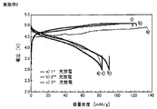
- FIG. 4 is a graph showing charge / discharge characteristics of an evaluation battery obtained in Example 2.
- FIG. 4 is a graph showing charge / discharge characteristics of an evaluation battery obtained in Example 3.
- 6 is a graph showing charge / discharge characteristics of an evaluation battery obtained in Example 4.
- 6 is a graph showing charge / discharge characteristics of an evaluation battery obtained in Example 5.
- FIG. 6 is a graph showing charge / discharge characteristics of an evaluation battery obtained in Example 6.
- FIG. 3 is an XRD measurement result of evaluation batteries (before charging and discharging) obtained in Examples 1 to 3.
- 3 is an XRD measurement result of evaluation batteries obtained in Examples 1 to 3 (after being charged and discharged twice).
- the cathode active material of the present invention is a positive electrode active material used in a Li-ion and Na-ion hybrid ion battery, and has a Na 4 M 3 (PO 4 ) 2 P 2 O 7 crystal phase (M is Ni, Co, And at least one of Mn, Fe, V, Cr, Cu, and Zn.).
- the Na 4 M 3 (PO 4 ) 2 P 2 O 7 crystal phase by containing the Na 4 M 3 (PO 4 ) 2 P 2 O 7 crystal phase, it can be used in a Li-ion and Na-ion hybrid ion battery, and can be a positive electrode active material that operates at a high potential. be able to.
- the mechanism by which Li ions and Na ions are inserted into and desorbed from the Na 4 M 3 (PO 4 ) 2 P 2 O 7 crystal phase is not necessarily clear. It is presumed that Na ions in the crystal phase are coinserted and desorbed into the ion channel in which the Na ions are arranged. Therefore, it is thought that it can be used for the above-described hybrid ion battery by containing the Na 4 M 3 (PO 4 ) 2 P 2 O 7 crystal phase.
- the positive electrode active material of the present invention has an advantage that it can operate at a higher potential than conventional positive electrode active materials that can be used in hybrid ion batteries.
- the use of the positive electrode active material of the present invention has an advantage that a hybrid ion battery having a larger potential difference (voltage) can be obtained.
- the conventional positive electrode active material that can be used in the hybrid ion battery include Na-containing compounds such as Na 2 MnPO 4 F, Na 2 FePO 4 F, and NaVPO 4 F (for example, Patent Document 1, Non-Patent Document). 1-3)). Since these Na-containing compounds operate at a lower potential than the Na 4 M 3 (PO 4 ) 2 P 2 O 7 crystal phase in the present invention, the potential difference of the hybrid ion battery described above is small, and the energy density is low. It will be lower.
- the positive electrode active material of the present invention has a Na 4 M 3 (PO 4 ) 2 P 2 O 7 crystal phase.
- the presence of the “Na 4 M 3 (PO 4 ) 2 P 2 O 7 crystal phase” in the present invention can be confirmed by, for example, X-ray diffraction (XRD) measurement.
- the presence of the crystal phase having these compositions can be confirmed by XRD measurement.
- the positive electrode active material mainly Na 4 M 3 (PO 4) 2 P 2 O 7 is preferably the proportion of the crystal phase is large, Na 4 M 3 specifically (PO 4) 2 P 2 O 7 crystalline phase It is preferable to contain as.
- “mainly composed of Na 4 M 3 (PO 4 ) 2 P 2 O 7 crystal phase” means Na 4 M 3 (PO 4 ) among all crystal phases contained in the positive electrode active material. It means that the ratio of 2 P 2 O 7 crystal phase is the largest.
- the ratio of the Na 4 M 3 (PO 4 ) 2 P 2 O 7 crystal phase contained in the positive electrode active material is preferably 50 mol% or more, more preferably 60 mol% or more, and 70 mol% or more. More preferably.
- the positive electrode active material may be composed of only a Na 4 M 3 (PO 4 ) 2 P 2 O 7 crystal phase (single-phase active material).
- the proportion of the Na 4 M 3 (PO 4 ) 2 P 2 O 7 crystal phase contained in the positive electrode active material is, for example, a quantitative analysis method by X-ray diffraction (for example, a quantitative method by R value, Rietveld method) Can be determined.
- M contained in the Na 4 M 3 (PO 4 ) 2 P 2 O 7 crystal phase is usually at least one of Ni, Co, Mn, Fe, V, Cr, Cu, and Zn, among which Ni, Co, and It is preferable that it is at least one of Mn. This is because it becomes a positive electrode active material operable at a high potential.
- the M is not particularly limited as long as it has at least one of the above-described elements, and may be only one of the above-described elements, or a combination of the above-described elements and other elements. There may be. Specifically, when M includes Co, the M may be, for example, only Co, a combination of Co and Mn, or a combination of Co, Mn, and Ni. .
- the M is a combination of a plurality of elements as described above, it if an element as a main component and M A, as the M A / M (molar ratio) in the above general formula, for example, is 0.5 or more Is preferably 0.6 or more, more preferably 0.7 or more, and particularly preferably 0.8 or more.
- a crystal phase for example, Na 4 Co 2.4 Mn 0.6 (PO 4 ) 2 P 2 O 7 crystal phase, Na 4 Co 2.4 Mn 0.3 Ni 0.3 (PO 4 ) 2 P 2 O 7 crystal phase and the like.
- the positive electrode active material of the present invention preferably has a crystal structure belonging to the space group Pn2 1 a.
- the positive electrode active material of the present invention preferably has a crystal structure belonging to the space group Pn2 1 a.
- all of the Na ions in the crystal structure are arranged in any of the a-axis, b-axis, and c-axis, which is very advantageous for Na ion conduction. It is possible.
- the shape of the positive electrode active material of the present invention is preferably, for example, a particulate shape.
- the average particle diameter (D 50 ) is preferably in the range of, for example, 1 nm to 100 ⁇ m, and more preferably in the range of 10 nm to 30 ⁇ m.
- the method for producing a positive electrode active material of the present invention is not particularly limited as long as it is a method capable of obtaining the above-described active material.
- starting materials such as a Na source, an M source, and a P source are added at a predetermined ratio.
- Each starting material is not particularly limited, and can be appropriately selected.
- Each starting material may be used alone or in combination of two or more.
- One starting material may contain two or more of Na, M, P and the like.
- the Na source is not particularly limited as long as it is a compound containing Na.
- the M source is not particularly limited as long as it is a compound containing M.
- M examples thereof include CoCO 3 , (CH 3 COO) 2 Co, CoO, and Co 2 O 3 .
- Mn for example, MnCO 3
- Mn include a (CH 3 COO) 2 Mn or the like.
- M Ni, for example, (CH 3 COO) 2 Ni, NiCO 3 , NiO and the like
- M is Fe
- Fe for example, FeO, Fe 2 O 3 , Fe (NO 3 ) 3 and the like can be mentioned.
- V for example, V 2 O 3 , V 2 O 5 , NH 4 VO 3 and the like can be mentioned.
- M when M is Cr, it includes a Cr 2 O 3, Cr (NO 3) 3 and the like.
- M when M is Cu, for example, (CH 3 COO) 2 Cu, CuO and the like can be mentioned.
- M when M is Zn, for example, a (CH 3 COO) 2 Zn, ZnO and the like.
- the P source is not particularly limited as long as it is a compound containing P.
- Na 2 P 2 O 7. Na 3 PO 4 and the like can be mentioned.
- the firing conditions are not particularly limited as long as the desired positive electrode active material can be obtained.
- the firing temperature is preferably in the range of 500 ° C. to 800 ° C., and more preferably in the range of 550 ° C. to 750 ° C. This is because if the firing temperature is too low, solid phase reaction may not occur, and if the firing temperature is too high, an unnecessary crystal phase may be generated.
- the firing time is preferably in the range of 1 hour to 100 hours, and more preferably in the range of 15 hours to 50 hours.
- the air atmosphere that is the atmosphere during firing means an oxygen-containing gas atmosphere.
- temporary firing may be performed before firing (main firing) under the above firing conditions.
- temporary baking conditions if the target positive electrode active material is obtained, it will not specifically limit.
- the calcination temperature is usually lower than the main calcination temperature and may be within the range of 150 to 500 ° C., preferably 180 to 450 ° C., more preferably 250 to 350 ° C. .
- the calcination time is not particularly limited and may be set as appropriate. For example, it may be about 1 to 5 hours.
- the air atmosphere which is the atmosphere at the time of temporary baking is the same as that at the time of the said baking.
- the following method can be exemplified. That is, a raw material mixture in which starting raw materials such as a Na source, an M source, and a P source are mixed at a predetermined ratio is prepared, and the raw material mixture is dissolved and heated in an acidic solution together with a gelling agent to prepare a gel. Next, the obtained mixture (gel) is baked in an air atmosphere (sol-gel method).
- Starting materials such as Na source, M source, and P source used in the sol-gel method may be selected as long as they can be dissolved in an acidic solution. Each starting material may be used alone or in combination of two or more. One starting material may contain two or more of Na, M, P and the like.
- examples of the Na source include Na 4 P 2 O 7 , Na 2 CO 3 , Na 2 O, Na 2 O 2 , and CH 3 COONa.
- the M source is not particularly limited as long as it is a compound containing M.
- M is Co
- examples thereof include CoCO 3 , (CH 3 COO) 2 Co, and Co 2 O 3 .
- Mn for example MnCO 3, MnO, MnO 2
- MnO include a (CH 3 COO) 2 Mn or the like.
- M is Ni, for example, (CH 3 COO) 2 Ni and the like can be mentioned.
- M is Fe for example, Fe (NO 3 ) 3 , FeC 2 O 4 , (CH 3 COO) 3 Fe and the like can be mentioned.
- M is V
- V for example, V 2 O 3 , V 2 O 5 and the like can be mentioned.
- M Cr
- Cr (NO 3 ) 3 and the like can be mentioned.
- M Cu
- (CH 3 COO) 2 Cu and the like can be mentioned.
- M Zn
- (CH 3 COO) 2 Zn and the like can be mentioned.
- Examples of the P source include NH 4 H 2 PO 4 , (NH 4 ) 2 HPO 4 , H 3 PO 4, and the like.
- the gelling agent examples include glycolic acid. Moreover, as an acidic solution, nitric acid aqueous solution etc. are mentioned, for example.
- the heating temperature at the time of gel preparation may be 60 ° C. to 120 ° C., for example, as long as the gel can be prepared by dissolving each compound in an acidic solution.
- the firing temperature of the gel can be, for example, 500 ° C. to 800 ° C., and preferably 600 ° C. to 750 ° C.
- the air atmosphere at the time of gel baking is the same as the air atmosphere in the solid phase method.
- the hybrid ion battery of the present invention includes a positive electrode active material layer containing a positive electrode active material, a negative electrode active material layer containing a negative electrode active material, and an electrolyte formed between the positive electrode active material layer and the negative electrode active material layer.
- the negative electrode active material is an active material capable of occluding and releasing Li ions, and the electrolyte layer is It contains at least Li ions.
- FIG. 1 is a schematic sectional view showing an example of the hybrid ion battery of the present invention.
- a hybrid ion battery 10 shown in FIG. 1 includes a positive electrode active material layer 1, a negative electrode active material layer 2, an electrolyte layer 3 formed between the positive electrode active material layer 1 and the negative electrode active material layer 2, and a positive electrode active material. It has a positive electrode current collector 4 that collects current from the layer 1, a negative electrode current collector 5 that collects current from the negative electrode active material layer 2, and a battery case 6 that houses these members.
- the positive electrode active material contained in the positive electrode active material layer is the positive electrode active material described above, and the negative electrode active material contained in the negative electrode active material layer is an active material capable of occluding and releasing Li ions. It is characterized by.
- the hybrid ion battery of the present invention is characterized in that the electrolyte layer contains at least Li ions.
- a high voltage hybrid ion battery can be obtained by using the positive electrode active material described in the section “A. Positive electrode active material”.
- Positive electrode active material the behavior of Li ions and Na ions during charging / discharging in the hybrid ion battery of the present invention is estimated as follows. That is, during the initial charge, Na ions are desorbed in the positive electrode active material, and Li ions present in the electrolyte layer are occluded in the negative electrode active material. In the first discharge, Li ions and Na ions present in the electrolyte layer are co-inserted in the positive electrode active material, and Li ions stored in the negative electrode active material are released.
- the inserted Li ions and Na ions co-desorb in the positive electrode active material, and at least Li ions present in the electrolyte layer are occluded in the negative electrode active material.
- both ions are considered to exhibit the same behavior as during the first discharge.
- Positive electrode active material layer is a layer containing at least a positive electrode active material, and the positive electrode active material contains a Na 4 -xLi x M 3 (PO 4 ) 2 P 2 O 7 crystal phase (0 ⁇ x ⁇ 4, M is at least one of Ni, Co, Mn, Fe, V, Cr, Cu, and Zn.
- the value of x in the Na 4-x Li x M 3 (PO 4 ) 2 P 2 O 7 crystal phase is not particularly limited as long as it is usually 0 or more, and is preferably greater than 0. It is more preferably 1 or more, and further preferably 1 or more. On the other hand, the value of x is not particularly limited as long as it is smaller than 4, but is preferably 3.9 or less.
- the positive electrode active material layer in the present invention may contain at least one of a conductive material, a binder and a solid electrolyte material, if necessary, in addition to the positive electrode active material described above.
- the conductive material include a carbon material.
- specific examples of the carbon material include acetylene black, ketjen black, carbon black, coke, carbon fiber, and graphite.
- the binder is not particularly limited as long as it is chemically and electrically stable.
- a fluorine-containing binder such as polyvinylidene fluoride (PVdF) or polytetrafluoroethylene (PTFE).
- PTFE polytetrafluoroethylene
- SBR styrene butadiene rubber
- the solid electrolyte material is not particularly limited as long as it has desired ionic conductivity, and examples thereof include oxide solid electrolyte materials and sulfide solid electrolyte materials.
- the solid electrolyte material will be described in detail in the section “3. Electrolyte layer” described later.
- the content of the positive electrode active material in the positive electrode active material layer is preferably larger from the viewpoint of capacity, for example, in the range of 60% by weight to 99% by weight, particularly in the range of 70% by weight to 95% by weight. Is preferred.
- the content of the conductive material is preferably smaller as long as the desired electronic conductivity can be ensured, and is preferably in the range of 1 wt% to 30 wt%, for example.
- the content of the solid electrolyte material is preferably smaller as long as the desired ionic conductivity can be ensured, and is preferably in the range of 1 wt% to 40 wt%, for example.
- the thickness of the positive electrode active material layer varies greatly depending on the configuration of the target hybrid ion battery, but is preferably in the range of 0.1 ⁇ m to 1000 ⁇ m, for example.
- the negative electrode active material layer in the present invention is a layer containing at least a negative electrode active material.
- the negative electrode active material is an active material capable of occluding and releasing Li ions.
- the negative electrode active material used in the present invention is not particularly limited as long as it is an active material capable of occluding and releasing Li ions.
- metal Li and metal oxide are particularly preferable.
- an aspect in which the negative electrode active material is metal Li (first embodiment)
- Li titanate Li 4 Ti 5 O 12 (LTO)
- metal Li is used as the negative electrode active material.
- a high-voltage hybrid ion battery can be obtained by using a combination of the above-described positive electrode active material and metal Li as the negative electrode active material.
- a negative electrode active material used in a general hybrid ion battery for example, metal Na can be cited.
- the oxidation-reduction potential of Li is lower than the oxidation-reduction potential of Na. Therefore, when used in combination with the positive electrode active material described above, a hybrid ion battery showing a larger potential difference, that is, a higher voltage. It can be set as a hybrid ion battery.
- a 2nd embodiment is an aspect which uses LTO which is a metal oxide as a negative electrode active material.
- LTO which is a metal oxide
- a hybrid ion battery with high safety can be obtained by using a combination of the positive electrode active material described above and LTO that is a negative electrode active material.
- the reason why the safety of the hybrid ion battery can be enhanced is that the use of LTO as the negative electrode active material makes it difficult for Na ions eluted from the positive electrode active material described above during charging to be deposited on the negative electrode active material.
- the negative electrode active material layer in the present invention may further contain at least one of a conductive material, a binder and a solid electrolyte material, if necessary, in addition to the negative electrode active material.
- a conductive material, a binder, and a solid electrolyte material used for the negative electrode active material layer are the same as those of the positive electrode active material layer.
- the negative electrode active material, the conductive material, the binder and the content of the solid electrolyte material in the negative electrode active material layer are the same as those in the positive electrode active material layer.
- the thickness of the negative electrode active material layer varies greatly depending on the configuration of the target hybrid ion battery, but is preferably in the range of 0.1 ⁇ m to 1000 ⁇ m, for example.
- the electrolyte layer in the present invention is a layer formed between the positive electrode active material layer and the negative electrode active material layer, and contains at least Li ions.
- the form of the electrolyte layer is not particularly limited, and examples thereof include a liquid electrolyte layer, a gel electrolyte layer, and a solid electrolyte layer.
- the liquid electrolyte layer is usually a layer formed using an electrolytic solution.
- the electrolyte solution may be a water-based electrolyte solution or a non-aqueous electrolyte solution, but is preferably a non-aqueous electrolyte solution.
- the electrolytic solution usually contains a Li salt and an aqueous solvent or a non-aqueous solvent.
- Li salt examples include inorganic Li salts such as LiPF 6 , LiBF 4 , LiClO 4 and LiAsF 6 ; and LiCF 3 SO 3 , LiN (CF 3 SO 2 ) 2 , LiN (C 2 F 5 SO 2 ) 2 , Examples thereof include organic Li salts such as LiN (FSO 2 ) 2 and LiC (CF 3 SO 2 ) 3 .
- the aqueous solvent is not particularly limited as long as it contains water as a main component and dissolves the Li salt. Further, the non-aqueous solvent is not particularly limited as long as it dissolves the Li salt.
- cyclic esters such as ethylene carbonate (EC), propylene carbonate (PC), butylene carbonate (BC), ⁇ -butyrolactone, sulfolane, N-methylpyrrolidone (NMP), 1, And 3-dimethyl-2-imidazolidinone (DMI).
- EC ethylene carbonate
- PC propylene carbonate
- BC butylene carbonate
- NMP N-methylpyrrolidone
- DMI 1, And 3-dimethyl-2-imidazolidinone
- chain esters such as dimethyl carbonate (DMC), diethyl carbonate (DEC), and ethyl methyl carbonate (EMC), acetates such as methyl acetate and ethyl acetate, 2-methyl
- DMC dimethyl carbonate
- DEC diethyl carbonate
- EMC ethyl methyl carbonate
- acetates such as methyl acetate and ethyl acetate
- 2-methyl Mention may be made of ethers such as tetrahydrofuran.
- a low volatile liquid such as an ionic liquid may be used as the nonaqueous electrolytic solution.
- the concentration of the Li salt in the electrolytic solution is, for example, preferably in the range of 0.3 mol / dm 3 to 5 mol / dm 3 , particularly preferably in the range of 0.8 mol / dm 3 to 1.5 mol / dm 3 . This is because if the Li salt concentration is too low, the capacity may be reduced at a high rate, and if the Li salt concentration is too high, the viscosity may be increased and the capacity may be reduced at a low temperature.
- the gel electrolyte layer can be obtained, for example, by adding a polymer to a non-aqueous electrolyte and gelling. Specifically, gelation can be performed by adding a polymer such as polyethylene oxide (PEO), polyacrylonitrile (PAN), or polymethyl methacrylate (PMMA) to the nonaqueous electrolytic solution.
- a polymer such as polyethylene oxide (PEO), polyacrylonitrile (PAN), or polymethyl methacrylate (PMMA)
- the solid electrolyte layer is a layer made of a solid electrolyte material.
- the solid electrolyte material is not particularly limited as long as it has Li ion conductivity, and examples thereof include oxide solid electrolyte materials and sulfide solid electrolyte materials.
- oxide solid electrolyte material include Li 1 + x Al x Ge 2-x (PO 4 ) 3 (0 ⁇ x ⁇ 2) and Li 1 + x Al x Ti 2-x (PO 4 ) 3 (0 ⁇ x ⁇ 2).
- examples of the sulfide solid electrolyte material include a Li 2 S—P 2 S 5 compound, a Li 2 S—SiS 2 compound, and a Li 2 S—GeS 2 compound.
- the solid electrolyte material in the present invention may be amorphous or crystalline.
- the shape of the solid electrolyte material is preferably particulate.
- the average particle diameter (D 50 ) of the solid electrolyte material is preferably in the range of 1 nm to 100 ⁇ m, for example, and more preferably in the range of 10 nm to 30 ⁇ m.
- the electrolyte layer in the present invention is not particularly limited as long as it contains at least Li ions, but may further contain Na ions.
- the electrolyte layer when it is a liquid electrolyte layer, it may further contain a Na salt.
- Na salts include inorganic Na salts such as NaPF 6 , NaBF 4 , NaClO 4 and NaAsF 6 ; and NaCF 3 SO 3 , NaN (CF 3 SO 2 ) 2 , NaN (C 2 F 5 SO 2 ) 2 , organic Na salts such as NaN (FSO 2 ) 2 , NaC (CF 3 SO 2 ) 3 and the like.
- the electrolyte layer When the electrolyte layer is a solid electrolyte layer, it may further contain a solid electrolyte material having Na ion conductivity.
- a solid electrolyte material having Na ion conductivity examples include Na 3 Zr 2 Si 2 PO 12 , ⁇ -alumina solid electrolyte (for example, Na 2 O-11Al 2 O 3 ), and the like.
- the sulfide solid electrolyte material having Na ion conductivity include Na 2 S—P 2 S 5 .
- the thickness of the electrolyte layer varies greatly depending on the type of electrolyte and the configuration of the target hybrid ion battery.
- the thickness of the electrolyte layer may be in the range of 0.1 ⁇ m to 1000 ⁇ m, and in particular in the range of 0.1 ⁇ m to 300 ⁇ m. preferable.
- the hybrid ion battery of the present invention has at least the positive electrode active material layer, the negative electrode active material layer, and the electrolyte layer described above. Furthermore, it usually has a positive electrode current collector for collecting current of the positive electrode active material layer and a negative electrode current collector for collecting current of the negative electrode active material layer.
- a positive electrode current collector for collecting current of the positive electrode active material layer
- a negative electrode current collector for collecting current of the negative electrode active material layer.
- examples of the material for the positive electrode current collector include SUS, aluminum, nickel, iron, titanium, and carbon.
- examples of the material for the negative electrode current collector include SUS, copper, nickel, and carbon.
- Examples of the shapes of the positive electrode current collector and the negative electrode current collector include a foil shape, a mesh shape, and a porous shape.
- the hybrid ion battery of the present invention may have a separator between the positive electrode active material layer and the negative electrode active material layer. This is because a battery with higher safety can be obtained.
- the material of the separator include porous films such as polyethylene (PE), polypropylene (PP), cellulose, and polyvinylidene fluoride; and nonwoven fabrics such as a resin nonwoven fabric and a glass fiber nonwoven fabric.
- the separator may have a single layer structure (for example, PE or PP), or may have a laminated structure (for example, PP / PE / PP).
- the battery case of a general battery can be used for the battery case used for this invention. Examples of the battery case include a SUS battery case.
- Hybrid ion battery The hybrid ion battery of the present invention is not particularly limited as long as it has the positive electrode active material layer, the negative electrode active material layer, and the electrolyte layer described above. Further, the hybrid ion battery of the present invention may be a primary battery or a secondary battery, but among them, a secondary battery is preferable. This is because it can be repeatedly charged and discharged and is useful, for example, as an in-vehicle battery. In addition, examples of the shape of the hybrid ion battery of the present invention include a coin type, a laminate type, a cylindrical type, and a square type. In addition, the method of manufacturing the hybrid ion battery is not particularly limited as long as it is a method capable of manufacturing the above-described hybrid ion battery.
- the present invention is not limited to the above embodiment.
- the above-described embodiment is an exemplification, and the present invention has substantially the same configuration as the technical idea described in the claims of the present invention, and any device that exhibits the same function and effect is the present invention. It is included in the technical scope of the invention.
- the obtained raw material mixture was dissolved in an aqueous nitric acid solution together with glycolic acid (gelator) and stirred at 80 ° C. The obtained mixture (gel) was baked at 700 ° C. for 50 hours in an air atmosphere. As a result, a positive electrode active material having a Na 4 Co 3 (PO 4 ) 2 P 2 O 7 crystal phase (space group Pn2 1 a) was obtained.
- An evaluation battery using the obtained positive electrode active material was produced.
- the slurry was mixed and dispersed in N-methyl 2-pyrrolidone (NMP) as a dispersant.
- NMP N-methyl 2-pyrrolidone
- a CR2032-type coin cell was used, the test electrode was used as a working electrode, metal Li was used as a counter electrode, and a microporous membrane separator of polypropylene / polyethylene / polypropylene was used as a separator.
- Example 4 A battery for evaluation was produced in the same manner as in Example 1 except that Li 4 Ti 5 O 12 (LTO) was used as the counter electrode.
- LTO Li 4 Ti 5 O 12
- Example 5 An evaluation battery was produced in the same manner as in Example 2 except that Li 4 Ti 5 O 12 (LTO) was used as the counter electrode.
- LTO Li 4 Ti 5 O 12
- Example 6 A battery for evaluation was produced in the same manner as in Example 3 except that Li 4 Ti 5 O 12 (LTO) was used as the counter electrode.
- LTO Li 4 Ti 5 O 12
- the positive electrode active materials obtained in Examples 1 to 3 were operated at a high potential. Further, as shown in FIGS. 2 to 7, it can be confirmed that the evaluation batteries obtained in Examples 1 to 3 have an average voltage of about 4.0 V to 4.5 V, which is obtained in Examples 4 to 6. It was confirmed that even in the evaluation battery thus obtained, the average voltage was about 2.5V to 3.0V. Further, in the evaluation batteries obtained in Examples 1 to 3, the discharge capacity density is about 80 mAh / g, and in the evaluation batteries obtained in Examples 4 to 6, the discharge capacity density is about 70 mAh / g. I was able to confirm.
- XRD measurement The X-ray diffraction (XRD) measurement using CuK ⁇ rays was performed on the test electrodes (working electrodes) obtained in Examples 1 to 3 before charging and discharging. The result is shown in FIG.
- X-ray diffraction (XRD) measurement was similarly performed on the test electrodes after the two-cycle charge / discharge test was performed under the conditions shown in Table 1. It was. The result is shown in FIG.
- the conditions at the time of measurement are as follows. Measurement range: 9 ° to 39 °. Scanning speed: 10 ° / min, integration count: 5 times
Landscapes
- Chemical & Material Sciences (AREA)
- Chemical Kinetics & Catalysis (AREA)
- Electrochemistry (AREA)
- General Chemical & Material Sciences (AREA)
- Engineering & Computer Science (AREA)
- Inorganic Chemistry (AREA)
- Manufacturing & Machinery (AREA)
- Materials Engineering (AREA)
- Crystallography & Structural Chemistry (AREA)
- Battery Electrode And Active Subsutance (AREA)
- Secondary Cells (AREA)
Abstract
本発明は、LiイオンおよびNaイオンのハイブリッドイオン電池に使用され、高電位で作動する正極活物質を提供することを主目的とする。 本発明は、LiイオンおよびNaイオンのハイブリッドイオン電池に用いられる正極活物質であって、Na4M3(PO4)2P2O7結晶相(Mは、Ni、Co、Mn、Fe、V、Cr、CuおよびZnの少なくとも一種である。)を含有することを特徴とする正極活物質を提供することにより、上記課題を解決する。
Description
本発明は、LiイオンおよびNaイオンのハイブリッドイオン電池に使用され、高電位で作動する正極活物質に関する。
近年におけるパソコン、ビデオカメラおよび携帯電話等の情報関連機器や通信機器等の急速な普及に伴い、その電源として優れた電池の開発が重要視されている。また、情報関連機器や通信関連機器以外の分野では、例えば自動車産業界において、電気自動車やハイブリッド自動車に用いられる電池としてリチウムイオン電池やナトリウムイオン電池等の開発が進められている。NaはLiに比べて豊富に存在することから、ナトリウムイオン電池は、リチウムイオン電池に比べて低コスト化を図りやすいという利点がある。
また2つのイオン(例えばLiイオンおよびNaイオン)が電池内を移動するハイブリッドイオン電池が研究されている。このようなハイブリッドイオン電池は、通常、正極活物質を含有する正極活物質層と、負極活物質を含有する負極活物質層と、正極活物質層および負極活物質層の間に形成された電解質層とを有する。例えば、特許文献1では、ハイブリッドイオン電池の正極活物質として使用可能なNa2MPO4F(Mは、FeもしくはMnかその化合物)が開示されている。また非特許文献1~3においても、ハイブリッド電池の正極活物質として使用可能な種々のNa含有化合物が開示されている。具体的には、Na2FePO4F、NaVPO4FおよびNa3V2(PO4)2F3が記載されている。
B.L.Ellis et al., "A multifunctional 3.5V iron-based phosphate cathode for rechargeable batteries", Nature Materials Vol.6 October 2007
Jianqing Zhao et al., "A novel sol-gel synthesis route to NaVPO4F as cathode material for hybrid lithium ion batteries", Journal of Power Sources, 195 (2010) 6854-6859
J.Barker et al.,"Li4/3Ti5/3O4 // Na3V2(PO4)2F3: An Example of a Hybrid-Ion Cell Using a Non-graphitic Anode", Journal of Electrochemical Society, 154 (9) A882-A887 (2007)
電池の高電圧化を図る目的から、一般的に正極活物質は高電位で作動することが好ましい。そのため、上記実情に鑑み、本発明は、LiイオンおよびNaイオンのハイブリッドイオン電池に使用され、高電位で作動する正極活物質を提供することを主目的とする。
上記課題を解決するために、本発明においては、LiイオンおよびNaイオンのハイブリッドイオン電池に用いられる正極活物質であって、Na4M3(PO4)2P2O7結晶相(Mは、Ni、Co、Mn、Fe、V、Cr、CuおよびZnの少なくとも一種である。)を含有することを特徴とする正極活物質を提供する。
本発明によれば、Na4M3(PO4)2P2O7結晶相を含有することで、LiイオンおよびNaイオンのハイブリッドイオン電池で使用でき、高電位で作動する正極活物質とすることができる。
また本発明においては、正極活物質を含有する正極活物質層と、負極活物質を含有する負極活物質層と、上記正極活物質層および上記負極活物質層の間に形成される電解質層とを有するハイブリッドイオン電池であって、上記正極活物質が、Na4-xLixM3(PO4)2P2O7結晶相(0≦x<4、Mは、Ni、Co、Mn、Fe、V、Cr、CuおよびZnの少なくとも一種である。)を含有する正極活物質であり、上記負極活物質が、Liイオンを吸蔵放出可能な活物質であり、上記電解質層が、少なくともLiイオンを含有することを特徴とするハイブリッドイオン電池を提供する。
本発明によれば、上述した正極活物質を用いることで、従来のハイブリッドイオン電池(例えば特許文献1)に比べて、高電圧のハイブリッドイオン電池とすることができる。
上記発明においては、上記負極活物質が、Li金属であることが好ましい。より高電圧のハイブリッドイオン電池とすることができるからである。
上記発明においては、上記負極活物質が、チタン酸リチウムであることが好ましい。安全性に優れたハイブリッドイオン電池とすることができるからである。
本発明の正極活物質は、LiイオンおよびNaイオンのハイブリッドイオン電池に使用でき、高電位で作動するという効果を奏する。
以下、本発明の正極活物質およびハイブリッドイオン電池について詳細に説明する。
A.正極活物質
まず、本発明の正極活物質について説明する。本発明の正極活物質は、LiイオンおよびNaイオンのハイブリッドイオン電池に用いられる正極活物質であって、Na4M3(PO4)2P2O7結晶相(Mは、Ni、Co、Mn、Fe、V、Cr、CuおよびZnの少なくとも一種である。)を含有することを特徴とするものである。
まず、本発明の正極活物質について説明する。本発明の正極活物質は、LiイオンおよびNaイオンのハイブリッドイオン電池に用いられる正極活物質であって、Na4M3(PO4)2P2O7結晶相(Mは、Ni、Co、Mn、Fe、V、Cr、CuおよびZnの少なくとも一種である。)を含有することを特徴とするものである。
本発明によれば、Na4M3(PO4)2P2O7結晶相を含有することで、LiイオンおよびNaイオンのハイブリッドイオン電池で使用でき、高電位で作動する正極活物質とすることができる。ここで、上記ハイブリッドイオン電池において、LiイオンおよびNaイオンが上記Na4M3(PO4)2P2O7結晶相に挿入脱離されるメカニズムについては、必ずしも明らかではないが、上記両イオンが上記結晶相内のNaイオンが配列しているイオンチャンネル内に共挿入、共脱離されると推測される。そのため、上記Na4M3(PO4)2P2O7結晶相を含有することで、上述したハイブリッドイオン電池に使用できると考えられる。
また、本発明の正極活物質は、ハイブリッドイオン電池に使用できる従来の正極活物質に比べて、高い電位で作動できるという利点がある。その結果、本発明の正極活物質を使用することで、より電位差(電圧)の大きいハイブリッドイオン電池とすることができるという利点を有する。ここで、ハイブリッドイオン電池に使用できる従来の正極活物質としては、例えばNa2MnPO4F、Na2FePO4F、NaVPO4F等のNa含有化合物が挙げられる(例えば特許文献1、非特許文献1~3等)。これらのNa含有化合物は、本発明におけるNa4M3(PO4)2P2O7結晶相に比べて低い電位で作動するため、上述したハイブリッドイオン電池の電位差は小さくなり、またエネルギー密度が低くなってしまう。
本発明の正極活物質は、Na4M3(PO4)2P2O7結晶相を有する。本発明における「Na4M3(PO4)2P2O7結晶相」の存在は、例えばX線回折(XRD)測定により確認することができる。これらの組成の結晶相の存在について、XRD測定により確認することができる。例えば、Na4M3(PO4)2P2O7結晶相の存在は、通常、2θ=9.8°、16°、17°、23.9°、29.5°、32.2°、34°、37°等に特徴的なピークを有することで確認することができる。なお、このピークの位置は、±1°の範囲内で前後しても良い。
上記正極活物質は、Na4M3(PO4)2P2O7結晶相の割合が多いことが好ましく、具体的にはNa4M3(PO4)2P2O7結晶相を主体として含有することが好ましい。ここで、「Na4M3(PO4)2P2O7結晶相を主体とする」とは、上記正極活物質に含まれる全ての結晶相の中で、Na4M3(PO4)2P2O7結晶相の割合が最も大きいことをいう。上記正極活物質に含まれるNa4M3(PO4)2P2O7結晶相の割合は、50mol%以上であることが好ましく、60mol%以上であることがより好ましく、70mol%以上であることがさらに好ましい。また、上記正極活物質は、Na4M3(PO4)2P2O7結晶相のみから構成されるもの(単相の活物質)であっても良い。なお、上記正極活物質に含まれるNa4M3(PO4)2P2O7結晶相の割合は、例えば、X線回折による定量分析法(例えば、R値による定量法、リートベルト法)により決定することができる。
上記Na4M3(PO4)2P2O7結晶相に含まれるMは、通常、Ni、Co、Mn、Fe、V、Cr、CuおよびZnの少なくとも一種であり、中でもNi、CoおよびMnの少なくとも一種であることが好ましい。高電位で作動可能な正極活物質となるからである。また上記Mは、上述した元素の少なくとも一種を有していれば特に限定されるものではなく、上述した元素の一種のみであっても良く、上述した元素と他の元素とを組み合わせたものであっても良い。具体的には、上記MがCoを有する場合、上記Mとしては、例えばCoのみであっても良く、CoおよびMnの組み合わせであっても良く、Co、MnおよびNiの組み合わせであっても良い。
上記Mが上述した複数の元素を組み合わせたものである場合、主成分となる元素をMAとすると、上記一般式におけるMA/M(モル比)としては、例えば0.5以上であることが好ましく、0.6以上であることがより好ましく、0.7以上であることがさらに好ましく、0.8以上であることが特に好ましい。このような結晶相としては、例えば、Na4Co2.4Mn0.6(PO4)2P2O7結晶相、Na4Co2.4Mn0.3Ni0.3(PO4)2P2O7結晶相等を挙げることができる。
また本発明の正極活物質は、空間群Pn21aに帰属する結晶構造を有することが好ましい。上記空間群に帰属する結晶構造を有する場合、結晶構造内のNaイオンの全てが、a軸、b軸およびc軸のいずれかの方向に配列し、Naイオンの伝導に非常に有利であると考えられるからである。
本発明の正極活物質の形状は、例えば粒子状であることが好ましい。また、その平均粒径(D50)は、例えば1nm~100μmの範囲内、中でも10nm~30μmの範囲内であることが好ましい。
本発明の正極活物質の製造方法は、上述した活物質を得ることができる方法であれば特に限定されるものではなく、例えばNa源、M源およびP源等の出発原料を所定の割合で混合した原料混合物を準備し、その原料混合物を大気雰囲気下で焼成する方法(固相法)を挙げることができる。各出発原料は特に限定されず、適宜選択することができる。各出発原料は、1種を単独で用いても良く、2種以上を組み合わせて用いても良い。また、1つの出発原料が、Na、MおよびP等のうちの2種以上を含むものであっても良い。
上記Na源としてはNaを含有する化合物であれば特に限定されるものではなく、例えばNa4P2O7、Na2CO3、Na2O、Na2O2、Na3PO4、およびCH3COONa等を挙げることができる。
上記M源としては、Mを含有する化合物であれば特に限定されるものではない。MがCoである場合、例えば、CoCO3、(CH3COO)2Co、CoO、Co2O3等を挙げられる。またMがMnである場合、例えば、MnCO3、(CH3COO)2Mn等を挙げられる。MがNiである場合、例えば、(CH3COO)2Ni、NiCO3、NiO等を挙げられる。またMがFeである場合、例えば、FeO、Fe2O3、Fe(NO3)3等を挙げられる。MがVである場合、例えば、V2O3、V2O5、NH4VO3等を挙げられる。またMがCrである場合、Cr2O3、Cr(NO3)3等を挙げられる。MがCuである場合、例えば、(CH3COO)2Cu、CuO等を挙げられる。またMがZnである場合、例えば、(CH3COO)2Zn、ZnO等を挙げられる。
上記P源としてはPを含有する化合物であれば特に限定されるものではなく、例えば、Na4P2O7、NH4H2PO4、(NH4)2HPO4、H3PO4.Na2P2O7.Na3PO4等を挙げることができる。
焼成条件としては、目的とする正極活物質を得られるものであれば特に限定されるものではない。具体的には、焼成温度が、例えば500℃~800℃の範囲内、中でも550℃~750℃の範囲内であることが好ましい。焼成温度が低すぎると、固相反応が生じない可能性があり、焼成温度が高すぎると、不要な結晶相が生成する可能性があるからである。また、焼成時間は、例えば1時間~100時間の範囲内、中でも15時間~50時間の範囲内であることが好ましい。焼成時の雰囲気である大気雰囲気とは、酸素含有ガス雰囲気を意味する。
また、本発明の正極活物質の製造方法としては、上記焼成条件で焼成(本焼成)を行う前に、仮焼成を行っても良い。なお、仮焼成条件としては、目的とする正極活物質を得られるものであれば特に限定されない。具体的には、仮焼成の温度は、通常、本焼成の温度よりも低く、150~500℃の範囲内であればよいが、好ましくは180~450℃、より好ましくは250~350℃である。仮焼成時間は、特に限定されず、適宜設定すればよいが、例えば、1~5時間程度とすることができる。また、仮焼成時の雰囲気である大気雰囲気は、上記焼成時と同様である。
また、本発明の正極活物質の他の製造方法としては、次のような方法を挙げることができる。すなわち、Na源、M源およびP源等の出発原料を所定の割合で混合した原料混合物を準備し、その原料混合物を、ゲル化剤とともに酸性溶液中に溶解、加熱し、ゲルを調製する。次に、得られた混合物(ゲル)を、大気雰囲気下で焼成する方法(ゾルゲル法)である。
ゾルゲル法で使用されるNa源、M源およびP源等の出発原料としては、酸性溶液に溶解可能なものであればよく、適宜選択することができる。各出発原料は、1種を単独で用いても良く、2種以上を組み合わせて用いても良い。また、1つの出発原料が、Na、MおよびP等のうちの2種以上を含むものであってもよい。
具体的には、Na源として、例えば、Na4P2O7、Na2CO3、Na2O、Na2O2、及びCH3COONa等が挙げられる。
またM源としては、Mを含有する化合物であれば特に限定されるものではなく、MがCoである場合、例えばCoCO3、(CH3COO)2Co、Co2O3等を挙げられる。またMがMnである場合、例えばMnCO3、MnO、MnO2、(CH3COO)2Mn等を挙げられる。MがNiである場合、例えば、(CH3COO)2Ni等を挙げられる。またMがFeである場合、例えば、Fe(NO3)3、FeC2O4、(CH3COO)3Fe等を挙げられる。MがVである場合、例えば、V2O3、V2O5等を挙げられる。またMがCrである場合、例えば、Cr(NO3)3等を挙げられる。MがCuである場合、例えば、(CH3COO)2Cu等を挙げられる。またMがZnである場合、例えば、(CH3COO)2Zn等を挙げられる。
P源として、例えば、NH4H2PO4、(NH4)2HPO4、H3PO4等が挙げられる。
ゲル化剤としては、例えば、グリコール酸等が挙げられる。また、酸性溶液としては、例えば、硝酸水溶液等が挙げられる。ゲル調製時の上記加熱温度は、上記各化合物を酸性溶液に溶解させ、ゲルを調製することができればよく、例えば、60℃~120℃とすることができる。ゲルの焼成温度は、例えば、500℃~800℃とすることができ、好ましくは600℃~750℃である。ゲル焼成時の大気雰囲気とは、固相法における大気雰囲気と同様である。
B.ハイブリッドイオン電池
次に、本発明のハイブリッドイオン電池について説明する。本発明のハイブリッドイオン電池は、正極活物質を含有する正極活物質層と、負極活物質を含有する負極活物質層と、上記正極活物質層および上記負極活物質層の間に形成される電解質層とを有するハイブリッドイオン電池であって、上記正極活物質が、Na4-xLixM3(PO4)2P2O7結晶相(0≦x<4、Mは、Ni、Co、Mn、Fe、V、Cr、CuおよびZnの少なくとも一種である。)を含有する正極活物質であり、上記負極活物質が、Liイオンを吸蔵放出可能な活物質であり、上記電解質層が、少なくともLiイオンを含有することを特徴とするものである。
次に、本発明のハイブリッドイオン電池について説明する。本発明のハイブリッドイオン電池は、正極活物質を含有する正極活物質層と、負極活物質を含有する負極活物質層と、上記正極活物質層および上記負極活物質層の間に形成される電解質層とを有するハイブリッドイオン電池であって、上記正極活物質が、Na4-xLixM3(PO4)2P2O7結晶相(0≦x<4、Mは、Ni、Co、Mn、Fe、V、Cr、CuおよびZnの少なくとも一種である。)を含有する正極活物質であり、上記負極活物質が、Liイオンを吸蔵放出可能な活物質であり、上記電解質層が、少なくともLiイオンを含有することを特徴とするものである。
図1は、本発明のハイブリッドイオン電池の一例を示す概略断面図である。図1に示されるハイブリッドイオン電池10は、正極活物質層1と、負極活物質層2と、正極活物質層1および負極活物質層2の間に形成される電解質層3と、正極活物質層1の集電を行う正極集電体4と、負極活物質層2の集電を行う負極集電体5と、これらの部材を収納する電池ケース6とを有するものである。本発明のハイブリッドイオン電池は、正極活物質層に含まれる正極活物質が上述した正極活物質であり、負極活物質層に含まれる負極活物質がLiイオンを吸蔵放出可能な活物質であることを特徴としている。また本発明のハイブリッドイオン電池は、電解質層が少なくともLiイオンを含有することを特徴としている。
本発明によれば、上記「A.正極活物質」の項で記載した正極活物質を用いることで、高電圧のハイブリッドイオン電池とすることができる。ここで、本発明のハイブリッドイオン電池における充放電時のLiイオンおよびNaイオンの挙動については、次のように推測される。すなわち、初回充電時において、正極活物質ではNaイオンが脱離し、負極活物質では電解質層内に存在するLiイオンが吸蔵される。また初回放電時において、正極活物質では電解質層内に存在するLiイオンおよびNaイオンが共挿入され、負極活物質では吸蔵されているLiイオンが放出される。さらに、2回目以降の充電時において、正極活物質では挿入されたLiイオンおよびNaイオンが共脱離し、負極活物質では電解質層内に存在する、少なくともLiイオンが吸蔵されると考えられる。また2回目以降の放電時については、両イオンが初回放電時と同様の挙動を示すと考えられる。
以下、本発明のハイブリッドイオン電池について、構成ごとに説明する。
以下、本発明のハイブリッドイオン電池について、構成ごとに説明する。
1.正極活物質層
本発明における正極活物質層は少なくとも正極活物質を含有する層であり、上記正極活物質は、Na4-xLixM3(PO4)2P2O7結晶相(0≦x<4、Mは、Ni、Co、Mn、Fe、V、Cr、CuおよびZnの少なくとも一種である。)を含有するものである。
本発明における正極活物質層は少なくとも正極活物質を含有する層であり、上記正極活物質は、Na4-xLixM3(PO4)2P2O7結晶相(0≦x<4、Mは、Ni、Co、Mn、Fe、V、Cr、CuおよびZnの少なくとも一種である。)を含有するものである。
上記Na4-xLixM3(PO4)2P2O7結晶相は、上述したようにハイブリッドイオン電池の充放電に伴い、LiイオンおよびNaイオンが共挿入、共脱離されると考えられる。そのため、上記一般式中のxが0≦x<4を満たす任意の組成を有する結晶相であると考えられる。すなわち、初回充電前はx=0となり、初回充電後の満充電時には0<x<4となると考えられる。このようなNa4-xLixM3(PO4)2P2O7結晶相(0<x<4)としては、例えば、2θ=16°、17°、32.2°、34°等にピークを有することが好ましい。これらのピークのうち、Na4M3(PO4)2P2O7結晶相に由来するピークとしては、例えば2θ=16°、32.2°等に現れるピークを挙げることができる。またNa4M3(PO4)2P2O7結晶相にLiイオンが挿入された際に確認できる特徴的なピークとしては、例えば、2θ=17°、34°等に現れるピークを挙げることができる。また一方、Na4M3(PO4)2P2O7結晶相にLiイオンが挿入されることで消えるピークとしては、例えば、2θ=9.8°、23.9°、37°等に位置するピークを挙げることができる。
上記Na4-xLixM3(PO4)2P2O7結晶相におけるxの値は、通常、0以上であれば特に限定されるものではなく、0より大きいことが好ましく、0.1以上であることがより好ましく、1以上であることがさらに好ましい。一方、上記xの値は、通常、4より小さければ特に限定されるものではないが、3.9以下であることが好ましい。
また上記Na4-xLixM3(PO4)2P2O7結晶相におけるMは、上記「A.正極活物質」の項に記載した内容と同様であるため、ここでの記載は省略する。
本発明における正極活物質層は、上述した正極活物質の他に、必要に応じて、導電化材、結着材および固体電解質材料の少なくとも一つを含有しても良い。導電化材としては、例えば炭素材料を挙げることができる。さらに、炭素材料としては、具体的には、アセチレンブラック、ケッチェンブラック、カーボンブラック、コークス、炭素繊維、黒鉛等を挙げることができる。また結着剤としては、化学的、電気的に安定なものであれば特に限定されるものではないが、例えば、ポリフッ化ビニリデン(PVdF)、ポリテトラフルオロエチレン(PTFE)等のフッ素含有結着材、スチレンブタジエンゴム(SBR)等のゴム系結着材等を挙げることができる。また、固体電解質材料としては、所望のイオン伝導性を有するものであれば特に限定されるものではないが、例えば酸化物固体電解質材料、硫化物固体電解質材料を挙げることができる。なお、固体電解質材料については、後述する「3.電解質層」の項で詳細に説明する。
正極活物質層における正極活物質の含有量は、容量の観点からはより多いことが好ましく、例えば60重量%~99重量%の範囲内、中でも70重量%~95重量%の範囲内であることが好ましい。また、導電化材の含有量は、所望の電子伝導性を確保できれば、より少ないことが好ましく、例えば1重量%~30重量%の範囲内であることが好ましい。また、固体電解質材料の含有量は、所望のイオン伝導性を確保できれば、より少ないことが好ましく、例えば1重量%~40重量%の範囲内であることが好ましい。
正極活物質層の厚さは、目的とするハイブリッドイオン電池の構成によって大きく異なるものであるが、例えば、0.1μm~1000μmの範囲内であることが好ましい。
2.負極活物質層
本発明における負極活物質層は、少なくとも負極活物質を含有する層である。また、上記負極活物質がLiイオンを吸蔵放出可能な活物質であることを特徴とする。本発明に用いられる負極活物質としては、Liイオンを吸蔵放出可能な活物質であれば特に限定されるものではなく、例えば、金属Li、Li合金、金属酸化物、金属硫化物、金属窒化物、およびグラファイト等の炭素材料等を挙げることができる。本発明においては、中でも、金属Li、金属酸化物であることが好ましい。ここで、負極活物質が金属Liである態様(第1実施態様)、また金属酸化物の一例であるチタン酸リチウム(Li4Ti5O12(LTO))である態様(第2実施態様)についてそれぞれ説明する。
本発明における負極活物質層は、少なくとも負極活物質を含有する層である。また、上記負極活物質がLiイオンを吸蔵放出可能な活物質であることを特徴とする。本発明に用いられる負極活物質としては、Liイオンを吸蔵放出可能な活物質であれば特に限定されるものではなく、例えば、金属Li、Li合金、金属酸化物、金属硫化物、金属窒化物、およびグラファイト等の炭素材料等を挙げることができる。本発明においては、中でも、金属Li、金属酸化物であることが好ましい。ここで、負極活物質が金属Liである態様(第1実施態様)、また金属酸化物の一例であるチタン酸リチウム(Li4Ti5O12(LTO))である態様(第2実施態様)についてそれぞれ説明する。
まず、第1実施態様について説明する。第1実施態様は、負極活物質として金属Liを使用する態様である。本実施態様によれば、上述した正極活物質と、負極活物質である金属Liとを組み合わせて用いることで、高電圧なハイブリッドイオン電池とすることができる。一般的なハイブリッドイオン電池に用いられる負極活物質としては、例えば金属Naが挙げられる。Li基準では、Liの酸化還元電位の方が、Naの酸化還元電位より低いことから、上述した正極活物質と組み合わせて用いることで、より大きな電位差を示すハイブリッドイオン電池、すなわち、より高電圧のハイブリッドイオン電池とすることができる。
次に、第2実施態様について説明する。第2実施態様は、負極活物質として金属酸化物であるLTOを使用する態様である。本実施態様によれば、上述した正極活物質と、負極活物質であるLTOとを組み合わせて用いることで、安全性の高いハイブリッドイオン電池とすることができる。ハイブリッドイオン電池の安全性を高められる理由としては、負極活物質としてLTOを用いることで、充電時に上述した正極活物質より溶出したNaイオンが負極活物質上で析出しにくくなるためと考えられる。
本発明における負極活物質層は、上記負極活物質以外に、必要に応じて、導電化材、結着材および固体電解質材料の少なくとも一つをさらに含有していても良い。なお、負極活物質層に用いられる導電化材、結着材および固体電解質材料は、上記正極活物質層と同様である。また、負極活物質層における負極活物質、導電化材、結着材および固体電解質材料の含有量についても上記正極活物質層と同様である。
負極活物質層の厚さは、目的とするハイブリッドイオン電池の構成によって大きく異なるものであるが、例えば、0.1μm~1000μmの範囲内であることが好ましい。
3.電解質層
次に、本発明における電解質層について説明する。本発明における電解質層は、上記正極活物質層および上記負極活物質層の間に形成される層であり、少なくともLiイオンを含有するものである。電解質層の形態は、特に限定されるものではなく、例えば液体電解質層、ゲル電解質層、固体電解質層等を挙げることができる。
次に、本発明における電解質層について説明する。本発明における電解質層は、上記正極活物質層および上記負極活物質層の間に形成される層であり、少なくともLiイオンを含有するものである。電解質層の形態は、特に限定されるものではなく、例えば液体電解質層、ゲル電解質層、固体電解質層等を挙げることができる。
液体電解質層は、通常、電解液を用いてなる層である。本発明においては、上記電解液が水系電解液であっても良く、非水電解液であっても良いが、中でも非水電解液であることが好ましい。また上述したように、本発明における電解質層は、少なくともLiイオンを含有するものであることから、上記電解液は、通常、Li塩と、水系溶媒または非水溶媒とを含有する。Li塩としては、例えば、LiPF6、LiBF4、LiClO4およびLiAsF6等の無機Li塩;およびLiCF3SO3、LiN(CF3SO2)2、LiN(C2F5SO2)2、LiN(FSO2)2、LiC(CF3SO2)3等の有機Li塩等を挙げることができる。また水系溶媒としては、水を主成分とし、Li塩を溶解するものであれば特に限定されるものではない。さらに非水溶媒としては、Li塩を溶解するものであれば特に限定されるものではない。例えば高誘電率溶媒としては、エチレンカーボネート(EC)、プロピレンカーボネート(PC)、ブチレンカーボネート(BC)等の環状エステル(環状カーボネート)、γ-ブチロラクトン、スルホラン、N-メチルピロリドン(NMP)、1,3-ジメチル-2-イミダゾリジノン(DMI)等を挙げることができる。一方、低粘度溶媒としては、ジメチルカーボネート(DMC)、ジエチルカーボネート(DEC)、エチルメチルカーボネート(EMC)等の鎖状エステル(鎖状カーボネート)、メチルアセテート、エチルアセテート等のアセテート類、2-メチルテトラヒドロフラン等のエーテル等を挙げることができる。高誘電率溶媒および低粘度溶媒を混合した混合溶媒を用いても良い。なお、本発明においては、非水電解液として、例えば、イオン性液体等の低揮発液体を用いても良い。
電解液におけるLi塩の濃度は、例えば、0.3mol/dm3~5mol/dm3の範囲内、中でも0.8mol/dm3~1.5mol/dm3の範囲内であることが好ましい。Li塩の濃度が低すぎるとハイレート時の容量低下が生じる可能性があり、Li塩の濃度が高すぎると粘性が高くなり低温での容量低下が生じる可能性があるからである。
ゲル電解質層は、例えば非水電解液にポリマーを添加してゲル化することで得られる。具体的には、非水電解液に、ポリエチレンオキシド(PEO)、ポリアクリロニトリル(PAN)またはポリメチルメタクリレート(PMMA)等のポリマーを添加することにより、ゲル化を行うことができる。
固体電解質層は、固体電解質材料を用いてなる層である。固体電解質材料としては、Liイオン伝導性を有するものであれば特に限定されるものではないが、例えば酸化物固体電解質材料および硫化物固体電解質材料を挙げることができる。酸化物固体電解質材料としては、例えば、Li1+xAlxGe2-x(PO4)3(0≦x≦2)、Li1+xAlxTi2-x(PO4)3(0≦x≦2)、LiLaTiO(例えば、Li0.34La0.51TiO3)、LiPON(例えば、Li2.9PO3.3N0.46)、LiLaZrO(例えば、Li7La3Zr2O12)等を挙げることができる。一方、硫化物固体電解質材料としては、例えば、Li2S-P2S5化合物、Li2S-SiS2化合物、Li2S-GeS2化合物等を挙げることができる。
本発明における固体電解質材料は、非晶質であっても良く、結晶質であっても良い。また、固体電解質材料の形状は、粒子状であることが好ましい。また、固体電解質材料の平均粒径(D50)は、例えば1nm~100μmの範囲内、中でも10nm~30μmの範囲内であることが好ましい。
本発明における電解質層は、少なくともLiイオンを含有していれば特に限定されるものではないが、さらにNaイオンを含有していても良い。例えば、電解質層が液体電解質層である場合、Na塩をさらに含有していても良い。ここで、Na塩としては、例えばNaPF6、NaBF4、NaClO4およびNaAsF6等の無機Na塩;およびNaCF3SO3、NaN(CF3SO2)2、NaN(C2F5SO2)2、NaN(FSO2)2、NaC(CF3SO2)3等の有機Na塩等を挙げることができる。また電解質層が固体電解質層である場合、Naイオン伝導性を有する固体電解質材料をさらに含有していても良い。ここで、Naイオン伝導性を有する酸化物固体電解質材料としては、例えばNa3Zr2Si2PO12、βアルミナ固体電解質(例えばNa2O-11Al2O3)等を挙げることができる。またNaイオン伝導性を有する硫化物固体電解質材料としては、例えばNa2S-P2S5等を挙げることができる。
電解質層の厚さは、電解質の種類および目的とするハイブリッドイオン電池の構成によって大きく異なるものであるが、例えば0.1μm~1000μmの範囲内、中でも0.1μm~300μmの範囲内であることが好ましい。
4.その他の構成
本発明のハイブリッドイオン電池は、上述した正極活物質層、負極活物質層および電解質層を少なくとも有するものである。さらに通常は、正極活物質層の集電を行う正極集電体、および負極活物質層の集電を行う負極集電体を有する。正極集電体の材料としては、例えばSUS、アルミニウム、ニッケル、鉄、チタンおよびカーボン等を挙げることができる。一方、負極集電体の材料としては、例えばSUS、銅、ニッケルおよびカーボン等を挙げることができる。また、正極集電体および負極集電体の形状としては、例えば、箔状、メッシュ状、多孔質状等を挙げることができる。
本発明のハイブリッドイオン電池は、上述した正極活物質層、負極活物質層および電解質層を少なくとも有するものである。さらに通常は、正極活物質層の集電を行う正極集電体、および負極活物質層の集電を行う負極集電体を有する。正極集電体の材料としては、例えばSUS、アルミニウム、ニッケル、鉄、チタンおよびカーボン等を挙げることができる。一方、負極集電体の材料としては、例えばSUS、銅、ニッケルおよびカーボン等を挙げることができる。また、正極集電体および負極集電体の形状としては、例えば、箔状、メッシュ状、多孔質状等を挙げることができる。
本発明のハイブリッドイオン電池は、正極活物質層および負極活物質層の間に、セパレータを有していても良い。より安全性の高い電池を得ることができるからである。セパレータの材料としては、例えばポリエチレン(PE)、ポリプロピレン(PP)、セルロース、ポリフッ化ビニリデン等の多孔膜;および樹脂不織布、ガラス繊維不織布等の不織布等を挙げることができる。また、セパレータは、単層構造(例えばPE、PP)であっても良く、積層構造(例えばPP/PE/PP)であっても良い。また、本発明に用いられる電池ケースには、一般的な電池の電池ケースを用いることができる。電池ケースとしては、例えばSUS製電池ケース等を挙げることができる。
5.ハイブリッドイオン電池
本発明のハイブリッドイオン電池は、上述した正極活物質層、負極活物質層および電解質層を有するものであれば特に限定されるものではない。また、本発明のハイブリッドイオン電池は、一次電池であっても良く、二次電池であっても良いが、中でも二次電池であることが好ましい。繰り返し充放電でき、例えば車載用電池として有用だからである。また、本発明のハイブリッドイオン電池の形状としては、例えばコイン型、ラミネート型、円筒型および角型等を挙げることができる。また、ハイブリッドイオン電池の製造方法としては、上述したハイブリッドイオン電池を製造できる方法であれば特に限定されるものではない。
本発明のハイブリッドイオン電池は、上述した正極活物質層、負極活物質層および電解質層を有するものであれば特に限定されるものではない。また、本発明のハイブリッドイオン電池は、一次電池であっても良く、二次電池であっても良いが、中でも二次電池であることが好ましい。繰り返し充放電でき、例えば車載用電池として有用だからである。また、本発明のハイブリッドイオン電池の形状としては、例えばコイン型、ラミネート型、円筒型および角型等を挙げることができる。また、ハイブリッドイオン電池の製造方法としては、上述したハイブリッドイオン電池を製造できる方法であれば特に限定されるものではない。
なお、本発明は、上記実施形態に限定されるものではない。上記実施形態は、例示であり、本発明の特許請求の範囲に記載された技術的思想と実質的に同一な構成を有し、同様な作用効果を奏するものは、いかなるものであっても本発明の技術的範囲に包含される。
以下に実施例を示して本発明をさらに具体的に説明する。
[実施例1]
(活物質の合成)
Na源としてNa4P2O7、Co源として(CH3COO)2Co、P源としてNH4H2PO4およびNa4P2O7を準備して混合し原料混合物を得た。なお、原料混合物中におけるNa、CoおよびPの割合が、Na:Co:P=4:3:4(モル比)となるように混合した。得られた原料混合物をグリコール酸(ゲル化剤)とともに硝酸水溶液中に溶解し、80℃で撹拌した。得られた混合物(ゲル)を大気雰囲気下、700℃で50時間焼成した。これにより、Na4Co3(PO4)2P2O7結晶相(空間群Pn21a)を有する正極活物質を得た。
(活物質の合成)
Na源としてNa4P2O7、Co源として(CH3COO)2Co、P源としてNH4H2PO4およびNa4P2O7を準備して混合し原料混合物を得た。なお、原料混合物中におけるNa、CoおよびPの割合が、Na:Co:P=4:3:4(モル比)となるように混合した。得られた原料混合物をグリコール酸(ゲル化剤)とともに硝酸水溶液中に溶解し、80℃で撹拌した。得られた混合物(ゲル)を大気雰囲気下、700℃で50時間焼成した。これにより、Na4Co3(PO4)2P2O7結晶相(空間群Pn21a)を有する正極活物質を得た。
(評価用電池の作製)
得られた正極活物質を用いた評価用電池を作製した。先ず、得られた正極活物質と、導電化材(炭素材料)と、結着材(PVdF)とを、正極活物質:導電化材:結着材=75:20:5(重量比)で混合し、分散剤であるN-メチル2-ピロリドン(NMP)中に分散させてスラリーを調製した。次に、得られたスラリーを集電体であるアルミニウム箔上に塗布して乾燥、圧延し、試験電極を作製した。
得られた正極活物質を用いた評価用電池を作製した。先ず、得られた正極活物質と、導電化材(炭素材料)と、結着材(PVdF)とを、正極活物質:導電化材:結着材=75:20:5(重量比)で混合し、分散剤であるN-メチル2-ピロリドン(NMP)中に分散させてスラリーを調製した。次に、得られたスラリーを集電体であるアルミニウム箔上に塗布して乾燥、圧延し、試験電極を作製した。
その後、CR2032型コインセルを用い、作用極として上記試験電極を用い、対極として金属Liを用い、セパレータとしてポリプロピレン/ポリエチレン/ポリプロピレンの微多孔膜セパレータを用いた。電解液には、エチレンカーボネート(EC)、ジメチルカーボネート(DMC)およびエチルメチルカーボネート(EMC)をEC:DMC:EMC=3:4:3(体積比)で混合した溶媒に、LiPF6を1.0mol/dm3の割合で溶解させたものを用いた。このようにして、評価用電池を得た。
[実施例2]
Na源としてNa4P2O7、Co源として(CH3COO)2Co、Mn源として(CH3COO)2Mn、P源としてNH4H2PO4およびNa4P2O7を準備して混合し原料混合物を得た。なお、原料混合物中におけるNa、Co、MnおよびPの割合が、Na:Co:Mn:P=4:2.4:0.6:4(モル比)となるように混合した。得られた原料混合物をグリコール酸(ゲル化剤)とともに硝酸水溶液中に溶解し、80℃で撹拌した。得られた混合物(ゲル)を大気雰囲気下、700℃で50時間焼成した。これにより、Na4Co2.4Mn0.6(PO4)2P2O7結晶相(空間群Pn21a)を有する正極活物質を得た。得られた正極活物質を用いて、実施例1と同様に、評価用電池を作製した。
Na源としてNa4P2O7、Co源として(CH3COO)2Co、Mn源として(CH3COO)2Mn、P源としてNH4H2PO4およびNa4P2O7を準備して混合し原料混合物を得た。なお、原料混合物中におけるNa、Co、MnおよびPの割合が、Na:Co:Mn:P=4:2.4:0.6:4(モル比)となるように混合した。得られた原料混合物をグリコール酸(ゲル化剤)とともに硝酸水溶液中に溶解し、80℃で撹拌した。得られた混合物(ゲル)を大気雰囲気下、700℃で50時間焼成した。これにより、Na4Co2.4Mn0.6(PO4)2P2O7結晶相(空間群Pn21a)を有する正極活物質を得た。得られた正極活物質を用いて、実施例1と同様に、評価用電池を作製した。
[実施例3]
Na源としてNa4P2O7、Co源として(CH3COO)2Co、Mn源として(CH3COO)2Mn、Ni源として(CH3COO)2Ni、P源としてNH4H2PO4を準備して混合し原料混合物を得た。なお、原料混合物中におけるNa、Co、Mn、NiおよびPの割合が、Na:Co:Mn:Ni:P=4:2.4:0.3:0.3:4(モル比)となるように混合した。得られた原料混合物をグリコール酸(ゲル化剤)とともに硝酸水溶液中に溶解し、80℃で撹拌した。得られた混合物(ゲル)を大気雰囲気下、700℃で50時間焼成した。これにより、Na4Co2.4Mn0.3Ni0.3(PO4)2P2O7結晶相(空間群Pn21a)を有する正極活物質を得た。得られた正極活物質を用いて、実施例1と同様に、評価用電池を作製した。
Na源としてNa4P2O7、Co源として(CH3COO)2Co、Mn源として(CH3COO)2Mn、Ni源として(CH3COO)2Ni、P源としてNH4H2PO4を準備して混合し原料混合物を得た。なお、原料混合物中におけるNa、Co、Mn、NiおよびPの割合が、Na:Co:Mn:Ni:P=4:2.4:0.3:0.3:4(モル比)となるように混合した。得られた原料混合物をグリコール酸(ゲル化剤)とともに硝酸水溶液中に溶解し、80℃で撹拌した。得られた混合物(ゲル)を大気雰囲気下、700℃で50時間焼成した。これにより、Na4Co2.4Mn0.3Ni0.3(PO4)2P2O7結晶相(空間群Pn21a)を有する正極活物質を得た。得られた正極活物質を用いて、実施例1と同様に、評価用電池を作製した。
[実施例4]
対極としてLi4Ti5O12(LTO)を用いたこと以外は、実施例1と同様に評価用電池を作製した。
対極としてLi4Ti5O12(LTO)を用いたこと以外は、実施例1と同様に評価用電池を作製した。
[実施例5]
対極としてLi4Ti5O12(LTO)を用いたこと以外は、実施例2と同様に評価用電池を作製した。
対極としてLi4Ti5O12(LTO)を用いたこと以外は、実施例2と同様に評価用電池を作製した。
[実施例6]
対極としてLi4Ti5O12(LTO)を用いたこと以外は、実施例3と同様に評価用電池を作製した。
対極としてLi4Ti5O12(LTO)を用いたこと以外は、実施例3と同様に評価用電池を作製した。
[評価]
(充放電試験)
実施例1~6で得られた評価用電池に対して充放電試験を行った。なお、サイクル数、電流密度、充電時および放電時の各条件は、表1に示す通りである。その結果を図2~7に示す。
(充放電試験)
実施例1~6で得られた評価用電池に対して充放電試験を行った。なお、サイクル数、電流密度、充電時および放電時の各条件は、表1に示す通りである。その結果を図2~7に示す。

図2~4で示すように、実施例1~3で得られた正極活物質は高電位で作動することが確認できた。また、図2~7で示すように、実施例1~3で得られた評価用電池では、平均電圧が4.0V~4.5V程度となることが確認でき、実施例4~6で得られた評価用電池でも、平均電圧が2.5V~3.0V程度となることが確認できた。また、実施例1~3で得られた評価用電池では、放電容量密度が80mAh/g程度となり、実施例4~6で得られた評価用電池では、放電容量密度が70mAh/g程度となることが確認できた。
(XRD測定)
実施例1~3で得られた試験電極(作用極)に対して、充放電前に、それぞれCuKα線によるX線回折(XRD)測定を行った。その結果を図8に示す。また、実施例1~3で得られた評価用電池において、表1に記載の条件で2サイクル充放電試験を行った後の試験電極に対して、同様にX線回折(XRD)測定を行った。その結果を図9に示す。なお、測定時の条件としては、次の通りである。
測定範囲:9°~39°。走査速度:10°/min、積算回数:5回
実施例1~3で得られた試験電極(作用極)に対して、充放電前に、それぞれCuKα線によるX線回折(XRD)測定を行った。その結果を図8に示す。また、実施例1~3で得られた評価用電池において、表1に記載の条件で2サイクル充放電試験を行った後の試験電極に対して、同様にX線回折(XRD)測定を行った。その結果を図9に示す。なお、測定時の条件としては、次の通りである。
測定範囲:9°~39°。走査速度:10°/min、積算回数:5回
図8では、Na4M3(PO4)2P2O7結晶相に特有のピーク、すなわち2θ=9.8°、16°、17°、23.9°、29.5°、32.2°、34°、37°の位置にピークが確認できた。これより、初回充電前の正極活物質は、Na4M3(PO4)2P2O7結晶相を有していると考えられる。一方、図9では、2θ=16°、17°、32.2°、34°等の位置にピークを有することが確認できた。これより、2サイクル充放電後(満充電時)では、Na4-xLixM3(PO4)2P2O7結晶相(0<x<4)を有していると考えられる。また、図8、9の比較から、これらのピークのうち、例えば、例えば2θ=16°、32.2°等に現れるピークは、Na4M3(PO4)2P2O7結晶相に由来するピークであると考えられる。また、例えば、2θ=17°、34°等に現れるピークは、Na4M3(PO4)2P2O7結晶相にLiイオンが挿入された際に確認できる特徴的なピークであると考えられる。また一方、例えば、2θ=9.8°、23.9°、37°等に位置するピークは、Na4M3(PO4)2P2O7結晶相にLiイオンが挿入されることで消えるピークであると考えられる。以上より、正極活物質におけるNa4-xLixM3(PO4)2P2O7結晶相は、初回充電前にはx=0となり、初回充電後の満充電時には、0<x<4となることが確認された。これは、電池の充放電に伴い、LiイオンおよびNaイオンが共挿入、共脱離されるためと考えられる。
1 … 正極活物質層
2 … 負極活物質層
3 … 電解質層
4 … 正極集電体
5 … 負極集電体
6 … 電池ケース
10 … ハイブリッドイオン電池
2 … 負極活物質層
3 … 電解質層
4 … 正極集電体
5 … 負極集電体
6 … 電池ケース
10 … ハイブリッドイオン電池
Claims (4)
- LiイオンおよびNaイオンのハイブリッドイオン電池に用いられる正極活物質であって、
Na4M3(PO4)2P2O7結晶相(Mは、Ni、Co、Mn、Fe、V、Cr、CuおよびZnの少なくとも一種である。)を含有することを特徴とする正極活物質。 - 正極活物質を含有する正極活物質層と、負極活物質を含有する負極活物質層と、前記正極活物質層および前記負極活物質層の間に形成される電解質層とを有するハイブリッドイオン電池であって、
前記正極活物質が、Na4-xLixM3(PO4)2P2O7結晶相(0≦x<4、Mは、Ni、Co、Mn、Fe、V、Cr、CuおよびZnの少なくとも一種である。)を含有する正極活物質であり、
前記負極活物質が、Liイオンを吸蔵放出可能な活物質であり、
前記電解質層が、少なくともLiイオンを含有することを特徴とするハイブリッドイオン電池。 - 前記負極活物質が、Li金属であることを特徴とする請求項2に記載のハイブリッドイオン電池。
- 前記負極活物質が、チタン酸リチウムであることを特徴とする請求項2に記載のハイブリッドイオン電池。
Priority Applications (3)
| Application Number | Priority Date | Filing Date | Title |
|---|---|---|---|
| CN201380057014.0A CN104769757B (zh) | 2012-11-08 | 2013-10-25 | 正极活性物质和混合离子电池 |
| US14/440,104 US20150280215A1 (en) | 2012-11-08 | 2013-10-25 | Cathode active material and hybrid ion battery |
| EP13853374.0A EP2919304B1 (en) | 2012-11-08 | 2013-10-25 | Positive electrode active material and hybrid ion battery |
Applications Claiming Priority (2)
| Application Number | Priority Date | Filing Date | Title |
|---|---|---|---|
| JP2012-246637 | 2012-11-08 | ||
| JP2012246637A JP5527385B2 (ja) | 2012-11-08 | 2012-11-08 | 正極活物質およびハイブリッドイオン電池 |
Publications (1)
| Publication Number | Publication Date |
|---|---|
| WO2014073400A1 true WO2014073400A1 (ja) | 2014-05-15 |
Family
ID=50684510
Family Applications (1)
| Application Number | Title | Priority Date | Filing Date |
|---|---|---|---|
| PCT/JP2013/079015 Ceased WO2014073400A1 (ja) | 2012-11-08 | 2013-10-25 | 正極活物質およびハイブリッドイオン電池 |
Country Status (5)
| Country | Link |
|---|---|
| US (1) | US20150280215A1 (ja) |
| EP (1) | EP2919304B1 (ja) |
| JP (1) | JP5527385B2 (ja) |
| CN (1) | CN104769757B (ja) |
| WO (1) | WO2014073400A1 (ja) |
Cited By (1)
| Publication number | Priority date | Publication date | Assignee | Title |
|---|---|---|---|---|
| JPWO2015059998A1 (ja) * | 2013-10-24 | 2017-03-09 | トヨタ自動車株式会社 | ナトリウム電池用正極活物質及びナトリウム電池 |
Families Citing this family (17)
| Publication number | Priority date | Publication date | Assignee | Title |
|---|---|---|---|---|
| RU2566085C1 (ru) | 2011-08-29 | 2015-10-20 | Тойота Дзидося Кабусики Кайся | Активный материал для положительного электрода натриевого аккумулятора и способ его получения |
| WO2013187160A1 (ja) | 2012-06-12 | 2013-12-19 | トヨタ自動車株式会社 | ナトリウム電池用正極材料及びその製造方法 |
| JP6384661B2 (ja) * | 2014-08-25 | 2018-09-05 | 日本電気硝子株式会社 | ナトリウムイオン二次電池用正極活物質及びその製造方法 |
| JP6164189B2 (ja) * | 2014-10-08 | 2017-07-19 | トヨタ自動車株式会社 | ハイブリッドイオン電池システム |
| WO2017102011A1 (en) * | 2015-12-17 | 2017-06-22 | Toyota Motor Europe | All-solid-state battery using sodium ion intercalation cathode with li/na exchanging layer |
| US11515534B2 (en) | 2017-06-27 | 2022-11-29 | Nippon Electric Glass Co., Ltd. | Positive electrode active material for sodium-ion secondary battery |
| US12266795B2 (en) * | 2017-06-28 | 2025-04-01 | Nippon Electric Glass Co., Ltd. | Positive electrode active material for sodium-ion secondary battery |
| CN108336353B (zh) * | 2018-01-05 | 2020-04-21 | 东北师范大学 | 一类混合锂/钠离子电池 |
| US11167990B2 (en) | 2019-03-25 | 2021-11-09 | Samsung Electronics Co., Ltd. | NASICON-type sodium cathode material |
| CN111261870B (zh) * | 2020-01-29 | 2021-10-29 | 桂林理工大学 | 一种NASICON结构Na4CrMn(PO4)3材料的制备方法及其应用 |
| CN111477853B (zh) * | 2020-04-17 | 2022-06-10 | 北京恩力动力科技有限公司 | 一种水系钠基混合离子二次电池 |
| CN113130875B (zh) * | 2021-04-19 | 2022-03-25 | 浙江浩越能源科技有限公司 | 一种磷酸钒锂电池正极材料及其制备工艺 |
| EP4456198A4 (en) * | 2021-12-24 | 2025-12-17 | Nippon Electric Glass Co | POSITIVE ELECTRODEACTIVATED MATERIAL FOR SODIUM ION SECONDARY CELL |
| CN114361421A (zh) * | 2022-01-08 | 2022-04-15 | 温州大学碳中和技术创新研究院 | 一种聚阴离子型高电压钠离子电池正极材料及其制备方法 |
| CN118251780B (zh) * | 2022-04-08 | 2026-01-13 | 宁德时代新能源科技股份有限公司 | 一种二次电池、相应正极活性材料的制备方法、电池模块、电池包和用电装置 |
| US20240030406A1 (en) * | 2022-07-22 | 2024-01-25 | Ford Global Technologies, Llc | Multi-ionic rechargeable battery |
| CN118183670A (zh) * | 2024-03-14 | 2024-06-14 | 贲安能源科技江苏有限公司 | 一种高能量密度焦磷酸磷酸铁钠材料的制备方法及应用 |
Citations (2)
| Publication number | Priority date | Publication date | Assignee | Title |
|---|---|---|---|---|
| JP2005183395A (ja) * | 2003-12-18 | 2005-07-07 | Commissariat A L'energie Atomique | 高電位および高リチウム挿入容量の両方を示すリチウム貯蔵電池 |
| JP2010260761A (ja) | 2009-05-01 | 2010-11-18 | Kyushu Univ | 非水電解質二次電池用正極の製造方法及びそれを用いた非水電解質二次電池 |
Family Cites Families (3)
| Publication number | Priority date | Publication date | Assignee | Title |
|---|---|---|---|---|
| JP2011049126A (ja) * | 2009-08-28 | 2011-03-10 | Equos Research Co Ltd | ナトリウムイオン電池用負極活物質及びそれを用いたナトリウムイオン電池 |
| RU2566085C1 (ru) * | 2011-08-29 | 2015-10-20 | Тойота Дзидося Кабусики Кайся | Активный материал для положительного электрода натриевого аккумулятора и способ его получения |
| CN102509789A (zh) * | 2011-10-17 | 2012-06-20 | 中南大学 | 一种制备含钠锂离子电池正极材料掺氟磷酸钒钠的方法 |
-
2012
- 2012-11-08 JP JP2012246637A patent/JP5527385B2/ja active Active
-
2013
- 2013-10-25 EP EP13853374.0A patent/EP2919304B1/en active Active
- 2013-10-25 US US14/440,104 patent/US20150280215A1/en not_active Abandoned
- 2013-10-25 CN CN201380057014.0A patent/CN104769757B/zh active Active
- 2013-10-25 WO PCT/JP2013/079015 patent/WO2014073400A1/ja not_active Ceased
Patent Citations (2)
| Publication number | Priority date | Publication date | Assignee | Title |
|---|---|---|---|---|
| JP2005183395A (ja) * | 2003-12-18 | 2005-07-07 | Commissariat A L'energie Atomique | 高電位および高リチウム挿入容量の両方を示すリチウム貯蔵電池 |
| JP2010260761A (ja) | 2009-05-01 | 2010-11-18 | Kyushu Univ | 非水電解質二次電池用正極の製造方法及びそれを用いた非水電解質二次電池 |
Non-Patent Citations (5)
| Title |
|---|
| B. L. ELLIS ET AL.: "A multifunctional 3.5 V iron-based phosphate cathode for rechargeable batteries", NATURE MATERIALS, vol. 6, October 2007 (2007-10-01) |
| HYUNGSUB KIMET ET AL.: "New Iron-Based Mixed- Polyanion Cathodes for Lithium and Sodium Rechargeable Batteries: Combined First Principles Calculations and Experimental Study", JOURNAL OF THE AMERICAN CHEMICAL SOCIETY, vol. 134, no. 25, 27 June 2012 (2012-06-27), pages 10369 - 10372, XP055049459 * |
| J. BARKER ET AL.: "Li4/3Ti5/304 // Na3V2(P04)2F3: An Example of a Hybrid-Ion Cell Using a Non-graphitic Anode", JOURNAL OF ELECTROCHEMICAL SOCIETY, vol. 154, no. 9, 2007, pages A882 - A887 |
| JIANQING ZHAO ET AL.: "A novel sol-gel synthesis route to NaVP04F as cathode material for hybrid lithium ion batteries", JOURNAL OF POWER SOURCES, vol. 195, 2010, pages 6854 - 6859, XP027074571, DOI: doi:10.1016/j.jpowsour.2010.04.003 |
| See also references of EP2919304A4 |
Cited By (1)
| Publication number | Priority date | Publication date | Assignee | Title |
|---|---|---|---|---|
| JPWO2015059998A1 (ja) * | 2013-10-24 | 2017-03-09 | トヨタ自動車株式会社 | ナトリウム電池用正極活物質及びナトリウム電池 |
Also Published As
| Publication number | Publication date |
|---|---|
| EP2919304A1 (en) | 2015-09-16 |
| EP2919304A4 (en) | 2016-04-06 |
| CN104769757B (zh) | 2017-06-20 |
| US20150280215A1 (en) | 2015-10-01 |
| EP2919304B1 (en) | 2017-01-11 |
| JP2014096261A (ja) | 2014-05-22 |
| JP5527385B2 (ja) | 2014-06-18 |
| CN104769757A (zh) | 2015-07-08 |
Similar Documents
| Publication | Publication Date | Title |
|---|---|---|
| JP5527385B2 (ja) | 正極活物質およびハイブリッドイオン電池 | |
| JP5673836B2 (ja) | ナトリウム電池用正極活物質及びその製造方法 | |
| JP5348170B2 (ja) | リチウム二次電池用負極及びリチウム二次電池 | |
| JP5099168B2 (ja) | リチウムイオン二次電池 | |
| WO2012053553A1 (ja) | 非水系二次電池用電極、それを備えた非水系二次電池及び組電池 | |
| CN105051947A (zh) | 高电压锂离子蓄电池 | |
| WO2009096255A1 (ja) | 正極活物質、正極及び非水二次電池 | |
| JP7742307B2 (ja) | 層状カリウム金属酸化物を含む電極材料、電極材料を含む電極、および電気化学における電極材料の使用 | |
| JP2011001254A (ja) | 窒化Li−Ti複合酸化物の製造方法、窒化Li−Ti複合酸化物およびリチウム電池 | |
| JP2014038767A (ja) | リチウム二次電池およびその製造方法 | |
| KR101382502B1 (ko) | 전지용 활물질 및 전지 | |
| JP2015018713A (ja) | 非水電解液、及び該非水電解液を用いたリチウムイオン二次電池 | |
| WO2014119205A1 (ja) | 活物質材料およびリチウムイオン電池 | |
| WO2014073700A1 (ja) | リチウム電池用正極活物質、及び当該リチウム電池用正極活物質を含有するリチウム電池 | |
| JP5749882B2 (ja) | リチウム二次電池 | |
| JP2005050556A (ja) | リチウム二次電池用正極材料、リチウム二次電池用正極及びリチウム二次電池 | |
| WO2014073701A1 (ja) | 正極活物質、リチウム電池および正極活物質の製造方法 | |
| JP6036774B2 (ja) | 負極活物質、ナトリウムイオン電池およびリチウムイオン電池 | |
| JP6503768B2 (ja) | リチウムイオン二次電池 | |
| JP5857910B2 (ja) | 負極活物質および非水系金属イオン電池 | |
| JP2012182015A (ja) | 電池用活物質および電池 | |
| WO2011117993A1 (ja) | 電池用活物質および電池 | |
| JP5354091B2 (ja) | 電池用活物質および電池 | |
| WO2015019483A1 (ja) | 非水系二次電池用正極活物質、それを用いた非水系二次電池用正極、非水系二次電池 | |
| JP2014110166A (ja) | 負極活物質およびリチウム電池 |
Legal Events
| Date | Code | Title | Description |
|---|---|---|---|
| 121 | Ep: the epo has been informed by wipo that ep was designated in this application |
Ref document number: 13853374 Country of ref document: EP Kind code of ref document: A1 |
|
| REEP | Request for entry into the european phase |
Ref document number: 2013853374 Country of ref document: EP |
|
| WWE | Wipo information: entry into national phase |
Ref document number: 2013853374 Country of ref document: EP |
|
| WWE | Wipo information: entry into national phase |
Ref document number: 14440104 Country of ref document: US |
|
| NENP | Non-entry into the national phase |
Ref country code: DE |