WO2014073524A1 - 電池シェルフアセンブリ、蓄電システム、および電池シェルフアセンブリの組立方法 - Google Patents
電池シェルフアセンブリ、蓄電システム、および電池シェルフアセンブリの組立方法 Download PDFInfo
- Publication number
- WO2014073524A1 WO2014073524A1 PCT/JP2013/079875 JP2013079875W WO2014073524A1 WO 2014073524 A1 WO2014073524 A1 WO 2014073524A1 JP 2013079875 W JP2013079875 W JP 2013079875W WO 2014073524 A1 WO2014073524 A1 WO 2014073524A1
- Authority
- WO
- WIPO (PCT)
- Prior art keywords
- battery
- connector
- connector member
- battery shelf
- shelf assembly
- Prior art date
- Legal status (The legal status is an assumption and is not a legal conclusion. Google has not performed a legal analysis and makes no representation as to the accuracy of the status listed.)
- Ceased
Links
Images




Classifications
-
- H—ELECTRICITY
- H01—ELECTRIC ELEMENTS
- H01R—ELECTRICALLY-CONDUCTIVE CONNECTIONS; STRUCTURAL ASSOCIATIONS OF A PLURALITY OF MUTUALLY-INSULATED ELECTRICAL CONNECTING ELEMENTS; COUPLING DEVICES; CURRENT COLLECTORS
- H01R13/00—Details of coupling devices of the kinds covered by groups H01R12/70 or H01R24/00 - H01R33/00
- H01R13/62—Means for facilitating engagement or disengagement of coupling parts or for holding them in engagement
- H01R13/629—Additional means for facilitating engagement or disengagement of coupling parts, e.g. aligning or guiding means, levers, gas pressure electrical locking indicators, manufacturing tolerances
- H01R13/631—Additional means for facilitating engagement or disengagement of coupling parts, e.g. aligning or guiding means, levers, gas pressure electrical locking indicators, manufacturing tolerances for engagement only
- H01R13/6315—Additional means for facilitating engagement or disengagement of coupling parts, e.g. aligning or guiding means, levers, gas pressure electrical locking indicators, manufacturing tolerances for engagement only allowing relative movement between coupling parts, e.g. floating connection
-
- H—ELECTRICITY
- H05—ELECTRIC TECHNIQUES NOT OTHERWISE PROVIDED FOR
- H05K—PRINTED CIRCUITS; CASINGS OR CONSTRUCTIONAL DETAILS OF ELECTRIC APPARATUS; MANUFACTURE OF ASSEMBLAGES OF ELECTRICAL COMPONENTS
- H05K5/00—Casings, cabinets or drawers for electric apparatus
- H05K5/02—Details
- H05K5/0256—Details of interchangeable modules or receptacles therefor, e.g. cartridge mechanisms
- H05K5/0286—Receptacles therefor, e.g. card slots, module sockets, card groundings
-
- H—ELECTRICITY
- H01—ELECTRIC ELEMENTS
- H01M—PROCESSES OR MEANS, e.g. BATTERIES, FOR THE DIRECT CONVERSION OF CHEMICAL ENERGY INTO ELECTRICAL ENERGY
- H01M50/00—Constructional details or processes of manufacture of the non-active parts of electrochemical cells other than fuel cells, e.g. hybrid cells
- H01M50/20—Mountings; Secondary casings or frames; Racks, modules or packs; Suspension devices; Shock absorbers; Transport or carrying devices; Holders
- H01M50/204—Racks, modules or packs for multiple batteries or multiple cells
- H01M50/207—Racks, modules or packs for multiple batteries or multiple cells characterised by their shape
- H01M50/209—Racks, modules or packs for multiple batteries or multiple cells characterised by their shape adapted for prismatic or rectangular cells
-
- H—ELECTRICITY
- H01—ELECTRIC ELEMENTS
- H01M—PROCESSES OR MEANS, e.g. BATTERIES, FOR THE DIRECT CONVERSION OF CHEMICAL ENERGY INTO ELECTRICAL ENERGY
- H01M50/00—Constructional details or processes of manufacture of the non-active parts of electrochemical cells other than fuel cells, e.g. hybrid cells
- H01M50/20—Mountings; Secondary casings or frames; Racks, modules or packs; Suspension devices; Shock absorbers; Transport or carrying devices; Holders
- H01M50/233—Mountings; Secondary casings or frames; Racks, modules or packs; Suspension devices; Shock absorbers; Transport or carrying devices; Holders characterised by physical properties of casings or racks, e.g. dimensions
- H01M50/24—Mountings; Secondary casings or frames; Racks, modules or packs; Suspension devices; Shock absorbers; Transport or carrying devices; Holders characterised by physical properties of casings or racks, e.g. dimensions adapted for protecting batteries from their environment, e.g. from corrosion
-
- H—ELECTRICITY
- H01—ELECTRIC ELEMENTS
- H01M—PROCESSES OR MEANS, e.g. BATTERIES, FOR THE DIRECT CONVERSION OF CHEMICAL ENERGY INTO ELECTRICAL ENERGY
- H01M50/00—Constructional details or processes of manufacture of the non-active parts of electrochemical cells other than fuel cells, e.g. hybrid cells
- H01M50/20—Mountings; Secondary casings or frames; Racks, modules or packs; Suspension devices; Shock absorbers; Transport or carrying devices; Holders
- H01M50/262—Mountings; Secondary casings or frames; Racks, modules or packs; Suspension devices; Shock absorbers; Transport or carrying devices; Holders with fastening means, e.g. locks
- H01M50/264—Mountings; Secondary casings or frames; Racks, modules or packs; Suspension devices; Shock absorbers; Transport or carrying devices; Holders with fastening means, e.g. locks for cells or batteries, e.g. straps, tie rods or peripheral frames
-
- H—ELECTRICITY
- H01—ELECTRIC ELEMENTS
- H01M—PROCESSES OR MEANS, e.g. BATTERIES, FOR THE DIRECT CONVERSION OF CHEMICAL ENERGY INTO ELECTRICAL ENERGY
- H01M50/00—Constructional details or processes of manufacture of the non-active parts of electrochemical cells other than fuel cells, e.g. hybrid cells
- H01M50/50—Current conducting connections for cells or batteries
- H01M50/502—Interconnectors for connecting terminals of adjacent batteries; Interconnectors for connecting cells outside a battery casing
- H01M50/509—Interconnectors for connecting terminals of adjacent batteries; Interconnectors for connecting cells outside a battery casing characterised by the type of connection, e.g. mixed connections
- H01M50/51—Connection only in series
-
- H—ELECTRICITY
- H01—ELECTRIC ELEMENTS
- H01M—PROCESSES OR MEANS, e.g. BATTERIES, FOR THE DIRECT CONVERSION OF CHEMICAL ENERGY INTO ELECTRICAL ENERGY
- H01M50/00—Constructional details or processes of manufacture of the non-active parts of electrochemical cells other than fuel cells, e.g. hybrid cells
- H01M50/50—Current conducting connections for cells or batteries
- H01M50/502—Interconnectors for connecting terminals of adjacent batteries; Interconnectors for connecting cells outside a battery casing
- H01M50/514—Methods for interconnecting adjacent batteries or cells
- H01M50/517—Methods for interconnecting adjacent batteries or cells by fixing means, e.g. screws, rivets or bolts
-
- H—ELECTRICITY
- H01—ELECTRIC ELEMENTS
- H01R—ELECTRICALLY-CONDUCTIVE CONNECTIONS; STRUCTURAL ASSOCIATIONS OF A PLURALITY OF MUTUALLY-INSULATED ELECTRICAL CONNECTING ELEMENTS; COUPLING DEVICES; CURRENT COLLECTORS
- H01R43/00—Apparatus or processes specially adapted for manufacturing, assembling, maintaining, or repairing of line connectors or current collectors or for joining electric conductors
- H01R43/26—Apparatus or processes specially adapted for manufacturing, assembling, maintaining, or repairing of line connectors or current collectors or for joining electric conductors for engaging or disengaging the two parts of a coupling device
-
- H—ELECTRICITY
- H05—ELECTRIC TECHNIQUES NOT OTHERWISE PROVIDED FOR
- H05K—PRINTED CIRCUITS; CASINGS OR CONSTRUCTIONAL DETAILS OF ELECTRIC APPARATUS; MANUFACTURE OF ASSEMBLAGES OF ELECTRICAL COMPONENTS
- H05K5/00—Casings, cabinets or drawers for electric apparatus
- H05K5/02—Details
- H05K5/0247—Electrical details of casings, e.g. terminals, passages for cables or wiring
-
- H—ELECTRICITY
- H05—ELECTRIC TECHNIQUES NOT OTHERWISE PROVIDED FOR
- H05K—PRINTED CIRCUITS; CASINGS OR CONSTRUCTIONAL DETAILS OF ELECTRIC APPARATUS; MANUFACTURE OF ASSEMBLAGES OF ELECTRICAL COMPONENTS
- H05K7/00—Constructional details common to different types of electric apparatus
- H05K7/14—Mounting supporting structure in casing or on frame or rack
- H05K7/1438—Back panels or connecting means therefor; Terminals; Coding means to avoid wrong insertion
- H05K7/1452—Mounting of connectors; Switching; Reinforcing of back panels
- H05K7/1454—Alignment mechanisms; Drawout cases
-
- H—ELECTRICITY
- H01—ELECTRIC ELEMENTS
- H01M—PROCESSES OR MEANS, e.g. BATTERIES, FOR THE DIRECT CONVERSION OF CHEMICAL ENERGY INTO ELECTRICAL ENERGY
- H01M10/00—Secondary cells; Manufacture thereof
- H01M10/42—Methods or arrangements for servicing or maintenance of secondary cells or secondary half-cells
- H01M10/48—Accumulators combined with arrangements for measuring, testing or indicating the condition of cells, e.g. the level or density of the electrolyte
-
- H—ELECTRICITY
- H01—ELECTRIC ELEMENTS
- H01M—PROCESSES OR MEANS, e.g. BATTERIES, FOR THE DIRECT CONVERSION OF CHEMICAL ENERGY INTO ELECTRICAL ENERGY
- H01M2220/00—Batteries for particular applications
- H01M2220/10—Batteries in stationary systems, e.g. emergency power source in plant
-
- Y—GENERAL TAGGING OF NEW TECHNOLOGICAL DEVELOPMENTS; GENERAL TAGGING OF CROSS-SECTIONAL TECHNOLOGIES SPANNING OVER SEVERAL SECTIONS OF THE IPC; TECHNICAL SUBJECTS COVERED BY FORMER USPC CROSS-REFERENCE ART COLLECTIONS [XRACs] AND DIGESTS
- Y02—TECHNOLOGIES OR APPLICATIONS FOR MITIGATION OR ADAPTATION AGAINST CLIMATE CHANGE
- Y02E—REDUCTION OF GREENHOUSE GAS [GHG] EMISSIONS, RELATED TO ENERGY GENERATION, TRANSMISSION OR DISTRIBUTION
- Y02E60/00—Enabling technologies; Technologies with a potential or indirect contribution to GHG emissions mitigation
- Y02E60/10—Energy storage using batteries
Definitions
- the present invention relates to a structure of a power storage system and the like, and more particularly to a battery shelf assembly, a power storage system, and a method for assembling a battery shelf assembly that have good workability when a battery unit is assembled and are excellent in maintainability.
- Patent Document 1 discloses a power storage system in which a plurality of battery units and a control unit that controls the battery units are housed in one housing case.
- Patent Document 1 By the way, in the configuration illustrated in Patent Document 1, there are only a few battery units. However, when configuring a higher output power storage system, it is necessary to accommodate more battery units. As such a medium-sized to large-sized power storage system, a configuration in which a plurality of battery units are arranged side by side in a stationary storage rack or the like is assumed, and terminals of adjacent battery units are wired using cables or the like.
- an object of the present invention is to provide a battery shelf assembly, a power storage system, and a battery shelf assembly that have good workability when incorporating a battery unit and are excellent in maintainability.
- An assembly method is provided.
- a battery shelf assembly is as follows. 1. A plurality of battery units having storage batteries; A battery shelf that houses the battery unit, wherein the battery unit is configured to be slid into and removed from the battery shelf; and A power connector for connecting the battery unit and the battery shelf so that the power of the battery unit can be taken out; A battery shelf assembly comprising: The power connector is A first connector member provided on an electrode terminal portion of the battery unit; A second connector member provided on the battery shelf side and configured to connect to the first connector member; A battery shelf assembly having a floating structure for absorbing relative positional errors of the first and second connector members.
- the “battery unit” includes one or a plurality of chargeable / dischargeable storage batteries (battery cells), and may be referred to as a “battery module” or the like.
- the “battery shelf” is a case for accommodating a battery unit, and is typically a box-type case having an opening for inserting the battery unit in a part thereof. Note that various forms other than the box shape are possible as long as the battery unit has a function of accommodating and holding the battery unit.
- a battery shelf assembly a power storage system, and a method for assembling the battery shelf assembly that have good workability when assembling the battery unit and are excellent in maintainability.
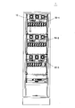
- the storage battery system 1 of the present embodiment includes a rack 10 and a plurality of battery shelf assemblies 50-1 to 50-3 (hereinafter simply referred to as “battery shelf assemblies” accommodated in the rack 10. 50 ”).
- battery shelf assemblies 50-1 to 50-3 are arranged in three upper and lower stages.
- a controller 70 is provided below these battery shelf assemblies 50.
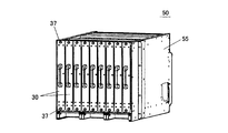
- the battery shelf assembly 50 means a state in which a plurality of battery units 30 are mounted on a battery shelf 55 that is a housing case (details will be described later).
- Each of the battery shelf assemblies 50-1 to 50-3 has basically the same configuration, but the breaker unit 80 is replaced with a part of the battery unit 30 in the lowermost battery shelf assembly 50-3 among the three. Contained.
- the control unit 70 is for controlling the operation of the entire power storage system 1 and is composed of one or a plurality of control devices.
- the entire storage battery system 1 has some or all of the following functions: (A) supplying power from the battery unit 30 to a predetermined external device or system; (B) The battery unit 30 is charged by receiving external power supply. (C) The control unit 70 and the breaker unit 80 control the timing such as the start / end of charge / discharge, or monitor the state of each battery unit 30. (D) The function of the control unit 70 and the breaker unit 80 determines whether the temperature of one or a plurality of battery units 30 is within an appropriate range. (E) The function of the control unit 70 and the breaker unit 80 determines whether one or a plurality of battery units 30 are defective. (F) The function of the control unit 70 and the breaker unit 80 is used to determine how much the battery unit 30 has been used for a certain battery unit 30, and based on that, it is determined whether or not replacement is necessary.
- the number of battery units 30 is not particularly limited, but in this embodiment, a total of 24 battery units 30 are accommodated in three shelves, and all of them are electrically connected in series. Note that not all units need to be connected in series, and may be a combination of series connection and parallel connection.
- the rack 10 includes a base portion 21, struts 11 standing at the four corners thereof, and a top plate 22 attached to the top of the struts 11. It forms a rectangular parallelepiped accommodation space.
- the rack 10 also has inner struts 12 arranged on the left and right.
- the holding plates 15 ⁇ / b> L and 15 ⁇ / b> R are members for holding the battery shelf assembly 50, and are provided so as to hang substantially horizontally on the two adjacent inner columns 12. Both ends of the bottom surface of the battery shelf assembly 50 are held by the pair of holding plates 15L and 15R.
- pairs of holding plates 15L and 15R are provided at three locations in the vertical direction.
- the holding plates 15L and 15R are not limited, but may be metal members having an L-shaped cross section and sufficient rigidity. In this case, when the battery shelf 55 is attached, the shelf can be moved to the back side while sliding the shelf on the horizontal plane of the holding plates 15L and 15R. For example, screws and bolts may be used to fix the holding plates 15L and 15R to the inner support column 12.
- the inner support column 12 has a plurality of screw holes formed in the vertical direction so that the mounting positions (height direction) of the holding plates 15L and 15R can be adjusted. Thereby, it can respond to the size of various battery shelf assemblies. Depending on the size of the battery shelf assembly, the number of racks may be two or less or four or more.
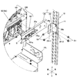
- FIG. 9 shows a power connector (floating connector) 180 constituted by a back connector member 181 and a mating connector member 191.
- the “floating structure” means that the other connector member is configured to be movable with respect to one connector member, so that the relative positional error between the connector members (for example, 1 mm or more, 2 mm or more, or 3 mm or more, or 5 mm or more).
- the “floating connector” means a connector having such a floating structure.
- the bracket member 17 is not limited to a plate shape as long as it has a function of holding at least the mating connector member 191, and may have any shape.
- the bracket member 17 itself may be configured to be movable in the front-rear direction, the left-right direction, and / or the up-down direction (details below).
- the bracket member 17 includes a support member 25 to which the mating connector member 191 is fixed, and a connecting piece 26 that connects the support member 25 to the support column 11 of the rack 10.
- the support member 25 is a long member extending in the left-right direction in this example.
- the support member 25 may be a metal member having a substantially U-shaped cross section.
- the connector member 191 is fixed to the support member 25 by screws or bolts S. In this state, a part of the connector member 191 (connection terminals 191p, 191q, etc.) protrudes to the back side through the opening 25a of the support member 25. It is in a state.
- the connecting piece 26 is provided at both ends of the support member 25 (only one is shown in FIG. 9).
- the connecting piece 20 is a metal member having an L-shaped cross section as an example, and has a flat surface 26-1 extending in the vertical and horizontal directions and a flat surface 26-2 extending in the vertical and front-back directions. Yes.
- the screw S1 is passed through the long hole 26a, and the tip end side of the screw S1 is screwed into the screw hole at the end of the support member 25. Since the longitudinal dimension / lateral dimension of the long hole 26a is sufficiently large with respect to the shaft diameter of the screw S1, the support member 25 can move in all directions in the vertical direction, the horizontal direction, and the diagonal direction even after the screw is tightened. You can move freely. In this case, the movable amount may be 1 mm to several mm.
- the flat surface 26-2 has two round holes 26b formed with a relatively large diameter.
- the screw S2 is passed through the round hole 26b, and the tip end side of the screw S2 is screwed into the screw hole formed in the column 11. Since the inner diameter of the round hole 26b is sufficiently large with respect to the shaft diameter of the screw S2, the connecting piece 26 (and thus the entire bracket member 17) can freely move in the vertical direction, the front-rear direction, and the like even after the screw is tightened. It can be moved.
- the movable amount may be 1 mm to several mm.
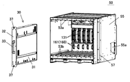
- the battery shelf assembly 50 includes a plurality of battery units 30 and a battery shelf 55 that accommodates the battery units 30.
- the battery unit 30 has a configuration in which a plurality of battery cells (not shown) are built in a thin and vertically long casing 31 as a whole.
- a front plate 32 is provided on the front surface side of the casing 31, and a handle 33 is provided at a substantially central portion of the plate 32.
- the upper end and the lower end of the front plate 32 are configured to be fixed to a part of the shelf 55 after the battery unit 30 is set in the battery shelf 55.
- the fixing screw 37 may be sufficient.
- the battery unit 30 may also have a sensor for detecting the temperature of the internal battery cell and an electronic circuit (not shown) for outputting the detection result to the outside.
- a power connector member (FIG. 8, described in detail later) and a signal connector member (not shown) are provided.
- the battery shelf 55 As shown in FIG. 5, the battery shelf 55 is formed in a box shape having an open front surface, and has both side surfaces, an upper surface, a lower surface, and a back surface. On both side surfaces, one fixing plate 57 (only the right side is shown) for fixing the battery shelf 55 to the rack 10 is provided.
- the battery unit 30 is inserted into the battery shelf 55 while sliding, and the upper surface in the battery shelf 55 is used for the guide (for insertion along the guide groove).
- guide members 53a and 53b are provided on the lower surface.
- the guide members 53a and 53b are not limited, but may be straight members arranged in parallel to each other.
- the electrical connection between the battery unit 30 and the battery shelf 55 is made by a connector having a floating structure (floating connector). This will be described below.
- FIG. 8 is a perspective view for explaining the structure of the floating connector.
- the connector 120 includes a fixed-side connector member 121 attached to the battery unit 30 side and a movable-side connector member 131 attached to the shelf 55 side.
- Each connector member 121, 131 may be made of resin as an example.
- the fixed connector member 121 is provided on the electrode terminal portion of the battery unit 30.
- the fixed connector member 121 has a base portion 122 and a recess 123 formed in the base portion 122.
- the concave portion 123 is a portion into which the plug portion 135 of the mating connector member 131 is inserted as described below, and a tapered portion 123 s is formed at the inlet portion of the concave portion 123.
- One hole (not shown) is formed in each of the upper end and the lower end of the base portion 122, and fixing screws are passed through the holes, and the fixed connector member 121 is fixed to the back surface of the battery unit 30.
- the movable connector member 131 has a base portion 132 and a plug portion 135 protruding therefrom.
- the outer shape of the plug portion 135 corresponds to the concave portion 123 of the fixed-side connector member 121.
- a tapered part 135s is formed at the tip of the plug part 135, whereby the plug part 135 is tapered.
- the plug part 135 is inserted into the recess 123 in the direction shown in the drawing, but the plug part 135 is inserted into the recess 123 in the upside down direction to prevent erroneous connection. It is also preferable that the structure is not possible.
- the floating structure of the connector 120 of the present embodiment is realized by forming the tapered portion 135s at the tip of the plug portion 135 and movably providing the movable connector member 131 as described below. That is, as shown in FIG. 8, a substantially U-shaped attachment portion 138 is formed at the upper end and the lower end of the base portion 132 of the movable connector member 131, and a gap 138 g inside the attachment portion 138 serves as the diameter of the fixing screw S. Has been made bigger than. With such a configuration, the movable-side connector member 131 is in a state of being temporarily fixed between the two fixing screws S. Therefore, the movable-side connector member 131 can freely move to some extent in all directions of the vertical direction, the horizontal direction, and the diagonal direction. The movable amount in this case may be, for example, about 1 mm to several mm although it depends on the size of the entire connector 120 and the size of the battery unit 30.
- the direction in which the movable connector member can move may be one or a combination thereof, instead of all the vertical, horizontal, and diagonal directions.
- the configuration that allows the movable connector member to move can be variously changed, and is not limited to the structure shown in FIG.
- the gap 138g of the attachment portion 138 may be a closed circular hole or a long hole. Further examples regarding the connector member will be described later.
- the movable-side connector member 131 may be configured to be movable not only in the vertical direction, the horizontal direction, and the diagonal direction in one plane, but also in the longitudinal direction (vertical direction, horizontal direction, diagonal direction, and One or a combination of the front and rear directions).
- the movable amount may be, for example, about 1 mm to several mm.
- the length of the neck portion (portion formed with a relatively large diameter) of the fixing screw S is longer than the thickness of the mounting portion 138, so that the movable-side connector member 131.
- it may be movable in the front-rear direction by 1 mm to several mm.
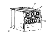
- the movable connector member 131 configured as described above is arranged on the back surface of the battery shelf 55 so as to be arranged in the horizontal direction. As shown in FIG. 7, a part of the movable side connector member 131 is exposed outside the back surface of the battery shelf 55, and the adjacent movable side connectors 131 are connected to each other by a flexible wiring 62.
- the flexible wiring 62 is obtained by providing connecting members at both ends of a strip-shaped conductive member. In the present embodiment, the flexible wiring 62 is attached obliquely so as to connect the upper end of one movable connector member 131 and the lower end of the other movable connector member 131.
- the battery units 30 are connected in series as described above.
- the electric power of the battery shelf assembly as a whole is taken out via a back connector member 181 provided at a power terminal portion (not shown) on the back of the battery shelf.
- the rear connector member 181 is the same as the fixed connector member 121 of FIG. In this example, the rear connector members 181 are respectively mounted sideways and arranged one by one side by side on the left and right.
- the mating connector member 191 is provided on the bracket member 17 of the rack 10.
- the connector member 191 is the same as the movable connector member 131 shown in FIG. With such a configuration, the battery shelf 55 and the rack 10 are also connected by the floating connector. Although not limited, the connector members 191 are connected in advance with a connection cord or the like.
- a signal connector 160 for exchanging electrical signals to the battery unit 50 will be described.
- this signal connector 160 for example, a known floating connector for electric equipment can be used, and a connector member 161 attached to the battery shelf 55 side and another connector member (not shown) attached to the battery unit 30 side. ).
- the power connector (connector member 131 in FIG. 5) and the signal connector (connector member 161 in FIG. 5) are arranged vertically with a predetermined interval. According to such a configuration, since the power line and the signal line are separated from each other, generation of power supply noise can be suppressed.
- a signal line (not shown) from the signal connector member 161 may be connected to an external control means or the like via an opening 55 a formed on the side surface of the battery shelf 55.
- the accommodation space may be formed in the bottom part of the battery shelf 55, for example, and BMU (control circuit: battery management unit) may be arrange
- a plurality of cooling fans 64 for cooling the battery unit 30 in the shelf may be provided in the upper part of the back surface of the battery shelf 55.
- the battery shelf assembly 50 configured as described above has the following functions: (A) The power corresponding to the number of the battery units 30 is output, and the battery units 30 are charged at a predetermined timing. (B) Input / output of electrical signals to / from each battery unit 30 is performed via signal lines (not shown). (C) The cooling fan 64 is driven at a predetermined timing for cooling the battery unit 30.
- the rack 10 (FIG. 4) is assembled at the planned installation position of the power storage system 1, and the battery shelf 55 is attached to the rack 10 before the battery unit 30 is mounted as an example.
- the battery shelf 55 is attached by moving the battery shelf 55 from the front side of the rack to the back side, connecting the back connector member 181 of the battery shelf 55 and the mating connector member 191 on the rack side, and then fixing members ( The battery shelf 55 and the rack 10 are fixed with screws, bolts, and the like.
- the bracket member 17 is configured to be movable at least several millimeters in the front-rear direction. Therefore, for example, even if the position of the battery shelf 55 is slightly shifted rearward from the predetermined position, the bracket member 17 is displaced rearward so that the error can be absorbed and the rear connector member 181 and the counterpart side can be satisfactorily absorbed. Connection with the connector member 191 can be performed. That is, in the present embodiment, the movable structure of the floating connector 180 and the bracket member 17 can absorb the position error of the connector members 181 and 191 in a complex manner.
- the battery units 30 are mounted one by one on the fixed battery shelf 55. Specifically, the operator holds the battery unit 30 and inserts it while sliding it into the battery shelf 55. At this time, since the guide members 53a and 53b are formed on the upper surface and the lower surface in the shelf, the battery unit 30 can be inserted straight by the guide action.
- the floating connector 120 absorbs the error and the connector is connected properly. It can be performed.
- the signal connector 160 can be connected well while absorbing errors by the action of the floating structure.
- the other two battery shelf assemblies 50 can be assembled in the same manner as described above (for the battery shelf assembly 50-3, the breaker unit 80 is attached). After all three battery shelf assemblies 50 are assembled, predetermined electrical wiring is performed to complete the power storage system 1 of the present embodiment. In addition, as predetermined electrical wiring, connecting the signal line from each battery shelf 50 to the control part 75 fixed to the rack 10 is mentioned.
- the power connector 120 and the signal connector 160 are connected simply by sliding the battery unit 30 into the battery shelf 55 and inserting the battery unit 30 into the battery shelf 55. Done. This eliminates the need for the operator to connect the battery units 30 with cables or the like. Moreover, even if it is necessary to replace and repair a predetermined battery unit 30, it is possible to remove and remove the fixing unit 37, etc., and then pull the battery unit 30 forward. The property is also good.
- the floating connector 120 (see FIG. 8) as exemplified in the present embodiment, it is possible to absorb errors in positions in all directions in the vertical direction, the horizontal direction, and the diagonal direction.
- the movable connector member 131 When the fixed connector member 121 is provided in the battery unit 30 and the movable connector member 131 is provided in the battery shelf 55, there are the following advantages. That is, since the movable connector member 131 needs to have a floating structure, the movable connector member 131 is usually larger in size than the fixed connector member 121. Accordingly, the battery unit 30 as a whole can be reduced in size by providing the fixed-side connector member 131 that can be relatively reduced in size on the battery unit 30 side.
- the fixed-side connector member 121 When the fixed-side connector member 121 is provided with a recess 123 into which the plug portion 135 of the movable-side connector member 131 is inserted, a structure portion such as the plug portion 135 does not protrude from the battery unit 30. The handleability of the unit 30 is improved.
- the plug portion 135 is formed on the movable connector member 131.
- the plug portion (projecting portion) is formed on the fixed connector member 121, and the plug portion 135 is formed in the concave portion of the movable connector member 131. It is good also as a structure inserted.
- the connection form of the battery is not limited to the series connection, and various connection forms may be employed such that at least a part of the battery units are connected in parallel or the shelves are connected in parallel.
- the number of racks 10 is not limited to one, and two or more racks 10 electrically connected in series or in parallel may be arranged. The racks 10 may be separated from each other or may be arranged adjacent to each other.
- the shapes of the support member 25 and the connecting piece 26 can be changed as appropriate.
- the support member 25 may have any material, shape, or the like as long as the support member 25 has sufficient rigidity so as not to be largely bent when the connector members are connected to each other.
- the connecting piece 26 is not limited to a metal member having an L-shaped cross section as shown in the figure, and can be made of various materials and shapes.
- the round hole 26b of the connecting piece 26 may be a long hole so that the bracket member 17 can be moved at least in the front-rear direction.
- An urging member for example, a spring or the like for urging the bracket member 17 forward may be provided.
- the present application also discloses the following inventions: 1. A plurality of battery units having storage batteries; A battery shelf that houses the battery unit, wherein the battery unit is configured to be slid into and removed from the battery shelf; and A power connector for connecting the battery unit and the battery shelf so that the power of the battery unit can be taken out; A battery shelf assembly comprising: The power connector is A first connector member provided on an electrode terminal portion of the battery unit; A second connector member provided on the battery shelf side and configured to connect to the first connector member; A battery shelf assembly having a floating structure for absorbing relative positional errors of the first and second connector members.
- the floating structure absorbs an error of (i) at least one of an up-down direction, a left-right direction, and an oblique direction; or (ii) at least one position in an up-down direction, a left-right direction, an oblique direction, and a front-rear direction.
- a battery shelf assembly as described above.
- the first connector member of the battery unit is a fixed connector member;
- the second connector member of the battery shelf is a movable connector member;
- a plug portion is formed on the movable connector member, A concave portion into which the plug portion is inserted is formed in the fixed-side connector member, A taper portion is formed at least at the tip of the plug portion, A battery shelf assembly as described above.
- the battery unit has an electronic circuit, further, A signal connector for enabling an electrical signal to be exchanged with the electronic circuit;
- the signal connector has a first signal connector member provided on the battery unit, a second signal connector member provided on the battery shelf side, and an error in relative positions of both connector members.
- the electrode terminal part for taking out the electric power as the whole battery shelf assembly is formed in the shelf back,
- At least one battery shelf assembly as described above; A rack in which the battery shelf assembly is housed; Power storage system with
- the battery shelf assembly includes a first connector member provided on an electrode terminal portion of the battery unit, a second connector member provided on the battery shelf side, and a relative relationship between the first and second connector members.
- a power connector having a floating structure for absorbing errors in various positions, (A) inserting the battery unit while sliding it into the battery shelf; (B) connecting the first connector member and the second connector member while absorbing an error in the relative positions of the first and second connector members with the power connector; A method for assembling a battery shelf assembly.
Landscapes
- Chemical & Material Sciences (AREA)
- Chemical Kinetics & Catalysis (AREA)
- Electrochemistry (AREA)
- General Chemical & Material Sciences (AREA)
- Engineering & Computer Science (AREA)
- Microelectronics & Electronic Packaging (AREA)
- Manufacturing & Machinery (AREA)
- Battery Mounting, Suspending (AREA)
- Details Of Connecting Devices For Male And Female Coupling (AREA)
Abstract
Description
1.蓄電池を有する複数の電池ユニットと、
前記電池ユニットを収容する電池シェルフであって、前記電池ユニットが当該電池シェルフ内にスライドして着脱されるように構成されている電池シェルフと、
前記電池ユニットと電池シェルフとを接続し前記電池ユニットの電力を外部に取り出せるようにする電力用コネクタと、
を備える電池シェルフアセンブリであって、
前記電力用コネクタは、
前記電池ユニットの電極端子部に設けられた第1のコネクタ部材と、
前記電池シェルフ側に設けられ前記第1のコネクタ部材と接続するように構成された第2のコネクタ部材と、
第1および第2のコネクタ部材の相対的な位置の誤差を吸収するためのフローティング構造とを有している、電池シェルフアセンブリ。
「電池ユニット」とは、充放電可能な蓄電池(電池セル)を1つ又は複数有するものであって「電池モジュール」等と呼ばれることもある。
「電池シェルフ」とは、電池ユニットを収容するためのケースであって、典型的なものとしては、電池ユニットを挿入するための開口部を一部に有する箱型のケースである。なお、電池ユニットを収容、保持する機能を有するものであれば、箱型以外の様々な形態も可能である。
〔全体構成〕
図1~図3に示すように、本実施形態の蓄電池システム1は、ラック10と、そのラック10に収容される複数の電池シェルフアセンブリ50-1~50-3(以下、単に「電池シェルフアセンブリ50」ともいう)を備えている。この例では、3つの電池シェルフアセンブリ50-1~50-3が上下三段に配置されている。これらの電池シェルフアセンブリ50の下方に制御部70が設けられている。
(a)電池ユニット30からの電力を外部の所定の機器またはシステムに供給する、
(b)外部からの電力供給を受けて各電池ユニット30の充電を行う、
(c)制御部70やブレーカユニット80によって、充放電の開始・終了等のタイミングを制御したり、各電池ユニット30の状態を監視したりする。
(d)制御部70やブレーカユニット80の機能により、1つまたは複数の電池ユニット30の温度が適正範囲内か否かを判定する、
(e)制御部70やブレーカユニット80の機能により、1つまたは複数の電池ユニット30に欠陥が生じているか否かを判定する、
(f)制御部70やブレーカユニット80の機能により、ある電池ユニット30について当該電池ユニットがどの程度使用されたかを判定し、それに基づき交換が必要が否かを判定する。
ラック10は、図3および図4に示すように、基台部21と、その四隅部に立てられた支柱11と、支柱11の上部に取り付けられた天板22とを備え、全体として略縦長直方体の収容スペースを形成するものである。ラック10は、また、左右に2本ずつ配置された内側支柱12を有している。保持プレート15L、15Rは、電池シェルフアセンブリ50を保持するための部材であって、隣接する2本の内側支柱12に略水平に架かるように設けられている。一対の保持プレート15L、15Rによって電池シェルフアセンブリ50の底面両端部が保持される。
以下、電池シェルフアセンブリ50の構成について詳細に説明する。
(a)電池ユニット30の個数に応じた電力を出力する、また、所定のタイミングで電池ユニット30の充電を行う、
(b)信号ライン(不図示)を介して各電池ユニット30に対する電気的信号の入出力が行われる、
(c)電池ユニット30の冷却のために所定のタイミングで冷却ファン64の駆動が行われる。
次に、本実施形態の蓄電システム1の組立方法について説明する。なお、下記する組立方法は本発明の一例に過ぎず、その手順等によって本発明が何ら限定されるものではない。
以上、本発明の一形態について図面を参照して説明したが、本発明は上記に限定されるものではなく種々変更可能である:
(a)上記例では複数の電池ユニット30が横方向に並んで配置される構成を示したが、複数の電池ユニットが縦方向に積層されるように配置されるもの、あるいはマトリクス状に配置されるもの等であってもよい。
(b)上記例では電力用のコネクタと信号用のコネクタの両方をフローティングコネクタとした構成を示したが、いずれか一方のみをフローティングコネクタとしてもよい。
(c)上記例ではフローティングコネクタの可動側コネクタ部材をシェルフ側に配置し、固定側コネクタ部材を電池ユニット側に配置したが、逆に、可動側コネクタ部材を電池ユニット側に配置し、固定側コネクタ部材をシェルフ側に配置してもよい。このような変更は、電力用コネクタおよび信号用コネクタの一方または両方に適用可能である。
(e)電池の接続形態は直列接続に限らず、電池ユニットの少なくとも一部が並列に接続される、または、シェルフ同士が並列に接続されるといったように種々の接続形態を採用しうる。
(f)図7の背面コネクタ部材181に関し、横置きではなく縦置きで設けられていてもよい。
(g)ラック10は1つに限らず、互いに直列または並列に電気的接続された2以上のラック10が配置されていてもよい。ラック10同士は離れていてもよいし、隣接して配置されてもよい。
(i)ブラケット部材17を少なくとも前後方向に移動できるようにするために、連結片26の丸孔26bを長孔としてもよい。
(j)ブラケット部材17を前方に付勢するための付勢部材(例えばスプリング等)が設けられていてもよい。
1.蓄電池を有する複数の電池ユニットと、
前記電池ユニットを収容する電池シェルフであって、前記電池ユニットが当該電池シェルフ内にスライドして着脱されるように構成されている電池シェルフと、
前記電池ユニットと電池シェルフとを接続し前記電池ユニットの電力を外部に取り出せるようにする電力用コネクタと、
を備える電池シェルフアセンブリであって、
前記電力用コネクタは、
前記電池ユニットの電極端子部に設けられた第1のコネクタ部材と、
前記電池シェルフ側に設けられ前記第1のコネクタ部材と接続するように構成された第2のコネクタ部材と、
第1および第2のコネクタ部材の相対的な位置の誤差を吸収するためのフローティング構造とを有している、電池シェルフアセンブリ。
前記電池シェルフの第2のコネクタ部材が可動側コネクタ部材である、
上記記載の電池シェルフアセンブリ。
固定側コネクタ部材にそのプラグ部が挿入される凹部が形成され、
少なくとも前記プラグ部の先端にテーパ部が形成されている、
上記記載の電池シェルフアセンブリ。
さらに、
前記電子回路と電気的信号をやり取りできるようにするための信号用コネクタを備え、
該信号用コネクタが、前記電池ユニットに設けられた第1の信号用コネクタ部材、前記電池シェルフ側に設けられた第2の信号用コネクタ部材、および、両コネクタ部材の相対的な位置の誤差を吸収するためのフローティング構造を有している、
上記記載の電池シェルフアセンブリ。
電池シェルフアセンブリ全体としての電力を取り出すための電極端子部がシェルフ背面に形成されており、
該電極端子部に、相手方コネクタ部材と協働してフローティングコネクタを構成する背面コネクタ部材が設けられている、上記記載の電池シェルフアセンブリ。
該電池シェルフアセンブリが収容されるラックと、
を備えた蓄電システム。
前記電池シェルフアセンブリは、前記電池ユニットの電極端子部に設けられた第1のコネクタ部材、前記電池シェルフ側に設けられた第2のコネクタ部材、および、第1および第2のコネクタ部材の相対的な位置の誤差を吸収するためのフローティング構造を有する電力用コネクタを有し、
(a)電池ユニットを電池シェルフ内にスライドさせながら挿入するステップと、
(b)第1および第2のコネクタ部材の相対的な位置の誤差を前記電力用コネクタで吸収しながら第1のコネクタ部材と第2のコネクタ部材とを接続するステップと、
を有する電池シェルフアセンブリの組立方法。
10 ラック
11 支柱
12 内側支柱
15L、15R 保持プレート
17 ブラケット部材
21 基台部
22 天板
25 支持部材
25a 開口部
26 連結片
26a 長孔
26b 丸孔
30 電池ユニット
31 筺体
32 前面プレート
33 ハンドル
37 固定ネジ
50 電池シェルフアセンブリ
53a、53b ガイド部材
55 電池シェルフ
62 可撓性配線
64 冷却ファン
70 制御部
80 ブレーカユニット
120 電力用コネクタ
121 固定側コネクタ部材
122 ベース部
123 凹部
123s テーパ部
131 可動側コネクタ部材
132 ベース部
135 プラグ部
135s テーパ部
138 取付け部
138g ギャップ
160 信号用コネクタ
161 コネクタ部材
180 電力用コネクタ
181 背面コネクタ部材
191 相手側コネクタ部材
191p、191q 接続端子
S 固定ネジ
Claims (10)
- 蓄電池を有する複数の電池ユニットと、
前記電池ユニットを収容する電池シェルフであって、前記電池ユニットが当該電池シェルフ内にスライドして着脱されるように構成されている電池シェルフと、
前記電池ユニットと電池シェルフとを接続し前記電池ユニットの電力を外部に取り出せるようにする電力用コネクタと、
を備える電池シェルフアセンブリであって、
前記電力用コネクタは、
前記電池ユニットの電極端子部に設けられた第1のコネクタ部材と、
前記電池シェルフ側に設けられ前記第1のコネクタ部材と接続するように構成された第2のコネクタ部材と、
第1および第2のコネクタ部材の相対的な位置の誤差を吸収するためのフローティング構造とを有している、電池シェルフアセンブリ。 - 前記フローティング構造が、(i)上下方向、左右方向、および斜め方向の少なくとも1つ、もしくは、(ii)上下方向、左右方向、斜め方向、および前後方向の少なくとも1つの位置の誤差を吸収する、請求項1に記載の電池シェルフアセンブリ。
- 前記電池ユニットの第1のコネクタ部材が固定側コネクタ部材であり、
前記電池シェルフの第2のコネクタ部材が可動側コネクタ部材である、
請求項1または2に記載の電池シェルフアセンブリ。 - 可動側コネクタ部材にプラグ部が形成され、
固定側コネクタ部材にそのプラグ部が挿入される凹部が形成され、
少なくとも前記プラグ部の先端にテーパ部が形成されている、
請求項3に記載の電池シェルフアセンブリ。 - 前記電池ユニットが電子回路を有するものであって、
さらに、
前記電子回路と電気的信号をやり取りできるようにするための信号用コネクタを備え、
該信号用コネクタが、前記電池ユニットに設けられた第1の信号用コネクタ部材、前記電池シェルフ側に設けられた第2の信号用コネクタ部材、および、両コネクタ部材の相対的な位置の誤差を吸収するためのフローティング構造を有している、
請求項1~4のいずれか一項に記載の電池シェルフアセンブリ。 - 前記信号用コネクタと前記電力用コネクタとが所定の間隔をあけて配置されている、請求項5に記載の電池シェルフアセンブリ。
- さらに、
電池シェルフアセンブリ全体としての電力を取り出すための電極端子部がシェルフ背面に形成されており、
該電極端子部に、相手方コネクタ部材と協働してフローティングコネクタを構成する背面コネクタ部材が設けられている、請求項1~6のいずれか一項に記載の電池シェルフアセンブリ。 - 前記背面コネクタ部材が固定側コネクタ部材である、請求項7に記載の電池シェルフアセンブリ。
- 少なくとも1つの、請求項1~8のいずれか一項に記載の電池シェルフアセンブリと、
該電池シェルフアセンブリが収容されるラックと、
を備えた蓄電システム。 - 蓄電池を有する電池ユニットを電池シェルフに装着して電池シェルフアセンブリを組み立てる方法あって、
前記電池シェルフアセンブリは、前記電池ユニットの電極端子部に設けられた第1のコネクタ部材、前記電池シェルフ側に設けられた第2のコネクタ部材、および、第1および第2のコネクタ部材の相対的な位置の誤差を吸収するためのフローティング構造を有する電力用コネクタを有し、
(a)電池ユニットを電池シェルフ内にスライドさせながら挿入するステップと、
(b)第1および第2のコネクタ部材の相対的な位置の誤差を前記電力用コネクタで吸収しながら第1のコネクタ部材と第2のコネクタ部材とを接続するステップと、
を有する電池シェルフアセンブリの組立方法。
Priority Applications (3)
| Application Number | Priority Date | Filing Date | Title |
|---|---|---|---|
| JP2014545704A JPWO2014073524A1 (ja) | 2012-11-06 | 2013-11-05 | 電池シェルフアセンブリ、蓄電システム、および電池シェルフアセンブリの組立方法 |
| EP13853477.1A EP2919293A4 (en) | 2012-11-06 | 2013-11-05 | BATTERY SURFACE ARRANGEMENT, ENERGY STORAGE SYSTEM AND ASSEMBLY METHOD OF A BATTERY SURFACE ARRANGEMENT |
| US14/440,577 US20150303419A1 (en) | 2012-11-06 | 2013-11-05 | Battery Shelf Assembly, Power Storage System, and Assemblying Method of Battery Shelf Assembly |
Applications Claiming Priority (2)
| Application Number | Priority Date | Filing Date | Title |
|---|---|---|---|
| JP2012244925 | 2012-11-06 | ||
| JP2012-244925 | 2012-11-06 |
Publications (1)
| Publication Number | Publication Date |
|---|---|
| WO2014073524A1 true WO2014073524A1 (ja) | 2014-05-15 |
Family
ID=50684627
Family Applications (1)
| Application Number | Title | Priority Date | Filing Date |
|---|---|---|---|
| PCT/JP2013/079875 Ceased WO2014073524A1 (ja) | 2012-11-06 | 2013-11-05 | 電池シェルフアセンブリ、蓄電システム、および電池シェルフアセンブリの組立方法 |
Country Status (4)
| Country | Link |
|---|---|
| US (1) | US20150303419A1 (ja) |
| EP (1) | EP2919293A4 (ja) |
| JP (1) | JPWO2014073524A1 (ja) |
| WO (1) | WO2014073524A1 (ja) |
Cited By (9)
| Publication number | Priority date | Publication date | Assignee | Title |
|---|---|---|---|---|
| JP2018133288A (ja) * | 2017-02-17 | 2018-08-23 | 住友重機械搬送システム株式会社 | 蓄電デバイスの搬送トレー、検査ラック |
| WO2019022098A1 (ja) * | 2017-07-27 | 2019-01-31 | 三洋電機株式会社 | 電池パック及びその製造方法 |
| JP2019516229A (ja) * | 2016-04-20 | 2019-06-13 | コルヴァス エナジー インコーポレイテッド | 電力及び冷却下部構造体付きバックプレーン組立体 |
| JP2020524369A (ja) * | 2018-03-12 | 2020-08-13 | エルジー・ケム・リミテッド | フック構造が適用されたエネルギー貯蔵装置及びこれを含むエネルギー貯蔵システム |
| JP2021005500A (ja) * | 2019-06-26 | 2021-01-14 | 株式会社Gsユアサ | 蓄電装置 |
| WO2021107069A1 (ja) * | 2019-11-29 | 2021-06-03 | 本田技研工業株式会社 | 保持装置 |
| JP2023516735A (ja) * | 2020-03-05 | 2023-04-20 | 3 エムイー テクノロジー プロプライエタリー リミテッド | バッテリのための装置、システム、及び方法 |
| JP2023530399A (ja) * | 2020-12-07 | 2023-07-18 | エルジー エナジー ソリューション リミテッド | ボード型のessバッテリーパック |
| US12170385B2 (en) | 2020-06-11 | 2024-12-17 | Lg Energy Solution, Ltd. | Modular battery pack for energy storage system |
Families Citing this family (13)
| Publication number | Priority date | Publication date | Assignee | Title |
|---|---|---|---|---|
| ITUB20159187A1 (it) * | 2015-12-24 | 2017-06-24 | Archimede Energia S P A | Sistema di accumulo ad elevata densita energetica |
| WO2017152356A1 (en) * | 2016-03-08 | 2017-09-14 | Schneider Electric It Corporation | Rack power system and method |
| US10193112B2 (en) | 2016-04-08 | 2019-01-29 | Lockheed Martin Energy, Llc | Modular energy storage component enclosure |
| IT201600093103A1 (it) * | 2016-09-15 | 2018-03-15 | Ansaldo Sts Spa | Struttura estraibile di alloggiamento per componenti elettronici |
| US10130000B2 (en) * | 2016-10-11 | 2018-11-13 | Abb Schweiz Ag | Power connector for electronic equipment supported by a rack assembly |
| US10062977B2 (en) * | 2016-10-14 | 2018-08-28 | Inevit Llc | Module-to-module power connector between battery modules of an energy storage system and arrangement thereof |
| KR101799540B1 (ko) | 2017-01-23 | 2017-11-20 | (주)알씨디에이치 | 원전 dc비상전원 공급 장치용 전지모듈 |
| DE102017207691B4 (de) * | 2017-05-08 | 2026-03-12 | Fritz GmbH & Co. KG | Stationäres Lagersystem für Batterien |
| US10581038B2 (en) | 2017-12-18 | 2020-03-03 | Irobot Corporation | Battery assembly for autonomous mobile robot |
| US10709034B2 (en) * | 2018-02-21 | 2020-07-07 | Google Llc | Supporting rack-mounted computing devices |
| CN111129409A (zh) * | 2020-01-02 | 2020-05-08 | 昆兰新能源技术常州有限公司 | 一种新型大规模电力储能装置 |
| FR3108229B1 (fr) * | 2020-03-11 | 2022-03-25 | Alstom Transp Tech | Baie électronique et véhicule équipé d’une telle baie |
| USD1078459S1 (en) | 2021-06-25 | 2025-06-10 | Caterpillar Inc. | Bracket |
Citations (9)
| Publication number | Priority date | Publication date | Assignee | Title |
|---|---|---|---|---|
| JP2002117821A (ja) * | 2000-10-04 | 2002-04-19 | Nippon Telegr & Teleph Corp <Ntt> | 蓄電池収納キャビネット及び蓄電池収納接続方法 |
| JP2003309935A (ja) * | 2002-04-16 | 2003-10-31 | Hitachi Ltd | 直流バックアップ電源装置 |
| JP2004231024A (ja) * | 2003-01-30 | 2004-08-19 | Kawasaki Heavy Ind Ltd | 鉄道車両用バッテリー箱 |
| JP2006351311A (ja) * | 2005-06-15 | 2006-12-28 | Nippon Telegr & Teleph Corp <Ntt> | バックアップ電源システム |
| JP2008276991A (ja) * | 2007-04-25 | 2008-11-13 | Souriau Japan Kk | 電気コネクタ |
| JP2010055973A (ja) * | 2008-08-29 | 2010-03-11 | Hitachi Ltd | 鉄道車両の電池箱及び鉄道車両 |
| JP2012009309A (ja) | 2010-06-25 | 2012-01-12 | Sanyo Electric Co Ltd | 蓄電システム |
| WO2012132134A1 (ja) * | 2011-03-31 | 2012-10-04 | 三洋電機株式会社 | ラック型の電源装置及び脱着コネクタを備える電池パック |
| JP2013140710A (ja) * | 2012-01-04 | 2013-07-18 | Japan Aviation Electronics Industry Ltd | 蓄電装置 |
Family Cites Families (3)
| Publication number | Priority date | Publication date | Assignee | Title |
|---|---|---|---|---|
| JP4673019B2 (ja) * | 2004-09-10 | 2011-04-20 | 日立コンピュータ機器株式会社 | 情報処理装置 |
| JP5308544B2 (ja) * | 2012-01-04 | 2013-10-09 | 日本航空電子工業株式会社 | 電池ユニット用のコネクタ、およびそれを備えた電池ユニット |
| IN2014MN02200A (ja) * | 2012-05-30 | 2015-09-11 | Moog Inc |
-
2013
- 2013-11-05 US US14/440,577 patent/US20150303419A1/en not_active Abandoned
- 2013-11-05 EP EP13853477.1A patent/EP2919293A4/en not_active Withdrawn
- 2013-11-05 JP JP2014545704A patent/JPWO2014073524A1/ja active Pending
- 2013-11-05 WO PCT/JP2013/079875 patent/WO2014073524A1/ja not_active Ceased
Patent Citations (9)
| Publication number | Priority date | Publication date | Assignee | Title |
|---|---|---|---|---|
| JP2002117821A (ja) * | 2000-10-04 | 2002-04-19 | Nippon Telegr & Teleph Corp <Ntt> | 蓄電池収納キャビネット及び蓄電池収納接続方法 |
| JP2003309935A (ja) * | 2002-04-16 | 2003-10-31 | Hitachi Ltd | 直流バックアップ電源装置 |
| JP2004231024A (ja) * | 2003-01-30 | 2004-08-19 | Kawasaki Heavy Ind Ltd | 鉄道車両用バッテリー箱 |
| JP2006351311A (ja) * | 2005-06-15 | 2006-12-28 | Nippon Telegr & Teleph Corp <Ntt> | バックアップ電源システム |
| JP2008276991A (ja) * | 2007-04-25 | 2008-11-13 | Souriau Japan Kk | 電気コネクタ |
| JP2010055973A (ja) * | 2008-08-29 | 2010-03-11 | Hitachi Ltd | 鉄道車両の電池箱及び鉄道車両 |
| JP2012009309A (ja) | 2010-06-25 | 2012-01-12 | Sanyo Electric Co Ltd | 蓄電システム |
| WO2012132134A1 (ja) * | 2011-03-31 | 2012-10-04 | 三洋電機株式会社 | ラック型の電源装置及び脱着コネクタを備える電池パック |
| JP2013140710A (ja) * | 2012-01-04 | 2013-07-18 | Japan Aviation Electronics Industry Ltd | 蓄電装置 |
Non-Patent Citations (1)
| Title |
|---|
| See also references of EP2919293A4 |
Cited By (20)
| Publication number | Priority date | Publication date | Assignee | Title |
|---|---|---|---|---|
| JP2019516229A (ja) * | 2016-04-20 | 2019-06-13 | コルヴァス エナジー インコーポレイテッド | 電力及び冷却下部構造体付きバックプレーン組立体 |
| JP7088907B2 (ja) | 2016-04-20 | 2022-06-21 | コルヴァス エナジー インコーポレイテッド | 電力及び冷却下部構造体付きバックプレーン組立体 |
| JP2018133288A (ja) * | 2017-02-17 | 2018-08-23 | 住友重機械搬送システム株式会社 | 蓄電デバイスの搬送トレー、検査ラック |
| WO2019022098A1 (ja) * | 2017-07-27 | 2019-01-31 | 三洋電機株式会社 | 電池パック及びその製造方法 |
| JPWO2019022098A1 (ja) * | 2017-07-27 | 2020-05-28 | 三洋電機株式会社 | 電池パック及びその製造方法 |
| US11532847B2 (en) | 2017-07-27 | 2022-12-20 | Sanyo Electric Co., Ltd. | Battery pack and production method for same |
| JP7160809B2 (ja) | 2017-07-27 | 2022-10-25 | 三洋電機株式会社 | 電池パック及びその製造方法 |
| US11522245B2 (en) | 2018-03-12 | 2022-12-06 | Lg Energy Solution, Ltd. | Energy storage apparatus using hook structure, and energy storage system comprising energy storage apparatus |
| JP2020524369A (ja) * | 2018-03-12 | 2020-08-13 | エルジー・ケム・リミテッド | フック構造が適用されたエネルギー貯蔵装置及びこれを含むエネルギー貯蔵システム |
| JP7094311B2 (ja) | 2018-03-12 | 2022-07-01 | エルジー エナジー ソリューション リミテッド | フック構造が適用されたエネルギー貯蔵装置及びこれを含むエネルギー貯蔵システム |
| JP2021005500A (ja) * | 2019-06-26 | 2021-01-14 | 株式会社Gsユアサ | 蓄電装置 |
| JP7392303B2 (ja) | 2019-06-26 | 2023-12-06 | 株式会社Gsユアサ | 蓄電装置 |
| CN114747073A (zh) * | 2019-11-29 | 2022-07-12 | 本田技研工业株式会社 | 保持装置 |
| JPWO2021107069A1 (ja) * | 2019-11-29 | 2021-06-03 | ||
| WO2021107069A1 (ja) * | 2019-11-29 | 2021-06-03 | 本田技研工業株式会社 | 保持装置 |
| JP7765289B2 (ja) | 2019-11-29 | 2025-11-06 | 本田技研工業株式会社 | 保持装置 |
| JP2023516735A (ja) * | 2020-03-05 | 2023-04-20 | 3 エムイー テクノロジー プロプライエタリー リミテッド | バッテリのための装置、システム、及び方法 |
| US12170385B2 (en) | 2020-06-11 | 2024-12-17 | Lg Energy Solution, Ltd. | Modular battery pack for energy storage system |
| JP2023530399A (ja) * | 2020-12-07 | 2023-07-18 | エルジー エナジー ソリューション リミテッド | ボード型のessバッテリーパック |
| JP7549047B2 (ja) | 2020-12-07 | 2024-09-10 | エルジー エナジー ソリューション リミテッド | ボード型のessバッテリーパック |
Also Published As
| Publication number | Publication date |
|---|---|
| EP2919293A4 (en) | 2016-06-15 |
| US20150303419A1 (en) | 2015-10-22 |
| JPWO2014073524A1 (ja) | 2016-09-08 |
| EP2919293A1 (en) | 2015-09-16 |
Similar Documents
| Publication | Publication Date | Title |
|---|---|---|
| JP6108487B2 (ja) | ラック構造、蓄電システム、およびラック構造の組立方法 | |
| JPWO2014073524A1 (ja) | 電池シェルフアセンブリ、蓄電システム、および電池シェルフアセンブリの組立方法 | |
| JP5247896B2 (ja) | 蓄電装置 | |
| CN110088935B (zh) | 机架型电源装置 | |
| TWI485946B (zh) | 蓄電裝置 | |
| JP6782435B2 (ja) | 蓄電装置 | |
| JP5590079B2 (ja) | 電池用配線モジュール | |
| JP6112066B2 (ja) | モジュール式電子機器連結用収納部材 | |
| JP6883772B2 (ja) | コネクタ構造及び蓄電装置 | |
| JP6330353B2 (ja) | 配線モジュール | |
| JP2017073270A (ja) | 蓄電池ユニット及び蓄電池収容装置 | |
| JP5834857B2 (ja) | 電池モジュール接続装置 | |
| US11450914B2 (en) | Storage battery unit | |
| KR102092917B1 (ko) | 배터리 팩 및 이러한 배터리 팩을 포함하는 전력 저장 장치 | |
| CN110679003A (zh) | 蓄电池单元 | |
| KR102088974B1 (ko) | 배터리 모듈, 이러한 배터리 모듈을 포함하는 배터리 팩 및 이러한 배터리 팩을 포함하는 전력 저장 장치 | |
| JP6627286B2 (ja) | 蓄電装置 | |
| TWI382577B (zh) | The battery module setting structure of the generator starting power supply unit | |
| KR102252181B1 (ko) | 전지모듈과 회로 부재를 조립하기 위한 지그 | |
| JP2017016886A (ja) | 蓄電装置 | |
| JP2017016887A (ja) | 蓄電装置 | |
| CN216794464U (zh) | 抽出式开关 | |
| JP6315173B2 (ja) | Dc接続箱 | |
| JP2019061843A (ja) | 蓄電池 |
Legal Events
| Date | Code | Title | Description |
|---|---|---|---|
| 121 | Ep: the epo has been informed by wipo that ep was designated in this application |
Ref document number: 13853477 Country of ref document: EP Kind code of ref document: A1 |
|
| ENP | Entry into the national phase |
Ref document number: 2014545704 Country of ref document: JP Kind code of ref document: A |
|
| WWE | Wipo information: entry into national phase |
Ref document number: 14440577 Country of ref document: US |
|
| NENP | Non-entry into the national phase |
Ref country code: DE |
|
| REEP | Request for entry into the european phase |
Ref document number: 2013853477 Country of ref document: EP |
|
| WWE | Wipo information: entry into national phase |
Ref document number: 2013853477 Country of ref document: EP |