WO2014077027A1 - 改質石炭の製造方法及び改質石炭製造装置 - Google Patents
改質石炭の製造方法及び改質石炭製造装置 Download PDFInfo
- Publication number
- WO2014077027A1 WO2014077027A1 PCT/JP2013/075199 JP2013075199W WO2014077027A1 WO 2014077027 A1 WO2014077027 A1 WO 2014077027A1 JP 2013075199 W JP2013075199 W JP 2013075199W WO 2014077027 A1 WO2014077027 A1 WO 2014077027A1
- Authority
- WO
- WIPO (PCT)
- Prior art keywords
- steam
- liquid
- coal
- separator
- oil
- Prior art date
- Legal status (The legal status is an assumption and is not a legal conclusion. Google has not performed a legal analysis and makes no representation as to the accuracy of the status listed.)
- Ceased
Links
Images


Classifications
-
- C—CHEMISTRY; METALLURGY
- C10—PETROLEUM, GAS OR COKE INDUSTRIES; TECHNICAL GASES CONTAINING CARBON MONOXIDE; FUELS; LUBRICANTS; PEAT
- C10L—FUELS NOT OTHERWISE PROVIDED FOR; NATURAL GAS; SYNTHETIC NATURAL GAS OBTAINED BY PROCESSES NOT COVERED BY SUBCLASSES C10G OR C10K; LIQUIFIED PETROLEUM GAS; USE OF ADDITIVES TO FUELS OR FIRES; FIRE-LIGHTERS
- C10L9/00—Treating solid fuels to improve their combustion
- C10L9/08—Treating solid fuels to improve their combustion by heat treatments, e.g. calcining
-
- B—PERFORMING OPERATIONS; TRANSPORTING
- B01—PHYSICAL OR CHEMICAL PROCESSES OR APPARATUS IN GENERAL
- B01D—SEPARATION
- B01D45/00—Separating dispersed particles from gases or vapours by gravity, inertia, or centrifugal forces
- B01D45/04—Separating dispersed particles from gases or vapours by gravity, inertia, or centrifugal forces by utilising inertia
- B01D45/08—Separating dispersed particles from gases or vapours by gravity, inertia, or centrifugal forces by utilising inertia by impingement against baffle separators
- B01D45/10—Separating dispersed particles from gases or vapours by gravity, inertia, or centrifugal forces by utilising inertia by impingement against baffle separators which are wetted
-
- B—PERFORMING OPERATIONS; TRANSPORTING
- B01—PHYSICAL OR CHEMICAL PROCESSES OR APPARATUS IN GENERAL
- B01D—SEPARATION
- B01D47/00—Separating dispersed particles from gases, air or vapours by liquid as separating agent
-
- B—PERFORMING OPERATIONS; TRANSPORTING
- B02—CRUSHING, PULVERISING, OR DISINTEGRATING; PREPARATORY TREATMENT OF GRAIN FOR MILLING
- B02C—CRUSHING, PULVERISING, OR DISINTEGRATING IN GENERAL; MILLING GRAIN
- B02C11/00—Other auxiliary devices or accessories specially adapted for grain mills
- B02C11/08—Cooling, heating, ventilating, conditioning with respect to temperature or water content
-
- C—CHEMISTRY; METALLURGY
- C10—PETROLEUM, GAS OR COKE INDUSTRIES; TECHNICAL GASES CONTAINING CARBON MONOXIDE; FUELS; LUBRICANTS; PEAT
- C10L—FUELS NOT OTHERWISE PROVIDED FOR; NATURAL GAS; SYNTHETIC NATURAL GAS OBTAINED BY PROCESSES NOT COVERED BY SUBCLASSES C10G OR C10K; LIQUIFIED PETROLEUM GAS; USE OF ADDITIVES TO FUELS OR FIRES; FIRE-LIGHTERS
- C10L5/00—Solid fuels
- C10L5/02—Solid fuels such as briquettes consisting mainly of carbonaceous materials of mineral or non-mineral origin
- C10L5/04—Raw material of mineral origin to be used; Pretreatment thereof
-
- F—MECHANICAL ENGINEERING; LIGHTING; HEATING; WEAPONS; BLASTING
- F28—HEAT EXCHANGE IN GENERAL
- F28F—DETAILS OF HEAT-EXCHANGE AND HEAT-TRANSFER APPARATUS, OF GENERAL APPLICATION
- F28F7/00—Elements not covered by group F28F1/00, F28F3/00 or F28F5/00
-
- B—PERFORMING OPERATIONS; TRANSPORTING
- B01—PHYSICAL OR CHEMICAL PROCESSES OR APPARATUS IN GENERAL
- B01D—SEPARATION
- B01D1/00—Evaporating
- B01D1/28—Evaporating with vapour compression
- B01D1/2803—Special features relating to the vapour to be compressed
- B01D1/2818—Cleaning of the vapour before compression, e.g. demisters, washing of the vapour
-
- B—PERFORMING OPERATIONS; TRANSPORTING
- B01—PHYSICAL OR CHEMICAL PROCESSES OR APPARATUS IN GENERAL
- B01D—SEPARATION
- B01D1/00—Evaporating
- B01D1/30—Accessories for evaporators ; Constructional details thereof
- B01D1/305—Demister (vapour-liquid separation)
-
- B—PERFORMING OPERATIONS; TRANSPORTING
- B01—PHYSICAL OR CHEMICAL PROCESSES OR APPARATUS IN GENERAL
- B01D—SEPARATION
- B01D46/00—Filters or filtering processes specially modified for separating dispersed particles from gases or vapours
- B01D46/56—Filters or filtering processes specially modified for separating dispersed particles from gases or vapours with multiple filtering elements, characterised by their mutual disposition
- B01D46/62—Filters or filtering processes specially modified for separating dispersed particles from gases or vapours with multiple filtering elements, characterised by their mutual disposition connected in series
- B01D46/64—Filters or filtering processes specially modified for separating dispersed particles from gases or vapours with multiple filtering elements, characterised by their mutual disposition connected in series arranged concentrically or coaxially
-
- B—PERFORMING OPERATIONS; TRANSPORTING
- B01—PHYSICAL OR CHEMICAL PROCESSES OR APPARATUS IN GENERAL
- B01D—SEPARATION
- B01D47/00—Separating dispersed particles from gases, air or vapours by liquid as separating agent
- B01D47/06—Spray cleaning
-
- C—CHEMISTRY; METALLURGY
- C10—PETROLEUM, GAS OR COKE INDUSTRIES; TECHNICAL GASES CONTAINING CARBON MONOXIDE; FUELS; LUBRICANTS; PEAT
- C10G—CRACKING HYDROCARBON OILS; PRODUCTION OF LIQUID HYDROCARBON MIXTURES, e.g. BY DESTRUCTIVE HYDROGENATION, OLIGOMERISATION, POLYMERISATION; RECOVERY OF HYDROCARBON OILS FROM OIL-SHALE, OIL-SAND, OR GASES; REFINING MIXTURES MAINLY CONSISTING OF HYDROCARBONS; REFORMING OF NAPHTHA; MINERAL WAXES
- C10G1/00—Production of liquid hydrocarbon mixtures from oil-shale, oil-sand, or non-melting solid carbonaceous or similar materials, e.g. wood, coal
- C10G1/04—Production of liquid hydrocarbon mixtures from oil-shale, oil-sand, or non-melting solid carbonaceous or similar materials, e.g. wood, coal by extraction
- C10G1/045—Separation of insoluble materials
-
- C—CHEMISTRY; METALLURGY
- C10—PETROLEUM, GAS OR COKE INDUSTRIES; TECHNICAL GASES CONTAINING CARBON MONOXIDE; FUELS; LUBRICANTS; PEAT
- C10L—FUELS NOT OTHERWISE PROVIDED FOR; NATURAL GAS; SYNTHETIC NATURAL GAS OBTAINED BY PROCESSES NOT COVERED BY SUBCLASSES C10G OR C10K; LIQUIFIED PETROLEUM GAS; USE OF ADDITIVES TO FUELS OR FIRES; FIRE-LIGHTERS
- C10L2290/00—Fuel preparation or upgrading, processes or apparatus therefore, comprising specific process steps or apparatus units
- C10L2290/06—Heat exchange, direct or indirect
-
- C—CHEMISTRY; METALLURGY
- C10—PETROLEUM, GAS OR COKE INDUSTRIES; TECHNICAL GASES CONTAINING CARBON MONOXIDE; FUELS; LUBRICANTS; PEAT
- C10L—FUELS NOT OTHERWISE PROVIDED FOR; NATURAL GAS; SYNTHETIC NATURAL GAS OBTAINED BY PROCESSES NOT COVERED BY SUBCLASSES C10G OR C10K; LIQUIFIED PETROLEUM GAS; USE OF ADDITIVES TO FUELS OR FIRES; FIRE-LIGHTERS
- C10L2290/00—Fuel preparation or upgrading, processes or apparatus therefore, comprising specific process steps or apparatus units
- C10L2290/08—Drying or removing water
-
- C—CHEMISTRY; METALLURGY
- C10—PETROLEUM, GAS OR COKE INDUSTRIES; TECHNICAL GASES CONTAINING CARBON MONOXIDE; FUELS; LUBRICANTS; PEAT
- C10L—FUELS NOT OTHERWISE PROVIDED FOR; NATURAL GAS; SYNTHETIC NATURAL GAS OBTAINED BY PROCESSES NOT COVERED BY SUBCLASSES C10G OR C10K; LIQUIFIED PETROLEUM GAS; USE OF ADDITIVES TO FUELS OR FIRES; FIRE-LIGHTERS
- C10L2290/00—Fuel preparation or upgrading, processes or apparatus therefore, comprising specific process steps or apparatus units
- C10L2290/18—Spraying or sprinkling
-
- C—CHEMISTRY; METALLURGY
- C10—PETROLEUM, GAS OR COKE INDUSTRIES; TECHNICAL GASES CONTAINING CARBON MONOXIDE; FUELS; LUBRICANTS; PEAT
- C10L—FUELS NOT OTHERWISE PROVIDED FOR; NATURAL GAS; SYNTHETIC NATURAL GAS OBTAINED BY PROCESSES NOT COVERED BY SUBCLASSES C10G OR C10K; LIQUIFIED PETROLEUM GAS; USE OF ADDITIVES TO FUELS OR FIRES; FIRE-LIGHTERS
- C10L2290/00—Fuel preparation or upgrading, processes or apparatus therefore, comprising specific process steps or apparatus units
- C10L2290/46—Compressors or pumps
-
- C—CHEMISTRY; METALLURGY
- C10—PETROLEUM, GAS OR COKE INDUSTRIES; TECHNICAL GASES CONTAINING CARBON MONOXIDE; FUELS; LUBRICANTS; PEAT
- C10L—FUELS NOT OTHERWISE PROVIDED FOR; NATURAL GAS; SYNTHETIC NATURAL GAS OBTAINED BY PROCESSES NOT COVERED BY SUBCLASSES C10G OR C10K; LIQUIFIED PETROLEUM GAS; USE OF ADDITIVES TO FUELS OR FIRES; FIRE-LIGHTERS
- C10L2290/00—Fuel preparation or upgrading, processes or apparatus therefore, comprising specific process steps or apparatus units
- C10L2290/54—Specific separation steps for separating fractions, components or impurities during preparation or upgrading of a fuel
- C10L2290/547—Filtration for separating fractions, components or impurities during preparation or upgrading of a fuel
Definitions
- the present invention relates to a method for producing modified coal obtained by dehydrating coal containing water by heating in oil, and a modified coal production apparatus.
- a mixed oil containing heavy oil and solvent oil is mixed with pulverized low-grade coal to form slurry S.
- the slurry S is preheated and then supplied to the tank 21 (dehydration tank).
- This slurry S is extracted from the bottom of the tank 21, supplied to the heater 23 by the first pump 22, and heated by the high-temperature steam HV from the compressor 24.
- the heated slurry S and steam V of water and oil are returned to the tank 21.
- the steam V is extracted from the top of the tank 21 and compressed by the compressor 24 to become high-temperature steam HV.
- This high-temperature steam HV is used as a heating medium for the heater 23 described above, and becomes a condensed liquid L in which moisture and oil are mixed.
- the agglomerated liquid L is sent to the oil / water separator 25 and separated into water W and oil O.
- the separated water W is discharged as waste water, and the separated oil O is reused.
- Part of the slurry S is supplied from the first pump 22 to a subsequent process (such as a solid-liquid separation process).
- the steam V (mixed steam of water and oil) generated by heating the slurry S is accompanied by bubbles and mist-like droplets, and fine particles such as coal particles contained therein are contained. Particles are entrained in the vapor V. Therefore, the fine particles are mixed into the compressor 24 together with the vapor V, and the performance and the failure of the compressor 24 are caused. Therefore, as shown in FIG. 3, a technique has been proposed in which a defoaming tank 26 is provided in front of the compressor 24 and liquid oil (oil O) is sprayed on the vapor V by the spray 27 to remove bubbles. (See JP 2009-286900 A).
- the defoaming tank 26 is provided with a mist separator 28 for removing splashes contained in the vapor V after the bubbles are removed.
- a mist separator 28 for removing splashes contained in the vapor V after the bubbles are removed.
- the spraying of oil on the steam V is inefficient and it is not easy to prevent the fine particles from being mixed into the compressor 24.
- the mist separator 28 provided in the downstream of the spray 27 the fine particles contained in the splash can be captured to some extent.
- pressure loss and trapping capability are reduced, so that frequent cleaning is required and operability is insufficient.
- the present invention has been made on the basis of the above-described circumstances, and is a modified coal that efficiently removes splashes accompanying steam generated during the dehydration of coal containing water and has excellent operability.
- An object of the present invention is to provide a production method and a modified coal production apparatus.
- the invention made to solve the above problems is (A) dehydrating the coal by heating a mixture containing moisture-containing coal and oil; (B) A method for producing modified coal having a step of removing splashes accompanying steam generated by dehydration, and (C) compressing the steam from which the splashes have been removed to obtain high-temperature steam. , In the step (B), the vapor is sequentially passed through one or a plurality of mist separators, and the droplets are removed while spraying the liquid on the first mist separator through which the vapor first passes.
- the method for producing the modified coal the removal of the splashes accompanying the steam is performed while spraying the liquid on the first mist separator through which the steam first passes. For this reason, the fine particles contained in the droplets adhered to the surface of the first mist separator are washed away by the liquid. Therefore, the method for producing the modified coal has high mist separator removal capability (fine particles) and can reduce the frequency of cleaning the mist separator, so that it is excellent in operability.
- the first mist separator is a vane type
- the second mist separator through which steam passes next to the first mist separator is preferably a mesh type.
- step (D) It is preferable to have the process of removing the solid substance accompanying the vapor
- the mesh-type mist separator when used, fine particles trapped between the meshes may be dried to become a solid, and the solid may be peeled off and mixed into the compressor.
- the step of removing the solid matter in this way, it is possible to further reduce the performance degradation of the compressor.
- the high temperature steam obtained in the step (C) is used for heating in the step (A), It is preferable to use at least a part of the high-temperature vapor aggregating liquid used for the heating as the liquid in step (B). By doing in this way, the energy and raw material in a manufacturing process can be used effectively, and productivity can be improved.
- step (E) having the step of separating the aggregate liquid from oil and water
- the oil obtained in step (E) may be used as the liquid in step (B).
- the temperature of the liquid sprayed in the step (B) is preferably 50 ° C. or higher and 150 ° C. or lower. By using the liquid having such a temperature, it is possible to suppress the vapor from aggregating and mixing the agglomerated liquid into the compressor.
- the modified coal production apparatus of the present invention is A tank for storing a slurry containing water-containing coal and oil; A heater that heats the slurry supplied from the tank by heat exchange with high-temperature steam and dehydrates the coal; A gas-liquid separator that removes droplets entrained by the steam generated from the slurry by the heating, and a compressor that compresses the steam,
- the gas-liquid separator has one or a plurality of mist separators arranged so that the steam sequentially passes, and a spray that sprays liquid on the first mist separator through which the steam first passes.
- the modified coal production apparatus can remove the droplets accompanying the steam while spraying a liquid on the first mist separator through which the steam first passes. By doing in this way, the fine particles adhering to the surface of the first mist separator are washed away by this liquid. Therefore, the modified coal production apparatus has high mist separator spray removal ability, and can also reduce the frequency of washing, so that it is excellent in operability.
- the gas-liquid separator has a plurality of mist separators,
- the first mist separator is a vane type
- the second mist separator through which steam passes next to the first mist separator may be a mesh type. Since the modified coal production apparatus has such a combination of two types of mist separators, the ability to remove fine particles can be enhanced while suppressing pressure loss.
- the modified coal production apparatus further includes a strainer that removes the solid matter accompanying the steam from which the above-mentioned droplets have been removed.
- a strainer that removes the solid matter accompanying the steam from which the above-mentioned droplets have been removed.
- the reformed coal production apparatus preferably further includes an oil-water separator that oil-water separates the high-temperature steam agglomerated liquid generated by heating with the heater.
- an oil-water separator that oil-water separates the high-temperature steam agglomerated liquid generated by heating with the heater.
- “spray” refers to fine particles floating in a gas and containing a liquid, and includes only a liquid and a mixture of a liquid and a solid (fine particles such as coal). “Solid matter” means a material mainly composed of a solid, and a liquid may be mixed.
- the modified coal production method and the modified coal production apparatus of the present invention can efficiently remove splashes accompanying steam generated during dehydration of moisture-containing coal, Excellent operability.
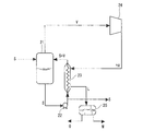
- the reformed coal production apparatus 1 in FIG. 1 mainly includes a tank 2, a heater 3, a compressor 4, a gas / liquid separator 5, a strainer 6, a flocculated liquid receiver 7, and an oil / water separator 8.
- Tank 2 stores slurry S containing coal and oil containing moisture.
- the bottom of the tank 2 communicates with the first pump 9 through a pipe, and the first pump 9 communicates with the pipe inner bottom (inlet) of the heater 3 through the pipe.
- the heater 3 heats the slurry S flowing through a pipe provided therein by heat exchange, and a known heat exchanger can be used.
- the pipe inner top (exit) of the heater 3 and the upper side of the tank 2 communicate with each other by piping. Further, the upper part (inlet) of the heater 3 on the outside of the pipe communicates with the compressor 4 by piping, and the lower part of the pipe on the outside (outlet) communicates with the condensed liquid receiver 7 by piping.
- the coal in the slurry S is dehydrated by heating with the heater 3.
- Compressor 4 compresses steam V to obtain high-temperature steam HV.
- a known compressor can be used for the compressor 4.
- the outlet of the compressor 4 communicates with the upper part of the outside of the tube of the heater 3.
- the gas-liquid separator 5 has a steam inlet 10 on the side wall, a steam outlet 11 on the top, and a liquid outlet 12 on the bottom.
- the vapor inlet 10 of the gas-liquid separator 5 communicates with the top of the tank 2 through a pipe.
- the vapor outlet 11 of the gas-liquid separator 5 communicates with the compressor 4 through a strainer 6 by piping.
- the liquid discharge port 12 of the gas-liquid separator 5 communicates with the aggregate liquid receiver 7 through a pipe.
- a first mist separator 13, a spray 14, and a second mist separator 15 are provided in order from the lower side (upstream side in the flow of the steam V) at a position higher than the steam inlet 10. It has been. That is, the vapor
- the first mist separator 13 is provided in the uppermost stream, that is, the position where the steam V first passes (the position where the steam V first contacts).
- the first mist separator 13 is a vane type mist separator.
- the vane-type mist separator includes a plurality of baffle plates arranged in parallel, and the splashes accompanying the vapor V can be captured when the splashes collide with the baffle plates.
- As the shape of the baffle plate a wavy shape can be suitably used.
- the direction of the ridge of the wavy baffle may be parallel or perpendicular to the steam flow.
- This vane type mist separator can satisfactorily capture, for example, droplets (fine particles) having a particle size of 10 ⁇ m or more.
- the spray 14 has a plurality of spray nozzles.
- the spray 14 is provided so that a liquid can be sprayed onto the first mist separator 13 from above.
- the second mist separator 15 is a mesh mist separator.
- the mesh-type mist separator can capture droplets (fine particles) having a desired particle diameter by adjusting the size of the mesh. For example, it is preferable to use a particle that can capture droplets (fine particles) having a particle size of 1 ⁇ m or more and less than 10 ⁇ m.
- the strainer 6 is provided in a pipe that connects the gas-liquid separator 5 and the compressor 4. This strainer 6 is for removing the solid matter accompanying the steam V.
- the strainer 6 a known one such as one having a structure made of a metal mesh can be used.
- the bottom of the coagulated liquid receiver 7 communicates with the oil / water separator 8 through a filter 16 by piping.
- the oil / water separator 8 includes an oil tank and a water tank for storing the separated oil and water.
- the oil tank is in communication with the spray 14 via a second pump 17 by piping.
- the water tank is drained through a third pump 18 by piping.
- the method for producing the modified coal of the present invention comprises: (A) dehydrating the coal by heating a mixture containing moisture-containing coal and oil; (B) a step of removing the splash entrained by the steam generated by the dehydration; and (C) a step of compressing the steam from which the splash is removed to obtain a high-temperature steam, (D) The process of removing the solid substance accompanying the vapor
- the said manufacturing method is demonstrated below as an example using the said modified coal manufacturing apparatus 1 concretely.
- a slurry S (mixture) containing coal and oil containing moisture is preheated and then supplied to the tank 2.
- the coal is a low-grade coal having a high water content and a relatively small calorific value per unit mass.
- As said coal (low rank coal) subbituminous coal, lignite, lignite, peat, etc. can be used. These coals are pulverized and mixed with oil to form a slurry S.
- the oil a mixed oil containing a heavy oil such as asphalt and a solvent oil such as kerosene can be used.
- the slurry refers to a suspension in which a fine solid is dispersed in a liquid, and is a mixture having fluidity that can generally be pumped.
- the mixture of coal and oil in the present invention is not limited to a slurry, and may be a cake-like mixture having a low fluidity or, on the contrary, a state having an extremely high fluidity.
- Step (A) The slurry S is extracted from the bottom of the tank 2 and supplied to the heater 3 by the first pump 9.
- the slurry S is heated in the heater 3 by heat exchange with the high-temperature steam HV supplied from the compressor 4.
- HV high-temperature steam supplied from the compressor 4.
- the heating temperature is, for example, 100 to 250 ° C., preferably 120 to 200 ° C.
- the slurry S may be in a pressurized state.
- the heated slurry S and the mixed steam V of water and oil are returned to the tank 2.
- the steam V is extracted from the top of the tank 2 and supplied to the gas-liquid separator 5 from the steam inlet 10.
- the steam V is accompanied by splashes, and the splashes contain fine particles such as coal particles.
- the vapor V first passes through the first mist separator 13 (vane type mist separator).
- the first mist separator 13 captures droplets (fine particles) having a relatively large particle size.
- the first mist separator 13 is always sprayed with a liquid (specifically, an oil component O described later) by a spray 14 during operation. By doing in this way, the splash (fine particle) adhering to the surface of the 1st mist separator 13 is washed away with this liquid. Therefore, in the said manufacturing method, since the splash (fine particle) removal ability of a mist separator is high and the frequency of washing
- pressure loss can be suppressed by using a vane type mist separator for the first mist separator 13. Further, when the vane type mist separator has a structure composed of a plurality of corrugated plates, the removal of fine particles using a liquid can be performed particularly easily.
- the temperature of the sprayed liquid is preferably 50 ° C. or higher and 150 ° C. or lower.
- the temperature of the liquid can be adjusted by heating by a known method.
- the liquid to be sprayed it is preferable to use a recycled oil component O described later.
- a recycled oil component O By spraying the oil component O in this way, the ability to remove fine particles fixed to the first mist separator 13 together with the oil can be enhanced.
- the amount of liquid to be sprayed is not particularly limited, but is, for example, about 400 kg / h to 3,500 kg / h, and preferably 1,000 kg / h to 3,000 kg / h.
- the said manufacturing method by spraying a liquid with the spray 14, the liquid itself in this scattering can capture
- the fine particles and liquid washed away are collected at the bottom of the gas-liquid separator 5 and discharged to the agglomerated liquid receiver 7.
- the steam V passes through the first mist separator 13 and the spray 14, and then passes through the second mist separator 15 (mesh type mist separator) provided downstream (upward) thereof.
- the manufacturing method by using two mist separators in this way, the droplets (fine particles) having a relatively large particle size are first removed with a vane-type mist separator with a small pressure loss, and then smaller. Since droplets (fine particles) having a particle size can be removed with a mesh-type mist separator, pressure loss is suppressed and the method is efficient.
- Step (D) The steam V is discharged from the steam outlet 11 of the gas-liquid separator 5 and passes through the strainer 6.
- fine particles captured between the meshes may be dried, and the dried fine particles (solid matter) may be peeled off and mixed into the compressor 4 in some cases.
- the strainer 6 step for removing solids
- Step (E) After the solid content is removed by the filter 16, the aggregate liquid L from the heater 3 and the liquid from the gas-liquid separator 5 stored in the aggregate liquid receiver 7 are transferred to the oil / water separator 8. Supplied. In the oil / water separator 8, the agglomerated liquid and the like are separated into oil O and water W.
- the separated water W is drained through the third pump 18.
- the separated oil component O is supplied to the spray 14 via the second pump 17 as described above and used as a liquid to be sprayed.
- a part of the slurry S is supplied from the first pump 9 to a subsequent process (such as a solid-liquid separation process) to become reformed coal.
- a subsequent process such as a solid-liquid separation process
- the droplets (fine particles) accompanying the steam V generated during the dehydration of coal can be efficiently removed, and the operability is excellent.
- the energy and raw material in a manufacturing process can be used effectively, and productivity is improved. Can be increased.
- the modified coal production method and modified coal production apparatus of the present invention are not limited to the above-described embodiment.
- a plurality of mist separators may not be installed, and a mist separator other than a combination of a vane type mist separator and a mesh type mist separator may be used.
- three or three or more mist separators can be used in combination. Examples of other types of mist separators include a swivel mist separator. These may be appropriately designed in consideration of the ability to remove splashes (fine particles), the degree of allowable pressure loss, and the like.
- liquid to be sprayed oil other than oil separated and reused can be used.
- the aggregated liquid may be used as it is without being separated, or another liquid may be used.
- this steam purification method is: A method for purifying steam comprising a step of removing the splash from the steam accompanying the splash, In the above step, the vapor is sequentially passed through one or a plurality of mist separators, and the droplets are removed while spraying the liquid on the first mist separator through which the vapor first passes.
- the step (B) of removing the spatter in the method for producing modified coal described above can be used in other fields where it is necessary to remove the spatter from the vapor accompanied by the spatter containing fine particles.
- Other fields include distillation and fractionation in petrochemistry and petroleum refining, removal of air pollutants, washing, and the like. Note that details of this step are the same as the above-described step (B), and thus detailed description thereof is omitted.
- the steam cleaning method is excellent in operability because the mist separator has a high ability to remove splashes and the frequency of cleaning can be reduced.
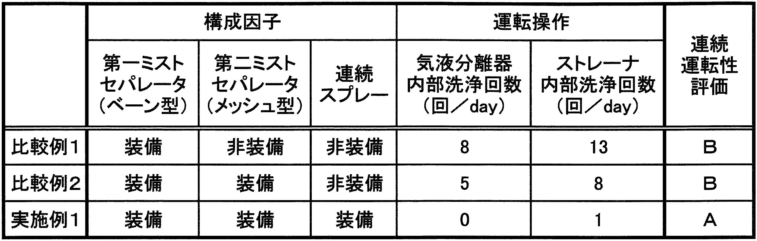
- Example 1 Using the apparatus shown in FIG. 1, the spray in the gas-liquid separator was constantly operated to produce modified coal.
- the amount of steam generated in the heater and supplied to the gas-liquid separator is 12,600 kg / h (water 7,800 kg / h and oil 4,800 kg / h), the pressure is 0.40 MPa, and the temperature is 150 ° C. there were.
- the flow rate of the liquid sprayed from the spray was 2,400 kg / h, and the temperature was 60 ° C.
Landscapes
- Chemical & Material Sciences (AREA)
- Engineering & Computer Science (AREA)
- Oil, Petroleum & Natural Gas (AREA)
- Organic Chemistry (AREA)
- Environmental & Geological Engineering (AREA)
- Geology (AREA)
- Geochemistry & Mineralogy (AREA)
- General Life Sciences & Earth Sciences (AREA)
- Life Sciences & Earth Sciences (AREA)
- Thermal Sciences (AREA)
- Physics & Mathematics (AREA)
- Combustion & Propulsion (AREA)
- Chemical Kinetics & Catalysis (AREA)
- General Engineering & Computer Science (AREA)
- Mechanical Engineering (AREA)
- Food Science & Technology (AREA)
- Solid Fuels And Fuel-Associated Substances (AREA)
Abstract
Description
(A)水分を含有する石炭と油とを含む混合物の加熱により上記石炭を脱水する工程、
(B)上記脱水により生じる蒸気に同伴される飛沫物を除去する工程、及び
(C)上記飛沫物を除去した蒸気を圧縮し、高温蒸気を得る工程
を有する改質石炭の製造方法であって、
上記(B)工程において、上記蒸気を1又は複数のミストセパレータに順次通過させ、最初に蒸気が通過する第一ミストセパレータに液体を噴霧しながら上記飛沫物の除去を行うことを特徴とする。
上記第一ミストセパレータがベーン型であり、
上記第一ミストセパレータの次に蒸気が通過する第二ミストセパレータがメッシュ型であることが好ましい。
このように2つのミストセパレータを用いることで、比較的粒径の大きい飛沫物を先ずベーン型のミストセパレータで除去し、次いで、より小さい粒径の飛沫物をメッシュ型のミストセパレータで除去することができ、効率的である。また、第一ミストセパレータにベーン型ミストセパレータを用いることで、圧力損失を抑えることができ、また、液体の噴霧による微細粒子の除去も容易に行うことができる。
(D)上記飛沫物を除去した蒸気に同伴される固形物を除去する工程
を有することが好ましい。
例えば、上記メッシュ型のミストセパレータを用いた場合、メッシュ間に捕捉された微細粒子が乾燥し固形物となり、この固形物が剥がれて圧縮機に混入する場合がある。そこで、このように固形物を除去する工程を設けることで、圧縮機の性能低下等をより低減させることができる。
この加熱に用いられた高温蒸気の凝集液の少なくとも一部を(B)工程における上記液体として用いることが好ましい。
このようにすることで、製造工程におけるエネルギー及び原料を有効活用することができ、生産性を高めることができる。
を有し、
この(E)工程で得られた油分を(B)工程における上記液体として用いるとよい。
このように油分を第一ミストセパレータに噴霧することで、油分と共に付着した微細粒子をより容易に洗い落とすことができる。
水分を含有する石炭と油とを含むスラリーを貯留するタンク、
上記タンクから供給されるスラリーを高温蒸気との熱交換により加熱し、上記石炭を脱水する加熱器、
上記加熱によりスラリーから生じる蒸気に同伴される飛沫物を除去する気液分離器、及び
上記蒸気を圧縮する圧縮機
を備え、
上記気液分離器が、上記蒸気が順次通過するように配置される1又は複数のミストセパレータと、最初に蒸気が通過する第一ミストセパレータに液体を噴霧するスプレーとを有する。
上記第一ミストセパレータがベーン型であり、
上記第一ミストセパレータの次に蒸気が通過する第二ミストセパレータがメッシュ型であるとよい。
当該改質石炭製造装置が、このような二種のミストセパレータを組み合わせて有することで、圧力損失を抑えつつ、微細粒子の除去能等を高めることができる。
図1の改質石炭製造装置1は、タンク2、加熱器3、圧縮機4、気液分離器5、ストレーナ6、凝集液受け器7及び油水分離器8を主に備える。
本発明の改質石炭の製造方法は、
(A)水分を含有する石炭と油とを含む混合物の加熱により上記石炭を脱水する工程、
(B)上記脱水により生じる蒸気に同伴される飛沫物を除去する工程、及び
(C)上記飛沫物を除去した蒸気を圧縮し、高温蒸気を得る工程
を有し、好適には、
(D)上記(B)工程と(C)工程との間に、上記飛沫物を除去した蒸気に同伴される固形物を除去する工程、及び
(E)上記凝集液を油水分離する工程
をさらに有する。
当該製造方法について、具体的に上記改質石炭製造装置1を用いた例として以下に説明する。
スラリーSは、タンク2の底部から抜き出され、第一ポンプ9により加熱器3に供給される。スラリーSは、加熱器3において、圧縮機4から供給される高温蒸気HVとの熱交換により加熱さる。この加熱により、石炭(低品位炭)が脱水され、具体的にはこの石炭の細孔内に存在する水分及び混合油の一部が蒸発する。この加熱温度としては、例えば100~250℃であり、120~200℃が好ましい。なお、この加熱の際、スラリーSは加圧状態であってもよい。
上記蒸気Vには、上述したように飛沫物が同伴され、この飛沫物には石炭の粒子等の微細粒子が含まれる。気液分離器5においては、蒸気Vが最初に第一ミストセパレータ13(ベーン型ミストセパレータ)を通過する。この第一ミストセパレータ13により、比較的粒径の大きい飛沫物(微細粒子)が捕捉される。第一ミストセパレータ13には、スプレー14により液体(具体的には後述する油分O)が、稼働中常時噴霧されている。このようにすることで、第一ミストセパレータ13の表面に付着する飛沫物(微細粒子)は、この液体により洗い流される。従って、当該製造方法においては、ミストセパレータの飛沫物(微細粒子)除去能が高く、また、第一ミストセパレータ13等の洗浄の頻度も少なくすることができるため、操業性にも優れる。
蒸気Vは、気液分離器5の蒸気流出口11から排出され、ストレーナ6を通過する。上記メッシュ型のミストセパレータを用いた場合、メッシュ間に捕捉された微細粒子が乾燥し、この乾燥した微細粒子(固形物)が剥がれて圧縮機4に混入する場合がある。そこで、このようにストレーナ6(固形物を除去する工程)を設けることで、圧縮機4の性能低下等をより低減させることができる。
上記ストレーナ6を通過し、飛沫物等が除去された蒸気Vは、圧縮機4にて圧縮され高温蒸気HVとなる。この高温蒸気HVは、加熱器3における熱媒として利用される。また、熱交換によりこの高温蒸気HVは凝集して凝集液Lとなり、この凝集液Lは凝集液受け器7に貯留される。
上記凝集液受け器7に貯留される加熱器3からの凝集液L及び気液分離器5からの液体等は、フィルター16により固形分が除去された後、油水分離器8に供給される。この油水分離器8においては、上記凝集液等が油分Oと水分Wとに分離される。
本発明の改質石炭の製造方法及び改質石炭製造装置は、上記実施形態に限定されるものではない。例えば、当該改質石炭製造装置においては、複数のミストセパレータを設置しなくともよく、また、ベーン型ミストセパレータとメッシュ型ミストセパレータとの組合せ以外のミストセパレータを用いてもよい。また、3台又は3種以上のミストセパレータを組み合わせて用いることもできる。他のタイプのミストセパレータとしては、例えば旋回式のミストセパレータ等を例示することができる。これらは、飛沫物(微細粒子)除去能や許容できる圧力損失の程度等を考慮して適宜設計すればよい。
本発明の改質石炭の製造方法の一部は、蒸気の浄化方法として他の分野に応用することもできる。すなわち、この蒸気の浄化方法は、
飛沫物を同伴する蒸気からこの飛沫物を除去する工程
を有する蒸気の浄化方法であって、
上記工程において、上記蒸気を1又は複数のミストセパレータに順次通過させ、最初に蒸気が通過する第一ミストセパレータに液体を噴霧しながら上記飛沫物の除去を行うことを特徴とする。
図1に示す装置を用い、常時気液分離器中のスプレーを稼働させて改質石炭を製造した。加熱器で発生し、気液分離器に供給される蒸気の量は12,600kg/h(水7,800kg/h及び油4,800kg/h)、圧力は0.40MPa、温度は150℃であった。これに対して、スプレーから噴霧する液体(リサイクルした油)の流量は2,400kg/h、温度は60℃とした。
図3に示す装置において、圧縮機の前にストレーナを設置したものを用いて改質石炭を製造した。加熱器で発生する蒸気の量、圧力及び温度は実施例1と同様である。
スプレーを稼働させなかったこと以外は、実施例1と同様にして改質石炭を製造した。
実施例及び比較例において、気液分離器の内部洗浄回数及びストレーナの内部洗浄回数から、連続運転性(操業性)を評価した。なお、それぞれ3日ずつ操業し、その平均回数とした。また、各内部洗浄は、目視等から気液分離器及びストレーナの捕捉能が実質的に機能しない程度に低下したと判断した時点で行った。この連続運転性は、気液分離器及びストレーナの内部洗浄回数がともに3回/day未満の場合をA、これらの洗浄回数のうち一方が3回/day以上の場合をBとして評価した。評価結果を表1に示す。
2 タンク
3 加熱器
4 圧縮機
5 気液分離器
6 ストレーナ
7 凝集液受け器
8 油水分離器
9 第一ポンプ
10 蒸気流入口
11 蒸気流出口
12 液排出口
13 第一ミストセパレータ
14 スプレー
15 第二ミストセパレータ
16 フィルター
17 第二ポンプ
18 第三ポンプ
S スラリー
V 蒸気
HV 高温蒸気
L 凝集液
O 油分
W 水分
Claims (10)
- (A)水分を含有する石炭と油とを含む混合物の加熱により上記石炭を脱水する工程、
(B)上記脱水により生じる蒸気に同伴される飛沫物を除去する工程、及び
(C)上記飛沫物を除去した蒸気を圧縮し、高温蒸気を得る工程
を有する改質石炭の製造方法であって、
上記(B)工程において、上記蒸気を1又は複数のミストセパレータに順次通過させ、最初に蒸気が通過する第一ミストセパレータに液体を噴霧しながら上記飛沫物の除去を行うことを特徴とする改質石炭の製造方法。 - 上記(B)工程において、複数のミストセパレータを用い、
上記第一ミストセパレータがベーン型であり、
上記第一ミストセパレータの次に蒸気が通過する第二ミストセパレータがメッシュ型である請求項1に記載の改質石炭の製造方法。 - 上記(B)工程と(C)工程との間に、
(D)上記飛沫物を除去した蒸気に同伴される固形物を除去する工程
を有する請求項1に記載の改質石炭の製造方法。 - 上記(C)工程で得られた高温蒸気を(A)工程の加熱に用い、
この加熱に用いられた高温蒸気の凝集液の少なくとも一部を(B)工程における上記液体として用いる請求項1に記載の改質石炭の製造方法。 - (E)上記凝集液を油水分離する工程
を有し、
この(E)工程で得られた油分を(B)工程における上記液体として用いる請求項4に記載の改質石炭の製造方法。 - 上記(B)工程において噴霧する液体の温度が50℃以上150℃以下である請求項1から請求項5のいずれか1項に記載の改質石炭の製造方法。
- 水分を含有する石炭と油とを含むスラリーを貯留するタンク、
上記タンクから供給されるスラリーを高温蒸気との熱交換により加熱し、上記石炭を脱水する加熱器、
上記加熱によりスラリーから生じる蒸気に同伴される飛沫物を除去する気液分離器、及び
上記蒸気を圧縮する圧縮機
を備え、
上記気液分離器が、上記蒸気が順次通過するように配置される1又は複数のミストセパレータと、最初に蒸気が通過する第一ミストセパレータに液体を噴霧するスプレーとを有する改質石炭製造装置。 - 上記気液分離器が複数のミストセパレータを有し、
上記第一ミストセパレータがベーン型であり、
上記第一ミストセパレータの次に蒸気が通過する第二ミストセパレータがメッシュ型である請求項7に記載の改質石炭製造装置。 - 上記飛沫物を除去した蒸気に同伴される固形物を除去するストレーナ
をさらに備える請求項7に記載の改質石炭製造装置。 - 上記加熱器での加熱により生じる高温蒸気の凝集液を油水分離する油水分離器
をさらに備える請求項7、請求項8又は請求項9に記載の改質石炭製造装置。
Priority Applications (5)
| Application Number | Priority Date | Filing Date | Title |
|---|---|---|---|
| US14/423,897 US10465136B2 (en) | 2012-11-16 | 2013-09-18 | Refined-coal production method, and refined-coal production device |
| AU2013346096A AU2013346096B2 (en) | 2012-11-16 | 2013-09-18 | Refined-coal production method, and refined-coal production device |
| RU2015119970A RU2617690C2 (ru) | 2012-11-16 | 2013-09-18 | Способ получения очищенного угля и устройство для получения очищенного угля |
| EP13854513.2A EP2921548A4 (en) | 2012-11-16 | 2013-09-18 | PROCESS AND DEVICE FOR MANUFACTURING REFORMING CHARCOAL |
| CN201380059529.4A CN104837965B (zh) | 2012-11-16 | 2013-09-18 | 改质煤的制造方法以及改质煤制造装置 |
Applications Claiming Priority (2)
| Application Number | Priority Date | Filing Date | Title |
|---|---|---|---|
| JP2012-252628 | 2012-11-16 | ||
| JP2012252628A JP5805613B2 (ja) | 2012-11-16 | 2012-11-16 | 改質石炭の製造方法及び改質石炭製造装置 |
Publications (1)
| Publication Number | Publication Date |
|---|---|
| WO2014077027A1 true WO2014077027A1 (ja) | 2014-05-22 |
Family
ID=50730950
Family Applications (1)
| Application Number | Title | Priority Date | Filing Date |
|---|---|---|---|
| PCT/JP2013/075199 Ceased WO2014077027A1 (ja) | 2012-11-16 | 2013-09-18 | 改質石炭の製造方法及び改質石炭製造装置 |
Country Status (7)
| Country | Link |
|---|---|
| US (1) | US10465136B2 (ja) |
| EP (1) | EP2921548A4 (ja) |
| JP (1) | JP5805613B2 (ja) |
| CN (1) | CN104837965B (ja) |
| AU (1) | AU2013346096B2 (ja) |
| RU (1) | RU2617690C2 (ja) |
| WO (1) | WO2014077027A1 (ja) |
Cited By (2)
| Publication number | Priority date | Publication date | Assignee | Title |
|---|---|---|---|---|
| WO2015016211A1 (ja) * | 2013-07-30 | 2015-02-05 | 株式会社神戸製鋼所 | 溶剤分離方法 |
| RU2671204C1 (ru) * | 2014-12-08 | 2018-10-30 | Кабусики Кайся Кобе Сейко Се (Кобе Стил, Лтд.) | Способ получения твердого топлива и установка для получения твердого топлива |
Families Citing this family (4)
| Publication number | Priority date | Publication date | Assignee | Title |
|---|---|---|---|---|
| DE102018002447A1 (de) * | 2018-03-23 | 2019-09-26 | Mann+Hummel Vokesair Gmbh | Mehrstufiger Aerosolabscheider, Vorabscheider-Stufen-Modul, Nachrüst- und Betriebsverfahren dafür |
| US11207627B2 (en) * | 2018-10-17 | 2021-12-28 | University Of Kentucky Research Foundation | Filter assembly and scrubber section for a continuous miner |
| CN113174280A (zh) * | 2021-04-20 | 2021-07-27 | 西安热工研究院有限公司 | 一种锅炉化学清洗废水喷淋煤场系统及方法 |
| CN113281533B (zh) * | 2021-05-19 | 2022-11-01 | 上海交通大学 | 基于沙漏加注和多级过滤的固态示踪粒子布撒装置 |
Citations (5)
| Publication number | Priority date | Publication date | Assignee | Title |
|---|---|---|---|---|
| JPS6012114A (ja) * | 1983-06-30 | 1985-01-22 | Isuzu Seisakusho:Kk | 排ガス浄化処理装置 |
| JPS60125223A (ja) * | 1983-12-10 | 1985-07-04 | Eishin Kucho Kk | 塗装における余剰ミスト捕集装置 |
| JPH07233383A (ja) | 1993-12-27 | 1995-09-05 | Kobe Steel Ltd | 多孔質炭を原料とする固形燃料、その製造方法及び製造装置 |
| JP2003047814A (ja) * | 2001-08-03 | 2003-02-18 | Takasago Thermal Eng Co Ltd | ミストセパレータ及びその運転方法 |
| JP4365442B1 (ja) * | 2008-05-29 | 2009-11-18 | 株式会社神戸製鋼所 | 石炭の改質方法 |
Family Cites Families (10)
| Publication number | Priority date | Publication date | Assignee | Title |
|---|---|---|---|---|
| NL7812248A (nl) * | 1978-12-18 | 1980-06-20 | Shell Int Research | Thermische behandeling van kool. |
| US5083975A (en) * | 1990-11-28 | 1992-01-28 | Oscar Mayer Foods Corp | Method for reducing fecal leakage and contamination during meat and poultry processing |
| AU668328B2 (en) | 1993-12-27 | 1996-04-26 | Kabushiki Kaisha Kobe Seiko Sho (Kobe Steel Ltd) | Solid fuel made from porous coal and production process and production apparatus therefore |
| DE19505231A1 (de) * | 1995-02-16 | 1996-08-22 | Metallgesellschaft Ag | Verfahren zum Reinigen von Gasen mit Wasser |
| US7905937B2 (en) | 2007-09-13 | 2011-03-15 | Koch-Glitch, LP | Two-stage mist eliminator and method |
| MY155517A (en) * | 2008-03-31 | 2015-10-30 | C&C Res Lab | Heterocyclic derivatives |
| US8603301B2 (en) * | 2009-10-05 | 2013-12-10 | General Electric Company | Method for reduction of contaminants in evaporator distillate |
| CN101705131B (zh) * | 2009-11-19 | 2012-09-05 | 李功民 | 一种干燥干选联合原煤提质设备及方法 |
| US8236142B2 (en) * | 2010-05-19 | 2012-08-07 | Westbrook Thermal Technology, Llc | Process for transporting and quenching coke |
| CN103071371B (zh) * | 2011-10-26 | 2014-12-31 | 密西西比国际水务(中国)有限公司 | 一种活性焦再生混合汽的处理方法和装置 |
-
2012
- 2012-11-16 JP JP2012252628A patent/JP5805613B2/ja active Active
-
2013
- 2013-09-18 WO PCT/JP2013/075199 patent/WO2014077027A1/ja not_active Ceased
- 2013-09-18 US US14/423,897 patent/US10465136B2/en not_active Expired - Fee Related
- 2013-09-18 AU AU2013346096A patent/AU2013346096B2/en active Active
- 2013-09-18 RU RU2015119970A patent/RU2617690C2/ru active
- 2013-09-18 EP EP13854513.2A patent/EP2921548A4/en not_active Withdrawn
- 2013-09-18 CN CN201380059529.4A patent/CN104837965B/zh active Active
Patent Citations (6)
| Publication number | Priority date | Publication date | Assignee | Title |
|---|---|---|---|---|
| JPS6012114A (ja) * | 1983-06-30 | 1985-01-22 | Isuzu Seisakusho:Kk | 排ガス浄化処理装置 |
| JPS60125223A (ja) * | 1983-12-10 | 1985-07-04 | Eishin Kucho Kk | 塗装における余剰ミスト捕集装置 |
| JPH07233383A (ja) | 1993-12-27 | 1995-09-05 | Kobe Steel Ltd | 多孔質炭を原料とする固形燃料、その製造方法及び製造装置 |
| JP2003047814A (ja) * | 2001-08-03 | 2003-02-18 | Takasago Thermal Eng Co Ltd | ミストセパレータ及びその運転方法 |
| JP4365442B1 (ja) * | 2008-05-29 | 2009-11-18 | 株式会社神戸製鋼所 | 石炭の改質方法 |
| JP2009286900A (ja) | 2008-05-29 | 2009-12-10 | Kobe Steel Ltd | 石炭の改質方法 |
Non-Patent Citations (1)
| Title |
|---|
| See also references of EP2921548A4 |
Cited By (3)
| Publication number | Priority date | Publication date | Assignee | Title |
|---|---|---|---|---|
| WO2015016211A1 (ja) * | 2013-07-30 | 2015-02-05 | 株式会社神戸製鋼所 | 溶剤分離方法 |
| JP2015028102A (ja) * | 2013-07-30 | 2015-02-12 | 株式会社神戸製鋼所 | 溶剤分離方法 |
| RU2671204C1 (ru) * | 2014-12-08 | 2018-10-30 | Кабусики Кайся Кобе Сейко Се (Кобе Стил, Лтд.) | Способ получения твердого топлива и установка для получения твердого топлива |
Also Published As
| Publication number | Publication date |
|---|---|
| JP5805613B2 (ja) | 2015-11-04 |
| US10465136B2 (en) | 2019-11-05 |
| US20150210946A1 (en) | 2015-07-30 |
| CN104837965A (zh) | 2015-08-12 |
| CN104837965B (zh) | 2017-11-10 |
| AU2013346096A1 (en) | 2015-05-14 |
| EP2921548A1 (en) | 2015-09-23 |
| EP2921548A4 (en) | 2016-05-04 |
| RU2617690C2 (ru) | 2017-04-26 |
| RU2015119970A (ru) | 2017-01-10 |
| AU2013346096B2 (en) | 2016-05-12 |
| JP2014101413A (ja) | 2014-06-05 |
Similar Documents
| Publication | Publication Date | Title |
|---|---|---|
| JP5805613B2 (ja) | 改質石炭の製造方法及び改質石炭製造装置 | |
| CN102027099B (zh) | 煤炭的改质方法以及改质装置 | |
| CN102225794A (zh) | 一种组合式餐厨垃圾废水油水分离装置及方法 | |
| RU2381822C1 (ru) | Установка подготовки углеводородного газа | |
| EA006143B1 (ru) | Способ разделения и устройство для удаления материала в форме частиц из газойля коксовой печи с задержкой | |
| CN105233602B (zh) | 用于粉煤低温干馏中高温焦油气与细粉尘颗粒分离的系统 | |
| CN101792224A (zh) | 延迟焦化放空水处理的方法与装置 | |
| CN115676781B (zh) | 一种硫泡沫的处理系统和方法 | |
| CN204311035U (zh) | 适于含油污泥热解吸气气体净化处理的装置 | |
| CN108219882A (zh) | 析硫井口防硫堵系统 | |
| CN207628144U (zh) | 含固烃类气体冷却净化装置 | |
| US9670431B2 (en) | Indirect heat drying method for particulate matter, refined-coal production method, indirect heat drying device, and refined-coal production device | |
| CN108993120B (zh) | 一种脱硫废水协同除尘除雾装置及除尘除雾工艺 | |
| CN102424444B (zh) | 一种原油电脱盐装置脱盐水除油的方法及其装置 | |
| RU2368643C2 (ru) | Способ очистки масел | |
| CN204815930U (zh) | 一种化工分级过滤装置 | |
| CN114850169A (zh) | 一种降低焦油渣中水分含量的方法 | |
| CN102432114B (zh) | 油母页岩干馏系统集合管段油泥多级浓缩方法及装置 | |
| CN101353207A (zh) | 酸性水除油除焦方法及装置 | |
| Chen et al. | Collaborative removal of fine catalysts particles and insoluble organics from methanol-to-olefins reaction wastewater using horizontal swirl regeneration micro-channel separation (HSRMS) | |
| CN209596581U (zh) | 一种刮板式薄膜蒸发器用吸附净油装置 | |
| CN114275836B (zh) | 一种利用烟气余热处理含盐污水的方法和装置 | |
| CN219252226U (zh) | 一种胺液梯级除油脱固深度净化装置 | |
| CN108165319A (zh) | 一种高效焦油回收装置 | |
| CN203829786U (zh) | 一种真空滤油机 |
Legal Events
| Date | Code | Title | Description |
|---|---|---|---|
| 121 | Ep: the epo has been informed by wipo that ep was designated in this application |
Ref document number: 13854513 Country of ref document: EP Kind code of ref document: A1 |
|
| WWE | Wipo information: entry into national phase |
Ref document number: 14423897 Country of ref document: US |
|
| REEP | Request for entry into the european phase |
Ref document number: 2013854513 Country of ref document: EP |
|
| WWE | Wipo information: entry into national phase |
Ref document number: 2013854513 Country of ref document: EP |
|
| ENP | Entry into the national phase |
Ref document number: 2013346096 Country of ref document: AU Date of ref document: 20130918 Kind code of ref document: A |
|
| NENP | Non-entry into the national phase |
Ref country code: DE |
|
| ENP | Entry into the national phase |
Ref document number: 2015119970 Country of ref document: RU Kind code of ref document: A |