WO2014077337A1 - 落雷の電荷量推定システムと方法 - Google Patents
落雷の電荷量推定システムと方法 Download PDFInfo
- Publication number
- WO2014077337A1 WO2014077337A1 PCT/JP2013/080836 JP2013080836W WO2014077337A1 WO 2014077337 A1 WO2014077337 A1 WO 2014077337A1 JP 2013080836 W JP2013080836 W JP 2013080836W WO 2014077337 A1 WO2014077337 A1 WO 2014077337A1
- Authority
- WO
- WIPO (PCT)
- Prior art keywords
- magnetic field
- lightning strike
- lightning
- current
- charge amount
- Prior art date
- Legal status (The legal status is an assumption and is not a legal conclusion. Google has not performed a legal analysis and makes no representation as to the accuracy of the status listed.)
- Ceased
Links
Images





Classifications
-
- G—PHYSICS
- G01—MEASURING; TESTING
- G01W—METEOROLOGY
- G01W1/00—Meteorology
- G01W1/16—Measuring atmospheric potential differences, e.g. due to electrical charges in clouds
-
- G—PHYSICS
- G01—MEASURING; TESTING
- G01R—MEASURING ELECTRIC VARIABLES; MEASURING MAGNETIC VARIABLES
- G01R33/00—Arrangements or instruments for measuring magnetic variables
- G01R33/02—Measuring direction or magnitude of magnetic fields or magnetic flux
Definitions
- the present invention relates to a charge amount estimation system and method for estimating the charge amount of a lightning strike.
- Patent Document 1 discloses a lightning strike location system that measures characteristic radio waves generated by lightning strikes at a plurality of points and estimates the position of lightning strikes based on differences in reception time and arrival directions of radio waves.
- This lightning location system is based on the relationship between the peak value of the large feedback current that flows immediately after the discharge descends from the thundercloud and reaches the ground, and is proportional to the peak value of the radio wave intensity and the distance from the lightning strike. Estimate the peak value of.
- a technology for estimating the amount of lightning strike a technology for estimating the amount of charge from the voltage generated in the shunt resistor by the current flowing through the shunt resistor inserted between the lighted structure and the ground
- a technique is known in which a magnetic field generated by a current flowing through an object is measured by a Rogowski coil, and the charge amount is estimated from the measured magnetic field.
- the amount of charge can be estimated only when lightning strikes the observation facility and measurement data is obtained.
- the measurement information obtained is limited to data on a specific type of lightning, such as lightning on a high structure where lightning frequently occurs. In reality, it is difficult to predict when and where lightning strikes will occur. For this reason, the conventional technology for estimating the amount of charge caused by lightning strikes cannot determine the amount of lightning strikes on various structures in a wide area.
- the present invention has been made in view of the above circumstances, and an object thereof is to provide a lightning strike amount estimation system and method capable of easily estimating the amount of lightning strike to various objects in a wide area. To do.
- the lightning strike charge amount estimation system includes a magnetic field measurement unit that measures a magnetic field generated by a lightning strike in a frequency band including a frequency of 200 Hz or less, and the lightning strike based on the magnetic field measured by the magnetic field measurement unit.
- Charge amount calculating means for determining the amount of charge and calculating the amount of charge by integrating the current.
- the lightning charge estimation system of the present invention uses the fact that a magnetic field generated by a lightning strike is measured in a low frequency band of 200 Hz or less and is similar to the current caused by the lightning strike. Ask. Moreover, the lightning strike charge amount estimation system integrates the current to obtain the charge amount that has flowed to the ground due to the lightning strike, thereby estimating the lightning strike charge amount. By combining the estimated lightning strike amount with lightning location information obtained by the Lightning Location System (LLS), etc., potential damage due to lightning strikes such as transmission line melting can be estimated. It is possible to provide materials for determining the necessity of damage countermeasures.
- LLS Lightning Location System
- the lightning strike charge amount estimation system can remotely observe even lightning strikes occurring up to several hundred kilometers away by measuring a magnetic field in a low frequency band including a frequency of 200 Hz or less. . For this reason, one observation device can cover a wide area, and the observation efficiency is high. In addition, the number of observation devices can be reduced, and the installation cost of new observation devices can be reduced.
- the frequency band preferably includes a frequency of 100 Hz or less in a wide band.
- the measured magnetic field waveform and the current waveform are better matched, and the charge amount estimation accuracy can be improved.
- the lightning strike charge amount estimation system may include filter means for applying a filter having a cutoff frequency of 100 Hz on the high frequency side to the magnetic field measured by the magnetic field measurement means.
- the charge amount calculating means may obtain the charge amount based on the magnetic field after being filtered by the filter means. In this case, the magnetic field after applying the filter and the current more closely match, and the charge amount estimation accuracy can be improved.
- the magnetic field measuring means may be capable of measuring two orthogonal components of a magnetic field generated by a lightning strike.
- the lightning strike charge amount estimation system may include azimuth estimation means for obtaining the direction of the lightning strike based on each component of the magnetic field measured by the magnetic field measurement means.
- the measurement accuracy of the lightning strike position can be enhanced by combining with a lightning strike location system.
- the magnetic field measuring means includes a low frequency region in a frequency band to be measured so that the measured magnetic field does not include a value having a polarity opposite to the initial polarity. Also good.
- the charge amount calculation means may determine the charge amount after correcting the magnetic field or the current obtained based on the magnetic field so as not to include a value having a polarity opposite to the initial polarity. In this case, the estimation accuracy of the charge amount can be increased.
- the charge amount calculating means is, for example, means for obtaining a lightning strike current by multiplying a measured magnetic field by a preset magnetic field current conversion coefficient, and based on the obtained current based on the length and slope of the discharge path. Means for multiplying the correction coefficient, and integration means for integrating the current multiplied by the correction coefficient.
- the magnetic field current conversion coefficient is set in consideration of at least one of the attenuation of the magnetic field depending on the distance from the lightning strike point to the magnetic field measurement point and the attenuation of the magnetic field depending on the state of the ionosphere, for example.
- the lightning strike charge estimation method includes: Measuring a magnetic field generated by a lightning strike; Determining a lightning strike current based on the measured magnetic field; Integrating the obtained current to determine the amount of charge due to lightning, Have
- the program of the present invention On the computer, Determining a lightning strike current based on the measured magnetic field; Integrating the obtained current to determine the amount of charge due to lightning, Is executed.
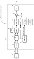
- FIG. 1 is a block diagram of a lightning strike charge amount estimation system according to an embodiment of the present invention.
- FIG. It is a figure which shows the specific structural example of the electric charge amount calculation part shown in FIG. It is a figure which shows the structural example of the data memorize
- FIG. 8 is a graph showing a current waveform after applying a filter (attenuation rate: ⁇ 6 dB / octave) having a cutoff frequency of 90 Hz on the high frequency side to the current waveform shown in FIG. 7.
- FIG. 11 Schematic diagram of a cylindrical coordinate system FDTD simulation for reproducing the propagation of an electromagnetic pulse of 296 km from a lightning generated at Ogamidake to Onagawa Observatory, under the ionosphere, with respect to a lightning charge estimation system according to an embodiment of the present invention. It is. It is a graph which shows the horizontal magnetic field waveform in the distance of 298 km from the lightning obtained by the simulation shown in FIG. 11 is a graph showing a horizontal magnetic field waveform with a propagation distance of 298 km when the lightning current is assumed to be a Gaussian pulse with a half width of 4 ms, obtained by the simulation shown in FIG.
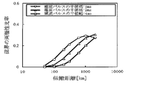
- FIG. 13 is a graph showing the relationship between the logarithmic peak value of the horizontal magnetic field pulse and the logarithmic propagation distance obtained by the simulation shown in FIG. 4 under the same conditions as FIG. It is a graph which shows the propagation distance dependence of the bipolar ratio of a magnetic field pulse when changing the half width of a current pulse obtained by the simulation shown in FIG.
- the lightning strike charge amount estimation system 100 includes a magnetic field measurement unit 10 and a charge amount calculation unit 20.
- the magnetic field measuring unit 10 includes a search coil magnetic field meter having directivity in the north-south direction and the east-west direction.
- the magnetic field measurement unit 10 measures two horizontal components Hns and Hew in the geographical north-south (latitude) direction and east-west direction of the magnetic field generated by lightning strikes in a low frequency band of 200 Hz or less.
- the measurement range of the magnetic field measurement unit 10 preferably includes a low frequency region such that the measurement range is 0.1 Hz or more so that the measured magnetic field does not include a negative polarity component.
- the measurement range may be up to 100 Hz. However, it is desirable to have sufficient sensitivity even in the vicinity of 100 Hz.
- the magnetic field measurement unit 10 supplies the measured magnetic field component Hns in the north-south direction and the magnetic field component Hew in the east-west direction to the charge amount calculation unit 20.
- the charge amount calculation unit 20 includes a computer device, and functionally includes an A / D converter 21, a low-pass filter (LPF) 22, an RTC 23, a storage unit 24, a distance determination unit 25, an ionosphere information collection unit 26, a magnetic field.
- a current ratio table 27, a current calculation unit 28, a multiplication unit 29, and an integration unit 30 are provided.
- the A / D converter 21 converts the north-south magnetic field component Hns and the east-west magnetic field component Hew measured by the magnetic field measuring unit 10 into digital data.
- the sampling period ⁇ t of the A / D converter 21 is, for example, 5 ms to 10 ⁇ s, preferably about 100 ⁇ s.
- the low-pass filter 22 is composed of a digital filter, and extracts and outputs a low-frequency component with a cutoff frequency of about 100 Hz. This increases the similarity between the actually measured magnetic field waveform and the actual magnetic field waveform.
- the RTC (Real Time Clock) 23 measures the current date and time.
- the configuration of the RTC 23 is arbitrary.
- the RTC 23 may be composed of a self-running timer or a GPS (Global Positioning System) timer.
- the storage unit 24 stores the magnetic field components Hns and Hew that have passed through the low-pass filter 22 in association with the current time measured by the RTC 23.
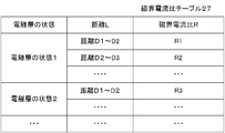
- the distance discriminating unit 25 identifies the lightning strike point based on the magnetic field components Hns and Hew that have passed through the low-pass filter 22, information from a lightning strike location system installed at another point, and the distance from the installation point of the magnetic field measurement unit 10. Ask for. More specifically, as illustrated in FIG.
- the ionosphere information collection unit 26 collects ionosphere information indicating the ionosphere state via the network.
- the ionosphere information may include information such as day and night.
- the multiplication unit 29 multiplies the value obtained by the current calculation unit 28 by the correction coefficient K to obtain the current value obtained by the current calculation unit 28 as the current value when the lightning discharge path is perpendicular to the ground.
- the actual length of the discharge path is obtained by statistical processing, simulation, or the like based on the area where lightning strikes occur, weather conditions, etc., and is set in advance.
- DL is the length of the discharge path assumed when the magnetic field current ratio R stored in the magnetic field current ratio table 27 is obtained.
- ⁇ is the inclination angle of the lightning discharge path.
- ⁇ is obtained by statistical processing, simulation, or the like based on the lightning strike area, weather conditions, and the like.
- the coefficient K may be expressed in the form of a table or function with the region and weather conditions as parameters.
- the integrating unit 30 integrates the current from the start point to the end point of the lightning strike by accumulating the calculation result of the multiplication unit 29 (the corrected instantaneous value of the current), and calculates the charge amount Q that has flowed due to the lightning strike. Ask.
- the above-described charge amount calculation unit 20 includes a CPU (Central Processing Unit) 201, a memory 202, an input device 203, a communication device 204, an output device 205, and an A / D converter. 21, RTC 23, and the like.
- CPU Central Processing Unit
- the memory 202 stores magnetic field data observed as the storage unit 24, stores an operation program and the like, and further functions as a work area of the CPU 201.
- the CPU 201 executes an operation program stored in the memory 202 and executes processing of each unit.
- the input device 203 takes in the magnetic field components Hns and Hew output from the A / D converter 21.
- the communication device 204 communicates with an external device via a network, captures that a lightning has occurred, information for specifying a lightning strike point, ionosphere information, and the like.
- the output device 205 outputs the calculated lightning charge Q of the lightning strike.
- the magnetic field measurement unit 10 always measures the magnetic component Hns in the north-south direction and the magnetic field component Hew in the east-west direction, and supplies measurement data to the charge amount calculation unit 20.
- the A / D converter 21 of the charge amount calculation unit 20 samples the magnetic field components Hns and Hew observed by the magnetic field measurement unit 10 at a constant sampling frequency, converts them into digital data, and outputs them. This digital data is accumulated and stored in the memory 202 functioning as the storage unit 24 via the input device 203.
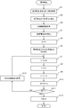
- the CPU 201 monitors the accumulated combined magnetic field. If the value of the combined magnetic field exceeds the threshold value, it is determined that a lightning strike has occurred, and the lightning strike shown in FIG. A process for obtaining the point and the charge amount is executed. Note that the CPU 201 starts the same processing when a lightning strike is notified from the external device via the communication device 204.
- the CPU 201 specifies the start point and the end point of lightning strike from the change of the strength H of the synthetic magnetic field as the current calculation unit 28 (step S1).
- the CPU 201 uses the distance discriminating unit 25 to determine the direction of the lightning strike (Hns / Hes) from the ratio (Hns / Hes) of the north-south magnetic field strength Hns and the east-west magnetic field strength Hew when the strength of the combined magnetic field is equal to or higher than the reference level.
- ⁇ tan ⁇ 1 (Hns / Hew)) is obtained.
- the CPU 201 cooperates with other devices to obtain the lightning strike point P3 by using the triangulation method illustrated in FIG. 4 and the like, and obtains the distance L from the installation place P2 of the magnetic field measurement unit 10 (step S2).
- the CPU 201 accesses the outside via the communication device 204 and collects information indicating ionosphere information (step S3). Next, the CPU 201 obtains a magnetic field current ratio R that matches the state of the ionosphere and the distance L from the magnetic field current ratio table 27 stored in the memory 202 (step S4).
- the charge amount Q is initialized (step S5).
- the CPU 201 sequentially reads the intensity H of the combined magnetic field at the time of lightning strike from the memory 202 (step S5), and obtains the product H ⁇ R with the magnetic field current ratio R (step S7). This indicates the average value I of the current that has flowed by the lightning strike at the start of the lightning strike. Further, as the multiplication unit 29, the CPU 201 multiplies the obtained current value I by the correction coefficient K. As a result, a current value I corrected for variations in the length and inclination of the discharge path is obtained (step S8).
- the CPU 201 multiplies the obtained current value I by the sampling period ⁇ t. Thereby, the charge amount q that has flowed during the sampling period ⁇ t is obtained (step S9).
- the CPU 201 as the integration unit 30, accumulates the output of the multiplication unit 29 and obtains the charge amount Q due to the lightning strike (step S10).
- step S11 determines whether or not the processing has been completed up to the measurement magnetic field H at the end of lightning strike. If not (step S11; No), the CPU 201 determines the intensity H of the combined magnetic field for the next processing target sampling period. Reading (step S12), returning to step S7, the same processing is performed. If it is determined in step S11 that the process has been completed (step S11; Yes), the obtained charge amount Q due to the lightning strike is output (step S13).
- the lightning strike charge amount estimation system 100 can also set the sensitivity of the magnetic field measurement unit 10 to 100 Hz or less. However, it is desirable that the magnetic field measurement unit 10 itself has sensitivity up to about 200 Hz so as not to reduce the accuracy of charge amount estimation.
- the cut-off frequency of the low-pass filter 22 may be set to 200 Hz.
- the low-pass filter 22 may be disposed in front of the A / D converter 21 as an analog filter.
- the lightning strike position specifying function may be removed from the distance determination unit 25, and the lightning strike position information may be received from the outside, for example, from an external lightning strike location system.
- the charge amount calculation unit 20 is configured by a digital circuit (computer) has been shown, it may be configured by an analog circuit.
- the magnetic field measurement data stored in the storage unit 24 may have a polarity opposite to the initial value.
- the measurement data may show positive polarity initially and then negative polarity. This is one of the reasons that the sensitivity on the low frequency side of the magnetic field measuring unit 10 is low. When such an event occurs, the charge amount may be obtained after correcting the low-frequency sensitivity to reduce the reverse polarity signal. Moreover, you may improve the sensitivity of the low frequency area
- the state of the ionosphere” registered in the magnetic field current ratio table 27 is arbitrary.
- the “ionospheric state” may be classified as, for example, “daytime state” or “night state”.
- the ionosphere state may be one type, and the magnetic field current ratio R may be set substantially based only on the distance. In an environment where the distance can be regarded as constant, the magnetic field current ratio R may be set based only on the state of the ionosphere. That is, the magnetic field current ratio table 27 may set the magnetic field current ratio R based on at least one of the “ionospheric state” and the distance.
- an example of estimating the position of the lightning strike based on the principle of triangulation is not limited to this, but when there are three or more magnetic field measurement points, the measurement at each magnetic field measurement point is performed.
- the position of the lightning strike may be determined by a general arrival time difference method from the difference in the reception time of the magnetic field. Further, the position of the lightning strike may be determined using both the direction of the lightning strike as seen from the magnetic field measurement point and the difference in the reception time of the magnetic field. Moreover, if it is a lightning strike to a power transmission line, the position of the failure by the lightning strike may be used as the lightning strike position.
- the distance from the position of the lightning strike thus obtained to the magnetic field measurement point can be obtained.
- the obtained distance information to the magnetic field measurement point with the lightning charge amount estimated by the charge amount calculation means, it is possible to assume potential damage due to lightning strikes such as meltdown of the transmission line. It is possible to provide materials for determining the necessity of countermeasures against damage.
- the CPU 201 checks the magnetic field waveform stored in the memory 202 before starting the process of step S6 in FIG. 6 to determine whether there is a portion having a polarity opposite to the initial polarity. When it is determined that the reverse polarity portion exists, for example, a process of correcting the reverse polarity portion to be small may be executed. Further, the CPU 201 changes the conversion characteristics of the A / D conversion unit 21 and the characteristics of the low-pass filter 22 so that the low-frequency component is included in the stored magnetic field waveform when the reverse polarity portion is detected. May be.
- lightning strike charge amount estimation system In the lightning strike charge amount estimation system according to the embodiment of the present invention, lightning observation and electromagnetic field simulation associated with the lightning strike were performed, and the configuration and effects were examined. We also examined a specific method for determining the amount of lightning charge from the measured magnetic field waveform.
- a lightning strike was observed with a Rogowski coil and a search coil magnetometer.
- the Rogowski coil is installed in Ogamidake (Mt. 0gami) in Niigata, Japan, and can observe the current waveform flowing through the radio tower in the frequency band of 0.1Hz to 1MHz.
- the observed current waveform is sampled at 1 ⁇ s and time stamped with a GPS clock.
- the lightning strike used for the observation occurred at Mt. Ogami and passed through the radio tower.
- the search coil magnetometer (magnetic field measuring unit 10 of the embodiment) is installed at Onagawa Observatory in Miyagi Prefecture, 296 km away from Ogamidake, and observes lightning discharge electromagnetic field pulses in the frequency band of 2 to 90 Hz. It is possible.
- the search coil magnetometer is designed to observe two horizontal components in the north-south direction and the east-west direction. The observed electric field waveform is discretized and recorded with a resolution of 16 bits.
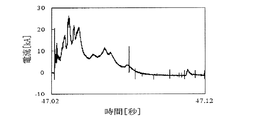
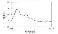
- the current waveform observed at Mt. Ogami shown in FIG. 7 has a frequency band limited to 90 Hz or less in order to compare with the magnetic field waveform observed by the search coil magnetometer. As shown in FIG. 7, the current increases to a maximum value of 26 kA after a small change and then decays.
- the integration of current corresponds to the amount of charge that has flowed due to lightning.
- the charge amount of the first positive polarity portion of the lightning strike shown in FIG. 7 is 474C, and the subsequent negative polarity portion is ⁇ 496C.
- the actual charge due to this lightning strike is estimated to be about 540C, slightly higher than the positive polarity part of the first half. Is done.
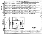
- Fig. 8 shows the waveform of the magnetic field component observed at Onagawa Station with the same lightning strike at Ogamidake.
- the polarity is positive in the southwest direction.
- the waveforms of both components are similar, and the ratio of the EW direction component to the NS direction component is about 0.70 as indicated by the black circle in FIG. 8 when the absolute value of the NS direction component exceeds 100 nT.
- the incident direction of the electromagnetic pulse based on the ratio is 54.8 ° west from the south, and is slightly coincident with the direction of Mt.
- the slight deviation of the azimuth is mainly due to the installation of the orthogonal magnetic field meter (magnetic field measuring unit 10), for example, the rotation of the magnetic field meter set in the horizontal plane, or the sensitivity calibration error.
- the influence of the induction noise of 50 Hz derived from a power wire is also considered.
- the direction of the lightning strike can be obtained from the waveform of each component of the magnetic field.
- the measurement accuracy of the lightning strike position can be improved by combining the direction of the lightning strike determined from the waveform of each component of the magnetic field with a lightning strike location system. Moreover, the position of a lightning strike can also be calculated
- the electromagnetic field was simulated when electromagnetic pulses from lightning propagated radially under the ionosphere.
- the FDTD method time domain difference method
- a cylindrical coordinate system was used as the coordinate system.
- the discharge path is simple and perpendicular to the ground, and the axial target condition in the cylindrical coordinate system is applied.
- the ionosphere of the earth and the multi-layer structure was assumed to be a horizontal parallel plate.
- the current waveform shown in FIG. 9 was used as the input current waveform.
- FIG. 10 shows a schematic diagram of a FDTD simulation of a cylindrical coordinate system for reproducing the propagation of an electromagnetic pulse of 296 km from the lightning generated at Ogamidake to Onagawa Observatory under the ionosphere.
- a simple lightning discharge path having a length of 4 km is installed on the ground surface along the vertical axis at the center of the simulation space.
- the electromagnetic field in the simulation space is excited by a horizontal magnetic field arranged in a magnetic field element Hy (0, 0) having a radius of 2 km around the discharge path.
- a positive current flowing downward along the discharge path generates a positive horizontal magnetic field at Hy (0, 0).
- the conductivity of the ground was uniformly 1 mS / m.
- the ionosphere consists of seven horizontal layers, and different conductivity ( ⁇ D, ⁇ N) was set for each layer for day and night. However, the relative permittivity ⁇ r and the relative permeability ⁇ r were the same as in the vacuum.
- the simulation space is surrounded by a PML absorption boundary, but the end walls are separated so that reflections there do not affect the observation point.
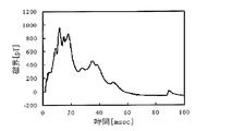
- Fig. 11 shows the simulation result of the horizontal magnetic field waveform at the distance of 298 km from the thunder corresponding to the Onagawa observation point.
- the waveform shown in FIG. 11 is very similar to the waveform of FIG. 9 and shows that it is almost occupied by the induction field. This is because the propagation distance is much shorter than the wavelength of radio waves of 3300 km at 90 Hz.
- the fluctuation of the first pulse of the magnetic field waveform shown in FIG. 8 to the negative polarity is deeper than the fluctuation of the magnetic field waveform shown in FIG. 11 to the negative polarity. This is because the cut-off frequency on the low frequency side of magnetic field observation is 2 Hz, which is higher than the cut-off frequency of 0.1 Hz on the low band of current observation.
- the peak value of the magnetic field obtained by the simulation was about 800 pT when ignoring the high-frequency change that cannot be seen in the observed waveform.
- the peak value of the observed magnetic field was composed of NS direction component and EW direction component, and was 480 pT.
- the observed peak value is as small as 0.6 of the peak value obtained by simulation.
- the amplitude of the magnetic field is proportional to the length of the discharge path, the actual discharge path length is estimated to be 2.4 km.
- the discharge path length obtained by other lightning strikes may be referred to.
- the magnetic field associated with a simple current pulse was determined at different distances.
- the lightning current was a Gaussian pulse with a peak value of 1 kA and a half width of 1, 2, 4 ms.
- the rising frequency of the Gaussian pulse is approximately 400, 200, and 100 Hz.
- FIG. 12 shows a horizontal magnetic field waveform with a propagation distance of 298 km, obtained by simulation assuming that the lightning current is a Gaussian pulse with a half width of 4 ms.
- the magnetic field waveform obtained by the simulation is very similar to the current waveform, regardless of the presence or absence of the ionosphere, except for a slight swing to negative polarity. This indicates that the current waveform and the magnetic field waveform are similar.
- the waveform of the electromagnetic field propagating under the ionosphere during the day and night has a signal intensity that is 4.3 times or 4.1 times that of the case without the ionosphere.
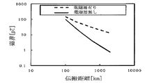
- FIG. 13 shows the relationship between the logarithmic peak value of the horizontal magnetic field pulse and the logarithmic propagation distance obtained by the simulation under the same conditions as in FIG. As shown in FIG. 13, the peak value is attenuated as the propagation distance is extended regardless of the presence or absence of the ionosphere.
- the average attenuation rate was -0.8 when the ionosphere was present and -1.6 when the ionosphere was absent. This indicates that the ionosphere has an effect of suppressing the attenuation of the magnetic field depending on the distance when there is no ionosphere to about 1/10.
- the attenuation factor of the magnetic field peak value was 1.8, as shown in FIG.
- a perfectly conductive vertical electric dipole on the ground generates a horizontal magnetic field on the ground surface, and the inductive and radiative components of the magnetic field attenuate in inverse proportion to the square and the first power of the distance from the dipole, respectively.
- the actual attenuation of the magnetic field is a mixture of attenuation of both components. This suggests that the magnetic field propagating between Ogamidake Ichinagawa Station is an inductive component whose attenuation is suppressed by the ionosphere.
- FIG. 14 shows the propagation distance dependence of the bipolar ratio of the magnetic field pulse obtained by the simulation when the half width of the current pulse is changed.
- the bipolar ratio of the magnetic field pulse is the absolute value of the ratio of the subsequent negative polarity peak to the first peak of the magnetic field waveform.
- FIG. 14 shows a simulation result in the daytime when there is an ionosphere. As shown in FIG. 14, the bipolar ratio increases to about 0.3 as the propagation distance increases. Further, when the half width of the current pulse increases, the curve of the bipolar ratio moves in parallel to the longer propagation distance. Under the condition that there is no ionosphere, since the bipolar ratio of the magnetic field pulse approaches 1 when the propagation distance is extended, it can be seen that the increase of the bipolar ratio is suppressed by the effect of the ionosphere.
- the half width of the current pulse is 4 ms corresponding to a cutoff frequency of 90 Hz and the propagation distance is 296 km. About 5%. This indicates that the difference between the current waveform and the waveform of the magnetic field pulse is small. From FIG. 14, the slight negative polarity swing after the peak of the magnetic field waveform can be improved by extending the low range of the observation frequency, thereby making the magnetic field waveform and the current waveform better match. I can say that.
- the original lightning current waveform can be easily reproduced from the magnetic field waveform in the range of the frequency and propagation distance where the bipolar ratio shown in FIG. 14 is sufficiently small.
- the reproduced current waveform composed of such low frequency components, it is possible to estimate the charge amount related to the equipment damage caused by lightning with high accuracy. That is, by integrating the reproduced current waveform, it is possible to estimate the amount of charge that has flowed due to a lightning strike.
- potential damage due to lightning strikes such as transmission line melting can be estimated. It is possible to provide materials for determining the necessity of damage countermeasures.
- the observation frequency is 100 Hz or less, the observation distance is 300 km or less, and the half-value width is 2 ms.
- the observation frequency is 200 Hz or less, the observation distance is 150 km or less, and the half-value width is 1 ms, the observation frequency is 400 Hz or less and the observation distance is 70 km or less.
- the observation frequency when the half width is 4 ms, the observation frequency is 100 Hz or less, the observation distance is 400 km or less, and when the half width is 2 ms, the observation frequency is 200 Hz or less, the observation distance is 250 km or less, and the half width. At 1 ms, the observation frequency is 400 Hz or less and the observation distance is 150 km or less.
- the ambivalence ratio is allowed up to 20%, when the half width is 4 ms, the observation frequency is 100 Hz or less, the observation distance is 1000 km or less, and when the half width is 2 ms, the observation frequency is 200 Hz or less, the observation distance is 500 km or less, and the half width is 1 ms. In this case, the observation frequency is 400 Hz or less and the observation distance is 300 km or less.
- the charge amount is obtained by integrating the current waveform, a rapid change in current (high frequency component) does not affect the charge amount. For this reason, considering that the current waveform having a duration of the order of several hundred ms is integrated, it is considered that a time resolution of several tens of ms is sufficient. Therefore, for example, when the current pulse width is about 10 ms, the observation frequency is about 25 Hz or less, and when the allowable bipolar ratio is 5%, the observation distance of the induced magnetic field is 800 km to 1000 km or less. In this case, for example, the whole of Japan can be covered with three observation points.
- the lightning current waveform when the discharge path is vertical is obtained.
- the actual length of the discharge path can be referred to the discharge path length obtained by other lightning strike observations.
- the obtained lightning current waveform is multiplied by 1 / cos ⁇ ( ⁇ is the inclination angle of the discharge path)
- ⁇ can be referred to an average value obtained by observation.
- the relationship between the lightning current waveform and the magnetic field waveform includes distortion, a highly reliable lightning current waveform is estimated by using the magnetic field waveform observed at a point with small distortion from FIG. Can do. By integrating the current waveform of the lightning strike thus obtained, the amount of charge that has flowed to the ground due to the lightning strike can be obtained.
- the amount of lightning strike was actually estimated from the magnetic field waveform of FIG.
- the peak value of the NS direction component of the observed magnetic field shown in FIG. 13 was 390 pT, and the peak value of the EW direction component was 270 pT. From these, the peak value of the combined magnetic field obtained from the square root of the sum of the square of the NS direction component and the square of the EW direction component is calculated as 480 pT. From FIG. 13, when the discharge path length of lightning generated at Ogamidake is 4 km and the current value is 1 kA, the magnetic field observed at Onagawa Observatory at a distance of 296 km from Ogamidake is 50 pT.
- the lightning strike charge amount estimation system 100 can appropriately estimate the lightning strike charge amount.
- the operation program stored in the memory 202 is a computer-readable recording medium such as a flexible disk, a CD-ROM (Compact Disk Read-Only Memory), a DVD (Digital Versatile Disk), or an MO (Magneto-Optical disk). It may be stored in and distributed.
- the function of the charge amount estimation system can also be realized by installing the operation program in the computer.
- the program may be stored in a disk device or the like included in a predetermined server device on a communication network such as the Internet, and may be downloaded onto a computer by being superimposed on a carrier wave, for example.
- the above-described functions can also be achieved by starting and executing a program while transferring it via a communication network.
- the above-described functions can be achieved by executing all or part of the program on the server device and executing the program while the computer transmits and receives information on the processing via the communication network.
- OS Operating System
- the above functions are realized by sharing an OS (Operating System) or when the functions are realized by cooperation between the OS and an application, only the part other than the OS may be stored in a medium and distributed. It may also be downloaded to a computer.
- the present invention can be widely used for estimating the amount of lightning strike.
Landscapes
- Environmental & Geological Engineering (AREA)
- Physics & Mathematics (AREA)
- Engineering & Computer Science (AREA)
- Life Sciences & Earth Sciences (AREA)
- Atmospheric Sciences (AREA)
- Biodiversity & Conservation Biology (AREA)
- Ecology (AREA)
- Environmental Sciences (AREA)
- Condensed Matter Physics & Semiconductors (AREA)
- General Physics & Mathematics (AREA)
- Measuring Magnetic Variables (AREA)
- Locating Faults (AREA)
Abstract
Description
前記磁界測定手段は、落雷により発生する磁界の2つの直交成分を測定可能であってもよい。この場合、落雷の電荷量推定システムは、前記磁界測定手段で測定された前記磁界の各成分に基づいて、前記落雷位置の方位を求める方位推定手段を有していてもよい。この場合、落雷位置標定システム等と組み合わせることにより、落雷位置の測定精度を高めることができる。
落雷により発生する磁界を測定するステップと、
測定された磁界に基づいて、落雷の電流を求めるステップと、
求められた電流を積分して落雷による電荷量を求めるステップと、
を有する。
コンピュータに、
測定された磁界に基づいて、落雷の電流を求めるステップと、
求められた電流を積分して落雷による電荷量を求めるステップと、
を実行させる。
図1に示すように、本実施の形態に係る落雷の電荷量推定システム100は、磁界測定部10と電荷量算出部20とを備える。
補正係数Kは次式で表される。
K=(放電路の実長/DL)*cosθ
ここで、放電路の実長は、落雷の発生地域、気象状況等に基づいて、統計処理、シミュレーション等により求められ、予め設定されている。
DLは、磁界電流比テーブル27に記憶されている磁界電流比Rを求める際に仮定した放電路の長さである。
θは、落雷の放電路の傾き角である。θは、落雷の発生地域、気象状況等に基づいて、統計処理、シミュレーション等により求められる。
なお、係数Kを地域と気象条件をパラメータとしてテーブルや関数の形態で表してもよい。
通信装置204は、ネットワークを介して外部装置と通信、落雷の発生したこと、落雷の地点を特定するための情報、電離層情報などを取り込む。
出力装置205は、求めた落雷の電荷量Qを出力する。
次に、CPU201は、メモリ202に記憶されている磁界電流比テーブル27から、電離層の状態と距離Lに合致する磁界電流比Rを求める(ステップS4)。
次に、CPU201は、落雷開始時点の合成磁界の強度Hを、メモリ202から順次読み出し(ステップS5)、磁界電流比Rとの積H・Rを求める(ステップS7)。これは、落雷開始時点で、落雷で流れた電流の平均値Iを示す。
さらに、CPU201は、乗算部29として、求めた電流の値Iに補正係数Kを乗算する。これにより、放電路の長さのばらつきや傾きが補正された電流値Iが求められる(ステップS8)。
ステップS11で、処理が終了していると判別されると(ステップS11;Yes)、求めた落雷による電荷量Qを出力する(ステップS13)。
ある落雷について、ロゴウスキーコイルおよびサーチコイル磁界計により観測を行った。ロゴウスキーコイルは、日本国新潟県の尾神岳(Mt.0gami)に設置されており、0.1Hz~1MHzの周波数帯域で、電波塔を流れる電流波形を観測可能になっている。観測された電流波形は、1μsでサンプリングされ、GPS時計でタイムスタンプされる。なお、観測に使用した落雷は、尾神岳で発生し、そこの電波塔を流れたものである。
雷による電磁パルスが電離層下を放射状に伝搬するときの、電磁界のシミュレーションを行った。シミュレーションには、様々な状況での雷に伴う電磁界のシミュレーションに適用されている、FDTD法(時間領域差分法)を使用した。また、座標系として、円筒座標系を使用した。放電路を大地に垂直な単純なものとし、円筒座標系での軸対象条件を適用した。また、大地および複数層構造の電離層を、水平の平行平板と仮定した。入力する電流波形として、図9に示す電流波形を使用した。
以上の落雷の観測および落雷に伴う電磁界のシミュレーションの結果に基づいて、測定された磁界波形から落雷の電荷量を求める具体的な手法の検討を行った。まず、方位推定手段や落雷位置標定システム等を利用して求められた落雷の位置から、磁界測定手段による磁界測定点までの距離を求め、その距離における磁界の大きさに対する雷電流の比を、図13から求める。その比を、磁界測定手段により測定された図8に示すような磁界波形に掛けると、放電路長が4kmの場合の雷電流波形が得られる。
また、プログラムをインターネット等の通信ネットワーク上の所定のサーバ装置が有するディスク装置等に格納しておき、例えば、搬送波に重畳させて、コンピュータにダウンロード等するようにしても良い。
また、通信ネットワークを介してプログラムを転送しながら起動実行することによっても、上述の機能を達成することができる。
更に、プログラムの全部又は一部をサーバ装置上で実行させ、その処理に関する情報をコンピュータが通信ネットワークを介して送受信しながらプログラムを実行することによっても、上述の機能を達成することができる。
なお、上述の機能を、OS(Operating System)が分担して実現する場合又はOSとアプリケーションとの協働により実現する場合等には、OS以外の部分のみを媒体に格納して配布してもよく、また、コンピュータにダウンロード等しても良い。
20 電荷量算出部
21 A/D変換器
22 ローパスフィルタ(LPF)
23 RTC
24 記憶部
25 距離判別部
26 電離層情報収集部
27 磁界電流比テーブル
28 電流計算部
29 乗算部
30 積分部(累算部)
100 落雷の電荷量推定システム
201 CPU
202 メモリ
203 入力装置
204 通信装置
205 出力装置
Claims (10)
- 200Hz以下の周波数を含む周波数帯域で、落雷により発生する磁界を測定する磁界測定手段と、
前記磁界測定手段で測定された磁界に基づいて、前記落雷の電流を求め、その電流を積分して電荷量を求める電荷量算出手段と、
を有することを特徴とする落雷の電荷量推定システム。 - 前記周波数帯域は、100Hz以下の周波数を含むことを特徴とする請求項1に記載の落雷の電荷量推定システム。
- 前記磁界測定手段で測定された磁界に、高周波数側のカットオフ周波数が100Hzのフィルタをかけるフィルタ手段を有し、
前記電荷量算出手段は、前記フィルタ手段でフィルタをかけた後の磁界に基づいて電荷量を求めることを特徴とする請求項1または2に記載の落雷の電荷量推定システム。 - 前記磁界測定手段は、落雷により発生する磁界の2つの直交成分を測定し、
前記磁界測定手段で測定された前記磁界の各成分に基づいて、前記落雷の方向を求める方位推定手段を更に有する、
ことを特徴とする請求項1乃至3のいずれか1項に記載の落雷の電荷量推定システム。 - 前記磁界測定手段は、測定された磁界が初期の極性と逆の極性の値を含まないよう、測定対象の周波数帯域に低周波領域を含んでいることを特徴とする請求項1乃至4のいずれか1項に記載の落雷の電荷量推定システム。
- 前記電荷量算出手段は、磁界または磁界に基づいて求めた電流が初期の極性と逆の極性の値を含まないよう補正した後、電荷量を求めることを特徴とする請求項1乃至5のいずれか1項に記載の落雷の電荷量推定システム。
- 前記電荷量算出手段は、
測定された磁界に、予め設定されている磁界電流変換係数を乗算することにより落雷の電流を求める手段と、
求めた電流に、放電路の長さと傾きに基づく補正係数を乗算する手段と、
補正係数が乗算された電流を積分する積分手段と、
を有することを特徴とする請求項1乃至6のいずれか1項に記載の落雷の電荷量推定システム。 - 前記磁界電流変換係数は、落雷地点から磁界測定地点までの距離に依存する磁界の減衰と電離層の状態に依存する磁界の減衰との少なくとも一方を考慮して設定されている、
ことを特徴とする請求項7に記載の落雷の電荷量推定システム。 - 落雷により発生する磁界を測定するステップと、
測定された磁界に基づいて、落雷の電流を求めるステップと、
求められた電流を積分して落雷による電荷量を求めるステップと、
を有することを特徴とする落雷の電荷量推定方法。 - コンピュータに、
測定された磁界に基づいて、落雷の電流を求めるステップと、
求められた電流を積分して落雷による電荷量を求めるステップと、
を実行させるコンピュータプログラム。
Priority Applications (3)
| Application Number | Priority Date | Filing Date | Title |
|---|---|---|---|
| EP13855352.4A EP2921887B1 (en) | 2012-11-15 | 2013-11-14 | Lightning-strike electric charge estimation system and method |
| JP2014547040A JP6067741B2 (ja) | 2012-11-15 | 2013-11-14 | 落雷の電荷量推定システム、落雷の電荷量推定方法、及び、プログラム |
| US14/443,002 US20150293264A1 (en) | 2012-11-15 | 2013-11-14 | Lightning-strike electric charge estimation system and method |
Applications Claiming Priority (2)
| Application Number | Priority Date | Filing Date | Title |
|---|---|---|---|
| JP2012251493 | 2012-11-15 | ||
| JP2012-251493 | 2012-11-15 |
Publications (1)
| Publication Number | Publication Date |
|---|---|
| WO2014077337A1 true WO2014077337A1 (ja) | 2014-05-22 |
Family
ID=50731246
Family Applications (1)
| Application Number | Title | Priority Date | Filing Date |
|---|---|---|---|
| PCT/JP2013/080836 Ceased WO2014077337A1 (ja) | 2012-11-15 | 2013-11-14 | 落雷の電荷量推定システムと方法 |
Country Status (4)
| Country | Link |
|---|---|
| US (1) | US20150293264A1 (ja) |
| EP (1) | EP2921887B1 (ja) |
| JP (1) | JP6067741B2 (ja) |
| WO (1) | WO2014077337A1 (ja) |
Cited By (7)
| Publication number | Priority date | Publication date | Assignee | Title |
|---|---|---|---|---|
| JP2017009507A (ja) * | 2015-06-24 | 2017-01-12 | 東京電力ホールディングス株式会社 | 雷害判定装置、及び雷害判定システム |
| JP2017156282A (ja) * | 2016-03-03 | 2017-09-07 | 一般財団法人電力中央研究所 | 電荷量の推定方法、推定装置、及び推定プログラム |
| JP2017156158A (ja) * | 2016-02-29 | 2017-09-07 | 株式会社フランクリン・ジャパン | 落雷位置標定システム、落雷位置標定装置、及び落雷位置標定方法 |
| JP2017181039A (ja) * | 2016-03-28 | 2017-10-05 | 一般財団法人電力中央研究所 | 落雷電流特性値の推定方法、推定装置、及び推定プログラム |
| JP2019002740A (ja) * | 2017-06-13 | 2019-01-10 | 国立大学法人静岡大学 | 落雷電荷量推定方法及びシステム |
| JP2020079724A (ja) * | 2018-11-12 | 2020-05-28 | 北陸電力株式会社 | 落雷電流波形推定方法および落雷電流波形推定装置 |
| WO2026014090A1 (ja) * | 2024-07-10 | 2026-01-15 | 株式会社村田製作所 | 落雷予測システムおよび落雷予測方法 |
Families Citing this family (6)
| Publication number | Priority date | Publication date | Assignee | Title |
|---|---|---|---|---|
| FR3051442B1 (fr) * | 2016-05-20 | 2021-07-16 | Airbus Operations Sas | Systeme embarque d'evaluation de la severite d'un foudroiement |
| CN111400910B (zh) * | 2020-03-16 | 2022-06-07 | 西安交通大学 | 四角塔通信基站系统的雷电流分流特性计算方法 |
| CN111896795B (zh) * | 2020-07-16 | 2023-01-03 | 中国人民解放军陆军工程大学 | 云闪电流波形测量方法及系统 |
| CN113848374A (zh) * | 2021-10-22 | 2021-12-28 | 云南电网有限责任公司电力科学研究院 | 一种考虑地球曲率半径影响的超远距离雷电强度反演算法 |
| CN114814960B (zh) * | 2022-03-11 | 2024-11-26 | 中国科学院电工研究所 | 基于单站检测的闪电电磁波定位方法、系统及设备 |
| CN119438717B (zh) * | 2024-11-20 | 2025-08-22 | 中国科学技术大学 | 一种融合雷电能量参数的闪电定位网 |
Citations (3)
| Publication number | Priority date | Publication date | Assignee | Title |
|---|---|---|---|---|
| JPH07151866A (ja) * | 1993-08-04 | 1995-06-16 | Agency Of Ind Science & Technol | 雷電探知方法及び雷電探知装置 |
| JP2006194643A (ja) | 2005-01-11 | 2006-07-27 | Tohoku Electric Power Co Inc | 落雷位置標定方法及びシステム |
| JP2006275845A (ja) * | 2005-03-30 | 2006-10-12 | Toko Electric Corp | 雷撃電流計測装置 |
Family Cites Families (6)
| Publication number | Priority date | Publication date | Assignee | Title |
|---|---|---|---|---|
| US6791311B2 (en) * | 2002-02-13 | 2004-09-14 | Vaisala Oyj | Lightning detection and data acquisition system |
| US20080122424A1 (en) * | 2005-01-24 | 2008-05-29 | Yongming Zhang | Integrated Sensor System Monitoring and Characterizing Lightning Events |
| US8427333B2 (en) * | 2009-06-29 | 2013-04-23 | General Electric Company | System and method for detecting lightning |
| US8203814B2 (en) * | 2009-08-31 | 2012-06-19 | Eaton Corporation | Electrical switching apparatus including a plurality of Rogowski coils and method of calibrating the same |
| US8005617B2 (en) * | 2010-11-29 | 2011-08-23 | General Electric Company | System and method for detecting lightning strikes likely to affect a condition of a structure |
| US9835141B2 (en) * | 2011-07-28 | 2017-12-05 | Vestas Wind Systems A/S | Wind turbine blade and a lightning measurement system therein |
-
2013
- 2013-11-14 EP EP13855352.4A patent/EP2921887B1/en active Active
- 2013-11-14 US US14/443,002 patent/US20150293264A1/en not_active Abandoned
- 2013-11-14 JP JP2014547040A patent/JP6067741B2/ja active Active
- 2013-11-14 WO PCT/JP2013/080836 patent/WO2014077337A1/ja not_active Ceased
Patent Citations (3)
| Publication number | Priority date | Publication date | Assignee | Title |
|---|---|---|---|---|
| JPH07151866A (ja) * | 1993-08-04 | 1995-06-16 | Agency Of Ind Science & Technol | 雷電探知方法及び雷電探知装置 |
| JP2006194643A (ja) | 2005-01-11 | 2006-07-27 | Tohoku Electric Power Co Inc | 落雷位置標定方法及びシステム |
| JP2006275845A (ja) * | 2005-03-30 | 2006-10-12 | Toko Electric Corp | 雷撃電流計測装置 |
Non-Patent Citations (2)
| Title |
|---|
| CUMMER A.: "UNUSUALLY INTENSE CONTINUING CURRENT IN LIGHTNING PRODUCES DELAYED MESOSPHERIC BBREAKDOWN", GEOPHYSICAL RESEARCH LETTERS, vol. 28, no. 3, 1 February 2001 (2001-02-01), pages 495 - 498, XP055254486 * |
| HIRONAO KAWAMURA: "OBSERVATION OF WINTER LIGHTNING AND ITS CHARACHTERISTICS IN THE HOKURIKU AREA WITH UTILIZING ELECTROMAGNETIC WAVE 1 SEARCHING FOR NATURE SECRETS IN THE HOKURIKU DISTINCT ELECTRONICS WAVES AS A TOOL FOR DISCOVERY", JOURNAL OF THE INSTITUTE OF ELECTRONICS INFORMATION AND COMMUNICATION, vol. 93, no. 10, 1 October 2010 (2010-10-01), pages 828 - 830, XP008179239 * |
Cited By (8)
| Publication number | Priority date | Publication date | Assignee | Title |
|---|---|---|---|---|
| JP2017009507A (ja) * | 2015-06-24 | 2017-01-12 | 東京電力ホールディングス株式会社 | 雷害判定装置、及び雷害判定システム |
| JP2017156158A (ja) * | 2016-02-29 | 2017-09-07 | 株式会社フランクリン・ジャパン | 落雷位置標定システム、落雷位置標定装置、及び落雷位置標定方法 |
| JP2017156282A (ja) * | 2016-03-03 | 2017-09-07 | 一般財団法人電力中央研究所 | 電荷量の推定方法、推定装置、及び推定プログラム |
| JP2017181039A (ja) * | 2016-03-28 | 2017-10-05 | 一般財団法人電力中央研究所 | 落雷電流特性値の推定方法、推定装置、及び推定プログラム |
| JP2019002740A (ja) * | 2017-06-13 | 2019-01-10 | 国立大学法人静岡大学 | 落雷電荷量推定方法及びシステム |
| JP2020079724A (ja) * | 2018-11-12 | 2020-05-28 | 北陸電力株式会社 | 落雷電流波形推定方法および落雷電流波形推定装置 |
| JP7133442B2 (ja) | 2018-11-12 | 2022-09-08 | 北陸電力株式会社 | 落雷電流波形推定方法および落雷電流波形推定装置 |
| WO2026014090A1 (ja) * | 2024-07-10 | 2026-01-15 | 株式会社村田製作所 | 落雷予測システムおよび落雷予測方法 |
Also Published As
| Publication number | Publication date |
|---|---|
| EP2921887B1 (en) | 2018-07-04 |
| EP2921887A1 (en) | 2015-09-23 |
| JPWO2014077337A1 (ja) | 2017-01-05 |
| EP2921887A4 (en) | 2016-06-22 |
| JP6067741B2 (ja) | 2017-01-25 |
| US20150293264A1 (en) | 2015-10-15 |
Similar Documents
| Publication | Publication Date | Title |
|---|---|---|
| JP6067741B2 (ja) | 落雷の電荷量推定システム、落雷の電荷量推定方法、及び、プログラム | |
| US7467049B2 (en) | System and method for detecting impaired electric power equipment | |
| CN106019287B (zh) | 一种基于小型雷达的输电线路雷电监测预警方法 | |
| CN107748317B (zh) | 一种地下电缆高阻故障的精确定位系统 | |
| US8868361B2 (en) | Hand-held system and method for detecting impaired electric power equipment | |
| US8768636B2 (en) | System and method for detecting impaired electric power equipment | |
| Lu et al. | Characterization of initial current pulses in negative rocket‐triggered lightning with sensitive magnetic sensor | |
| US10175286B1 (en) | Power line fault locating system | |
| Samanes et al. | Estimating the VLF modal interference distance using the South America VLF Network (SAVNET) | |
| Narita et al. | A study of lightning location system (Blitz) based on VLF sferics | |
| Sidik et al. | Lightning monitoring system for sustainable energy supply: A review | |
| JP4817665B2 (ja) | 落雷位置標定方法及びシステム | |
| CN108414908A (zh) | 一种阴极保护绝缘测试仪及其测试方法 | |
| Salimi et al. | Investigation of short base line lightning detection system by using time of arrival method | |
| Kumar et al. | Nighttime D-region equivalent electron density determined from tweek sferics observed in the South Pacific Region | |
| Herodotou et al. | Distribution of lightning peak stroke currents in Ontario using an LLP system | |
| Shi et al. | Investigation on the lightning location and warning system using artificial intelligence | |
| JP6343863B1 (ja) | 地震予測システム、及び地震予測方法 | |
| Kohlmann et al. | Analysis of lightning-induced currents in supply cable shields and their impact on LLS sensor site errors | |
| Tofani et al. | Lightning Activity Evaluation in South Sumatera Region | |
| Kang et al. | Detection and characterization algorithm of swept continuous wave interference for safe GBAS operation | |
| Galván et al. | A technique for the evaluation of lightning-induced voltages in complex low-voltage power-installation networks | |
| Kurihara et al. | A verification of estimation accuracy of lightning current waveform and charge transfer from measured E‐field waveform | |
| Dolea et al. | In-situ measurements regarding LF radio wave propagation using DCF77 time signal transmitter | |
| Anuar et al. | Development of an Lf Station for a Real-Time Lightning Detection System in Malaysia |
Legal Events
| Date | Code | Title | Description |
|---|---|---|---|
| 121 | Ep: the epo has been informed by wipo that ep was designated in this application |
Ref document number: 13855352 Country of ref document: EP Kind code of ref document: A1 |
|
| WWE | Wipo information: entry into national phase |
Ref document number: 14443002 Country of ref document: US |
|
| ENP | Entry into the national phase |
Ref document number: 2014547040 Country of ref document: JP Kind code of ref document: A |
|
| NENP | Non-entry into the national phase |
Ref country code: DE |
|
| WWE | Wipo information: entry into national phase |
Ref document number: 2013855352 Country of ref document: EP |