WO2014080532A1 - スライドファスナー用スライダー - Google Patents
スライドファスナー用スライダー Download PDFInfo
- Publication number
- WO2014080532A1 WO2014080532A1 PCT/JP2012/080514 JP2012080514W WO2014080532A1 WO 2014080532 A1 WO2014080532 A1 WO 2014080532A1 JP 2012080514 W JP2012080514 W JP 2012080514W WO 2014080532 A1 WO2014080532 A1 WO 2014080532A1
- Authority
- WO
- WIPO (PCT)
- Prior art keywords
- flange
- slider
- handle holder
- slider body
- slide fastener
- Prior art date
- Legal status (The legal status is an assumption and is not a legal conclusion. Google has not performed a legal analysis and makes no representation as to the accuracy of the status listed.)
- Ceased
Links
Images






Classifications
-
- A—HUMAN NECESSITIES
- A44—HABERDASHERY; JEWELLERY
- A44B—BUTTONS, PINS, BUCKLES, SLIDE FASTENERS, OR THE LIKE
- A44B19/00—Slide fasteners
- A44B19/24—Details
- A44B19/26—Sliders
- A44B19/262—Pull members; Ornamental attachments for sliders
-
- A—HUMAN NECESSITIES
- A44—HABERDASHERY; JEWELLERY
- A44B—BUTTONS, PINS, BUCKLES, SLIDE FASTENERS, OR THE LIKE
- A44B19/00—Slide fasteners
- A44B19/24—Details
- A44B19/26—Sliders
- A44B19/30—Sliders with means for locking in position
- A44B19/308—Sliders with means for locking in position in the form of a spring-actuated locking member actuated by the pull member
-
- F—MECHANICAL ENGINEERING; LIGHTING; HEATING; WEAPONS; BLASTING
- F16—ENGINEERING ELEMENTS AND UNITS; GENERAL MEASURES FOR PRODUCING AND MAINTAINING EFFECTIVE FUNCTIONING OF MACHINES OR INSTALLATIONS; THERMAL INSULATION IN GENERAL
- F16B—DEVICES FOR FASTENING OR SECURING CONSTRUCTIONAL ELEMENTS OR MACHINE PARTS TOGETHER, e.g. NAILS, BOLTS, CIRCLIPS, CLAMPS, CLIPS OR WEDGES; JOINTS OR JOINTING
- F16B2/00—Friction-grip releasable fastenings
- F16B2/02—Clamps, i.e. with gripping action effected by positive means other than the inherent resistance to deformation of the material of the fastening
- F16B2/06—Clamps, i.e. with gripping action effected by positive means other than the inherent resistance to deformation of the material of the fastening external, i.e. with contracting action
- F16B2/10—Clamps, i.e. with gripping action effected by positive means other than the inherent resistance to deformation of the material of the fastening external, i.e. with contracting action using pivoting jaws
-
- Y—GENERAL TAGGING OF NEW TECHNOLOGICAL DEVELOPMENTS; GENERAL TAGGING OF CROSS-SECTIONAL TECHNOLOGIES SPANNING OVER SEVERAL SECTIONS OF THE IPC; TECHNICAL SUBJECTS COVERED BY FORMER USPC CROSS-REFERENCE ART COLLECTIONS [XRACs] AND DIGESTS
- Y10—TECHNICAL SUBJECTS COVERED BY FORMER USPC
- Y10T—TECHNICAL SUBJECTS COVERED BY FORMER US CLASSIFICATION
- Y10T24/00—Buckles, buttons, clasps, etc.
- Y10T24/25—Zipper or required component thereof
- Y10T24/2561—Slider having specific configuration, construction, adaptation, or material
- Y10T24/2586—Slider having specific configuration, construction, adaptation, or material including pull tab attaching means
Definitions
- the present invention relates to a slider for a slide fastener, and more particularly to a slider for a slide fastener that greatly improves the assembling property of a handle holder and a slider body and has high production efficiency.
- the slide fastener slider described in Patent Document 1 After the flange provided on the handle holder is fitted into the slide groove of the slider body, the caulking build-up portion provided on the slider body is placed on the upper surface side.
- the flange of the handle holder is crimped and fixed to the upper wing plate of the slider body by crushing with a punch or the like, thereby simplifying the operation of attaching the handle holder to the slider body.
- a part of the side wall portion of the handle holder is pressed toward the concave portion of the slider body, and the raised portion formed on the upper blade is used as a flange of the handle holder.
- the mounting strength between the handle holder and the slider body is improved by pressing toward the fixing concave portion provided and crimping and fixing the handle holder to the slider body at two locations.
- the present invention has been made in view of the above-described circumstances, and an object of the present invention is to improve the workability when attaching the handle holding body to the slider body, and has a strong mounting strength and a good appearance. To provide a slider.
- a slider fuselage having an upper blade and a lower blade that are vertically opposed to each other, and an element guide path provided between the upper blade and the lower blade;
- a handle having a mounting shaft, One end is fixed to the upper wing plate of the slider body in a cantilevered manner, and a handle holding body that holds the attachment shaft portion of the handle,
- a slide fastener slider comprising:
- the handle holder has a flange extending in the width direction from the left and right side surfaces of the one end and extending in the longitudinal direction,
- the slider fuselage is formed at the front end of the upper blade, and has a sliding groove that accommodates the flange.
- One of the handle holding body and the slider body has a convex portion protruding toward the other of the handle holding body and the slider body,
- the other of the handle holder and the slider body has a concave portion that engages with the convex portion
- the flange is inserted into the sliding groove, and the upper surface of the upper blade located above the sliding groove is caulked toward the flange, so that the convex part is engaged with the concave part and the handle holder is fixed to the slider body.
- a slide fastener slider characterized by that.
- (2) The slide fastener slider according to (1), wherein the upper surface of the flange is an inclined surface that is inclined so that the thickness of the flange gradually decreases from the rear end portion to the front end portion of the flange.
- the upper surface of the flange is formed such that the thickness of the flange gradually decreases from the root portion side to the side surface side of the flange,
- the upper surface of the sliding groove portion of the slider body gradually decreases in correspondence with the upper surface of the flange as the upper surface portion of the upper blade located above the sliding groove portion moves from the root portion side to the side surface side.
- the convex portion is formed to protrude toward the slider body on the lower surface of the one end portion of the handle holder, The concave portion is formed on the upper surface of the front end portion of the upper blade, The slide fastener slider according to any one of (1) to (4).
- the convex portion is formed to protrude toward the handle holder on the upper surface of the front end portion of the upper blade, The concave portion is formed on a lower surface of one end portion of the pull holder, and the slide fastener slider according to any one of (1) to (4).
- the convex portion is formed on the lower surface of the flange of the handle holder, The concave portion is formed on the lower surface of the sliding groove, and the slider for a slide fastener according to any one of (1) to (4).
- a stop claw body that is disposed so as to be able to swing up and down by a claw body support portion erected from the upper wing plate, and that has a claw portion that can be moved into and out of the element guide path from a claw hole formed in the upper wing plate
- a pivot pin having both ends held by a support groove formed in the nail body support portion and supporting the stop nail body in a swingable manner; Further comprising
- the convex portion is a stepped portion that projects downward from the lower surface of the inner wall of the handle holder and contacts the pivot pin,
- the concave portion is a support groove that holds both ends of the pivot pin and engages with the stepped portion, and the slider for a slide fastener according to any one of (1) to (4).
- the handle holder has a flange extending in the width direction from the left and right side surfaces of the one end portion and extending in the longitudinal direction, and the slider body is disposed at the front end portion of the upper wing plate.
- the flange is inserted into the sliding groove portion and the upper surface portion of the upper blade is caulked toward the flange, the vertical direction of the handle holder and the slider body is fixed by caulking, and the relationship between the convex portion and the concave portion is fixed. As a result, the front-rear direction of the handle holder and the slider body is fixed. In addition, since the entire flange is crimped, the mounting strength can be increased, and no caulking trace is left on the handle holder and the appearance is improved.
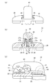
- FIG. 1 It is a disassembled perspective view of the slider for slide fasteners of 1st Embodiment which concerns on this invention.
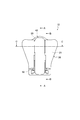
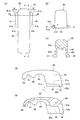
- FIG. 1 is a front view of the handle holder shown in FIG. 1
- (b) is a front view of the handle holder
- (c) is a sectional view taken along line DD of (a).
- (D) is a side view of the handle holder
- (e) is a cross-sectional view taken along the line EE of (a).
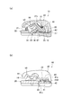
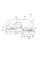
- 2A is a cross-sectional view of the main part along the line AA in FIG. 2, showing the state of the slider body and the handle holding body at the start of assembly, and FIG. It is principal part sectional drawing along a line.
- FIG. 1 is a cross-sectional view of the main part along the line AA in FIG. 2 showing the state of the slider body and the handle holder during assembly
- (b) is a cross-sectional view along the line BB in FIG. It is principal part sectional drawing along.
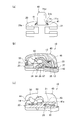
- (A) is a front view showing a state before caulking when the handle holder is assembled to the slider body
- (b) is a cross-sectional view of the main part along the line AA in FIG. 2
- FIG. 3 is a cross-sectional view of a principal part taken along line BB in FIG.
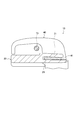
- (A) is a principal part front view which shows the state of the slider body and the handle holding body after caulking
- (b) is a principal part sectional view along CC line of FIG.
- FIG. 3 c is a cross-sectional view of the main part along the line BB in FIG.
- (A)-(c) is principal part sectional drawing which shows the slider for slide fasteners of a 1st modification according to an assembly
- (A)-(c) is principal part sectional drawing which shows the slider for slide fasteners of a 2nd modification according to an assembly
- FIG.7 (c) of the slider for slide fasteners of a 4th modification It is principal part sectional drawing equivalent to FIG.6 (b) of the slider for slide fasteners of a 5th modification.
- (A) to (f) are cross-sectional views taken along the line CC of FIG. 2, showing first to sixth examples of sliders for slide fasteners according to a sixth modification. It is principal part sectional drawing of the slider for slide fasteners of a 7th modification. It is principal part sectional drawing of the slider for slide fasteners of an 8th modification.
- the side where the width of the slider is wide and the fastener element separates and exits is referred to as the shoulder opening side
- the side where the width of the slider is narrow and the fastener element engages and exits Is the rear side.
- the shoulder side is the front
- the rear side is the back
- the slider sliding direction is the front-rear direction
- the direction orthogonal to the front-rear direction and parallel to the unillustrated fastener tape is the left-right direction (width direction), front-rear direction, and left-right direction
- the direction orthogonal to the vertical direction is defined as the vertical direction.
- the slide fastener slider 10 mainly includes a slider body 20, a handle holding body 40, an opening / closing member 50, a stop claw body 60, and a handle 70. It is configured.
- the handle holding body 40 and the stop claw body 60 are made of a metal material such as stainless steel, copper alloy or zinc alloy, and the slider body 20 and the opening / closing member 50 are made of a metal material such as aluminum alloy or zinc alloy by press molding or die. Manufactured by casting.
- the handle holding body 40, the slider body 20, and the opening / closing member 50 are made of zinc die casting, and the stop claw body 60 is made of copper alloy.
- these parts can be manufactured by injection molding a thermoplastic resin material such as polyamide, polypropylene, polyacetal, or polybutylene terephthalate instead of the metal material.
- the slider body 20 includes an upper wing plate 21, a lower wing plate 22, and a guide column 23 that connects the front end portions of the upper wing plate 21 and the lower wing plate 22, It is integrally formed.
- Upper and lower flanges 21 a and 22 a are provided on the left and right sides of the upper wing plate 21 and the lower wing plate 22 from the rear end to a substantially central position.
- the slider body 20 has a Y-shaped element guide path 24 formed between an upper wing plate 21 and a lower wing plate 22, a rear opening 25 at the rear end of the element guide path 24, and two at the front end.
- a shoulder opening 26 is provided.
- the slider body 20 is formed with a nail body support portion 27 including left and right wall portions 27 a and 27 b that are erected and spaced apart from each other at an interval where the stop claw body 60 can be accommodated. .
- a nail body support portion 27 including left and right wall portions 27 a and 27 b that are erected and spaced apart from each other at an interval where the stop claw body 60 can be accommodated.
- U-shaped grooves 27c that hold the pivot pins 13 that pivotally support the stop claw body 60 so as to swing up and down are formed to open upward.
- a spring chamber 35 is provided between the left and right wall portions 27 a and 27 b to accommodate the leaf spring 12 described later.
- a positioning projection 36 for positioning the stop claw body 60 is formed on the rear end side of the spring chamber 35 (see FIG. 5A).
- the slider body 20 has a fitting portion 28 that is recessed in front of the claw body support portion 27 of the upper wing plate 21, and both the left and right sides of the fitting portion 28 along the length direction of the slider body 20. And a sliding groove 29 that is linearly recessed from the front end of the upper blade 21 to the rear side of the left and right walls 27a and 27b of the claw support 27. A flange 41 (to be described later) of the handle holder 40 is accommodated in the sliding groove 29.
- a concave portion 30 that can be engaged with a convex portion 42 of a pull handle holder 40 described later is formed on the front end side of the nail body support portion 27 at the intermediate portion in the width direction of the fitting portion 28.
- the concave portion 30 is formed continuously with the spring chamber 35 formed between the left and right wall portions 27a and 27b of the claw support portion 27.
- the slider body 20 is formed with a claw hole 31 penetrating from the upper surface of the upper blade 21 to the element guide path 24 behind the claw body support portion 27.
- an opening / closing member guide groove 32 into which the opening / closing member 50 is slidably fitted is formed from the rear end of the upper blade 21 to the left and right sides of the claw hole 31.
- a spring mounting groove 33 for mounting the coil spring 11 is formed on a part of the bottom surface of the opening / closing member guide groove 32.
- projecting piece portions 34 projecting from the bottom surface of the opening / closing member guide groove 32 are provided on both the left and right sides. After the projecting piece portion 34 is fitted into the opening / closing member guide groove 32, the projecting piece portion 34 is pushed and bent toward the center portion in the width direction of the slider body 20, so that the opening / closing member 50 is opened and closed. It functions as a stopper that prevents the groove 32 from falling off.
- the handle holder 40 is formed in a bottomed box shape having a substantially L shape in side view and having an opening on one side, and a fixed-side base end portion 43, which is one end of the handle holder 40, is formed.
- the upper wing plate 21 is fixed to the front portion of the upper surface and attached to the slider body 20 in a cantilever manner.
- a gap 14 is formed between the rear end portion 44, which is the other end portion of the handle holder 40, and the slider body 20 (see FIG. 6B).
- a pair of left and right flanges 41 accommodated in the sliding groove 29 of the slider body 20 are formed on the lower edge portions of the left and right side surfaces of the fixed base end portion 43 of the handle holder 40.
- the upper surface 41a of the flange 41 is an inclined surface where the thickness t of the flange 41 gradually decreases from the rear end portion 41c of the flange 41 toward the front end portion 41d.
- the upper surface 41a of the flange 41 is also an inclined surface that is inclined so that the thickness t of the flange 41 gradually decreases from the root portion 41f of the flange 41 toward the side surface 41b.
- both side surfaces 41b of the flange 41 are formed to be inclined so that the width W gradually increases from the rear end portion 41c of the flange 41 toward the front end portion 41d.
- the groove height L of the sliding groove 29 before caulking that accommodates the flange 41 is uniformly formed in the front-rear direction as shown in FIG. . 6A
- the upper surface 29a of the sliding groove 29 of the slider body 20 corresponds to the upper surface 41a of the flange 41
- the portion 21b is inclined so that the wall thickness ta of the upper surface portion 21b gradually decreases from the base portion 21c toward the side surface 21d.
- the handle holder 40 is provided with a convex portion 42 having a substantially triangular cross section that protrudes downward from the lower surface 43a on the front end portion side of the fixed base end portion 43.
- the front end wall 42a of the convex portion 42 is formed substantially perpendicular to the lower surface 43a, and the rear end wall 42b is formed inclined with respect to the lower surface 34a.
- the fixed-side base end portion 43 includes a slider body including an upper surface portion 45 that continues to the rear end portion 44 side, a front wall portion 43b that continuously extends forward from the upper surface portion 45, and left and right side wall portions 43c and 43d.
- the inner wall 20 is formed so as to cover the nail body support portion 27, and in the portion surrounded by the upper surface portion 45, the front wall portion 43b, and the left and right side wall portions 43c and 43d, the inner wall is bulged downward.
- a protruding portion 43e is provided.
- a stepped portion 46 that protrudes downward from the center in the left-right direction is provided on the lower surface of the bulging portion 43 e.
- a retracting portion 47 and a housing portion 48 are formed in a downwardly facing concave shape facing the slider body 20, and the retracting portion 47 and the housing portion are accommodated.
- the part 48 is continuous by a convex continuous edge part 49.
- the opening / closing member 50 has a substantially U-shaped planar shape, and is attached to the upper blade 21 (opening / closing member guide groove 32) of the slider body 20 and slides toward the front end side. When doing so, interference with the claw hole 31 is prevented.
- the opening / closing member 50 is provided with a guide portion 51 slidably fitted in the opening / closing member guide groove 32 of the upper blade 21 at the lower part of the left and right side edge portions.
- the bifurcated arm portion of the opening / closing member 50 has a proximal end side closing portion 52 and a distal end side closing portion 53 formed in a convex shape upward.
- the stop claw body 60 has a claw body base end portion 61, and an upper arm portion 62 and a lower arm portion 63 that branch from the claw body base end portion 61 into two branches and extend substantially in parallel.
- a claw portion 64 that protrudes into the element guide path 24 through the claw hole 31 of the slider body 20 is formed at the tip of the side arm portion 63.
- an operating groove 65 that opens toward the rear opening 25 of the slider body 20 is provided between the upper and lower arm portions 62 and 63.
- a pivot recess 66 that pivots on the pivot pin 13 held at both ends in the U-shaped groove 27 c of the nail body support portion 27 is formed.
- a lower recess 67 is provided in the lower part.
- the handle 70 has an annular portion 71 into which the handle holder 40 is inserted at one end side, and a handle portion 72 from the annular portion 71 to the other end side.
- An attachment shaft portion 73 having a circular cross section is disposed at the tip of the annular portion 71.
- the length of the attachment shaft portion 73 is set to be larger than the width dimension of the handle holder 40.
- the opening / closing member 50 and the coil spring 11 are assembled to the slider body 20. Specifically, after the coil spring 11 is mounted in the spring mounting groove 33 formed on the upper blade 21 of the slider body 20, the guide portion 51 of the opening / closing member 50 is fitted into the opening / closing member guide groove 32 of the upper blade 21. And insert. Further, in a state where the opening / closing member 50 is pushed in and the coil spring 11 is contracted, the projecting piece portions 34 provided on both sides of the opening / closing member guide groove 32 are pushed and bent toward the center in the width direction of the slider body 20. Accordingly, the opening / closing member 50 and the coil spring 11 are prevented from falling off the upper blade 21 of the slider body 20. The opening / closing member 50 is attached to the slider body 20 so as to be slidable along the opening / closing member guide groove 32 while being always urged rearward by the elastic force of the coil spring 11.
- the leaf spring 12, the stop claw body 60, the pivot pin 13, and the handle holder 40 are assembled in this order to the slider body 20 to which the opening / closing member 50 and the coil spring 11 are assembled.
- the leaf spring 12 formed in a rectangular shape by a spring steel plate is inserted into the spring chamber 35 provided between the left and right wall portions 27a and 27b of the claw support portion 27.
- the stop claw body 60 is inserted between the left and right wall portions 27a and 27b from above while engaging the lower concave portion 67 of the stop claw body 60 and the positioning convex portion 36.
- the pivot pin 13 is fitted into the U-shaped groove 27 c of the nail body support portion 27 and placed on the pivot recess 66 of the stop nail body 60.
- the leaf spring 12 and the pivot pin 13 are swaged and fixed to the claw support portion 27 so that these parts do not come off even if the pull handle holder 40 contacts. It is desirable to keep it.
- the flange 41 of the handle holder 40 is inserted into the sliding groove 29 from the front end of the slider body 20, and further, as shown in FIG. 5B, the handle holder. 40 is slid along the sliding groove 29 toward the rear of the slider body 20.
- the upper surface 41a of the flange 41 is inclined such that the thickness t of the flange 41 gradually decreases from the rear end portion 41c of the flange 41 toward the front end portion 41d, while the groove height L of the sliding groove portion 29 is increased.
- the front-end part 41d of the up-down direction clearance between the flange 41 and the sliding groove part 29 is larger than the rear-end part 41c of the flange 41.
- the upper surface portion 21 b of the upper blade 21 located above the sliding groove portion 29 of the slider body 20 is crushed by a punch or the like toward the flange 41, thereby The flange 41 is caulked and fixed to the upper blade 21.
- the pull holding body 40 is engaged with the convex portion 42 and the concave portion 30, and the flange 41 is crimped by the upper blade plate 21, so that both the engagement and the crimping are combined to hold the pull handle.
- the body 40 is firmly fixed to the slider body 20.
- both side surfaces 41b of the flange 41 are inclined in the front-rear direction (see FIG. 3A), and the width W of the flange 41 gradually increases toward the front end side of the slider body 20, so The contact area is increased and the caulking strength is improved. Further, since the front end wall 42a of the convex portion 42 is formed substantially perpendicular to the lower surface 43a, the engagement with the concave portion 30 is reliably maintained against the forward force acting on the handle holder 40. .
- the stepped portion 46 of the handle holding body 40 abuts on the pivot pin 13 and is fitted to the U-shaped groove 27c of the nail support 27.
- the attachment strength of the pivot pin 13 is improved by pressing the support pin 13 from above. Accordingly, the stop claw body 60 is supported so as to be swingable about the pivot pin 13. Further, since the front end side of the stop claw body 60 is biased upward by the elastic force of the leaf spring 12, the stop claw body 60 rotates counterclockwise in FIG. 6B.
- claw part 64 protrudes from the nail
- the opening / closing member 50 is interposed between the rear end portion 44 of the handle holder 40 and the upper blade 21 of the slider body 20.
- the formed gap 14 is closed by a proximal end side closing portion 52 of the opening / closing member 50, and the gap formed between the continuous edge portion 49 of the handle holder 40 and the upper blade 21 is also an opening / closing member. It is closed by 50 front end side closing portions 53.
- the attachment shaft portion 73 of the handle 70 is pushed toward the gap 14 from the rear end side of the slide fastener slider 10.
- the opening / closing member 50 is slid forward along the opening / closing member guide groove 32 of the upper blade 21 against the urging force of the coil spring 11, and the attachment shaft portion of the handle 70 is opened via the opened gap 14. It is assembled by inserting 73.
- the handle holder 40 extends from the left and right side surfaces of the fixed base end portion 43 in the width direction and extends in the longitudinal direction.
- the slider body 20 is formed at the front end of the upper blade 21 and is engaged with the protrusion 42 and a sliding groove 29 that accommodates the flange 41.
- a convex portion 42 by inserting the flange 41 into the sliding groove 29 and caulking the upper surface portion 21 b of the upper blade 21 positioned above the sliding groove 29 toward the flange 41. Is engaged with the recess 30 to fix the handle holding body 40 to the slider body 20, so that the attachment of the handle holding body 40 and the slider body 20 is facilitated, and the productivity is improved.
- the flange 41 is inserted into the sliding groove 29 and the upper surface portion 21b of the upper blade 21 is caulked toward the flange 41, the vertical direction between the handle holder 40 and the slider body 20 is fixed by caulking, The front-rear direction of the handle holder 40 and the slider body 20 is fixed by the engagement between the convex portion 42 and the concave portion 30. Further, since the entire flange 41 is caulked, the attachment strength can be increased, and the caulking trace does not remain on the handle holder 40, and the appearance is improved.
- the flange 41 of the handle holder 40 is connected to the slider body 20.
- the handle 42 can be tilted so that the convex 42 can be smoothly engaged with the concave 30.
- the thickness t of the rear end portion 41c of the flange 41 where the force tends to concentrate can be increased, and the strength is improved.
- the side surface 41b of the flange 41 is inclined so that the width W of the flange 41 gradually increases from the rear end portion 41c of the flange 41 toward the front end portion 41d, the upper surface portion 21b of the upper blade 21 becomes the flange 41.
- the contact area between the caulking portion of the slider body 20 and the flange 41 is widened, and the mounting strength is improved.
- the flange 41 of the handle holder 40 can be easily inserted into the sliding groove 29 of the slider body 20.
- the convex portion 42 is formed to protrude toward the slider body 20 on the lower surface of the fixed-side base end portion 43 of the handle holder 40, and the concave portion 30 is formed on the front end portion side of the upper blade 21.
- the upper surface 41a of the flange 41 is inclined so that the thickness t gradually decreases from the rear end portion 41c toward the front end portion 41d.
- the present invention is not limited to this.
- the flange 41 is formed with a uniform thickness t from the rear end portion 41c to the front end portion 41d.
- the sliding groove portion 29 of the slider body 20 has a groove height L slightly smaller than the total dimension of the thickness t of the flange 41 and the protruding height of the convex portion 42 of the handle holder 40 as in the first embodiment. It is large and uniformly formed in the front-rear direction.
- the flange 41 has a uniform wall thickness t extending from the rear end portion 41c to the front end portion 41d.
- the sliding groove portion 29 of the slider body 20 has an upper surface 29a inclined such that the groove height L gradually increases from the longitudinal central portion of the slider body 20 toward the front end portion. Is formed to be slightly larger than the total dimension of the thickness t of the flange 41 and the protruding height of the convex portion 42 of the handle holder 40.
- the assembly of the slider body 20 and the handle holder 40 in the first and second modified examples is as shown in FIG. 8A and FIG. 37, the flange 41 of the handle holder 40 is inserted along the sliding groove 29.
- the convex portion 42 is engaged with the concave portion 30 of the slider body 20
- the handle holder 40 is lowered, and the flange 41 is moved to the sliding groove portion 29. It abuts on the lower surface 29b.
- the upper surface portion 21b of the upper blade 21 positioned above the sliding groove portion 29 is crushed from above with a punch or the like, so that the flange 41 is raised. It is fixed by crimping to the blade 21.
- it is the same as that of the slider 10 for slide fasteners of the said embodiment.
- the convex portion 42 is formed to protrude from the lower surface of one end portion of the handle holder 40, and the concave portion 30 is formed on the upper surface of the front end portion of the upper blade 21. It is not limited to.
- the convex portion 42 is formed at the front end portion of the slider body 20, and the concave portion 30 that engages with the convex portion 42 is formed on the handle holder 40. It is formed on the lower surface of the fixed base end portion 43. Also in this case, by engaging the convex portion 42 with the concave portion 30, the front-rear direction of the handle holding body 40 and the slider body 20 is fixed, and the attachment strength can be improved.
- the convex portion 42 of the handle holder 40 is formed to protrude from the lower surfaces 41 e of the left and right flanges 41.
- a concave portion 30 that engages with the convex portion 42 is provided in the left and right sliding groove portions 29.
- the pair of convex portions 42 of the handle holding body 40 and the pair of concave portions 30 of the slider body 20 are engaged with each other, and the left and right flanges 41 of the handle holding body 40 are accommodated in both sliding groove portions 29 and the upper wing plate 21.
- the handle holder 40 is fixed to the slider body 20. Also in this case, by engaging the convex portion 42 with the concave portion 30, the front-rear direction of the handle holding body 40 and the slider body 20 is fixed, and the attachment strength can be improved.
- the stepped portion 46 that protrudes downward from the lower surface of the bulging portion 43 e of the handle holder 40 holds both ends of the pivot pin 13.
- the slider body 20 has a length in the width direction that engages with the U-shaped groove 27 c of the slider body 20, and constitutes a convex portion 42. Accordingly, the step portion 46 presses the pivot pin 13 that supports the stop claw body 60 so as to be swingable from above and engages with the U-shaped groove 27 c of the slider body 20. That is, the U-shaped groove 27c has both the function of holding the pivot pin 13 described in the first embodiment and the function of the recess 30.
- the upper surface 41a of the flange 41 inclines over the whole width direction so that the thickness t of the flange 41 may reduce gradually as it goes to the side surface 41b from the base part 41f of the flange 41, and also the slider body
- the wall thickness ta of the upper surface portion 21b gradually decreases as the upper surface portion 21b of the upper blade 21 located above the sliding groove portion 29 moves from the root portion 21c toward the side surface 21d. It inclines over the whole width direction.
- the present invention is not limited to this, and the upper surface 41a of the flange 41 is directed from the root portion 41f side of the flange 41 to the side surface 41b side as in the sixth modification shown in FIGS. 13 (a) to (f). Accordingly, the upper surface 29 a of the sliding groove portion 29 of the slider body 20 is also formed on the upper surface portion of the upper blade 21 positioned above the sliding groove portion 29. It is only necessary that 21b is partially formed in the width direction so that the wall thickness ta gradually decreases from the root portion 21c side to the side surface 21d side.
- the upper surface 41a of the flange 41 is an inclined surface in which the wall thickness t of the flange 41 gradually decreases toward the side surface 41b from the base portion 41f side of the flange 41 toward the base portion 41f of the flange 41.
- the upper surface 29a of the sliding groove portion 29 of the slider body 20 is closer to the side surface 21d of the upper surface portion 21b, and the upper surface portion 21b of the upper blade 21 positioned above the sliding groove portion 29 is from the root portion 21c side. It has an inclined surface in which the wall thickness ta gradually decreases toward the side surface 21d.
- the upper surface 41a of the flange 41 has a curved surface in which the thickness t of the flange 41 gradually decreases toward the side surface 41b from the base portion 41f side of the flange 41 toward the base portion 41f of the flange 41.
- the upper surface 29a of the sliding groove portion 29 of the slider body 20 is closer to the side surface 21d of the upper surface portion 21b, and the upper surface portion 21b of the upper blade 21 positioned above the sliding groove portion 29 is the side surface from the root portion 21c side. It has a curved surface where the wall thickness ta gradually decreases toward the 21d side.
- the upper surface 41a of the flange 41 has an inclined surface near the side surface 41b of the flange 41 where the thickness t of the flange 41 gradually decreases from the base 41f side of the flange 41 toward the side surface 41b.
- the upper surface 29a of the sliding groove portion 29 of the slider body 20 is closer to the root portion 21c of the upper surface portion 21b, and the upper surface portion 21b of the upper blade 21 positioned above the sliding groove portion 29 is from the root portion 21c side. It has an inclined surface in which the wall thickness ta gradually decreases toward the side surface 21d.
- the upper surface 41a of the flange 41 has a curved surface near the side surface 41b of the flange 41, where the thickness t of the flange 41 gradually decreases from the root portion 41f side of the flange 41 toward the side surface 41b side.
- the upper surface 29a of the sliding groove portion 29 of the slider body 20 is close to the root portion 21c of the upper surface portion 21b, and the upper surface portion 21b of the upper blade 21 positioned above the sliding groove portion 29 is side surface from the root portion 21c side. It has a curved surface where the wall thickness ta gradually decreases toward the 21d side.
- the upper surface 41a of the flange 41 is closer to the base portion 41f and the side surface 41b of the flange 41, and the wall thickness t of the flange 41 increases from the base portion 41f side of the flange 41 toward the side surface 41b side.
- the upper surface 29a of the sliding groove portion 29 of the slider body 20 has a gradually decreasing inclined surface, and the upper surface of the upper blade 21 positioned above the sliding groove portion 29 near the side surface 21d and the root portion 21c of the upper surface portion 21b.
- the portion 21b has an inclined surface in which the wall thickness ta gradually decreases from the base portion 21c side to the side surface 21d side.
- the upper surface 41a of the flange 41 is closer to the base portion 41f and the side surface 41b of the flange 41, and the thickness t of the flange 41 increases from the base portion 41f side of the flange 41 toward the side surface 41b.
- the upper surface 29a of the sliding groove portion 29 of the slider body 20 has a gradually decreasing curved surface, and the upper surface portion of the upper blade 21 positioned above the sliding groove portion 29 near the side surface 21d and the root portion 21c of the upper surface portion 21b.
- 21b has a curved surface in which the thickness ta gradually decreases from the root portion 21c side toward the side surface 21d side.
- the handle holder 40 has a flange 41
- the slider body 20 has a sliding groove 29
- one of the handle holder 40 and the slider body 20 has a convex portion
- the other has a convex portion.
- Other structures and shapes can be arbitrarily designed as long as they have a recess that engages with.
- FIG. 14 in the slide fastener slider 10 of the seventh modified example, instead of providing the pivot pin 13 as in the above embodiment, one end 68 of the stop claw body 60 supported by the recess 30. And a curved leaf spring 12 is arranged between the upper surface of the stop claw body 60 and the lower surface of the bulging portion 43e of the handle holding body 40.
- the slide fastener slider 10 of the eighth modified example has a configuration that does not include an opening / closing member 60 for configuring a pull-back type and a stop claw body 60 for providing an automatic stop function. is there.
- the present invention can also be applied to such a slide fastener slider 10, and the flange 41 of the handle holder 40 is inserted into the sliding groove 29 of the slider body 20, and at the same time, the attachment shaft portion 73 of the handle 70 is pulled.
- the handle holding body 40 and the slider body 20 are assembled between the holding body 40 and the upper wing plate 21 of the slider body 20 and the upper surface portion 21b of the upper wing plate 21 located above the sliding groove 29 is crimped. It is fixed.
- Other configurations and effects are the same as those of the slide fastener slider of the above embodiment.
Landscapes
- Engineering & Computer Science (AREA)
- General Engineering & Computer Science (AREA)
- Mechanical Engineering (AREA)
- Slide Fasteners (AREA)
Abstract
Description
(1)上下に対向配置される上翼板及び下翼板を有し、上翼板及び下翼板の間にエレメント案内路が設けられたスライダー胴体と、
取付軸部を有する引手と、
一端部がスライダー胴体の上翼板に片持状に固定され、引手の取付軸部を保持する引手保持体と、
を備えるスライドファスナー用スライダーであって、
引手保持体は、一端部の左右側面から幅方向に延設されると共に長手方向に延びるフランジを有し、
スライダー胴体は、上翼板の前端部に形成され、フランジを収容する摺動溝部を有し、
引手保持体とスライダー胴体の一方は、引手保持体とスライダー胴体の他方に向かって突出する凸部を有し、
引手保持体とスライダー胴体の他方は、凸部と係合する凹部を有し、
フランジを摺動溝部に挿入し、摺動溝部の上方に位置する上翼板の上面部をフランジに向けて加締めることで、凸部を凹部に係合させ、引手保持体をスライダー胴体に固定することを特徴とするスライドファスナー用スライダー。
(2) フランジの上面は、フランジの後端部分から前端部分に向かうに従ってフランジの肉厚が漸減するように傾斜する傾斜面であることを特徴とする(1)に記載のスライドファスナー用スライダー。
(3) フランジの上面は、フランジの根元部分側から側面側に向かうに従ってフランジの肉厚が漸減するように形成され、
スライダー胴体の摺動溝部の上面は、フランジの上面と対応して、摺動溝部の上方に位置する上翼板の上面部がその根元部分側から側面側に向かうに従って上面部の肉厚が漸減するように形成されていることを特徴とする(1)または(2)に記載のスライドファスナー用スライダー。
(4) フランジの側面は、フランジの後端部分から前端部分に向かうに従って前記フランジの幅が次第に広くなるように傾斜することを特徴とする(1)から(3)のいずれかに記載のスライドファスナー用スライダー。
(5) 凸部は、引手保持体の一端部の下面にスライダー胴体に向かって突出形成され、
凹部は、上翼板の前端部の上面に形成されることを特徴とする(1)から(4)のいずれか1つに記載のスライドファスナー用スライダー。
(6) 凸部は、上翼板の前端部の上面に引手保持体に向かって突出して形成され、
凹部は、引手保持体の一端部の下面に形成されることを特徴とする(1)から(4)のいずれか1つに記載のスライドファスナー用スライダー。
(7) 凸部は、引手保持体のフランジの下面に形成され、
凹部は、摺動溝部の下面に形成されることを特徴とする(1)から(4)のいずれか1つに記載のスライドファスナー用スライダー。
(8)上翼板から立設する爪体支持部によって上下揺動自在に配設され、上翼板に形成された爪孔からエレメント案内路に出没自在な爪部を有する停止爪体と、
爪体支持部に形成された支持溝によって保持される両端を有し、停止爪体を揺動自在に支持する枢支ピンと、
をさらに備え、
凸部は、引手保持体の内壁の下面から下方に突設し、枢支ピンに当接する段差部であり、
凹部は、枢支ピンの両端を保持するとともに、段差部と係合する支持溝であることを特徴とする(1)から(4)のいずれか1つに記載のスライドファスナー用スライダー。
なお、その他の構成については、上記実施形態のスライドファスナー用スライダー10と同様である。
その他の構成及び効果は、上記実施形態のスライドファスナー用スライダーと同様である。
13 枢支ピン
20 スライダー胴体
21 上翼板
22 下翼板
24 エレメント案内路
27c U字形溝(支持溝)
29 摺動溝部
30 凹部
31 爪孔
40 引手保持体
41 フランジ
41a 上面
41b 側面
41c 後端部分
41d 前端部分
41e 下面
42 凸部
43 固定側基端部(一端部)
46 段差部
60 停止爪体
64 爪部
70 引手
73 取付軸部
t 肉厚
W 幅
Claims (8)
- 上下に対向配置される上翼板(21)及び下翼板(22)を有し、前記上翼板(21)及び下翼板(22)の間にエレメント案内路(24)が設けられたスライダー胴体(20)と、
取付軸部(73)を有する引手(70)と、
一端部が前記スライダー胴体(20)の上翼板(21)に片持状に固定され、前記引手(70)の取付軸部(73)を保持する引手保持体(40)と、
を備えるスライドファスナー用スライダー(10)であって、
前記引手保持体(40)は、前記一端部の左右側面から幅方向に延設されると共に長手方向に延びるフランジ(41)を有し、
前記スライダー胴体(20)は、前記上翼板(21)の前端部に形成され、前記フランジ(41)を収容する摺動溝部(29)を有し、
前記引手保持体(40)と前記スライダー胴体(20)の一方は、前記引手保持体(40)と前記スライダー胴体(20)の他方に向かって突出する凸部(42)を有し、
前記引手保持体(40)と前記スライダー胴体(20)の他方は、前記凸部(42)と係合する凹部(30)を有し、
前記フランジ(41)を前記摺動溝部(29)に挿入し、前記摺動溝部(29)の上方に位置する前記上翼板(21)の上面部(21b)を前記フランジ(41)に向けて加締めることで、前記凸部(42)を前記凹部(30)に係合させ、前記引手保持体(40)を前記スライダー胴体(20)に固定することを特徴とするスライドファスナー用スライダー(10)。 - 前記フランジ(41)の上面(41a)は、前記フランジ(41)の後端部分(41c)から前端部分(41d)に向かうに従って前記フランジ(41)の肉厚(t)が漸減するように傾斜する傾斜面であることを特徴とする請求項1に記載のスライドファスナー用スライダー(10)。
- 前記フランジ(41)の上面(41a)は、前記フランジ(41)の根元部分(41f)側から側面(41b)側に向かうに従って前記フランジ(41)の肉厚(t)が漸減するように形成され、
前記スライダー胴体(20)の摺動溝部(29)の上面(29a)は、前記フランジ(41)の上面(41a)と対応して、前記摺動溝部(29)の上方に位置する前記上翼板(21)の上面部(21b)がその根元部分(21c)側から側面(21d)側に向かうに従って前記上面部(21b)の肉厚(ta)が漸減するように形成されていることを特徴とする請求項1または2に記載のスライドファスナー用スライダー(10)。 - 前記フランジ(41)の側面(41b)は、前記フランジ(41)の後端部分(41c)から前端部分(41d)に向かうに従って前記フランジ(41)の幅(W)が次第に広くなるように傾斜することを特徴とする請求項1から3のいずれか1項に記載のスライドファスナー用スライダー(10)。
- 前記凸部(42)は、前記引手保持体(40)の前記一端部の下面に前記スライダー胴体(20)に向かって突出形成され、
前記凹部(30)は、前記上翼板(21)の前記前端部の上面に形成されることを特徴とする請求項1から4のいずれか1項に記載のスライドファスナー用スライダー(10)。 - 前記凸部(42)は、前記上翼板(21)の前記前端部の上面に前記引手保持体(40)に向かって突出して形成され、
前記凹部(30)は、前記引手保持体(40)の前記一端部の下面に形成されることを特徴とする請求項1から4のいずれか1項に記載のスライドファスナー用スライダー(10)。 - 前記凸部(42)は、前記引手保持体(40)の前記フランジ(41)の下面(41c)に形成され、
前記凹部(30)は、前記摺動溝部(29)の下面に形成されることを特徴とする請求項1から4のいずれかに1項に記載のスライドファスナー用スライダー(10)。 - 前記上翼板(21)から立設する爪体支持部(27)によって上下揺動自在に配設され、前記上翼板(21)に形成された爪孔(31)から前記エレメント案内路(24)に出没自在な爪部(64)を有する停止爪体(60)と、
前記爪体支持部(27)に形成された支持溝(27c)によって保持される両端を有し、前記停止爪体(60)を揺動自在に支持する枢支ピン(13)と、
をさらに備え、
前記凸部(42)は、前記引手保持体(40)の内壁(43e)の下面から下方に突設し、前記枢支ピン(13)に当接する段差部(46)であり、
前記凹部(30)は、前記枢支ピン(13)の両端を保持するとともに、前記段差部(46)と係合する支持溝(27c)であることを特徴とする請求項1から4のいずれか1項に記載のスライドファスナー用スライダー(10)。
Priority Applications (6)
| Application Number | Priority Date | Filing Date | Title |
|---|---|---|---|
| EP12888856.7A EP2923596B1 (en) | 2012-11-26 | 2012-11-26 | Slide fastener slider |
| US14/647,258 US9254020B2 (en) | 2012-11-26 | 2012-11-26 | Slide fastener slider |
| CN201280077311.7A CN104812265B (zh) | 2012-11-26 | 2012-11-26 | 拉链用拉头 |
| PCT/JP2012/080514 WO2014080532A1 (ja) | 2012-11-26 | 2012-11-26 | スライドファスナー用スライダー |
| JP2014548425A JP5957091B2 (ja) | 2012-11-26 | 2012-11-26 | スライドファスナー用スライダー |
| TW102141110A TWI507146B (zh) | 2012-11-26 | 2013-11-12 | Zipper with slider |
Applications Claiming Priority (1)
| Application Number | Priority Date | Filing Date | Title |
|---|---|---|---|
| PCT/JP2012/080514 WO2014080532A1 (ja) | 2012-11-26 | 2012-11-26 | スライドファスナー用スライダー |
Publications (1)
| Publication Number | Publication Date |
|---|---|
| WO2014080532A1 true WO2014080532A1 (ja) | 2014-05-30 |
Family
ID=50775735
Family Applications (1)
| Application Number | Title | Priority Date | Filing Date |
|---|---|---|---|
| PCT/JP2012/080514 Ceased WO2014080532A1 (ja) | 2012-11-26 | 2012-11-26 | スライドファスナー用スライダー |
Country Status (6)
| Country | Link |
|---|---|
| US (1) | US9254020B2 (ja) |
| EP (1) | EP2923596B1 (ja) |
| JP (1) | JP5957091B2 (ja) |
| CN (1) | CN104812265B (ja) |
| TW (1) | TWI507146B (ja) |
| WO (1) | WO2014080532A1 (ja) |
Cited By (1)
| Publication number | Priority date | Publication date | Assignee | Title |
|---|---|---|---|---|
| WO2018100691A1 (ja) | 2016-11-30 | 2018-06-07 | Ykk株式会社 | スライドファスナー用スライダー |
Families Citing this family (6)
| Publication number | Priority date | Publication date | Assignee | Title |
|---|---|---|---|---|
| EP2952115A1 (en) * | 2014-06-04 | 2015-12-09 | Riri Sa | Slider for a slide fastener |
| US10098421B2 (en) * | 2015-11-30 | 2018-10-16 | Chung Chwan Enterprise Co., Ltd. | Zipper head assembly structure and sliding member thereof |
| JP3206107U (ja) * | 2016-06-17 | 2016-09-01 | Ykk株式会社 | スライドファスナーのスライダーカバーおよびスライダーセット |
| CN207561458U (zh) * | 2017-06-16 | 2018-07-03 | Ykk株式会社 | 拉链用拉头 |
| CN113142754A (zh) * | 2020-01-22 | 2021-07-23 | 台湾华可贵股份有限公司 | 拉片 |
| CN114983102B (zh) * | 2022-07-28 | 2025-08-01 | 盐城工学院 | 一种安全解锁拉头 |
Citations (4)
| Publication number | Priority date | Publication date | Assignee | Title |
|---|---|---|---|---|
| JPS61247402A (ja) * | 1984-09-28 | 1986-11-04 | 韓國ジツパ−株式会社 | フアスナ用スライダの連続組立装置 |
| JPH11127918A (ja) * | 1997-10-29 | 1999-05-18 | Ykk Corp | スライドファスナー用スライダーの半自動または自動停止装置 |
| JP2009106611A (ja) | 2007-10-31 | 2009-05-21 | Ykk Corp | 自動停止機構付スライドファスナー用スライダー |
| JP4799452B2 (ja) | 2007-03-16 | 2011-10-26 | Ykk株式会社 | スライドファスナー用スライダー |
Family Cites Families (8)
| Publication number | Priority date | Publication date | Assignee | Title |
|---|---|---|---|---|
| BE449069A (ja) * | 1942-02-05 | |||
| JP3393568B2 (ja) * | 1995-08-31 | 2003-04-07 | ワイケイケイ株式会社 | 自動停止装置付スライドファスナー用スライダー |
| US8356391B2 (en) * | 2008-05-01 | 2013-01-22 | Ykk Corporation | Slider for slide fastener with automatic stopper |
| US20090313793A1 (en) * | 2008-06-23 | 2009-12-24 | Yu-Pau Lin | Zipper head |
| EP2620072B1 (en) * | 2010-09-24 | 2017-07-12 | YKK Corporation | Slider for slide fasteners with attached automatic stopping device |
| US9095192B2 (en) * | 2010-09-29 | 2015-08-04 | Ykk Corporation | Slider for slide fastener |
| EP2698073B1 (en) * | 2011-04-15 | 2016-09-07 | YKK Corporation | Slider for slide fastener |
| DE112011105187B4 (de) * | 2011-04-27 | 2024-06-06 | Ykk Corporation | Schieber für Reissverschlüsse |
-
2012
- 2012-11-26 US US14/647,258 patent/US9254020B2/en active Active
- 2012-11-26 EP EP12888856.7A patent/EP2923596B1/en active Active
- 2012-11-26 JP JP2014548425A patent/JP5957091B2/ja active Active
- 2012-11-26 WO PCT/JP2012/080514 patent/WO2014080532A1/ja not_active Ceased
- 2012-11-26 CN CN201280077311.7A patent/CN104812265B/zh active Active
-
2013
- 2013-11-12 TW TW102141110A patent/TWI507146B/zh active
Patent Citations (4)
| Publication number | Priority date | Publication date | Assignee | Title |
|---|---|---|---|---|
| JPS61247402A (ja) * | 1984-09-28 | 1986-11-04 | 韓國ジツパ−株式会社 | フアスナ用スライダの連続組立装置 |
| JPH11127918A (ja) * | 1997-10-29 | 1999-05-18 | Ykk Corp | スライドファスナー用スライダーの半自動または自動停止装置 |
| JP4799452B2 (ja) | 2007-03-16 | 2011-10-26 | Ykk株式会社 | スライドファスナー用スライダー |
| JP2009106611A (ja) | 2007-10-31 | 2009-05-21 | Ykk Corp | 自動停止機構付スライドファスナー用スライダー |
Cited By (2)
| Publication number | Priority date | Publication date | Assignee | Title |
|---|---|---|---|---|
| WO2018100691A1 (ja) | 2016-11-30 | 2018-06-07 | Ykk株式会社 | スライドファスナー用スライダー |
| US10765177B2 (en) | 2016-11-30 | 2020-09-08 | Ykk Corporation | Slider for slide fastener |
Also Published As
| Publication number | Publication date |
|---|---|
| US20150313321A1 (en) | 2015-11-05 |
| US9254020B2 (en) | 2016-02-09 |
| EP2923596A4 (en) | 2016-06-29 |
| CN104812265B (zh) | 2017-06-23 |
| EP2923596A1 (en) | 2015-09-30 |
| CN104812265A (zh) | 2015-07-29 |
| EP2923596B1 (en) | 2019-01-02 |
| TW201434410A (zh) | 2014-09-16 |
| TWI507146B (zh) | 2015-11-11 |
| JP5957091B2 (ja) | 2016-07-27 |
| JPWO2014080532A1 (ja) | 2017-01-05 |
Similar Documents
| Publication | Publication Date | Title |
|---|---|---|
| JP5957091B2 (ja) | スライドファスナー用スライダー | |
| JP5501252B2 (ja) | スライドファスナー用スライダー | |
| US7870650B2 (en) | Slide fastener slider | |
| JP5387907B2 (ja) | 薄型スライダー | |
| TWI516220B (zh) | Zipper pull with the back of the slider | |
| TWI376211B (ja) | ||
| JP5318228B2 (ja) | スライドファスナー用スライダー | |
| JP4149369B2 (ja) | 自動停止装置付スライドファスナー用スライダー | |
| JPH10313910A (ja) | スライドファスナー用スライダー | |
| JP2009106611A (ja) | 自動停止機構付スライドファスナー用スライダー | |
| CN102686122B (zh) | 拉链用拉头 | |
| JPWO2018100691A1 (ja) | スライドファスナー用スライダー | |
| EP2698073A1 (en) | Slider for slide fastener | |
| JP5496301B2 (ja) | スライドファスナー用スライダー | |
| WO2014080533A1 (ja) | スライドファスナー用スライダー | |
| WO2016147262A1 (ja) | スライダー及びスライドファスナー | |
| JP2013006083A (ja) | スライドファスナー用スライダー | |
| JP5844386B2 (ja) | 停止機構付きスライダー | |
| CN103584415B (zh) | 拉链用拉头 | |
| HK1154466B (en) | Slider for slide fastener with automatic stopper | |
| HK1073593B (en) | Slider for slide fastener with automatic stopper |
Legal Events
| Date | Code | Title | Description |
|---|---|---|---|
| 121 | Ep: the epo has been informed by wipo that ep was designated in this application |
Ref document number: 12888856 Country of ref document: EP Kind code of ref document: A1 |
|
| ENP | Entry into the national phase |
Ref document number: 2014548425 Country of ref document: JP Kind code of ref document: A |
|
| NENP | Non-entry into the national phase |
Ref country code: DE |
|
| WWE | Wipo information: entry into national phase |
Ref document number: 14647258 Country of ref document: US Ref document number: 2012888856 Country of ref document: EP |