WO2014080877A1 - 排気ガス浄化システム及び排気ガス浄化方法 - Google Patents
排気ガス浄化システム及び排気ガス浄化方法 Download PDFInfo
- Publication number
- WO2014080877A1 WO2014080877A1 PCT/JP2013/081101 JP2013081101W WO2014080877A1 WO 2014080877 A1 WO2014080877 A1 WO 2014080877A1 JP 2013081101 W JP2013081101 W JP 2013081101W WO 2014080877 A1 WO2014080877 A1 WO 2014080877A1
- Authority
- WO
- WIPO (PCT)
- Prior art keywords
- control
- amount
- dpf
- exhaust gas
- gas purification
- Prior art date
- Legal status (The legal status is an assumption and is not a legal conclusion. Google has not performed a legal analysis and makes no representation as to the accuracy of the status listed.)
- Ceased
Links
Images


Classifications
-
- F—MECHANICAL ENGINEERING; LIGHTING; HEATING; WEAPONS; BLASTING
- F02—COMBUSTION ENGINES; HOT-GAS OR COMBUSTION-PRODUCT ENGINE PLANTS
- F02D—CONTROLLING COMBUSTION ENGINES
- F02D41/00—Electrical control of supply of combustible mixture or its constituents
- F02D41/02—Circuit arrangements for generating control signals
- F02D41/021—Introducing corrections for particular conditions exterior to the engine
- F02D41/0235—Introducing corrections for particular conditions exterior to the engine in relation with the state of the exhaust gas treating apparatus
- F02D41/027—Introducing corrections for particular conditions exterior to the engine in relation with the state of the exhaust gas treating apparatus to purge or regenerate the exhaust gas treating apparatus
- F02D41/029—Introducing corrections for particular conditions exterior to the engine in relation with the state of the exhaust gas treating apparatus to purge or regenerate the exhaust gas treating apparatus the exhaust gas treating apparatus being a particulate filter
-
- F—MECHANICAL ENGINEERING; LIGHTING; HEATING; WEAPONS; BLASTING
- F01—MACHINES OR ENGINES IN GENERAL; ENGINE PLANTS IN GENERAL; STEAM ENGINES
- F01N—GAS-FLOW SILENCERS OR EXHAUST APPARATUS FOR MACHINES OR ENGINES IN GENERAL; GAS-FLOW SILENCERS OR EXHAUST APPARATUS FOR INTERNAL-COMBUSTION ENGINES
- F01N11/00—Monitoring or diagnostic devices for exhaust-gas treatment apparatus
-
- F—MECHANICAL ENGINEERING; LIGHTING; HEATING; WEAPONS; BLASTING
- F01—MACHINES OR ENGINES IN GENERAL; ENGINE PLANTS IN GENERAL; STEAM ENGINES
- F01N—GAS-FLOW SILENCERS OR EXHAUST APPARATUS FOR MACHINES OR ENGINES IN GENERAL; GAS-FLOW SILENCERS OR EXHAUST APPARATUS FOR INTERNAL-COMBUSTION ENGINES
- F01N3/00—Exhaust or silencing apparatus having means for purifying, rendering innocuous, or otherwise treating exhaust
- F01N3/02—Exhaust or silencing apparatus having means for purifying, rendering innocuous, or otherwise treating exhaust for cooling, or for removing solid constituents of, exhaust
- F01N3/021—Exhaust or silencing apparatus having means for purifying, rendering innocuous, or otherwise treating exhaust for cooling, or for removing solid constituents of, exhaust by means of filters
- F01N3/023—Exhaust or silencing apparatus having means for purifying, rendering innocuous, or otherwise treating exhaust for cooling, or for removing solid constituents of, exhaust by means of filters using means for regenerating the filters, e.g. by burning trapped particles
- F01N3/025—Exhaust or silencing apparatus having means for purifying, rendering innocuous, or otherwise treating exhaust for cooling, or for removing solid constituents of, exhaust by means of filters using means for regenerating the filters, e.g. by burning trapped particles using fuel burner or by adding fuel to exhaust
- F01N3/0253—Exhaust or silencing apparatus having means for purifying, rendering innocuous, or otherwise treating exhaust for cooling, or for removing solid constituents of, exhaust by means of filters using means for regenerating the filters, e.g. by burning trapped particles using fuel burner or by adding fuel to exhaust adding fuel to exhaust gases
-
- F—MECHANICAL ENGINEERING; LIGHTING; HEATING; WEAPONS; BLASTING
- F01—MACHINES OR ENGINES IN GENERAL; ENGINE PLANTS IN GENERAL; STEAM ENGINES
- F01N—GAS-FLOW SILENCERS OR EXHAUST APPARATUS FOR MACHINES OR ENGINES IN GENERAL; GAS-FLOW SILENCERS OR EXHAUST APPARATUS FOR INTERNAL-COMBUSTION ENGINES
- F01N3/00—Exhaust or silencing apparatus having means for purifying, rendering innocuous, or otherwise treating exhaust
- F01N3/02—Exhaust or silencing apparatus having means for purifying, rendering innocuous, or otherwise treating exhaust for cooling, or for removing solid constituents of, exhaust
- F01N3/021—Exhaust or silencing apparatus having means for purifying, rendering innocuous, or otherwise treating exhaust for cooling, or for removing solid constituents of, exhaust by means of filters
- F01N3/033—Exhaust or silencing apparatus having means for purifying, rendering innocuous, or otherwise treating exhaust for cooling, or for removing solid constituents of, exhaust by means of filters in combination with other devices
- F01N3/035—Exhaust or silencing apparatus having means for purifying, rendering innocuous, or otherwise treating exhaust for cooling, or for removing solid constituents of, exhaust by means of filters in combination with other devices with catalytic reactors
-
- F—MECHANICAL ENGINEERING; LIGHTING; HEATING; WEAPONS; BLASTING
- F01—MACHINES OR ENGINES IN GENERAL; ENGINE PLANTS IN GENERAL; STEAM ENGINES
- F01N—GAS-FLOW SILENCERS OR EXHAUST APPARATUS FOR MACHINES OR ENGINES IN GENERAL; GAS-FLOW SILENCERS OR EXHAUST APPARATUS FOR INTERNAL-COMBUSTION ENGINES
- F01N9/00—Electrical control of exhaust gas treating apparatus
- F01N9/002—Electrical control of exhaust gas treating apparatus of filter regeneration
-
- F—MECHANICAL ENGINEERING; LIGHTING; HEATING; WEAPONS; BLASTING
- F02—COMBUSTION ENGINES; HOT-GAS OR COMBUSTION-PRODUCT ENGINE PLANTS
- F02D—CONTROLLING COMBUSTION ENGINES
- F02D21/00—Controlling engines characterised by their being supplied with non-airborne oxygen or other non-fuel gas
- F02D21/06—Controlling engines characterised by their being supplied with non-airborne oxygen or other non-fuel gas peculiar to engines having other non-fuel gas added to combustion air
- F02D21/08—Controlling engines characterised by their being supplied with non-airborne oxygen or other non-fuel gas peculiar to engines having other non-fuel gas added to combustion air the other gas being the exhaust gas of engine
-
- F—MECHANICAL ENGINEERING; LIGHTING; HEATING; WEAPONS; BLASTING
- F02—COMBUSTION ENGINES; HOT-GAS OR COMBUSTION-PRODUCT ENGINE PLANTS
- F02D—CONTROLLING COMBUSTION ENGINES
- F02D41/00—Electrical control of supply of combustible mixture or its constituents
- F02D41/0025—Controlling engines characterised by use of non-liquid fuels, pluralities of fuels, or non-fuel substances added to the combustible mixtures
- F02D41/0047—Controlling exhaust gas recirculation [EGR]
- F02D41/005—Controlling exhaust gas recirculation [EGR] according to engine operating conditions
- F02D41/0055—Special engine operating conditions, e.g. for regeneration of exhaust gas treatment apparatus
-
- F—MECHANICAL ENGINEERING; LIGHTING; HEATING; WEAPONS; BLASTING
- F02—COMBUSTION ENGINES; HOT-GAS OR COMBUSTION-PRODUCT ENGINE PLANTS
- F02D—CONTROLLING COMBUSTION ENGINES
- F02D41/00—Electrical control of supply of combustible mixture or its constituents
- F02D41/02—Circuit arrangements for generating control signals
- F02D41/021—Introducing corrections for particular conditions exterior to the engine
- F02D41/0235—Introducing corrections for particular conditions exterior to the engine in relation with the state of the exhaust gas treating apparatus
-
- F—MECHANICAL ENGINEERING; LIGHTING; HEATING; WEAPONS; BLASTING
- F02—COMBUSTION ENGINES; HOT-GAS OR COMBUSTION-PRODUCT ENGINE PLANTS
- F02D—CONTROLLING COMBUSTION ENGINES
- F02D41/00—Electrical control of supply of combustible mixture or its constituents
- F02D41/30—Controlling fuel injection
- F02D41/38—Controlling fuel injection of the high pressure type
- F02D41/40—Controlling fuel injection of the high pressure type with means for controlling injection timing or duration
-
- F—MECHANICAL ENGINEERING; LIGHTING; HEATING; WEAPONS; BLASTING
- F02—COMBUSTION ENGINES; HOT-GAS OR COMBUSTION-PRODUCT ENGINE PLANTS
- F02M—SUPPLYING COMBUSTION ENGINES IN GENERAL WITH COMBUSTIBLE MIXTURES OR CONSTITUENTS THEREOF
- F02M26/00—Engine-pertinent apparatus for adding exhaust gases to combustion-air, main fuel or fuel-air mixture, e.g. by exhaust gas recirculation [EGR] systems
- F02M26/13—Arrangement or layout of EGR passages, e.g. in relation to specific engine parts or for incorporation of accessories
- F02M26/14—Arrangement or layout of EGR passages, e.g. in relation to specific engine parts or for incorporation of accessories in relation to the exhaust system
- F02M26/15—Arrangement or layout of EGR passages, e.g. in relation to specific engine parts or for incorporation of accessories in relation to the exhaust system in relation to engine exhaust purifying apparatus
-
- F—MECHANICAL ENGINEERING; LIGHTING; HEATING; WEAPONS; BLASTING
- F02—COMBUSTION ENGINES; HOT-GAS OR COMBUSTION-PRODUCT ENGINE PLANTS
- F02D—CONTROLLING COMBUSTION ENGINES
- F02D2200/00—Input parameters for engine control
- F02D2200/02—Input parameters for engine control the parameters being related to the engine
- F02D2200/08—Exhaust gas treatment apparatus parameters
- F02D2200/0812—Particle filter loading
-
- F—MECHANICAL ENGINEERING; LIGHTING; HEATING; WEAPONS; BLASTING
- F02—COMBUSTION ENGINES; HOT-GAS OR COMBUSTION-PRODUCT ENGINE PLANTS
- F02M—SUPPLYING COMBUSTION ENGINES IN GENERAL WITH COMBUSTIBLE MIXTURES OR CONSTITUENTS THEREOF
- F02M26/00—Engine-pertinent apparatus for adding exhaust gases to combustion-air, main fuel or fuel-air mixture, e.g. by exhaust gas recirculation [EGR] systems
- F02M26/02—EGR systems specially adapted for supercharged engines
- F02M26/04—EGR systems specially adapted for supercharged engines with a single turbocharger
- F02M26/05—High pressure loops, i.e. wherein recirculated exhaust gas is taken out from the exhaust system upstream of the turbine and reintroduced into the intake system downstream of the compressor
-
- F—MECHANICAL ENGINEERING; LIGHTING; HEATING; WEAPONS; BLASTING
- F02—COMBUSTION ENGINES; HOT-GAS OR COMBUSTION-PRODUCT ENGINE PLANTS
- F02M—SUPPLYING COMBUSTION ENGINES IN GENERAL WITH COMBUSTIBLE MIXTURES OR CONSTITUENTS THEREOF
- F02M26/00—Engine-pertinent apparatus for adding exhaust gases to combustion-air, main fuel or fuel-air mixture, e.g. by exhaust gas recirculation [EGR] systems
- F02M26/13—Arrangement or layout of EGR passages, e.g. in relation to specific engine parts or for incorporation of accessories
- F02M26/22—Arrangement or layout of EGR passages, e.g. in relation to specific engine parts or for incorporation of accessories with coolers in the recirculation passage
- F02M26/23—Layout, e.g. schematics
-
- Y—GENERAL TAGGING OF NEW TECHNOLOGICAL DEVELOPMENTS; GENERAL TAGGING OF CROSS-SECTIONAL TECHNOLOGIES SPANNING OVER SEVERAL SECTIONS OF THE IPC; TECHNICAL SUBJECTS COVERED BY FORMER USPC CROSS-REFERENCE ART COLLECTIONS [XRACs] AND DIGESTS
- Y02—TECHNOLOGIES OR APPLICATIONS FOR MITIGATION OR ADAPTATION AGAINST CLIMATE CHANGE
- Y02T—CLIMATE CHANGE MITIGATION TECHNOLOGIES RELATED TO TRANSPORTATION
- Y02T10/00—Road transport of goods or passengers
- Y02T10/10—Internal combustion engine [ICE] based vehicles
- Y02T10/40—Engine management systems
Definitions
- the present invention reduces the total PM emission to the atmosphere by suppressing the PM slipping immediately after the PM re-combustion in the forced regeneration process for the DPF.
- the present invention relates to an exhaust gas purification system and an exhaust gas purification method that can be performed.
- a DPF diesel particulate filter
- the exhaust gas purification system is used.
- the DPF is periodically heated to perform a forced regeneration process in which the collected PM is reburned to reduce the amount of PM discharged into the atmosphere.
- the amount of PM discharged into the atmosphere is set to a level of about 1/100.
- PM is collected on the wall surface when passing through the wall surface that partitions the cells, but large particulate PM does not pass through the wall surface, and the front side (upstream side) of the wall surface.
- the collection efficiency for PM is improved.
- the surface cake filtration layer is burned away due to PM recombustion in the forced regeneration process of the DPF, PM slipping (blow-off) in which the PM collection efficiency temporarily decreases occurs. As a result, PM will pass through the DPF without being collected by the DPF, and the amount of PM discharged into the atmosphere temporarily increases.
- the present inventor uses an exhaust gas apparatus in which a DPF is provided in an exhaust gas flow path of an internal combustion engine as described in Japanese Patent Application Laid-Open No. 2011-149357, for example.
- a DPF is provided in an exhaust gas flow path of an internal combustion engine as described in Japanese Patent Application Laid-Open No. 2011-149357, for example.
- the post-injection performed by forced regeneration of the DPF, the PM concentration detected downstream of the DPF exceeds a predetermined value
- the post-injection is prohibited and the forced regeneration of the DPF is terminated, thereby suppressing the temporary increase in the amount of PM released into the atmosphere due to the post-injection.
- a DPF regenerator that aims to achieve this is proposed.
- the PM generated due to the post injection performed for the DPF forced regeneration process is made PM by matching the time when the DPF blow-off occurs and the end of the post-injection of the DPF forced regeneration process. Is prevented from being discharged into the atmosphere at the time of blow-off immediately after re-burning, thereby preventing an increase in the amount of PM emission into the atmosphere.
- the present inventor proposes the amount of PM generated by post-injection when a PM slip-through phenomenon occurs by matching the timing of ending the post-injection performed in the DPF forced regeneration process proposed by the DPF device at the end of PM re-combustion.
- the knowledge that it is necessary to actively prevent the increase in PM emissions into the atmosphere after the end of PM recombustion in the forced regeneration process of DPF As a result, the inventors have arrived at the present invention.
- the present invention has been made in view of the above, and an object thereof is an exhaust gas purification system in which a DPF is disposed in an exhaust passage of an internal combustion engine, immediately after PM recombustion in a forced regeneration process for the DPF.
- a DPF is disposed in an exhaust passage of an internal combustion engine, immediately after PM recombustion in a forced regeneration process for the DPF.
- the total amount of PM discharged into the atmosphere immediately after PM recombustion in the forced regeneration process of the DPF can be reduced. It is an object of the present invention to provide an exhaust gas purification system and an exhaust gas purification method that can reduce the total amount of exhaust gas.
- an exhaust gas purification system comprises an exhaust gas purification system in which a DPF is disposed in an exhaust passage of an internal combustion engine, and a surface layer immediately after PM recombustion in a forced regeneration process for the DPF.
- the cake filtration layer formation promotion control or the PM generation amount reduction control is configured to be temporarily performed.
- the term “temporary” refers to a period related to a period in which a phenomenon (blow-off) in which the amount of PM emission into the atmosphere temporarily increases (blow-off), and for a preset time (for example, 5 minutes).
- the PM slip-through amount is less than or equal to the preset amount until the PM collection efficiency becomes equal to or higher than the preset rate until the PM cumulative collection amount becomes equal to or greater than the preset amount. Until the PM slipping rate becomes equal to or lower than a preset value, the temporary period can be adopted.
- the wall surface of the DPF immediately after the PM re-combustion in the forced regeneration process is performed by the surface cake filtration layer formation promotion control that increases the PM generation amount from the normal operation within the period in which this phenomenon occurs.
- the surface cake filtration layer formation promotion control that increases the PM generation amount from the normal operation within the period in which this phenomenon occurs.
- the DPF by reducing the amount of PM generated from the internal combustion engine for a temporary period until the surface cake filtration layer grows by PM generation amount reduction control that reduces the amount of PM generated from that during normal operation, the DPF The amount of PM flowing in can be reduced, the amount of DPF slip-through can be reduced, and the total amount of PM discharged into the atmosphere can be reduced.
- the surface cake filtration layer formation promotion control is controlled by increasing the amount of PM generated by increasing the EGR rate, or by retard control for retarding the fuel injection timing in the cylinder fuel injection, or in the cylinder If it is configured to be any one of air-fuel ratio rich control that makes the air-fuel ratio rich in fuel injection, the following effects can be obtained.
- the retard control for retarding the fuel injection timing in the in-cylinder fuel injection and the air-fuel ratio rich control (rich spike control or the like) for making the air-fuel ratio rich in the in-cylinder fuel injection, the HC in the exhaust gas is controlled by these controls. Since the component (hydrocarbon component) is increased and HC is attached to the PM to increase the particle size and can be easily collected on the wall surface of the DPF, this facilitates the formation of the surface cake filtration layer. be able to.
- the DPF temperature is monitored, and the HC does not evaporate and does not enter a gas phase, but easily adheres to the PM. More preferably, these controls are performed when the temperature is such that it can adhere to the wall surface of the DPF in the liquid phase.
- the PM generation amount reduction control is configured to suppress the PM generation amount by reducing the EGR rate
- the PM combustion amount suppression control by the EGR rate reduction causes the in-cylinder combustion temperature. To increase the amount of PM generated and decrease the amount of PM that passes through the DPF. Thereby, PM slip-through amount can be suppressed until the surface cake filtration layer is formed to some extent.
- the retard control is performed, and the engine torque is set to the first setting.
- the EGR rate increase control is performed when the engine torque is equal to or greater than a predetermined value and lower than a preset second set value, and the air-fuel ratio rich control is performed when the engine torque is equal to or greater than the second set value.
- the PM generation amount which is the PM generation amount generated in the internal combustion engine
- the PM generation amount reduction control is performed when the PM slipping amount, which is the amount of PM passing through the DPF, exceeds a preset PM slipping allowable amount.
- the amount of PM generated which is the amount of PM generated in the internal combustion engine immediately after PM recombustion in the forced regeneration processing of the DPF, is converted into data based on the engine operating state of the internal combustion engine in advance to create a PM generation amount database.
- the amount of PM passing through the DPF immediately after PM recombustion in the forced regeneration process of the DPF is preliminarily converted into data based on the PM collection efficiency based on the PM collection efficiency immediately after PM recombustion.
- the PM collection efficiency database is created, the PM generation amount calculated by referring to the PM generation amount database from the engine operating state immediately after the forced regeneration process of the DPF, and the PM collection efficiency (the PM collection efficiency immediately before Calculate the PM trapped amount calculated from the accumulated trapped amount) and the PM trapped trapped amount that is the integrated value of this PM trapped amount, and subtract the PM trapped amount from this PM generated amount. It is preferable to calculate the PM slipping amount. With this configuration, it is possible to accurately calculate the PM slip-through amount based on a preset PM generation amount database and PM collection efficiency database.
- the exhaust gas purification method of the present invention for achieving the above object is an exhaust gas purification method for purifying exhaust gas of an internal combustion engine with a DPF, in the surface layer cake immediately after PM recombustion in the forced regeneration process for the DPF. It is a method characterized by temporarily performing filtration layer formation promotion control or PM generation amount reduction control.
- the surface cake filtration layer formation promotion control an increase control of the PM generation amount due to an increase in the EGR rate, or a retard control for retarding the fuel injection timing in the cylinder fuel injection, or in the cylinder Any one of air-fuel ratio rich control that makes the air-fuel ratio rich in fuel injection is performed.
- the PM generation amount reduction control is performed by reducing the EGR rate as the PM generation amount reduction control.
- the retard control when the engine torque of the internal combustion engine is lower than a preset first set value, the retard control is performed, and the engine torque is The EGR rate increase control is performed when it is equal to or greater than one set value and lower than a preset second set value, and the air-fuel ratio rich control is performed when the engine torque is equal to or greater than the second set value.
- the PM generation amount which is the PM generation amount generated in the internal combustion engine, immediately after PM recombustion in the forced regeneration process of the DPF exceeds a preset PM generation allowable amount. If the PM slipping amount, which is the amount of PM passing through the DPF, exceeds a preset PM slipping allowable amount, the PM generation amount reduction control is performed.
- the PM slipping amount immediately after the PM recombustion in the forced regeneration processing for the DPF Accelerates early re-formation and growth of the surface cake filtration layer on the DPF wall by temporarily controlling the formation of the surface cake filtration layer that increases the amount of PM generated against the PM slipping (blow-off) phenomenon that temporarily increases Or by reducing the amount of PM generated by the PM generation amount reduction control to reduce the amount of PM generated from the internal combustion engine for a temporary period until the surface cake filtration layer is re-formed and grows.
- the amount of PM flowing into the DPF the total amount of PM discharged into the atmosphere immediately after PM re-combustion in the forced regeneration process of the DPF can be reduced. It is possible to reduce the total emissions of PM to the medium.
- FIG. 1 is a diagram showing a configuration of an exhaust gas purification system according to an embodiment of the present invention.
- FIG. 2 is a diagram showing the configuration of the control means of the exhaust gas purification system according to the embodiment of the present invention.
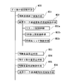
- FIG. 3 is a diagram showing an example of a control flow of the exhaust gas purification method according to the embodiment of the present invention.
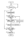
- FIG. 4 is a diagram showing details of the control step S20 of FIG.
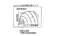
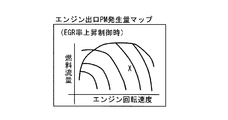
- FIG. 5 is a schematic diagram of an engine outlet PM generation amount map during normal combustion.
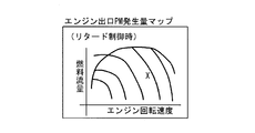
- FIG. 6 is a schematic diagram of an engine outlet PM generation amount map during the retard control.
- FIG. 7 is a schematic diagram of an engine outlet PM generation amount map during EGR rate increase control.
- FIG. 1 is a diagram showing a configuration of an exhaust gas purification system according to an embodiment of the present invention.
- FIG. 2 is a diagram showing the configuration of the control means of the exhaust gas purification system according to the embodiment of the present invention.
- FIG. 3 is a diagram showing an
- FIG. 8 is a schematic diagram of an engine outlet PM generation amount map during air-fuel ratio rich control.
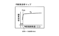
- FIG. 9 is a schematic diagram of a PM collection efficiency map.
- FIG. 10 is a diagram illustrating an example of a time series of the PM slip-through amount (Soot concentration) in the example and the conventional example.
- FIG. 11 is a diagram showing an example of a time series of the amount of PM slipping (Soot concentration at the DPF outlet) after forced regeneration of the DPF in the prior art.
- an exhaust gas purification system 1 of this embodiment includes an intake passage 12 connected to an intake manifold 11a of an engine body 11 of an engine (internal combustion engine) 10, and an exhaust passage 13 connected to an exhaust manifold 11b. And an EGR passage 14 connecting the exhaust manifold 11b and the intake manifold 11a.
- the intake passage 12 is provided with a compressor 15a, an intercooler 16 and an intake throttle (intake valve) 17 of a turbocharger (turbocharger) 15 in order from the upstream side. MAF), is supercharged by the compressor 15a, is further cooled by the intercooler 16, passes through the intake throttle 17 for adjusting the intake air amount, and is supplied to the intake manifold 11a.
- MAF intake valve
- MAF turbocharger
- the exhaust passage 13 is provided with a turbine 15b of the turbocharger 15, an in-exhaust passage fuel injection valve 18, and an exhaust gas purification device 19 in order from the upstream side.
- the exhaust gas purifying device 19 includes an upstream side oxidation catalyst (DOC: DeliesOxidation Catalyst) 19a and a downstream side DPF (Diesel Particulate Filter) 19b.
- DOC upstream side oxidation catalyst
- DPF Diesel Particulate Filter
- the fuel f is supplied into the exhaust gas G from the fuel injection valve 18 in the exhaust passage, the fuel f is oxidized by the oxidation catalyst 19a, and exhausted by the combustion heat of the fuel f.
- the temperature of the gas G and DPF 19b is raised, and the PM collected in the DPF 19b is reburned.
- the EGR passage 14 is provided with an EGR cooler 20 and an EGR valve 21 in order from the upstream side.
- EGR exhaust gas recirculation
- an EGR gas Ge that is a part of the exhaust gas G is introduced from the exhaust manifold 11b. After this EGR gas Ge is cooled by the EGR cooler 20, it passes through an EGR valve 21 that adjusts the amount of EGR gas and is supplied to the intake manifold 11a.
- the first exhaust gas temperature sensor 22 is provided upstream of the oxidation catalyst 19a
- the second exhaust gas temperature sensor 23 is provided between the oxidation catalyst 19a and the DPF 19b for measuring the differential pressure between the upstream side and the downstream side of the DPF 19b.
- a pressure sensor 24 is provided, and these detection signals are input to a control device 30 called an engine control unit (ECU) that controls the operation of the engine 10 and the exhaust gas purification system 1.
- the control device 30 receives detection signals from various sensors such as these sensors, other accelerator sensors, engine rotation sensors, cooling water sensors, and the like, and controls the intake throttle according to the operating conditions of the engine 10 and the state of the exhaust gas G. 17, controls the fuel injection valve 18 in the exhaust passage, the EGR valve 21 and the like.
- the DPF 19b disposed in the exhaust passage 13 of the exhaust gas purification system 1 collects PM contained in the exhaust gas G flowing through the exhaust passage 13, but the amount of PM collected by the DPF 19b. As the pressure increases, the pressure loss in the DPF 19b increases, resulting in deterioration of fuel consumption, or the amount of PM passing through the DPF 19b exceeding the PM collection limit increases. When it is detected that the collected amount exceeds the allowable amount or the differential pressure across the DPF 19b exceeds the allowable amount, a forced regeneration process for reburning the collected PM is performed to regenerate the DPF 19b.
- the control device 30 temporarily increases the amount of PM that passes through the DPF 19b immediately after the PM is reburned by the forced regeneration process of the PM in the DPF 19b.
- the surface cake filtration layer formation promotion control or the PM generation amount reduction control is re-formed, As a means for performing temporarily until it grows to some extent, it is configured to include a slip-through amount suppressing means M30.
- the slip-through amount suppression means M30 includes a PM reburning end detection means M31, a surface cake filtration layer formation promotion control means M32, a PM generation amount calculation means M33, a PM slip-through amount calculation means M34, a PM generation amount reduction control means M35, and a surface layer cake filtration. It has a layer re-forming detection means M36.
- This PM recombustion end detection means M31 is a means for detecting whether or not PM recombustion by the forced regeneration process of PM in the DPF 19b has been completed.
- the detection value ⁇ P of the differential pressure sensor 24 is set in advance. It is determined that PM reburning has ended when the value ⁇ Pc becomes smaller, or the PM concentration difference ⁇ Cpm before and after the DPF 19b and the PM collection efficiency ⁇ y calculated from this PM concentration difference ⁇ Cpm are set in advance. It is configured to determine that PM reburning has ended when it becomes smaller than ⁇ Cpm1 and ⁇ y1.
- the surface cake filtration layer formation promotion control means M32 increases the amount of PM (PM generation amount) in the exhaust gas G at the outlet of the engine 10 to increase the amount of PM passing through the DPF 19b (HC or the like as a main component).
- the surface cake filtration layer formation promoting control promotes the early formation and growth of the surface cake filtration layer on the wall surface of the DPF 19b immediately after the forced regeneration process. As a result, the PM slip-through amount Y is reduced, and the total amount of PM discharged into the atmosphere is reduced.
- the PM slipping amount Y before the surface cake filtration layer formation increases, but since the surface cake filtration layer is formed early, the total amount of PM discharged to the outside air is Reduced from the prior art.
- the surface cake filtration layer formation promotion control means M32 monitors the temperature of the DPF 19b, and retards the fuel injection timing in the cylinder fuel injection when the DPF temperature is equal to or lower than the preset temperature, and the EGR rate.
- EGR rate increase control means M32b that increases the PM generation amount due to the increase, and air-fuel ratio rich control that makes the air-fuel ratio rich in in-cylinder fuel injection when the DPF temperature is equal to or lower than a preset temperature while monitoring the temperature of the DPF 19b
- a means M32c is provided, and the PM amount (PM generation amount) X in the exhaust gas G at the outlet of the engine 10 is increased by performing any one of these means M32a, M32b, and M32c.
- the cylinder internal combustion temperature, the exhaust gas temperature, and the DPF temperature are decreased by the EGR rate increase,
- the formation of the surface cake filtration layer can be promoted by increasing the PM collection efficiency ⁇ y by the DPF 19b.
- air-fuel ratio rich control rich spike control or the like that makes the air-fuel ratio rich in in-cylinder fuel injection when the DPF temperature is equal to or lower than a preset temperature.
- the HC component in the exhaust gas G is increased at the DPF temperature so that the HC component in the exhaust gas G does not evaporate to become a gas phase state, and the HC in the liquid phase is added to the PM. Since the particle size can be increased by adhering and can be easily collected on the wall surface of the DPF 19b, the formation of the surface cake filtration layer can be promoted.
- the PM is made to be easily trapped on the surface layer of the wall surface of the DPF 19b. Since PM particles that are easily collected on the wall surface and easily form a surface cake filtration layer are considered to be wet (wet) PM having a relatively large particle diameter to which HC or the like is adsorbed, if the temperature drops while monitoring the DPF temperature The injection timing is temporarily retarded or the air-fuel ratio is made rich by a temporary rich spike. As a result, the exhaust gas component having a large amount of HC component is used, so that HC is attached to PM to increase the particle size, thereby facilitating collection on the wall surface of the DPF 19b.
- wet wet
- any means that facilitates the collection of PM on the front side of the wall surface of the DPF 19b and promotes the formation of the surface cake filtration layer is adopted as the surface cake filtration layer formation promotion control. it can.
- the PM generation amount calculation means M33 is a means for calculating the PM generation amount X generated at the outlet of the engine 10 immediately after the forced regeneration process of the DPF 19b, and the PM at the outlet of the engine 10, for example, the exhaust manifold 11b outlet, etc. Is generated in advance based on the engine operating state of the engine 10, a PM generation amount database is created, and the engine operating conditions immediately after the forced regeneration processing of the DPF 19b, for example, the engine speed and the engine torque ( Alternatively, the PM generation amount X is calculated from the in-cylinder fuel injection amount) with reference to the PM generation amount database. As a result, the PM generation amount can be accurately calculated based on a preset PM generation amount database.
- FIG. 5 shows an engine outlet PM generation amount map during normal combustion
- FIG. 6 shows an engine outlet PM generation amount map during retard control
- FIG. 7 shows an engine outlet PM generation amount during EGR rate increase control
- FIG. 8 shows an engine exit PM generation amount map during air-fuel ratio rich control.
- These engine exit PM generation amount maps can be measured by changing the engine speed (engine speed) and fuel flow rate (equivalent to engine torque and load) in a bench test, etc., and measuring the PM amount at the engine exit. And can be created. That is, a map of PM engine exit generation amount X is created experimentally.
- the PM slipping amount calculating means M34 is a means for calculating the PM amount passing through the DPF 19b, that is, the PM slipping amount Y.
- This PM collection efficiency ⁇ y is databased in advance, and the relationship between the amount of PM collected by the DPF 19b (PM collection amount) and the ratio of the PM collection amount Z to the PM generation amount X (PM collection efficiency) ⁇ y Is used, for example, as a PM collection efficiency map as shown in FIG.
- This PM collection efficiency map is also created based on the PM collection efficiency ⁇ Z in the DPF 19b by measuring the PM quantity before and after the DPF 19b and measuring the PM collection efficiency ⁇ y by a bench test or the like. That is, a correlation map between the PM accumulated collection amount ⁇ Z and the collection efficiency ⁇ y is created experimentally. This PM collection efficiency ⁇ y varies depending on the PM accumulated collection amount ⁇ Z.
- the PM generation amount reduction control means M35 determines that the PM generation amount X exceeds the preset PM generation allowable amount Xc during the temporary period until the surface cake filtration layer grows, or the PM slipping amount Y is This is a means for performing control for reducing the PM generation amount X from the engine 10 when the preset PM slip-through allowance Yc is exceeded.
- the PM generation amount reduction control employs the suppression control of the PM generation amount X due to the decrease in the EGR rate, and the suppression control of the PM generation amount X due to the decrease in the EGR rate causes the surface cake filtration layer to be re-formed and set in advance.
- the in-cylinder combustion temperature is raised, the PM generation amount X is decreased, and the PM slipping amount Y, which is the amount of PM that passes through the DPF 19b, is decreased. This reduces the total amount of PM discharged into the atmosphere.
- the emission amount of NOx is increased by the PM generation amount suppression control due to the decrease in the EGR rate, this can be dealt with by performing control such as increasing the reducing agent of the deNOx catalyst (for example, urea SCR catalyst) during this period.
- the surface cake filtration layer re-forming detection means M36 is means for detecting that the surface cake filtration layer has been re-formed and has grown to a preset level, and the PM slip-through amount calculation means M34 calculates the PM slip-through amount Y.
- the PM collection efficiency ⁇ y exceeds the preset PM collection return efficiency ⁇ yc, it is configured that the surface cake filtration layer is re-formed and detected to have grown to a preset level. Is done.
- the slipping amount suppression means M30 does not exceed the PM generation allowable amount Xc set in advance by the PM generation amount X calculated by the PM generation amount calculation means M33, and the PM calculated by the PM generation amount reduction control means M35.
- the surface cake filtration layer formation promotion control means M32 increases the retard control means M32a and the EGR rate according to the engine operating conditions, particularly the magnitude of the engine torque.
- Exceeds the preset allowable PM generation amount Xc, or the PM slippage amount Y calculated by the PM slippage amount calculation means M34 is equal to the PM slippage. If it exceeds the dropout tolerance Yc, configured to perform PM generation amount reduces controlled by the PM generation amount reduces control unit M35.
- the control flow of FIG. 3 is control for preventing deterioration of exhaust gas performance due to PM passing immediately after PM reburning of the DPF 19b.
- the engine 10 starts operation, and the exhaust gas purification system 1 controls the forced regeneration of the DPF 19b.
- the process is started, it is called from the upper control flow, starts, and after executing the steps of the control flow of FIGS.
- step S11 it is determined by the PM recombustion end detection means M31 whether or not PM reburning has ended.
- step S11 it is determined that PM re-combustion has ended when the detected value ⁇ P of the differential pressure sensor 24 becomes smaller than a preset set value ⁇ Pc, or the PM concentration difference ⁇ Cpm before and after the DPF 19b is It is determined that the PM reburning has ended when the PM collection efficiency ⁇ y calculated from the PM concentration difference ⁇ Cpm becomes smaller than preset values ⁇ Cpm1 and ⁇ y1.
- step S11 If it is determined in this step S11 that PM reburning has not ended (NO), after a preset first set time (time related to the determination interval in step S11) ⁇ t1 has elapsed, step S11 Return to, and wait until PM reburning is complete. If it is determined in this step S11 that PM reburning has ended (YES), the process proceeds to the next step S12. Note that the end of the forced regeneration process of the DPF that accompanies the end of PM reburning is performed in the upper control flow.
- a control start preparation work is performed.
- counting of the elapsed time ta of the PM slip-through amount suppression control is started, the PM cumulative collection amount ⁇ Z is reset to zero, and the PM cumulative collection amount which is an integrated value of the PM collection amount Z Start integration of ⁇ Z. That is, the integrated value of the amount of collected PM starts to be counted immediately after PM reburning.
- the PM generation amount calculation means M33 calculates the PM generation amount X generated in the engine operating state, and further calculates the PM slipping amount Y of the DPF 19b from the PM slipping amount calculation means M34.
- the PM collection efficiency ⁇ y is obtained by referring to the PM collection efficiency map data based on the PM accumulated collection amount ⁇ Z, and the PM collection efficiency ⁇ y and the PM generation amount X are used to calculate the PM.
- next step S13 it is determined whether or not the surface cake filtration layer formation promotion control is performed. That is, it is determined whether or not the control for early formation of the surface cake filtration layer can be performed. In other words, it is determined whether or not the PM generation amount X and the PM slip-through amount Y are within an allowable range. In this determination, the PM generation amount X calculated by the PM generation amount calculation means M33 does not exceed the preset PM generation allowable amount Xc (X ⁇ Xc), and is calculated by the PM slipping amount calculation means M34.
- the promotion control means M32 carries out surface cake filtration layer formation promotion control for a preset second set time (time related to the determination interval in step S13) ⁇ t2, and goes to step S14. In other words, the early formation of the surface cake filtration layer is controlled.
- the process proceeds to step S30, and the PM generation amount reduction control means M35 performs the PM generation amount reduction control for the second set time ⁇ t2, Go to step S14. That is, the EGR rate is temporarily lowered to reduce the PM slipping amount Y.
- the range in which this PM generation amount reduction control is performed is, for example, the “PM deterioration region” indicated by the lower left hatching in the PM generation amount map during normal operation shown in FIG.
- step S13 the control is started. If the same control as the previous control is selected, the control is continued as it is, and a control different from the previous control is selected. In this case, the control is switched to the newly selected control.
- step S21 it is determined in step S21 whether or not the engine torque T of the engine 10 is lower than a preset first set value T1. If it is low, it is determined that the vehicle is in the low load range, and the process goes to step S23, where the retard control by the retard control means M32a is set in advance to the third set time (second set time, the determination interval of steps S21 and S20) For a period of time ⁇ t3, and goes to step S14 of the control flow of FIG. That is, while monitoring the temperature of the DPF 19b, the HC component in the exhaust gas G is increased by temporarily retarding the injection timing of the in-cylinder fuel injection after the temperature drops.
- step S21 if the engine torque T is greater than or equal to the first set value T1, the process goes to step S22 to determine whether or not the engine torque T is lower than the preset second set value T2. If it is low, it is determined that the vehicle is in the middle load range, the process goes to step S24, EGR rate increase control by the EGR rate increase control means M32b is performed for the third set time ⁇ t3, and the process goes to step S14 in the control flow of FIG. . That is, the EGR rate is increased to slightly worsen the smoke and promote the growth of the surface cake filtration layer.
- step S22 If it is determined in step S22 that the engine torque T is greater than or equal to the second set value T2, it is determined that the engine torque T is in the high load range, the process proceeds to step S25, and the air-fuel ratio rich control by the air-fuel ratio rich control means M32c is performed for the third set time ⁇ t3. And go to step S14 in the control flow of FIG. That is, while monitoring the temperature of the DPF 19b, the HC component in the exhaust gas G is increased by temporarily making the air-fuel ratio rich with a rich spike after the temperature drop.
- control when any one is selected, other control is stopped and it does not implement simultaneously. Therefore, if a new control is selected in the determinations in steps S21 and S22, the control is started. If the same control as the previous control is selected, the control is continued as it is, and a control different from the previous control is selected. If so, the control is switched to the newly selected control.
- step S14 of the control flow of FIG. 3 the PM generation amount X during the execution of step S20 or step S30, in other words, the PM generation generated by the surface cake filtration layer formation promotion control is performed by the PM generation amount calculation means M33.
- An amount X or a PM generation amount X generated by the PM generation amount reduction control is calculated.
- the PM collection efficiency calculating unit M34 refers to the PM collection efficiency map data based on the PM accumulated collection amount ⁇ Z, which is an integrated value of the PM collection amount Z from the start of counting the elapsed time ta, and collects PM.
- next step S15 it is determined whether or not the surface cake filtration layer formation promotion control is finished. This determination is made based on whether the elapsed time ta has passed a preset set time tc and whether the surface cake filtration layer has been re-formed and grown to a preset level.
- This set time tc is determined in advance so that the differential pressure across the DPF 19b is determined in advance so that the surface cake filtration layer formation promotion control or PM generation amount reduction control for suppressing the PM slip-through amount is limited to only a short time after PM reburning. Is set to be between 3 minutes and 7 minutes (preferably about 5 minutes).
- step S15 the determination that the elapsed time ta has passed the preset time tc (t ⁇ tc), or the surface cake filtration layer re-forming detection means M36, the surface cake filtration layer is re-formed, If there is any of the determination that the PM collection efficiency ⁇ y has exceeded the preset PM collection return efficiency ⁇ yc, the surface cake filtration layer formation promotion control is determined to have been completed. YES), the process proceeds to the control end operation in step S16.
- step S16 the elapsed time ta is reset, and the surface cake filtration layer formation promotion control or PM generation amount reduction control that has been performed until reaching this step S16 is ended.
- the normal operation control is performed to perform EGR control and in-cylinder fuel injection timing control.
- step S16 If the operation of the engine 10 is stopped in the middle of the control, the control jumps to step S16 even in the middle of the control due to the interruption, the control end work is finished, the control flow is returned to the upper control flow, and the upper control flow. At the end, the control flow of FIGS. 3 and 4 also ends.
- the amount of PM passing through the DPF 19b (PM slipping amount) Y temporarily increases, and the amount of PM discharged into the atmosphere temporarily increases.
- the surface cake filtration layer formation promotion control that increases the PM generation amount X from the normal operation immediately after the PM reburning in the forced regeneration process
- the PM generation amount reduction control that increases the PM generation amount X from the normal operation
- the PM generation amount increase control due to the EGR rate increase the retard control that retards the fuel injection timing in the cylinder fuel injection, or the cylinder fuel Any one of air-fuel ratio rich control that makes the air-fuel ratio rich in injection can be performed.
- the PM generation amount X is increased by lowering the in-cylinder combustion temperature, the exhaust gas temperature, and the DPF temperature by increasing the EGR rate.
- the formation of the surface cake filtration layer can be promoted by increasing the PM collection efficiency ⁇ y by the DPF 19b.
- HC component hydrocarbon component
- the PM generation amount suppression control by the EGR rate reduction can be performed as the PM generation amount reduction control. Therefore, by controlling the PM generation amount by reducing the EGR rate, the in-cylinder combustion temperature is raised, the PM generation amount is decreased, and the PM slipping amount Y that passes through the DPF 19b can be reduced. Thereby, PM slip-through amount Y can be suppressed until the surface cake filtration layer is formed to some extent.
- the retard control when the engine torque T of the engine 10 is lower than the first preset value T1, the retard control is performed, and the engine torque T is set to the first preset value T1.
- the EGR rate increase control can be performed.
- the air-fuel ratio rich control can be performed.
- the optimal surface cake filter layer formation promotion control can be selected according to the engine torque (engine output) T of the engine 10, the surface cake filter layer can be efficiently produced while reducing adverse effects on the engine torque T and exhaust gas performance. Formation can be promoted, and the total amount of PM discharged into the atmosphere can be reduced.
- the PM generation amount reduction control can be performed when the PM slipping amount Y, which is the amount of PM passing through the DPF 19b, exceeds a preset PM slipping allowance amount Yc. Therefore, since the PM generation amount reduction control is performed based on the PM generation amount X or the PM slipping amount Y, the total amount of PM discharged into the atmosphere can be reliably reduced.
- FIG. 10 is a diagram showing an example of a time series of the PM slip-through amount Y in the embodiment of the present invention and the conventional example of the prior art.
- the Soot concentration (PM slipping amount) at the DPF outlet of the “Example” in which the formation of the cake layer was promoted and the prior art The soot concentration at the outlet of the DPF is reduced to about one third of that of the conventional example, and in the example, the PM slip-through amount Y immediately after the forced regeneration processing of the DPF 19b is reduced to the outside air. It can be seen that the total amount of PM emissions can be reduced.
- the PM recombustion of the forced regeneration process for the DPF 19b in the exhaust gas purification system 1 in which the DPF 19b is disposed in the exhaust passage 13 of the engine 10, the PM recombustion of the forced regeneration process for the DPF 19b.
- the surface cake filtration layer on the wall surface of the DPF 19b is temporarily controlled by the surface cake filtration layer formation promotion control that increases the PM generation amount X against the PM slipping (blow-off) phenomenon in which the PM slipping amount Y temporarily increases.
- the PM slipping amount immediately after the PM recombustion in the forced regeneration processing for the DPF in the exhaust gas purification system in which the DPF is disposed in the exhaust passage of the internal combustion engine, the PM slipping amount immediately after the PM recombustion in the forced regeneration processing for the DPF.
- the total amount of PM discharged into the atmosphere immediately after PM recombustion in the DPF forced regeneration process can be reduced. Since the total emission amount can be reduced, it can be used for an internal combustion engine mounted on an automobile or the like.
Landscapes
- Engineering & Computer Science (AREA)
- Chemical & Material Sciences (AREA)
- Combustion & Propulsion (AREA)
- Mechanical Engineering (AREA)
- General Engineering & Computer Science (AREA)
- Chemical Kinetics & Catalysis (AREA)
- Processes For Solid Components From Exhaust (AREA)
- Electrical Control Of Air Or Fuel Supplied To Internal-Combustion Engine (AREA)
- Combined Controls Of Internal Combustion Engines (AREA)
- Output Control And Ontrol Of Special Type Engine (AREA)
Abstract
内燃機関10の排気通路13にDPF19bを配設している排気ガス浄化システム1において、前記DPF19bに対する強制再生処理の直後に、表層ケーク濾過層形成促進制御、又は、PM発生量軽減制御を一時的に行う。これにより、内燃機関の排気通路にDPFを配設している排気ガス浄化システムにおいて、DPFに対する強制再生処理におけるPM再燃焼直後のPMすり抜け量が一時的に増加するというPMすり抜け現象に対して、DPFの強制再生処理でのPM再燃焼直後の大気中へのPMの排出総量を軽減して、大気中へのPMの排出総量を減少する排気ガス浄化システム及び排気ガス浄化方法を提供する。
Description
本発明は、内燃機関の排気通路にDPFを配設している排気ガス浄化システムにおいて、DPFに対する強制再生処理におけるPM再燃焼直後のPMすり抜けを抑制して大気中へのPMの排出総量を軽減することができる排気ガス浄化システム及び排気ガス浄化方法に関する。
内燃機関の排気通路より車外に排出される排気ガス中のPM(粒子状物質)を除去するために、内燃機関の排気通路にPMを捕集するDPF(ディーゼル・パティキュレート・フィルタ)を配設している排気ガス浄化システムが用いられている。このDPFではPMの捕集量の増加に伴い、DPFにおける圧力損失が増加して燃費の悪化が生じたり、PMの捕集限界を超えてDPFをすり抜けるPM量が増加して排気性能が低下したりするため、定期的にDPFを昇温して、捕集されたPMを再燃焼する強制再生処理を行って、大気中へ排出されるPMの量を減少している。このDPFの採用により、大気中に排出されるPMの量を1/100程度のレベルにしている。
しかしながら、図11に示すように、DPFにおいては、DPFの強制再生処理でPMが再燃焼した後に、PMがDPFを通過してしまう「PMすり抜け(煤ブレークスルー)」により、大気中へのPM排出量が一時的に増加する(図11でDPF出口のSoot濃度が上昇する)という現象が発生するという問題がある。この現象は次のようにして発生すると考えられている。
例えば、ウォ-ルフロータイプのDPFにおいては、PMはセル間を仕切る壁面を通過する際に壁面に捕集されるが、大きめの微粒子のPMは壁面を通過しないで壁面の前側(上流側)に付着して表層ケーク濾過層を生成する。この表層ケーク濾過層の生成により圧力損失はある程度上昇するが、同時に、PMに対する捕集効率も向上する。しかし、この表層ケーク濾過層は、DPFの強制再生処理におけるPMの再燃焼により燃焼して無くなるので、PMの捕集効率が一時的に低下するPMすり抜け(ブローオフ)が発生する。その結果、PMがDPFで捕集されずにDPFをすり抜けてしまうことになり、一時的に大気中へのPM排出量が増加する。
なお、その後、強制再生処理で昇温したDPFの温度が低下してくると、再び、DPFにPMが捕集されて、壁面の前側に表層ケーク濾過層が再形成され、その成長に伴ってPMの捕集効率が上昇するので、PMすり抜け量が減少し、大気中へのPM排出量も減少する。
このPMすり抜けによる大気中へのPM排出量の一時的な増加によるPM浄化の悪化度合いは目に見える程では無いが、排気ガス性能の認証時に申請する劣化係数であるK-ファクターの悪化等を招くので、これへの対策が必要となる。
この対策の一つとして、本発明者は、例えば、日本出願の特開2011-149357号公報に記載されているように、内燃機関の排気ガス流路にDPFを設けた排気ガス装置で、DPF再生直後のPM捕集効率の低下(ブローオフ)によるPMがDPFをすり抜ける煤ブレークスルーを低減するために、DPFの強制再生で行うポスト噴射を、DPFの下流で検出されるPM濃度が所定値以上になり、DPFのブローオフが発生した時点でポスト噴射を禁止して、DPFの強制再生を終了させて、これにより、ポスト噴射に起因するPMの大気中への排出量の一時的な増加の抑止を図った、DPF再生装置を提案している。
このDPF再生装置では、DPFのブローオフの発生時とDPFの強制再生処理のポスト噴射の終了時を一致させることで、DPFの強制再生処理のために行うポスト噴射に起因して発生するPMがPMの再燃焼直後のブローオフ時に大気中へ排出されるのを防止して、大気中へのPM排出量の増加の抑止を図っている。
本発明者は、このDPF装置で提案した、DPFの強制再生処理で行うポスト噴射を終了する時期をPMの再燃焼終了時に合わせることで、PMすり抜け現象発生時のポスト噴射によって発生するPM量をなくすという消極的な対処方法だけでなく、さらに、DPFの強制再生処理のPM再燃焼終了後における、大気中へのPM排出量の増加の抑止を積極的に図ることが必要であるとの知見を得て、本発明者は本発明に想到した。
本発明は、上記のことを鑑みてなされたものであり、その目的は、内燃機関の排気通路にDPFを配設している排気ガス浄化システムにおいて、DPFに対する強制再生処理におけるPM再燃焼直後のPMすり抜け量が一時的に増加するというPMすり抜け現象に対して、DPFの強制再生処理でのPM再燃焼直後の大気中へのPMの排出総量を軽減することができて、大気中へのPMの排出総量を減少することができる排気ガス浄化システム及び排気ガス浄化方法を提供することにある。
上記の目的を達成するための本発明による排気ガス浄化システムは、内燃機関の排気通路にDPFを配設している排気ガス浄化システムにおいて、前記DPFに対する強制再生処理のPM再燃焼直後に、表層ケーク濾過層形成促進制御、又は、PM発生量軽減制御を一時的に行うように構成される。
なお、この一時的とは、大気中へのPM排出量が一時的に増加する現象(ブローオフ)が発生している期間に関係する間であり、予め設定した時間(例えば5分間等)の間、PM累積捕集量が予め設定した量以上になるような値になるまでの間、PM捕集効率が予め設定した率以上になるまでの間、PMすり抜け量が予め設定した量以下になるまでの間、PMすり抜け率が予め設定した値以下になるまでの間などをこの一時的の期間として採用することができる。
この構成によれば、DPFにおけるPMの強制再生処理によるPMの再燃焼の直後に、DPFを通過するPMの量が一時的に増加して、大気中へのPM排出量が一時的に増加する現象(ブローオフ)に対して、この現象が発生している期間内で、通常運転時よりPM発生量を増加させる表層ケーク濾過層形成促進制御により、強制再生処理のPM再燃焼直後のDPFの壁面に対して、表層ケーク濾過層の早期形成と成長を促進させることで、PMすり抜け量を減少させ、大気中へのPMの排出総量を軽減することができる。
又は、通常運転時よりPM発生量を減少させるPM発生量軽減制御により、表層ケーク濾過層が成長するまでの一時的な期間の間、内燃機関からのPM発生量を軽減することにより、DPFに流入するPM量を減少して、DPFすり抜け量を減少させ、大気中へのPMの排出総量を軽減することができる。
上記の排気ガス浄化システムにおいて、前記表層ケーク濾過層形成促進制御が、EGR率上昇によるPM発生量の増加制御、又は、シリンダ内燃料噴射において燃料の噴射タイミングをリタードさせるリタード制御、又は、シリンダ内燃料噴射において空燃比をリッチとする空燃比リッチ制御の何れかの制御であるように構成すると、次のような効果を奏することができる。
つまり、この構成にすると、EGR率上昇によるPM発生量の増加制御の場合には、EGR率上昇により、シリンダ内燃焼温度を低下させて、Soot生成量の僅かな増加と、HC濃度を増加させてSoot粒子へ吸着させ、粒子径を拡大することにより、表層ケーク濾過層の形成を促進することができる。
また、シリンダ内燃料噴射において燃料の噴射タイミングをリタードさせるリタード制御と、シリンダ内燃料噴射において空燃比をリッチとする空燃比リッチ制御(リッチスパイク制御等)では、これらの制御により排気ガス中のHC成分(炭化水素成分)を多くして、PMにHCを付着させて粒子径を大きくし、DPFの壁面に捕集され易くすることができるので、これにより、表層ケーク濾過層の形成を促進することができる。
なお、リタード制御と空燃比リッチ制御では、表層ケーク濾過層の形成を促進する効果を高めるため、DPF温度をモニターして、HCが蒸発して気相状態にならずに、PMに付着し易い液相状態のままDPFの壁面に付着できる温度のときにこれらの制御を行うように構成することがより好ましい。
上記の排気ガス浄化システムにおいて、前記PM発生量軽減制御が、EGR率減少によるPM発生量の抑制制御であるように構成すると、このEGR率減少によるPM発生量の抑制制御により、シリンダ内燃焼温度を上昇させて、PM発生量を減少し、DPFをすり抜けるPMの量を減少できる。これにより、表層ケーク濾過層がある程度形成されるまで、PMすり抜け量を抑制できる。
上記の排気ガス浄化システムで、前記表層ケーク濾過層形成促進制御において、前記内燃機関のエンジントルクが予め設定した第1設定値より低い場合は前記リタード制御を行い、前記エンジントルクが前記第1設定値以上でかつ予め設定した第2設定値より低い場合は前記EGR率上昇制御を行い、前記エンジントルクが前記第2設定値以上である場合は前記空燃比リッチ制御を行うよう構成する。この構成にすると、内燃機関のエンジントルク(エンジン出力)に応じて、最適な表層ケーク濾過層形成促進制御を選択できるので、エンジントルクや排ガス性能への悪影響を少なくしながら、効率よく表層ケーク濾過層の形成を促進でき、大気中へのPMの排出総量を軽減できる。
上記の排気ガス浄化システムにおいて、前記DPFの強制再生処理のPM再燃焼直後で、前記内燃機関で発生するPMの発生量であるPM発生量が、予め設定されたPM発生許容量を超えた場合、又は、前記DPFを通過するPMの量であるPMすり抜け量が、予め設定されたPMすり抜け許容量を超えた場合に、前記PM発生量軽減制御を行うように構成する。この構成にすると、PM発生量又はPMすり抜け量に基づいてPM発生量軽減制御を行うので、確実に大気中へのPMの排出総量を軽減できる。
このDPFの強制再生処理のPM再燃焼直後の内燃機関で発生するPMの発生量であるPM発生量は、前記内燃機関のエンジン運転状態をベースに予めデータ化してPM発生量データベースを作成しておき、前記DPFの強制再生処理の直後のエンジン運転状態から前記PM発生量データベースを参照して算出することが好ましい。この構成にすると、予め設定されたPM発生量データベースを基にPM発生量を精度よく算出できる。
また、このDPFの強制再生処理のPM再燃焼直後の前記DPFを通過するPMの量であるPMすり抜け量は、PM再燃焼直後からのPM捕集効率をPM累積捕集量ベースに予めデータ化してPM捕集効率データベースを作成しておき、前記DPFの強制再生処理の直後のエンジン運転状態から前記PM発生量データベースを参照して算出されたPM発生量と、PM捕集効率(直前のPM累積捕集量から導かれる)から算出されたPM捕集量と、このPM捕集量の積算値であるPM累積捕集量を算出し、このPM発生量からPM捕集量を引き算してPMすり抜け量を算出することが好ましい。この構成にすると、予め設定されたPM発生量データベース、PM捕集効率データベースを基にPMすり抜け量を精度よく算出できる。
そして、上記の目的を達成するための本発明の排気ガス浄化方法は、内燃機関の排気ガスをDPFで浄化する排気ガス浄化方法において、前記DPFに対する強制再生処理のPM再燃焼直後に、表層ケーク濾過層形成促進制御、又は、PM発生量軽減制御を一時的に行うことを特徴とする方法である。
上記の排気ガス浄化方法において、前記表層ケーク濾過層形成促進制御として、EGR率上昇によるPM発生量の増加制御、又は、シリンダ内燃料噴射において燃料の噴射タイミングをリタードさせるリタード制御、又は、シリンダ内燃料噴射において空燃比をリッチとする空燃比リッチ制御の何れかの制御を行う。
また、上記の排気ガス浄化方法において、前記PM発生量軽減制御として、EGR率減少によるPM発生量の抑制制御を行う。
更に、上記の排気ガス浄化方法で、前記表層ケーク濾過層形成促進制御において、前記内燃機関のエンジントルクが予め設定した第1設定値より低い場合は前記リタード制御を行い、前記エンジントルクが前記第1設定値以上でかつ予め設定した第2設定値より低い場合は前記EGR率上昇制御を行い、前記エンジントルクが前記第2設定値以上である場合は前記空燃比リッチ制御を行う。
また、上記の排気ガス浄化方法において、前記DPFの強制再生処理のPM再燃焼直後で、前記内燃機関で発生するPMの発生量であるPM発生量が、予め設定されたPM発生許容量を超えた場合、又は、前記DPFを通過するPMの量であるPMすり抜け量が、予め設定されたPMすり抜け許容量を超えた場合に、前記PM発生量軽減制御を行う。
これらの排気ガス浄化方法によれば、上記の排気ガス浄化システムと同様な効果を奏することができる。
本発明の排気ガス浄化システム及び排気ガス浄化方法によれば、内燃機関の排気通路にDPFを配設している排気ガス浄化システムにおいて、DPFに対する強制再生処理のPM再燃焼直後に、PMすり抜け量が一時的に増加するPMすり抜け(ブローオフ)現象に対して、PM発生量を増加する表層ケーク濾過層形成促進制御で、一時的にDPFの壁面における表層ケーク濾過層の早期再形成と成長を促進させることにより、又は、PM発生量を減少するPM発生量軽減制御で、表層ケーク濾過層が再形成されて成長するまでの一時的な期間の間、内燃機関からのPM発生量を軽減して、DPFに流入するPM量を減少することにより、DPFの強制再生処理でのPM再燃焼直後の大気中へのPMの排出総量を軽減することができて、大気中へのPMの排出総量を減少することができる。
以下、本発明に係る実施の形態の排気ガス浄化システム及び排気ガス浄化方法について図面を参照しながら説明する。図1に示すように、この実施の形態の排気ガス浄化システム1は、エンジン(内燃機関)10のエンジン本体11の吸気マニホールド11aに接続する吸気通路12と、排気マニホールド11bに接続する排気通路13と、排気マニホールド11bと吸気マニホールド11aを接続するEGR通路14を備えて構成されている。
吸気通路12には、上流側から順に、ターボ式過給機(ターボチャージャ)15のコンプレッサ15aとインタークーラー16と吸気スロットル(吸気弁)17が設けられ、吸入空気Aはエアクリーナーや吸気量センサ(MAF)を通過して、コンプレッサ15aにより過給されて、さらに、インタークーラー16により冷却され、吸入空気量を調整する吸気スロットル17を通過して、吸気マニホールド11aに供給される。
また、排気通路13には、上流側から順に、ターボ式過給機15のタービン15b、排気通路内燃料噴射弁18、排気ガス浄化装置19が設けられている。この排気ガス浄化装置19は、上流側の酸化触媒(DOC:Diesel Oxidation Catalyst)19aと下流側のDPF(Diesel Particulate Filter:ディーゼル・パティキュレート・フィルタ)19bとから構成されており、排気ガスG中のPM(Particulate Matter:粒子状物質)はこのDPF19bで捕集され、PM捕集量が増加すると、DPF19bの強制再生処理を行う。このDPF19bの強制再生処理におけるPMの再燃焼では、排気通路内燃料噴射弁18から燃料fが排気ガスG中に供給され、この燃料fが酸化触媒19aで酸化され、燃料fの燃焼熱により排気ガスG及びDPF19bが昇温され、DPF19bに捕集されているPMが再燃焼処理される。
また、EGR通路14には、上流側から順にEGRクーラー20とEGR弁21が設けられ、EGR(排気再循環)時には、排気マニホールド11bから排気ガスGの一部であるEGRガスGeを導入し、このEGRガスGeはEGRクーラー20で冷却された後、EGRガス量を調整するEGR弁21を通過して吸気マニホールド11aに供給される。
また、酸化触媒19aの上流側に第1排気ガス温度センサ22を、酸化触媒19aとDPF19bの間に第2排気ガス温度センサ23を、DPF19bの上流側と下流側の差圧の測定用として差圧センサ24をそれぞれ設け、これらの検出信号をエンジン10の運転と排気ガス浄化システム1を制御するエンジンコントロールユニット(ECU)と呼ばれる制御装置30に入力する。この制御装置30は、これらのセンサやその他のアクセルセンサ、エンジン回転センサ、冷却水センサ等の各種のセンサの検出信号を入力し、エンジン10の運転条件や排気ガスGの状態などにより、吸気スロットル17、排気通路内燃料噴射弁18、EGR弁21等を制御する。
そして、排気ガス浄化システム1の排気通路13に配置されているDPF19bは、排気通路13を流れる排気ガスGに含まれているPMを捕集するが、DPF19bで捕集されるPMの捕集量の増加に伴い、DPF19bにおける圧力損失が増加して燃費の悪化等が生じたり、PMの捕集限界を超えてPMがDPF19bをすり抜ける量が増加したりするため、定期的に、または、PM捕集量が許容量を超えたり、DPF19bの前後差圧が許容量を超えたりしたことを検知した場合に、捕集されたPMを再燃焼する強制再生処理を行い、DPF19bを再生している。
しかしながら、DPF19bの強制再生処理で、捕集されたPMが再燃焼された直後では、DPF19bの排気ガスGが通過する壁面の前側に形成されていた、HC等、粒子径の大きいPMの集合体である表層ケーク濾過層が消失してしまうので、一時的にDPF19bをPMがすり抜けるブローオフ現象が発生する。
そこで、図2に示すように、本発明における制御装置30は、DPF19bにおけるPMの強制再生処理によるPMの再燃焼直後に、DPF19bを通過するPMの量が一時的に増加して、大気中へのPM排出量が一時的に増加する現象に対して、DPF19bに対する強制再生処理の直後に、表層ケーク濾過層形成促進制御、又は、PM発生量軽減制御を、表層ケーク濾過層が再形成され、ある程度成長するまでの間、一時的に行うための手段として、すり抜け量抑制手段M30を有して構成される。すり抜け量抑制手段M30は、PM再燃焼終了検知手段M31、表層ケーク濾過層形成促進制御手段M32、PM発生量算出手段M33、PMすり抜け量算出手段M34、PM発生量軽減制御手段M35、表層ケーク濾過層再形成検知手段M36を有して構成される。
このPM再燃焼終了検知手段M31は、DPF19bにおけるPMの強制再生処理によるPMの再燃焼が終了した否かを検出する手段であり、例えば、差圧センサ24の検出値ΔPが予め設定された設定値ΔPcより小さくなった時点でPM再燃焼が終了したと判定したり、あるいは、DPF19bの前後のPM濃度差ΔCpmやこのPM濃度差ΔCpmから算出されるPM捕集効率ηyが予め設定された値ΔCpm1、ηy1より小さくなった時点でPM再燃焼が終了したと判定したりするように構成される。
また、表層ケーク濾過層形成促進制御手段M32は、エンジン10の出口における排気ガスG中のPMの量(PM発生量)を増加させることで、DPF19bを通過するPMの量(HC等が主成分)を増加させる制御を行う手段であり、この表層ケーク濾過層形成促進制御により、強制再生処理の直後のDPF19bの壁面に対して、表層ケーク濾過層の早期形成と成長を促進させる。これにより、PMすり抜け量Yを減少させ、大気中へのPMの排出総量を軽減する。なお、表層ケーク濾過層形成促進制御を行うことで、表層ケーク濾過層形成前におけるPMすり抜け量Yは増加するが、表層ケーク濾過層が早期に形成されるため、外気へのPMの排出総量は従来技術よりも減少する。
この表層ケーク濾過層形成促進制御手段M32は、DPF19bの温度をモニターしながら、DPF温度が予め設定した温度以下のときにはシリンダ内燃料噴射において燃料の噴射タイミングをリタードさせるリタード制御手段M32aと、EGR率上昇によるPM発生量の増加を行うEGR率上昇制御手段M32bと、DPF19bの温度をモニターしながら、DPF温度が予め設定した温度以下のときにはシリンダ内燃料噴射において空燃比をリッチとする空燃比リッチ制御手段M32cを備えて構成され、これらの手段M32a、M32b,M32cのいずれかを行うことで、エンジン10の出口における排気ガスG中のPMの量(PM発生量)Xを増加させる。
リタード制御手段M32aにおける、DPF19bの温度をモニターしながら、DPF温度が予め設定した温度以下のときにはシリンダ内燃料噴射において燃料の噴射タイミングをリタードさせるリタード制御を行い、排気ガスG中のHC成分が蒸発して気相状態にならないようなDPF温度で、排気ガスG中のHC成分を多くして、PMに液相状態のHCを付着させて粒子径を大きくし、DPF19bの壁面に捕集され易くすることができるので、これにより、表層ケーク濾過層の形成を促進することができる。
また、EGR率上昇制御手段M32bにおける、EGR率上昇によるPM発生量Xの増加制御の場合には、EGR率上昇により、シリンダ内のシリンダ内燃焼温度と排気ガス温度とDPF温度を低下させて、PM発生量Xを増加させることにより、DPF19bによるPM捕集効率ηyの増加により、表層ケーク濾過層の形成を促進することができる。
また、空燃比リッチ制御手段M32cにおける、DPF19bの温度をモニターしながら、DPF温度が予め設定した温度以下のときにはシリンダ内燃料噴射において空燃比をリッチとする空燃比リッチ制御(リッチスパイク制御等)を行い、リタード制御と同様に、排気ガスG中のHC成分が蒸発して気相状態にならないようなDPF温度で、排気ガスG中のHC成分を多くして、PMに液相状態のHCを付着させて粒子径を大きくし、DPF19bの壁面に捕集され易くすることができるので、これにより、表層ケーク濾過層の形成を促進することができる。
つまり、PMを更にDPF19bの壁面の表層に溜まり易い煤にする。壁面に捕集され表層ケーク濾過層を作り易いPM粒子は、HC等が吸着した粒子径の比較的大きい湿った(ウエットな)PMと考えられるので、DPF温度をモニターしながら、温度が低下したら、一時的に噴射タイミングをリタードしたり、一時的なリッチスパイクで空燃比をリッチとする。これらにより、HC成分の多い排ガス成分になるようにして、PMにHCを付着させて粒子径を大きくして、DPF19bの壁面に捕集し易くする。
なお、上記手段M32a、M32b、M32c以外にも、DPF19bの壁面前側にPMを捕集し易くして、表層ケーク濾過層の形成を促進できる手段であれば、表層ケーク濾過層形成促進制御として採用できる。
そして、これらの表層ケーク濾過層形成促進制御において、エンジン10のエンジントルクTが予め設定した第1設定値T1より低く、EGR率に対してスモーク濃度の変化の鈍感な低負荷域の場合は、リタード制御手段M32aによるリタード制御を行い、エンジントルクTが第1設定値T1以上でかつ予め設定した第2設定値T2より低く、EGR率に対してスモーク濃度の変化の敏感な中負荷域の場合はEGR率上昇制御手段M32bによるEGR率上昇制御を行い、エンジントルクTが第2設定値T2以上であり、シリンダ内燃料噴射のタイミングやEGR率を変化させるとエンジン10の動力性能に影響が出易い高負荷域の場合は空燃比リッチ制御手段M32cによる空燃比リッチ制御を行う。
この構成にすると、エンジン10のエンジントルク(エンジン出力)に応じて、最適な表層ケーク濾過層形成促進制御のための手段M32a、M32b、M32cのいずれかを選択できるので、エンジントルクTや排ガス性能への悪影響を少なくしながら、効率よく表層ケーク濾過層の形成を促進でき、大気中へのPMの排出総量を軽減できる。
また、PM発生量算出手段M33は、DPF19bの強制再生処理の直後のエンジン10の出口で発生するPM発生量Xを算出する手段であり、エンジン10の出口、例えば、排気マニホールド11b出口等のPMの発生量Xをエンジン10のエンジン運転状態をベースに予めデータ化して、PM発生量データベースを作成しておき、DPF19bの強制再生処理の直後のエンジン運転条件、例えば、エンジン回転速度やエンジントルク(又はシリンダ内燃料噴射量)から、PM発生量データベースを参照して、PM発生量Xを算出する。これにより、予め設定されたPM発生量データベースを基にPM発生量を精度よく算出できるようになる。
このデータベースの例として、図5に通常燃焼時のエンジン出口PM発生量マップを、図6にリタード制御時のエンジン出口PM発生量マップを、図7にEGR率上昇制御時のエンジン出口PM発生量マップを、図8に空燃比リッチ制御時のエンジン出口PM発生量マップを、それぞれ示す。これらのエンジン出口PM発生量マップは、ベンチテストなどで、エンジン回転速度(エンジン回転数)と、燃料流量(エンジントルク、負荷に相当)を変更して、エンジン出口でのPM量を測定するなどして、作成することができる。つまり、実験的にPMのエンジン出口発生量Xのマップを作成しておく。
また、PMすり抜け量算出手段M34は、DPF19bをすり抜けるPM量、即ち、PMすり抜け量Yを算出する手段であり、このPMすり抜け量Yの算出に際しては、PM発生量XにPM捕集効率ηyを乗じてPMすり抜け量Y(=X×ηy)を算出する。このPM捕集効率ηyは、予めデータベース化して、DPF19bで捕集されるPMの量(PM捕集量)とPM発生量Xに対するPM捕集量Zの割合(PM捕集効率)ηyの関係を作成し、例えば、図9に示すようなPM捕集効率マップにして用いる。このPM捕集効率マップも、ベンチテスト等で、DPF19bの前後のPM量を測定してPM捕集効率ηyを測定し、DPF19bにおけるPM累積捕集量ΣZをベースに作成する。つまり、実験的にPM累積捕集量ΣZと捕集効率ηyの相関マップを作成しておく。このPM捕集効率ηyは、PM累積捕集量ΣZにより変化する。
PM発生量軽減制御手段M35は、表層ケーク濾過層が成長するまでの一時的な期間の間、PM発生量Xが予め設定されたPM発生許容量Xcを超えるか、あるいは、PMすり抜け量Yが予め設定されたPMすり抜け許容量Ycを超えるかした場合に、エンジン10からのPM発生量Xを軽減する制御を行う手段である。このPM発生量軽減制御には、EGR率減少によるPM発生量Xの抑制制御を採用し、このEGR率減少によるPM発生量Xの抑制制御により、表層ケーク濾過層が再形成され、予め設定された程度成長するまでの一時的な期間の間、シリンダ内燃焼温度を上昇させて、PM発生量Xを減少し、DPF19bをすり抜けるPMの量であるPMすり抜け量Yを減少する。これにより、大気中へのPMの排出総量を軽減する。なお、このEGR率減少によるPM発生量抑制制御により、NOxの排出量が増加するが、この間はdeNOx触媒(例えば尿素SCR触媒)の還元剤を増加させる等の制御を行うことで、対処できる。
表層ケーク濾過層再形成検知手段M36は、表層ケーク濾過層が再形成され、予め設定された程度まで成長したことを検知する手段であり、PMすり抜け量算出手段M34でPMすり抜け量Yを算出する際の、PM捕集効率ηyが予め設定したPM捕集復帰効率ηycを超えた時点で、表層ケーク濾過層が再形成され、予め設定された程度まで成長したことを検知したとするように構成される。
そして、すり抜け量抑制手段M30は、PM発生量算出手段M33で算出したPM発生量Xが、予め設定されたPM発生許容量Xcを超えず、かつ、PM発生量軽減制御手段M35で算出したPMすり抜け量YがPMすり抜け許容量Ycを超えない場合に、表層ケーク濾過層形成促進制御手段M32で、エンジンの運転条件、特にエンジントルクの大きさに応じて、リタード制御手段M32aと、EGR率上昇制御手段M32bと、空燃比リッチ制御手段M32cのいずれかを選択しては、PM発生量Xを増加する表層ケーク濾過層形成促進制御を行い、PM発生量算出手段M33で算出したPM発生量Xが、予め設定されたPM発生許容量Xcを超えた場合に、又は、PMすり抜け量算出手段M34で算出したPMすり抜け量YがPMすり抜け許容量Ycを超えた場合に、PM発生量軽減制御手段M35でPM発生量軽減制御を行うように構成される。
次に上記の排気ガス浄化システム1における排気ガス浄化方法について図3及び図4に示すような制御フローを参照しながら説明する。この図3の制御フローは、DPF19bのPM再燃焼直後のPMのすり抜けによる排ガス性能の悪化を防止する制御であり、エンジン10が運転を開始し、排気ガス浄化システム1の制御でDPF19bの強制再生処理が開始されると、上位の制御フローから呼ばれてスタートし、上位の制御フローの強制再生処理と並行して図3及び図4の制御フローの各ステップを実施した後、上位の制御フローに戻り、再度、DPF19bの強制再生処理が開始されると、この強制再生処理と並行して実施され、強制再生処理毎に繰り返し呼ばれて、エンジン10の運転終了と共に上位の制御フローに戻り、制御を終了するものとして示してある。
この図3の制御フローが上位の制御フローから呼ばれてスタートすると、ステップS11で、PM再燃焼終了検知手段M31により、PM再燃焼が終了したか否かを判定する。このステップS11では、差圧センサ24の検出値ΔPが予め設定された設定値ΔPcより小さくなった時点でPM再燃焼が終了したと判定したり、あるいは、DPF19bの前後のPM濃度差ΔCpmやこのPM濃度差ΔCpmから算出されるPM捕集効率ηyが予め設定された値ΔCpm1、ηy1より小さくなった時点でPM再燃焼が終了したと判定したりする。
このステップS11で、PM再燃焼が終了ではないと判定された場合は(NO)、予め設定された第1設定時間(ステップS11の判定のインターバルに関係する時間)Δt1を経過した後、ステップS11に戻り、PM再燃焼が終了するまで待つ。このステップS11で、PM再燃焼が終了であると判定された場合は(YES)、次のステップS12に行く。なお、PM再燃焼終了に伴うDPFの強制再生処理の終了は、上位の制御フローで行われる。
次のステップS12では、制御開始準備作業を行う。この制御開始準備作業では、PMすり抜け量抑制制御の経過時間taのカウントを開始すると共に、PM累積捕集量ΣZをゼロにリセットし、PM捕集量Zの積算値であるPM累積捕集量ΣZの積算を開始する。つまり、PM再燃焼直後にPM捕集量の積算値をカウントし始める。
また、PM発生量算出手段M33により、このエンジン運転状態で発生しているPM発生量Xを算出し、更に、PMすり抜け量算出手段M34より、DPF19bのPMすり抜け量Yを算出する。このPMすり抜け量Yの算出では、PM累積捕集量ΣZに基づいてPM捕集効率マップデータを参照してPM捕集効率ηyを求めて、このPM捕集効率ηyとPM発生量XからPM捕集量Z(=X×ηy)を算出し、DPF19bのPMすり抜け量Y(=X-Z)を算出するが、このPM捕集効率ηyは、PM累積捕集量ΣZにより変化するため、図3の制御フローが呼ばれて初めてステップS12を実施するときは、ΣZ=0を使用し、その後は、下記のステップS14で算出されるPM累積捕集量ΣZを使用する。
次のステップS13で、表層ケーク濾過層形成促進制御を行うか否かを判定する。つまり、表層ケーク濾過層の早期形成の制御の実施の可否を判定する。言い換えれば、PM発生量XやPMすり抜け量Yが許容範囲内か否かを判定する。この判定は、PM発生量算出手段M33で算出したPM発生量Xが、予め設定されたPM発生許容量Xcを超えておらず(X≦Xc)、かつ、PMすり抜け量算出手段M34で算出したPMすり抜け量YがPMすり抜け許容量Ycを超えない場合に(Y≦Yc)、表層ケーク濾過層形成促進制御を行う場合であると判定し(YES)、ステップS20に行き、表層ケーク濾過層形成促進制御手段M32で表層ケーク濾過層形成促進制御を予め設定した第2設定時間(ステップS13の判定のインターバルに関係する時間)Δt2の間実施し、ステップS14に行く。つまり、表層ケーク濾過層の早期形成の制御を実施する。
また、PM発生量Xが、予め設定されたPM発生許容量Xcを超えた場合に(X>Xc)、又は、PMすり抜け量YがPMすり抜け許容量Ycを超えた場合に(Y>Yc)、表層ケーク濾過層形成促進制御を行わない場合であると判定し(NO)、ステップS30に行き、PM発生量軽減制御手段M35でPM発生量軽減制御を第2設定時間Δt2の間実施し、ステップS14に行く。つまり、一時的にEGR率を下げて、PMすり抜け量Yを減らす。このPM発生量軽減制御を行う範囲は、例えば、図5に示す通常運転時のPM発生量マップにおける左下のハッチングで示す「PM悪化領域」の部分である。
なお、この表層ケーク濾過層形成促進制御とPM発生量軽減制御とはどちらか一方が選択された場合には、他方は停止され、同時には実施しない。従って、ステップS13の判定で、新たに制御が選択された場合にはその制御を開始し、前回の制御と同じ制御が選択された場合はそのまま継続し、前回の制御と異なる制御が選択された場合には、新たに選択された制御に切り替えることになる。
そして、図4に示すように、ステップS20の表層ケーク濾過層形成促進制御では、ステップS21で、エンジン10のエンジントルクTが予め設定した第1設定値T1より低いか否かを判定する。低い場合には低負荷域にあると判断して、ステップS23に行き、リタード制御手段M32aによるリタード制御を予め設定した第3設定時間(第2設定時間と、ステップS21とS20の判定のインターバルとに関係する時間)Δt3の間行い、図3の制御フローのステップS14に行く。つまり、DPF19bの温度をモニターしながら、温度低下後に一時的にシリンダ内燃料噴射の噴射タイミングをリタードして排気ガスG中のHC成分を増加する。
ステップS21で、エンジントルクTが第1設定値T1以上の場合は、ステップS22に行き、エンジントルクTが予め設定した第2設定値T2より低いか否かを判定する。低い場合には中負荷域にあると判断して、ステップS24に行き、EGR率上昇制御手段M32bによるEGR率上昇制御を第3設定時間Δt3の間行い、図3の制御フローのステップS14に行く。つまり、EGR率を上げてスモークをやや悪化させて、表層ケーク濾過層の成長を促進させる。
ステップS22で、エンジントルクTが第2設定値T2以上の場合は高負荷域にあると判断して、ステップS25に行き、空燃比リッチ制御手段M32cによる空燃比リッチ制御を第3設定時間Δt3の間行い、図3の制御フローのステップS14に行く。つまり、DPF19bの温度をモニターしながら、温度低下後に一時的にリッチスパイクで空燃比をリッチにして排気ガスG中のHC成分を増加する。
これにより、エンジン10のエンジントルクTが予め設定した第1設定値T1より低い場合はリタード制御を行い、エンジントルクTが第1設定値T1以上でかつ予め設定した第2設定値T2より低い場合はEGR率上昇制御を行い、エンジントルクTが第2設定値T2以上である場合は空燃比リッチ制御を行うことができる。
なお、これらの制御においても、どれか一つが選択された場合には、他の制御は停止され、同時には実施しない。従って、ステップS21、S22の判定で、新たに制御が選択された場合にはその制御を開始し、前回の制御と同じ制御が選択された場合はそのまま継続し、前回の制御と異なる制御が選択された場合には、新たに選択された制御に切り替えることになる。
この表層ケーク濾過層形成促進制御では、PM再燃焼直後に、スモークをやや悪化させて、表層ケーク濾過層の成長を促進させる。この場合、一時的なPMの悪化を伴うが、DPF19bの壁面の表層ケーク濾過層が早期に形成されるので、トータルでの排出量を低減できる。この時の図5~図8に示すようなPM発生量データベースも予め作成しておく。
そして、図3の制御フローのステップS14では、PM発生量算出手段M33により、ステップS20又はステップS30の実施中の間のPM発生量Xを、言い換えれば、表層ケーク濾過層形成促進制御で発生したPM発生量X、又は、PM発生量軽減制御で発生したPM発生量Xを算出する。また、PMすり抜け量算出手段M34より、経過時間taのカウント開始からのPM捕集量Zの積算値であるPM累積捕集量ΣZに基づいてPM捕集効率マップデータを参照してPM捕集効率ηyを求めて、このPM捕集効率ηyとPM発生量XからPM捕集量Z(=X×ηy)を算出し、DPF19bのPMすり抜け量Y(=X-Z)を算出する。
そして、次のステップS15では、表層ケーク濾過層形成促進制御が終了したか否かを判定する。この判定は、経過時間taが予め設定した設定時間tcを経過しているか否かと、表層ケーク濾過層が再形成され、予め設定された程度まで成長したか否かの2つで判定する。
この設定時間tcは、PMすり抜け量抑制のための表層ケーク濾過層形成促進制御又はPM発生量軽減制御をPM再燃焼後の短時間のみに限定するように、DPF19bの前後差圧が予め判断基準として設定した差圧Δα程上がる時間であり、例えば、3分~7分の間(好ましくは5分程度)に設定される。
ステップS15で、経過時間taが予め設定した設定時間tcを経過しているとの判定(t≧tc)、あるいは、表層ケーク濾過層再形成検知手段M36により、表層ケーク濾過層が再形成され、予め設定された程度まで成長し、PM捕集効率ηyが予め設定したPM捕集復帰効率ηycを超えたとの判定のどちらかがあれば、表層ケーク濾過層形成促進制御が終了したと判定し(YES)、ステップS16の制御終了作業に進む。
また、経過時間taが予め設定した設定時間tcを経過しておらず(t<Tc)、且つ、表層ケーク濾過層再形成検知手段M36により、表層ケーク濾過層が再形成されていても、PM捕集効率ηyが予め設定したPM捕集復帰効率ηycを超えずに、予め設定された程度まで成長したと判定が得られない場合には、表層ケーク濾過層形成促進制御が終了していないと判定し(NO)、ステップS12に戻り、ステップS12~S16を繰り返す。
このステップS16の制御終了作業では、経過時間taのリセットをすると共に、このステップS16に到達するまでに行っていた表層ケーク濾過層形成促進制御、又は、PM発生量軽減制御を終了し、現状でのエンジン運転条件(エンジン回転速度、エンジントルク)に応じて、EGR制御やシリンダ内燃料噴射のタイミング制御を行う通常運転制御に戻す。このステップS16の制御終了処理を終了すると、リターンに行き、上位の制御フローに戻り、これにより、図3及び図4の制御フローは終了し、次のDPF19bの強制再生処理が実施されるまで待つ。
なお、制御の途中で、エンジン10の運転が停止されると、割り込みにより、制御の途中でも、ステップS16に飛んで、制御終了作業を終了し、上位の制御フローに戻り、上位の制御フローの終了と共に、この図3及び図4の制御フローも終了する。
上記の制御により、排気ガス浄化方法で、エンジン10の排気ガスGをDPF19bで浄化する排気ガス浄化方法において、DPF19bに対する強制再生処理のPM再燃焼直後に、表層ケーク濾過層形成促進制御、又は、PM発生量軽減制御を一時的に行うことができる。
従って、DPF19bにおけるPMの強制再生処理によるPMの再燃焼の直後に、DPF19bを通過するPMの量(PMすり抜け量)Yが一時的に増加して、大気中へのPM排出量が一時的に増加する現象(ブローオフ)に対して、この現象が発生している期間内で、通常運転時よりPM発生量Xを増加する表層ケーク濾過層形成促進制御により、強制再生処理のPM再燃焼直後のDPF19bの壁面に対して、表層ケーク濾過層の早期形成と成長を促進させることで、PMすり抜け量Yを減少させ、大気中へのPMの排出総量を軽減することができる。また、通常運転時よりPM発生量Xを増加するPM発生量軽減制御により、表層ケーク濾過層が成長するまでの一時的な期間の間、エンジン10からのPM発生量Xを軽減することにより、DPF19bに流入するPM量を減少して、DPF19bにおけるPMすり抜け量Yを減少させ、大気中へのPMの排出総量を軽減することができる。
また、排気ガス浄化方法において、表層ケーク濾過層形成促進制御として、EGR率上昇によるPM発生量の増加制御、又は、シリンダ内燃料噴射において燃料の噴射タイミングをリタードさせるリタード制御、又は、シリンダ内燃料噴射において空燃比をリッチとする空燃比リッチ制御の何れかの制御を行うことができる。
従って、EGR率上昇によるPM発生量Xの増加制御の場合には、EGR率上昇により、シリンダ内のシリンダ内燃焼温度と排気ガス温度とDPF温度を低下させて、PM発生量Xを増加させることにより、DPF19bによるPM捕集効率ηyの増加により、表層ケーク濾過層の形成を促進することができる。
また、シリンダ内燃料噴射において燃料の噴射タイミングをリタードさせるリタード制御と、シリンダ内燃料噴射において空燃比をリッチとする空燃比リッチ制御(リッチスパイク制御等)では、これらの制御により排気ガスG中のHC成分(炭化水素成分)を多くして、PMにHCを付着させて粒子径を大きくし、DPF19bの壁面に捕集され易くすることができるので、これにより、表層ケーク濾過層の形成を促進することができる。
また、排気ガス浄化方法において、PM発生量軽減制御として、EGR率減少によるPM発生量の抑制制御を行うことができる。従って、このEGR率減少によるPM発生量の抑制制御により、シリンダ内燃焼温度を上昇させて、PM発生量を減少し、DPF19bをすり抜けるPMすり抜け量Yを減少できる。これにより、表層ケーク濾過層がある程度形成されるまで、PMすり抜け量Yを抑制できる。
更に、排気ガス浄化方法で、表層ケーク濾過層形成促進制御において、エンジン10のエンジントルクTが予め設定した第1設定値T1より低い場合はリタード制御を行い、エンジントルクTが第1設定値T1以上でかつ予め設定した第2設定値T2より低い場合はEGR率上昇制御を行い、エンジントルクTが第2設定値T2以上である場合は空燃比リッチ制御を行うことができる。
従って、エンジン10のエンジントルク(エンジン出力)Tに応じて、最適な表層ケーク濾過層形成促進制御を選択できるので、エンジントルクTや排ガス性能への悪影響を少なくしながら、効率よく表層ケーク濾過層の形成を促進でき、大気中へのPMの排出総量を軽減できる。
また、排気ガス浄化方法で、DPF19bの強制再生処理のPM再燃焼直後のエンジン10で発生するPMの発生量であるPM発生量Xが、予め設定されたPM発生許容量Xcを超えた場合、又は、DPF19bを通過するPMの量であるPMすり抜け量Yが、予め設定されたPMすり抜け許容量Ycを超えた場合に、PM発生量軽減制御を行うことができる。従って、PM発生量X又はPMすり抜け量Yに基づいてPM発生量軽減制御を行うので、確実に大気中へのPMの排出総量を軽減できる。
次に、本発明の効果を、図10を用いて説明する。図10は本発明の実施例と従来技術の従来例におけるPMすり抜け量Yの時系列の一例を示す図である。DPF19bの強制再生処理の直後(横軸の試験時間で略420秒後~800秒後)における、ケーク層形成促進を行った「実施例」のDPF出口のSoot濃度(PMすり抜け量)と従来技術のDPF出口のSoot濃度を比較すると、実施例の方が従来例の3分の1程度に減少しており、実施例では、DPF19bの強制再生処理直後におけるPMすり抜け量Yを減少させ、外気へのPMの排出総量を軽減できていることが分かる。
従って、上記の構成の排気ガス浄化システム1及び排気ガス浄化方法によれば、エンジン10の排気通路13にDPF19bを配設している排気ガス浄化システム1において、DPF19bに対する強制再生処理のPM再燃焼直後に、PMすり抜け量Yが一時的に増加するPMすり抜け(ブローオフ)現象に対して、PM発生量Xを増加する表層ケーク濾過層形成促進制御で、一時的にDPF19bの壁面における表層ケーク濾過層の早期再形成と成長を促進させることにより、又は、PM発生量Xを減少するPM発生量軽減制御で、表層ケーク濾過層が再形成されて成長するまでの一時的な期間の間、エンジン10からのPM発生量Xを軽減して、DPF19bに流入するPM量を減少することにより、DPF19bの強制再生処理でのPM再燃焼直後の大気中へのPMの排出総量を軽減することができて、大気中へのPMの排出総量を減少することができる。
本発明の排気ガス浄化システム及び排気ガス浄化方法によれば、内燃機関の排気通路にDPFを配設している排気ガス浄化システムにおいて、DPFに対する強制再生処理のPM再燃焼直後に、PMすり抜け量が一時的に増加するPMすり抜け(ブローオフ)現象に対して、DPFの強制再生処理でのPM再燃焼直後の大気中へのPMの排出総量を軽減することができて、大気中へのPMの排出総量を減少することができるので、自動車搭載の内燃機関等に利用できる。
1 排気ガス浄化システム
10 エンジン(内燃機関)
13 排気通路
14 EGR通路
19 排気ガス浄化装置
19a 酸化触媒
19b DPF
21 EGR弁
22 第1排気ガス温度センサ
23 第2排気ガス温度センサ
24 差圧センサ
30 制御装置(ECU)
A 吸入空気
f 燃料
G 排気ガス
Ge EGRガス
M30 すり抜け量抑制手段
M31 PM再燃焼終了検知手段
M32 表層ケーク濾過層形成促進制御手段
M32a リタード制御手段
M32b EGR率上昇制御手段
M32c 空燃比リッチ制御手段
M33 PM発生量算出手段
M34 PMすり抜け量算出手段
M35 PM発生量軽減制御手段
M36 表層ケーク濾過層再形成検知手段
T エンジントルク
T1 第1設定値
T2 第2設定値
ta 経過時間
tc 設定時間
X PM発生量
Xc PM発生許容量
Y PMすり抜け量
Yc PMすり抜け許容量
Z PM捕集量
ΣZ PM累積捕集量
ηy PM捕集効率
ηy1 設定された値
ηyc PM捕集復帰効率
ΔP 差圧センサの検出値
ΔPc 設定値
ΔCpm PM濃度差
ΔCpm1 設定された値
Δt1 第1設定時間
Δt2 第2設定時間
Δt3 第3設定時間
Δα 設定した差圧
Claims (10)
- 内燃機関の排気通路にDPFを配設している排気ガス浄化システムにおいて、
前記DPFに対する強制再生処理のPM再燃焼直後に、表層ケーク濾過層形成促進制御、又は、PM発生量軽減制御を一時的に行うことを特徴とする排気ガス浄化システム。 - 前記表層ケーク濾過層形成促進制御が、EGR率上昇によるPM発生量の増加制御、又は、シリンダ内燃料噴射において燃料の噴射タイミングをリタードさせるリタード制御、又は、シリンダ内燃料噴射において空燃比をリッチとする空燃比リッチ制御の何れかの制御であることを特徴とする請求項1に記載の排気ガス浄化システム。
- 前記PM発生量軽減制御が、EGR率減少によるPM発生量の抑制制御であることを特徴とする請求項1又は2に記載の排気ガス浄化システム。
- 前記表層ケーク濾過層形成促進制御において、
前記内燃機関のエンジントルクが予め設定した第1設定値より低い場合は前記リタード制御を行い、
前記エンジントルクが前記第1設定値以上でかつ予め設定した第2設定値より低い場合は前記EGR率上昇制御を行い、
前記エンジントルクが前記第2設定値以上である場合は前記空燃比リッチ制御を行うことを特徴とする請求項2~3のいずれか1項に記載の排気ガス浄化システム。 - 前記DPFの強制再生処理のPM再燃焼直後で、前記内燃機関で発生するPMの発生量であるPM発生量が、予め設定されたPM発生許容量を超えた場合、又は、前記DPFを通過するPMの量であるPMすり抜け量が、予め設定されたPMすり抜け許容量を超えた場合に、前記PM発生量軽減制御を行うことを特徴とする請求項1~4のいずれか1項に記載の排気ガス浄化システム。
- 内燃機関の排気ガスをDPFで浄化する排気ガス浄化方法において、
前記DPFに対する強制再生処理のPM再燃焼直後に、表層ケーク濾過層形成促進制御、又は、PM発生量軽減制御を一時的に行うことを特徴とする排気ガス浄化方法。 - 前記表層ケーク濾過層形成促進制御として、EGR率上昇によるPM発生量の増加制御、又は、シリンダ内燃料噴射において燃料の噴射タイミングをリタードさせるリタード制御、又は、シリンダ内燃料噴射において空燃比をリッチとする空燃比リッチ制御の何れかの制御を行うことを特徴とする請求項6に記載の排気ガス浄化方法。
- 前記PM発生量軽減制御として、EGR率減少によるPM発生量の抑制制御を行うことを特徴とする請求項6又は7に記載の排気ガス浄化方法。
- 前記表層ケーク濾過層形成促進制御において、
前記内燃機関のエンジントルクが予め設定した第1設定値より低い場合は前記リタード制御を行い、
前記エンジントルクが前記第1設定値以上でかつ予め設定した第2設定値より低い場合は前記EGR率上昇制御を行い、
前記エンジントルクが前記第2設定値以上である場合は前記空燃比リッチ制御を行うことを特徴とする請求項7~8のいずれか1項に記載の排気ガス浄化方法。 - 前記DPFの強制再生処理のPM再燃焼直後で、前記内燃機関で発生するPMの発生量であるPM発生量が、予め設定されたPM発生許容量を超えた場合、又は、前記DPFを通過するPMの量であるPMすり抜け量が、予め設定されたPMすり抜け許容量を超えた場合に、前記PM発生量軽減制御を行うことを特徴とする請求項6~9のいずれか1項に記載の排気ガス浄化方法。
Priority Applications (3)
| Application Number | Priority Date | Filing Date | Title |
|---|---|---|---|
| US14/439,769 US9624856B2 (en) | 2012-11-26 | 2013-11-19 | Exhaust gas purification system and exhaust gas purification method |
| CN201380060886.2A CN104822927B (zh) | 2012-11-26 | 2013-11-19 | 废气净化系统和废气净化方法 |
| EP13857648.3A EP2924270B1 (en) | 2012-11-26 | 2013-11-19 | Exhaust gas purification system and exhaust gas purification method |
Applications Claiming Priority (2)
| Application Number | Priority Date | Filing Date | Title |
|---|---|---|---|
| JP2012257190A JP6056414B2 (ja) | 2012-11-26 | 2012-11-26 | 排気ガス浄化システム及び排気ガス浄化方法 |
| JP2012-257190 | 2012-11-26 |
Publications (1)
| Publication Number | Publication Date |
|---|---|
| WO2014080877A1 true WO2014080877A1 (ja) | 2014-05-30 |
Family
ID=50776059
Family Applications (1)
| Application Number | Title | Priority Date | Filing Date |
|---|---|---|---|
| PCT/JP2013/081101 Ceased WO2014080877A1 (ja) | 2012-11-26 | 2013-11-19 | 排気ガス浄化システム及び排気ガス浄化方法 |
Country Status (5)
| Country | Link |
|---|---|
| US (1) | US9624856B2 (ja) |
| EP (1) | EP2924270B1 (ja) |
| JP (1) | JP6056414B2 (ja) |
| CN (1) | CN104822927B (ja) |
| WO (1) | WO2014080877A1 (ja) |
Families Citing this family (9)
| Publication number | Priority date | Publication date | Assignee | Title |
|---|---|---|---|---|
| DE102013210896A1 (de) * | 2013-06-11 | 2014-12-11 | Mtu Friedrichshafen Gmbh | Verfahren zum Betrieb einer Abgasnachbehandlung und Einrichtung zum Steuern einer Abgasnachbehandlung sowie Abgasnachbehandlung, Motorsteuergerät und Brennkraftmaschine mit einer Abgasnachbehandlung |
| JP6210215B2 (ja) * | 2013-12-24 | 2017-10-11 | 三菱自動車工業株式会社 | 内燃機関の制御装置 |
| JP6657876B2 (ja) | 2015-12-03 | 2020-03-04 | いすゞ自動車株式会社 | 内燃機関及びその制御方法 |
| JP2018162712A (ja) * | 2017-03-24 | 2018-10-18 | 株式会社Subaru | フィルタ装置 |
| JP6891629B2 (ja) * | 2017-05-19 | 2021-06-18 | いすゞ自動車株式会社 | エンジン及びその制御方法 |
| JP6825583B2 (ja) | 2018-01-30 | 2021-02-03 | トヨタ自動車株式会社 | 内燃機関の排気浄化装置 |
| JP7283043B2 (ja) * | 2018-09-18 | 2023-05-30 | 三菱自動車工業株式会社 | 内燃機関の排気制御装置 |
| CN112324545B (zh) * | 2020-10-29 | 2021-10-08 | 同济大学 | 一种dpf再生耦合控制方法 |
| KR20260025100A (ko) * | 2023-05-30 | 2026-02-23 | 에이치디현대인프라코어 주식회사 | 입자상 물질 제거 방법 |
Citations (4)
| Publication number | Priority date | Publication date | Assignee | Title |
|---|---|---|---|---|
| JP2007056750A (ja) * | 2005-08-24 | 2007-03-08 | Toyota Motor Corp | 内燃機関の排気浄化システム |
| JP2007230302A (ja) * | 2006-02-28 | 2007-09-13 | Nissan Motor Co Ltd | ディーゼルハイブリッド車両の排気浄化装置 |
| JP2010031799A (ja) * | 2008-07-30 | 2010-02-12 | Toyota Motor Corp | 内燃機関の排気浄化装置 |
| JP2011149357A (ja) | 2010-01-22 | 2011-08-04 | Isuzu Motors Ltd | Dpf再生装置 |
Family Cites Families (7)
| Publication number | Priority date | Publication date | Assignee | Title |
|---|---|---|---|---|
| WO2004011783A2 (en) * | 2002-07-25 | 2004-02-05 | Kammel Refaat A | System and method for reducting pollutants from diesel engine exhaust |
| JP4100448B1 (ja) * | 2007-01-26 | 2008-06-11 | いすゞ自動車株式会社 | 排気ガス浄化方法及び排気ガス浄化システム |
| JP4844467B2 (ja) * | 2007-05-07 | 2011-12-28 | 日産自動車株式会社 | 内燃機関の排気浄化装置 |
| JP2009007982A (ja) * | 2007-06-27 | 2009-01-15 | Toyota Motor Corp | 内燃機関の排気浄化装置 |
| JP5266865B2 (ja) * | 2008-05-13 | 2013-08-21 | いすゞ自動車株式会社 | 排気ガス浄化システム及びその制御方法 |
| DE102010017575B4 (de) * | 2010-06-25 | 2012-08-16 | Ford Global Technologies, Llc | Verfahren zum Betreiben einer fremdgezündeten Brennkraftmaschine und Brennkraftmaschine zur Durchführung eines derartigen Verfahrens |
| JP2012154255A (ja) * | 2011-01-26 | 2012-08-16 | Toyota Motor Corp | 内燃機関の排気浄化装置 |
-
2012
- 2012-11-26 JP JP2012257190A patent/JP6056414B2/ja active Active
-
2013
- 2013-11-19 CN CN201380060886.2A patent/CN104822927B/zh not_active Expired - Fee Related
- 2013-11-19 US US14/439,769 patent/US9624856B2/en active Active
- 2013-11-19 EP EP13857648.3A patent/EP2924270B1/en not_active Not-in-force
- 2013-11-19 WO PCT/JP2013/081101 patent/WO2014080877A1/ja not_active Ceased
Patent Citations (4)
| Publication number | Priority date | Publication date | Assignee | Title |
|---|---|---|---|---|
| JP2007056750A (ja) * | 2005-08-24 | 2007-03-08 | Toyota Motor Corp | 内燃機関の排気浄化システム |
| JP2007230302A (ja) * | 2006-02-28 | 2007-09-13 | Nissan Motor Co Ltd | ディーゼルハイブリッド車両の排気浄化装置 |
| JP2010031799A (ja) * | 2008-07-30 | 2010-02-12 | Toyota Motor Corp | 内燃機関の排気浄化装置 |
| JP2011149357A (ja) | 2010-01-22 | 2011-08-04 | Isuzu Motors Ltd | Dpf再生装置 |
Also Published As
| Publication number | Publication date |
|---|---|
| US20150292425A1 (en) | 2015-10-15 |
| JP2014105586A (ja) | 2014-06-09 |
| JP6056414B2 (ja) | 2017-01-11 |
| CN104822927B (zh) | 2018-04-10 |
| EP2924270B1 (en) | 2019-04-03 |
| EP2924270A4 (en) | 2016-07-27 |
| CN104822927A (zh) | 2015-08-05 |
| EP2924270A1 (en) | 2015-09-30 |
| US9624856B2 (en) | 2017-04-18 |
Similar Documents
| Publication | Publication Date | Title |
|---|---|---|
| JP6056414B2 (ja) | 排気ガス浄化システム及び排気ガス浄化方法 | |
| JP4007085B2 (ja) | 内燃機関の排ガス浄化装置 | |
| JP4103720B2 (ja) | エンジンの排気浄化装置および微粒子捕集フィルタにおける微粒子堆積量状態判定方法 | |
| JP4506539B2 (ja) | 内燃機関の排気浄化装置 | |
| US8146351B2 (en) | Regeneration systems and methods for particulate filters using virtual brick temperature sensors | |
| JP2003314249A (ja) | 内燃機関の排ガス浄化装置 | |
| JP2008025565A (ja) | ディーゼル粒子フィルターの再生管理 | |
| CN112324545B (zh) | 一种dpf再生耦合控制方法 | |
| AU2014298160B2 (en) | Exhaust gas purification apparatus for internal combustion engine and control method thereof | |
| JP2009527691A (ja) | 過渡的作動段階において内燃機関の粒子フィルタを再生する方法と装置 | |
| JP4453718B2 (ja) | 内燃機関の排ガス浄化装置 | |
| JP2010106736A (ja) | 内燃機関の排気浄化装置 | |
| JP3864723B2 (ja) | 内燃機関の排気浄化装置 | |
| JP5366762B2 (ja) | パティキュレートフィルタの再生方法 | |
| JP5609924B2 (ja) | 内燃機関の排気浄化装置 | |
| JP2010169032A (ja) | エンジンの制御装置 | |
| JP2008232073A (ja) | 排気浄化装置 | |
| JP4185882B2 (ja) | 排気浄化装置 | |
| JP4008867B2 (ja) | 排気浄化装置 | |
| JP4052268B2 (ja) | 内燃機関の排気浄化装置 | |
| JP2005307878A (ja) | 排気浄化装置 | |
| JP2006274906A (ja) | 排気浄化装置 | |
| JP2004162612A (ja) | 内燃機関の排気浄化装置 | |
| JP2004132223A (ja) | 排気浄化装置 | |
| JP6962262B2 (ja) | 排気処理システム |
Legal Events
| Date | Code | Title | Description |
|---|---|---|---|
| 121 | Ep: the epo has been informed by wipo that ep was designated in this application |
Ref document number: 13857648 Country of ref document: EP Kind code of ref document: A1 |
|
| WWE | Wipo information: entry into national phase |
Ref document number: 14439769 Country of ref document: US |
|
| WWE | Wipo information: entry into national phase |
Ref document number: 2013857648 Country of ref document: EP |
|
| NENP | Non-entry into the national phase |
Ref country code: DE |