WO2014080893A1 - 電気デバイス用負極、及びこれを用いた電気デバイス - Google Patents
電気デバイス用負極、及びこれを用いた電気デバイス Download PDFInfo
- Publication number
- WO2014080893A1 WO2014080893A1 PCT/JP2013/081144 JP2013081144W WO2014080893A1 WO 2014080893 A1 WO2014080893 A1 WO 2014080893A1 JP 2013081144 W JP2013081144 W JP 2013081144W WO 2014080893 A1 WO2014080893 A1 WO 2014080893A1
- Authority
- WO
- WIPO (PCT)
- Prior art keywords
- negative electrode
- alloy
- active material
- electrode active
- cycle
- Prior art date
- Legal status (The legal status is an assumption and is not a legal conclusion. Google has not performed a legal analysis and makes no representation as to the accuracy of the status listed.)
- Ceased
Links
Images










Classifications
-
- C—CHEMISTRY; METALLURGY
- C22—METALLURGY; FERROUS OR NON-FERROUS ALLOYS; TREATMENT OF ALLOYS OR NON-FERROUS METALS
- C22C—ALLOYS
- C22C28/00—Alloys based on a metal not provided for in groups C22C5/00 - C22C27/00
-
- C—CHEMISTRY; METALLURGY
- C22—METALLURGY; FERROUS OR NON-FERROUS ALLOYS; TREATMENT OF ALLOYS OR NON-FERROUS METALS
- C22C—ALLOYS
- C22C30/00—Alloys containing less than 50% by weight of each constituent
- C22C30/04—Alloys containing less than 50% by weight of each constituent containing tin or lead
-
- C—CHEMISTRY; METALLURGY
- C22—METALLURGY; FERROUS OR NON-FERROUS ALLOYS; TREATMENT OF ALLOYS OR NON-FERROUS METALS
- C22C—ALLOYS
- C22C30/00—Alloys containing less than 50% by weight of each constituent
- C22C30/06—Alloys containing less than 50% by weight of each constituent containing zinc
-
- H—ELECTRICITY
- H01—ELECTRIC ELEMENTS
- H01M—PROCESSES OR MEANS, e.g. BATTERIES, FOR THE DIRECT CONVERSION OF CHEMICAL ENERGY INTO ELECTRICAL ENERGY
- H01M10/00—Secondary cells; Manufacture thereof
- H01M10/05—Accumulators with non-aqueous electrolyte
- H01M10/052—Li-accumulators
- H01M10/0525—Rocking-chair batteries, i.e. batteries with lithium insertion or intercalation in both electrodes; Lithium-ion batteries
-
- H—ELECTRICITY
- H01—ELECTRIC ELEMENTS
- H01M—PROCESSES OR MEANS, e.g. BATTERIES, FOR THE DIRECT CONVERSION OF CHEMICAL ENERGY INTO ELECTRICAL ENERGY
- H01M4/00—Electrodes
- H01M4/02—Electrodes composed of, or comprising, active material
- H01M4/13—Electrodes for accumulators with non-aqueous electrolyte, e.g. for lithium-accumulators; Processes of manufacture thereof
- H01M4/133—Electrodes based on carbonaceous material, e.g. graphite-intercalation compounds or CFx
-
- H—ELECTRICITY
- H01—ELECTRIC ELEMENTS
- H01M—PROCESSES OR MEANS, e.g. BATTERIES, FOR THE DIRECT CONVERSION OF CHEMICAL ENERGY INTO ELECTRICAL ENERGY
- H01M4/00—Electrodes
- H01M4/02—Electrodes composed of, or comprising, active material
- H01M4/13—Electrodes for accumulators with non-aqueous electrolyte, e.g. for lithium-accumulators; Processes of manufacture thereof
- H01M4/134—Electrodes based on metals, Si or alloys
-
- H—ELECTRICITY
- H01—ELECTRIC ELEMENTS
- H01M—PROCESSES OR MEANS, e.g. BATTERIES, FOR THE DIRECT CONVERSION OF CHEMICAL ENERGY INTO ELECTRICAL ENERGY
- H01M4/00—Electrodes
- H01M4/02—Electrodes composed of, or comprising, active material
- H01M4/36—Selection of substances as active materials, active masses, active liquids
- H01M4/362—Composites
- H01M4/364—Composites as mixtures
-
- H—ELECTRICITY
- H01—ELECTRIC ELEMENTS
- H01M—PROCESSES OR MEANS, e.g. BATTERIES, FOR THE DIRECT CONVERSION OF CHEMICAL ENERGY INTO ELECTRICAL ENERGY
- H01M4/00—Electrodes
- H01M4/02—Electrodes composed of, or comprising, active material
- H01M4/36—Selection of substances as active materials, active masses, active liquids
- H01M4/38—Selection of substances as active materials, active masses, active liquids of elements or alloys
-
- H—ELECTRICITY
- H01—ELECTRIC ELEMENTS
- H01M—PROCESSES OR MEANS, e.g. BATTERIES, FOR THE DIRECT CONVERSION OF CHEMICAL ENERGY INTO ELECTRICAL ENERGY
- H01M4/00—Electrodes
- H01M4/02—Electrodes composed of, or comprising, active material
- H01M4/36—Selection of substances as active materials, active masses, active liquids
- H01M4/38—Selection of substances as active materials, active masses, active liquids of elements or alloys
- H01M4/386—Silicon or alloys based on silicon
-
- H—ELECTRICITY
- H01—ELECTRIC ELEMENTS
- H01M—PROCESSES OR MEANS, e.g. BATTERIES, FOR THE DIRECT CONVERSION OF CHEMICAL ENERGY INTO ELECTRICAL ENERGY
- H01M4/00—Electrodes
- H01M4/02—Electrodes composed of, or comprising, active material
- H01M4/36—Selection of substances as active materials, active masses, active liquids
- H01M4/38—Selection of substances as active materials, active masses, active liquids of elements or alloys
- H01M4/387—Tin or alloys based on tin
-
- H—ELECTRICITY
- H01—ELECTRIC ELEMENTS
- H01M—PROCESSES OR MEANS, e.g. BATTERIES, FOR THE DIRECT CONVERSION OF CHEMICAL ENERGY INTO ELECTRICAL ENERGY
- H01M4/00—Electrodes
- H01M4/02—Electrodes composed of, or comprising, active material
- H01M4/36—Selection of substances as active materials, active masses, active liquids
- H01M4/48—Selection of substances as active materials, active masses, active liquids of inorganic oxides or hydroxides
- H01M4/485—Selection of substances as active materials, active masses, active liquids of inorganic oxides or hydroxides of mixed oxides or hydroxides for inserting or intercalating light metals, e.g. LiTi2O4 or LiTi2OxFy
-
- H—ELECTRICITY
- H01—ELECTRIC ELEMENTS
- H01M—PROCESSES OR MEANS, e.g. BATTERIES, FOR THE DIRECT CONVERSION OF CHEMICAL ENERGY INTO ELECTRICAL ENERGY
- H01M4/00—Electrodes
- H01M4/02—Electrodes composed of, or comprising, active material
- H01M4/36—Selection of substances as active materials, active masses, active liquids
- H01M4/58—Selection of substances as active materials, active masses, active liquids of inorganic compounds other than oxides or hydroxides, e.g. sulfides, selenides, tellurides, halogenides or LiCoFy; of polyanionic structures, e.g. phosphates, silicates or borates
- H01M4/583—Carbonaceous material, e.g. graphite-intercalation compounds or CFx
-
- H—ELECTRICITY
- H01—ELECTRIC ELEMENTS
- H01M—PROCESSES OR MEANS, e.g. BATTERIES, FOR THE DIRECT CONVERSION OF CHEMICAL ENERGY INTO ELECTRICAL ENERGY
- H01M10/00—Secondary cells; Manufacture thereof
- H01M10/05—Accumulators with non-aqueous electrolyte
- H01M10/052—Li-accumulators
-
- H—ELECTRICITY
- H01—ELECTRIC ELEMENTS
- H01M—PROCESSES OR MEANS, e.g. BATTERIES, FOR THE DIRECT CONVERSION OF CHEMICAL ENERGY INTO ELECTRICAL ENERGY
- H01M2220/00—Batteries for particular applications
- H01M2220/20—Batteries in motive systems, e.g. vehicle, ship, plane
-
- Y—GENERAL TAGGING OF NEW TECHNOLOGICAL DEVELOPMENTS; GENERAL TAGGING OF CROSS-SECTIONAL TECHNOLOGIES SPANNING OVER SEVERAL SECTIONS OF THE IPC; TECHNICAL SUBJECTS COVERED BY FORMER USPC CROSS-REFERENCE ART COLLECTIONS [XRACs] AND DIGESTS
- Y02—TECHNOLOGIES OR APPLICATIONS FOR MITIGATION OR ADAPTATION AGAINST CLIMATE CHANGE
- Y02E—REDUCTION OF GREENHOUSE GAS [GHG] EMISSIONS, RELATED TO ENERGY GENERATION, TRANSMISSION OR DISTRIBUTION
- Y02E60/00—Enabling technologies; Technologies with a potential or indirect contribution to GHG emissions mitigation
- Y02E60/10—Energy storage using batteries
Definitions
- the present invention relates to a negative electrode for an electric device and an electric device using the same.
- the negative electrode for an electric device and the electric device using the same according to the present invention are used as, for example, a driving power source or an auxiliary power source for a motor of a vehicle such as an electric vehicle, a fuel cell vehicle, and a hybrid electric vehicle as a secondary battery or a capacitor. It is done.
- lithium ion secondary batteries As a secondary battery for driving a motor, it is required to have extremely high output characteristics and high energy as compared with a consumer lithium ion secondary battery used for a mobile phone, a notebook personal computer or the like. Therefore, lithium ion secondary batteries having the highest theoretical energy among all the batteries are attracting attention, and are currently being developed rapidly.
- a lithium ion secondary battery includes a positive electrode in which a positive electrode active material or the like is applied to both surfaces of a positive electrode current collector using a binder, and a negative electrode in which a negative electrode active material or the like is applied to both surfaces of a negative electrode current collector using a binder.
- a positive electrode in which a positive electrode active material or the like is applied to both surfaces of a positive electrode current collector using a binder
- a negative electrode in which a negative electrode active material or the like is applied to both surfaces of a negative electrode current collector using a binder.
- it has the structure connected through an electrolyte layer and accommodated in a battery case.
- a battery using a material that is alloyed with Li for the negative electrode is expected as a negative electrode material for vehicle use because the energy density is improved as compared with a conventional carbon / graphite negative electrode material.
- a lithium ion secondary battery using a material that is alloyed with Li for the negative electrode has a large expansion and contraction in the negative electrode during charge and discharge.
- the volume expansion is about 1.2 times in graphite materials
- Si materials when Si and Li are alloyed, transition from the amorphous state to the crystalline state causes a large volume change. (Approximately 4 times), there was a problem of reducing the cycle life of the electrode.
- the capacity and the cycle durability are in a trade-off relationship, and there is a problem that it is difficult to improve the high cycle durability while exhibiting a high capacity.
- a negative electrode active material for a lithium ion secondary battery including an amorphous alloy having the formula: Si x M y Al z has been proposed (see, for example, Patent Document 1).
- M represents Mn, Mo, Nb, W, Ta, Fe, Cu, It is a metal composed of at least one of Ti, V, Cr, Ni, Co, Zr, and Y.
- paragraph “0018” describes that, by minimizing the content of metal M, a good cycle life is exhibited in addition to high capacity.
- an object of the present invention is to provide a negative electrode for an electric device such as a Li ion secondary battery that maintains a high cycle characteristic and has a high initial capacity and a well-balanced characteristic.
- the present inventors have conducted intensive research to solve the above problems. As a result, it has been found that the above problem can be solved by using a negative electrode using a negative electrode active material obtained by mixing a predetermined ternary Si alloy and a carbon-based material, and to complete the present invention. It came.
- the present invention relates to a negative electrode for an electric device having a current collector and an electrode layer including a negative electrode active material, a conductive additive, and a binder disposed on the surface of the current collector.
- the negative electrode active material has the following formula (1):
- M is at least one metal selected from the group consisting of Ge, Sn, Zn, and combinations thereof.
- A is an inevitable impurity.
- x, y, z, and a represent mass% values, where 0 ⁇ x ⁇ 100, 0 ⁇ y ⁇ 100, 0 ⁇ z ⁇ 100, and 0 ⁇ a ⁇ 0.5.
- X + y + z + a 100.
- FIG. 1 is a schematic cross-sectional view schematically showing an outline of a laminated flat non-bipolar lithium ion secondary battery which is a typical embodiment of an electric device according to the present invention.
- FIG. 1 is a perspective view schematically showing the appearance of a stacked flat lithium ion secondary battery that is a representative embodiment of an electric device according to the present invention.
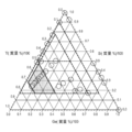
- FIG. 4 is a ternary composition diagram plotting and showing the alloy components formed in Reference Example A together with the composition range of the Si—Ti—Ge alloy constituting the negative electrode active material included in the negative electrode for an electrical device of the present invention.
- FIG. 1 is a schematic cross-sectional view schematically showing an outline of a laminated flat non-bipolar lithium ion secondary battery which is a typical embodiment of an electric device according to the present invention.
- FIG. 1 is a perspective view schematically showing the appearance of a stacked flat lithium ion secondary battery that is a representative embodiment of an electric device according to the present invention.
- FIG. 4
- FIG. 3 is a ternary composition diagram showing a preferred composition range of a Si—Ti—Ge alloy constituting the negative electrode active material of the negative electrode for an electric device of the present invention.
- FIG. 3 is a ternary composition diagram showing a more preferable composition range of a Si—Ti—Ge based alloy constituting a negative electrode active material included in a negative electrode for an electric device of the present invention.
- FIG. 3 is a ternary composition diagram showing a more preferable composition range of a Si—Ti—Ge based alloy constituting a negative electrode active material included in a negative electrode for an electric device of the present invention.
- FIG. 3 is a ternary composition diagram showing a more preferable composition range of a Si—Ti—Ge based alloy constituting a negative electrode active material included in a negative electrode for an electric device of the present invention.
- FIG. 3 is a ternary composition diagram showing an even more preferable composition range of a Si—Ti—Ge based alloy constituting the negative electrode active material included in the negative electrode for an electric device of the present invention.
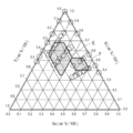
- FIG. 3 is a ternary composition diagram plotting and showing the alloy components formed in Reference Example B together with the composition range of the Si—Ti—Sn alloy constituting the negative electrode active material included in the negative electrode for an electrical device of the present invention.
- FIG. 3 is a ternary composition diagram showing a preferred composition range of a Si—Ti—Sn based alloy constituting a negative electrode active material included in a negative electrode for an electric device of the present invention.
- FIG. 3 is a ternary composition diagram showing a more preferable composition range of a Si—Ti—Sn based alloy constituting the negative electrode active material included in the negative electrode for an electric device of the present invention.
- FIG. 3 is a ternary composition diagram showing a more preferable composition range of a Si—Ti—Sn based alloy constituting the negative electrode active material included in the negative electrode for an electric device of the present invention.
- Reference Example B it is a diagram showing the influence of the negative electrode active material alloy composition on the initial discharge capacity of the batteries obtained in Reference Examples 19 to 44 and Comparative Reference Examples 14 to 27.
- Reference Example B it is a diagram showing the influence of the negative electrode active material alloy composition on the discharge capacity retention ratio at the 50th cycle of the batteries obtained in Reference Examples 19 to 44 and Comparative Reference Examples 14 to 27.
- Reference Example B it is a diagram showing the influence of the negative electrode active material alloy composition on the discharge capacity retention ratio at the 100th cycle of the batteries obtained in Reference Examples 19 to 44 and Comparative Reference Examples 14 to 27.
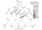
- Reference Example C the discharge capacity (mAhg) of the first cycle of the batteries using the negative electrodes in Reference Examples 45 to 56 and Reference Comparative Examples 28 to 40 is plotted according to the color of the capacity (with light and shade).
- 2 is a composition diagram of a ternary alloy of Si—Ti—Zn system.
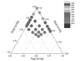
- FIG. 2 is a composition diagram of a Si—Ti—Zn ternary alloy plotted with light and shade.
- the composition range of the Si—Ti—Zn ternary alloy in FIG. 15 is color-coded for the composition ranges of the Si—Ti—Zn alloy samples in Reference Examples 45 to 56 and Reference Comparative Examples 28 to 40. It is the enclosed drawing (with light and shade).
- the composition diagram of the Si—Ti—Zn ternary alloy in FIG. 15 shows the preferred composition range among the Si—Ti—Zn alloy samples of Reference Examples 45 to 56 and Reference Comparative Examples 28 to 40. It is a drawing surrounded by color (with shading).
- the composition diagram of the Si—Ti—Zn ternary alloy in FIG. 16 shows a more preferable composition range among the Si—Ti—Zn alloy samples of Reference Examples 45 to 56 and Reference Comparative Examples 28 to 40. It is a drawing surrounded by color-coded (with shading). In the figure, 0.38 ⁇ Si (wt% / 100) ⁇ 0.72, 0.08 ⁇ Ti (wt% / 100) ⁇ 0.42, and 0.12 ⁇ Zn (wt% / 100). ⁇ 0.39.
- the composition diagram of the Si—Ti—Zn ternary alloy shown in FIG. 16 shows a particularly preferable composition range among the Si—Ti—Zn alloy samples of Reference Examples 45 to 56 and Reference Comparative Examples 28 to 40. It is a drawing surrounded by color-coded (with shading). In the figure, 0.38 ⁇ Si (wt% / 100) ⁇ 0.61, 0.19 ⁇ Ti (wt% / 100) ⁇ 0.42, and 0.12 ⁇ Zn (wt% / 100). ⁇ 0.35.
- the composition diagram of the Si—Ti—Zn ternary alloy shown in FIG. 16 shows a particularly preferable composition range among the Si—Ti—Zn alloy samples of Reference Examples 45 to 56 and Reference Comparative Examples 28 to 40. It is a drawing surrounded by color-coded (with shading).
- the present invention uses a negative electrode using a negative electrode active material in which a predetermined ternary Si alloy (ternary Si-Ti-M alloy) and a carbon-based material are mixed. It is characterized in that
- the negative electrode for an electric device according to the present invention when Si and Li are alloyed, by applying a ternary Si-Ti-M alloy, the amorphous-crystal phase transition is suppressed and the cycle life is improved. Is obtained. Furthermore, by mixing the alloy and the graphite material, it is possible to prevent the occurrence of non-uniformity of reaction with the Li ions of the Si alloy in the electrode layer (negative electrode active material layer) and to improve cycle durability. can get. As a result of such combined action, the negative electrode for an electric device according to the present invention has a high initial capacity, and has a useful effect of having high capacity and high cycle durability.
- electrode layer means a mixture layer containing a negative electrode active material, a conductive additive, and a binder, but may be referred to as a “negative electrode active material layer” in the description of this specification.
- electrode layer on the positive electrode side is also referred to as a “positive electrode active material layer”.
- the voltage of the cell is large. High energy density and high power density can be achieved. Therefore, the lithium ion secondary battery using the negative electrode for the lithium ion secondary battery of the present embodiment is excellent as a vehicle driving power source or an auxiliary power source. As a result, it can be suitably used as a lithium ion secondary battery for a vehicle driving power source or the like.
- the present invention can be sufficiently applied to lithium ion secondary batteries for portable devices such as mobile phones.
- the lithium ion secondary battery that is the subject of the present embodiment only needs to use the negative electrode for the lithium ion secondary battery of the present embodiment described below. It should not be restricted.
- the lithium ion secondary battery when distinguished by form / structure, it can be applied to any conventionally known form / structure such as a stacked (flat) battery or a wound (cylindrical) battery. Is.
- a stacked (flat) battery structure By adopting a stacked (flat) battery structure, long-term reliability can be secured by a sealing technique such as simple thermocompression bonding, which is advantageous in terms of cost and workability.
- a solution electrolyte type battery using a solution electrolyte such as a nonaqueous electrolyte solution for the electrolyte layer, a polymer battery using a polymer electrolyte for the electrolyte layer, etc. It can be applied to any conventionally known electrolyte layer type.
- the polymer battery is further divided into a gel electrolyte type battery using a polymer gel electrolyte (also simply referred to as a gel electrolyte) and a solid polymer (all solid) type battery using a polymer solid electrolyte (also simply referred to as a polymer electrolyte). It is done.
- the non-bipolar (internal parallel connection type) lithium ion secondary battery using the negative electrode for the lithium ion secondary battery of this embodiment will be described very simply with reference to the drawings.
- the technical scope of the lithium ion secondary battery of the present embodiment should not be limited to these.
- FIG. 1 schematically shows the overall structure of a flat (stacked) lithium ion secondary battery (hereinafter also simply referred to as “stacked battery”), which is a typical embodiment of the electrical device of the present invention.
- stacked battery a flat (stacked) lithium ion secondary battery
- the stacked battery 10 of the present embodiment has a structure in which a substantially rectangular power generation element 21 in which a charge / discharge reaction actually proceeds is sealed inside a laminate sheet 29 that is an exterior body.
- the positive electrode in which the positive electrode active material layer 13 is disposed on both surfaces of the positive electrode current collector 11, the electrolyte layer 17, and the negative electrode active material layer 15 is disposed on both surfaces of the negative electrode current collector 12. It has a configuration in which a negative electrode is laminated. Specifically, the negative electrode, the electrolyte layer, and the positive electrode are laminated in this order so that one positive electrode active material layer 13 and the negative electrode active material layer 15 adjacent thereto face each other with the electrolyte layer 17 therebetween. .
- the adjacent positive electrode, electrolyte layer, and negative electrode constitute one unit cell layer 19. Therefore, it can be said that the stacked battery 10 shown in FIG. 1 has a configuration in which a plurality of single battery layers 19 are stacked and electrically connected in parallel.
- the positive electrode current collector 13 on the outermost layer located on both outermost layers of the power generating element 21 is provided with the positive electrode active material layer 13 only on one side, but the active material layer may be provided on both sides. . That is, instead of using a current collector dedicated to the outermost layer provided with an active material layer only on one side, a current collector having an active material layer on both sides may be used as it is as an outermost current collector.
- the outermost negative electrode current collector is positioned on both outermost layers of the power generation element 21, and one side of the outermost negative electrode current collector or A negative electrode active material layer may be disposed on both sides.
- the positive electrode current collector 11 and the negative electrode current collector 12 are attached to a positive electrode current collector plate 25 and a negative electrode current collector plate 27 that are electrically connected to the respective electrodes (positive electrode and negative electrode), and are sandwiched between end portions of the laminate sheet 29. Thus, it has a structure led out of the laminate sheet 29.
- the positive electrode current collector plate 25 and the negative electrode current collector plate 27 are ultrasonically welded to the positive electrode current collector 11 and the negative electrode current collector 12 of each electrode via a positive electrode lead and a negative electrode lead (not shown), respectively, as necessary. Or resistance welding or the like.
- the lithium ion secondary battery described above is characterized by a negative electrode.
- main components of the battery including the negative electrode will be described.
- the active material layer 13 or 15 contains an active material, and further contains other additives as necessary.
- the positive electrode active material layer 13 includes a positive electrode active material.
- Positive electrode active material examples include lithium-transition metal composite oxides, lithium-transition metal phosphate compounds, lithium-transition metal sulfate compounds, solid solution systems, ternary systems, NiMn systems, NiCo systems, and spinel Mn systems. It is done.
- lithium-transition metal composite oxide examples include LiMn 2 O 4 , LiCoO 2 , LiNiO 2 , Li (Ni, Mn, Co) O 2 , Li (Li, Ni, Mn, Co) O 2 , LiFePO 4 and Examples include those in which some of these transition metals are substituted with other elements.
- Examples of the ternary system include nickel / cobalt / manganese (composite) cathode materials.
- NiMn system examples include LiNi 0.5 Mn 1.5 O 4 .
- NiCo system examples include Li (NiCo) O 2 .
- Examples of the spinel Mn system include LiMn 2 O 4 .
- two or more positive electrode active materials may be used in combination.
- a lithium-transition metal composite oxide is used as the positive electrode active material.
- positive electrode active materials other than those described above may be used.
- the optimum particle size may be blended and used for expressing each unique effect. It is not always necessary to make the particle diameter uniform.
- the average particle diameter of the positive electrode active material contained in the positive electrode active material layer 13 is not particularly limited, but is preferably 1 to 30 ⁇ m and more preferably 5 to 20 ⁇ m from the viewpoint of increasing the output.
- the “particle diameter” refers to the outline of the active material particles (observation surface) observed using an observation means such as a scanning electron microscope (SEM) or a transmission electron microscope (TEM). It means the maximum distance among any two points.
- the value of “average particle diameter” is the value of particles observed in several to several tens of fields using observation means such as a scanning electron microscope (SEM) or a transmission electron microscope (TEM). The value calculated as the average value of the particle diameter shall be adopted.
- the particle diameters and average particle diameters of other components can be defined in the same manner.
- the positive electrode (positive electrode active material layer) can be applied by any one of a kneading method, a sputtering method, a vapor deposition method, a CVD method, a PVD method, an ion plating method, and a thermal spraying method in addition to a method of applying (coating) a normal slurry. Can be formed.
- the negative electrode active material layer 15 includes a negative electrode active material.
- the negative electrode active material is a mixture of a predetermined alloy and a carbon-based material.
- alloy is represented by the following chemical formula (1).
- M is at least one metal selected from the group consisting of Ge, Sn, Zn, and combinations thereof.
- A is an inevitable impurity.
- x, y, z, and a represent mass% values, where 0 ⁇ x ⁇ 100, 0 ⁇ y ⁇ 100, 0 ⁇ z ⁇ 100, and 0 ⁇ a ⁇ 0.5.
- X + y + z + a 100.
- the “inevitable impurity” means an Si alloy that is present in a raw material or inevitably mixed in a manufacturing process. The inevitable impurities are originally unnecessary impurities, but are a very small amount and do not affect the characteristics of the Si alloy.
- the first additive element Ti and the second additive element M are used as the negative electrode active material.
- the selection it is possible to improve the cycle life by suppressing the amorphous-crystal phase transition during Li alloying. This also makes the capacity higher than that of a conventional negative electrode active material, for example, a carbon-based negative electrode active material.
- the amorphous-crystal phase transition is suppressed because, in the Si material, when Si and Li are alloyed, the amorphous state transitions to the crystalline state, causing a large volume change (about 4 times). For this reason, the particles themselves are broken and the function as the active material is lost. Therefore, by suppressing the amorphous-crystal phase transition, it is possible to suppress the collapse of the particles themselves, maintain the function as the active material (high capacity), and improve the cycle life.
- a Si alloy negative electrode active material having a high capacity and high cycle durability can be provided.
- M is at least one metal selected from the group consisting of Ge, Sn, Zn, and combinations thereof. Accordingly, the Si alloys of Si x Ti y Ge z A a , Si x Ti y Sn z A a , and Si x Ti yZnz A a will be described below.
- the Si x Ti y Ge z A a is selected from the first additive element Ti and the second additive element Ge, so that the amorphous-crystalline phase is formed during the Li alloying.
- the cycle life can be improved by suppressing the transition. This also makes the capacity higher than that of a conventional negative electrode active material, for example, a carbon-based negative electrode active material.
- x is 17 or more and less than 90
- y is more than 10 and less than 83
- z is more than 0 and less than 73.
- the x is 17 to 77, the y is 20 to 80, and the z is 3 to 63 as shown by the shaded portion in FIG. It is preferable to be in the range. Further, as shown in the shaded portion of FIG. 5, more preferably, y is set to a range of 68 or less. Then, as shown in the shaded portion of FIG. 6, it is more preferable that x is in the range of 50 or less. Further, as shown in the shaded portion of FIG. 7, most preferably, the y is further set to a range of 51% or more.
- A is an impurity (unavoidable impurity) other than the above three components derived from the raw materials and the manufacturing method.
- the a is 0 ⁇ a ⁇ 0.5, and preferably 0 ⁇ a ⁇ 0.1.
- the Si x Ti y Sn z A a is selected from the first additive element Ti and the second additive element Sn, so that an amorphous-crystalline phase is formed during Li alloying.
- the cycle life can be improved by suppressing the transition. This also makes the capacity higher than that of a conventional negative electrode active material, for example, a carbon-based negative electrode active material.
- x, y, and z are the following formulas (1) or (2):
- the titanium content is in the range of 7% by mass or more. That is, as indicated by reference C in FIG. 9, the first region has a silicon (Si) content of 35% to 78% by mass, tin (Sn) of 7% to 30% by mass, and 7% by mass or more. A region containing 37 mass% or less of titanium (Ti) is preferable. Moreover, as shown by the code
- the discharge capacity retention rate after 50 cycles can be 45% or more.
- the first region includes 35 mass% to 68 mass% Si, 7 mass% to 30 mass% Sn.
- the region containing Ti of 18% by mass or more and 37% by mass or less is preferable.
- the second region includes 39% by mass to 52% by mass Si, 30% by mass to 51% by mass Sn, and 7% by mass to 20% by mass Ti. It is desirable that the region includes That is, the x, y, and z are represented by the following formula (5) or (6):
- the negative electrode active material of the present embodiment includes an alloy containing the components in the region indicated by symbol G in FIG. 11 and the balance being inevitable impurities.
- symbol G is an area
- a is 0 ⁇ a ⁇ 0.5, and preferably 0 ⁇ a ⁇ 0.1.
- the Si x Ti y Zn z A a is selected from the first additive element Ti and the second additive element Zn.
- the cycle life can be improved by suppressing the transition. This also makes the capacity higher than that of a conventional negative electrode active material, for example, a carbon-based negative electrode active material.
- the x, y, and z are represented by the following formula (8):
- the composition ratio of the Si—Ti—Zn alloy is within the range surrounded by the thick solid line in FIG. 17 (inside the triangle), the composition ratio is extremely high, which cannot be achieved with existing carbon-based negative electrode active materials. Capacitance can be realized. Similarly, a higher capacity (initial capacity of 690 mAh / g or more) can be realized than the existing Sn-based alloy negative electrode active material.
- the x, y, and z are represented by the following formula (9):
- the Si alloy negative electrode active material having good characteristics is obtained.
- a higher capacity (initial capacity of 690 mAh / g or more) can be realized than the existing Sn-based alloy negative electrode active material.
- the cycle durability that is in a trade-off relationship with the increase in capacity, when compared with the Sn-based negative electrode active material having a high capacity but poor cycle durability and the multi-component alloy negative electrode active material described in Patent Document 1, Can realize extremely excellent cycle durability. Specifically, a high discharge capacity retention ratio of 87% or more at the 50th cycle can be realized. Thereby, an excellent Si alloy negative electrode active material can be provided (see Table 3 and FIGS. 15, 16, and 18).
- the x, y, and z are represented by the following formula (10):
- the Si alloy negative electrode having better characteristics An active material can be provided. Specifically, even when the composition ratio of the Si—Ti—Zn alloy is within the range surrounded by the thick solid line in FIG. 19 (inside the hexagon), it is remarkably impossible with the existing carbon-based negative electrode active material. High capacity can be realized. Similarly, a higher capacity (initial capacity of 690 mAh / g or more) can be realized than the existing Sn-based alloy negative electrode active material.
- the x, y, and z are represented by the following formula (11):
- the Si alloy negative electrode having particularly good characteristics when the composition ratio of the first additive element Ti and the second additive element Zn, and further the high-capacity element Si is within the appropriate range specified above.
- An active material can be provided. Specifically, even when the composition ratio of the Si—Ti—Zn alloy is within the range surrounded by the thick solid line in FIG. 20 (the inside of the small hexagon), it is not possible with the existing carbon-based negative electrode active material. High capacity can be realized. Similarly, a higher capacity (initial capacity of 690 mAh / g or more) can be realized than the existing Sn-based alloy negative electrode active material.
- the x, y, and z are represented by the following formula (12):
- the Si alloy negative electrode having the best characteristics when the composition ratio of the first additive element Ti and the second additive element Zn, and further the high-capacity element Si is within the appropriate range specified above.
- An active material can be provided. Specifically, when the composition ratio of the Si—Ti—Zn alloy is within the range surrounded by the thick solid line in FIG. 21 (the inside of the small square), it is remarkably impossible with existing carbon-based negative electrode active materials. High capacity can be realized. Similarly, higher capacity (initial capacity of 1129 mAh / g or more) can be realized even when compared with existing Sn-based alloy negative electrode active materials.
- the initial capacity (discharge capacity at the first cycle) is much higher than the existing carbon-based negative electrode active material (theoretical capacity 372 mAh / g).
- the capacity is higher than that of the Sn-based negative electrode active material (theoretical capacity is about 600 to 700 mAh / g).
- the cycle characteristics are very poor and sufficient when compared with the discharge capacity retention ratio (about 60%) of the 50th cycle of the Sn-based negative electrode active material that can be increased in capacity to about 600 to 700 mAh / g. There wasn't. That is, the balance between the increase in capacity and the cycle durability, which are in a trade-off relationship, is poor and cannot be put into practical use.
- the negative electrode active material using the ternary alloy represented by Si x Ti y Zn z (A a ) of the present embodiment has a high discharge capacity maintenance ratio at the 50th cycle as high cycle characteristics (FIG. 16). reference). Furthermore, the initial capacity (the discharge capacity at the first cycle) is much higher than that of the existing carbon-based negative electrode active material, and is equal to or higher than that of the existing Sn-based negative electrode active material (see FIG. 15).
- the negative electrode active material shown can be provided. That is, both the characteristics of high capacity and cycle durability, which could not be realized due to a trade-off relationship with existing carbon-based and Sn-based negative electrode active materials and ternary and quaternary alloys described in Patent Document 1,
- the present inventors have found a negative electrode active material using an alloy that can be formed in a high-dimensional and well-balanced manner. Specifically, it has been found that the intended purpose can be achieved by selecting two types of Ti and Zn from the group consisting of one or more additive element species in which there are very various combinations. It is. As a result, it is excellent in that a lithium ion secondary battery having a high capacity and good cycle durability can be provided.
- the range of x in the formula (2) which is the mass% value of Si in the alloy having the composition formula Si x Ti y Zn z A a , is preferably 38. ⁇ x ⁇ 100, more preferably 38 ⁇ x ⁇ 72, still more preferably 38 ⁇ x ⁇ 61, and particularly preferably 47 ⁇ x ⁇ 53 (see Table 3, FIGS. 17 to 21). .
- a negative electrode which maintains a high cycle characteristic (particularly, a high discharge capacity maintenance ratio at the 50th cycle) and a high initial capacity in a well-balanced manner.
- a range of 38 ⁇ x ⁇ 72 is desirable.
- the composition ratio of Ti, which is the first additive element and Zn, which is the second additive element described later is appropriate, good characteristics (high capacity that is in a trade-off relationship with existing alloy-based negative electrode active materials) And a Si alloy negative electrode active material having characteristics excellent in both cycle durability) (see Reference Examples 45 to 56 of Reference Example C in Table 3 and FIG. 19).
- the mass% value (x value) of the high-capacity element Si in the alloy is a negative electrode active material that maintains a high cycle characteristic (higher discharge capacity retention ratio) while maintaining a high initial capacity in a well-balanced manner. From the viewpoint of providing, it can be said that the range of 38 ⁇ x ⁇ 61 is more desirable.
- a Si alloy negative electrode active material having better characteristics can be provided (Table 3 and FIG. (Internal reference surrounded by 20 thick solid lines).
- a negative electrode active material that maintains a particularly high cycle characteristic (particularly a high discharge capacity retention ratio) and a high initial capacity in a well-balanced manner. From the viewpoint of providing, it can be said that the range of 47 ⁇ x ⁇ 53 is particularly desirable.
- a high-performance Si alloy negative electrode active material having the best characteristics can be provided (Table 1). 3 and the internal reference surrounded by the thick solid line in FIG. 21).
- the particularly preferable range of 47 ⁇ x ⁇ 53 is particularly excellent in that a high capacity (1129 mAh / g or more) and a particularly high discharge capacity maintenance rate (95% or more) in the 50th cycle can be maintained. (Internal reference enclosed in thick solid line in Table 3 and FIG. 21).
- the Si material (x value) having the initial capacity of 3200 mAh / g, the first additive element Ti (y value), and the second additive element Zn (z value) can be in an optimal range (see the range surrounded by the thick solid line in FIGS. 17 to 21). Therefore, it is excellent in that the most favorable characteristics can be expressed and the increase in capacity at the vehicle application level can be stably and safely maintained over a long period of time.
- the content ratio of the high capacity Si material having an initial capacity of 3200 mAh / g, the first additive element Ti, and the second additive element Zn can be an optimum range (see the range surrounded by the thick solid line in FIGS. 17 to 21). Therefore, when alloying Si and Li, the amorphous-crystal phase transition can be remarkably suppressed, and the cycle life can be greatly improved. That is, it is possible to achieve a discharge capacity maintenance ratio of 87% or more, particularly 90% or more, especially 96% or more in the 50th cycle.
- Patent Document 1 it is disclosed in the above-mentioned embodiment of Patent Document 1 that the degradation of cycle characteristics due to a considerable capacity reduction is already exhibited in only about 5 to 6 cycles. That is, in the example of Patent Document 1, the discharge capacity maintenance rate at the 5th to 6th cycles has already been reduced to 90 to 95%, and the discharge capacity maintenance rate at the 50th cycle has been reduced to almost 50 to 0%. It will be.
- the combination of the first additive element Ti and the second additive element Zn to the high-capacity Si material is in a mutually complementary relationship, so to speak, many trials and errors, and various additions (metal or nonmetal). It can be selected through undue experimentation with combinations of elements.
- the range of y in the formula (3) which is the mass% value of Ti in the alloy having the composition formula Si x Ti y Zn z A a , is preferably 0. ⁇ Y ⁇ 62, more preferably 0 ⁇ y ⁇ 42, still more preferably 8 ⁇ y ⁇ 42, particularly preferably 19 ⁇ y ⁇ 42, and most preferably 19 ⁇ y ⁇ 21. .
- the numerical value of the mass percentage (y value) of the first additive element Ti in the alloy is in the range of 0 ⁇ y ⁇ 62, the high capacity Si is obtained due to the characteristics of Ti (and the synergistic characteristics with Zn).
- the amorphous-crystal phase transition of the material can be effectively suppressed.
- an effect excellent in cycle life (cycle durability), in particular, a high discharge capacity retention rate (87% or more) at the 50th cycle can be expressed (see Table 3 and FIG. 17).
- the content x value of the high-capacity Si material can be kept above a certain value (38 ⁇ x ⁇ 100), and a much higher capacity that cannot be realized with existing carbon-based negative electrode active materials can be achieved. realizable.
- an alloy having the same or higher capacity (initial capacity of 690 mAh / g or more) can be obtained even when compared with an existing Sn-based alloy negative electrode active material (see Table 3 and FIG. 17).
- the mass% value (y value) of the first additive element Ti in the alloy is preferably a good balance between the characteristics with a high initial capacity while maintaining a high cycle characteristic (particularly a high discharge capacity retention rate at the 50th cycle). From the viewpoint of providing the negative electrode active material shown, a range of 0 ⁇ y ⁇ 42 is desirable. When the content ratio of the first additive element Ti having an effect of suppressing the amorphous-crystal phase transition and improving the cycle life is appropriate at the time of forming the Li alloy, an Si alloy negative electrode active material having good characteristics is obtained. (See Table 3 and the composition range surrounded by the thick solid line in FIG. 18).
- the cycle durability is far superior to Sn-based negative electrode active materials and multi-component alloy negative electrode active materials described in Patent Document 1.
- a Si alloy negative electrode active material realizing a discharge capacity retention rate of 87% or more can be provided (see Table 3 and FIG. 18).
- the mass% value (y value) of the first additive element Ti in the alloy shows a high balance of the characteristics with high initial capacity while maintaining high cycle characteristics (high discharge capacity retention ratio at the 50th cycle). From the viewpoint of providing the negative electrode active material, it can be said that the range of 8 ⁇ y ⁇ 42 is desirable.
- the content ratio of the first additive element Ti having an effect of suppressing the amorphous-crystal phase transition and improving the cycle life is appropriate at the time of forming the Li alloy, an Si alloy negative electrode active material having good characteristics is obtained. (See Table 3 and FIG. 19).
- the capacity is increased and it is markedly superior to the Sn-based negative electrode active material and the multi-component alloy negative electrode active material described in Patent Document 1.
- the mass% value (y value) of the first additive element Ti in the alloy while maintaining higher cycle characteristics (high discharge capacity retention rate at the 50th cycle), the characteristics of the initial capacity are also very high. From the viewpoint of providing a negative electrode active material that is well-balanced, a range of 19 ⁇ y ⁇ 42 is desirable.
- the content ratio of the first additive element Ti which has the effect of suppressing the amorphous-crystal phase transition and improving the cycle life, is more appropriate when forming the Li alloy, the Si alloy negative electrode active material having even better characteristics can be obtained. Substances can be provided (see Table 3 and FIG. 20).
- the mass% value (y value) of the first additive element Ti in the alloy is preferably the highest balance between the characteristics with high initial capacity while maintaining higher cycle characteristics (high discharge capacity retention rate at the 50th cycle).
- the range of 19 ⁇ y ⁇ 21 is desirable from the viewpoint of providing a well-shown negative electrode active material.
- the Si alloy negative electrode active material having the best characteristics is most suitable. Substances can be provided (see Table 3 and FIG. 21).
- the negative electrode active material (negative electrode) is excellent in that it can exhibit the best characteristics and can maintain a high capacity at the vehicle application level stably and safely over a long period of time.
- the inclusion of a high-capacity Si material having an initial capacity of about 3200 mAh / g and the first additive element Ti (and also the second additive element Zn) The ratio (balance) can be in an optimum range (see the range surrounded by the thick solid line in FIGS. 18 to 21). Therefore, when alloying Si and Li, the amorphous-crystal phase transition can be remarkably suppressed, and the cycle life can be greatly improved.
- Patent Document 1 it is disclosed in the above-mentioned embodiment of Patent Document 1 that the degradation of cycle characteristics due to a considerable capacity reduction is already exhibited in only about 5 to 6 cycles. That is, in the example of Patent Document 1, the discharge capacity maintenance rate at the 5th to 6th cycles has already been reduced to 90 to 95%, and the discharge capacity maintenance rate at the 50th cycle has been reduced to almost 50 to 0%. It will be.
- the first additive element Ti and the combination of the second additive element Zn, which is a mutually complementary relationship
- the high-capacity Si material a number of trials and errors, and various additions ( It can be selected through undue experimentation with combinations of elements (metal or non-metal) (only one combination).
- the range of z in the formula (4) which is the mass% value of Zn in the alloy having the composition formula Si x Ti y Zn z A a , is preferably 0. ⁇ Z ⁇ 62, more preferably 0 ⁇ z ⁇ 39, still more preferably 12 ⁇ z ⁇ 39, particularly preferably 12 ⁇ z ⁇ 35, and particularly preferably 26 ⁇ z ⁇ 35. . This is because, when the concentration of the first additive element in the alloy increases, the capacity as an electrode does not decrease, and the mass% value (z value) of the second additive element species Zn is in the range of 0 ⁇ z ⁇ 62.
- the amorphous-crystal phase transition of the high-capacity Si material can be effectively suppressed.
- an effect excellent in cycle life (cycle durability), in particular, a high discharge capacity retention rate (87% or more) at the 50th cycle can be expressed (see Table 3 and FIG. 17).
- the content x value of the high-capacity Si material can be maintained at a certain value (38 ⁇ x ⁇ 100), and the capacity can be significantly increased as compared with existing carbon-based negative electrode active materials.
- An alloy having a high capacity equal to or higher than that of the negative electrode active material can be obtained (see FIG. 17).
- the high discharge capacity maintenance ratio at the 50th cycle cannot be sufficiently maintained (see Comparative Reference Examples 28 to 40 in FIG. 3 and FIG. 16), and the major problem is that the cycle characteristics rapidly deteriorate (deteriorate). Arise.
- z ⁇ 62 the characteristics as the negative electrode active material can be sufficiently exhibited, which can contribute to the development of high capacity and cycle durability.
- the mass% value (z value) of the second additive element Zn in the alloy preferably maintains a high cycle characteristic (particularly, a high discharge capacity retention rate at the 50th cycle) and a high initial capacity characteristic in a well-balanced manner.
- a range of 0 ⁇ z ⁇ 39 is desirable.
- the capacity of the first additive element Ti which suppresses the amorphous-crystal phase transition and improves the cycle life, and the negative electrode active material (negative electrode) does not decrease even when the concentration of the first additive element increases. Selection of the second additive element Zn is extremely important and useful in the present embodiment.
- first and second additive elements With such first and second additive elements, a known ternary alloy, a quaternary or higher alloy such as Patent Document 1, and a binary alloy such as a Si—Ti alloy or a Si—Zn alloy can be used. It was found that there was a significant difference in action and effect. When the content ratio of the second additive element Zn (and the first additive element Ti mutually complementary to Zn) is appropriate, a Si alloy negative electrode active material having good characteristics is obtained (Table 3 and FIG. 18). (See composition range surrounded by thick solid line).
- the mass% value (z value) of the second additive element Zn in the alloy balances the characteristics with high initial capacity while maintaining high cycle characteristics due to the synergistic effect (mutual complementary characteristics) with the first additive element Ti.
- z value mass% value
- the mass% value (z value) of the second additive element Zn in the alloy balances the characteristics with high initial capacity while maintaining high cycle characteristics due to the synergistic effect (mutual complementary characteristics) with the first additive element Ti.
- a range of 12 ⁇ z ⁇ 39 is desirable.
- Good when the content ratio of the second additive element Zn is appropriate, which can achieve the effect of suppressing the amorphous-crystal phase transition and improving the cycle life by synergistic effect (mutual complementarity) with Ti during Li alloying This is because a Si alloy negative electrode active material having excellent characteristics can be provided.
- the capacity is increased by synergistic properties with Ti and compared with the Sn-based negative electrode active material and the multi-component alloy negative electrode active material described in Patent Document 1. Even in this case, it is possible to provide a Si alloy negative electrode active material that realizes remarkably excellent cycle durability.
- the mass% value (z value) of the second additive element Zn in the alloy has a very high initial capacity while maintaining a higher cycle characteristic (high discharge capacity retention rate at the 50th cycle). From the viewpoint of providing a negative electrode active material that is well-balanced, a range of 12 ⁇ z ⁇ 35 is desirable.
- the content ratio of the second additive element Zn which can exhibit the effect of suppressing the amorphous-crystal phase transition and improving the cycle life due to the synergistic effect (mutual complementary characteristics) with Ti, is more appropriate during Li alloying This is because a Si alloy negative electrode active material having even better characteristics can be provided.
- the effect of suppressing the amorphous-crystal phase transition and improving the cycle life is more effective when alloying due to the synergistic effect (mutual complementarity) with Ti. Can be expressed.
- it is possible to maintain a higher discharge capacity maintenance rate of 90% or more at the 50th cycle see Table 3 and FIG. 20.
- a composition range in which a high capacity and a high discharge capacity retention ratio of 90% or more at the 50th cycle can be realized is particularly, the Zn content is 12%).
- ⁇ z ⁇ 35) is selected (small hexagons surrounded by thick solid lines in FIG. 20).
- the mass% value (z value) of the second additive element Zn in the alloy is preferably the highest balance between the characteristics with high initial capacity while maintaining higher cycle characteristics (high discharge capacity retention rate at the 50th cycle).
- the range of 26 ⁇ z ⁇ 35 is desirable from the viewpoint of providing a well-shown negative electrode active material.
- the effect of suppressing the amorphous-crystal phase transition and improving the cycle life is more effective when alloying due to the synergistic effect (mutual complementarity) with Ti. Can be expressed.
- an even higher discharge capacity retention rate of 96% or more at the 50th cycle can be maintained (see Table 3 and FIG. 21).
- a composition range (particularly Zn content) in which a further higher capacity and a high discharge capacity retention rate of 96% or more at the 50th cycle were realized. Is selected (26 ⁇ z ⁇ 35) (a square surrounded by a thick solid line in FIG. 21).
- the content ratio (balance) of the high-capacity Si material having an initial capacity of 3200 mAh / g and the first additive element Ti and the further second additive element Zn. Can be the optimum range (see the range surrounded by the thick solid line in FIGS. 19 to 21). Therefore, even if the Ti concentration that can suppress the phase transition of amorphous-crystal, which is a characteristic of Zn (synergistic effect with Ti; mutual complementarity characteristics), increases the capacity as the negative electrode active material (negative electrode). Therefore, the cycle life (particularly the discharge capacity maintenance rate) can be significantly improved.
- the negative electrode active material (negative electrode) is excellent in that it can exhibit the best characteristics and can maintain a high capacity at the vehicle application level stably and safely over a long period of time.
- the content ratio (balance) of the high-capacity Si material having an initial capacity of 3200 mAh / g and the first additive element Ti and the second additive element Zn is optimal. It can be a range (see the range surrounded by the thick solid line in FIGS. 18 to 21).
- the amorphous-crystal phase transition can be remarkably suppressed, and the cycle life (especially the discharge capacity retention rate at the 50th cycle) can be greatly improved. That is, the discharge capacity maintenance rate at the 50th cycle can be 87% or more, particularly 90% or more, and particularly 96% or more.
- the discharge capacity maintenance rate at the 50th cycle can be 87% or more, particularly 90% or more, and particularly 96% or more.
- the above-described effects of the present embodiment are effectively expressed. Needless to say, it is included in the technical scope (right range) of the present invention as long as it can be performed.
- Patent Document 1 it is disclosed in the above-mentioned embodiment of Patent Document 1 that the degradation of cycle characteristics due to a considerable capacity reduction is already exhibited in only about 5 to 6 cycles. That is, in the example of Patent Document 1, the discharge capacity maintenance rate at the 5th to 6th cycles has already been reduced to 90 to 95%, and the discharge capacity maintenance rate at the 50th cycle has been reduced to almost 50 to 0%. It will be.
- the combination of the first additive element Ti and the second additive element Zn to the high-capacity Si material is in a mutually complementary relationship, so to speak, many trials and errors, and various additions (metal or nonmetal). It can be selected through an excessive experiment with combinations of elemental species (only one combination).
- the reduction of the discharge capacity maintenance ratio at the 50th cycle can be greatly reduced by further making the Zn content within the optimum range shown above. That is, when Si and Li are alloyed, the crystal is crystallized from an amorphous state by a particularly remarkable synergistic effect (effect) due to the optimum range of the second additive element Zn (and the first additive element Ti mutually complementary to Zn). The transition to the state can be suppressed, and a large volume change can be prevented. Furthermore, it is excellent also in that the high cycle durability of the electrode can be improved while showing a high capacity.
- Mass% value of A in the alloy The range of a in the formula (5), which is the mass% value of A in the alloy having the composition formula Si x Ti y Zn z A a , is 0 ⁇ a ⁇ 0.5, preferably 0 ⁇ x ⁇ 0.1.
- A is present in the raw material in the Si alloy or is inevitably mixed in the manufacturing process, and is originally unnecessary, but it is a trace amount and affects the characteristics of the Si alloy. Therefore, it is allowed to be contained in the alloy.
- the average particle diameter of the Si alloy is not particularly limited as long as it is approximately the same as the average particle diameter of the negative electrode active material included in the existing negative electrode active material layer 15. From the viewpoint of higher output, it is preferably in the range of 1 to 20 ⁇ m. However, it is not limited at all to the above range, and it goes without saying that it may be outside the above range as long as the effects of the present embodiment can be effectively expressed.
- the shape of the Si alloy is not particularly limited, and may be spherical, elliptical, cylindrical, polygonal, scaly, indeterminate, or the like.
- a method for producing an alloy having a composition formula Si x Ti y M z A a according to the manufacturing method according to this embodiment of the alloy is not limited in particular, can be produced by utilizing the production of conventionally known various . That is, since there is almost no difference in the alloy state and characteristics depending on the production method, various production methods can be applied.
- a mechanical alloy method, an arc plasma melting method, or the like can be used as a method for producing a particle form of an alloy having the composition formula Si x Ti y M z A a .
- a slurry in the method of manufacturing in the form of the above particles, can be prepared by adding a binder, a conductive additive and a viscosity adjusting solvent to the particles, and a slurry electrode can be formed using the slurry. Therefore, it is excellent in that it is easy to mass-produce (mass production) and to be practically used as an actual battery electrode.
- Carbon-based material The carbon-based material that can be used in the present invention is not particularly limited, but is graphite (graphite) that is highly crystalline carbon such as natural graphite or artificial graphite; low-crystalline carbon such as soft carbon or hard carbon; Carbon black such as chain black, acetylene black, channel black, lamp black, oil furnace black, and thermal black; and carbon materials such as fullerene, carbon nanotube, carbon nanofiber, carbon nanohorn, and carbon fibril. Of these, graphite is preferably used.
- graphite graphite
- highly crystalline carbon such as natural graphite or artificial graphite
- low-crystalline carbon such as soft carbon or hard carbon
- Carbon black such as chain black, acetylene black, channel black, lamp black, oil furnace black, and thermal black
- carbon materials such as fullerene, carbon nanotube, carbon nanofiber, carbon nanohorn, and carbon fibril.
- graphite is preferably used.
- the negative electrode active material is mixed with a carbon-based material together with the above alloy, so that it is possible to maintain a high cycle characteristic and to have a high initial capacity and a well-balanced characteristic.
- the Si alloy may not be uniformly arranged in the negative electrode active material layer. In such a case, the electric potential and capacity which each Si alloy expresses differ individually. As a result, in the Si alloy in the negative electrode active material layer, a Si alloy that reacts excessively with Li ions and a Si alloy that does not react with Li ions are generated. That is, non-uniformity of reaction with Li ions of the Si alloy in the negative electrode active material layer occurs. Then, among the above alloys, the Si alloy that reacts with Li ions excessively acts, so that the decomposition of the electrolytic solution due to a significant reaction with the electrolytic solution and the destruction of the structure of the Si alloy due to excessive expansion may occur. As a result, even when a Si alloy having excellent characteristics is used, when the Si alloy is not uniformly disposed, the cycle characteristics can be deteriorated as a negative electrode for an electric device.
- the above problem can be solved by mixing the Si alloy with a carbon-based material. More specifically, by mixing the Si alloy with the carbon-based material, it may be possible to uniformly dispose the Si alloy in the negative electrode active material layer. As a result, all of the Si alloys in the negative electrode active material layer exhibit the same reactivity, and can prevent deterioration of cycle characteristics.
- the initial capacity can be reduced by reducing the content of the Si alloy in the negative electrode active material layer.
- the carbon-based material itself has reactivity with Li ions, the degree of decrease in the initial capacity is relatively small. That is, the negative electrode active material according to the present embodiment has a large effect of improving the cycle characteristics as compared with the effect of reducing the initial capacity.
- the carbon-based material is unlikely to change in volume when reacting with Li ions as compared with the Si alloy. Therefore, even when the volume change of the Si alloy is large, when the negative electrode active material is taken as a whole, the influence of the volume change of the negative electrode active material associated with the Li reaction can be made relatively minor.
- Such an effect can be understood from the results of Examples in which the cycle characteristics increase as the content of the carbon-based material increases (the content of the Si alloy decreases) (Table 4 and FIG. 23). See).
- the amount of electricity consumed (Wh) can be improved by containing a carbon-based material. More specifically, the carbon-based material has a relatively low potential compared to the Si alloy. As a result, the relatively high potential of the Si alloy can be reduced. Then, since the electric potential of the whole negative electrode falls, power consumption (Wh) can be improved. Such an action is particularly advantageous when used in, for example, a vehicle application among electric devices.
- the shape of the carbon-based material is not particularly limited, and may be spherical, elliptical, cylindrical, polygonal, scaly, indefinite, or the like.
- the average particle diameter of the carbon-based material is not particularly limited, but is preferably 5 to 25 ⁇ m, and more preferably 5 to 10 ⁇ m.
- the average particle diameter of the carbon-based material may be the same as or different from the average particle diameter of the Si alloy. preferable.
- the average particle size of the alloy is more preferably smaller than the average particle size of the carbonaceous material.
- the ratio of the average particle size of the carbon-based material to the average particle size of the Si alloy is preferably 1/250 to less than 1, It is more preferably 1/100 to 1/4.
- the mixing ratio of the Si alloy of the negative electrode active material and the carbon-based material is not particularly limited, and can be appropriately selected according to a desired application.
- the content of the alloy in the negative electrode active material is preferably 3 to 70% by mass.
- the content of the alloy in the negative electrode active material is more preferably 30 to 50% by mass.
- the content of the alloy in the negative electrode active material is more preferably 50 to 70% by mass.
- the content of the alloy is 3% by mass or more because a high initial capacity can be obtained.
- the content of the alloy is 70% by mass or less, it is preferable because high cycle characteristics can be obtained.
- the negative electrode active material is not particularly limited, and can be produced by a known method.
- the negative electrode active material layer may use the above-described method for producing an alloy. Specifically, using a mechanical alloy method, an arc plasma melting method or the like to produce a Si alloy in a particle form, a slurry is prepared by adding a carbon-based material, a binder, a conductive additive, and a mucus modifier. A slurry electrode can be formed using the slurry. Under the present circumstances, the negative electrode active material from which Si alloy becomes desired content can be manufactured by changing suitably the quantity of Si alloy of a particle form, and the quantity of carbonaceous material.
- the positive electrode active material layer 13 and the negative electrode active material layer 15 include a binder, a conductive additive, an electrolyte salt (lithium salt), an ion conductive polymer, and the like.
- the binder used for the binder active material layer is not particularly limited, and examples thereof include the following materials. Polyethylene, polypropylene, polyethylene terephthalate (PET), polyether nitrile (PEN), polyacrylonitrile, polyimide, polyamide, polyamideimide, cellulose, carboxymethylcellulose (CMC), ethylene-vinyl acetate copolymer, polyvinyl chloride, styrene / butadiene Rubber (SBR), isoprene rubber, butadiene rubber, ethylene / propylene rubber, ethylene / propylene / diene copolymer, styrene / butadiene / styrene block copolymer and hydrogenated product thereof, styrene / isoprene / styrene block copolymer and Thermoplastic polymers such as hydrogenated products, polyvinylidene fluoride (PVdF), polytetrafluoroethylene (PT
- polyvinylidene fluoride, polyimide, styrene / butadiene rubber, carboxymethyl cellulose, polypropylene, polytetrafluoroethylene, polyacrylonitrile, polyamide, and polyamideimide are more preferable, and polyamide is more preferable.
- These suitable binders are excellent in heat resistance, have a very wide potential window, are stable at both the positive electrode potential and the negative electrode potential, and can be used for the active material layer. Further, a binder having a relatively strong binding force such as polyamide can favorably hold the Si alloy on the carbon-based material. These binders may be used alone or in combination of two.
- the amount of the binder contained in the active material layer is not particularly limited as long as it is an amount capable of binding the active material, but is preferably 0.5 to 15% by mass with respect to the active material layer. More preferably, it is 1 to 10% by mass.
- Conductive auxiliary agent means the additive mix
- Examples of the conductive assistant include carbon materials such as carbon black such as acetylene black, graphite, and vapor grown carbon fiber.
- the conductive binder having the functions of the conductive assistant and the binder may be used in place of the conductive assistant and the binder, or may be used in combination with one or both of the conductive assistant and the binder.
- Commercially available TAB-2 (manufactured by Hosen Co., Ltd.) can be used as the conductive binder.
- the content of the conductive additive mixed into the active material layer is in the range of 1% by mass or more, more preferably 3% by mass or more, and further preferably 5% by mass or more with respect to the total amount of the active material layer.
- the content of the conductive additive mixed in the active material layer is 15% by mass or less, more preferably 10% by mass or less, and further preferably 7% by mass or less with respect to the total amount of the active material layer. is there.
- Electrolyte salt lithium salt
- Examples of the electrolyte salt (lithium salt) include Li (C 2 F 5 SO 2 ) 2 N, LiPF 6 , LiBF 4 , LiClO 4 , LiAsF 6 , LiCF 3 SO 3 and the like.
- Ion conductive polymer examples include polyethylene oxide (PEO) -based and polypropylene oxide (PPO) -based polymers.
- the compounding ratio of the components contained in the negative electrode active material layer in the case of using the positive electrode active material layer and the alloy in the form of particles of (5) (ii) above is not particularly limited.
- the mixing ratio can be adjusted by appropriately referring to known knowledge about the non-aqueous solvent secondary battery.
- each active material layer (active material layer on one side of the current collector) is not particularly limited, and conventionally known knowledge about the battery can be appropriately referred to.
- the thickness of each active material layer is usually about 1 to 500 ⁇ m, preferably 2 to 100 ⁇ m, taking into consideration the intended use of the battery (emphasis on output, energy, etc.) and ion conductivity.
- the current collectors 11 and 12 are made of a conductive material.
- the size of the current collector is determined according to the intended use of the battery. For example, if it is used for a large battery that requires a high energy density, a current collector having a large area is used.
- the thickness of the current collector is usually about 1 to 100 ⁇ m.
- the shape of the current collector is not particularly limited.
- a mesh shape (such as an expanded grid) can be used.
- the negative electrode active material is formed directly on the negative electrode current collector 12 by sputtering or the like, it is desirable to use a current collector foil.
- a metal or a resin in which a conductive filler is added to a conductive polymer material or a non-conductive polymer material can be employed.
- examples of the metal include aluminum, nickel, iron, stainless steel, titanium, and copper.
- a clad material of nickel and aluminum, a clad material of copper and aluminum, or a plating material of a combination of these metals can be preferably used.
- covered on the metal surface may be sufficient.
- aluminum, stainless steel, copper, and nickel are preferable from the viewpoints of electronic conductivity, battery operating potential, and adhesion of the negative electrode active material by sputtering to the current collector.
- examples of the conductive polymer material include polyaniline, polypyrrole, polythiophene, polyacetylene, polyparaphenylene, polyphenylene vinylene, polyacrylonitrile, and polyoxadiazole. Since such a conductive polymer material has sufficient conductivity without adding a conductive filler, it is advantageous in terms of facilitating the manufacturing process or reducing the weight of the current collector.
- Non-conductive polymer materials include, for example, polyethylene (PE; high density polyethylene (HDPE), low density polyethylene (LDPE), etc.), polypropylene (PP), polyethylene terephthalate (PET), polyether nitrile (PEN), polyimide (PI), polyamideimide (PAI), polyamide (PA), polytetrafluoroethylene (PTFE), styrene-butadiene rubber (SBR), polyacrylonitrile (PAN), polymethyl acrylate (PMA), polymethyl methacrylate (PMMA) , Polyvinyl chloride (PVC), polyvinylidene fluoride (PVdF), or polystyrene (PS).
- PE polyethylene
- HDPE high density polyethylene
- LDPE low density polyethylene
- PP polypropylene
- PET polyethylene terephthalate
- PEN polyether nitrile
- PI polyimide
- PAI polyamideimide
- PA polyamide
- PTFE polytetraflu
- a conductive filler may be added to the conductive polymer material or the non-conductive polymer material as necessary.
- a conductive filler is inevitably necessary to impart conductivity to the resin.
- the conductive filler can be used without particular limitation as long as it has a conductivity.
- metals, conductive carbon, etc. are mentioned as a material excellent in electroconductivity, electric potential resistance, or lithium ion barrier
- the metal is not particularly limited, but at least one metal selected from the group consisting of Ni, Ti, Al, Cu, Pt, Fe, Cr, Sn, Zn, In, Sb, and K, or these metals It is preferable to contain an alloy or metal oxide containing.
- it includes at least one selected from the group consisting of acetylene black, vulcan, black pearl, carbon nanofiber, ketjen black, carbon nanotube, carbon nanohorn, carbon nanoballoon, and fullerene.
- the amount of the conductive filler added is not particularly limited as long as it is an amount capable of imparting sufficient conductivity to the current collector, and is generally about 5 to 35% by mass.
- a liquid electrolyte or a polymer electrolyte can be used as the electrolyte constituting the electrolyte layer 17.
- the liquid electrolyte has a form in which a lithium salt (electrolyte salt) is dissolved in an organic solvent.
- organic solvent include ethylene carbonate (EC), propylene carbonate (PC), butylene carbonate (BC), vinylene carbonate (VC), dimethyl carbonate (DMC), diethyl carbonate (DEC), ethyl methyl carbonate (EMC), Examples include carbonates such as methylpropyl carbonate (MPC).
- Li (CF 3 SO 2) 2 N Li (C 2 F 5 SO 2) 2 N, LiPF 6, LiBF 4, LiAsF 6, LiTaF 6, LiClO 4, LiCF 3 SO 3 , etc.
- a compound that can be added to the active material layer of the electrode can be employed.
- polymer electrolytes are classified into gel electrolytes containing an electrolytic solution and intrinsic polymer electrolytes not containing an electrolytic solution.
- the gel electrolyte has a configuration in which the above liquid electrolyte (electrolytic solution) is injected into a matrix polymer made of an ion conductive polymer.
- the use of a gel polymer electrolyte as the electrolyte is superior in that the fluidity of the electrolyte is lost and it is easy to block ion conduction between the layers.
- Examples of the ion conductive polymer used as the matrix polymer include polyethylene oxide (PEO), polypropylene oxide (PPO), and copolymers thereof.
- PEO polyethylene oxide
- PPO polypropylene oxide
- electrolyte salts such as lithium salts can be well dissolved.
- the ratio of the liquid electrolyte (electrolytic solution) in the gel electrolyte is not particularly limited, but is preferably about several mass% to 98 mass% from the viewpoint of ionic conductivity.
- the gel electrolyte having a large amount of electrolytic solution having a ratio of the electrolytic solution of 70% by mass or more is particularly effective.
- a separator may be used for the electrolyte layer.
- the separator include a microporous film made of polyolefin such as polyethylene and polypropylene, a porous flat plate, and a non-woven fabric.
- the intrinsic polymer electrolyte has a structure in which a supporting salt (lithium salt) is dissolved in the above matrix polymer, and does not contain an organic solvent that is a plasticizer. Therefore, when the electrolyte layer is composed of an intrinsic polymer electrolyte, there is no fear of liquid leakage from the battery, and the reliability of the battery can be improved.
- a supporting salt lithium salt
- the matrix polymer of the gel electrolyte or the intrinsic polymer electrolyte can express excellent mechanical strength by forming a crosslinked structure.
- thermal polymerization, ultraviolet polymerization, radiation polymerization, electron beam polymerization, etc. are performed on a polymerizable polymer (for example, PEO or PPO) for forming a polymer electrolyte using an appropriate polymerization initiator.
- a polymerization treatment may be performed.
- a current collecting plate may be used for the purpose of taking out the current outside the battery.
- the current collector plate is electrically connected to the current collector and the lead, and is taken out of the laminate sheet that is a battery exterior material.
- the material constituting the current collector plate is not particularly limited, and a known highly conductive material conventionally used as a current collector plate for a lithium ion secondary battery can be used.
- a constituent material of the current collector plate for example, metal materials such as aluminum, copper, titanium, nickel, stainless steel (SUS), and alloys thereof are preferable, and aluminum is more preferable from the viewpoint of light weight, corrosion resistance, and high conductivity. Copper or the like is preferable. Note that the same material may be used for the positive electrode current collector plate and the negative electrode current collector plate, or different materials may be used.
- ⁇ Use positive terminal lead and negative terminal lead as required.
- a terminal lead used in a known lithium ion secondary battery can be used.
- the part taken out from the battery outer packaging material 29 has a heat insulating property so as not to affect the product (for example, automobile parts, particularly electronic devices) by contacting with peripheral devices or wiring and causing leakage. It is preferable to coat with a heat shrinkable tube or the like.
- ⁇ Battery exterior material> As the battery exterior material 29, a known metal can case can be used, and a bag-like case using a laminate film containing aluminum that can cover the power generation element can be used.
- a laminate film having a three-layer structure in which PP, aluminum, and nylon are laminated in this order can be used as the laminate film, but the laminate film is not limited thereto.
- a laminate film is desirable from the viewpoint that it is excellent in high output and cooling performance, and can be suitably used for a battery for large equipment for EV and HEV.
- said lithium ion secondary battery can be manufactured with a conventionally well-known manufacturing method.
- FIG. 2 is a perspective view showing the appearance of a stacked flat lithium ion secondary battery.
- the stacked flat lithium ion secondary battery 50 has a rectangular flat shape, and a positive current collector 58 for taking out power from both sides thereof, a negative current collector, and the like.
- the electric plate 59 is pulled out.
- the power generation element 57 is wrapped by the battery outer packaging material 52 of the lithium ion secondary battery 50, and the periphery thereof is heat-sealed.
- the power generation element 57 pulls out the positive electrode current collector plate 58 and the negative electrode current collector plate 59 to the outside. Sealed.
- the power generation element 57 corresponds to the power generation element 21 of the lithium ion secondary battery (stacked battery) 10 shown in FIG.
- the power generation element 57 is formed by laminating a plurality of single battery layers (single cells) 19 including a positive electrode (positive electrode active material layer) 13, an electrolyte layer 17, and a negative electrode (negative electrode active material layer) 15.
- the lithium ion secondary battery is not limited to a laminated flat shape (laminate cell).
- a cylindrical shape coin cell
- a prismatic shape square cell
- it may be a cylindrical cell, and is not particularly limited.
- the cylindrical or prismatic shape is not particularly limited, for example, a laminate film or a conventional cylindrical can (metal can) may be used as the exterior material.
- the power generation element is covered with an aluminum laminate film. With this configuration, weight reduction can be achieved.
- the removal of the positive electrode current collector plate 58 and the negative electrode current collector plate 59 shown in FIG. 2 is not particularly limited.
- the positive electrode current collector plate 58 and the negative electrode current collector plate 59 may be drawn out from the same side, or the positive electrode current collector plate 58 and the negative electrode current collector plate 59 may be divided into a plurality of parts and taken out from each side. It is not limited to the one shown in FIG.
- a terminal instead of the current collector plate, for example, a terminal may be formed using a cylindrical can (metal can).
- the negative electrode and the lithium ion secondary battery using the negative electrode active material for the lithium ion secondary battery of the present embodiment are large vehicles such as electric vehicles, hybrid electric vehicles, fuel cell vehicles, and hybrid fuel cell vehicles. It can be suitably used as a capacity power source. That is, it can be suitably used for a vehicle driving power source and an auxiliary power source that require high volume energy density and high volume output density.
- the lithium ion battery is exemplified as the electric device.
- the present invention is not limited to this, and can be applied to other types of secondary batteries and further to primary batteries. It can also be applied to capacitors as well as batteries.
- Target manufactured by Kojundo Chemical Laboratory Co., Ltd., purity: 4N
- Si 50.8 mm diameter, 3 mm thickness (with 2 mm thick oxygen-free copper backing plate)
- Ti 50.8 mm diameter, 5 mm thickness Ge: 50.8 mm diameter, 3 mm thickness (with an oxygen-free copper backing plate having a thickness of 2 mm).
- the sputtering time is fixed to 10 minutes, and the power of the DC power source is changed within the above range, whereby an amorphous alloy is formed on the Ni substrate.
- a thin film was formed, and negative electrode samples provided with alloy thin films having various compositions were obtained.
- the component compositions of these alloy thin films are shown in Table 1 and FIGS.
- the obtained alloy thin film was analyzed by the following analysis method and analyzer.
- ethylene carbonate (EC) and diethyl carbonate (DEC) 1 in a mixed nonaqueous solvent were mixed at a volume ratio, the concentration of LiPF 6 a (lithium hexafluorophosphate) 1M What was dissolved so that it might become was used.
- LiPF 6 a lithium hexafluorophosphate
- discharge capacity (mAh / g) is per pure Si or alloy weight, and when Li reacts with Si—Ti—M alloy (Si—M alloy, pure Si or Si—Ti alloy). Indicates capacity.
- initial capacity in this specification corresponds to “discharge capacity (mAh / g)” of the initial cycle (first cycle).
- discharge capacity maintenance rate (%) at the 50th cycle or the 100th cycle represents an index of “how much capacity is maintained from the initial capacity”.
- the calculation formula of the discharge capacity retention rate (%) is as follows.
- a battery of a reference example including a negative electrode active material having an alloy including Si of 17% or more and less than 90%, Ti of more than 10% and less than 83%, and Ge of more than 0% and less than 73% is 749 mAh. It was found to have an initial capacity of at least / g. And it turned out that the battery of these reference examples shows the high discharge capacity maintenance factor of 83% or more in 50th cycle, and 40% or more also in 100th cycle. Furthermore, from the viewpoint of further improving the capacity and cycle durability, the negative electrode active material includes 17% or more and less than 90% Si, more than 10% and less than 83% Ti, and more than 0% and less than 73% Ge.
- the battery of the comparative reference example was found to have a significant decrease in the discharge capacity retention rate even though the discharge capacity at the first cycle was larger than the battery of the example. Thus, it was confirmed that the battery provided with the negative electrode active material of the reference example is excellent in capacity and cycle durability.
- FIG. 12 shows the relationship between the discharge capacity at the first cycle and the alloy composition.
- FIGS. 13 and 14 show the relationship between the discharge capacity retention ratio and the alloy composition at the 50th and 100th cycles, respectively.
- the discharge capacity indicates a value calculated per alloy weight.
- the battery of the reference example had an initial capacity of at least 1000 mAh / g and exhibited a discharge capacity maintenance rate of 91% or more after 50 cycles and 43% or more after 100 cycles.
- DC power supply Si (185 W), Ti (50 to 200 W), Zn (30 to 90 W).
- the DC power source 2 (Si target): 185 W
- the DC power source 1 (Ti target): 150 W
- the DC power source 3 (Zn target): 60 W.
- the initial capacity (the discharge capacity at the first cycle) is remarkably high that cannot be realized with the existing carbon-based negative electrode active material (carbon / graphite-based negative electrode material). It was confirmed that high capacity could be realized. Similarly, it was confirmed that a higher capacity (initial capacity of 690 mAh / g or more) than that of the existing Sn-based alloy negative electrode active material can be realized. Furthermore, the cycle durability, which is in a trade-off relationship with the increase in capacity, is also compared with the existing Sn-based negative electrode active material having a high capacity but inferior in cycle durability and the multi-component alloy negative electrode active material described in Patent Document 1. However, it has been confirmed that the cycle durability can be remarkably improved.
- the cycle durability with a high discharge capacity maintenance rate at the 50th cycle of 87% or more, preferably 90% or more, more preferably 96% or more can be realized. Therefore, the batteries of Reference Examples 45 to 56 have a higher discharge capacity maintenance ratio at the 50th cycle than the batteries of Comparative Reference Examples 28 to 40, and the high capacity is more efficiently suppressed by suppressing the decrease in the high initial capacity. I found that it was maintained.
- FIG. 22 shows a dQ / dV curve with respect to voltage (V) in the discharge process of the initial cycle.
- a sharp peak peaking downward in the vicinity of 0.4 V of Comparative Reference Example 34 indicates a change due to the decomposition of the electrolytic solution.
- the downwardly convex gentle peaks in the vicinity of 0.35 V, 0.2 V, and 0.05 V are changed from the amorphous state to the crystallized state, respectively.
- Comparative Reference Example 37 Si—Ti binary alloy thin film was 2 respectively.
- a downward and sharp peak indicating a change due to the decomposition of the electrolytic solution was confirmed.
- there was no gentle downward peak that showed a change from the amorphous state to the crystallized state and it was confirmed that the crystallization of the Li—Si alloy could be suppressed.
- Table 3 the Si—Ti binary alloy thin film of Comparative Reference Example 37 could not be suppressed until the discharge capacity retention rate (%) decreased (deteriorated) after 50 cycles.
- the ternary alloy of this example exhibits high cycle characteristics, in particular, high discharge capacity maintenance ratio at the 50th cycle, and high discharge capacity at the first cycle and high balance characteristics.
- the mechanism (action mechanism) can be estimated (estimated) as follows.
- the selection of the first additive element Ti and the second additive element species M is extremely useful and effective during Li alloying.
- the first and second additive elements it is possible to provide a Si alloy-based negative electrode active material having high capacity and high cycle durability by suppressing the amorphous-crystal phase transition during Li alloying.
- a lithium ion secondary battery with high capacity and good cycle durability can be provided.
- the reference batteries of Comparative Reference Examples 28 to 40 can achieve a high capacity, but for the cycle durability that is in a trade-off relationship with the high capacity, the discharge capacity maintenance rate is 47 to It was found that 85% was not sufficient. From this, it was found that the reference battery could not sufficiently suppress the decrease (deterioration) in cycle durability. In other words, it has been confirmed that no Si metal or binary alloy can be obtained in a balance between high capacity and cycle durability in a trade-off relationship.
- Si 42 Ti 7 Sn 51 In addition to the Si 42 Ti 7 Sn 51 , other alloys used in the present invention (Si x Ti y Ge z A a , Si x Ti y Zn z A a , and Si x Ti y Sn z A, Si 42 Ti 7 Sn 51 except one) also Si 42 Ti 7 Sn 51 example the same as or similar to the results below with the is obtained. This is because, as shown in the reference example, the other alloys used in the present invention have the same characteristics as Si 42 Ti 7 Sn 51 . That is, when an alloy having the same characteristics is used, the same result can be obtained even if the type of the alloy is changed.
- Example 1 [Manufacture of Si alloy]
- the Si alloy was manufactured by a mechanical alloy method (or arc plasma melting method). Specifically, using a planetary ball mill device P-6 manufactured by Fricht, Germany, zirconia pulverized balls and raw material powders of each alloy were charged into a zirconia pulverized pot and alloyed at 600 rpm for 48 hours.
- Li 1.85 Ni 0.18 Co 0.10 Mn 0.87 O 3 which is a positive electrode active material was produced by the method described in Example 1 (paragraph 0046) of JP2012-185913. Then, 90 parts by mass of this positive electrode active material, 5 parts by mass of acetylene black as a conductive auxiliary agent, and 5 parts by mass of polyvinylidene fluoride as a binder are mixed and dispersed in N-methylpyrrolidone to obtain a positive electrode slurry. It was.
- the obtained positive electrode slurry was uniformly applied to both surfaces of a positive electrode current collector made of an aluminum foil having a thickness of 20 ⁇ m so that the thickness of the positive electrode active material layer was 30 ⁇ m, and dried to obtain a positive electrode. It was.
- the positive electrode produced above and the negative electrode were made to face each other, and a separator (polypropylene microporous film, film thickness: 20 ⁇ m) was disposed therebetween.
- a separator polypropylene microporous film, film thickness: 20 ⁇ m
- the laminate of the negative electrode, the separator, and the positive electrode was disposed on the bottom side of a coin cell (CR2032, material: stainless steel (SUS316)).
- a gasket is attached, the following electrolyte is injected with a syringe, a spring and a spacer are stacked, and the upper side of the coin cell is overlapped and sealed by caulking.
- a lithium ion secondary battery was obtained.
- lithium (LiPF 6) was used as the concentration was such that 1 mol / L.
- Example 2 A negative electrode and a battery were produced in the same manner as in Example 1 except that the Si alloy was changed to 4.6 parts by mass and the graphite was changed to 87.4 parts by mass. In addition, the content rate of Si alloy in a negative electrode active material is 5%.
- Example 3 A negative electrode and a battery were produced in the same manner as in Example 1 except that the Si alloy was changed to 6.44 parts by mass and the graphite was changed to 85.56 parts by mass. In addition, the content rate of Si alloy in a negative electrode active material is 7%.
- Example 4 A negative electrode and a battery were produced in the same manner as in Example 1 except that the Si alloy was changed to 9.2 parts by mass and the graphite was changed to 82.8 parts by mass. In addition, the content rate of Si alloy in a negative electrode active material is 10%.
- Example 5 A negative electrode and a battery were produced in the same manner as in Example 1 except that the Si alloy was changed to 11.04 parts by mass and the graphite was changed to 80.96 parts by mass. In addition, the content rate of Si alloy in a negative electrode active material is 12%.
- Example 6 A negative electrode and a battery were produced in the same manner as in Example 1 except that the Si alloy was changed to 13.8 parts by mass and the graphite was changed to 78.2 parts by mass. In addition, the content rate of Si alloy in a negative electrode active material is 15%.
- Example 7 A negative electrode and a battery were produced in the same manner as in Example 1 except that the Si alloy was changed to 18.4 parts by mass and the graphite was changed to 73.6 parts by mass. In addition, the content rate of Si alloy in a negative electrode active material is 20%.
- Example 8 A negative electrode and a battery were produced in the same manner as in Example 1 except that the Si alloy was changed to 23.0 parts by mass and the graphite was changed to 69.0 parts by mass. In addition, the content rate of Si alloy in a negative electrode active material is 25%.
- Example 9 A negative electrode and a battery were produced in the same manner as in Example 1 except that the Si alloy was changed to 27.6 parts by mass and the graphite was changed to 64.4 parts by mass. In addition, the content rate of Si alloy in a negative electrode active material is 30%.
- Example 10 A negative electrode and a battery were produced in the same manner as in Example 1 except that the Si alloy was changed to 36.8 parts by mass and the graphite was changed to 55.2 parts by mass. In addition, the content rate of Si alloy in a negative electrode active material is 40%.
- Example 11 A negative electrode and a battery were produced in the same manner as in Example 1 except that the Si alloy was changed to 46.0 parts by mass and the graphite was changed to 46.0 parts by mass. In addition, the content rate of Si alloy in a negative electrode active material is 50%.
- Example 12 A negative electrode and a battery were produced in the same manner as in Example 1 except that the Si alloy was changed to 55.2 parts by mass and the graphite was changed to 36.8 parts by mass. In addition, the content rate of Si alloy in a negative electrode active material is 60%.
- Example 13 A negative electrode and a battery were produced in the same manner as in Example 1 except that the Si alloy was changed to 64.4 parts by mass and the graphite was changed to 27.6 parts by mass. In addition, the content rate of Si alloy in a negative electrode active material is 70%.
- the battery using the negative electrode active material obtained by mixing the Si alloy and graphite in Examples 1 to 13 maintains high cycle characteristics and has a high initial capacity and a good balance. It is understood that it exhibits properties.
- Lithium ion secondary battery (stacked battery), 11 positive electrode current collector, 12 negative electrode current collector, 13 positive electrode active material layer, 15 negative electrode active material layer, 17 electrolyte layer, 19 cell layer, 21, 57 power generation element, 25, 58 positive current collector, 27, 59 negative electrode current collector plate, 29, 52 Battery exterior material (laminate film).
Landscapes
- Chemical & Material Sciences (AREA)
- Chemical Kinetics & Catalysis (AREA)
- Electrochemistry (AREA)
- General Chemical & Material Sciences (AREA)
- Engineering & Computer Science (AREA)
- Materials Engineering (AREA)
- Organic Chemistry (AREA)
- Mechanical Engineering (AREA)
- Metallurgy (AREA)
- Composite Materials (AREA)
- Inorganic Chemistry (AREA)
- Manufacturing & Machinery (AREA)
- Battery Electrode And Active Subsutance (AREA)
- Electric Double-Layer Capacitors Or The Like (AREA)
Abstract
Description


図1は、本発明の電気デバイスの代表的な一実施形態である、扁平型(積層型)のリチウムイオン二次電池(以下、単に「積層型電池」ともいう)の全体構造を模式的に表した断面概略図である。
活物質層13または15は活物質を含み、必要に応じてその他の添加剤をさらに含む。
正極活物質層13は、正極活物質を含む。
正極活物質としては、例えば、リチウム-遷移金属複合酸化物、リチウム-遷移金属リン酸化合物、リチウム-遷移金属硫酸化合物、固溶体系、3元系、NiMn系、NiCo系、スピネルMn系などが挙げられる。
負極活物質層15は、負極活物質を含む。
負極活物質は、所定の合金と炭素系材料が混合されてなる。
本実施形態において、前記合金は、下記化学式(1)で表される。

上記SixTiyGezAaは、上述のように、第1添加元素であるTiと、第2添加元素であるGeを選択したことによって、Li合金化の際に、アモルファス-結晶の相転移を抑制してサイクル寿命を向上させることができる。また、これによって、従来の負極活物質、例えば炭素系負極活物質よりも高容量のものとなる。
上記SixTiySnzAaは、上述のように、第1添加元素であるTiと、第2添加元素であるSnを選択したことによって、Li合金化の際に、アモルファス-結晶の相転移を抑制してサイクル寿命を向上させることができる。また、これによって、従来の負極活物質、例えば炭素系負極活物質よりも高容量のものとなる。



上記SixTiyZnzAaは、上述のように、第1添加元素であるTiと、第2添加元素であるZnを選択したことによって、Li合金化の際に、アモルファス-結晶の相転移を抑制してサイクル寿命を向上させることができる。また、これによって、従来の負極活物質、例えば炭素系負極活物質よりも高容量のものとなる。


上記組成式SixTiyZnzAaを有する合金の合計の質量%値である、式中(1)のx+y+z+a=100である(ここで、x、y、z、及びaは質量%値を表す)。即ち、Si-Ti-Zn系の3元系の合金からなるものでなければならない。言い換えれば、2元系の合金、他の組成の3元系の合金、あるいは別の金属を添加した4元系以上の合金は含まれないものと言える。但し、上述の不可避不純物Aについては含まれていてもよい。なお、本実施形態の負極活物質層15には、少なくとも1種の組成式SixTiyZnzAaを有する合金が含まれていればよく、2種以上の組成の異なる当該合金を併用して用いてもよい。
上記組成式SixTiyZnzAaを有する合金中のSiの質量%値である、式中(2)のxの範囲は、好ましくは38≦x<100であり、より好ましくは38≦x≦72であり、さらに好ましくは38≦x≦61であり、特に好ましくは47≦x≦53である(表3、図17~図21参照)。これは、合金中の高容量元素Siの質量パーセント値(x値)の数値が高いほど高容量化でき、38≦x<100の範囲であれば、既存のカーボン系負極活物質では実現不可能な格段に高い高容量(690mAh/g以上)を実現できるためである。同様に、既存のSn系負極活物質と同等以上の高容量の合金を得ることができるためである(図17及び18参照)。さらに38≦x<100の範囲であれば、50サイクル目の放電容量維持率(サイクル耐久性)にも優れるためである(表3、図16~18参照)。一方、組成式SixTiyZnzで表される3元系の合金に比して高容量元素Siへの添加金属元素(Ti、Zn)のいずれか一方を含まない2元系の合金(y=0のSi-Zn合金やz=0のSi-Ti系合金)では、高いサイクル特性を維持することができない。特に、50サイクル目の高い放電容量維持率を十分に維持することができず(表3の参考例28~36及び図16参照)、サイクル特性が急激に低下(劣化)するという大きな問題が生じる。また、x=100の場合(Siへの添加金属元素Ti、Znを全く含まないpure Siの場合)、高容量化とサイクル耐久性はトレードオフの関係であり、高容量を示しつつ高サイクル耐久性を向上させることはできないことがわかる。即ち、高容量元素であるSiのみであるため、最も高容量である反面、充放電に伴いSiの膨脹収縮現象により、負極活物質としての劣化が顕著であり、最も悪く格段に低い放電容量維持率(僅か47%)しか得られないことがわかる(表3の参考例34及び図16参照)。
上記組成式SixTiyZnzAaを有する合金中のTiの質量%値である、式中(3)のyの範囲は、好ましくは0<y<62であり、より好ましくは0<y≦42であり、さらに好ましくは8≦y≦42であり、特に好ましくは19≦y≦42であり、中でも好ましくは19≦y≦21である。これは、合金中の第1添加元素Tiの質量パーセント値(y値)の数値が0<y<62の範囲であれば、Tiの持つ特性(更にZnとの相乗特性)により、高容量Si材料のアモルファス-結晶の相転移を効果的に抑制することができる。その結果、サイクル寿命(サイクル耐久性)、特に50サイクル目での高い放電容量維持率(87%以上)に優れた効果を発現することができる(表3、図17参照)。また、高容量Si材料の含有量x値の数値を一定以上(38≦x<100)に保持し得ることができ、既存のカーボン系負極活物質では実現不可能な格段に高い高容量化を実現できる。同様に既存のSn系合金負極活物質と比較しても同様以上の高容量(初期容量690mAh/g以上)の合金を得ることができる(表3及び図17参照)。一方、組成式SixTiyZnz(Aa)で表される3元系の合金に対して高容量元素Siへの添加金属元素(Ti、Zn)のいずれか一方を含まない2元系の合金(特に、y=0のSi-Zn合金)では、本実施形態に比して高いサイクル特性を維持することができない。特に、50サイクル目の高い放電容量維持率を十分に維持することができず(表3の比較参考例28~40及び図16参照)、サイクル特性が急激に低下(劣化)するという大きな問題が生じる。また、y<62であれば、負極活物質としての特性を十分に発現することができることから、高い容量およびサイクル耐久性の発現に貢献しうる。
上記組成式SixTiyZnzAaを有する合金中のZnの質量%値である、式中(4)のzの範囲は、好ましくは0<z<62であり、より好ましくは0<z≦39であり、さらに好ましくは12≦z≦39であり、特に好ましくは12≦z≦35であり、中でも好ましくは26≦z≦35である。これは、合金中の第1添加元素濃度が増加しても電極としての容量が減少しない第2添加元素種Znの質量%値(z値)の数値が0<z<62の範囲であれば、Tiの持つ特性とZnとの相乗特性により、高容量Si材料のアモルファス-結晶の相転移を効果的に抑制することができる。その結果、サイクル寿命(サイクル耐久性)、特に50サイクル目での高い放電容量維持率(87%以上)に優れた効果を発現することができる(表3、図17参照)。また、高容量Si材料の含有量x値の数値を一定以上(38≦x<100)に保持し得ることができ、既存のカーボン系負極活物質に比して格段に高容量化でき、Sn系負極活物質と同等以上の高容量の合金を得ることができる(図17参照)。一方、組成式SixTiyZnz(Aa)で表される3元系の合金のSiへの添加金属元素(Ti、Zn)のいずれか一方を含まない2元系の合金(特に、z=0のSi-Ti合金)では、本実施形態に比して高いサイクル特性を維持することができない。特に、50サイクル目の高い放電容量維持率を十分に維持することができず(表3の比較参考例28~40及び図16参照)、サイクル特性が急激に低下(劣化)するという大きな問題が生じる。また、z<62であれば、負極活物質としての特性を十分に発現することができることから、高い容量およびサイクル耐久性の発現に貢献しうる。
上記組成式SixTiyZnzAaを有する合金中のAの質量%値である、式中(5)のaの範囲は、0≦a<0.5であり、好ましくは0≦x<0.1である。Aは、上述のように、Si合金において、原料中に存在したり、製造工程において不可避的に混入するものであり、本来は不要なものであるが、微量であり、Si合金の特性に影響を及ぼさないため、合金中に含有されることが許容される。
本形態に係る組成式SixTiyMzAaを有する合金の製造方法としては、特に制限されるものではなく、従来公知の各種の製造を利用して製造することができる。即ち、作製方法による合金状態・特性の違いはほとんどないので、ありとあらゆる作製方法が適用できる。
本発明に用いられうる炭素系材料は、特に制限されないが、天然黒鉛、人造黒鉛等の高結晶性カーボンである黒鉛(グラファイト);ソフトカーボン、ハードカーボン等の低結晶性カーボン;ケッチェンブラック、アセチレンブラック、チャンネルブラック、ランプブラック、オイルファーネスブラック、サーマルブラック等のカーボンブラック;フラーレン、カーボンナノチューブ、カーボンナノファイバー、カーボンナノホーン、カーボンフィブリル等の炭素材料が挙げられる。これらのうち、黒鉛を用いることが好ましい。
負極活物質は、特に制限されず、公知の方法によって製造することができる。通常、負極活物質層は、上記合金の製造方法が用いられうる。具体的には、メカニカルアロイ法、アークプラズマ溶融法等を利用して、粒子形態のSi合金を製造した後、炭素系材料、バインダ、導電助剤、および粘液調整剤を加えてスラリーを調製し、該スラリーを用いてスラリー電極を形成することができる。この際、粒子形態のSi合金の量および炭素系材料の量を適宜変更することで、Si合金が所望の含有量となる負極活物質を製造することができる。
以下に、正極及び負極活物質層13、15に共通する要件につき、説明する。
活物質層に用いられるバインダとしては、特に限定されないが、例えば、以下の材料が挙げられる。ポリエチレン、ポリプロピレン、ポリエチレンテレフタレート(PET)、ポリエーテルニトリル(PEN)、ポリアクリロニトリル、ポリイミド、ポリアミド、ポリアミドイミド、セルロース、カルボキシメチルセルロース(CMC)、エチレン-酢酸ビニル共重合体、ポリ塩化ビニル、スチレン・ブタジエンゴム(SBR)、イソプレンゴム、ブタジエンゴム、エチレン・プロピレンゴム、エチレン・プロピレン・ジエン共重合体、スチレン・ブタジエン・スチレンブロック共重合体およびその水素添加物、スチレン・イソプレン・スチレンブロック共重合体およびその水素添加物などの熱可塑性高分子、ポリフッ化ビニリデン(PVdF)、ポリテトラフルオロエチレン(PTFE)、テトラフルオロエチレン・ヘキサフルオロプロピレン共重合体(FEP)、テトラフルオロエチレン・パーフルオロアルキルビニルエーテル共重合体(PFA)、エチレン・テトラフルオロエチレン共重合体(ETFE)、ポリクロロトリフルオロエチレン(PCTFE)、エチレン・クロロトリフルオロエチレン共重合体(ECTFE)、ポリフッ化ビニル(PVF)等のフッ素樹脂、ビニリデンフルオライド-ヘキサフルオロプロピレン系フッ素ゴム(VDF-HFP系フッ素ゴム)、ビニリデンフルオライド-ヘキサフルオロプロピレン-テトラフルオロエチレン系フッ素ゴム(VDF-HFP-TFE系フッ素ゴム)、ビニリデンフルオライド-ペンタフルオロプロピレン系フッ素ゴム(VDF-PFP系フッ素ゴム)、ビニリデンフルオライド-ペンタフルオロプロピレン-テトラフルオロエチレン系フッ素ゴム(VDF-PFP-TFE系フッ素ゴム)、ビニリデンフルオライド-パーフルオロメチルビニルエーテル-テトラフルオロエチレン系フッ素ゴム(VDF-PFMVE-TFE系フッ素ゴム)、ビニリデンフルオライド-クロロトリフルオロエチレン系フッ素ゴム(VDF-CTFE系フッ素ゴム)等のビニリデンフルオライド系フッ素ゴム、エポキシ樹脂等が挙げられる。中でも、ポリフッ化ビニリデン、ポリイミド、スチレン・ブタジエンゴム、カルボキシメチルセルロース、ポリプロピレン、ポリテトラフルオロエチレン、ポリアクリロニトリル、ポリアミド、ポリアミドイミドであることがより好ましく、ポリアミドがさらに好ましい。これらの好適なバインダは、耐熱性に優れ、さらに電位窓が非常に広く正極電位、負極電位双方に安定であり活物質層に使用が可能となる。また、ポリアミドのような相対的に結着力が強いバインダは、Si合金を炭素系材料に好適に保持することができる。これらのバインダは、1種単独で用いてもよいし、2種併用してもよい。
導電助剤とは、正極活物質層または負極活物質層の導電性を向上させるために配合される添加物をいう。導電助剤としては、アセチレンブラック等のカーボンブラック、グラファイト、気相成長炭素繊維などの炭素材料が挙げられる。活物質層が導電助剤を含むと、活物質層の内部における電子ネットワークが効果的に形成され、電池の出力特性の向上に寄与しうる。
電解質塩(リチウム塩)としては、Li(C2F5SO2)2N、LiPF6、LiBF4、LiClO4、LiAsF6、LiCF3SO3等が挙げられる。
イオン伝導性ポリマーとしては、例えば、ポリエチレンオキシド(PEO)系およびポリプロピレンオキシド(PPO)系のポリマーが挙げられる。
集電体11、12は導電性材料から構成される。集電体の大きさは、電池の使用用途に応じて決定される。例えば、高エネルギー密度が要求される大型の電池に用いられるのであれば、面積の大きな集電体が用いられる。
電解質層17を構成する電解質としては、液体電解質またはポリマー電解質が用いられうる。
電池外部に電流を取り出す目的で、集電板を用いてもよい。集電板は集電体やリードに電気的に接続され、電池外装材であるラミネートシートの外部に取り出される。
電池外装材29としては、公知の金属缶ケースを用いることができるほか、発電要素を覆うことができる、アルミニウムを含むラミネートフィルムを用いた袋状のケースが用いられうる。該ラミネートフィルムには、例えば、PP、アルミニウム、ナイロンをこの順に積層してなる3層構造のラミネートフィルム等を用いることができるが、これらに何ら制限されるものではない。高出力化や冷却性能に優れ、EV、HEV用の大型機器用電池に好適に利用することができるという観点から、ラミネートフィルムが望ましい。
図2は、積層型の扁平なリチウムイオン二次電池の外観を表した斜視図である。
[1]負極の作製
スパッタ装置として、独立制御方式の3元DCマグネトロンスパッタ装置(大和機器工業株式会社製、コンビナトリアルスパッタコーティング装置、ガン-サンプル間距離:約100mm)を使用し、厚さ20μmのニッケル箔から成る基板(集電体)上に、下記の条件のもとで、各組成を有する負極活物質合金の薄膜をそれぞれ成膜することによって、都合31種の負極サンプルを得た(参考例1~18および参考比較例1~13)。
Si:50.8mm径、3mm厚さ(厚さ2mmの無酸素銅製バッキングプレート付)
Ti:50.8mm径、5mm厚さ
Ge:50.8mm径、3mm厚さ(厚さ2mmの無酸素銅製バッキングプレート付)。
ベース圧力:~7×10⁻⁶Pa
スパッタガス種:Ar(99.9999%以上)
スパッタガス導入量:10sccm
スパッタ圧力:30mTorr
DC電源:Si(185W)、Ti(0~150W)、Ge(0~120W)
プレスパッタ時間:1min.
スパッタ時間:10min.
基板温度:室温(25℃)。
組成分析:SEM・EDX分析(JEOL社)、EPMA分析(JEOL社)
膜厚測定(スパッタレート算出のため):膜厚計(東京インスツルメンツ)
膜状態分析:ラマン分光測定(ブルカー社)。
上記により得られた各負極サンプルとリチウム箔(本城金属株式会社製、直径15mm、厚さ200μm)から成る対極とをセパレータ(セルガード社製セルガード2400)を介して対向させたのち、電解液を注入することによってCR2032型コインセルをそれぞれ作製した。
上記により得られたそれぞれの電池に対して下記の充放電試験を実施した。


[1]負極の作製
参考例1の(1)におけるターゲットの「Ge:50.8mm径、3mm厚さ(厚さ2mmの無酸素銅製バッキングプレート付)」を「Sn:50.8mm径、5mm厚さ」に変更し、(2)におけるDC電源の「Ge(0~120W)」を「Sn(0~40W)」に変更したことを除いては、参考例1と同様の方法で、都合40種の負極サンプルを作製した(参考例19~44および参考比較例14~27)。
参考例1と同様の方法でCR2032型コインセルを作製した。
参考例1と同様の方法で電池の充放電試験を行った。この結果を表2に併せて示す。また、図12では1サイクル目の放電容量と合金組成の関係を示す。さらに、図13及び14では50サイクル及び100サイクル目の放電容量維持率と合金組成の関係をそれぞれ示す。なお、放電容量は、合金重量当りで算出した値を示している。

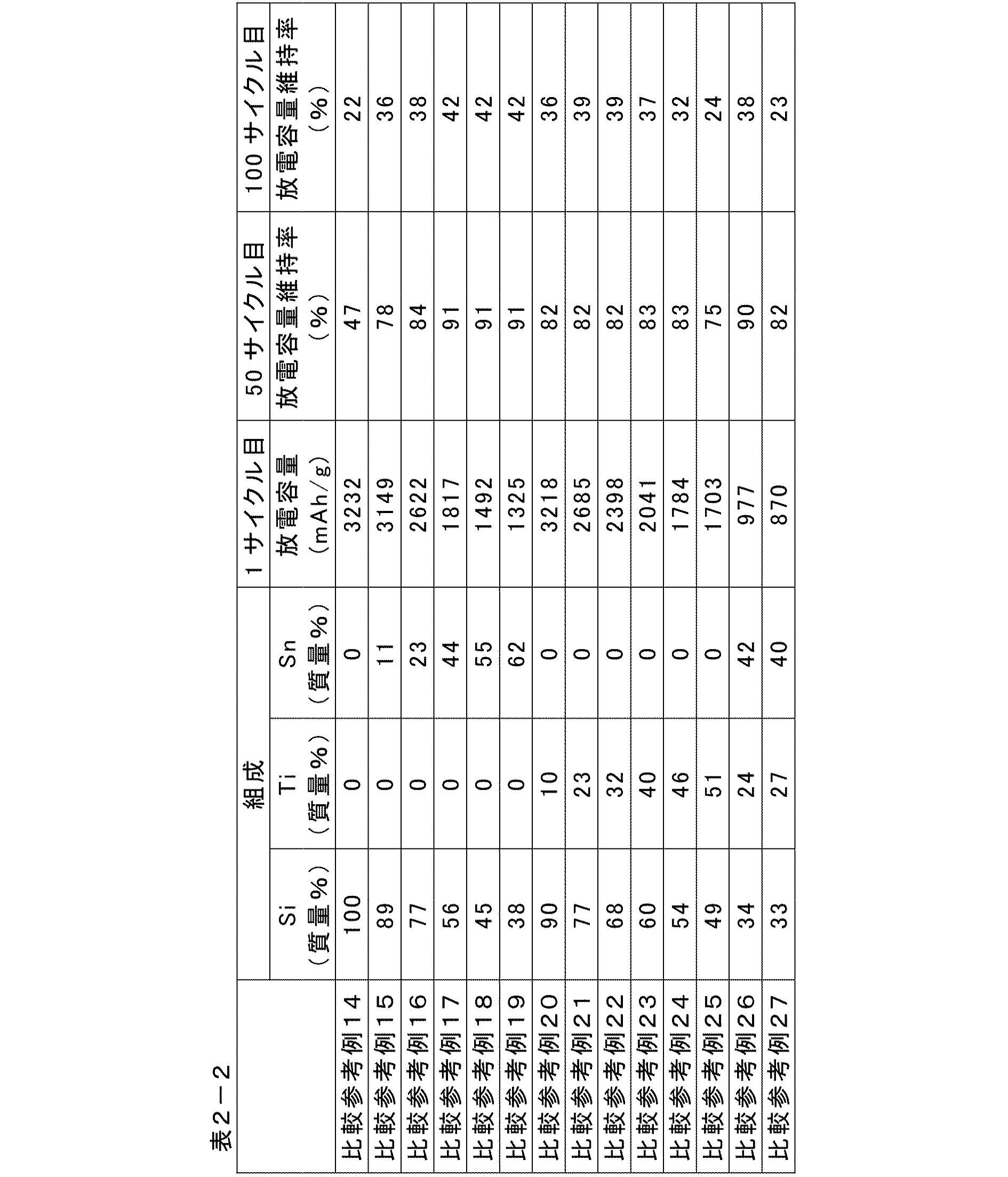
[1]負極の作製
参考例1における(1)および(2)のDC電源の条件を下記のように変更したことを除いては、参考例1と同様の方法で、都合40種の負極サンプルを作製した(参考例45~56および参考比較例28~40)。
Si(純度:4N):直径2インチ、厚さ3mm(厚さ2mmの無酸素銅製バッキングプレート付)
Ti(純度:5N):直径2インチ、厚さ5mm
Zn(純度:4N):直径2インチ、厚さ5mm。
DC電源:Si(185W)、Ti(50~200W)、Zn(30~90W)。
参考例1と同様の方法でCR2032型コインセルを作製した。
50サイクル目の放電容量維持率を下記数式により算出したことを除いては、参考例1と同様の方法で電池の充放電試験を行った。この結果を表3に併せて示す。


参考例48および参考比較例34、37の評価用電極を用いた評価用セル(CR2032型コインセル)につき、[3]と同様の充放電条件で初期サイクルを実施した。初期サイクルの放電過程での電圧(V)に対するdQ/dV曲線を図22に示す。
[Si合金の製造]
Si合金は、メカニカルアロイ法(または、アークプラズマ溶融法)により製造した。具体的には、ドイツ フリッチュ社製遊星ボールミル装置P-6を用いて、ジルコニア製粉砕ポットにジルコニア製粉砕ボールと各合金の各原料粉末を投入し、600rpm、48hかけて合金化させた。
負極活物質である上記で製造したSi合金(Si42Ti7Sn51、粒子径0.3μm)2.76質量部および黒鉛(平均粒子径22μm)89.24質量部と、導電助剤であるアセチレンブラック4質量部と、バインダであるポリイミド4質量部と、を混合し、N-メチルピロリドンに分散させて負極スラリーを得た。次いで、得られた負極スラリーを、厚さ10μmの銅箔よりなる負極集電体の両面にそれぞれ負極活物質層の厚さが30μmとなるように均一に塗布し、真空中で24時間乾燥させて、負極を得た。なお、負極活物質中のSi合金の含有率は、3%である。
正極活物質であるLi1.85Ni0.18Co0.10Mn0.87O3を、特開2012-185913号公報の実施例1(段落0046)に記載の手法により作製した。そして、この正極活物質90質量部と、導電助剤であるアセチレンブラック5質量部と、バインダであるポリフッ化ビニリデン5質量部と、を混合し、N-メチルピロリドンに分散させて正極スラリーを得た。次いで、得られた正極スラリーを、厚さ20μmのアルミニウム箔よりなる正極集電体の両面にそれぞれ正極活物質層の厚さが30μmとなるように均一に塗布し、乾燥させて、正極を得た。
上記で作製した正極と、負極とを対向させ、この間にセパレータ(ポリプロピレン製の微多孔膜、膜厚20μm)を配置した。次いで、負極、セパレータ、および正極の積層体をコインセル(CR2032、材質:ステンレス鋼(SUS316))の底部側に配置した。さらに、正極と負極との間の絶縁性を保つためガスケットを装着し、下記電解液をシリンジにより注入し、スプリング及びスペーサを積層し、コインセルの上部側を重ねあわせ、かしめることにより密閉して、リチウムイオン二次電池を得た。
Si合金を4.6質量部に変更し、黒鉛を87.4質量部に変更したことを除いては、実施例1と同様の方法で負極および電池を作製した。なお、負極活物質中のSi合金の含有率は、5%である。
Si合金を6.44質量部に変更し、黒鉛を85.56質量部に変更したことを除いては、実施例1と同様の方法で負極および電池を作製した。なお、負極活物質中のSi合金の含有率は、7%である。
Si合金を9.2質量部に変更し、黒鉛を82.8質量部に変更したことを除いては、実施例1と同様の方法で負極および電池を作製した。なお、負極活物質中のSi合金の含有率は、10%である。
Si合金を11.04質量部に変更し、黒鉛を80.96質量部に変更したことを除いては、実施例1と同様の方法で負極および電池を作製した。なお、負極活物質中のSi合金の含有率は、12%である。
Si合金を13.8質量部に変更し、黒鉛を78.2質量部に変更したことを除いては、実施例1と同様の方法で負極および電池を作製した。なお、負極活物質中のSi合金の含有率は、15%である。
Si合金を18.4質量部に変更し、黒鉛を73.6質量部に変更したことを除いては、実施例1と同様の方法で負極および電池を作製した。なお、負極活物質中のSi合金の含有率は、20%である。
Si合金を23.0質量部に変更し、黒鉛を69.0質量部に変更したことを除いては、実施例1と同様の方法で負極および電池を作製した。なお、負極活物質中のSi合金の含有率は、25%である。
Si合金を27.6質量部に変更し、黒鉛を64.4質量部に変更したことを除いては、実施例1と同様の方法で負極および電池を作製した。なお、負極活物質中のSi合金の含有率は、30%である。
Si合金を36.8質量部に変更し、黒鉛を55.2質量部に変更したことを除いては、実施例1と同様の方法で負極および電池を作製した。なお、負極活物質中のSi合金の含有率は、40%である。
Si合金を46.0質量部に変更し、黒鉛を46.0質量部に変更したことを除いては、実施例1と同様の方法で負極および電池を作製した。なお、負極活物質中のSi合金の含有率は、50%である。
Si合金を55.2質量部に変更し、黒鉛を36.8質量部に変更したことを除いては、実施例1と同様の方法で負極および電池を作製した。なお、負極活物質中のSi合金の含有率は、60%である。
Si合金を64.4質量部に変更し、黒鉛を27.6質量部に変更したことを除いては、実施例1と同様の方法で負極および電池を作製した。なお、負極活物質中のSi合金の含有率は、70%である。
[サイクル特性の評価]
上記で作製した各リチウムイオン二次電池について以下の方法でサイクル特性評価を行った。各電池について、30℃の雰囲気下、定電流方式(CC、電流:0.1C)で2.0Vまで充電し、10分間休止させた後、定電流(CC、電流:0.1C)で0.01Vまで放電し、放電後10分間休止させた。この充放電過程を1サイクルとし、100サイクルの充放電試験を行い、1サイクル目の放電容量に対する100サイクル目の放電容量の割合(放電容量維持率[%])を求めた。得られた結果を下記の表4および図23に示す。
上記で作製した各リチウムイオン二次電池について以下の方法でサイクル特性評価を行った。各電池について、まず初期充放電として正極の理論容量に対して0.2C相当の電流で、定電流充電後、4.2Vの定電圧充電を合計10時間行い、その後0.2Cの放電電流にて2.7Vまで定電流放電を行った。このときの充放電曲線から電池のエネルギーを算出し、電池質量で除して電池のエネルギー密度を算出した。得られた結果を下記の表4および図23に示す。
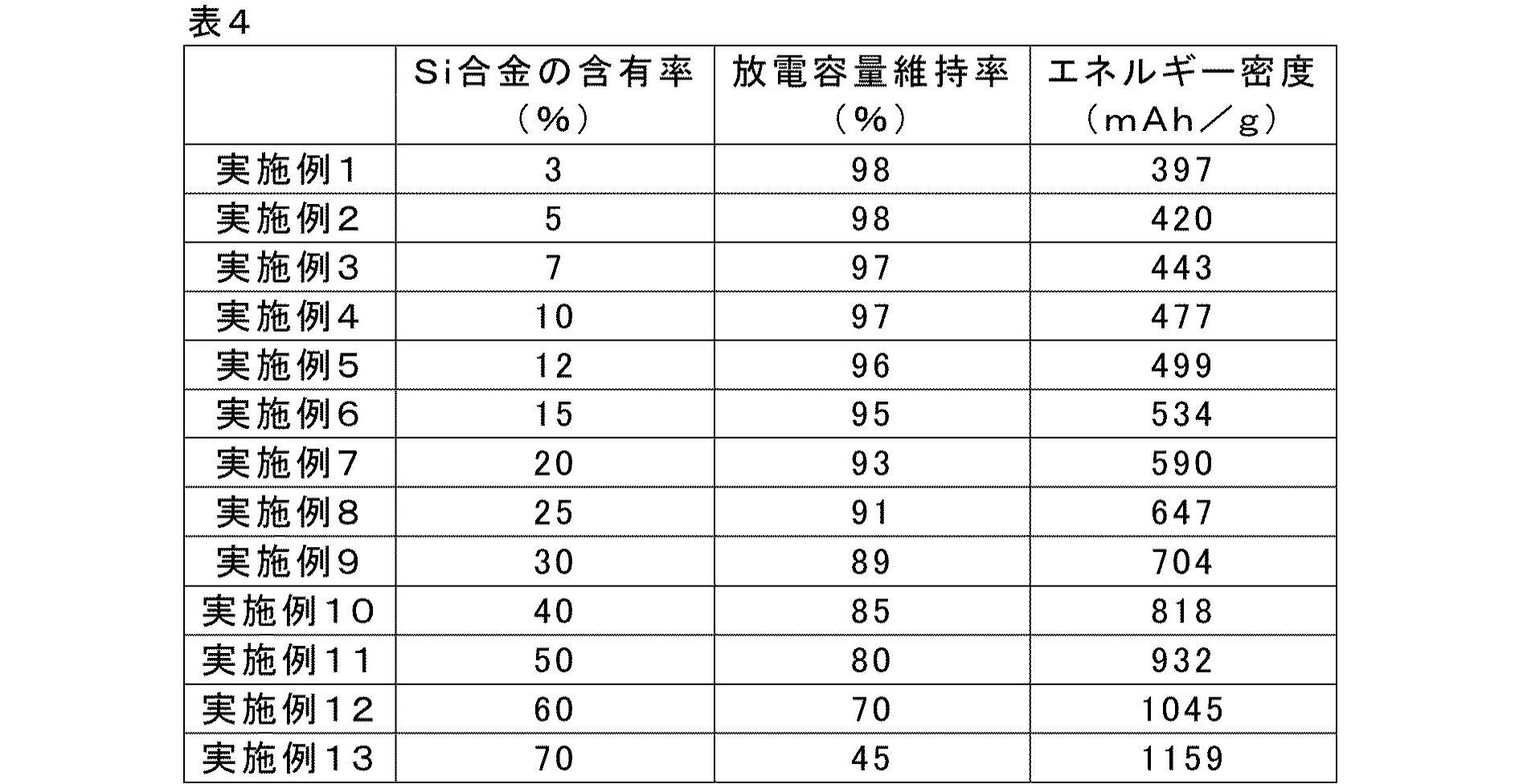
11 正極集電体、
12 負極集電体、
13 正極活物質層、
15 負極活物質層、
17 電解質層、
19 単電池層、
21、57 発電要素、
25、58 正極集電板、
27、59 負極集電板、
29、52 電池外装材(ラミネートフィルム)。
Claims (20)
- 集電体と、前記集電体の表面に配置された負極活物質、導電助剤、およびバインダを含む電極層と、を有する電気デバイス用負極であって、
前記負極活物質が、下記式(1):

Mは、Ge、Sn、Zn、およびこれらの組み合わせからなる群から選択される少なくとも1つの金属であり、
Aは、不可避不純物であり、
x、y、z、およびaは、質量%の値を表し、この際、0<x<100、0<y<100、0<z<100、および0≦a<0.5であり、x+y+z+a=100である。)
で表される合金と、炭素系材料とが混合されてなる、電気デバイス用負極。 - 前記負極活物質中の合金の含有率が、3~70%である、請求項1に記載の電気デバイス用負極。
- 前記負極活物質中の合金の含有率が、30~50%である、請求項2に記載の電気デバイス用負極。
- 前記負極活物質中の合金の含有率が、50~70%である、請求項2に記載の電気デバイス用負極。
- 前記合金の平均粒子径が、前記炭素系材料の平均粒子径よりも小さい、請求項1~4のいずれか1項に記載の電気デバイス用負極。
- 前記Mが、Geであり、
前記xが17以上90未満であり、前記yが10超83未満であり、zが0超73未満である、請求項1~5のいずれか1項に記載の電気デバイス用負極。 - 前記xが77以下であり、前記yが20以上であり、前記zが3以上63以下である、請求項6に記載の電気デバイス用負極。
- 前記yが68以下である、請求項7に記載の電気デバイス用負極。
- 前記xが50以下である、請求項8に記載の電気デバイス用負極。
- 前記xが46以下であり、前記yが51以上、前記zが32以下である、請求項9に記載の電気デバイス用負極。
- 前記MがSnであり、
前記x、y、およびzが、下記数式(1)または(2):

- 前記MがSnであり、
前記x、y、およびzが、下記数式(3)または(4):
- 前記MがSnであり、
前記x、y、およびzが、下記数式(5)または(6):

- 前記MがSnであり、
前記x、y、およびzが、下記数式(7):

- 前記MがZnであり、
前記x、y、およびzが、下記数式(8):

- 前記x、y、およびzが、下記数式(9):

- 前記x、y、およびzが、下記数式(10):

- 前記x、y、およびzが、下記数式(11):

- 前記x、y、およびzが、下記数式(12):

- 請求項1~19のいずれか1項に記載の電気デバイス用負極を含む、電気デバイス。
Priority Applications (5)
| Application Number | Priority Date | Filing Date | Title |
|---|---|---|---|
| KR1020157013092A KR101823214B1 (ko) | 2012-11-22 | 2013-11-19 | 전기 디바이스용 부극, 및 이것을 사용한 전기 디바이스 |
| CN201380061222.8A CN104854734B9 (zh) | 2012-11-22 | 2013-11-19 | 电气设备用负极、及使用其的电气设备 |
| EP13856910.8A EP2924770B1 (en) | 2012-11-22 | 2013-11-19 | Negative electrode for a lithium-ion battery and electrical device provided with same |
| JP2014548571A JP6024760B2 (ja) | 2012-11-22 | 2013-11-19 | リチウムイオン二次電池用負極、及びこれを用いたリチウムイオン二次電池 |
| US14/443,572 US20150303455A1 (en) | 2012-11-22 | 2013-11-19 | Negative electrode for electric device and electric device using the same |
Applications Claiming Priority (2)
| Application Number | Priority Date | Filing Date | Title |
|---|---|---|---|
| JP2012256893 | 2012-11-22 | ||
| JP2012-256893 | 2012-11-22 |
Publications (1)
| Publication Number | Publication Date |
|---|---|
| WO2014080893A1 true WO2014080893A1 (ja) | 2014-05-30 |
Family
ID=50776074
Family Applications (1)
| Application Number | Title | Priority Date | Filing Date |
|---|---|---|---|
| PCT/JP2013/081144 Ceased WO2014080893A1 (ja) | 2012-11-22 | 2013-11-19 | 電気デバイス用負極、及びこれを用いた電気デバイス |
Country Status (6)
| Country | Link |
|---|---|
| US (1) | US20150303455A1 (ja) |
| EP (1) | EP2924770B1 (ja) |
| JP (1) | JP6024760B2 (ja) |
| KR (1) | KR101823214B1 (ja) |
| CN (1) | CN104854734B9 (ja) |
| WO (1) | WO2014080893A1 (ja) |
Cited By (1)
| Publication number | Priority date | Publication date | Assignee | Title |
|---|---|---|---|---|
| JP2017091820A (ja) * | 2015-11-10 | 2017-05-25 | 日産自動車株式会社 | 電気デバイス用負極活物質、およびこれを用いた電気デバイス |
Families Citing this family (7)
| Publication number | Priority date | Publication date | Assignee | Title |
|---|---|---|---|---|
| JP5751448B2 (ja) | 2011-05-25 | 2015-07-22 | 日産自動車株式会社 | リチウムイオン二次電池用負極活物質 |
| KR20180031067A (ko) | 2012-11-22 | 2018-03-27 | 닛산 지도우샤 가부시키가이샤 | 전기 디바이스용 부극, 및 이것을 사용한 전기 디바이스 |
| WO2014080886A1 (ja) | 2012-11-22 | 2014-05-30 | 日産自動車株式会社 | 電気デバイス用負極、及びこれを用いた電気デバイス |
| CN105934847B (zh) | 2014-01-24 | 2019-11-05 | 日产自动车株式会社 | 电器件 |
| CN105934846B (zh) | 2014-01-24 | 2019-06-28 | 日产自动车株式会社 | 电器件 |
| CN109075377B (zh) * | 2016-04-28 | 2020-08-25 | 远景Aesc日本有限公司 | 非水电解质二次电池 |
| JP6560447B2 (ja) * | 2016-04-28 | 2019-08-14 | 株式会社エンビジョンAescジャパン | 非水電解質二次電池 |
Citations (12)
| Publication number | Priority date | Publication date | Assignee | Title |
|---|---|---|---|---|
| JP2000299108A (ja) * | 1999-04-14 | 2000-10-24 | Sony Corp | 非水電解質電池 |
| JP2003331826A (ja) * | 2002-05-08 | 2003-11-21 | Sony Corp | 非水電解質電池 |
| JP2004185984A (ja) * | 2002-12-03 | 2004-07-02 | Osaka Gas Co Ltd | リチウム二次電池用負極材及びそれを用いたリチウム二次電池 |
| JP2004349016A (ja) * | 2003-05-20 | 2004-12-09 | Matsushita Electric Ind Co Ltd | 非水電解質二次電池の充放電方法 |
| JP2007305424A (ja) * | 2006-05-11 | 2007-11-22 | Sony Corp | 負極活物質およびそれを用いた電池 |
| JP2009517850A (ja) | 2005-12-01 | 2009-04-30 | スリーエム イノベイティブ プロパティズ カンパニー | ケイ素含有量が高いアモルファス合金に基づく電極組成物 |
| JP2010135336A (ja) * | 2003-03-26 | 2010-06-17 | Canon Inc | リチウム二次電池用の電極材料、該電極材料を有する電極構造体、及び該電極構造体を有する二次電池 |
| WO2011065503A1 (ja) * | 2009-11-27 | 2011-06-03 | 日産自動車株式会社 | 電気デバイス用Si合金負極活物質 |
| JP2012185913A (ja) | 2011-03-03 | 2012-09-27 | Nissan Motor Co Ltd | リチウムイオン二次電池用正極活物質、リチウムイオン二次電池用正極及びリチウムイオン二次電池 |
| WO2012161190A1 (ja) * | 2011-05-25 | 2012-11-29 | 日産自動車株式会社 | 電気デバイス用負極活物質、電気デバイス用負極及び電気デバイス |
| WO2013099441A1 (ja) * | 2011-12-27 | 2013-07-04 | 日産自動車株式会社 | 電気デバイス用負極活物質 |
| JP2013161785A (ja) * | 2012-02-07 | 2013-08-19 | Samsung Sdi Co Ltd | リチウム2次電池用負極活物質、その製造方法、およびこれを含むリチウム2次電池 |
Family Cites Families (7)
| Publication number | Priority date | Publication date | Assignee | Title |
|---|---|---|---|---|
| CA2305837C (en) * | 1999-04-14 | 2011-05-31 | Sony Corporation | Material for negative electrode and nonaqueous-electrolyte battery incorporating the same |
| JP4366101B2 (ja) * | 2003-03-31 | 2009-11-18 | キヤノン株式会社 | リチウム二次電池 |
| US7635540B2 (en) * | 2004-11-15 | 2009-12-22 | Panasonic Corporation | Negative electrode for non-aqueous electrolyte secondary battery and non-aqueous electrolyte secondary battery comprising the same |
| JP2007149604A (ja) * | 2005-11-30 | 2007-06-14 | Sanyo Electric Co Ltd | リチウム二次電池用負極及びリチウム二次電池 |
| US9012073B2 (en) * | 2008-11-11 | 2015-04-21 | Envia Systems, Inc. | Composite compositions, negative electrodes with composite compositions and corresponding batteries |
| US9876221B2 (en) * | 2010-05-14 | 2018-01-23 | Samsung Sdi Co., Ltd. | Negative active material for rechargeable lithium battery and rechargeable lithium battery including same |
| KR20130037091A (ko) * | 2011-10-05 | 2013-04-15 | 삼성에스디아이 주식회사 | 음극 활물질 및 이를 채용한 리튬 전지 |
-
2013
- 2013-11-19 WO PCT/JP2013/081144 patent/WO2014080893A1/ja not_active Ceased
- 2013-11-19 EP EP13856910.8A patent/EP2924770B1/en active Active
- 2013-11-19 KR KR1020157013092A patent/KR101823214B1/ko not_active Expired - Fee Related
- 2013-11-19 US US14/443,572 patent/US20150303455A1/en not_active Abandoned
- 2013-11-19 JP JP2014548571A patent/JP6024760B2/ja active Active
- 2013-11-19 CN CN201380061222.8A patent/CN104854734B9/zh active Active
Patent Citations (12)
| Publication number | Priority date | Publication date | Assignee | Title |
|---|---|---|---|---|
| JP2000299108A (ja) * | 1999-04-14 | 2000-10-24 | Sony Corp | 非水電解質電池 |
| JP2003331826A (ja) * | 2002-05-08 | 2003-11-21 | Sony Corp | 非水電解質電池 |
| JP2004185984A (ja) * | 2002-12-03 | 2004-07-02 | Osaka Gas Co Ltd | リチウム二次電池用負極材及びそれを用いたリチウム二次電池 |
| JP2010135336A (ja) * | 2003-03-26 | 2010-06-17 | Canon Inc | リチウム二次電池用の電極材料、該電極材料を有する電極構造体、及び該電極構造体を有する二次電池 |
| JP2004349016A (ja) * | 2003-05-20 | 2004-12-09 | Matsushita Electric Ind Co Ltd | 非水電解質二次電池の充放電方法 |
| JP2009517850A (ja) | 2005-12-01 | 2009-04-30 | スリーエム イノベイティブ プロパティズ カンパニー | ケイ素含有量が高いアモルファス合金に基づく電極組成物 |
| JP2007305424A (ja) * | 2006-05-11 | 2007-11-22 | Sony Corp | 負極活物質およびそれを用いた電池 |
| WO2011065503A1 (ja) * | 2009-11-27 | 2011-06-03 | 日産自動車株式会社 | 電気デバイス用Si合金負極活物質 |
| JP2012185913A (ja) | 2011-03-03 | 2012-09-27 | Nissan Motor Co Ltd | リチウムイオン二次電池用正極活物質、リチウムイオン二次電池用正極及びリチウムイオン二次電池 |
| WO2012161190A1 (ja) * | 2011-05-25 | 2012-11-29 | 日産自動車株式会社 | 電気デバイス用負極活物質、電気デバイス用負極及び電気デバイス |
| WO2013099441A1 (ja) * | 2011-12-27 | 2013-07-04 | 日産自動車株式会社 | 電気デバイス用負極活物質 |
| JP2013161785A (ja) * | 2012-02-07 | 2013-08-19 | Samsung Sdi Co Ltd | リチウム2次電池用負極活物質、その製造方法、およびこれを含むリチウム2次電池 |
Non-Patent Citations (1)
| Title |
|---|
| See also references of EP2924770A4 |
Cited By (1)
| Publication number | Priority date | Publication date | Assignee | Title |
|---|---|---|---|---|
| JP2017091820A (ja) * | 2015-11-10 | 2017-05-25 | 日産自動車株式会社 | 電気デバイス用負極活物質、およびこれを用いた電気デバイス |
Also Published As
| Publication number | Publication date |
|---|---|
| KR20150074098A (ko) | 2015-07-01 |
| EP2924770A1 (en) | 2015-09-30 |
| EP2924770B1 (en) | 2018-05-02 |
| CN104854734B9 (zh) | 2018-01-30 |
| JP6024760B2 (ja) | 2016-11-16 |
| EP2924770A4 (en) | 2015-11-04 |
| JPWO2014080893A1 (ja) | 2017-01-05 |
| CN104854734B (zh) | 2017-12-19 |
| KR101823214B1 (ko) | 2018-01-29 |
| US20150303455A1 (en) | 2015-10-22 |
| CN104854734A (zh) | 2015-08-19 |
Similar Documents
| Publication | Publication Date | Title |
|---|---|---|
| JP6020591B2 (ja) | リチウムイオン二次電池用負極、及びこれを用いたリチウムイオン二次電池 | |
| JP5387690B2 (ja) | 電気デバイス用Si合金負極活物質 | |
| JP5333605B2 (ja) | 電気デバイス用Si合金負極活物質 | |
| JP6040996B2 (ja) | リチウムイオン二次電池用負極、及びこれを用いたリチウムイオン二次電池 | |
| JP6032288B2 (ja) | 電気デバイス用負極、及びこれを用いた電気デバイス | |
| JP6024760B2 (ja) | リチウムイオン二次電池用負極、及びこれを用いたリチウムイオン二次電池 | |
| JPWO2014080895A1 (ja) | リチウムイオン二次電池用負極、及びこれを用いたリチウムイオン二次電池 | |
| JP6052299B2 (ja) | 電気デバイス用負極、及びこれを用いた電気デバイス | |
| WO2012070306A1 (ja) | 電気デバイス用Si合金負極活物質 | |
| JP6040997B2 (ja) | リチウムイオン二次電池用負極、及びこれを用いたリチウムイオン二次電池 | |
| WO2014080885A1 (ja) | 電気デバイス用負極、及びこれを用いた電気デバイス | |
| WO2014199785A1 (ja) | 電気デバイス用負極活物質、およびこれを用いた電気デバイス | |
| JP6028811B2 (ja) | リチウムイオン二次電池用負極、及びこれを用いたリチウムイオン二次電池 | |
| JP6015769B2 (ja) | リチウムイオン二次電池用負極、及びこれを用いたリチウムイオン二次電池 | |
| JP6052298B2 (ja) | 電気デバイス用負極、及びこれを用いた電気デバイス | |
| JP6040994B2 (ja) | リチウムイオン二次電池用負極、及びこれを用いたリチウムイオン二次電池 | |
| WO2014080900A1 (ja) | 電気デバイス用負極、及びこれを用いた電気デバイス | |
| WO2014080898A1 (ja) | 電気デバイス用負極、及びこれを用いた電気デバイス | |
| WO2014199783A1 (ja) | 電気デバイス用負極活物質、およびこれを用いた電気デバイス | |
| JPWO2014199781A1 (ja) | 電気デバイス用負極活物質、およびこれを用いた電気デバイス | |
| WO2014080903A1 (ja) | 電気デバイス用負極、及びこれを用いた電気デバイス | |
| WO2014080902A1 (ja) | 電気デバイス用負極、及びこれを用いた電気デバイス |
Legal Events
| Date | Code | Title | Description |
|---|---|---|---|
| 121 | Ep: the epo has been informed by wipo that ep was designated in this application |
Ref document number: 13856910 Country of ref document: EP Kind code of ref document: A1 |
|
| DPE2 | Request for preliminary examination filed before expiration of 19th month from priority date (pct application filed from 20040101) | ||
| WWE | Wipo information: entry into national phase |
Ref document number: 2013856910 Country of ref document: EP |
|
| WWE | Wipo information: entry into national phase |
Ref document number: 14443572 Country of ref document: US |
|
| ENP | Entry into the national phase |
Ref document number: 20157013092 Country of ref document: KR Kind code of ref document: A |
|
| ENP | Entry into the national phase |
Ref document number: 2014548571 Country of ref document: JP Kind code of ref document: A |
|
| NENP | Non-entry into the national phase |
Ref country code: DE |