WO2014083907A1 - ボールジョイント - Google Patents
ボールジョイント Download PDFInfo
- Publication number
- WO2014083907A1 WO2014083907A1 PCT/JP2013/073788 JP2013073788W WO2014083907A1 WO 2014083907 A1 WO2014083907 A1 WO 2014083907A1 JP 2013073788 W JP2013073788 W JP 2013073788W WO 2014083907 A1 WO2014083907 A1 WO 2014083907A1
- Authority
- WO
- WIPO (PCT)
- Prior art keywords
- ball
- sheet
- socket
- seat
- cover
- Prior art date
- Legal status (The legal status is an assumption and is not a legal conclusion. Google has not performed a legal analysis and makes no representation as to the accuracy of the status listed.)
- Ceased
Links
Images

Classifications
-
- F—MECHANICAL ENGINEERING; LIGHTING; HEATING; WEAPONS; BLASTING
- F16—ENGINEERING ELEMENTS AND UNITS; GENERAL MEASURES FOR PRODUCING AND MAINTAINING EFFECTIVE FUNCTIONING OF MACHINES OR INSTALLATIONS; THERMAL INSULATION IN GENERAL
- F16C—SHAFTS; FLEXIBLE SHAFTS; ELEMENTS OR CRANKSHAFT MECHANISMS; ROTARY BODIES OTHER THAN GEARING ELEMENTS; BEARINGS
- F16C11/00—Pivots; Pivotal connections
- F16C11/04—Pivotal connections
- F16C11/06—Ball-joints; Other joints having more than one degree of angular freedom, i.e. universal joints
- F16C11/0619—Ball-joints; Other joints having more than one degree of angular freedom, i.e. universal joints the female part comprising a blind socket receiving the male part
- F16C11/0623—Construction or details of the socket member
- F16C11/0628—Construction or details of the socket member with linings
- F16C11/0633—Construction or details of the socket member with linings the linings being made of plastics
- F16C11/0638—Construction or details of the socket member with linings the linings being made of plastics characterised by geometrical details
-
- F—MECHANICAL ENGINEERING; LIGHTING; HEATING; WEAPONS; BLASTING
- F16—ENGINEERING ELEMENTS AND UNITS; GENERAL MEASURES FOR PRODUCING AND MAINTAINING EFFECTIVE FUNCTIONING OF MACHINES OR INSTALLATIONS; THERMAL INSULATION IN GENERAL
- F16C—SHAFTS; FLEXIBLE SHAFTS; ELEMENTS OR CRANKSHAFT MECHANISMS; ROTARY BODIES OTHER THAN GEARING ELEMENTS; BEARINGS
- F16C11/00—Pivots; Pivotal connections
- F16C11/04—Pivotal connections
- F16C11/06—Ball-joints; Other joints having more than one degree of angular freedom, i.e. universal joints
- F16C11/0614—Ball-joints; Other joints having more than one degree of angular freedom, i.e. universal joints the female part of the joint being open on two sides
-
- F—MECHANICAL ENGINEERING; LIGHTING; HEATING; WEAPONS; BLASTING
- F16—ENGINEERING ELEMENTS AND UNITS; GENERAL MEASURES FOR PRODUCING AND MAINTAINING EFFECTIVE FUNCTIONING OF MACHINES OR INSTALLATIONS; THERMAL INSULATION IN GENERAL
- F16C—SHAFTS; FLEXIBLE SHAFTS; ELEMENTS OR CRANKSHAFT MECHANISMS; ROTARY BODIES OTHER THAN GEARING ELEMENTS; BEARINGS
- F16C11/00—Pivots; Pivotal connections
- F16C11/04—Pivotal connections
- F16C11/06—Ball-joints; Other joints having more than one degree of angular freedom, i.e. universal joints
- F16C11/0666—Sealing means between the socket and the inner member shaft
- F16C11/0671—Sealing means between the socket and the inner member shaft allowing operative relative movement of joint parts due to flexing of the sealing means
Definitions
- the present invention relates to a ball joint in which a resin bearing sheet that slidably accommodates a spherical ball portion formed at the tip of a shaft-like stud portion is held in a metal socket.
- a ball joint is used in a suspension mechanism (suspension device) and a steering mechanism (steering device) in a vehicle such as an automobile in order to movably connect shaft-shaped components to each other.
- a substantially spherical ball portion formed mainly at the tip of a shaft-shaped ball stud slides in a metal socket via a resin ball seat (also referred to as a “bearing seat”). It is configured to be held in a free state.
- the ball joint is provided with a dust cover so as to cover at least the opening of the ball seat in order to prevent foreign matter such as water droplets and dust from entering the socket in which the ball portion slides.
- Patent Document 1 discloses a ball joint in which a rubber dust cover is attached to the outside of an opening in a resin ball sheet exposed from a socket.
- the present invention has been made to address the above problems, and an object of the present invention is to provide a ball joint that can ensure the strength against the pulling-out force and the punching-out force of the ball portion while ensuring the sealing performance of the dust cover. It is in.
- the present invention is characterized by a resin-made bearing seat that slidably accommodates a spherical ball portion formed at a tip portion of a shaft-shaped stud portion, and a cylindrical shape that holds the bearing seat.
- a ball joint including a metal socket having a cup-shaped seat accommodating portion and a dust cover that covers the seat opening portion of the bearing seat through which the stud portion penetrates and prevents foreign matter from entering the bearing seat.
- the socket is formed such that the seat accommodating portion extends to the stud portion side from the ball center of the ball portion, and the bearing seat has a covering portion that covers the outer peripheral portion on the opening side of the seat accommodating portion,
- a ball joint characterized in that the dust cover is attached to the cover.
- the ball joint is formed such that the seat accommodating portion of the socket extends to the stud portion side from the ball center of the ball portion, and the bearing seat is an opening of the seat accommodating portion. It has a cover part that covers up to the outer peripheral part on the part side, and a dust cover is attached to this cover part. That is, in the ball joint according to the present invention, since the dust cover is attached to the resin ball sheet, it is easy to ensure the sealing performance as compared with the case where the dust cover is attached to the metal socket.
- the ball joint is formed by extending a metal socket inside the cover portion of the ball seat to which the dust cover is attached, the ball joint accommodates the deformation of the cover portion due to the attachment of the dust cover and the ball portion in the ball seat.
- the deformation of the portion can be prevented, and the deformation of the portion accommodating the ball portion due to the pulling force and the punching force acting on the ball portion can be suppressed.
- the ball joint can ensure the strength against the pulling-out force and the punching-out force of the ball part while ensuring the sealing performance of the dust cover.
- the ball joint has a tapered shape in which an outer peripheral portion on the opening side of the seat accommodating portion in the socket and an inner peripheral portion of the cover portion in the bearing seat facing the outer peripheral portion correspond to each other. It is in being formed.
- the ball joint is configured such that the outer peripheral portion on the opening side of the seat accommodating portion of the socket and the inner peripheral portion of the cover portion of the ball sheet facing the outer peripheral portion are tapered. Since it is formed in a shape, it is possible to ensure a long distance facing each other and to further ensure a sealing property.
- the socket is formed to extend to the stud side from the sliding surface on which the ball portion slides relative to the bearing seat.
- the ball joint is formed so that the socket extends to the stud side from the sliding surface on which the ball portion slides relative to the bearing seat. It is possible to more effectively suppress the deformation of the portion that accommodates the ball portion due to the pulling force and the punching force acting on the.
- another feature of the present invention is that, in the ball joint, the bearing seat is fixed to the socket in a state where an end portion opposite to the seat opening is exposed from the socket.
- the ball joint is configured to be fixed to the socket in a state where the end of the bearing seat opposite to the seat opening is exposed from the socket. That is, the ball joint is a ball joint in which the ball seat is fixed to the socket on the opposite side of the seat opening. Since only the covering portion of the ball seat becomes longer, it is possible to effectively prevent water from entering the ball seat fixing portion.
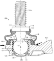
- FIG. 1 is a sectional view schematically showing a longitudinal section of a ball joint 100 according to the present invention. Note that each drawing referred to in the present specification is schematically represented by exaggerating some of the components in order to facilitate understanding of the present invention. For this reason, the dimension, ratio, etc. between each component may differ.
- the ball joint 100 is a joint member that connects components to each other while allowing a change in angle between the components in a suspension mechanism (suspension device) or a steering mechanism (steering device) employed in a vehicle such as an automobile. is there.
- the ball joint 100 shown in FIG. 1 is one of the ball joints provided at both ends of a stabilizer link (not shown) in the suspension mechanism.
- the ball joint 100 is mainly composed of a ball stud 110, a socket 120, a ball seat 130, and a dust cover 140.
- the ball stud 110 is made of a steel material, and is formed in a substantially spherical shape via a flange portion 112 and a constricted portion 113 on one end side of the stud portion 111 formed in a shaft shape.
- a ball portion 114 is provided.
- the stud portion 111 is a portion for connecting the ball joint 100 to a component in a steering mechanism (not shown), and is configured by forming a male screw 111a at the end opposite to the ball portion 114.
- the ball portion 114 is a portion that slides in the ball sheet 130, and the sliding surface 114 a that slides with respect to the ball sheet 130 smoothly slides with respect to the inner peripheral surface of the ball sheet 130. It is formed in a smooth spherical shape.
- the socket 120 is formed by casting a metal material such as a non-ferrous metal or a steel material, and extends in a horizontal direction from a sheet accommodating portion 121 formed in a substantially cylindrical shape and an outer peripheral portion of the sheet accommodating portion 121.
- the connecting portion 124 is formed.
- the socket 120 is made of an aluminum alloy, but may be configured using other materials, for example, a magnesium material or a zinc material.
- the sheet accommodating portion 121 is formed of a cylindrical body, and is a portion that accommodates and holds the ball portion 114 of the ball stud 110 via the ball seat 130 on the inner peripheral portion of the cylindrical body.
- the sheet accommodating portion 121 is formed such that the end portion side through which the stud portion 111 passes extends to the stud portion 111 side from the ball center O of the ball portion 114. More specifically, the upper end portion in the figure of the seat accommodating portion 121 is formed to extend to a position facing a portion between the sliding surface 114 a of the ball portion 114 and the constricted portion 113.
- an outer peripheral portion of the end portion on the stud portion 111 side in the sheet accommodating portion 121 is formed with a tapered sheet facing portion 122 having a diameter that decreases toward the tip portion, and is illustrated horizontally on the root side of the sheet facing portion 122.
- Cover support portions 123 projecting in the direction are formed.
- one end (left side in the figure) of the connecting part 124 is connected to the sheet storage part 121, and the other end (right side in the figure) is connected to an arm part in a stabilizer link (not shown).
- a ball seat 130 as a bearing seat is provided on the inner peripheral portion of the seat accommodating portion 121 in the socket 120 between the ball portion 114 of the ball stud 110 held on the inner peripheral portion.
- the ball seat 130 is a resin part that slidably holds the ball portion 114 of the ball stud 110, and is formed in a bottomed cylindrical shape having an inner peripheral surface along the spherical surface of the sliding surface 114a of the ball portion 114.
- the ball seat 130 has a cover 133 formed outside the seat opening 132 in the ball accommodating portion 131 formed in a spherical shape corresponding to the sliding surface 114 a of the ball portion 114 of the ball stud 110.
- a fixed portion 134 is formed by projecting in a cylindrical shape on the outer peripheral portion on the bottom side of the ball housing portion 131.
- the cover part 133 is formed by folding back the sheet opening part 132 of the ball storage part 131 so as to cover the outer peripheral part of the opening part of the sheet storage part 121 in the socket 120, that is, the sheet facing part 122. More specifically, the cover portion 133 is formed to project radially outward from the seat opening 132 in the ball housing portion 131, and a part of the projecting portion is formed as a cover support portion 123 of the socket 120. It is formed in a ring shape with a length that reaches the cover support portion 123 toward the side.
- the inner peripheral portion of the cover portion 133 that faces the sheet facing portion 122 is formed in a tapered shape corresponding to the tapered shape of the sheet facing portion 122 and is in contact with the sheet facing portion 122.
- the outer peripheral portion of the cover portion 133 is formed parallel to the axial direction of the ball stud 110 (the vertical direction in the drawing).
- the fixing part 134 is a part for fixing the ball sheet 130 together with the cover part 133 to the sheet accommodating part 121 of the socket 120.
- the fixing portion 134 is formed in a straight shape when the ball sheet 130 is formed, and is deformed radially outward by caulking processing by heating when fixing the ball seat 130 to the seat accommodating portion 121.
- the resin constituting the ball sheet 130 is a synthetic resin material such as polyether ether ketone resin (PEEK), polyimide resin (PI), polyacetal resin (POM), polyvinyl chloride resin (PVC), polyurethane resin (PUR). ), Polycarbonate resin (PC), polystyrene resin (PS), nylon resin (PA-6T, 9T) or polypropylene (PP).
- PEEK polyether ether ketone resin
- PI polyimide resin
- POM polyacetal resin
- PVC polyvinyl chloride resin
- PUR polyurethane resin
- PC Polycarbonate resin
- PS polystyrene resin
- nylon resin PA-6T, 9T
- PP polypropylene
- a dust cover 140 is provided on the outer periphery of the cover part 133 of the ball sheet 130 so as to cover the upper part of the ball sheet 130 and the ball part 114 of the ball stud 110 accommodated in the ball accommodation part 131 of the ball sheet 130. ing.
- the dust cover 140 is made of an elastically deformable rubber material, a soft synthetic resin material, or the like, and is formed in a substantially cylindrical shape in which a central portion is expanded.
- the stud portion 111 of the ball stud 110 is inserted into one (upper side in the drawing), and the portion immediately below the flange portion 112 of the stud portion 111 is fixed by an elastic force.
- the other opening (lower side in the figure) of the dust cover 140 is fixed by the circlip 141 in a state of being fitted into the outer peripheral portion of the cover portion 133. As a result, entry of foreign matter into the ball seat 130 is prevented.
- the worker prepares a ball stud 110, a socket 120, and a ball seat 130, which are parts constituting the ball joint 100, respectively.
- the socket 120 is formed by various other forming processes such as casting such as aluminum die casting and forging of steel.
- the fixing portion 134 of the ball seat 130 is formed in a straight cylindrical shape that can pass through the seat accommodating portion 121 of the socket 120.
- the operator press-fits the ball portion 114 of the ball stud 110 into the ball accommodating portion 131 of the ball seat 130 and fits it. In this case, the operator press-fits the ball portion 114 in a state where grease (not shown) is applied in the ball housing portion 131.
- the worker fixes the ball sheet 130 containing the ball part 114 in the sheet containing part 121 of the socket 120.
- the operator inserts the ball sheet 130 containing the ball part 114 from one (upper side in the drawing) opening in the sheet containing part 121 of the socket 120.
- the cover part 133 of the ball seat 130 is hooked on the upper end part of the sheet storage part 121 in the state of covering the upper end part and the outer peripheral part (seat facing part 121).
- the fixing portion 134 of the ball seat 130 protrudes from the other (lower side in the drawing) opening of the seat housing portion 121.
- the operator softens the fixing portion 134 of the ball seat 130 by heating (for example, ultrasonic caulking) and plastically deforms the outer side in the radial direction to move the fixing portion 134 to the other side (the lower side in the drawing). ). Thereby, the worker can fix the ball seat 130 to the seat accommodating portion 121 of the socket 120.
- the worker attaches the dust cover 140 to the ball sheet 130 fixed to the socket 120. Specifically, after the operator prepares the dust cover 140, the operator inserts one end (upper side in the figure) of the dust cover 140 into the outer periphery of the ball stud 110 and the other end (lower side in the figure) of the dust cover 140. The edge part of the side) is fitted into the outer peripheral part of the cover part 133 in the ball seat 130. Then, the operator fixes the dust cover 140 to the ball sheet 130 by fitting the circlip 141 into the dust cover 140 fitted into the cover portion 133 of the ball sheet 130. Thereby, the ball joint 100 is completed.
- the ball joint 100 is a device that maintains the running stability and steering stability of the vehicle by attenuating vibrations from the road surface and grounding the wheels to the road surface.
- the ball joint 100 supports the load from the vehicle while rotating or swinging the ball stud 110 in a certain direction in the suspension mechanism.
- the ball joint 100 mounted on a vehicle may splash water on the boundary between the dust cover 140 and the socket 120 when the vehicle is traveling (see arrows in the figure).
- the dust joint 140 since the dust joint 140 is attached to the resin ball sheet 130, the ball joint 100 has high adhesion and effectively prevents water from entering the dust cover 140 and the ball sheet 130. The performance can be fully exhibited.
- the ball joint 100 mounted on the vehicle may splash water on the boundary portion between the fixed portion 134 and the socket 120 in the ball seat 130 when the vehicle travels (see arrows in the figure).
- the ball joint 100 is formed such that the path where the ball sheet 130 and the socket 120 face each other is bent by the cover part 133 of the ball sheet 130 and the length of the same surface is increased by the length of the cover part 133.
- the dust cover 140 is attached to the resin ball sheet 130, water from the fixing portion 134 is effectively prevented.
- a pulling force and a pulling force may be applied to the ball portion 114 of the ball stud 120 depending on the traveling of the vehicle.
- the pulling force is a force acting in the axial direction of the ball stud 120 to pull out the ball portion 114 from the ball seat 130
- the pulling force is the ball portion 114 in the ball housing portion 131. This is the force with which the pulling force acts while sliding.
- the ball accommodating portion 131 in the ball seat 130 tends to deform in a direction in which the seat opening 132 expands due to the compression by the ball portion 114, but the sheet accommodating portion 121 of the socket 120 is outside the seat opening 132. Since it is formed, deformation is suppressed. Thereby, the ball joint 100 prevents the ball portion 114 of the ball stud 110 from coming out of the ball accommodating portion 131 of the ball seat 130 when the vehicle is traveling.
- the ball joint 100 is formed such that the seat accommodating portion 121 of the socket 120 extends to the stud portion 111 side of the ball center O of the ball portion 114.
- the ball seat 130 as a bearing seat has a cover portion 133 that covers the outer peripheral portion on the opening side of the seat accommodating portion 121, and the dust cover 140 is attached to the cover portion 133. . That is, in the ball joint 100 according to the present invention, since the dust cover 140 is attached to the resin ball sheet 130, it is easy to ensure the sealing performance as compared with the case where the dust cover 140 is attached to the metal socket 120. .
- the ball joint 100 is formed by extending the metal socket 120 inside the cover part 133 of the ball sheet 130 to which the dust cover 140 is attached, the deformation of the cover part 133 due to the attachment of the dust cover 140 and the ball The deformation of the portion of the seat 130 that accommodates the ball portion 114 can be prevented, and the deformation of the portion of the seat 130 that accommodates the ball portion 114 due to the pulling force and punching force acting on the ball portion 114 can also be suppressed. As a result, the ball joint 100 can ensure the strength against the pulling force and the punching force of the ball portion 114 while ensuring the sealing performance of the dust cover 140.
- the upper end of the sheet accommodating portion 121 in the socket 120 is formed so as to extend to a position facing the portion between the sliding surface 114 a of the ball portion 114 and the constricted portion 113. .
- the ball joint 100 can prevent the ball portion 114 from coming off by preventing the ball housing portion 131 from being deformed by the pulling force or the punching force acting on the ball portion 114.
- the end of the seat accommodating portion 121 of the socket 120 on the side of the stud portion 111 is the ball center O of the ball portion 114, in other words, the equator of the ball portion 114 where the ball portion 114 projects most to the ball accommodating portion 131 side.
- the end portion on the stud portion 111 side of the seat accommodating portion 121 in the socket 120 is preferably formed to extend to the stud portion 111 side from the sliding surface 114a of the ball portion 114, and in this case, the sliding surface 114a.
- the constricted portion 113 are more preferable.
- the equator portion of the ball portion 114 is a portion where a plane passing through the ball center O of the ball portion 114 and orthogonal to the axis of the ball stud 110 intersects the surface of the ball portion 114.
- the ball joint 100 corresponds to the outer peripheral portion of the socket 120 on the opening side of the seat accommodating portion 121 and the inner peripheral portion of the cover portion 133 of the ball sheet 130 facing the outer peripheral portion. Tapered shape was formed. However, the outer peripheral portion on the opening side of the seat accommodating portion 121 in the socket 120 and the inner peripheral portion of the cover portion 133 in the ball sheet 130 facing the outer peripheral portion only need to be configured with surfaces facing each other. You may form mutually straight.
- the outer peripheral portion of the socket 120 on the opening side of the sheet accommodating portion 121 and the inner peripheral portion of the cover portion 133 of the ball sheet 130 facing the outer peripheral portion may be configured to contact each other.
- a slight gap may be provided between the two so as to be opposed to each other. Accordingly, when the socket 120 is configured so that the outer peripheral portion on the opening side of the sheet accommodating portion 121 and the inner peripheral portion of the cover portion 133 in the ball sheet 130 facing the outer peripheral portion are in contact with each other, sealing performance is improved.
- a slight gap is provided between the two and they are arranged to face each other, the processing burden on both can be reduced and the assemblability can be improved.
- the cover support 123 in the ball seat 130 and the portion of the cover 133 that faces the cover support 123 can be inclined (see FIG. 2). According to this, the ball joint 100 is longer than the case where the distance between the cover support portion 123 and the cover portion 133 facing the cover support portion 123 extends in the illustrated horizontal direction (see FIG. 1). Sealability can be improved.
- a male screw is formed on the outer peripheral portion of the socket 120 on the opening side of the sheet accommodating portion 121, and the male screw is formed on the inner peripheral portion of the cover portion 133 of the ball sheet 130 facing the outer peripheral portion.
- the ball sheet 130 can be fixed to the socket 120 by forming a female screw that meshes with the socket 120 and meshing the two.
- the ball joint 100 is configured such that the ball seat 130 is fixed to the socket 120 in a state where the end side opposite to the seat opening 132 is exposed from the seat accommodating portion 121 of the socket 120. ing.
- the bottom portion of the ball seat 130 is not exposed from the seat accommodating portion 121 because the bottom portion of the seat accommodating portion 121 in the socket 120 is closed by the metal plug 150. It may be a configuration.
- the ball sheet 130 is configured in a cup shape that is a bottomed cylindrical shape.
- the ball sheet 130 may be formed in a shape other than the cup shape, for example, a cylindrical shape penetrating without having a bottom portion as long as the cover portion 133 is provided.
- the ball sheet 130 is configured in a cup shape that is a bottomed cylindrical shape.
- the ball sheet 130 may be formed in a shape other than the cup shape, for example, a cylindrical shape penetrating without having a bottom portion as long as the cover portion 133 is provided.
- the dust cover 140 is fixed to the ball sheet 130 by the circlip 141.
- the dust cover 140 may be configured to include a band member corresponding to the circlip 141, or may be configured to be fixed to the ball sheet 130 by the elastic force of the dust cover 140 itself. .
- the ball joint 100 is adopted as a stabilizer link in the suspension mechanism.
- the ball joint 100 according to the present invention is not limited to this.
- the ball joint 100 can be widely applied to a steering mechanism as well as a suspension mechanism constituting a vehicle such as an automobile.
Landscapes
- Engineering & Computer Science (AREA)
- General Engineering & Computer Science (AREA)
- Mechanical Engineering (AREA)
- Physics & Mathematics (AREA)
- Geometry (AREA)
- Pivots And Pivotal Connections (AREA)
Abstract
ダストカバーのシール性を確保しつつボール部の引き抜き力および抉り抜き力に対する強度も確保することができるボールジョイントを提供する。 ボールジョイント100は、金属製のソケット120のシート収容部121内にボールスタッド110のボール部113を回転摺動可能な状態で収容する樹脂製のベアリングシートとしてのボールシート130を備えている。シート収容部121は、スタッド部111が貫通する端部側がボール部114の球心Oよりもスタッド部111側に延びて形成されている。一方、ボールシート130は、ボールスタッド110のボール部114の摺動面114aに対応する球面状に形成されたボール収容部131におけるシート開口部132の外側に覆い部133が形成されている。覆い部133は、ソケット120におけるシート収容部121の開口部の外周部を覆うようにシート開口部132を折り返して形成されている。
Description
本発明は、軸状のスタッド部の先端部に形成された球状のボール部を摺動可能に収容する樹脂製のベアリングシートが金属製のソケット内に保持されるボールジョイントに関する。
従来から、自動車などの車両におけるサスペンション機構(懸架装置)やステアリング機構(操舵装置)には、軸状の各構成要素を互いに可動的に連結するためにボールジョイントが用いられている。一般に、ボールジョイントは、主として、軸状のボールスタッドの先端部に形成された略球状のボール部が金属製のソケット内に樹脂製のボールシート(「ベアリングシート」ともいう)を介して摺動自在な状態で保持されて構成されている。この場合、ボールジョイントには、ボール部が摺動するソケット内への水滴や粉塵などの異物の侵入を防止ために少なくともボールシートの開口部上を覆う状態でダストカバーが設けられている。
例えば、下記特許文献1には、ソケットから露出する樹脂製のボールシートにおける開口部の外側にゴム製のダストカバーが装着されたボールジョイントが開示されている。
しかしながら、上記特許文献1に記載されたボールジョイントにおいては、ダストカバーを樹脂製のボールシートに装着しているため、ダストカバーを金属製のボールシートに装着した場合に比べてダストカバーの密着性が確保し易い一方で、ボールシートの端部がソケットから張り出しているためにボール部の引き抜き力および抉り抜き力に対する強度の確保が困難であるという問題があった。
本発明は上記問題に対処するためなされたもので、その目的は、ダストカバーのシール性を確保しつつボール部の引き抜き力および抉り抜き力に対する強度も確保することができるボールジョイントを提供することにある。
上記目的を達成するため、本発明の特徴は、軸状のスタッド部の先端部に形成された球状のボール部を摺動可能に収容する樹脂製のベアリングシートと、ベアリングシートを保持する筒状またはカップ状のシート収容部を有する金属製のソケットと、スタッド部が貫通するベアリングシートのシート開口部上を覆って同ベアリングシート内への異物の侵入を防ぐダストカバーとを備えたボールジョイントにおいて、ソケットは、シート収容部がボール部の球心よりもスタッド部側に延びて形成されており、ベアリングシートは、シート収容部の開口部側における外周部まで覆う覆い部を有しており、ダストカバーは、覆い部に装着されていることを特徴とするボールジョイント。
このように構成した本発明の特徴によれば、ボールジョイントは、ソケットのシート収容部がボール部の球心よりもスタッド部側に延びて形成されているとともに、ベアリングシートがシート収容部の開口部側の外周部まで覆う覆い部を有しており、この覆い部にダストカバーが装着されて構成されている。すなわち、本発明に係るボールジョイントは、ダストカバーが樹脂製のボールシートに装着されているためダストカバーが金属製のソケットに装着されている場合比べてシール性を確保し易い。また、ボールジョイントは、ダストカバーが装着されたボールシートの覆い部の内側に金属製のソケットが延びて形成されているためダストカバーの装着による覆い部の変形およびボールシートにおけるボール部を収容する部分の変形を防止することができるととともに、ボール部に作用する引き抜き力および抉り抜き力によるボール部を収容する部分の変形も抑えることができる。この結果、ボールジョイントは、ダストカバーのシール性を確保しつつボール部の引き抜き力および抉り抜き力に対する強度も確保することができる。
また、本発明の他の特徴は、前記ボールジョイントは、ソケットにおけるシート収容部の開口部側の外周部および同外周部に対向するベアリングシートにおける覆い部の内周部がそれぞれ互いに対応するテーパ形状に形成されていることにある。
このように構成した本発明の他の特徴によれば、ボールジョイントは、ソケットのシート収容部の開口部側における外周部およびこの外周部に対向するボールシートにおける覆い部の内周部がそれぞれテーパ状に形成されているため、互いに面する距離を長く確保でき、シール性をより確保することができる。
また、本発明の他の特徴は、前記ボールジョイントにおいて、ソケットは、ベアリングシートに対してボール部が摺動する摺動面よりもスタッド側に延びて形成されていることにある。
このように構成した本発明の他の特徴によれば、ボールジョイントは、ソケットがベアリングシートに対してボール部が摺動する摺動面よりもスタッド側に延びて形成されているため、ボール部に作用する引き抜き力および抉り抜き力によるボール部を収容する部分の変形をより効果的に抑えることができる。
また、本発明の他の特徴は、前記ボールジョイントにおいて、ベアリングシートは、シート開口部とは反対側の端部側がソケットから露出した状態で同ソケットに固定されていることにある。
このように構成した本発明の他の特徴によれば、ボールジョイントは、ベアリングシートにおけるシート開口部とは反対側の端部側がソケットから露出した状態で同ソケットに固定されて構成されている。すなわち、ボールジョイントは、ボールシートがソケットに対してシート開口部の反対側で固定される形態のボールジョイントにおいても、ボールシートとソケットとが面する経路が屈曲するとともに同面する距離がボールシートの覆い部だけ長くなるため、ボールシートの固定部からの浸水を効果的に防止することができる。
以下、本発明に係るボールジョイントの一実施形態について図面を参照しながら説明する。図1は、本発明に係るボールジョイント100の縦断面を概略的に示す断面図である。なお、本明細書において参照する各図は、本発明の理解を容易にするために一部の構成要素を誇張して表わすなど模式的に表している。このため、各構成要素間の寸法や比率などは異なっていることがある。
このボールジョイント100は、自動車などの車両に採用されるサスペンション機構(懸架装置)またはステアリング機構(操舵装置)において、各構成要素間の角度変化を許容しつつ各構成要素を互いに連結するジョイント部材である。なお、図1に示したボールジョイント100は、サスペンション機構における図示しないスタビライザーリンクの両端部に設けられるもののうちの一方のボールジョイントを示している。
(ボールジョイント100の構成)
ボールジョイント100は、主として、ボールスタッド110、ソケット120、ボールシート130およびダストカバー140によって構成されている。これらのうち、ボールスタッド110は、鉄鋼材により構成されており、軸状に形成されたスタッド部111の一方の端部側にフランジ部112および括れ部113をそれぞれ介して略球状に形成されたボール部114を備えて構成されている。スタッド部111は、ボールジョイント100を図示しないステアリング機構における構成要素に連結するための部分であり、ボール部114とは反対側の端部に雄ネジ111aが形成されて構成されている。一方、ボール部114は、ボールシート130内にて摺動する部分であり、ボールシート130に対して摺動する摺動面114aがボールシート130の内周面に対して円滑に摺動するように滑らかな球面状に形成されている。
ボールジョイント100は、主として、ボールスタッド110、ソケット120、ボールシート130およびダストカバー140によって構成されている。これらのうち、ボールスタッド110は、鉄鋼材により構成されており、軸状に形成されたスタッド部111の一方の端部側にフランジ部112および括れ部113をそれぞれ介して略球状に形成されたボール部114を備えて構成されている。スタッド部111は、ボールジョイント100を図示しないステアリング機構における構成要素に連結するための部分であり、ボール部114とは反対側の端部に雄ネジ111aが形成されて構成されている。一方、ボール部114は、ボールシート130内にて摺動する部分であり、ボールシート130に対して摺動する摺動面114aがボールシート130の内周面に対して円滑に摺動するように滑らかな球面状に形成されている。
ソケット120は、非鉄金属または鉄鋼材などの金属材料を鋳造して成形されており、略円筒体状に形成されたシート収容部121と、同シート収容部121の外周部から水平方向に延びて形成された連結部124とで構成されている。本実施形態においては、ソケット120は、アルミニウム合金製であるが、他の材料、例えば、マグネシウム材や亜鉛材を用いて構成することもできる。
シート収容部121は、円筒体で構成されており、この円筒体の内周部に前記ボールスタッド110におけるボール部114をボールシート130を介して収容し保持する部分である。この場合、シート収容部121は、スタッド部111が貫通する端部側がボール部114の球心Oよりもスタッド部111側に延びて形成されている。より具体的には、シート収容部121における図示上側の端部は、ボール部114の摺動面114aと括れ部113との間の部分に対向する位置まで延びて形成されている。また、シート収容部121におけるスタッド部111側の端部の外周部は、先端部に向かって小径化するテーパ状のシート対向部122が形成されるとともに同シート対向部122の根元側に図示水平方向に張り出したカバー支持部123がそれぞれ形成されている。
一方、連結部124は、一方(図示左側)の端部側がシート収容部121に繋がるとともに、他方(図示右側)の端部側が図示しないスタビライザーリンクにおけるアーム部に連結される。ソケット120におけるシート収容部121の内周部には、同内周部に保持されるボールスタッド110のボール部114との間にベアリングシートとしてのボールシート130が設けられている。
ボールシート130は、ボールスタッド110におけるボール部114を摺動自在に保持する樹脂製の部品であり、ボール部114における摺動面114aの球面に沿った内周面を有する有底筒状に形成されている。より具体的には、ボールシート130は、ボールスタッド110のボール部114の摺動面114aに対応する球面状に形成されたボール収容部131におけるシート開口部132の外側に覆い部133が形成されるとともに、同ボール収容部131における底部側の外周部に筒状に張り出して固定部134が形成されて構成されている。
覆い部133は、ソケット120におけるシート収容部121の開口部の外周部、すなわち、シート対向部122まで覆うようにボール収容部131のシート開口部132を折り返して形成されている。より具体的には、覆い部133は、ボール収容部131におけるシート開口部132から径方向外側に張り出して形成されるとともに、この張り出して形成された部分の一部がソケット120のカバー支持部123側に向かってカバー支持部123に達する長さでリング状に張り出して形成されている。この場合、覆い部133におけるシート対向部122に対向する内周部は、シート対向部122のテーパ形状に対応するテーパ形状に形成されて同シート対向部122に接している。一方、覆い部133における外周部は、ボールスタッド110の軸線方向に対して平行(図示垂直方向)に形成されている。
固定部134は、ボールシート130を前記覆い部133とともにソケット120のシート収容部121に固定するための部分である。この固定部134は、ボールシート130の成形時においてはストレート状に形成されており、シート収容部121に固定する際に加熱によるカシメ加工により径方向外側に変形される。
なお、ボールシート130を構成する樹脂は、合成樹脂材、例えば、ポリエーテルエーテルケトン樹脂(PEEK)、ポリイミド樹脂(PI)、ポリアセタール樹脂(POM)、ポリ塩化ビニル樹脂(PVC)、ポリウレタン樹脂(PUR)、ポリカーボネート樹脂(PC)、ポリスチレン樹脂(PS)、ナイロン樹脂(PA-6T,9T)またはポリプロピレン(PP)などで構成される。
ボールシート130の覆い部133の外周部には、ボールシート130の上部および同ボールシート130のボール収容部131内に収容されるボールスタッド110のボール部114を覆う状態でダストカバー140が設けられている。ダストカバー140は、弾性変形可能なゴム材または軟質の合成樹脂材などによって構成されており、中央部が膨らんだ略円筒状に形成されている。このダストカバー140は、一方(図示上側)の開口部にボールスタッド110におけるスタッド部111が挿入されて同スタッド部111におけるフランジ部112の直下部分が弾性力によって固定されている。また、ダストカバー140における他方(図示下側)の開口部は、覆い部133の外周部に嵌め込まれた状態でサークリップ141によって固定されている。これにより、ボールシート130内への異物の浸入が防止される。
(ボールジョイント100の製造)
このように構成されたボールジョイント100の製造について説明する。なお、このボールジョイント100の製造工程の説明においては、本発明に直接関わらない製造工程については適宜省略する。
このように構成されたボールジョイント100の製造について説明する。なお、このボールジョイント100の製造工程の説明においては、本発明に直接関わらない製造工程については適宜省略する。
まず、作業者は、ボールジョイント100を構成する部品であるボールスタッド110、ソケット120およびボールシート130をそれぞれ用意する。この場合、ソケット120は、例えば、アルミダイキャストなどの鋳造加工や鋼材の鍛造加工などの別途の各種成形加工により成形される。また、ボールシート130における固定部134は、ソケット120のシート収容部121内を貫通することができるストレート状の円筒形状に形成されている。次に、作業者は、ボールスタッド110におけるボール部114をボールシート130のボール収容部131内に圧入して嵌合させる。この場合、作業者は、ボール収容部131内に図示しないグリースを塗布した状態でボール部114を圧入する。
次に、作業者は、ボール部114を収容したボールシート130をソケット120のシート収容部121内に固定する。具体的には、作業者は、ボール部114を収容したボールシート130をソケット120のシート収容部121における一方(図示上側)の開口部から挿入する。これにより、ボールシート130の覆い部133がシート収容部121の図示上端部に同上端部および外周部(シート対向部121)を覆った状態で引っ掛かる。また、これと同時にボールシート130における固定部134がート収容部121における他方(図示下側)の開口部から突出する。次いで、作業者は、ボールシート130の固定部134を加熱(例えば、超音波カシメ加工)により軟化させて径方向外側に塑性変形させることにより固定部134をシート収容部121における他方(図示下側)の開口部に掛ける。これにより、作業者は、ボールシート130をソケット120のシート収容部121に固定することができる。
次に、作業者は、ソケット120に固定されたボールシート130にダストカバー140を装着する。具体的には、作業者は、ダストカバー140を用意した後、ダストカバー140における一方(図示上側)の端部をボールスタッド110の外周部に嵌め込むとともに、同ダストカバー140における他方(図示下側)の端部をボールシート130における覆い部133の外周部に嵌め込む。そして、作業者は、ボールシート130における覆い部133に嵌め込んだダストカバー140にサークリップ141を嵌め込むことによりダストカバー140をボールシート130に固定する。これにより、ボールジョイント100が完成する。
(ボールジョイント100の作動)
次に、このように構成されたボールジョイント100の作動について説明する。本実施形態においては、ボールジョイント100を自動車などの車両のサスペンション機構(懸架装置)に組み込んだ例について説明する。ここで、サスペンション機構(懸架装置)とは、車両において路面からの振動を減衰するとともに車輪を確実に路面に接地させることにより、車両の走行安定性および操縦安定性を維持する装置である。そして、ボールジョイント100は、サスペンション機構においてボールスタッド110を一定の方向に回転または揺動させながら車両からの負荷を支える。
次に、このように構成されたボールジョイント100の作動について説明する。本実施形態においては、ボールジョイント100を自動車などの車両のサスペンション機構(懸架装置)に組み込んだ例について説明する。ここで、サスペンション機構(懸架装置)とは、車両において路面からの振動を減衰するとともに車輪を確実に路面に接地させることにより、車両の走行安定性および操縦安定性を維持する装置である。そして、ボールジョイント100は、サスペンション機構においてボールスタッド110を一定の方向に回転または揺動させながら車両からの負荷を支える。
車両(図示せず)に搭載されたボールジョイント100は、車両の走行時にダストカバー140とソケット120との境界部分に水が掛かることがある(図において矢印参照)。この場合、ボールジョイント100は、ダストカバー140を樹脂製のボールシート130に対して装着しているため密着性が高くダストカバー140内およびボールシート130内への浸水を効果的に防止してシール性能を十分に発揮することができる。
また、車両に搭載されたボールジョイント100は、車両の走行時にボールシート130における固定部134とソケット120との境界部分に水が掛かることがある(図において矢印参照)。この場合、ボールジョイント100は、ボールシート130とソケット120とが互いに面する経路がボールシート130における覆い部133によって屈曲するとともに、同面する長さが覆い部133の長さだけ長く形成されており、さらには、前記ダストカバー140が樹脂製のボールシート130に対して装着されているため、固定部134からの浸水が効果的に防止される。
また、ボールジョイント100には、車両走行に応じてボールスタッド120のボール部114に対して引き抜き力および抉り抜き力がそれぞれ作用する場合がある。ここで、引き抜き力とは、ボール部114をボールシート130内から引抜こうとするボールスタッド120の軸線方向に作用する力であり、抉り抜き力とは、ボール部114がボール収容部131内で摺動しながら引き抜き力が作用する力である。そして、この場合、ボールシート130におけるボール収容部131は、ボール部114による圧迫によってシート開口部132が拡がる方向に変形しようとするが、シート開口部132の外側にソケット120のシート収容部121が形成されているため変形が抑えられる。これにより、ボールジョイント100は、車両の走行時においてボールスタッド110のボール部114がボールシート130のボール収容部131内から抜けることが防止される。
上記作動方法の説明からも理解できるように、上記実施形態によれば、ボールジョイント100は、ソケット120のシート収容部121がボール部114の球心Oよりもスタッド部111側に延びて形成されているとともに、ベアリングシートとしてのボールシート130がシート収容部121の開口部側の外周部まで覆う覆い部133を有しており、この覆い部133にダストカバー140が装着されて構成されている。すなわち、本発明に係るボールジョイント100は、ダストカバー140が樹脂製のボールシート130に装着されているためダストカバー140が金属製のソケット120に装着されている場合比べてシール性を確保し易い。また、ボールジョイント100は、ダストカバー140が装着されたボールシート130の覆い部133の内側に金属製のソケット120が延びて形成されているためダストカバー140の装着による覆い部133の変形およびボールシート130におけるボール部114を収容する部分の変形を防止することができるととともに、ボール部114に作用する引き抜き力および抉り抜き力によるボール部114を収容する部分の変形も抑えることができる。この結果、ボールジョイント100は、ダストカバー140のシール性を確保しつつボール部114の引き抜き力および抉り抜き力に対する強度も確保することができる。
さらに、本発明の実施にあたっては、上記実施形態に限定されるものではなく、本発明の目的を逸脱しない限りにおいて種々の変更が可能である。なお、下記各変形例の説明に使用する図面においては、上記実施形態と同様の構成部分については同じ符号を付して、その説明を省略する。
例えば、上記実施形態においては、ソケット120におけるシート収容部121における図示上側の端部がボール部114の摺動面114aと括れ部113との間の部分に対向する位置まで延びて形成されている。これにより、ボールジョイント100は、ボール部114に作用する引き抜き力や抉り抜き力によるボール収容部131の変形を防止してボール部114の抜けを防止することができる。しかし、ソケット120におけるシート収容部121におけるスタッド部111側の端部は、ボール部114の球心O、換言すれば、ボール部114が最もボール収容部131側に張り出しているボール部114の赤道部よりもスタッド部111側に延びて形成されていれば、必ずしも上記実施形態に限定されるものではない。この場合、ソケット120におけるシート収容部121におけるスタッド部111側の端部は、好ましくはボール部114の摺動面114aよりもスタッド部111側に延びて形成するとよく、この場合、摺動面114aと括れ部113との間がより好適である。なお、ボール部114の赤道部とは、ボール部114の球心Oを通りボールスタッド110の軸線に直交する平面とボール部114の表面とが交わる部分である。
また、上記実施形態においては、ボールジョイント100は、ソケット120におけるシート収容部121の開口部側の外周部および同外周部に対向するボールシート130における覆い部133の内周部をそれぞれ互いに対応するテーパ形状に形成した。しかし、ソケット120におけるシート収容部121の開口部側の外周部および同外周部に対向するボールシート130における覆い部133の内周部は、互いに対向する面で構成されていればよく、例えば、互いにストレート状に形成してもよい。
これらの場合、ソケット120におけるシート収容部121の開口部側の外周部と同外周部に対向するボールシート130における覆い部133の内周部とは、互いに接触するように構成してもよいし、両者の間に僅かな隙間を設けて互いに対向配置するように構成してもよい。これにより、ソケット120におけるシート収容部121の開口部側の外周部と同外周部に対向するボールシート130における覆い部133の内周部とを互いに接触するように構成した場合にはシール性をより向上させることができるとともに、両者の間に僅かな隙間を設けて互いに対向配置するように構成した場合には両者の加工負担の軽減および組付け性を向上させることができる。
また、これらの場合、ボールシート130におけるカバー支持部123および覆い部133におけるカバー支持部123に対向する部分を傾斜面にすることもできる(図2参照)。これによれば、ボールジョイント100は、カバー支持部123と覆い部133におけるカバー支持部123に対向する部分の距離が図示水平方向に延びて形成する場合(図1参照)に比べて長くなるためシール性を向上させることができる。
また、これらに代えて、ソケット120におけるシート収容部121の開口部側の外周部に雄ネジを形成するとともに、同外周部に対向するボールシート130における覆い部133の内周部に前記雄ネジに噛み合う雌ねじを形成しておき、両者を噛み合わせることによってボールシート130をソケット120に固定することができる。
また、上記実施形態においては、ボールジョイント100は、ボールシート130がシート開口部132とは反対側の端部側がソケット120のシート収容部121から露出した状態で同ソケット120に固定されて構成されている。しかし、ボールジョイント1000は、図2に示すように、ソケット120におけるシート収容部121の底部部分が金属製のプラグ150によって閉塞されることにより、ボールシート130の底部側がシート収容部121から露出しない構成であってもよい。
また、上記実施形態においては、ボールシート130は、有底筒状であるカップ状に構成されている。しかし、ボールシート130は、覆い部133を備えていればカップ状以外の形状、例えば、底部を有することなく貫通した筒状に形成されていてもよい。
また、上記実施形態においては、ボールシート130は、有底筒状であるカップ状に構成されている。しかし、ボールシート130は、覆い部133を備えていればカップ状以外の形状、例えば、底部を有することなく貫通した筒状に形成されていてもよい。
また、上記実施形態においては、ダストカバー140をサークリップ141によってボールシート130に固定している。しかし、ダストカバー140は、サークリップ141に相当するバンド部材を内包して構成されていてもよいし、ダストカバー140自体が有する弾性力によってボールシート130に固定するように構成されていてもよい。
ボールジョイント100をサスペンション機構におけるスタビライザーリンクに採用した実施例について説明した。しかし、本発明に係るボールジョイント100は、当然、これに限定されるものではない。このボールジョイント100は、自動車などの車両を構成するサスペンション機構の他、ステアリング機構などにも広く適用できるものである。
O…ボール部の球心
100…ボールジョイント、
110…ボールスタッド、111…スタッド部、112…フランジ部、113…括れ部、114…ボール部、114a…摺動面、
120…ソケット、121…シート収容部、122…シート対向部、123…カバー支持部、124…連結部、
130…ボールシート、131…ボール収容部、132…シート開口部、133…覆い部、134…固定部、
140…ダストカバー、開口部…サークリップ、
150…プラグ。
100…ボールジョイント、
110…ボールスタッド、111…スタッド部、112…フランジ部、113…括れ部、114…ボール部、114a…摺動面、
120…ソケット、121…シート収容部、122…シート対向部、123…カバー支持部、124…連結部、
130…ボールシート、131…ボール収容部、132…シート開口部、133…覆い部、134…固定部、
140…ダストカバー、開口部…サークリップ、
150…プラグ。
Claims (4)
- 軸状のスタッド部の先端部に形成された球状のボール部を摺動可能に収容する樹脂製のベアリングシートと、
前記ベアリングシートを保持する筒状またはカップ状のシート収容部を有する金属製のソケットと、
前記スタッド部が貫通する前記ベアリングシートのシート開口部上を覆って同ベアリングシート内への異物の侵入を防ぐダストカバーとを備えたボールジョイントにおいて、
前記ソケットは、
前記シート収容部が前記ボール部の球心よりも前記スタッド部側に延びて形成されており、
前記ベアリングシートは、
前記シート収容部の開口部側における外周部まで覆う覆い部を有しており、
前記ダストカバーは、
前記覆い部に装着されていることを特徴とするボールジョイント。 - 請求項1に記載したボールジョイントにおいて、
前記ソケットにおける前記シート収容部の開口部側の外周部および同外周部に対向する前記ベアリングシートにおける前記覆い部の内周部がそれぞれ互いに対応するテーパ形状に形成されていることを特徴とするボールジョイント。 - 請求項1または請求項2に記載したボールジョイントにおいて、
前記ソケットは、
前記ベアリングシートに対して前記ボール部が摺動する摺動面よりも前記スタッド側に延びて形成されていることを特徴とするボールジョイント。 - 請求項1ないし請求項3のうちのいずれか1つに記載したボールジョイントにおいて、
前記ベアリングシートは、
前記シート開口部とは反対側の端部側が前記ソケットから露出した状態で同ソケットに固定されていることを特徴とするボールジョイント。
Priority Applications (3)
| Application Number | Priority Date | Filing Date | Title |
|---|---|---|---|
| CN201380040925.2A CN104541074B (zh) | 2012-11-28 | 2013-09-04 | 球形接头 |
| US14/442,126 US9909616B2 (en) | 2012-11-28 | 2013-09-04 | Ball joint |
| EP13859573.1A EP2927520B1 (en) | 2012-11-28 | 2013-09-04 | Ball joint |
Applications Claiming Priority (2)
| Application Number | Priority Date | Filing Date | Title |
|---|---|---|---|
| JP2012260334A JP6376426B2 (ja) | 2012-11-28 | 2012-11-28 | ボールジョイント |
| JP2012-260334 | 2012-11-28 |
Publications (1)
| Publication Number | Publication Date |
|---|---|
| WO2014083907A1 true WO2014083907A1 (ja) | 2014-06-05 |
Family
ID=50827557
Family Applications (1)
| Application Number | Title | Priority Date | Filing Date |
|---|---|---|---|
| PCT/JP2013/073788 Ceased WO2014083907A1 (ja) | 2012-11-28 | 2013-09-04 | ボールジョイント |
Country Status (5)
| Country | Link |
|---|---|
| US (1) | US9909616B2 (ja) |
| EP (1) | EP2927520B1 (ja) |
| JP (1) | JP6376426B2 (ja) |
| CN (2) | CN106989099A (ja) |
| WO (1) | WO2014083907A1 (ja) |
Cited By (1)
| Publication number | Priority date | Publication date | Assignee | Title |
|---|---|---|---|---|
| US20160369837A1 (en) * | 2015-06-16 | 2016-12-22 | Honda Motor Co., Ltd. | Ball joint assembly having friction coated components and methods of assembling a ball joint assembly having defined gaps |
Families Citing this family (6)
| Publication number | Priority date | Publication date | Assignee | Title |
|---|---|---|---|---|
| US10371195B2 (en) * | 2016-06-01 | 2019-08-06 | Federal-Mogul Motorparts Llc | Socket assembly and method of making a socket assembly |
| US9771971B1 (en) * | 2016-10-31 | 2017-09-26 | Mevotech Lp | Locking boot for ball joint |
| USD839795S1 (en) * | 2016-12-02 | 2019-02-05 | Stemco Products, Inc. | Tie rod end |
| CN109484494B (zh) * | 2017-09-12 | 2021-05-04 | 郑州宇通客车股份有限公司 | 一种模块化车辆 |
| KR102654322B1 (ko) * | 2019-01-16 | 2024-04-04 | 주식회사 일진 | 볼조인트 |
| US12194802B1 (en) * | 2023-10-16 | 2025-01-14 | Ford Global Technologies, Llc | Simplified hold and drive feature for a ball joint |
Citations (3)
| Publication number | Priority date | Publication date | Assignee | Title |
|---|---|---|---|---|
| JPH0754835A (ja) * | 1993-08-06 | 1995-02-28 | Nhk Spring Co Ltd | ボールジョイント |
| JPH08303447A (ja) | 1995-05-12 | 1996-11-19 | Somic Ishikawa:Kk | ボールジョイント |
| EP0971138A2 (de) * | 1998-07-09 | 2000-01-12 | Sachsenring Entwicklungsgesellschaft mbH | Kugelgelenk und Verfahren zu dessen Herstellung |
Family Cites Families (16)
| Publication number | Priority date | Publication date | Assignee | Title |
|---|---|---|---|---|
| FR1423698A (fr) * | 1964-08-06 | 1966-01-07 | Citroen Sa Andre | Procédé pour le graissage automatique des joints articulés et joints utilisant ceprocédé |
| JPS55168715U (ja) * | 1979-05-21 | 1980-12-04 | ||
| JP2514001Y2 (ja) * | 1989-06-15 | 1996-10-16 | 株式会社 ソミック石川 | ボ―ルジョイント |
| EP0403107B1 (en) * | 1989-06-15 | 1993-10-27 | Kabushiki Kaisha Somic Ishikawa | Ball joint |
| DE4032541A1 (de) * | 1990-10-13 | 1992-04-16 | Trw Ehrenreich Gmbh | Kugelgelenk |
| JP3168229B2 (ja) * | 1992-10-06 | 2001-05-21 | 日本発条株式会社 | ボールジョイント装置 |
| JPH0882318A (ja) * | 1994-09-12 | 1996-03-26 | Nhk Spring Co Ltd | ボールジョイントとその製造方法 |
| US5676485A (en) * | 1996-03-28 | 1997-10-14 | Central Corporation | Ball joint used for steering arrangement or joint of suspension system of automobile |
| US6109816A (en) * | 1996-09-30 | 2000-08-29 | Bridgestone Corporation | Stabilizer link rod, and method of manufacturing same |
| JP4514297B2 (ja) * | 2000-09-11 | 2010-07-28 | 日本発條株式会社 | ボールジョイントおよびその組立方法 |
| US6505989B1 (en) * | 2001-02-15 | 2003-01-14 | Maclean-Fogg Company | Ball joint |
| JP4201238B2 (ja) * | 2001-04-04 | 2008-12-24 | 日本発條株式会社 | ボールジョイントおよびそのハウジングの製造方法 |
| US7195416B2 (en) * | 2003-09-18 | 2007-03-27 | ZF Lemförder Metallwaren AG | Ball-and-socket joint and ball-and-socket bearing shell |
| DE102007038491B4 (de) * | 2007-08-14 | 2010-08-12 | Zf Friedrichshafen Ag | Gelenk- und/oder Lageranordnung |
| JP5189145B2 (ja) * | 2010-08-23 | 2013-04-24 | 日本発條株式会社 | スタビリンクおよびその製造方法 |
| CN201982480U (zh) * | 2010-12-16 | 2011-09-21 | 日本发条株式会社 | 球接头的防尘罩密封构造及具有该构造的球接头 |
-
2012
- 2012-11-28 JP JP2012260334A patent/JP6376426B2/ja active Active
-
2013
- 2013-09-04 CN CN201710231430.8A patent/CN106989099A/zh active Pending
- 2013-09-04 WO PCT/JP2013/073788 patent/WO2014083907A1/ja not_active Ceased
- 2013-09-04 US US14/442,126 patent/US9909616B2/en active Active
- 2013-09-04 CN CN201380040925.2A patent/CN104541074B/zh active Active
- 2013-09-04 EP EP13859573.1A patent/EP2927520B1/en active Active
Patent Citations (6)
| Publication number | Priority date | Publication date | Assignee | Title |
|---|---|---|---|---|
| JPH0754835A (ja) * | 1993-08-06 | 1995-02-28 | Nhk Spring Co Ltd | ボールジョイント |
| JPH08303447A (ja) | 1995-05-12 | 1996-11-19 | Somic Ishikawa:Kk | ボールジョイント |
| US5743669A (en) * | 1995-05-12 | 1998-04-28 | Kabushiki Kaisha Somic Ishikawa | Ball joint |
| EP0971138A2 (de) * | 1998-07-09 | 2000-01-12 | Sachsenring Entwicklungsgesellschaft mbH | Kugelgelenk und Verfahren zu dessen Herstellung |
| JP2000046038A (ja) * | 1998-07-09 | 2000-02-15 | Sachsenring Entwicklungs Gmbh | ボ―ルジョイントおよびその製造方法 |
| DE19830593C1 (de) * | 1998-07-09 | 2000-02-17 | Sachsenring Entwicklungsgesell | Kugelgelenk und Verfahren zu dessen Herstellung |
Non-Patent Citations (1)
| Title |
|---|
| See also references of EP2927520A4 * |
Cited By (3)
| Publication number | Priority date | Publication date | Assignee | Title |
|---|---|---|---|---|
| US20160369837A1 (en) * | 2015-06-16 | 2016-12-22 | Honda Motor Co., Ltd. | Ball joint assembly having friction coated components and methods of assembling a ball joint assembly having defined gaps |
| JP2017009114A (ja) * | 2015-06-16 | 2017-01-12 | 本田技研工業株式会社 | 摩擦コーティング型構成要素を有するボールジョイント組立体及び規定間隙を有するボールジョイント組立体を組み立てる方法 |
| US10247228B2 (en) * | 2015-06-16 | 2019-04-02 | Honda Motor Co., Ltd. | Ball joint assembly having friction coated components and methods of assembling a ball joint assembly having defined gaps |
Also Published As
| Publication number | Publication date |
|---|---|
| EP2927520A1 (en) | 2015-10-07 |
| JP6376426B2 (ja) | 2018-08-22 |
| JP2014105803A (ja) | 2014-06-09 |
| US20160238063A1 (en) | 2016-08-18 |
| EP2927520B1 (en) | 2020-04-15 |
| EP2927520A4 (en) | 2016-04-27 |
| US9909616B2 (en) | 2018-03-06 |
| CN104541074A (zh) | 2015-04-22 |
| CN106989099A (zh) | 2017-07-28 |
| CN104541074B (zh) | 2018-11-09 |
Similar Documents
| Publication | Publication Date | Title |
|---|---|---|
| JP6376426B2 (ja) | ボールジョイント | |
| JP6315147B2 (ja) | ボールジョイント | |
| US9765811B2 (en) | Ball socket assembly | |
| CN104540693A (zh) | 球形接头和三角形悬架臂的组件 | |
| TWI738887B (zh) | 高傾斜度球形接頭組件 | |
| US20130287478A1 (en) | Ball joint | |
| JP2013245763A (ja) | ボールジョイント | |
| JP6253337B2 (ja) | ボールシートおよびボールジョイント | |
| CN108138835B (zh) | 防尘罩 | |
| JP6115854B2 (ja) | ボールジョイントおよびボールジョイントの製造方法 | |
| US20150174978A1 (en) | Stabilizer link | |
| JP2009210070A (ja) | ボールジョイント | |
| JP4498124B2 (ja) | ボールジョイント | |
| JP2006177528A (ja) | ボールジョイント及びそのソケット | |
| JP2009204033A (ja) | ジョイント部材および同ジョイント部材を備えるリンク部材 | |
| JP2007239846A (ja) | ボールジョイント用ハウジングおよびその製造方法 | |
| JP5473681B2 (ja) | ボールジョイントの製造方法 | |
| JP2019078357A (ja) | ボールジョイント | |
| JP5346830B2 (ja) | ボールジョイント | |
| JP2009293647A (ja) | ボールジョイント用ダストカバーおよび同ボールジョイント用ダストカバーを備えたボールジョイント | |
| JP7267593B2 (ja) | ボールジョイント及びそのダストカバー | |
| JP2018025202A (ja) | ダストカバー及びボールジョイント | |
| KR20170042926A (ko) | 씰링 구조를 갖는 볼조인트 | |
| JP2019211058A (ja) | ボールジョイント | |
| JP2006177422A (ja) | ボールジョイント及びそのソケット |
Legal Events
| Date | Code | Title | Description |
|---|---|---|---|
| 121 | Ep: the epo has been informed by wipo that ep was designated in this application |
Ref document number: 13859573 Country of ref document: EP Kind code of ref document: A1 |
|
| WWE | Wipo information: entry into national phase |
Ref document number: 14442126 Country of ref document: US |
|
| WWE | Wipo information: entry into national phase |
Ref document number: IDP00201503102 Country of ref document: ID |
|
| NENP | Non-entry into the national phase |
Ref country code: DE |
|
| WWE | Wipo information: entry into national phase |
Ref document number: 2013859573 Country of ref document: EP |