WO2014083985A1 - ガスエンジン - Google Patents
ガスエンジン Download PDFInfo
- Publication number
- WO2014083985A1 WO2014083985A1 PCT/JP2013/078992 JP2013078992W WO2014083985A1 WO 2014083985 A1 WO2014083985 A1 WO 2014083985A1 JP 2013078992 W JP2013078992 W JP 2013078992W WO 2014083985 A1 WO2014083985 A1 WO 2014083985A1
- Authority
- WO
- WIPO (PCT)
- Prior art keywords
- valve
- opening
- air
- fuel
- gas
- Prior art date
- Legal status (The legal status is an assumption and is not a legal conclusion. Google has not performed a legal analysis and makes no representation as to the accuracy of the status listed.)
- Ceased
Links
Images

Classifications
-
- F—MECHANICAL ENGINEERING; LIGHTING; HEATING; WEAPONS; BLASTING
- F02—COMBUSTION ENGINES; HOT-GAS OR COMBUSTION-PRODUCT ENGINE PLANTS
- F02D—CONTROLLING COMBUSTION ENGINES
- F02D41/00—Electrical control of supply of combustible mixture or its constituents
- F02D41/0025—Controlling engines characterised by use of non-liquid fuels, pluralities of fuels, or non-fuel substances added to the combustible mixtures
- F02D41/0027—Controlling engines characterised by use of non-liquid fuels, pluralities of fuels, or non-fuel substances added to the combustible mixtures the fuel being gaseous
-
- F—MECHANICAL ENGINEERING; LIGHTING; HEATING; WEAPONS; BLASTING
- F02—COMBUSTION ENGINES; HOT-GAS OR COMBUSTION-PRODUCT ENGINE PLANTS
- F02D—CONTROLLING COMBUSTION ENGINES
- F02D19/00—Controlling engines characterised by their use of non-liquid fuels, pluralities of fuels, or non-fuel substances added to the combustible mixtures
- F02D19/02—Controlling engines characterised by their use of non-liquid fuels, pluralities of fuels, or non-fuel substances added to the combustible mixtures peculiar to engines working with gaseous fuels
-
- F—MECHANICAL ENGINEERING; LIGHTING; HEATING; WEAPONS; BLASTING
- F02—COMBUSTION ENGINES; HOT-GAS OR COMBUSTION-PRODUCT ENGINE PLANTS
- F02D—CONTROLLING COMBUSTION ENGINES
- F02D41/00—Electrical control of supply of combustible mixture or its constituents
- F02D41/02—Circuit arrangements for generating control signals
- F02D41/14—Introducing closed-loop corrections
- F02D41/1438—Introducing closed-loop corrections using means for determining characteristics of the combustion gases; Sensors therefor
- F02D41/1439—Introducing closed-loop corrections using means for determining characteristics of the combustion gases; Sensors therefor characterised by the position of the sensor
-
- F—MECHANICAL ENGINEERING; LIGHTING; HEATING; WEAPONS; BLASTING
- F02—COMBUSTION ENGINES; HOT-GAS OR COMBUSTION-PRODUCT ENGINE PLANTS
- F02D—CONTROLLING COMBUSTION ENGINES
- F02D41/00—Electrical control of supply of combustible mixture or its constituents
- F02D41/02—Circuit arrangements for generating control signals
- F02D41/14—Introducing closed-loop corrections
- F02D41/1438—Introducing closed-loop corrections using means for determining characteristics of the combustion gases; Sensors therefor
- F02D41/1444—Introducing closed-loop corrections using means for determining characteristics of the combustion gases; Sensors therefor characterised by the characteristics of the combustion gases
- F02D41/1454—Introducing closed-loop corrections using means for determining characteristics of the combustion gases; Sensors therefor characterised by the characteristics of the combustion gases the characteristics being an oxygen content or concentration or the air-fuel ratio
-
- F—MECHANICAL ENGINEERING; LIGHTING; HEATING; WEAPONS; BLASTING
- F02—COMBUSTION ENGINES; HOT-GAS OR COMBUSTION-PRODUCT ENGINE PLANTS
- F02D—CONTROLLING COMBUSTION ENGINES
- F02D41/00—Electrical control of supply of combustible mixture or its constituents
- F02D41/24—Electrical control of supply of combustible mixture or its constituents characterised by the use of digital means
- F02D41/2406—Electrical control of supply of combustible mixture or its constituents characterised by the use of digital means using essentially read only memories
- F02D41/2425—Particular ways of programming the data
- F02D41/2429—Methods of calibrating or learning
- F02D41/2451—Methods of calibrating or learning characterised by what is learned or calibrated
-
- F—MECHANICAL ENGINEERING; LIGHTING; HEATING; WEAPONS; BLASTING
- F02—COMBUSTION ENGINES; HOT-GAS OR COMBUSTION-PRODUCT ENGINE PLANTS
- F02D—CONTROLLING COMBUSTION ENGINES
- F02D41/00—Electrical control of supply of combustible mixture or its constituents
- F02D41/24—Electrical control of supply of combustible mixture or its constituents characterised by the use of digital means
- F02D41/2406—Electrical control of supply of combustible mixture or its constituents characterised by the use of digital means using essentially read only memories
- F02D41/2425—Particular ways of programming the data
- F02D41/2429—Methods of calibrating or learning
- F02D41/2451—Methods of calibrating or learning characterised by what is learned or calibrated
- F02D41/2454—Learning of the air-fuel ratio control
-
- F—MECHANICAL ENGINEERING; LIGHTING; HEATING; WEAPONS; BLASTING
- F02—COMBUSTION ENGINES; HOT-GAS OR COMBUSTION-PRODUCT ENGINE PLANTS
- F02M—SUPPLYING COMBUSTION ENGINES IN GENERAL WITH COMBUSTIBLE MIXTURES OR CONSTITUENTS THEREOF
- F02M21/00—Apparatus for supplying engines with non-liquid fuels, e.g. gaseous fuels stored in liquid form
- F02M21/02—Apparatus for supplying engines with non-liquid fuels, e.g. gaseous fuels stored in liquid form for gaseous fuels
- F02M21/0218—Details on the gaseous fuel supply system, e.g. tanks, valves, pipes, pumps, rails, injectors or mixers
- F02M21/023—Valves; Pressure or flow regulators in the fuel supply or return system
- F02M21/0233—Details of actuators therefor
-
- F—MECHANICAL ENGINEERING; LIGHTING; HEATING; WEAPONS; BLASTING
- F02—COMBUSTION ENGINES; HOT-GAS OR COMBUSTION-PRODUCT ENGINE PLANTS
- F02D—CONTROLLING COMBUSTION ENGINES
- F02D2200/00—Input parameters for engine control
- F02D2200/02—Input parameters for engine control the parameters being related to the engine
- F02D2200/06—Fuel or fuel supply system parameters
- F02D2200/0611—Fuel type, fuel composition or fuel quality
- F02D2200/0612—Fuel type, fuel composition or fuel quality determined by estimation
-
- F—MECHANICAL ENGINEERING; LIGHTING; HEATING; WEAPONS; BLASTING
- F02—COMBUSTION ENGINES; HOT-GAS OR COMBUSTION-PRODUCT ENGINE PLANTS
- F02M—SUPPLYING COMBUSTION ENGINES IN GENERAL WITH COMBUSTIBLE MIXTURES OR CONSTITUENTS THEREOF
- F02M21/00—Apparatus for supplying engines with non-liquid fuels, e.g. gaseous fuels stored in liquid form
- F02M21/02—Apparatus for supplying engines with non-liquid fuels, e.g. gaseous fuels stored in liquid form for gaseous fuels
-
- Y—GENERAL TAGGING OF NEW TECHNOLOGICAL DEVELOPMENTS; GENERAL TAGGING OF CROSS-SECTIONAL TECHNOLOGIES SPANNING OVER SEVERAL SECTIONS OF THE IPC; TECHNICAL SUBJECTS COVERED BY FORMER USPC CROSS-REFERENCE ART COLLECTIONS [XRACs] AND DIGESTS
- Y02—TECHNOLOGIES OR APPLICATIONS FOR MITIGATION OR ADAPTATION AGAINST CLIMATE CHANGE
- Y02T—CLIMATE CHANGE MITIGATION TECHNOLOGIES RELATED TO TRANSPORTATION
- Y02T10/00—Road transport of goods or passengers
- Y02T10/10—Internal combustion engine [ICE] based vehicles
- Y02T10/30—Use of alternative fuels, e.g. biofuels
Definitions
- the present invention relates to a gas engine that can cope with a calorie change in fuel gas.
- control of the air-fuel ratio in a gas engine is set so as to correspond to a fuel gas having a constant composition, but the composition of the fuel gas actually supplied is not constant.
- the gas composition measuring device such as gas chromatography has to be periodically replaced because the column deteriorates due to use over time, which increases costs and labor costs.
- gas composition measuring devices such as gas chromatography change the calibration curve due to climate change or column deterioration, etc., so it is necessary to recreate the calibration curve periodically using standard gas, which is cumbersome to handle. Cannot be used in places where there is a great difference in temperature.
- the fuel gas supplied to the cylinder head does not become the fuel gas whose composition has been measured but causes a deviation. For this reason, it is conceivable to devise the fuel gas supply path and send the fuel gas whose measurement result is output to the cylinder head, but in this case, the apparatus becomes complicated.
- the present invention has been made in view of such circumstances, and an object thereof is to provide a gas engine capable of performing air-fuel ratio control in response to a change in the composition of fuel gas.
- a gas engine according to the present invention is a gas engine in which an air-fuel ratio is controlled by a single fuel flow rate adjustment valve. Is set to the reference opening and the valve opening in a specific engine operating condition is smaller than the set reference opening during actual operation, or the engine output at the reference opening is If the output is higher than the set output obtained from the situation, reset the fuel flow adjustment valve opening to a reduced corrected reference opening that is smaller than the reference opening, and set the valve opening in a specific engine operating condition. If the output is larger than the reference opening, or the engine output at the reference opening is higher than the set output obtained from the specific engine operating conditions For output, in which a control unit to re-set to be larger than the reference opening the opening of the fuel flow rate adjusting valve.
- a plurality of fuel flow rate adjustment valves may be provided, and a necessary flow rate of the one fuel flow rate adjustment valve may be ensured by the plurality of fuel flow rate adjustment valves.
- the control unit when the control unit is reset to the reduction correction reference opening, the control unit resets the value of the air-fuel ratio control parameter by the fuel flow rate adjustment valve to a smaller value according to the reduction correction ratio, and increases the correction reference.
- the value of the air-fuel ratio control parameter by the fuel flow rate adjustment valve may be set to a larger value in accordance with the increase / correction ratio.
- the plurality of fuel flow rate adjustment valves include a first valve having a lower responsiveness and a larger fuel flow rate adjustment range than the second valve, and a second response having a higher responsiveness and a smaller fuel flow rate adjustment range than the first valve.
- the second valve performs perturbation, and the opening degree of the first valve is set so that the opening degree of the second valve becomes a predetermined value in a specific engine operating situation with the reference fuel gas.
- the opening of the first valve is reset to be smaller than the reference opening, and the valve opening in a specific engine operating condition is Is larger than the set reference opening, or when the engine output at the reference opening is lower than the set output obtained from a specific engine operating condition, the opening of the first valve is May be provided with a control unit for resetting to a larger value.
- the control unit when the control unit is reset to the reduced correction reference opening, the control unit resets the value of the air-fuel ratio control parameter by the second valve to a smaller value according to the reduction correction ratio and opens the increased correction reference opening.
- the value of the air-fuel ratio control parameter by the second valve may be set to a larger value in accordance with the increase / correction ratio.
- a gas engine according to the present invention is a single-point injection gas engine in which an air-fuel ratio is controlled by a single injector.
- the valve opening time is set to the reference valve opening time. If the valve opening time in a specific engine operating condition is smaller than the set reference valve opening time during actual operation, or the engine output at the reference valve opening time is If the output is higher than the set output obtained from a specific engine operating condition, reset the injector valve opening time to a reduced correction reference valve opening time that is less than the reference valve opening time, and open the valve in a specific engine operating condition.
- the control unit when the control unit resets the reduction correction reference valve opening time, the control unit resets the value of the air-fuel ratio control parameter by the injector to a smaller value according to the reduction correction ratio, and increases the correction correction valve opening.
- the value of the air-fuel ratio control parameter by the injector may be reset to a larger value in accordance with the increase / correction ratio.
- multi-point injection may be provided in which an injector is provided for each cylinder head or for each of a plurality of cylinder heads.
- the gas engine of the present invention for solving the above-described problems is provided with a full-range air-fuel ratio sensor provided upstream of the exhaust passage catalyst in the gas engine, and the control unit controls the air-fuel ratio measured by the full-range air-fuel ratio sensor. Based on the perturbation control based on this, the value of the air-fuel ratio control parameter is adjusted by estimating the gas calorie from the fluctuation range of the air-fuel ratio measured at this time.
- air-fuel ratio control can be performed in response to a change in the composition of the fuel gas.
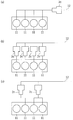
- or (c) is the schematic which shows various embodiment at the time of employ
- FIG. 1 shows an outline of the overall configuration of a gas engine 1 according to the present invention
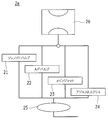
- FIG. 2 shows a mixing portion 2a of fuel and intake air in the gas engine 1
- FIG. 3 shows a solenoid valve 21 in the gas engine 1
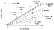
- FIG. 4 shows a correlation diagram between the intake air flow rate by the A / F valve 22 and the fuel gas flow rate
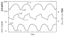
- FIG. 4 shows a control diagram of the perturbation control by the control unit 10 of the gas engine 1
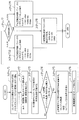
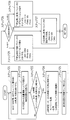
- FIG. 5 shows a flowchart of control by the control unit 10 when considering the above.
- This gas engine 1 includes a solenoid valve 21 and an A / F valve 22, and is based on a reference opening B of the A / F valve 22 when a stoichiometric operation is performed at a predetermined engine speed and load with a reference fuel gas.
- the opening of the A / F valve 22 is set to a smaller value, and perturbation is performed by the solenoid valve 21, and the stoichiometric operation is performed at a predetermined engine speed and load with the reference fuel gas.
- the control unit 10 performs perturbation by the solenoid valve 21 by resetting the opening of the A / F valve 22 to be larger. It has.
- a mixing unit 2 a that mixes air and fuel gas is provided in an intake passage 12 connected to the cylinder head 11.
- a throttle valve 2 b is provided between the mixing unit 2 a and the cylinder head 11. Is provided.
- the mixing unit 2a and the throttle valve 2b constitute an intake unit 2, and the intake unit 2 is controlled by a signal from the control unit 10.
- a solenoid valve 21, an A / F valve 22, a main jet 23, and an adjusting screw 24 are connected in parallel between a regulator 25 and a mixer 26.
- the solenoid valve 21 is configured such that a movable valve biased to close the flow path by a biasing force such as a leaf spring or a spring is moved by an electromagnetic coil and opened to a predetermined opening degree.
- the solenoid valve 21 is opened and closed at a speed of 25 hertz, and the opening degree can be adjusted by changing the duty ratio at the time of opening and closing.
- the solenoid valve 21 is not limited to the one having a frequency of 25 Hz, and may be a solenoid valve 21 having various frequencies used in this kind of perturbation control. With this configuration, the solenoid valve 21 has a small flow rate adjustment range, but allows quick flow rate adjustment. Further, the flow characteristic valve constituting the solenoid valve 21 may be constituted by a proportional control valve.
- the A / F valve 22 is configured so that the opening degree of the movable valve can be adjusted for each step by the rotation of the stepping motor. With this configuration, the A / F valve 22 cannot perform quick flow rate adjustment, but has a large flow rate adjustment range so that it can accommodate a wide range of excess air ratio.
- the main jet 23 is a valve configured to adjust the amount of fuel flowing from the regulator 25 to the mixer 26 together with the solenoid valve 21 and the A / F valve 22, and is different from the solenoid valve 21 and the A / F valve 22 described above.
- the opening is fixed by the number of the main jet 23 to be used.
- the adjustment screw 24 is a valve configured to manually adjust the amount of fuel gas, and is usually fixed together with the main jet 23.
- the regulator 25 controls the pressure of the fuel gas so that the fuel gas can be always supplied at a constant pressure.
- the mixer 26 is composed of a venturi tube that mixes air and fuel gas.
- the mixer 26 is configured to mix fuel gas and air by the venturi effect of the air sucked according to the opening degree of the throttle valve 2b provided on the downstream side.
- the exhaust passage 13 connected to the cylinder head 11 is provided with a silencer 3a, and a three-way catalyst 3b is provided between the silencer 3a and the cylinder head 11.
- An all-region sensor 31 is provided on the exhaust gas inlet side of the three-way catalyst 3b, and an oxygen sensor 32 is provided on the outlet side.
- the lean operation of 6) can be controlled.
- the mixing unit 2a opens the solenoid valve 21 in the middle of the opening / closing region with the A / F valve 22 opened at an intermediate opening of the opening / closing region, for example, 50%.
- the reference opening B is set to 50% of the time average opening.
- the control unit 10 controls the degree of opening and closing of the solenoid valve 21 so that the air-fuel ratio fluctuates on the lean side and the rich side around the reference opening B of the stoichiometric operation, whereby the excess air ratio of the stoichiometric air-fuel ratio is increased.
- the reason why the intermediate opening of the opening / closing region is set is that the intermediate opening has higher accuracy of proportional control than the small opening or large opening region. Therefore, it is not necessary to stick to such an intermediate opening when the accuracy of proportional control is the same over the entire opening / closing area by performing correction control in a small opening area or a large opening area.
- the A / F valve 22 may be set to an opening larger than the intermediate opening during the stoichiometric operation in consideration of closing during the lean operation. preferable.
- the reference opening B is assumed that the solenoid valve 21 has a time average opening of 50% and the A / F valve 22 has an opening of 50%.
- the A / F valve 22 is set to an opening of 50%
- the solenoid valve 21 is set to an average opening of 50%
- a reference fuel gas of a predetermined calorie is set.
- the engine speed and load when the reference opening B is set Even if the stoichiometric operation is carried out, the calorie of the fuel gas is insufficient, and therefore the stoichiometric operation cannot be performed at a predetermined engine speed or load unless the fuel gas is supplemented by this shortage. Therefore, when using fuel gas that lacks calories in actual operation, the actual valve opening A is used to perform stoichiometric operation at the engine speed and load when the reference opening B is set. It is reset to the increased corrected reference opening Ai in which the valve opening A is increased from the reference opening B by the calorie shortage. The change to the increased correction reference opening Ai is performed by resetting the valve opening A of the A / F valve 22 to a large value.
- the calorie of the fuel gas actually supplied is higher than the reference fuel gas, even if the stoichiometric operation is performed at the engine speed or load when the reference opening B is set, the surplus calorie of the fuel gas Therefore, unless the fuel gas is reduced by this surplus, the stoichiometric operation cannot be performed at a predetermined engine speed or load. Therefore, when fuel gas with a high calorie value is used in actual driving, the actual valve opening A is calculated in order to perform stoichiometric operation at the engine speed and load when the reference opening B is set.
- the reduced correction reference opening degree Ad is set by reducing the valve opening degree A from the reference opening degree B by the surplus.
- the change to the reduced correction reference opening degree Ad is performed by resetting the valve opening degree A of the A / F valve 22 to be smaller.
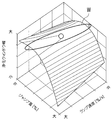
- the increase correction reference opening Ai and the decrease correction reference opening Ad in FIG. 3 are examples, and the stoichiometric operation is performed at a predetermined engine speed and load using the actually supplied fuel gas. In this case, it is determined each time how far the actual valve opening A of the A / F valve 22 is from the reference opening B, and the valve opening A of the A / F valve 22 is reset. .
- the reference opening degree B it is determined whether or not the reference opening degree B is reached when the engine speed and load in the stoichiometric operation are fixed. If the actual opening degree A is deviated, the A / F valve 22 is determined. The valve opening A is increased or decreased to be reset to the increased correction reference opening Ai or the decreased correction reference opening Ad. That is, the actual valve opening A is reset based on the engine speed and load in the stoichiometric operation, but the actual valve opening A of the A / F valve 22 is reset based on the reference opening B. May be. That is, when the reference opening degree B is set, it is determined whether or not a predetermined engine speed or load is obtained by the stoichiometric operation.
- the stoichiometric operation that should be originally obtained at the reference opening degree B is determined.
- the actual valve opening A of the A / F valve 22 is increased or decreased to be set to the increased correction reference opening Ai or the decreased correction reference opening Ad so that the engine speed and load at Also good.
- the perturbation control is performed by controlling the opening / closing degree of the solenoid valve 21.
- the solenoid valve 21 is changed from fully closed to fully opened at the increased correction reference opening Ai, the change amount Vi of the excess air ratio is changed, and at the decrease correction reference opening Ad, the solenoid valve 21 is changed from fully closed to full opening. This is greatly different from the change amount Vd of the excess air ratio.
- This is performed by adjusting the opening degree of the A / F valve 22 while keeping the time average opening degree at 50%. At this time, if the reference fuel gas is supplied, the opening degree of the A / F valve 22 is also maintained at 50% and becomes the reference opening degree B.
- control of the perturbation by the control unit 10 is performed by measuring the entire region sensor 31 provided on the inlet side of the three-way catalyst 3b and the oxygen sensor 32 provided on the outlet side of the three-way catalyst 3b, which is a subsequent stage. This is performed by controlling the degree of opening and closing of the solenoid valve 21 based on the detection result.
- This perturbation control is performed by the control unit 10 as follows.
- the oxygen concentration of the exhaust gas immediately before flowing into the three-way catalyst 3b is measured by the entire region sensor 31.
- the solenoid valve 21 is closed to the lean side more excessively than the stoichiometric operation is set, as shown in FIG.
- the entire region sensor 31 on the upstream side of the three-way catalyst 3b is determined to be lean when the solenoid valve 21 is closed to the lean side with respect to the stoichiometry. Therefore, in accordance with this determination, the solenoid valve 21 is Open to the rich side more excessively than the stoichiometric setting.
- the oxygen stored in the three-way catalyst 3b is released into the exhaust gas to purify the exhaust gas, but the oxygen stored in the three-way catalyst 3b is depleted, so that the rear side of the three-way catalyst 3b
- the oxygen sensor 32 provided at the position shifts to the rich side after a predetermined response time from the switching of the solenoid valve 21.
- the oxygen sensor 32 on the rear stage side of the three-way catalyst 3b causes the air-fuel ratio to be different between the lean side and the rich side of the stoichiometric operation. Changes gently. At this time, the three-way catalyst 3b repeats the occlusion and release of oxygen, so that the activated state of the catalyst is maintained.
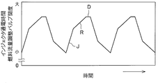
- the control parameter for the valve opening by the solenoid valve 21 includes a jump-up amount J for suddenly opening the valve in a predetermined time, and then a ramp-up speed R for gently opening the valve in the predetermined time. Next, it is determined by the delay time D until the solenoid valve 21 is suddenly closed.
- a control map that takes these into consideration is input to the control unit 10, and ideal perturbation control is performed by controlling each of the air-fuel ratio control parameters described above so that an optimal purification window W is obtained. It is made to be able to.
- This stoichiometric operation is performed by adjusting the opening degree of the A / F valve 22 while keeping the time average value of the opening degree of the solenoid valve 21 at 50% (step 1).
- the fuel gas should be supplied at the reference opening B if the stoichiometric operation is performed at the engine speed and load when the reference opening B is set.
- the fuel gas supplied to the gas engine 1 during actual operation is not the same as the gas component when the reference opening degree B is determined, and the calorie of the fuel gas increases or decreases during the day. fluctuate.
- step 2 the engine speed and load during the stoichiometric operation are detected over a certain period (step 2). If the reference fuel gas is supplied, it should be the reference opening B, but if the calorie of the fuel gas is lower than the reference fuel gas, the actual valve opening A of the A / F valve 22 is the reference opening B. The increased correction reference opening Ai is larger than the opening B. When the calorie of the fuel gas is higher than the reference fuel gas, the actual valve opening A of the A / F valve 22 becomes a reduced correction reference opening Ad that is smaller than the reference opening B.
- step 3 the time history of the valve opening A of the A / F valve 22 in a certain period in which the engine speed and load during the stoichiometric operation are detected is detected (step 3).
- step 4 the time during which the engine speed and load during the stoichiometric operation are constant is detected (step 4).
- the predetermined time does not reach the predetermined time, the actual valve opening A is not stable, and the control from step 2 is repeated until the stable valve opening A is measured. .
- the predetermined time reaches the predetermined time, it is detected as the actual valve opening A (step 5).
- control map of the reference opening B is read (step 6), and the actual valve opening A and the reference opening B are compared (step 7).
- the perturbation control by the solenoid valve 21 is performed with the air-fuel ratio control parameter according to the control map of the reference opening B (step 8). Repeat the control.
- the solenoid valve 21 is set with the air-fuel ratio control parameter corrected in the control map of the reduced correction reference opening Ad. (Step 9), and thereafter the control from step 1 is repeated. At this time, the air-fuel ratio control parameter is set by resetting any one or more of the jump amount J, the ramp speed R, and the delay time D to a smaller value.
- the solenoid valve is set with the air-fuel ratio control parameter corrected in the control map of the increased correction reference opening Ai.
- the perturbation control by 21 is performed (step 10), and thereafter the control from step 1 is repeated.
- the air-fuel ratio control parameter is set by setting any one or more of the jump amount J, the ramp speed R, and the delay time D to a large value.
- the actual valve opening A is corrected to the reduced correction reference opening Ad whose opening is smaller than the reference opening B or the increased correction reference opening Ai whose opening is larger than the reference opening B.
- the air-fuel ratio is changed at a predetermined pitch of about 1 to 2 seconds, so if the fuel gas calories change during the perturbation control, The change overlaps with the change in the air-fuel ratio due to perturbation control, making it difficult to distinguish. Therefore, during the perturbation control, the fluctuation range of the air-fuel ratio obtained from the whole region sensor 31 is compared with the fluctuation range when the perturbation control is performed at the reference opening B, and the calorie change of the fuel gas is calculated from the difference.
- the air / fuel ratio fluctuation obtained from the whole area sensor 31 is an appropriate value, that is, the fluctuation width obtained when perturbation control is performed at the reference opening B using the reference fuel gas. Set the parameter again.
- the gas engine 1 configured as described above, it is possible to know the calorie change of the fuel gas by grasping how much the actual valve opening A is deviated from the reference opening B.
- the A / F valve 22 is reset from the reference opening B to the increased correction reference opening Ai or the decreased correction reference opening Ad, and then the stoichiometric operation, lean operation, and perturbation of the gas engine 1 is performed. Since the control is performed, as shown in FIG. 6, the air-fuel ratio control parameters such as the jump amount J and the ramp speed R can be appropriately determined, and the purification window W during the control can be kept wide. Therefore, the period during which the exhaust gas purification performance can be maintained becomes longer, and the maintenance interval can be extended. Further, it is not necessary to increase the amount and capacity of the noble metal of the catalyst, and the cost of the catalyst can be prevented from increasing. Further, the gas engine 1 can be operated even when fuel gas having a large calorie change is used. Further, the fuel gas can be used in a plurality of countries and regions having different calories.
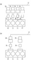
- one mixing section 2a is provided in the intake passage 12, but one mixing section 2a is provided in each cylinder head 11 of the gas engine 1 as shown in FIG. As shown in FIG. 8B, it may be provided in units of two or more cylinder heads 11 (two in the drawing).
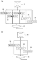
- the mixing unit 2a is configured to control the solenoid valve 21 and the A / F valve 22 having different flow characteristics, but as shown in FIG.
- it may be configured such that the same fuel flow rate adjusting valve 20 can be controlled by providing two or three or more (three in the drawing).
- the fuel flow rate adjustment valve 20 that operates in the same manner as the solenoid valve 21 in the present embodiment and the fuel flow rate adjustment valve 20 that operates in the same manner as the A / F valve 22 are provided.
- each fuel flow rate adjustment valve 20 is configured to operate in the same manner as the solenoid valve 21 in the present embodiment and to operate in the same manner as the A / F valve 22. May be.
- various types of valves used for this type of fuel gas control such as butterfly valves and solenoid valves, can be used as the fuel flow rate adjusting valve 20.
- the mixing unit 2a describes the gas engine 1 having two adjustment valves, the solenoid valve 21 and the A / F valve 22, but as shown in FIG.
- One fuel flow rate adjusting valve 20 may be provided.
- This stoichiometric operation is performed by adjusting the opening of the fuel flow rate adjusting valve 20.
- the fuel gas should be supplied at the reference opening B if the stoichiometric operation is performed at the engine speed and load when the reference opening B is set.
- the fuel gas supplied to the gas engine 1 during actual operation is not the same as the gas component when the reference opening degree B is determined, and the calorie of the fuel gas increases or decreases during the day. fluctuate.
- the engine speed and load during the stoichiometric operation are detected over a certain period (step 21). If the reference fuel gas is supplied, it should be the reference opening B. However, if the calorie of the fuel gas is lower than the reference fuel gas, the actual valve opening A of the fuel flow control valve 20 is the reference opening B. The increased correction reference opening Ai is larger than the opening B. When the calorie of the fuel gas is higher than that of the reference fuel gas, the actual valve opening A of the fuel flow rate adjustment valve 20 becomes a reduced correction reference opening Ad that is smaller than the reference opening B.
- a time history of the valve opening A of the fuel flow rate adjustment valve 20 is detected during a certain period in which the engine speed and load during the stoichiometric operation are detected (step 22).
- step 23 the time during which the engine speed and load during the stoichiometric operation are constant is detected.
- the predetermined time does not reach the predetermined time, it means that the actual valve opening A is not stable, and the control from step 21 is repeated until the stable valve opening A is measured. .
- the predetermined time reaches the predetermined time, the actual valve opening A is detected (step 24).
- control map of the reference opening B is read (step 25), and the actual valve opening A and the reference opening B are compared (step 26).
- perturbation control is performed by the fuel flow rate adjusting valve 20 with the air-fuel ratio control parameter according to the control map of the reference opening B (step 27).
- the control from 21 is repeated.
- the fuel flow rate adjusting valve 20 uses the air-fuel ratio control parameter corrected in the control map of the reduced correction reference opening Ad. Perturbation control is performed (step 28), and thereafter the control from step 21 is repeated. At this time, the air-fuel ratio control parameter is set by resetting any one or more of the jump amount J, the ramp speed R, and the delay time D to a smaller value.
- the fuel flow rate adjustment is performed with the air-fuel ratio control parameter corrected in the control map of the increased corrected reference opening Ai.
- Perturbation control is performed by the valve 20 (step 29), and thereafter, the control from step 21 is repeated.
- the air-fuel ratio control parameter is set by setting any one or more of the jump amount J, the ramp speed R, and the delay time D to a large value.
- the air-fuel ratio fluctuation width obtained from the entire range sensor 31 is compared with the fluctuation width when the perturbation control is performed at the reference opening degree B, and the fuel gas is calculated from the difference. Estimate the calorie change.
- the air / fuel ratio fluctuation obtained from the whole area sensor 31 is an appropriate value, that is, the fluctuation width obtained when perturbation control is performed at the reference opening B using the reference fuel gas. Set the parameter again.
- the same effects as those of the gas engine 1 having the two adjusting valves described above can be obtained.
- the intake portion 2 is configured by the mixing portion 2a having one or a plurality of valves such as the fuel flow rate adjusting valve 20, the solenoid valve 21 and the A / F valve 22, and the throttle valve 2b.
- this intake portion may be constituted by a single injector 2c, or provided in each cylinder head 11 as shown in FIG. 11 (b). Further, it may be configured by an injector 2c, or may be configured by an injector 2c provided for each of a plurality of cylinder heads 11 (two in the drawing) as shown in FIG. .
- what corresponds to the reference opening degree B in the above embodiment is the reference valve opening time Bt of the injector 2c.
- the injector 2c when the stoichiometric operation of the gas engine 1 is performed at a predetermined engine speed and load while supplying a predetermined calorie fuel gas as a reference with an excess air ratio ( ⁇ 1) of the theoretical air-fuel ratio.
- the reference valve opening time ( energization time) Bt.
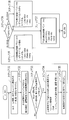
- FIG. 12 shows a case where control is performed in consideration of changes in the calorie of the fuel gas in the gas engine 1 having an intake section composed of one injector 2c.
- the fuel gas should be supplied at the reference valve opening time Bt.
- the fuel gas supplied to the gas engine 1 during actual operation is not the same as the gas component when the reference valve opening time Bt is determined, and the calorie of the fuel gas increases or decreases during the day. It fluctuates.
- the engine speed and load during the stoichiometric operation are detected over a certain period (step 31). If the reference fuel gas is supplied, the reference valve opening time Bt should be reached. However, if the calorie of the fuel gas is lower than the reference fuel gas, the actual valve opening time At of the injector 2c is the reference valve opening time Bt. The increased correction reference valve opening time Ati is larger than the time Bt. When the calorie of the fuel gas is higher than the reference fuel gas, the actual valve opening time At of the injector 2c becomes the reduced correction reference valve opening time Atd whose opening is smaller than the reference valve opening time Bt.
- a time history of the valve opening time At of the injector 2c during a certain period in which the engine speed and load during the stoichiometric operation are detected is detected (step 32).
- step 33 the time during which the engine speed and load during the stoichiometric operation are constant is detected (step 33).
- the predetermined time does not reach the predetermined time, it means that the actual valve opening time At is not stable, and the control from step 31 is repeated until the stable valve opening time At is measured. .
- the predetermined time reaches the predetermined time, it is detected as the actual valve opening time At (step 34).
- control map of the reference valve opening time Bt is read (step 35), and the actual valve opening time At and the reference valve opening time Bt are compared (step 36).
- the perturbation control by the injector 2c is performed with the air-fuel ratio control parameter according to the control map of the reference valve opening time Bt (step 37). Repeat the control from.
- Step 38 the perturbation control by the injector 2c with the air-fuel ratio control parameter corrected in the control map of the reduced correction reference valve opening time Atd. (Step 38), and thereafter, the control from step 31 is repeated.
- the air-fuel ratio control parameter is set by resetting any one or more of the jump amount J, the ramp speed R, and the delay time D to a smaller value.
- the injector 2c uses the air-fuel ratio control parameter corrected in the control map of the increased correction reference valve opening time Ati. Perturbation control is performed (step 39), and thereafter the control from step 31 is repeated. At this time, the air-fuel ratio control parameter is set by setting any one or more of the jump amount J, the ramp speed R, and the delay time D to a large value.
- the air-fuel ratio fluctuation width obtained from the entire range sensor 31 is compared with the fluctuation width when the perturbation control is performed at the reference opening degree B, and the fuel gas is calculated from the difference. Estimate the calorie change.
- the air / fuel ratio fluctuation obtained from the whole area sensor 31 is an appropriate value, that is, the fluctuation width obtained when perturbation control is performed at the reference opening B using the reference fuel gas. Set the parameter again.
- the gas engine 1 configured as described above, it is possible to know the calorie change of the fuel gas by grasping how much the actual valve opening time At is deviated from the reference valve opening time Bt.
- the stoichiometric operation, lean operation, and perturbation of the gas engine 1 are performed after the injector 2c is reset from the reference valve opening time Bt to the increased correction reference valve opening time Ati or the decreased correction reference valve opening time Atd. Since the control is performed, as shown in FIG. 6, the air-fuel ratio control parameters such as the jump amount J and the ramp speed R can be appropriately determined, and the purification window W during the control can be kept wide. Therefore, the period during which the exhaust gas purification performance can be maintained becomes longer, and the maintenance interval can be extended. Further, it is not necessary to increase the amount and capacity of the noble metal of the catalyst, and the cost of the catalyst can be prevented from increasing. Further, the gas engine 1 can be operated even when fuel gas having a large calorie change is used. Further, the fuel gas can be used in a plurality of countries and regions having different calories.
- the injector 2c is proportional to the adjustment amount of the valve opening time reset from the reference valve opening time Bt to the increased correction reference valve opening time Ati or the decreased correction reference valve opening time Atd.
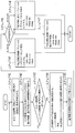
- FIG. 13 shows a case where control is performed in consideration of a change in the calorie of the fuel gas in the gas engine 1 having an intake section in which each cylinder head 11 is provided with one injector 2c.
- the fuel gas should be supplied at the reference valve opening time Bt.
- the fuel gas supplied to the gas engine 1 during actual operation is not the same as the gas component when the reference valve opening time Bt is determined, and the calorie of the fuel gas increases or decreases during the day. It fluctuates.
- the engine speed and load during the stoichiometric operation are detected over a certain period (step 41). If the reference fuel gas is supplied, the reference valve opening time Bt should be reached. However, if the calorie of the fuel gas is lower than the reference fuel gas, the actual valve opening time At of the injector 2c is the reference valve opening time Bt. The increased correction reference valve opening time Ati is larger than the time Bt. When the calorie of the fuel gas is higher than the reference fuel gas, the actual valve opening time At of the injector 2c becomes the reduced correction reference valve opening time Atd whose opening is smaller than the reference valve opening time Bt.
- a time history of the valve opening time At of the injector 2c during a certain period in which the engine speed and load during the stoichiometric operation are detected is detected (step 42).
- step 43 the time during which the engine speed and load during the stoichiometric operation are constant is detected (step 43).
- the predetermined time does not reach the predetermined time, it means that the actual valve opening time At is not stable, and the control from step 41 is repeated until the stable valve opening time At is measured. .
- the predetermined time reaches the predetermined time, it is detected as the actual valve opening time At (step 44).
- control map of the reference valve opening time Bt is read (step 45), and the actual valve opening time At and the reference valve opening time Bt are compared (step 46).
- perturbation control by the injector 2c is performed with the air-fuel ratio control parameter according to the control map of the reference valve opening time Bt (step 47). Repeat the control from.
- Step 48 the perturbation control by the injector 2c with the air-fuel ratio control parameter corrected in the control map of the reduced correction reference valve opening time Atd. (Step 48), and thereafter, the control from step 41 is repeated.
- the air-fuel ratio control parameter is set by resetting any one or more of the jump amount J, the ramp speed R, and the delay time D to a smaller value.
- the injector 2c uses the air-fuel ratio control parameter corrected in the control map of the increased correction reference valve opening time Ati. Perturbation control is performed (step 49), and thereafter the control from step 41 is repeated. At this time, the air-fuel ratio control parameter is set by setting any one or more of the jump amount J, the ramp speed R, and the delay time D to a large value.
- the air-fuel ratio fluctuation width obtained from the entire range sensor 31 is compared with the fluctuation width when the perturbation control is performed at the reference opening degree B, and the fuel gas is calculated from the difference. Estimate the calorie change.
- the air / fuel ratio fluctuation obtained from the whole area sensor 31 is an appropriate value, that is, the fluctuation width obtained when perturbation control is performed at the reference opening B using the reference fuel gas. Set the parameter again.
- the gas engine 1 has a configuration in which the entire region sensor 31 is provided on the inlet side of the three-way catalyst 3b.
- the entire region sensor 31 may be replaced with an oxygen sensor.
- the sensor may be provided with both the whole area sensor 31 and the oxygen sensor.
- the output amplitude of the oxygen sensor cannot accurately represent the actual air-fuel ratio amplitude. Correction according to the ratio of the difference reset to the corrected reference opening degree Ad or the ratio of the difference reset from the reference valve opening time Bt to the increased correction reference valve opening time Ati or the reduced correction reference valve opening time Atd It is necessary to make corrections according to the ratio of the difference reset to the corrected reference opening degree Ad or the ratio of the difference reset from the reference valve opening time Bt to the increased correction reference valve opening time Ati or the reduced correction reference valve opening time Atd It is necessary to make corrections according to the ratio of the difference reset to the corrected reference opening degree Ad or the ratio of the difference reset from the reference valve opening time Bt to the increased correction reference valve opening time Ati or the reduced correction reference valve opening time Atd
- the gas engine 1 is configured to be able to switch between stoichiometric operation and lean operation, but may be a gas engine 1 configured to perform only stoichiometric operation.
- the same effect as the gas engine 1 having the one injector 2c described above can be obtained.
- Each gas engine 1 configured as described above can be suitably used as a drive source of a gas heat pump device (not shown). Moreover, this gas engine 1 can be used suitably also as a drive source of a cogeneration apparatus (illustration omitted).
- the gas engine 1 is described.
- the present invention may be applied to various encines in which perturbation control is performed.
Landscapes
- Engineering & Computer Science (AREA)
- Chemical & Material Sciences (AREA)
- Combustion & Propulsion (AREA)
- Mechanical Engineering (AREA)
- General Engineering & Computer Science (AREA)
- Analytical Chemistry (AREA)
- Chemical Kinetics & Catalysis (AREA)
- General Chemical & Material Sciences (AREA)
- Oil, Petroleum & Natural Gas (AREA)
- Electrical Control Of Air Or Fuel Supplied To Internal-Combustion Engine (AREA)
- Output Control And Ontrol Of Special Type Engine (AREA)
- Combined Controls Of Internal Combustion Engines (AREA)
Abstract
Description
10 制御部
2 吸気部
2c インジェクタ
20 燃料流量調整バルブ
21 ソレノイドバルブ
22 A/Fバルブ
31 全領域センサ
32 酸素センサ
A 実際の開度
At 実際の開弁時間
Ai 増修正基準開度
Ati 増修正基準開弁時間
Ad 減修正基準開度
Atd 減修正基準開弁時間
B 基準開度
Bt 基準開弁時間
J ジャンプ量(空燃比制御パラメータ)
R ランプ速度(空燃比制御パラメータ)
D ディレイタイム(空燃比制御パラメータ)
Claims (10)
- 一つの燃料流量調整バルブで空燃比を制御するようになされたガスエンジンにおいて、
基準燃料ガスによる特定のエンジン運転状況において、燃料流量調整バルブが基準開度に設定されており、
実際の運転時に、特定のエンジン運転状況におけるバルブ開度が、設定した基準開度よりも小さい場合、または、基準開度におけるエンジン出力が、特定のエンジン運転状況から得られる設定出力より高出力の場合、燃料流量調整バルブの開度を基準開度よりも小さくした減修正基準開度に設定し直し、
特定のエンジン運転状況におけるバルブ開度が、設定した基準開度よりも大きい場合、または、基準開度におけるエンジンの出力が、特定のエンジン運転状況から得られる設定出力より低出力の場合、燃料流量調整バルブの開度を基準開度よりも大きく設定し直す制御部を備えたことを特徴とするガスエンジン。 - 燃料流量調整バルブが複数個となされ、これら複数個の燃料流量調整バルブによって前記一つの燃料流量調整バルブの必要流量が確保されてなる請求項1に記載のガスエンジン。
- 制御部は、減修正基準開度に設定し直した場合は、燃料流量調整バルブによる空燃比制御パラメータの値を、減修正の比率に応じて小さく設定し直し、
増修正基準開度に設定し直した場合は、燃料流量調整バルブによる空燃比制御パラメータの値を、増修正の比率に応じて大きく設定し直すようになされた請求項1に記載のガスエンジン。 - 制御部は、減修正基準開度に設定し直した場合は、燃料流量調整バルブによる空燃比制御パラメータの値を、減修正の比率に応じて小さく設定し直し、
増修正基準開度に設定し直した場合は、燃料流量調整バルブによる空燃比制御パラメータの値を、増修正の比率に応じて大きく設定し直すようになされた請求項2に記載のガスエンジン。 - 複数の燃料流量調整バルブは、第二バルブよりも応答性が低く燃料流量調整幅が大きい第一バルブと、第一バルブよりも応答性が高く燃料流量調整幅が小さい第二バルブとを具備し、第二バルブでパータベーションを行うように構成され、
基準燃料ガスによる特定のエンジン運転状況において、第二バルブの開度が所定値となるように第一バルブの開度が調整されて基準開度が設定されており、
実際の運転時に、特定のエンジン運転状況におけるバルブ開度が、設定した基準開度よりも小さい場合、または、基準開度におけるエンジンの出力が、特定のエンジン運転状況から得られる設定出力より高出力の場合、第一バルブの開度を基準開度よりも小さく設定し直し、
特定のエンジン運転状況におけるバルブ開度が、設定した基準開度よりも大きい場合、または、基準開度におけるエンジンの出力が、特定のエンジン運転状況から得られる設定出力より低出力の場合、第一バルブの開度を基準開度よりも大きく設定し直す制御部を備えた請求項2に記載のガスエンジン。 - 制御部は、減修正基準開度に設定し直した場合は、第二バルブによる空燃比制御パラメータの値を、減修正の比率に応じて小さく設定し直し、
増修正基準開度に設定し直した場合は、第二バルブによる空燃比制御パラメータの値を、増修正の比率に応じて大きく設定し直すようになされた請求項5記載のガスエンジン。 - 一つのインジェクタで空燃比を制御するようになされたシングルポイントインジェクジョンのガスエンジンにおいて、
基準燃料ガスによる特定のエンジン運転状況において、インジェクタの開弁時間が基準開弁時間に設定されており、
実際の運転時に、特定のエンジン運転状況における開弁時間が、設定した基準開弁時間よりも小さい場合、または、基準開弁時間におけるエンジン出力が、特定のエンジン運転状況から得られる設定出力より高出力の場合、インジェクタの開弁時間を基準開弁時間よりも少なくした減修正基準開弁時間に設定し直し、
特定のエンジン運転状況における開弁時間が、設定した基準開弁時間よりも大きい場合、または、基準開弁時間におけるエンジン出力が、特定のエンジン運転状況から得られる設定出力より低出力の場合、インジェクタの開弁時間を基準開弁時間よりも多くした増修正基準開弁時間に設定し直す制御部を備えたことを特徴とするガスエンジン。 - 制御部は、減修正基準開弁時間に設定し直した場合は、インジェクタによる空燃比制御パラメータの値を、減修正の比率に応じて少なく設定し直し、
増修正基準開弁時間に設定し直した場合は、インジェクタによる空燃比制御パラメータの値を、増修正の比率に応じて多く設定し直すようになされた請求項7に記載のガスエンジン。 - 各シリンダヘッド毎または複数のシリンダヘッド毎にインジェクタが設けられたマルチポイントインジェクションとなされた請求項7または8に記載のガスエンジン。
- 排気路の触媒上流側に全領域空燃比センサが設けられ、
制御部は、全領域空燃比センサによって測定した空燃比に基づいてパータベーション制御を行うとともに、この際測定される空燃比の振れ幅からガスカロリーを推定して空燃比制御パラメータの値を調整する請求項1ないし9の何れか一に記載のガスエンジン。
Priority Applications (3)
| Application Number | Priority Date | Filing Date | Title |
|---|---|---|---|
| US14/648,159 US20150300282A1 (en) | 2012-11-30 | 2013-10-25 | Gas engine |
| CA2893107A CA2893107A1 (en) | 2012-11-30 | 2013-10-25 | Gas engine |
| EP13858126.9A EP2910754B1 (en) | 2012-11-30 | 2013-10-25 | Gas engine |
Applications Claiming Priority (2)
| Application Number | Priority Date | Filing Date | Title |
|---|---|---|---|
| JP2012-262261 | 2012-11-30 | ||
| JP2012262261A JP6014474B2 (ja) | 2012-11-30 | 2012-11-30 | ガスエンジン |
Publications (1)
| Publication Number | Publication Date |
|---|---|
| WO2014083985A1 true WO2014083985A1 (ja) | 2014-06-05 |
Family
ID=50827631
Family Applications (1)
| Application Number | Title | Priority Date | Filing Date |
|---|---|---|---|
| PCT/JP2013/078992 Ceased WO2014083985A1 (ja) | 2012-11-30 | 2013-10-25 | ガスエンジン |
Country Status (5)
| Country | Link |
|---|---|
| US (1) | US20150300282A1 (ja) |
| EP (1) | EP2910754B1 (ja) |
| JP (1) | JP6014474B2 (ja) |
| CA (1) | CA2893107A1 (ja) |
| WO (1) | WO2014083985A1 (ja) |
Cited By (3)
| Publication number | Priority date | Publication date | Assignee | Title |
|---|---|---|---|---|
| WO2016030002A1 (de) * | 2014-08-25 | 2016-03-03 | Mtu Friedrichshafen Gmbh | Verfahren zum betreiben einer brennkraftmaschine und brennkraftmaschine |
| EP3054132A1 (en) * | 2015-02-06 | 2016-08-10 | Caterpillar Motoren GmbH & Co. KG | Method for controlling an internal combustion engine |
| CN115217650A (zh) * | 2022-07-28 | 2022-10-21 | 潍柴动力股份有限公司 | 发动机空燃比的控制方法、装置及控制器 |
Families Citing this family (6)
| Publication number | Priority date | Publication date | Assignee | Title |
|---|---|---|---|---|
| JP6134587B2 (ja) * | 2013-06-11 | 2017-05-24 | ヤンマー株式会社 | ガスエンジン |
| JP6318010B2 (ja) * | 2014-06-03 | 2018-04-25 | ヤンマー株式会社 | バイオマスガス専焼エンジン |
| CN110905694B (zh) * | 2019-12-23 | 2024-12-20 | 潍柴西港新能源动力有限公司 | 天然气发动机用燃料双喷射系统喷射控制方法 |
| CN111520244B (zh) * | 2020-04-30 | 2023-05-12 | 四川华气动力有限责任公司 | 一种发动机燃气回路的运行控制方法及其控制系统 |
| CN114251180B (zh) * | 2021-12-22 | 2024-05-28 | 重庆康明斯发动机有限公司 | 燃气发动机启动控制的方法、装置、设备以及存储介质 |
| JP7764359B2 (ja) * | 2022-12-28 | 2025-11-05 | 株式会社クボタ | ガスエンジン |
Citations (3)
| Publication number | Priority date | Publication date | Assignee | Title |
|---|---|---|---|---|
| JP2003148187A (ja) | 2001-11-12 | 2003-05-21 | Tokyo Gas Co Ltd | 内燃機関の制御装置及び制御方法 |
| WO2007144745A1 (en) * | 2006-06-13 | 2007-12-21 | Toyota Jidosha Kabushiki Kaisha | Fuel property determination system, and fuel property determination method for internal combustion engine |
| EP2481906A1 (en) * | 2011-01-27 | 2012-08-01 | Honda Motor Co., Ltd. | Engine control device and cogeneration apparatus employing the engine control device |
Family Cites Families (10)
| Publication number | Priority date | Publication date | Assignee | Title |
|---|---|---|---|---|
| US4173957A (en) * | 1976-06-14 | 1979-11-13 | Nippon Soken, Inc. | Additional air supply system for an internal combustion engine |
| DE4340885B4 (de) * | 1993-12-01 | 2005-08-11 | Deutz Ag | V-förmig ausgebildete Brennkraftmaschine |
| JP3610682B2 (ja) * | 1996-07-24 | 2005-01-19 | トヨタ自動車株式会社 | 内燃機関の蒸発燃料処理装置 |
| US5988150A (en) * | 1996-12-05 | 1999-11-23 | Toyota Jidosha Kabushiki Kaisha | Evaporated fuel treatment device of engine |
| JP3814913B2 (ja) * | 1997-02-07 | 2006-08-30 | トヨタ自動車株式会社 | ガス燃料内燃機関の制御装置 |
| US6253744B1 (en) * | 1999-03-19 | 2001-07-03 | Unisia Jecs Corporation | Method and apparatus for controlling fuel vapor, method and apparatus for diagnosing fuel vapor control apparatus, and method and apparatus for controlling air-fuel ratio |
| JP3847080B2 (ja) * | 2000-11-22 | 2006-11-15 | 愛三工業株式会社 | Lpgエンジンの燃料制御装置 |
| US6752135B2 (en) * | 2002-11-12 | 2004-06-22 | Woodward Governor Company | Apparatus for air/fuel ratio control |
| JP2006070874A (ja) * | 2004-09-06 | 2006-03-16 | Toyota Industries Corp | ガスエンジンにおける空燃比制御方法及び制御装置 |
| DE102011003681A1 (de) * | 2011-02-07 | 2012-08-09 | Man Diesel & Turbo Se | Verfahren und Vorrichtung zur Anpassung des Betriebszustands eines Verbrennungsmotors |
-
2012
- 2012-11-30 JP JP2012262261A patent/JP6014474B2/ja active Active
-
2013
- 2013-10-25 WO PCT/JP2013/078992 patent/WO2014083985A1/ja not_active Ceased
- 2013-10-25 CA CA2893107A patent/CA2893107A1/en not_active Abandoned
- 2013-10-25 US US14/648,159 patent/US20150300282A1/en not_active Abandoned
- 2013-10-25 EP EP13858126.9A patent/EP2910754B1/en not_active Not-in-force
Patent Citations (9)
| Publication number | Priority date | Publication date | Assignee | Title |
|---|---|---|---|---|
| JP2003148187A (ja) | 2001-11-12 | 2003-05-21 | Tokyo Gas Co Ltd | 内燃機関の制御装置及び制御方法 |
| WO2007144745A1 (en) * | 2006-06-13 | 2007-12-21 | Toyota Jidosha Kabushiki Kaisha | Fuel property determination system, and fuel property determination method for internal combustion engine |
| JP2007332820A (ja) * | 2006-06-13 | 2007-12-27 | Toyota Motor Corp | 内燃機関の燃料性状判定装置 |
| EP2029871A1 (en) * | 2006-06-13 | 2009-03-04 | Toyota Jidosha Kabushiki Kaisha | Fuel property determination system, and fuel property determination method for internal combustion engine |
| CN101466932A (zh) * | 2006-06-13 | 2009-06-24 | 丰田自动车株式会社 | 内燃发动机的燃料特性确定系统及燃料特性确定方法 |
| US20090287396A1 (en) * | 2006-06-13 | 2009-11-19 | Koichi Ueda | Fuel property determination system, and fuel property determination method for internal combustion engine |
| EP2481906A1 (en) * | 2011-01-27 | 2012-08-01 | Honda Motor Co., Ltd. | Engine control device and cogeneration apparatus employing the engine control device |
| US20120197514A1 (en) * | 2011-01-27 | 2012-08-02 | Honda Motor Co., Ltd. | Engine control device and cogeneration apparatus employing the engine control device |
| JP2012154276A (ja) * | 2011-01-27 | 2012-08-16 | Honda Motor Co Ltd | 制御装置及び同装置を備えたコージェネレーション装置 |
Cited By (5)
| Publication number | Priority date | Publication date | Assignee | Title |
|---|---|---|---|---|
| WO2016030002A1 (de) * | 2014-08-25 | 2016-03-03 | Mtu Friedrichshafen Gmbh | Verfahren zum betreiben einer brennkraftmaschine und brennkraftmaschine |
| US10180110B2 (en) | 2014-08-25 | 2019-01-15 | Mtu Friedrichshafen Gmbh | Method for operating an internal combustion engine based on a characteristic value determined from a lamda value, and internal combustion engine |
| EP3054132A1 (en) * | 2015-02-06 | 2016-08-10 | Caterpillar Motoren GmbH & Co. KG | Method for controlling an internal combustion engine |
| CN115217650A (zh) * | 2022-07-28 | 2022-10-21 | 潍柴动力股份有限公司 | 发动机空燃比的控制方法、装置及控制器 |
| CN115217650B (zh) * | 2022-07-28 | 2024-05-17 | 潍柴动力股份有限公司 | 发动机空燃比的控制方法、装置及控制器 |
Also Published As
| Publication number | Publication date |
|---|---|
| EP2910754A4 (en) | 2015-12-23 |
| EP2910754B1 (en) | 2017-10-18 |
| CA2893107A1 (en) | 2014-06-05 |
| JP2014109191A (ja) | 2014-06-12 |
| JP6014474B2 (ja) | 2016-10-25 |
| US20150300282A1 (en) | 2015-10-22 |
| EP2910754A1 (en) | 2015-08-26 |
Similar Documents
| Publication | Publication Date | Title |
|---|---|---|
| JP6014474B2 (ja) | ガスエンジン | |
| JP6128975B2 (ja) | ガスエンジン | |
| JP6134587B2 (ja) | ガスエンジン | |
| JP6482946B2 (ja) | ガスエンジン | |
| EP2899386B1 (en) | Internal combustion engine | |
| US7761218B2 (en) | Air-fuel ratio control method of engine and air-fuel ratio control apparatus for same | |
| WO2018096785A1 (ja) | 模擬ガス発生装置、評価装置及び模擬ガス発生方法 |
Legal Events
| Date | Code | Title | Description |
|---|---|---|---|
| 121 | Ep: the epo has been informed by wipo that ep was designated in this application |
Ref document number: 13858126 Country of ref document: EP Kind code of ref document: A1 |
|
| DPE1 | Request for preliminary examination filed after expiration of 19th month from priority date (pct application filed from 20040101) | ||
| REEP | Request for entry into the european phase |
Ref document number: 2013858126 Country of ref document: EP |
|
| WWE | Wipo information: entry into national phase |
Ref document number: 2013858126 Country of ref document: EP |
|
| WWE | Wipo information: entry into national phase |
Ref document number: 14648159 Country of ref document: US |
|
| ENP | Entry into the national phase |
Ref document number: 2893107 Country of ref document: CA |
|
| NENP | Non-entry into the national phase |
Ref country code: DE |