WO2014084256A1 - 車載画像処理装置 - Google Patents
車載画像処理装置 Download PDFInfo
- Publication number
- WO2014084256A1 WO2014084256A1 PCT/JP2013/081898 JP2013081898W WO2014084256A1 WO 2014084256 A1 WO2014084256 A1 WO 2014084256A1 JP 2013081898 W JP2013081898 W JP 2013081898W WO 2014084256 A1 WO2014084256 A1 WO 2014084256A1
- Authority
- WO
- WIPO (PCT)
- Prior art keywords
- parking frame
- image
- frame recognition
- unit
- image processing
- Prior art date
- Legal status (The legal status is an assumption and is not a legal conclusion. Google has not performed a legal analysis and makes no representation as to the accuracy of the status listed.)
- Ceased
Links
Images








Classifications
-
- G—PHYSICS
- G06—COMPUTING OR CALCULATING; COUNTING
- G06V—IMAGE OR VIDEO RECOGNITION OR UNDERSTANDING
- G06V20/00—Scenes; Scene-specific elements
- G06V20/50—Context or environment of the image
- G06V20/56—Context or environment of the image exterior to a vehicle by using sensors mounted on the vehicle
- G06V20/58—Recognition of moving objects or obstacles, e.g. vehicles or pedestrians; Recognition of traffic objects, e.g. traffic signs, traffic lights or roads
- G06V20/586—Recognition of moving objects or obstacles, e.g. vehicles or pedestrians; Recognition of traffic objects, e.g. traffic signs, traffic lights or roads of parking space
-
- B—PERFORMING OPERATIONS; TRANSPORTING
- B60—VEHICLES IN GENERAL
- B60R—VEHICLES, VEHICLE FITTINGS, OR VEHICLE PARTS, NOT OTHERWISE PROVIDED FOR
- B60R1/00—Optical viewing arrangements; Real-time viewing arrangements for drivers or passengers using optical image capturing systems, e.g. cameras or video systems specially adapted for use in or on vehicles
- B60R1/20—Real-time viewing arrangements for drivers or passengers using optical image capturing systems, e.g. cameras or video systems specially adapted for use in or on vehicles
- B60R1/22—Real-time viewing arrangements for drivers or passengers using optical image capturing systems, e.g. cameras or video systems specially adapted for use in or on vehicles for viewing an area outside the vehicle, e.g. the exterior of the vehicle
- B60R1/23—Real-time viewing arrangements for drivers or passengers using optical image capturing systems, e.g. cameras or video systems specially adapted for use in or on vehicles for viewing an area outside the vehicle, e.g. the exterior of the vehicle with a predetermined field of view
- B60R1/27—Real-time viewing arrangements for drivers or passengers using optical image capturing systems, e.g. cameras or video systems specially adapted for use in or on vehicles for viewing an area outside the vehicle, e.g. the exterior of the vehicle with a predetermined field of view providing all-round vision, e.g. using omnidirectional cameras
-
- B—PERFORMING OPERATIONS; TRANSPORTING
- B60—VEHICLES IN GENERAL
- B60R—VEHICLES, VEHICLE FITTINGS, OR VEHICLE PARTS, NOT OTHERWISE PROVIDED FOR
- B60R1/00—Optical viewing arrangements; Real-time viewing arrangements for drivers or passengers using optical image capturing systems, e.g. cameras or video systems specially adapted for use in or on vehicles
- B60R1/20—Real-time viewing arrangements for drivers or passengers using optical image capturing systems, e.g. cameras or video systems specially adapted for use in or on vehicles
- B60R1/22—Real-time viewing arrangements for drivers or passengers using optical image capturing systems, e.g. cameras or video systems specially adapted for use in or on vehicles for viewing an area outside the vehicle, e.g. the exterior of the vehicle
- B60R1/28—Real-time viewing arrangements for drivers or passengers using optical image capturing systems, e.g. cameras or video systems specially adapted for use in or on vehicles for viewing an area outside the vehicle, e.g. the exterior of the vehicle with an adjustable field of view
-
- G—PHYSICS
- G06—COMPUTING OR CALCULATING; COUNTING
- G06V—IMAGE OR VIDEO RECOGNITION OR UNDERSTANDING
- G06V20/00—Scenes; Scene-specific elements
- G06V20/50—Context or environment of the image
- G06V20/56—Context or environment of the image exterior to a vehicle by using sensors mounted on the vehicle
- G06V20/58—Recognition of moving objects or obstacles, e.g. vehicles or pedestrians; Recognition of traffic objects, e.g. traffic signs, traffic lights or roads
-
- G—PHYSICS
- G06—COMPUTING OR CALCULATING; COUNTING
- G06V—IMAGE OR VIDEO RECOGNITION OR UNDERSTANDING
- G06V40/00—Recognition of biometric, human-related or animal-related patterns in image or video data
- G06V40/10—Human or animal bodies, e.g. vehicle occupants or pedestrians; Body parts, e.g. hands
-
- G—PHYSICS
- G08—SIGNALLING
- G08G—TRAFFIC CONTROL SYSTEMS
- G08G1/00—Traffic control systems for road vehicles
- G08G1/16—Anti-collision systems
- G08G1/166—Anti-collision systems for active traffic, e.g. moving vehicles, pedestrians, bikes
-
- G—PHYSICS
- G08—SIGNALLING
- G08G—TRAFFIC CONTROL SYSTEMS
- G08G1/00—Traffic control systems for road vehicles
- G08G1/16—Anti-collision systems
- G08G1/167—Driving aids for lane monitoring, lane changing, e.g. blind spot detection
-
- G—PHYSICS
- G08—SIGNALLING
- G08G—TRAFFIC CONTROL SYSTEMS
- G08G1/00—Traffic control systems for road vehicles
- G08G1/16—Anti-collision systems
- G08G1/168—Driving aids for parking, e.g. acoustic or visual feedback on parking space
-
- H—ELECTRICITY
- H04—ELECTRIC COMMUNICATION TECHNIQUE
- H04N—PICTORIAL COMMUNICATION, e.g. TELEVISION
- H04N7/00—Television systems
- H04N7/18—Closed-circuit television [CCTV] systems, i.e. systems in which the video signal is not broadcast
Definitions
- the present invention relates to an in-vehicle image processing apparatus that recognizes the outside world of a vehicle using an image captured by an in-vehicle camera.
- Patent Document 1 the entire vehicle periphery is imaged by sharing with four in-vehicle cameras mounted on the front, back, left, and right of the vehicle, and an overhead view image is generated by converting and combining each through image, A technique for recognizing a parking frame from an overhead image is disclosed.
- an apparatus that presents a bird's-eye view image to a user presents both a bird's-eye view image and a through image of the vehicle traveling direction. This is because the bird's-eye view image is suitable for the driver to confirm the surroundings of the vehicle, while the through image is more suitable for grasping a distant place or a three-dimensional object.
- the bird's-eye view image has a narrow field of view (approximately 2 m ahead of the host vehicle) compared to a through image that is an image before conversion, and is not suitable for recognizing far away.
- a narrow field of view approximately 2 m ahead of the host vehicle
- a through image that is an image before conversion
- a through image has a wider field of view than a bird's-eye view and can be recognized far away, and therefore, lane recognition and the like are generally processed using a through image.
- the bird's-eye view image is easier to handle in terms of image processing than the through image before conversion, and for example, in the case of deviation prediction from a white line, the calculation from the bird's-eye view image is easier.
- some applications improve the recognition accuracy by using a bird's-eye view image.
- the present invention has been made in view of the above points, and an object of the present invention is to provide an in-vehicle image processing apparatus capable of recognizing the outside world with higher accuracy from an image captured by an in-vehicle camera. is there.
- An in-vehicle image processing apparatus that solves the above-described problems is an image acquisition unit that acquires through images captured by cameras arranged at the front, rear, and side of a vehicle, and converts each acquired through image.
- a parking frame recognition unit that performs a parking frame recognition process for recognizing a parking frame using at least one of the through image and the overhead image.
- the second parking frame recognition process for recognizing the parking frame is performed.
- the parking frame in the predetermined range is recognized using the overhead image
- the parking frame in the area farther than the predetermined range of the overhead image is recognized using the through image.
- Image processing can be performed using an appropriate image according to the situation, and the parking frame can be recognized with higher accuracy.
- the flowchart explaining the display switching method The image figure which shows an example of display switching.
- the flowchart explaining an example of the pedestrian detection method The flowchart explaining an example of the pedestrian detection method.
- the figure which shows an example of utilization distribution of CPU The block diagram explaining the structure of the vehicle-mounted image processing apparatus concerning 5th Embodiment.
- the flowchart explaining a lane deviation prediction method The image figure explaining the lane deviation prediction method.
- the flowchart explaining the scheduling method The figure which shows an example of utilization distribution of CPU.
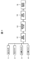
- FIG. 1 is a block diagram illustrating a configuration of an in-vehicle image processing apparatus according to the present embodiment
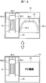
- FIG. 2 is an image diagram illustrating a configuration of an overhead image generation unit.
- the in-vehicle image processing device is realized by hardware and software in a camera device mounted on the host vehicle 10.
- the in-vehicle image processing apparatus includes an image acquisition unit 12, an overhead image generation unit 13, an image composition unit 14, and a parking frame recognition unit 15 as its internal functions.
- the image acquisition unit 12 captures through images captured by the front camera 1, the rear camera 2, the right camera 3, and the left camera 4 attached to the front, rear, right, and left sides of the vehicle 10, respectively. get.
- the overhead image generation unit 13 converts each through image acquired by the image acquisition unit 12 and generates an overhead image 25 in which the viewpoint is moved above the host vehicle 10.
- the overhead image 25 is generated using a known technique.
- the image synthesis unit 14 synthesizes the overhead image with at least one of the through images.
- the parking frame recognizing unit 15 that is an outside recognizing unit performs a process of recognizing the parking frame WL in the outside using at least one of the through image and the overhead image from the combined image combined by the image combining unit 14.
- the example shown in FIG. 2 is an image of the state where the vehicle 10 has entered the parking frame WL from the front of the host vehicle 10 captured by the cameras 1 to 4.
- the parking frame WL is formed by marking the marking lines WL1 to WL3 on the ground using white or yellow paint or the like in order to partition the size of one vehicle.
- the parking frame WL has marking lines WL1 and WL2 that divide both sides in the vehicle width direction, and a marking line WL3 that divides the vehicle longitudinal direction.
- a parking frame WL positioned around the own vehicle is displayed.
- the marking lines WL1 and WL2 and the marking line WL3 on the front side of the vehicle are projected so as to surround the host vehicle 10.
- FIG. 3 is a flowchart for explaining a method of combining images used for parking frame recognition
- FIG. 4 is an image diagram in which an overhead image and a rear camera image are combined
- FIG. 5 is an image diagram in which an overhead image and a front camera image are combined.
- the image composition unit 14 acquires shift position information of the own vehicle 10 (step S101).
- the shift position information is acquired from a control device that controls the drive system of the host vehicle 10 via CAN or the like.
- the shift position information includes information on the position of the shift position of the host vehicle 10, for example, information on the position of the shift lever in the case of a manual transmission and information on the position of a selector lever in the case of an automatic transmission.
- step S102 it is determined whether or not a reverse (reverse) R position is selected from the shift position information (step S102). If the reverse R position is selected (YES in step S102), The through image 22 of the rear camera 2 is synthesized (step S103). When a position other than the backward R is selected (NO in step S102), the overhead image 25 and the through image 21 of the front camera 1 are combined (step S104). In the example described above, the case where one through image and the overhead image are synthesized is described, but a plurality of through images and the overhead image may be synthesized.
- FIG. 6 is a flowchart for explaining an example of a parking frame recognition method
- FIG. 7 is a flowchart for explaining a parking frame recognition method using an overhead image
- FIG. 8 is a parking frame recognition method using a through image. It is a flowchart to explain.
- the parking frame recognition unit 15 first performs a first parking frame recognition process for recognizing a parking frame using the overhead image 25 (step S111), and then a second parking frame recognition for recognizing the parking frame using a through image. Processing is performed (step S112).
- a horizontal edge filter is applied to all lines (step S121), and a peak (rise / fall) is extracted (step S122). Then, only the edges where the rising and falling pairs are formed at a predetermined interval are left (step S123), grouped (step S124), and then filtered by length (step S125). Then, the coordinates of the upper and lower edges of the rising and falling edges are extracted (step S126), and two white lines (marking lines) are selected (step S127).
- step S1228 Whether the angle difference between the two selected white lines is equal to or less than a predetermined value ( ⁇ Th ⁇ max) (step S128), whether the interval between the two white lines is within a predetermined range (from ThWmin to ThWmax) (step S129), It is determined whether the deviation of the lower ends of the two white lines is within a predetermined range (ThBmin to ThBmax) (step S130). If all the conditions of these steps S129 to S130 are satisfied, the process proceeds to step S131.
- step S131 the coordinate positions of the four corner points of the parking frame WL, that is, the upper and lower ends of the white line (marking line WL2) on the left side of the vehicle and the upper and lower points of the white line (marking line WL1) on the right side of the vehicle are determined. sign up.
- step S132 it is determined whether or not all combinations have been confirmed. If confirmed (YES in step S132), the first parking frame recognition process is terminated. If not confirmed (NO in step S132). The process returns to the process of selecting two white lines (step S127), and the subsequent processes are repeated until it is determined that all combinations have been confirmed (YES in step S132).
- an image processing area is set (step S141).
- the image processing area is set so as to process only an area farther than the overhead image 25.
- a horizontal edge filter is applied to all lines (step S142), and peaks (rising and falling) are extracted (step S143).
- peaks are extracted (step S143).
- a bird's-eye view conversion is performed using camera geometry for all edge points (step S144).
- steps S123 to S132 steps S145 to S154) of the parking frame recognition method using the overhead image is performed, and the second parking frame recognition processing is ended.
- the parking frame recognition is performed using the overhead image and the through image, respectively, as compared with the one using only the overhead image, it extends to a wider distant region. Parking frame recognition can be performed.
- FIG. 9 is a flowchart for explaining another example of the parking frame recognition method.
- both the first parking frame recognition process and the second parking frame recognition process are always performed.
- both the first parking frame recognition process and the second parking frame recognition process are performed. It is good also as a structure which selects suitably either the case where the used parking frame recognition is performed, or the case where only the 1st parking frame recognition process is performed according to a condition.
- the parking frame recognition unit 15 first performs a first parking frame recognition process for recognizing a parking frame using the overhead image 25, as shown as Modification 1 in FIG. 9 (step S161). Then, information on the host vehicle speed vsp of the host vehicle 10 is obtained (step S162), and it is determined whether the host vehicle speed vsp is higher than a predetermined threshold thvsp1 (step S163).
- step S163 If it is determined that the host vehicle speed vsp is higher than the predetermined threshold thvsp1 (YES in step S163), the second parking frame recognition process using the through image is performed, and the host vehicle speed vsp is equal to or lower than the threshold thvsp1. If it is determined (NO in step S163), the process is terminated.
- both the first parking frame recognition process using the overhead image and the second parking frame recognition process using the through image are performed.
- the parking frame recognition can be performed over a far region wider than the overhead image.
- the vehicle speed is low, only the first parking frame recognition process using the overhead image is performed, and the second parking frame recognition process using the through image is not performed.
- the processing load can be reduced, and hardware resources can be used effectively, such as being used for arithmetic processing of other applications.
- FIG. 10 is a block diagram illustrating the configuration of the in-vehicle image processing apparatus according to the second embodiment
- FIG. 11 is a flowchart illustrating a display switching method
- FIG. 12 is an image diagram illustrating an example of display switching.
- the same components as those in the first embodiment are denoted by the same reference numerals, and detailed description thereof is omitted.
- a characteristic feature of the present embodiment is that the user can switch the display of the composite image.
- the in-vehicle image processing apparatus includes a display switching request acquisition unit 16 that acquires a display switching request from the user, as shown in FIG. As shown in FIG. 11, the display switching request acquisition unit 16 determines whether or not there is a user's display switching request (step S201). If there is a request (YES in step S201), the display switching request acquisition unit 16 displays it on the image composition unit 14. Switching is instructed (step S202), and when there is no request (NO in step S201), display switching is not instructed.
- the image composition unit 14 generates a composite image 31 obtained by combining the overhead image and the through image, for example, as shown in FIG.
- the synthesized image 32 that combines the overhead image and the navigation screen (the screen showing the map information and the vehicle position information) is displayed. Generate.
- These composite images 31 and 32 are selectively displayed on an in-vehicle monitor (not shown).
- the through image and the navigation screen may be combined.
- FIG. 13 is a flowchart for explaining another example of the parking frame recognition method.
- the parking frame recognition unit 15 determines whether or not the current display on the in-vehicle monitor is a composite image obtained by combining the overhead image and the through image in a state where the parking frame recognition is performed using the overhead image (step S211). (Step S212). If it is determined that the image is a composite image of the overhead image and the through image (YES in step S212), parking frame recognition is performed using the through image (step S213). On the other hand, when it is determined that the current display is not a composite image of the overhead image and the through image (NO in step S212), parking frame recognition using the overhead image is continuously performed.
- an input image of the in-vehicle image processing device is a monitor display screen.
- FIG. 14 is a block diagram illustrating the configuration of an in-vehicle image processing apparatus according to the third embodiment
- FIG. 15 is a flowchart illustrating an example of a pedestrian detection method
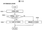
- FIG. 16 illustrates an example of a pedestrian detection method. It is a flowchart to do. Note that the same components as those in the above-described embodiments are given the same reference numerals, and detailed description thereof is omitted.
- a characteristic feature of this embodiment is that, in addition to the parking frame recognition of the first embodiment described above, pedestrian detection is performed using an overhead image and a through image.
- the in-vehicle image processing apparatus includes a pedestrian detection unit 17 that performs pedestrian detection using images captured by the in-vehicle cameras 1 to 4. As shown in FIG. 15, the pedestrian detection unit 17 performs a first pedestrian detection process (step S311) using the overhead image and a second pedestrian detection process (step S312) using the through image.
- Known techniques can be applied to the first pedestrian detection process using the overhead image and the second pedestrian detection process using the through image, for example, a first pedestrian detection process for detecting a pedestrian from the overhead image.
- a method using an optical flow described in (Patent Document 3) can be applied.
- FIG. 16 is a flowchart for explaining another example of the pedestrian detection method.
- the pedestrian detection unit 17 first acquires information on the host vehicle speed vsp (step S321), and determines whether the host vehicle speed vsp exceeds a predetermined threshold thvsp2 ( Step S322).
- step S322 If it is determined that the host vehicle speed vsp exceeds the predetermined threshold thvsp2 (YES in step S322), a second pedestrian detection process using a through image is performed, and the host vehicle speed vsp is determined to be equal to or less than the threshold thvsp2. If so (NO in step S322), the first pedestrian detection process using the overhead image is performed (step S324).
- FIG. 17 is a block diagram illustrating the configuration of an in-vehicle image processing apparatus according to the fourth embodiment
- FIG. 18 is a flowchart illustrating a scheduling method
- FIG. 19 is a diagram illustrating an example of CPU usage allocation. Note that the same components as those in the above-described embodiments are given the same reference numerals, and detailed description thereof is omitted.
- a characteristic feature of this embodiment is that the scheduling unit 18 is added to the configuration of the third embodiment.
- the in-vehicle image processing apparatus includes a scheduling unit 18 that determines whether or not to execute the external recognition process by the external recognition unit according to the vehicle speed.
- the scheduling unit 18 acquires information on the host vehicle speed vsp (step S411), and determines whether the host vehicle speed vsp is equal to or lower than a predetermined threshold th_vlow (step S412). If it is determined that the host vehicle speed vsp is equal to or less than the predetermined threshold th_vlow (YES in step S412), both the parking frame recognition process and the pedestrian detection process are performed (step S413). On the other hand, when it is determined that the host vehicle speed vsp is higher than the threshold th_vlow (NO in step S412), only the parking frame recognition process is performed (step S414).
- the hardware CPU of the in-vehicle image processing apparatus has, for example, a first image processing circuit configured by a dedicated chip for image processing and a second image processing circuit configured by a versatile chip.
- the scheduling unit 18 distributes the usage of the first image processing circuit and the second image processing circuit according to the vehicle speed condition.
- both the parking frame recognition process and the pedestrian detection process are performed in step S413, but all the pedestrian detection processes are performed in the first image processing circuit. (100%) is performed and the second image processing circuit is used and distributed so that all (100%) of the parking frame recognition processing is performed.
- step S414 if the host vehicle speed vsp is faster than the threshold th_vlow, only parking frame recognition is performed in step S414, but the first image processing circuit performs 50% of the parking frame recognition processing, and the second image processing circuit causes the parking frame to be recognized. The usage is distributed so that the remaining 50% of the recognition processing is performed.
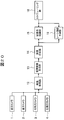
- FIG. 20 is a block diagram illustrating the configuration of an in-vehicle image processing apparatus according to the fifth embodiment
- FIG. 21 is a flowchart illustrating a lane departure prediction method
- FIG. 22 is an image diagram illustrating a lane departure prediction method.
- a characteristic feature of this embodiment is that a lane departure prediction unit 19 is provided instead of the pedestrian detection unit 17 of the fourth embodiment.
- the in-vehicle image processing apparatus has a lane departure prediction unit 19 as shown in FIG.
- the lane departure prediction unit 19 performs a lane departure prediction process for predicting that the host vehicle 10 deviates from the traveling lane while traveling.
- the lane departure prediction unit 19 performs lane recognition using a through image (step S511), and projects the result onto an overhead image (step S512).
- a lane recognition method using a through image can be performed using a known technique.
- the departure from the traveling lane of the host vehicle is predicted using the overhead image (step S513). For example, it is predicted that there is a possibility of deviating from the traveling lane when the vehicle 10 is traveling to a predetermined distance with respect to the traveling lane while traveling.
- step S511 By the lane recognition in step S511, as shown in FIG. 22, two traveling lanes WL5 and WL6 extending along the traveling direction of the vehicle 10 are recognized on the through image 22 of the composite image 31.
- step S512 the traveling lanes WL5 and WL6 recognized in the through image 22 are projected on the overhead image 25 of the composite image 31 ', and lane departure prediction using the overhead image 25 is performed in step S513.
- the overhead image 25 is easier to handle in terms of image processing than the through image 22. Therefore, the lane departure can be predicted more quickly and accurately when the overhead image 25 is used than when the through image 22 is used.
- FIG. 23 is a flowchart illustrating a scheduling method
- FIG. 24 is a diagram illustrating an example of CPU usage allocation.
- the scheduling unit 18 acquires information on the host vehicle speed vsp (step S521), and determines whether the host vehicle speed vsp is equal to or lower than a predetermined low speed threshold th_vlow (step S522). If it is determined that the host vehicle speed vsp is equal to or lower than the low speed threshold th_vlow (YES in step S522), only the parking frame recognition process is performed (step S523).
- step S524 it is determined whether the host vehicle speed vsp is equal to or lower than the high speed threshold th_vhigh (step S524). If it is determined that the host vehicle speed vsp is equal to or less than the high speed threshold th_vhigh (YES in step S524), both the parking frame recognition process and the lane departure prediction process are performed (step S525). On the other hand, when it is determined that the host vehicle speed vsp is higher than the high speed threshold th_vhigh (NO in step S524), only the lane departure prediction process is performed (step S526).
- the hardware CPU of the in-vehicle image processing apparatus has, for example, a first image processing circuit configured by a dedicated chip for image processing and a second image processing circuit configured by a versatile chip.
- the scheduling unit 18 distributes the usage of the first image processing circuit and the second image processing circuit according to the vehicle speed condition.
- step S523 when the host vehicle speed vsp is equal to or lower than the low speed threshold th_vlow, only the parking frame recognition process is performed in step S523, but the first image processing circuit performs 50% of the parking frame recognition process, The usage distribution is performed so that the remaining 50% of the parking frame recognition is performed by the two-image processing circuit.
- both parking frame recognition and lane departure prediction are performed in step S525, but the first image processing circuit performs the parking frame detection process. All (100%) is performed, and the second image processing circuit is allocated so that all (100%) lane departure prediction processing is performed.
- step S526 If the host vehicle speed vsp is higher than the high speed threshold th_vhigh, only the lane departure determination is performed in step S526, but the first image processing circuit performs 50% of the lane departure determination, and the second image processing circuit causes the lane departure determination. The usage is distributed so that the remaining 50% of the determination is performed.
- the present invention is not limited to the above-described embodiments, and various designs can be made without departing from the spirit of the present invention described in the claims. It can be changed.
- the above-described embodiment has been described in detail for easy understanding of the present invention, and is not necessarily limited to one having all the configurations described.
- a part of the configuration of an embodiment can be replaced with the configuration of another embodiment, and the configuration of another embodiment can be added to the configuration of an embodiment.
Landscapes
- Engineering & Computer Science (AREA)
- Multimedia (AREA)
- Physics & Mathematics (AREA)
- General Physics & Mathematics (AREA)
- Mechanical Engineering (AREA)
- Theoretical Computer Science (AREA)
- Human Computer Interaction (AREA)
- Image Processing (AREA)
- Image Analysis (AREA)
- Traffic Control Systems (AREA)
- Closed-Circuit Television Systems (AREA)
Abstract
Description
図1は、本実施の形態にかかわる車載画像処理装置の構成を説明するブロック図、図2は、俯瞰画像生成部の構成を説明するイメージ図である。
次に、本発明の第2実施の形態について図10から図13を参照しつつ以下に説明する。
次に、本発明の第3実施の形態について図14から図16を参照しつつ以下に説明する。
次に、本発明の第4実施の形態について図17から図19を参照しつつ以下に説明する。
次に、本発明の第5実施の形態について図20から図24を参照しつつ以下に説明する。
10 自車(車両)
12 画像取得部
13 俯瞰画像生成部
14 画像合成部
15 駐車枠認識部
16 表示切替要求取得部
17 歩行者検知部
18 スケジューリング部
19 レーン逸脱予測部
21~24 スルー画像
25 俯瞰画像
WL 駐車枠
WL1~WL3 標示線
WL5、WL6 走行ライン
Claims (6)
- 車両の前方、後方、側方にそれぞれ配置されたカメラで撮像したスルー画像を取得する画像取得部と、
該取得した各スルー画像を変換して俯瞰画像を生成する俯瞰画像生成部と、
前記スルー画像と前記俯瞰画像の少なくとも一方を用いて駐車枠を認識する駐車枠認識処理を行う駐車枠認識部と、を有し、
前記駐車枠認識部は、前記俯瞰画像を用いて、該俯瞰画像の所定範囲内の駐車枠を認識する第1駐車枠認識処理と、前記スルー画像を用いて、前記俯瞰画像の所定範囲内よりも遠方の領域の駐車枠を認識する第2駐車枠認識処理を行うことを特徴とする車載画像処理装置。 - 前記駐車枠認識部は、自車速が予め設定された閾値以下の場合、前記第1駐車枠認識処理を行い、自車速が前記閾値よりも高い場合、前記第1駐車枠認識処理と前記第2駐車枠認識処理を行うことを特徴とする請求項1に記載の車載画像処理装置。
- ユーザからの表示切替要求により前記俯瞰画像と前記スルー画像とを含む合成画像を選択表示可能な車内モニターを有し、
前記駐車枠認識部は、前記第1駐車枠認識処理を行っている状態で、前記車内モニターに前記合成画像が選択表示された場合に、前記第1駐車枠認識処理に替えて前記第2駐車枠認識処理を行うことを特徴とする請求項1に記載の車載画像処理装置。 - 前記スルー画像と前記俯瞰画像の少なくとも一方を用いて歩行者を検知する歩行者検知処理を行う歩行者検知部と、
前記自車速に応じて前記駐車枠認識部による駐車枠認識処理及び前記歩行者検知部による歩行者検知処理を実行するか否かを決定するスケジューリング部と、を有し、
前記スケジューリング部は、
前記自車速が予め設定された閾値以下の場合に、前記駐車枠認識部による駐車枠認識処理と、前記歩行者検知部による歩行者検知処理の両方を行わせ、
前記自車速が前記閾値よりも高い場合に、前記駐車枠認識部による駐車枠認識処理のみを行わせることを特徴とする請求項1に記載の車載画像処理装置。 - 第1画像処理回路と第2画像処理回路を有し、
前記スケジューリング部は、
前記自車速が前記閾値以下の場合に、前記第1画像処理回路と前記第2画像処理回路のいずれか一方により、前記歩行者検知部による歩行者検知処理を行わせ、前記第1画像処理回路と前記第2画像処理回路の他方により、前記駐車枠認識部による駐車枠認識処理を行わせ、
前記自車速が前記閾値よりも高い場合に、前記第1画像処理回路により前記駐車枠認識部による前記駐車枠認識処理の一部を行わせ、前記第2画像処理回路により前記駐車枠認識部による前記駐車枠認識処理の残りを行わせることを特徴とする請求項4に記載の車載画像処理装置。 - 前記スルー画像と前記俯瞰画像の少なくとも一方を用いて自車走行レーンを認識するレーン認識部と、
前記自車速に応じて前記駐車枠認識部による駐車枠認識処理及び前記レーン認識部によるレーン認識処理を実行するか否かを決定するスケジューリング部と、を有し、
前記スケジューリング部は、
前記自車速が予め設定された第1閾値以下のときは前記駐車枠認識部による駐車枠認識処理のみを行わせ、
前記自車速が前記第1閾値よりも高く、かつ、予め設定された第2閾値以下のときは、前記駐車枠認識部による駐車枠認識処理と、前記レーン認識部によるレーン認識処理の両方を行わせ、
前記自車速が前記第2閾値よりも高い場合に、前記レーン認識部によるレーン認識処理のみを行わせることを特徴とする請求項1に記載の車載画像処理装置。
Priority Applications (4)
| Application Number | Priority Date | Filing Date | Title |
|---|---|---|---|
| EP13859419.7A EP2927863B1 (en) | 2012-11-27 | 2013-11-27 | Vehicle-mounted image processing device |
| CN201380061842.1A CN104871204B (zh) | 2012-11-27 | 2013-11-27 | 车载图像处理装置 |
| US14/647,398 US9715633B2 (en) | 2012-11-27 | 2013-11-27 | Vehicle-mounted image processing device |
| JP2014549863A JP5921715B2 (ja) | 2012-11-27 | 2013-11-27 | 車載画像処理装置 |
Applications Claiming Priority (2)
| Application Number | Priority Date | Filing Date | Title |
|---|---|---|---|
| JP2012258984 | 2012-11-27 | ||
| JP2012-258984 | 2012-11-27 |
Publications (1)
| Publication Number | Publication Date |
|---|---|
| WO2014084256A1 true WO2014084256A1 (ja) | 2014-06-05 |
Family
ID=50827888
Family Applications (1)
| Application Number | Title | Priority Date | Filing Date |
|---|---|---|---|
| PCT/JP2013/081898 Ceased WO2014084256A1 (ja) | 2012-11-27 | 2013-11-27 | 車載画像処理装置 |
Country Status (5)
| Country | Link |
|---|---|
| US (1) | US9715633B2 (ja) |
| EP (1) | EP2927863B1 (ja) |
| JP (1) | JP5921715B2 (ja) |
| CN (1) | CN104871204B (ja) |
| WO (1) | WO2014084256A1 (ja) |
Cited By (1)
| Publication number | Priority date | Publication date | Assignee | Title |
|---|---|---|---|---|
| JP2016031648A (ja) * | 2014-07-29 | 2016-03-07 | 株式会社デンソー | 車載機器 |
Families Citing this family (15)
| Publication number | Priority date | Publication date | Assignee | Title |
|---|---|---|---|---|
| JP6307895B2 (ja) * | 2014-01-23 | 2018-04-11 | トヨタ自動車株式会社 | 車両用周辺監視装置 |
| DE102014107235A1 (de) * | 2014-05-22 | 2015-11-26 | Dr. Ing. H.C. F. Porsche Aktiengesellschaft | Verfahren zur Darstellung einer Fahrzeugumgebung auf einer Anzeigevorrichtung; eine Anzeigevorrichtung; ein System aus einer Mehrzahl an Bilderfassungseinheiten und einer Anzeigevorrichtung; ein Computerprogramm |
| JP6206395B2 (ja) * | 2014-12-26 | 2017-10-04 | トヨタ自動車株式会社 | 電子ミラー装置 |
| US10160437B2 (en) * | 2016-02-29 | 2018-12-25 | Magna Electronics Inc. | Vehicle control system with reverse assist |
| JP6572862B2 (ja) * | 2016-10-14 | 2019-09-11 | 株式会社デンソー | 表示制御装置 |
| EP3389026A1 (en) * | 2017-04-12 | 2018-10-17 | Volvo Car Corporation | Apparatus and method for road vehicle driver assistance |
| JP7069692B2 (ja) * | 2017-12-20 | 2022-05-18 | トヨタ自動車株式会社 | 画像表示装置 |
| DE102018215055A1 (de) * | 2018-09-05 | 2020-03-05 | Bayerische Motoren Werke Aktiengesellschaft | Verfahren zum Bestimmen einer Spurwechselangabe eines Fahrzeugs, ein computerlesbares Speichermedium und ein Fahrzeug |
| JP7288793B2 (ja) * | 2019-04-25 | 2023-06-08 | フォルシアクラリオン・エレクトロニクス株式会社 | 画像処理装置及び画像処理方法 |
| US11037328B1 (en) | 2019-12-31 | 2021-06-15 | Lyft, Inc. | Overhead view image generation |
| US11288522B2 (en) | 2019-12-31 | 2022-03-29 | Woven Planet North America, Inc. | Generating training data from overhead view images |
| US11244500B2 (en) | 2019-12-31 | 2022-02-08 | Woven Planet North America, Inc. | Map feature extraction using overhead view images |
| JP7482054B2 (ja) | 2020-02-27 | 2024-05-13 | フォルシアクラリオン・エレクトロニクス株式会社 | 画像処理装置及び画像処理方法 |
| CN115210790B (zh) * | 2020-08-28 | 2024-11-15 | Jvc建伍株式会社 | 目标识别控制装置以及目标识别方法 |
| US12254706B2 (en) * | 2021-11-05 | 2025-03-18 | Vinai Artificial Intelligence Application And Research Joint Stock Company | Parking slot detection method and system |
Citations (6)
| Publication number | Priority date | Publication date | Assignee | Title |
|---|---|---|---|---|
| JP2004254219A (ja) * | 2003-02-21 | 2004-09-09 | Denso Corp | 車両周辺画像処理装置及びプログラム並びに記録媒体 |
| JP2007161193A (ja) * | 2005-12-16 | 2007-06-28 | Denso Corp | 駐車支援装置 |
| JP2010146478A (ja) | 2008-12-22 | 2010-07-01 | Toyota Motor Corp | 物体検出装置 |
| JP2011030140A (ja) | 2009-07-29 | 2011-02-10 | Hitachi Automotive Systems Ltd | 外界認識装置 |
| JP2011077772A (ja) | 2009-09-30 | 2011-04-14 | Hitachi Automotive Systems Ltd | 周囲確認支援装置 |
| WO2011162108A1 (ja) * | 2010-06-25 | 2011-12-29 | 日産自動車株式会社 | 駐車支援制御装置及び制御方法 |
Family Cites Families (25)
| Publication number | Priority date | Publication date | Assignee | Title |
|---|---|---|---|---|
| US5961571A (en) * | 1994-12-27 | 1999-10-05 | Siemens Corporated Research, Inc | Method and apparatus for automatically tracking the location of vehicles |
| US7366595B1 (en) * | 1999-06-25 | 2008-04-29 | Seiko Epson Corporation | Vehicle drive assist system |
| US6734896B2 (en) * | 2000-04-28 | 2004-05-11 | Matsushita Electric Industrial Co., Ltd. | Image processor and monitoring system |
| JP3297040B1 (ja) * | 2001-04-24 | 2002-07-02 | 松下電器産業株式会社 | 車載カメラの画像合成表示方法及びその装置 |
| JP4156214B2 (ja) * | 2001-06-13 | 2008-09-24 | 株式会社デンソー | 車両周辺画像処理装置及び記録媒体 |
| ES2258399B1 (es) * | 2005-02-04 | 2007-11-16 | Fico Mirrors, S.A. | Metodo y sistema para mejorar la supervision de un ambiente exterior de un vehiculo automovil. |
| DE102005005969A1 (de) * | 2005-02-10 | 2006-08-24 | Robert Bosch Gmbh | Verfahren und System zur Unterstützung eines semiautonomen Parkvorgangs von Kr aftfahrzeugen |
| US7415134B2 (en) * | 2005-05-17 | 2008-08-19 | Honda Motor Co., Ltd. | Traffic lane marking line recognition system for vehicle |
| KR101143176B1 (ko) * | 2006-09-14 | 2012-05-08 | 주식회사 만도 | 조감도를 이용한 주차구획 인식 방법, 장치 및 그를 이용한주차 보조 시스템 |
| KR20090088210A (ko) * | 2008-02-14 | 2009-08-19 | 주식회사 만도 | 두 개의 기준점을 이용한 목표주차위치 검출 방법과 장치및 그를 이용한 주차 보조 시스템 |
| JP5068779B2 (ja) * | 2009-02-27 | 2012-11-07 | 現代自動車株式会社 | 車両周囲俯瞰画像表示装置及び方法 |
| JP5210233B2 (ja) * | 2009-04-14 | 2013-06-12 | 日立オートモティブシステムズ株式会社 | 車両用外界認識装置及びそれを用いた車両システム |
| JP5627253B2 (ja) * | 2009-05-29 | 2014-11-19 | 富士通テン株式会社 | 画像処理装置、電子装置、および、画像処理方法 |
| JP5372680B2 (ja) * | 2009-09-24 | 2013-12-18 | 日立オートモティブシステムズ株式会社 | 障害物検知装置 |
| JP5401344B2 (ja) * | 2010-01-28 | 2014-01-29 | 日立オートモティブシステムズ株式会社 | 車両用外界認識装置 |
| US8948990B2 (en) * | 2010-06-25 | 2015-02-03 | Nissan Motor Co., Ltd. | Parking assist control apparatus and control method |
| JP5472026B2 (ja) * | 2010-06-29 | 2014-04-16 | トヨタ自動車株式会社 | 駐車支援装置 |
| US9264672B2 (en) * | 2010-12-22 | 2016-02-16 | Magna Mirrors Of America, Inc. | Vision display system for vehicle |
| JP5603835B2 (ja) * | 2011-06-27 | 2014-10-08 | クラリオン株式会社 | 車両周囲監視装置 |
| TW201344648A (zh) * | 2012-04-30 | 2013-11-01 | Tung Thih Electronic Co Ltd | 行車監控系統與行車監控方法 |
| US10089537B2 (en) * | 2012-05-18 | 2018-10-02 | Magna Electronics Inc. | Vehicle vision system with front and rear camera integration |
| US9467687B2 (en) * | 2012-07-03 | 2016-10-11 | Clarion Co., Ltd. | Vehicle-mounted environment recognition device |
| JP6393189B2 (ja) * | 2012-11-27 | 2018-09-19 | クラリオン株式会社 | 車載画像処理装置 |
| US9892493B2 (en) * | 2014-04-21 | 2018-02-13 | Texas Instruments Incorporated | Method, apparatus and system for performing geometric calibration for surround view camera solution |
| CN104464375B (zh) * | 2014-11-20 | 2017-05-31 | 长安大学 | 一种识别车辆高速转弯的方法 |
-
2013
- 2013-11-27 CN CN201380061842.1A patent/CN104871204B/zh not_active Expired - Fee Related
- 2013-11-27 EP EP13859419.7A patent/EP2927863B1/en active Active
- 2013-11-27 WO PCT/JP2013/081898 patent/WO2014084256A1/ja not_active Ceased
- 2013-11-27 JP JP2014549863A patent/JP5921715B2/ja not_active Expired - Fee Related
- 2013-11-27 US US14/647,398 patent/US9715633B2/en active Active
Patent Citations (6)
| Publication number | Priority date | Publication date | Assignee | Title |
|---|---|---|---|---|
| JP2004254219A (ja) * | 2003-02-21 | 2004-09-09 | Denso Corp | 車両周辺画像処理装置及びプログラム並びに記録媒体 |
| JP2007161193A (ja) * | 2005-12-16 | 2007-06-28 | Denso Corp | 駐車支援装置 |
| JP2010146478A (ja) | 2008-12-22 | 2010-07-01 | Toyota Motor Corp | 物体検出装置 |
| JP2011030140A (ja) | 2009-07-29 | 2011-02-10 | Hitachi Automotive Systems Ltd | 外界認識装置 |
| JP2011077772A (ja) | 2009-09-30 | 2011-04-14 | Hitachi Automotive Systems Ltd | 周囲確認支援装置 |
| WO2011162108A1 (ja) * | 2010-06-25 | 2011-12-29 | 日産自動車株式会社 | 駐車支援制御装置及び制御方法 |
Non-Patent Citations (1)
| Title |
|---|
| MASAHIRO KIYOHARA ET AL.: "Sharyo Shuhen Kanshi no Tameno Idotai Kenshutsu Gijutsu no Kaihatsu", EIZO JOHO INDUSTRIAL, vol. 44, no. 5, 1 May 2012 (2012-05-01), pages 45 - 51, XP008179512 * |
Cited By (1)
| Publication number | Priority date | Publication date | Assignee | Title |
|---|---|---|---|---|
| JP2016031648A (ja) * | 2014-07-29 | 2016-03-07 | 株式会社デンソー | 車載機器 |
Also Published As
| Publication number | Publication date |
|---|---|
| US9715633B2 (en) | 2017-07-25 |
| JP5921715B2 (ja) | 2016-05-24 |
| EP2927863A1 (en) | 2015-10-07 |
| CN104871204A (zh) | 2015-08-26 |
| CN104871204B (zh) | 2018-01-26 |
| JPWO2014084256A1 (ja) | 2017-01-05 |
| EP2927863B1 (en) | 2020-03-04 |
| US20150310285A1 (en) | 2015-10-29 |
| EP2927863A4 (en) | 2016-08-24 |
Similar Documents
| Publication | Publication Date | Title |
|---|---|---|
| JP5921715B2 (ja) | 車載画像処理装置 | |
| RU2704773C1 (ru) | Способ и устройство управления отображением | |
| EP3400556B1 (en) | Systems and methods for estimating future paths | |
| US8305431B2 (en) | Device intended to support the driving of a motor vehicle comprising a system capable of capturing stereoscopic images | |
| JP6313646B2 (ja) | 外界認識装置 | |
| US10896542B2 (en) | Moving body image generation recording display device and program product | |
| WO2017145543A1 (ja) | 情報処理装置 | |
| JP2019090627A (ja) | 表示システム、表示方法、およびプログラム | |
| JP2023165721A (ja) | 表示制御装置 | |
| WO2019092846A1 (ja) | 表示システム、表示方法、およびプログラム | |
| JP2018136695A (ja) | 駐車支援装置 | |
| JP6277933B2 (ja) | 表示制御装置、表示システム | |
| JP7837890B2 (ja) | 撮像装置、画像処理方法及び画像処理プログラム | |
| WO2019003736A1 (ja) | 画像処理装置 | |
| JP2022121370A (ja) | 表示制御装置及び表示制御プログラム | |
| JP2020140603A (ja) | 表示制御装置、表示制御方法、および表示制御プログラム | |
| KR102023863B1 (ko) | 이동체 주위 표시 방법 및 이동체 주위 표시 장치 | |
| JP6080735B2 (ja) | 運転支援装置 | |
| JP6148848B2 (ja) | 車載画像処理装置 | |
| JP7075273B2 (ja) | 駐車支援装置 | |
| JP2014107696A (ja) | 車載画像処理装置 | |
| JP7619336B2 (ja) | 表示制御装置、表示制御用コンピュータプログラム及び表示制御方法 | |
| JP6349890B2 (ja) | 運転支援装置 | |
| US10926700B2 (en) | Image processing device | |
| EP3865815A1 (en) | Vehicle-mounted system |
Legal Events
| Date | Code | Title | Description |
|---|---|---|---|
| 121 | Ep: the epo has been informed by wipo that ep was designated in this application |
Ref document number: 13859419 Country of ref document: EP Kind code of ref document: A1 |
|
| DPE1 | Request for preliminary examination filed after expiration of 19th month from priority date (pct application filed from 20040101) | ||
| ENP | Entry into the national phase |
Ref document number: 2014549863 Country of ref document: JP Kind code of ref document: A |
|
| WWE | Wipo information: entry into national phase |
Ref document number: 14647398 Country of ref document: US |
|
| NENP | Non-entry into the national phase |
Ref country code: DE |
|
| WWE | Wipo information: entry into national phase |
Ref document number: 2013859419 Country of ref document: EP |