WO2014084283A1 - 車両用シート - Google Patents
車両用シート Download PDFInfo
- Publication number
- WO2014084283A1 WO2014084283A1 PCT/JP2013/081973 JP2013081973W WO2014084283A1 WO 2014084283 A1 WO2014084283 A1 WO 2014084283A1 JP 2013081973 W JP2013081973 W JP 2013081973W WO 2014084283 A1 WO2014084283 A1 WO 2014084283A1
- Authority
- WO
- WIPO (PCT)
- Prior art keywords
- seat
- plate
- seated person
- width direction
- air cell
- Prior art date
- Legal status (The legal status is an assumption and is not a legal conclusion. Google has not performed a legal analysis and makes no representation as to the accuracy of the status listed.)
- Ceased
Links
Images















Classifications
-
- B—PERFORMING OPERATIONS; TRANSPORTING
- B60—VEHICLES IN GENERAL
- B60N—SEATS SPECIALLY ADAPTED FOR VEHICLES; VEHICLE PASSENGER ACCOMMODATION NOT OTHERWISE PROVIDED FOR
- B60N2/00—Seats specially adapted for vehicles; Arrangement or mounting of seats in vehicles
- B60N2/62—Thigh-rests
-
- B—PERFORMING OPERATIONS; TRANSPORTING
- B60—VEHICLES IN GENERAL
- B60N—SEATS SPECIALLY ADAPTED FOR VEHICLES; VEHICLE PASSENGER ACCOMMODATION NOT OTHERWISE PROVIDED FOR
- B60N2/00—Seats specially adapted for vehicles; Arrangement or mounting of seats in vehicles
- B60N2/64—Back-rests or cushions
- B60N2/643—Back-rests or cushions shape of the back-rests
-
- B—PERFORMING OPERATIONS; TRANSPORTING
- B60—VEHICLES IN GENERAL
- B60N—SEATS SPECIALLY ADAPTED FOR VEHICLES; VEHICLE PASSENGER ACCOMMODATION NOT OTHERWISE PROVIDED FOR
- B60N2/00—Seats specially adapted for vehicles; Arrangement or mounting of seats in vehicles
- B60N2/002—Seats provided with an occupancy detection means mounted therein or thereon
- B60N2/0021—Seats provided with an occupancy detection means mounted therein or thereon characterised by the type of sensor or measurement
- B60N2/0024—Seats provided with an occupancy detection means mounted therein or thereon characterised by the type of sensor or measurement for identifying, categorising or investigation of the occupant or object on the seat
- B60N2/0025—Seats provided with an occupancy detection means mounted therein or thereon characterised by the type of sensor or measurement for identifying, categorising or investigation of the occupant or object on the seat by using weight measurement
-
- B—PERFORMING OPERATIONS; TRANSPORTING
- B60—VEHICLES IN GENERAL
- B60N—SEATS SPECIALLY ADAPTED FOR VEHICLES; VEHICLE PASSENGER ACCOMMODATION NOT OTHERWISE PROVIDED FOR
- B60N2/00—Seats specially adapted for vehicles; Arrangement or mounting of seats in vehicles
- B60N2/002—Seats provided with an occupancy detection means mounted therein or thereon
- B60N2/0021—Seats provided with an occupancy detection means mounted therein or thereon characterised by the type of sensor or measurement
- B60N2/0024—Seats provided with an occupancy detection means mounted therein or thereon characterised by the type of sensor or measurement for identifying, categorising or investigation of the occupant or object on the seat
- B60N2/0027—Seats provided with an occupancy detection means mounted therein or thereon characterised by the type of sensor or measurement for identifying, categorising or investigation of the occupant or object on the seat for detecting the position of the occupant or of occupant's body part
- B60N2/0028—Seats provided with an occupancy detection means mounted therein or thereon characterised by the type of sensor or measurement for identifying, categorising or investigation of the occupant or object on the seat for detecting the position of the occupant or of occupant's body part of a body part, e.g. of an arm or a leg
-
- B—PERFORMING OPERATIONS; TRANSPORTING
- B60—VEHICLES IN GENERAL
- B60N—SEATS SPECIALLY ADAPTED FOR VEHICLES; VEHICLE PASSENGER ACCOMMODATION NOT OTHERWISE PROVIDED FOR
- B60N2/00—Seats specially adapted for vehicles; Arrangement or mounting of seats in vehicles
- B60N2/002—Seats provided with an occupancy detection means mounted therein or thereon
- B60N2/0021—Seats provided with an occupancy detection means mounted therein or thereon characterised by the type of sensor or measurement
- B60N2/003—Seats provided with an occupancy detection means mounted therein or thereon characterised by the type of sensor or measurement characterised by the sensor mounting location in or on the seat
-
- B—PERFORMING OPERATIONS; TRANSPORTING
- B60—VEHICLES IN GENERAL
- B60N—SEATS SPECIALLY ADAPTED FOR VEHICLES; VEHICLE PASSENGER ACCOMMODATION NOT OTHERWISE PROVIDED FOR
- B60N2/00—Seats specially adapted for vehicles; Arrangement or mounting of seats in vehicles
- B60N2/02—Seats specially adapted for vehicles; Arrangement or mounting of seats in vehicles the seat or part thereof being movable, e.g. adjustable
- B60N2/0284—Adjustable seat-cushion length
-
- B—PERFORMING OPERATIONS; TRANSPORTING
- B60—VEHICLES IN GENERAL
- B60N—SEATS SPECIALLY ADAPTED FOR VEHICLES; VEHICLE PASSENGER ACCOMMODATION NOT OTHERWISE PROVIDED FOR
- B60N2/00—Seats specially adapted for vehicles; Arrangement or mounting of seats in vehicles
- B60N2/24—Seats specially adapted for vehicles; Arrangement or mounting of seats in vehicles for particular purposes or particular vehicles
- B60N2/42—Seats specially adapted for vehicles; Arrangement or mounting of seats in vehicles for particular purposes or particular vehicles the seat constructed to protect the occupant from the effect of abnormal g-forces, e.g. crash or safety seats
-
- B—PERFORMING OPERATIONS; TRANSPORTING
- B60—VEHICLES IN GENERAL
- B60N—SEATS SPECIALLY ADAPTED FOR VEHICLES; VEHICLE PASSENGER ACCOMMODATION NOT OTHERWISE PROVIDED FOR
- B60N2/00—Seats specially adapted for vehicles; Arrangement or mounting of seats in vehicles
- B60N2/24—Seats specially adapted for vehicles; Arrangement or mounting of seats in vehicles for particular purposes or particular vehicles
- B60N2/42—Seats specially adapted for vehicles; Arrangement or mounting of seats in vehicles for particular purposes or particular vehicles the seat constructed to protect the occupant from the effect of abnormal g-forces, e.g. crash or safety seats
- B60N2/4207—Seats specially adapted for vehicles; Arrangement or mounting of seats in vehicles for particular purposes or particular vehicles the seat constructed to protect the occupant from the effect of abnormal g-forces, e.g. crash or safety seats characterised by the direction of the g-forces
- B60N2/4214—Seats specially adapted for vehicles; Arrangement or mounting of seats in vehicles for particular purposes or particular vehicles the seat constructed to protect the occupant from the effect of abnormal g-forces, e.g. crash or safety seats characterised by the direction of the g-forces longitudinal
- B60N2/4228—Seats specially adapted for vehicles; Arrangement or mounting of seats in vehicles for particular purposes or particular vehicles the seat constructed to protect the occupant from the effect of abnormal g-forces, e.g. crash or safety seats characterised by the direction of the g-forces longitudinal due to impact coming from the rear
-
- B—PERFORMING OPERATIONS; TRANSPORTING
- B60—VEHICLES IN GENERAL
- B60N—SEATS SPECIALLY ADAPTED FOR VEHICLES; VEHICLE PASSENGER ACCOMMODATION NOT OTHERWISE PROVIDED FOR
- B60N2/00—Seats specially adapted for vehicles; Arrangement or mounting of seats in vehicles
- B60N2/24—Seats specially adapted for vehicles; Arrangement or mounting of seats in vehicles for particular purposes or particular vehicles
- B60N2/42—Seats specially adapted for vehicles; Arrangement or mounting of seats in vehicles for particular purposes or particular vehicles the seat constructed to protect the occupant from the effect of abnormal g-forces, e.g. crash or safety seats
- B60N2/4207—Seats specially adapted for vehicles; Arrangement or mounting of seats in vehicles for particular purposes or particular vehicles the seat constructed to protect the occupant from the effect of abnormal g-forces, e.g. crash or safety seats characterised by the direction of the g-forces
- B60N2/4235—Seats specially adapted for vehicles; Arrangement or mounting of seats in vehicles for particular purposes or particular vehicles the seat constructed to protect the occupant from the effect of abnormal g-forces, e.g. crash or safety seats characterised by the direction of the g-forces transversal
-
- B—PERFORMING OPERATIONS; TRANSPORTING
- B60—VEHICLES IN GENERAL
- B60N—SEATS SPECIALLY ADAPTED FOR VEHICLES; VEHICLE PASSENGER ACCOMMODATION NOT OTHERWISE PROVIDED FOR
- B60N2/00—Seats specially adapted for vehicles; Arrangement or mounting of seats in vehicles
- B60N2/24—Seats specially adapted for vehicles; Arrangement or mounting of seats in vehicles for particular purposes or particular vehicles
- B60N2/42—Seats specially adapted for vehicles; Arrangement or mounting of seats in vehicles for particular purposes or particular vehicles the seat constructed to protect the occupant from the effect of abnormal g-forces, e.g. crash or safety seats
- B60N2/427—Seats or parts thereof displaced during a crash
- B60N2/42727—Seats or parts thereof displaced during a crash involving substantially rigid displacement
- B60N2/42754—Seats or parts thereof displaced during a crash involving substantially rigid displacement of the cushion
-
- B—PERFORMING OPERATIONS; TRANSPORTING
- B60—VEHICLES IN GENERAL
- B60N—SEATS SPECIALLY ADAPTED FOR VEHICLES; VEHICLE PASSENGER ACCOMMODATION NOT OTHERWISE PROVIDED FOR
- B60N2/00—Seats specially adapted for vehicles; Arrangement or mounting of seats in vehicles
- B60N2/64—Back-rests or cushions
- B60N2/66—Lumbar supports
-
- B—PERFORMING OPERATIONS; TRANSPORTING
- B60—VEHICLES IN GENERAL
- B60N—SEATS SPECIALLY ADAPTED FOR VEHICLES; VEHICLE PASSENGER ACCOMMODATION NOT OTHERWISE PROVIDED FOR
- B60N2/00—Seats specially adapted for vehicles; Arrangement or mounting of seats in vehicles
- B60N2/68—Seat frames
-
- B—PERFORMING OPERATIONS; TRANSPORTING
- B60—VEHICLES IN GENERAL
- B60N—SEATS SPECIALLY ADAPTED FOR VEHICLES; VEHICLE PASSENGER ACCOMMODATION NOT OTHERWISE PROVIDED FOR
- B60N2/00—Seats specially adapted for vehicles; Arrangement or mounting of seats in vehicles
- B60N2/80—Head-rests
-
- B—PERFORMING OPERATIONS; TRANSPORTING
- B60—VEHICLES IN GENERAL
- B60N—SEATS SPECIALLY ADAPTED FOR VEHICLES; VEHICLE PASSENGER ACCOMMODATION NOT OTHERWISE PROVIDED FOR
- B60N2/00—Seats specially adapted for vehicles; Arrangement or mounting of seats in vehicles
- B60N2/90—Details or parts not otherwise provided for
- B60N2/914—Hydro-pneumatic adjustments of the shape
-
- B—PERFORMING OPERATIONS; TRANSPORTING
- B60—VEHICLES IN GENERAL
- B60N—SEATS SPECIALLY ADAPTED FOR VEHICLES; VEHICLE PASSENGER ACCOMMODATION NOT OTHERWISE PROVIDED FOR
- B60N2/00—Seats specially adapted for vehicles; Arrangement or mounting of seats in vehicles
- B60N2/90—Details or parts not otherwise provided for
- B60N2/986—Side-rests
-
- B—PERFORMING OPERATIONS; TRANSPORTING
- B60—VEHICLES IN GENERAL
- B60N—SEATS SPECIALLY ADAPTED FOR VEHICLES; VEHICLE PASSENGER ACCOMMODATION NOT OTHERWISE PROVIDED FOR
- B60N2210/00—Sensor types, e.g. for passenger detection systems or for controlling seats
- B60N2210/10—Field detection presence sensors
- B60N2210/12—Capacitive; Electric field
-
- B—PERFORMING OPERATIONS; TRANSPORTING
- B60—VEHICLES IN GENERAL
- B60N—SEATS SPECIALLY ADAPTED FOR VEHICLES; VEHICLE PASSENGER ACCOMMODATION NOT OTHERWISE PROVIDED FOR
- B60N2210/00—Sensor types, e.g. for passenger detection systems or for controlling seats
- B60N2210/10—Field detection presence sensors
- B60N2210/16—Electromagnetic waves
- B60N2210/22—Optical; Photoelectric; Lidar [Light Detection and Ranging]
- B60N2210/24—Cameras
-
- B—PERFORMING OPERATIONS; TRANSPORTING
- B60—VEHICLES IN GENERAL
- B60N—SEATS SPECIALLY ADAPTED FOR VEHICLES; VEHICLE PASSENGER ACCOMMODATION NOT OTHERWISE PROVIDED FOR
- B60N2210/00—Sensor types, e.g. for passenger detection systems or for controlling seats
- B60N2210/40—Force or pressure sensors
-
- B—PERFORMING OPERATIONS; TRANSPORTING
- B60—VEHICLES IN GENERAL
- B60N—SEATS SPECIALLY ADAPTED FOR VEHICLES; VEHICLE PASSENGER ACCOMMODATION NOT OTHERWISE PROVIDED FOR
- B60N2220/00—Computerised treatment of data for controlling of seats
- B60N2220/20—Computerised treatment of data for controlling of seats using a deterministic algorithm
Definitions
- the present invention relates to a vehicle seat, and more particularly to a vehicle seat provided with a seat back for supporting a seated person from the back side.
- the above-mentioned protective bag body bulges when an excessive load is input to the seat due to a rear collision or the like, and the seat occupant is It is used as a device to protect.
- holding a seated person's shoulder and holding a seated person's posture like a vehicle seat described in Patent Document 1 is also required during normal vehicle travel. More specifically, since the pressure applied to the portion supporting the seated person's shoulder among the pressure applied to the seat back when seated is relatively high, if the seated person's shoulder is held while the vehicle is traveling, the seated person It is possible to stabilize the posture of In order to obtain such an effect, it is required to properly hold the seated person's shoulders while the vehicle is traveling.
- Patent Document 1 in a configuration in which the protective bag bends the seater's shoulder forward from above and engages with the seater's shoulder, restricting the body from moving forward and upward Although it is possible, it becomes difficult to regulate movement in the lateral direction (the width direction of the sheet). Then, as long as the body of the seated person can not be appropriately restricted from moving in the lateral direction, it is difficult to stabilize the posture of the seated person. Also, when holding the seated person's posture, if it is necessary to hold the seated person's shoulder with only the protective bag, it is necessary to use a sufficiently large protective bag to hold the seated person's shoulder, This leads to an increase in the size of the protective bag and the mechanism for expanding the bag.
- the objective is to provide the vehicle seat which can press a seated person's shoulder appropriately and can stabilize a seating posture.
- Another object of the present invention is to appropriately hold the shoulders of the seat occupant in a configuration in which the seatback is provided with a bag, even if the bag is further miniaturized.
- the subject is a vehicle seat provided with a seat back for supporting a seated person from the back side, and a shoulder support portion for supporting a shoulder of the seated person among the seat backs.
- a vehicle seat provided with a seat back for supporting a seated person from the back side, and a shoulder support portion for supporting a shoulder of the seated person among the seat backs.
- an upper portion in the one end portion is a lower portion in the one end portion. It is better to move more forward.
- the force acting on the seat occupant's shoulder from the seat back has a component directed inward in the width direction and a component directed downward. That is, the shoulder of the seated person is pushed inward in the width direction and also pushed downward. As a result, it is possible to suppress the upward movement of the upper body of the seated person, and to hold the seated person's posture more stably.
- the bag body is provided such that an end on the outer side in the width direction in the bag body is positioned lower than an end on the inner side in the width direction.
- the bag body is arranged to be lowered toward the outside assuming a typical seater's shoulder.
- the shoulder support portion of the seat back supports the seat occupant's shoulder so as to wrap around the seat occupant's shoulder, which further stabilizes the seat occupant's posture.
- the seat back includes a plate-like member disposed at a front position of the bag, and the bag bulges while being in contact with a rear surface of the plate-like member.
- the plate-like member In the plate-like member, the plate-like member is deformed such that a portion corresponding to the one end is positioned in front of a portion corresponding to the other-end, whereby the one end is more than the other-end It is preferable that the area of the front surface of the plate-like member be larger than the area of the contact surface of the bag with the plate-like member.
- the plate-like member having an area larger than that of the bag body is disposed at the front position of the bag body.
- the seat back includes a plate-like member disposed at a front position of the bag, and the bag bulges while being in contact with a rear surface of the plate-like member.
- the plate-like member In the plate-like member, the plate-like member is deformed such that a portion corresponding to the one end is positioned in front of a portion corresponding to the other-end, whereby the one end is more than the other-end
- the plate member moves forward and between the first portion located behind one of the shoulders of the seat occupant and the second portion located behind the other shoulder of the seat occupant; It is preferable that a separation part is formed to separate the two.
- the first portion located behind the one shoulder of the seat occupant and the second portion located behind the other shoulder are separated from each other by the separation portion. Therefore, it is possible to individually deform each of the first portion and the second portion, in other words, it is possible to individually depress each of the shoulders of the seat occupant. As a result, it is possible to individually adjust the force at the time of pressing the seated person's shoulders for each of the left and right shoulders in order to stably hold the seated person's posture.
- the seat back is disposed at a plate-like member disposed at a front position of the bag and at both ends in the width direction of the seat back, and the seat occupant in the width direction And the plate-like member is bulging while the bag body abuts on the rear surface of the plate-like member, whereby the one end portion of the plate-like member is provided.
- a deformation portion which is deformed so as to be positioned forward of a portion corresponding to the other end, and a position lower than the deformation portion and passing between the movement restricting portions in the width direction And the extending portion is narrower than the deformed portion in the width direction, and both ends in the width direction are smaller than the movement restricting portion.
- the portion (deformed portion) that moves to hold the shoulder of the seated person has a wider shape so that the shoulder can be appropriately held.
- the extension part located at the lower part of the deformation part has a narrower shape so as to suppress interference with the movement restricting part.
- the tube member to be arranged is routed so as to pass through the central portion of the seat back in which the gap formed between the two bag bodies is located in the width direction.
- the seat back includes a plate-like member disposed at a front position of the bag, and the plate-like member is configured such that the bag is in contact with a rear surface of the plate-like member.
- the upper end portion is provided with a deformation portion that deforms so that the portion corresponding to the one end portion is positioned forward of the portion corresponding to the other end portion by swelling while contacting. It is preferable that a portion of the outer edge of the deformation portion located at the end in the width direction outer side is inclined so as to descend toward the width direction outer side.
- a portion of the outer edge of the deformation portion located at the outer end in the width direction is inclined so as to be lowered toward the outside assuming the shoulder of a general seat occupant.
- the shoulder support portion of the seat back supports the seat occupant's shoulder so as to wrap around the seat occupant's shoulder, which further stabilizes the seat occupant's posture.
- the seat back includes a plate-like member disposed at a front position of the bag, and the plate-like member is configured such that the bag is in contact with a rear surface of the plate-like member.
- a deformed portion which deforms so that a portion corresponding to the one end in the plate-like member is positioned forward of a portion corresponding to the other end by expanding while contacting, and a position lower than the deformed portion
- the extension part extended toward the lower side, and the deformation part and the extension part are preferably connected and integrated.
- the range of action of the force acting on the shoulder of the seat occupant along with the expansion of the bag body is expanded by the plate-like member.
- the plate-like member extends downward, the action range of the above-mentioned force generated by the bulging of the bag body is further expanded, and it becomes possible to press the seat occupant's waist.
- the seat back is a seat back frame forming a framework of the seat back, a support plate attached to the seat back frame, and supporting the bag body from behind, and the seat back frame And a holding portion attached to the rear surface of the support plate for holding the support plate in contact with the rear surface of the support plate.
- the posture of the seat occupant can be stably held by pushing the shoulder of the seat occupant inward in the width direction by the shoulder support portion of the seat back. Further, according to the present invention, the posture of the seated person can be held more stably by suppressing the upper body of the seated person from shifting upward. Further, according to the present invention, by disposing the bag body so as to descend toward the outside assuming the shoulder of the general seat occupant, the posture of the seat occupant is supported as it is wrapped around the shoulder of the seat occupant, Becomes more stable. Further, according to the present invention, by providing the plate-like member at the front position of the bag body, the action range of the force acting on the seated person's shoulder is expanded as the bag body bulges.
- the present invention it is possible to hold the seated person's shoulders properly even if Further, according to the present invention, in the plate-like member, the first member located behind the one shoulder of the seat occupant and the second portion located behind the other shoulder are deformed separately. It becomes possible to adjust the force at the time of holding down the shoulder of each of the left and right shoulders individually. Further, according to the present invention, it is possible to appropriately hold the shoulder of the seated person through the plate member while suppressing the plate member from interfering with the movement restricting portion provided at the widthwise end of the seat back. It becomes. Further, according to the present invention, by arranging the tube member using the space in which the gap formed between the bag bodies is located, the seat back can be further miniaturized.
- the portion located at the end portion on the outer side in the width direction is inclined downward toward the outside.
- the position of the seat occupant becomes more stable.
- the action range of the force generated by the bulging of the bag body is further expanded, and it becomes possible to hold down to the seated person's waist .
- the support plate for supporting the bag body is held by the holding portion, whereby the bag body is appropriately supported at the predetermined position.
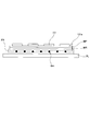
- FIG. 7 is a view showing a cross section when the shoulder support portion of the seat back is cut in a horizontal plane
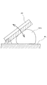
- FIG. 7 is a cross section when the shoulder support portion is cut in a vertical plane
- FIG. It is a figure which shows the structure of the vehicle seat which concerns on a 1st modification. It is a figure which shows the structure of the vehicle seat which concerns on a 2nd modification. It is a figure showing composition of a vehicular seat concerning an application example. It is explanatory drawing about the mechanism which supports the knee lower part of a seated person's leg (the 1). It is explanatory drawing about the mechanism which supports the knee lower part of a seated person's leg (the 2). It is explanatory drawing about the bending state of a seated person's frame
- FIG. 1 It is a schematic diagram which shows the DD cross section in FIG. It is a figure which shows the attachment state of the sensor for attitude
- the “front-rear direction” corresponds to the front-rear direction of the vehicle seat, and corresponds to the direction in which the vehicle travels.
- the “width direction” corresponds to the width direction of the vehicle seat, and specifically, is the left-right direction when the vehicle seat is viewed from the front.
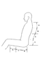
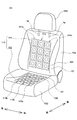
- FIG. 1 is a view showing a schematic configuration of the present sheet S. As shown in FIG.
- the present seat S is common to a conventional vehicle seat in its basic configuration (configuration except for a shoulder support portion described later). That is, as shown in FIG. 1, the main seat S includes a seat back S1 supporting the seated person from the back side, a seat cushion S2 supporting the buttocks of the seated person, and a headrest S3 supporting the head of the seated person ing.
- the seat back S1 and the seat cushion S2 are configured by placing a pad material on the frame body and then covering the pad material with a skin material.
- the headrest S3 is configured by arranging a pad material on the core material of the head and then covering the core material with a skin material.
- the headrest S3 is supported by the upper end portion of the seatback S1 via a headrest pillar hp.
- the present sheet S is characterized in a shoulder support portion Sa1 which is a portion for supporting a seated person's shoulder in the seat back S1.
- the shoulder supporting portion Sa1 wraps the shoulders of the seated person and presses the shoulder.
- the mechanism mounted in the shoulder support Sa1 operates to cause the shoulder support Sa1 to abut the shoulder of the seat occupant.
- the force indicated by symbol F in FIG. 1 acts from the shoulder support Sa1 toward the shoulder of the seat occupant.
- the force F has a component directed inward in the width direction and a component directed downward, as shown in the figure. Therefore, the shoulders of the seat occupant are pushed inward in the width direction and also downward.
- the upper body of the seat occupant is displaced in the width direction and the vertical direction by being supported by the shoulder support portion Sa1 of the seat back S1 and pushed inward and downward in the width direction. It is possible to suppress Thus, the posture of the seated person can be stably held while seated on the main seat S.
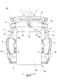
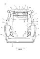
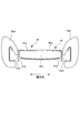
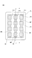
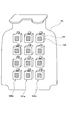
- FIG. 2 is a view showing the configuration of the seat back frame Sf1 of the seat back S1 of the main sheet S, and is a view of the seat back frame Sf1 as viewed from the front.
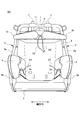
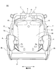
- FIG. 3 illustrates a state in which the plate-like member is removed from the seat back frame Sf1 illustrated in FIG.
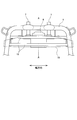
- FIG. 4 illustrates a state in which the support plate is removed from the upper end portion of the seat back frame Sf1 as an explanatory view of the attachment position of the support plate, and the attachment position of the support plate is indicated by a broken line in FIG. ing.
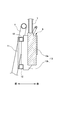
- FIG. 5 is a view showing an AA cross section in FIG. Note that for convenience of illustration, each component described in FIGS. 2 to 5 is somewhat simplified. For example, in FIG. 5, the internal structure of the pillar position adjusting mechanism 6 is omitted. ing.
- a seat back frame Sf1 is provided inside the seat back S1, and various parts constituting the seat back S1 are attached to the frame Sf1.
- the seat back frame Sf1 forms a framework of the seat back S1 and is a substantially rectangular frame in a front view. Specifically, the seat back frame Sf1 connects the upper frame 1 disposed at the upper end, the pair of side frames 2 provided respectively at both ends in the width direction, and the lower ends of the side frames 2 And a lower connecting frame 3.
- the upper frame 1 is an inverted U-shaped portion, and is formed by bending a metal pipe into a substantially U-shape. One end of the upper frame 1 is connected to the upper end of one side frame 2, and the other end is connected to the upper end of the other side frame 2. That is, the upper frame 1 connects the upper ends of the pair of side frames 2 with each other.
- a headrest S3 is disposed above the upper frame 1. More specifically, a pillar position adjusting mechanism 6 provided with a pillar support portion 7 for supporting a headrest pillar hp extending from the lower portion of the headrest S3 is provided at the rear of the upper frame 1.
- the pillar position adjustment mechanism 6 is a mechanism that automatically adjusts the height of the headrest S3 by moving the position of the headrest pillar hp supported by the pillar support 7 in the vertical direction by a drive mechanism (not shown).
- a square pipe-shaped holding pipe 12 extending from one end to the other end of the upper frame 1 is attached to the upper frame 1.
- two holding pipes 12 are arranged in the vertical direction, but the number of holding pipes 12 can be set arbitrarily.
- a mounting bracket 13 for mounting the pillar position adjusting mechanism 6 is fixed to the holding pipe 12. More specifically, the mounting bracket 13 includes a base 13a to which the pillar position adjusting mechanism 6 is attached, and a pair of side portions 13b extending forward from both side ends of the base 13a. The mounting bracket 13 is fixed to the holding pipe 12 by welding the tips of the side portions 13 b to the rear surfaces of the two holding pipes 12.
- the pair of side frames 2 is a portion that configures the side surface of the seat back frame Sf1, and is disposed to be separated in the left-right direction to define the width of the seat back S1, and extends in the up-down direction.
- the configuration of each side frame 2 will be described. As shown in FIGS. 2 and 3, each of the flat side plate 2a and the front edge 2b bent inward in a U-shape from the front end of the side plate 2a The side frame 2 is provided.
- air cells (hereinafter, side air cells 4) are attached to the surface located on the inner side in the width direction, and the side air cells 4 constitute a side support Sa2.
- the side support Sa2 corresponds to a movement restricting portion, and air, which is an example of a fluid, is enclosed in the side air cell 4 and bulging inward in the width direction to restrict movement of the upper body of the seated person in the width direction.
- the side supports Sa2 are provided at both ends in the width direction of the seat back S1, and are disposed at substantially the same height as the abdomen of the seated person in the vertical direction.
- a tube member C1 for air supply and exhaust is connected to the side air cell 4 constituting the side support Sa2.
- a pressure receiving plate 5 is disposed which receives pressure when the back of the seated person leans on the seat back S1.
- the pressure receiving plate 5 is a member made of resin and is formed in a substantially T shape in a front view. Further, the wider upper end portion of the pressure receiving plate 5 is bent such that both widthwise end portions thereof are slightly forward.
- the pressure receiving plate 5 is attached to each side frame 2 by a bonding wire 5a having elasticity. More specifically, the bonding wire 5 a is stretched between the pair of side frames 2, and both ends thereof are locked to the side frames 2. The central portion of the bonding wire 5 a is hooked to a hook (not shown) formed on the back surface of the pressure receiving plate 5. As a result, the pressure receiving plate 5 is disposed in the space provided between the pair of side frames 2.
- the coupling wire 5a having elasticity is bent and the pressure receiving plate 5 is moved rearward.
- the upper body of the seated person sinks appropriately toward the rear.
- the shape of the pressure receiving plate 5 it is not limited to what was described in FIG. 3 etc., You may be another shape.
- the feature of seat back S1 concerning this embodiment is a point provided with shoulder support part Sa1 which supports so that a passenger's shoulder may be wrapped.
- the internal structure of the shoulder support portion Sa1 according to this embodiment includes the air cell 10 shown in FIG. 3 and the resin plate 20 shown in FIG.
- the air cell 10 is a bag which is expanded by enclosing air, which is an example of a fluid, inside, and two air cells are arranged in the width direction as shown in FIG. 2. If it demonstrates concretely, the external shape of each air cell 10 is a rectangular shape by which one end side became a semicircle by the plain view. However, the outer shape of the air cell 10 is not particularly limited, as long as the shape is elongated in a predetermined direction. Further, in the present embodiment, the air cell 10 that expands by being filled with air is used as an example of the bag, but a bag that is expanded by being filled with a fluid other than air, for example, a liquid It is also possible to use
- the two air cells 10 are positioned immediately above the pressure receiving plate 5 in the vertical direction, and the longitudinal direction of the two air cells 10 is slightly inclined with respect to the width direction.
- the end on the outer side in the width direction is outside the side end of the seat back frame Sf1 (strictly, the side end of the upper frame 1) as shown in FIG. It is in the position where it slightly protruded.
- each air cell 10 is provided such that an end on the outer side in the width direction among the both ends in the longitudinal direction is positioned lower than an end on the inner side in the width direction. Furthermore, although a gap is formed between the two air cells 10 in the width direction, such a gap is located at the widthwise central portion of the seat back S1, as shown in FIG.
- support plate 11 is attached to seat back frame Sf1.
- the support plate 11 is a metal plate elongated in the width direction, and supports each of the two air cells 10 from the rear. Further, both side ends of the support plate 11 reach the side end of the seat back frame Sf1 and are further bent backward.
- Each of the two air cells 10 is supported by being attached to the front surface of the support plate 11. Specifically, the longitudinal center of each air cell 10 is fastened to the support plate 11. Further, among the both end portions in the longitudinal direction of each air cell 10, a tongue-like protrusion (not shown) is provided at the end on the outer side in the width direction, and this tongue-like protrusion is along the side edge of the support plate 11. It is bent backward and screwed to the side end.
- the support plate 11 is attached to the front surface of the seat back frame Sf1 so as to be positioned at substantially the same height as the junction between the upper frame 1 and the side frame 2 in the vertical direction.
- the mounting position of the support plate 11 will be specifically described with reference to FIGS. 4 and 5.
- the support plate 11 has two holding pipes 12 provided to hold the pillar position adjusting mechanism 6 on its rear surface. It abuts on the front face of the pipe and is fixed to each holding pipe 12 by welding. That is, in the present embodiment, the holding pipe 12 functions as a holding portion that holds the support plate 11 in contact with the rear surface of the support plate 11.
- the support plate 11 is held by the holding pipe 12 at the rear thereof, so that the support plate 11 can be properly held without interference with the air cell 10. As a result, each air cell 10 supported by the support plate 11 continues to be well positioned at the predetermined attachment position.
- the support plate 11 is held by the holding pipe 12 provided to hold the pillar position adjusting mechanism 6. That is, in this embodiment, since the member for holding the pillar position adjusting mechanism 6 is also used as the member for holding the support plate 11, it is possible to efficiently improve the support rigidity of the support plate 11.
- a tube member C2 is connected to each air cell 10 as shown in FIG.
- the tube member C2 forms a path of the air supplied to the air cell 10 and the air discharged from the air cell 10, has flexibility, and is provided separately for the air cell 10.
- Each tube member C2 passes through the rear of the pressure receiving plate 5 to the upper end of the pressure receiving plate 5, and further extends from the upper side of the pressure receiving plate 5 to the front side and is connected to each air cell 10.
- each tube member C2 is wired so as to pass through the central portion of the seat back S1 in which the gap formed between the two air cells 10 in the width direction is located.
- the tube member C2 provided separately for the air cell 10 extends from a compressed air supply source (specifically, a compressor 52 described later), passes through the rear of the pressure receiving plate 5, and moves toward the air cell 10. There is.
- a compressed air supply source specifically, a compressor 52 described later
- Each tube member C2 extends from the side of the seat back frame Sf1 toward the center in the width direction of the pressure receiving plate 5 when passing through the rear of the pressure receiving plate 5, and is attached to the rear surface of the pressure receiving plate 5 at the middle position It is bundled by the clip (not shown).
- a portion of each tube member C2 from reaching the widthwise center of the pressure receiving plate 5 to being connected to the air cell 10 extends so as to pass through the widthwise central portion of the seatback frame Sf1.
- the tube members C2 are arranged so as to pass through the widthwise central portion of the seat back S1 in which the gap between the air cells 10 is positioned.
- the seat back S1 in which the gap between the air cells 10 is positioned.
- the resin plate 20 is a plate-like member disposed at the front position of the two air cells 10.
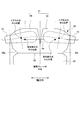
- the resin plate 20 is provided to expand the action range of the force acting on the shoulders of the seated person as the air cell 10 bulges, and has an outer shape elongated in the vertical direction in front view. More specifically, as shown in FIG. 2, the resin plate 20 is located below the deformation portion 21 which deforms as the air cell 10 is bulging, and extends downward. And an extending portion 22. Further, the deformation portion 21 and the extension portion 22 are adjacent to each other, and a groove 23 linearly formed along the width direction is provided at the boundary position. Further, in the width direction both end portions of the region in which the groove 23 is formed in the resin plate 20, a substantially triangular shaped cut 20a is formed inward in the width direction.
- the deformation portion 21 is disposed at the upper end portion of the resin plate 20, and has a substantially hexagonal shape in a front view.
- An inverted triangular notch 24 is formed downward from the upper end at the center in the width direction of the deformation portion 21, and the tip of the notch 24 is slightly lower than the vertical center position of the deformation portion 21. It is located in The deformation portion 21 is separated into two parts (specifically, the one end side deformation piece 25 and the other end side deformation piece 26) with the notch 24 as a boundary, and the separated two parts The one end side deformation piece 25 and the other end side deformation piece 26 can be individually deformed.
- the notch 24 is formed between the two deformation pieces 25, 26 and corresponds to a separation part for separating the two deformation parts 25, 26.
- the one end side deforming piece 25 and the other end side deforming piece 26 are positioned behind the seat occupant's shoulder when the seat occupant's back leans on the seat back S1. More precisely, the one end side deformation piece 25 corresponds to a first portion located behind the one shoulder of the seated person, and the other end side deformation piece 26 is located behind the other shoulder of the seated person It corresponds to the second part located.
- each of the one end side deformation piece 25 and the other end side deformation piece 26 is positioned immediately in front of the corresponding air cell 10 so as to wrap the seater's shoulder when the corresponding air cell 10 is expanded. It deforms while curving. As a result, the shoulder support portion Sa1 of the seat back S1 holds the seated person's shoulders, thereby making it possible to stably hold the seated person's posture.
- the air cell 10 abuts on the rear surface of the corresponding deformation piece 25, 26 and bulges out in this state. And, by the air cell 10 bulging out, a force acts from the air cell 10 on the shoulder of the seated person. At this time, since the action range of the force is expanded by the deformation portion 21, the seat occupant's shoulder is pushed in a wide range.
- the area of the front surface of each deformation piece 25, 26 of the deformation portion 21 is larger than the area of the contact surface of the air cell 10 with the deformation piece 25, 26. For this reason, the force generated by the expansion of the air cell 10 is spread over a wider range on the seat occupant's shoulder.
- the action range of the force generated by the expansion of the air cell 10 is expanded by the resin plate 20, the shoulder of the seated person can be appropriately held down even when the relatively small air cell 10 is used. It becomes.
- the deformation portion 21 is wider than the other portion (specifically, the extension portion 22), and the action range of the force generated by the expansion of the air cell 10 is It is easier to expand.
- the central portion in the vertical direction is the widest, and as shown in FIG. 2, the central portion is located immediately in front of the air cell 10. Further, among the longitudinal ends of each air cell 10, the end that is on the outer side in the width direction is at a position slightly protruding to the outer side than the corresponding deformed piece 25 or 26, as shown in FIG. Furthermore, among the outer edges of the deformation pieces 25 and 26, a portion located at the outer end in the width direction forms a substantially arc-shaped curve to simulate the shoulder of the seater and descends toward the outer side in the width direction So it is inclined.
- the extending portion 22 is a portion ranging from the vertical direction central portion to the lower end portion of the resin plate 20.
- the extension portion 22 (strictly, the lower end portion of the extension portion 22) is located behind the waist of the seated person when the back of the seated person leans on the seat back S1.
- the deformation portion 21 and the extension portion 22 are connected and integrated, and specifically, they are integrally molded articles.
- the extending portion 22 is slightly curved in the vertical direction to form an arc. For this reason, when pushing the waist of the seated person forward by the extension part 22, it becomes possible to suitably push the seated person's waist with a relatively gentle surface.
- the extension 22 is narrower than the deformation 21, and the gap between the pair of side supports Sa2 provided at both ends in the width direction of the seatback S1 (more strictly Is narrower than the side air cells 4). Moreover, when installing the resin plate 20, the extension part 22 is arrange
- Each air cell 10 is located behind the deformed portion 21 of the resin plate 20. More precisely, each air cell 10 is located behind the corresponding deformation piece 25, 26. Specifically, one air cell 10 is located immediately behind the deformation piece 25 at one end, and the other air cell 10 is located immediately behind the deformation piece 26 at the other end. Then, each air cell 10 bulges while in contact with the rear surface of the corresponding deformation piece 25, 26. As a result, the deformation pieces 25 and 26 are deformed, and the shoulder support portion Sa1 in the seat back S1 is pressed so as to wrap the seat occupant's shoulder.
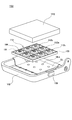
- FIG. 6 is a view showing the positional relationship between the air cell 10 and the resin plate 20. In the drawing, only the air cell 10 and the resin plate 20 are shown in order to make the description easy to understand.
- the positional relationship between the one end side deformation piece 25 and the air cell 10 is obtained by horizontally reversing the positional relationship between the other end side deformation piece 26 and the air cell 10, so in the following description, the one end side deformation portion Only the positional relationship between the piece 25 and the air cell 10 will be described.
- the air cell 10 is located above the center position of the deformation piece 25 on the one end side and outside in the width direction.
- the central position of the air cell 10 is the position of the longitudinal center of the air cell 10 and the central position of the air cell 10 in the height direction.
- the central position of the one end side deformation piece 25 is the position in the width direction center of the one end side deformation piece 25 and the position of the one end side deformation portion 25 in the vertical direction.
- One end in the width direction of the one end side deformation piece 25 corresponds to a portion located on the outermost side in the width direction among the one end side deformation piece 25, and the other width direction end of the one end side deformation piece 25 is described above This corresponds to the tip position of the notch 24 (in other words, the center position in the width direction of the deformation portion 21).
- the tube member C2 for air supply and exhaustion mentioned above is connected by the location substantially corresponding with the center position of the air cell 10 by front view. Therefore, the air cell 10 starts to expand preferentially from its center position. For this reason, when the air cell 10 bulges, a portion of the one-end deformation piece 25 located on the outer side in the width direction is selectively deformed. That is, the one end side deformation piece 25 is deformed so that the part located in the width direction outer side in the one is located ahead of the part located in the width direction inner side.
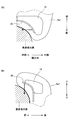
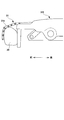
- FIG. 7A is a view showing a state in which the shoulder support portion Sa1 of the seat back S1 supports the shoulder of the seated person, and shows a cross section when the shoulder support portion Sa1 is cut in a horizontal plane.
- FIG. 7A is a view showing a state in which the shoulder support portion Sa1 of the seat back S1 supports the shoulder of the seated person, and shows a cross section when the shoulder support portion Sa1 is cut in a horizontal plane.
- the portion of the one end side deformation piece 25 located on the outer side in the width direction corresponds to the portion corresponding to the one end portion on the outer side in the width direction in the shoulder support portion Sa1.
- the corresponding portion corresponds to a portion corresponding to the one end in the width direction in the shoulder support portion Sa1.
- the portion located on the outer side in the width direction in the deformation piece 25 on one end side is selectively deformed, but in particular, the upper region of the portion is more than the lower region. It also deforms to be positioned forward. This is because the center position of the air cell 10 having the air supply / discharge port is located above the center position of the deformation piece 25 on one end side.
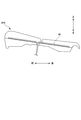
- FIG. 7B is a view showing a state in which the shoulder support portion Sa1 of the seat back S1 supports the seated person's shoulder, and a cross section of the shoulder support portion Sa1 taken along a vertical plane is shown.
- FIG. 7B is a view showing a state in which the shoulder support portion Sa1 of the seat back S1 supports the seated person's shoulder, and a cross section of the shoulder support portion Sa1 taken along a vertical plane is shown.
- the arrangement of the air cell 10 is suitably set for the purpose of promoting selective deformation of the widthwise outer portion of the one-end-side deformation piece 25 when the air cell 10 is expanded.
- each of the air cells 10 is disposed such that one end on the outer side in the width direction of the both ends in the longitudinal direction is located lower than the end on the inner side in the width direction.
- This is a content supposing the shoulder of a general seating person, and the air cell 10 is arranged to be lowered toward the width direction outward like the seating person's shoulder, so that the shoulder support portion of the seat back S1 Sa1 will be supported so as to wrap the seater's shoulders.
- the posture of the seated person sitting on the main seat S is further stabilized.
- the end on the outside in the width direction in the air cell 10 protrudes somewhat outside the end on the outside in the width direction on the one end side deformation piece 25 .
- the widthwise outer portion of the one end side deformation piece 25 is more easily deformed, so it is easy to stabilize the posture of the seated person.
- most of the air cell 10 is located between the upper end position of the deformation piece 25 on one end side and the central position in the vertical direction when viewed from the front. .
- the upper area thereof is easily deformed so as to be positioned forward of the lower area. It becomes easier to stabilize the posture.
- the shape of the resin plate 20 is set to a suitable shape for the purpose of promoting the shoulder support portion Sa1 of the seat back S1 to wrap and support the seated person's shoulder.
- the portion positioned at the end in the width direction outer side has a width simulating the seater's shoulders It is inclined to descend as it goes outward in the direction.
- the portion of the resin plate 20 positioned behind the seated person's shoulder has a shape that simulates the seated person's shoulder, and thus the shoulder support portion Sa1 supports the seated person's shoulder so as to wrap around the seated person's shoulder. The effect is more effective. As a result, the posture of the seated person sitting on the main seat S is further stabilized.
- FIGS. 8 and 9 are views showing the configuration of a vehicle seat according to a modification, and each view illustrates a seat back frame Sf1 having a configuration for holding the air cell 10 different from that of the above embodiment.
- a rod-like member 14 made of a metal member having relatively high rigidity is used instead of providing the holding pipe 12 described above.
- the rod-like members 14 extend downward from the horizontal portion of the upper frame 1 and are provided in pairs at left and right intervals.
- the upper end portion of each rod-like member 14 is fixed to the upper frame 1, and the lower end portion is fixed to a locking portion (not shown) provided on the rear surface of the pressure receiving plate 5.
- an elastic wire 15 is stretched along the width direction.
- a plurality of the wires 15 are arranged in the vertical direction at a constant pitch.
- support plate 11 is attached to the front of these a plurality of wires 15, and, specifically, is attached in the attachment position shown with a dashed line in FIG.
- a deformed pressure receiving plate 16 is provided instead of providing the support plate 11 and the holding pipe 12.
- the pressure receiving plate 16 is somewhat expanded above the pressure receiving plate 5 used in the above-described embodiment. Further, in a state in which the pressure receiving plate 16 according to the modification is attached to the seat back frame Sf1, the upper end thereof is positioned slightly above the arrangement position of the air cell 10.
- the air cell 10 is attached to the upper end portion of the pressure receiving plate 16 according to the modification instead of the support plate 11. Specifically, in FIG. It is attached to the attachment position shown by. With such a configuration, the number of parts is reduced because the support plate 11 is not used, and the work of assembling the seat back frame Sf1 is further simplified.
- FIG. 10 is a diagram showing a basic configuration of the application sheet XS.
- the application seat XS follows the configuration of the vehicle seat (that is, the main seat S) according to the above-described embodiment, and specifically described, the shoulder support corresponding to the shoulder support portion Sa1 in the seat back XS1 Xa1 is provided.
- the shoulder support Xa1 incorporates the air cell 10 and has a function of pushing the seat occupant's shoulder inward in the width direction and downward by the expansion of the air cell 10.
- the application sheet XS includes side supports Xa2 at both ends in the width direction of the seat back XS1.
- the side support Xa2 has the same configuration as the side support Sa2 provided in the vehicle seat according to the above-described embodiment. That is, the side support Xa2 provided in the application sheet XS incorporates an air cell (side air cell 4), and pushes the upper body of the seated person inward in the width direction by the expansion of the side air cell 4.
- the application sheet XS has the site
- a lumbar support Xa3 is provided in a portion of the seat back XS1 that abuts on the seat occupant's waist.
- the lumbar support Xa 3 incorporates a waist air cell 8 and pushes the seat occupant's waist forward by the expansion of the waist air cell 8.
- cushion side supports Xa4 are provided at both widthwise end portions of the seat cushion XS2 of the application sheet XS.
- the cushion side support Xa4 incorporates a side air cell for cushion (hereinafter, cushion air cell 9), and pushes the thigh of the seated person inward in the width direction by the expansion of the cushion air cell 9.
- an ottoman portion Xa5 as a below-knee support portion for supporting the lower knee of the seated person's leg is provided at the front end of the seat cushion XS2 of the application sheet XS.
- the ottoman portion Xa5 is provided with an air cell (air cell 30 for ottoman) disposed at the front end of the seat cushion XS2, and when the ottoman air cell 30 bulges, it supports the lower knee of the leg of the seated person from below. It will be.
- FIGS. 11 and 12 are explanatory views of the ottoman portion Xa5 supporting the lower knee of the leg of the seated person, and a view of the front end of the cushion frame Xf2 constituting the seat cushion XS2 as viewed from the side.
- the support member 31 is attached to the front end portion of the sheet suction XS2 of the application sheet XS, and is constituted by a plurality of support fragments 31a connected.
- Each support segment 31a is formed of a substantially strip-shaped metal plate long in the width direction. Further, in the support member 31, the support pieces 31a adjacent to each other are connected via a hinge so that one support piece 31a can be rotated relative to the other support piece 31a.
- the support member 31 moves toward the support position (the position of the support member 31 shown in FIG. 12) for supporting the lower knee of the leg of the seated person on the front of each support piece 31a. Move.
- the support member 31 moves toward the standby position (the position of the support member 31 illustrated in FIG. 11) which stands by in a state of hanging downward in front of the seat cushion XS2.
- the flat surface more specifically, the front surface of the support piece 31a is supported when supporting the lower knee of the leg of the seated person by the expansion of the air cell 30 for ottoman It is possible to As a result, it is possible to maintain a stable support of the lower knees of the legs of the seated person.
- the application sheet XS is provided with a plurality of movable parts with a built-in air cell. Then, when the seated person is seated on the application sheet XS, each movable portion operates automatically. As a result, the back and thighs of the seated person's body are pressed, and the seated person's posture is corrected. In other words, by sitting on the application sheet XS, the bending state of the seat occupant's skeleton is actively corrected.
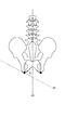
- the bending state of the skeleton is an index related to the three-dimensional structure of the skeleton, such as the shape of the skeleton, the displacement and distortion of the skeleton, and in the present embodiment, as shown in FIG.
- the curvature of the arc shape formed by the respective regions in which the symbols A to G are attached corresponds to the bending state.
- FIG. 13 is an explanatory view of a bending state of a seated person's skeleton.
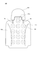
- FIG. 14 is a view showing an example of the arrangement of the attitude measurement sensor in the seat back XS1.
- FIG. 15 is a schematic view showing a cross section taken along a line DD in FIG.
- FIG. 16 is a view showing a mounting state of the posture measurement sensor in the seat cushion XS2, and is a schematic view showing a cross section when the seat cushion XS2 is cut along a vertical plane.
- the shape sensor 40 illustrated in FIG. 14 is used as one of the attitude measurement sensors.
- the shape sensor 40 is made of a shape sensing optical fiber and has flexibility.
- the shape sensor 40 detects the posture of the seated person by bending along the curved shape of the seated person's skeleton. Specifically, when the shape sensor 40 bends in a bow along the back of the body of the seated person seated on the application sheet XS, the refractive index of light at each portion of the shape sensor 40 changes.
- the shape sensor 40 is connected to a circuit board (not shown) via a connector, a cable or the like, and outputs a signal corresponding to the change in the refractive index of light to the circuit board. Then, in the circuit board, a three-dimensional shape such as torsion or bending of the shape sensor 40 is specified based on the output signal from the shape sensor 40, and the posture of the seated person is determined from the specified result.
- the shape sensor 40 is arrange
- a body pressure sensor 41 as another attitude measurement sensor is used together with the shape sensor 40 described above.
- the body pressure sensor 41 has a substantially strip-shaped film shape, and includes a detection unit 41a as a sensor main body, and a transmission path 41b formed to transmit an output signal from the detection unit 41a.
- the detection unit 41a detects the pressure (body pressure) applied when the seated person is seated on the application sheet XS, and outputs a signal according to the magnitude of the body pressure.
- the transmission path 41b is routed from the front to the rear of the seat back XS1.
- the body pressure sensor 41 is disposed at a position avoiding the shape sensor 40 in the width direction, and more specifically, as shown in FIG. It is provided side by side. More specifically, the body pressure sensor 41 is disposed at a position where it can measure the body pressure distribution in the vicinity of the shoulder, the entire back, and the waist of the seated person.
- each body pressure sensor 41 intervenes between pad material XP1 which constitutes seat back XS1, and skin material.
- the pad material XP1 is made of, for example, urethane, and as shown in FIG. 15, has a flat portion Pa1 at the center in the width direction and raised portions Pb1 at both ends in the width direction. Further, between the flat portion Pa1 and the protruding portion Pb1, a hanging groove Pc1 for hanging the skin material is formed along the height direction (vertical direction of the sheet) of the pad material XP1.
- the transmission path 41b of the above-described body pressure sensor 41 is routed from the front to the back of the seat back XS1 as described above, but the wiring path is naturally as short as possible. Is desirable. On the other hand, the wiring path of the transmission path 41b needs to be set to a path that minimizes the discomfort felt by the seated person by providing the transmission path 41b.
- a hole penetrating to the back surface of the pad material XP1 is formed in several places of the hanging groove Pc1, and the transmission path 41b is taken toward the back surface of the pad material XP1 through the hole as shown in FIG. It is supposed to turn.
- the position where the above-mentioned hole is formed in the hanging groove Pc1 is preferably determined in accordance with the installation position of the body pressure sensor 41. For example, at the position adjacent to the body pressure sensor 41 Good to have.
- a capacitance sensor 42 as another posture measurement sensor is used.
- the capacitance sensor 42 is routed toward the lower surface of the seat cushion XS2.
- the pad material XP2 constituting the seat cushion XS2 has a hole communicating with the lower surface, and the capacitance sensor 42 is directed to the lower surface of the seat cushion XS2 through the hole. It is supposed to go around.
- the capacitance sensor 42 is attached to the upper surface of the pad material XP2, but in such attachment method, an excessive load is applied to the capacitance sensor 42 at the time of seating. May damage the sensor.
- an excessive load is applied to the capacitance sensor 42 at the time of seating. May damage the sensor.
- the capacitance sensor 42 is on the upper surface of the pad member XP2, a sense of discomfort may be given to a seated person seated on the seat.
- the installation range of the component is limited by the installation of the capacitance sensor 42.
- the capacitance sensor 42 is embedded in the pad material XP2. More specifically, after the lower portion of the pad material XP2 is formed, the capacitance sensor 42 is attached to the surface (upper surface) of the portion, and then the upper portion of the pad material XP2 is formed. With this configuration, in the application sheet XS, the problem in the case where the capacitance sensor 42 is attached to the upper surface of the pad material XP2 is resolved.
- the upper portion of the pad material XP2 is prepared as a separate component, and after attaching the capacitance sensor 42, the pad material XP2 is formed. It is good to paste the upper part as a separate part on the lower part.
- the lower portion of the pad material XP2 to which the capacitance sensor 42 is attached is re-inserted into a mold (not shown), and the upper portion of the pad material XP2 is molded in a manner of insert molding.
- the material XP2 may be integrally molded.
- the sensor for posture measurement described above is mounted on the application sheet XS, and for example, when the seated person is seated, the measurement of posture by the sensor is automatically started. Further, in the application sheet XS, weight sensors for measuring the weight of the seated person are provided one each in front, rear, left and right. The weight measurement by the weight sensor is performed simultaneously with the posture measurement.
- the application sheet XS can correct the posture of the seated person (in other words, the bending state of the skeleton) by the configuration described above.
- correction control of the seating posture by the application sheet XS will be described in detail.
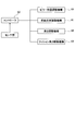
- FIG. 17 is a block diagram showing the configuration of a system that executes correction control of the sitting posture.
- a system (hereinafter, control system CS) that executes correction control of the sitting posture includes the above-described sensor group, the controller 50, a movable portion with a built-in air cell mounted on the application sheet XS, and a movable portion And a drive mechanism for driving the unit.
- the movable portion is the aforementioned shoulder support Xa1, side support Xa2, lumbar support Xa3, cushion side support Xa4, and ottoman portion Xa5.
- the control system CS further includes a pillar position adjustment mechanism 51.
- the pillar position adjusting mechanism 51 is mounted on the application sheet XS, and adjusts the position of the headrest pillar hp in the vertical direction and the front-rear direction. Then, the pillar position adjustment mechanism 51 adjusts the position of the headrest pillar hp, whereby the position of the headrest XS3 fluctuates in the vertical direction and in the front-rear direction.
- the control system CS further includes a tilt mechanism 55.
- the tilt mechanism 55 is mounted on a seat cushion XS2 of the application sheet XS, in particular, at a front end portion of a cushion for supporting a thigh of a seated person, and adjusts a seat surface angle of the front end portion.
- the sensor group includes an attitude measurement sensor, a weight sensor, and the like mounted on the application sheet XS.
- the bending state of the skeleton, the pressure distribution near the shoulders, the pressure distribution at each part of the back, the pressure distribution near the waist, the pressure distribution in the range from the buttocks to the back of the knee, And weight can be measured.
- the controller 50 is an ECU (Electronic) mounted on a vehicle. Control Unit) receives output signals from each sensor and calculates various index values regarding the posture of the seated person. For example, the controller 50 calculates the position of the center of gravity of the seated person from the measurement result of the pressure distribution on the back.
- ECU Electronic
- Control Unit receives output signals from each sensor and calculates various index values regarding the posture of the seated person. For example, the controller 50 calculates the position of the center of gravity of the seated person from the measurement result of the pressure distribution on the back.
- the controller 50 controls the movable portion built in the air cell and the pillar position adjustment mechanism 51 mounted on the application sheet XS based on the calculated value.
- the movable portion built in the air cell operates by the operation of the drive mechanism.
- the drive mechanism is provided in the compressor 52, the air supply passage 53 connected to the compressor 52 (specifically, the passage formed by the above-described tube members C1 and C2), and the air supply passage 53.
- an electromagnetic valve 54 is provided for each air cell, and the end of each air supply passage 53 is connected to each air cell.
- the solenoid valve 54 is also provided for each air cell (that is, for each air supply passage 53).
- the controller 50 controls the amount of expansion of each air cell by controlling the on / off of the compressor 52 and the opening / closing of the solenoid valve 54. Further, the controller 50 controls the pillar position adjustment mechanism 51 such that the headrest pillar hp reaches the target position by turning on and off a drive mechanism (not shown) mounted in the pillar position adjustment mechanism 51. Further, the controller 50 controls the tilt mechanism 55 so that the seating surface angle of the front end portion of the seat cushion XS2 becomes a predetermined angle by turning on and off a drive mechanism (not shown) mounted in the tilt mechanism 55.
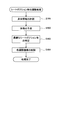
- FIG. 18 is a schematic view showing a flow of correction control of the sitting posture.
- the correction control of the sitting posture proceeds in the order of cushion side control processing S001, waist control processing S002, shoulder control processing S003, and headrest position control processing S004. Each control process will be individually described below.
- cushion side control processing S001 is a control process for optimizing the pressure distribution in the range from the buttocks to the back of the knee (hereinafter, a seat surface pressure distribution optimization process) and a control for moving the position of the center of gravity of the seated person to a normal position. It is divided into processing (hereinafter, gravity center correction processing).
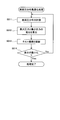
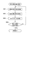
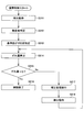
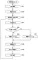
- the seat pressure distribution optimization process will be described according to the procedure shown in FIG. FIG. 19 is a diagram showing the procedure of seat pressure optimization processing.
- the seating pressure distribution optimization process starts from measuring the seating pressure distribution, that is, the pressure distribution in the range from the buttocks to the back of the knee when the seated person is seated on the application sheet XS (S011). After measurement, the controller 50 calculates an index value of the bearing pressure distribution (S012).
- the index value of the bearing pressure distribution is not particularly limited, but the maximum pressure and the minimum pressure in the measured bearing pressure distribution are specified, and the difference between the two pressures is calculated.
- the controller 50 controls the tilt mechanism 55 so that the seating surface angle of the front end portion of the seat cushion XS2 changes by a predetermined amount (S013). Then, in the step S011 of measuring the bearing pressure distribution, the step S012 of calculating the difference between the maximum pressure and the minimum pressure in the bearing pressure distribution, and the step S013 of controlling the tilt mechanism 55, the above difference is at a minimum. To be repeated. Finally, when the above difference is minimized (S014), the bearing pressure distribution optimization process is completed.
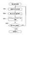
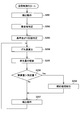
- the gravity center correction process is performed according to the procedure shown in FIG. FIG. 20 is a diagram showing the procedure of the gravity center correction process. Specifically, the center-of-gravity correction process starts from the point where the seating pressure distribution is measured when the seated person is seated on the application sheet XS (S021). After measurement, the controller 50 calculates the bearing pressure balance, in other words, the displacement amount of the center of gravity from the measurement result (S022).
- the procedure for calculating the displacement amount of the center of gravity from the measurement result of the bearing pressure distribution is not particularly limited, but if one example is described, the measured bearing pressure distribution is determined at the central position in the sheet width direction. The boundary is divided into two on the left and right, and the average value of the pressure distribution on the left side and the average value of the pressure distribution on the right side are respectively calculated. Then, the difference between the two calculated average values is calculated as the deviation amount of the center of gravity.
- the controller 50 controls the compressor 52 and the solenoid valve 54 so that the air cells (the cushion air cells 9) of the cushion side support Xa4 expand by a predetermined amount (S023). Then, in the step S021 of measuring the bearing pressure distribution, the step S022 of calculating the displacement amount of the center of gravity, and the step S023 of operating the cushion side support Xa4, in other words, the bearing surface pressure is approximately It is repeated until it becomes symmetrical. Finally, when the shift amount of the center of gravity disappears (S024), the center-of-gravity correction process is completed.
- the waist control process S 002 is a control process for optimizing the body pressure distribution on the back side of the seated person (hereinafter, body pressure distribution optimization process) and a control process for moving the seated person's center of gravity position to a normal position (hereinafter, And second gravity center correction processing).
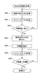
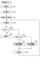
- FIG. 21 is a diagram showing the procedure of the body pressure distribution optimization process.
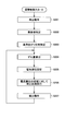
- the body pressure distribution optimization process starts from measuring the body pressure distribution on the dorsal side of the seat occupant when the seat occupant is seated on the application sheet XS (S031). After the measurement, the controller 50 controls the compressor 52 and the solenoid valve 54 so that the air cell (lumbar air cell 8) of the lumbar support Xa3 is expanded by a predetermined amount (S032).
- These steps S031 and S032 that is, measurement of the body pressure distribution on the back side and operation of the lumbar support Xa3) are easy to understand until the operation limit of the lumbar support Xa3 is reached. It is repeated until it becomes maximum (S033).
- an optimum body pressure distribution is determined (S034).
- the procedure for determining the optimal pressure distribution is not particularly limited, but to give an example, the measured pressure distribution on the back is divided into the upper back, the central back, and the lower back. Calculate the average value of body pressure for each part. Then, the difference between the maximum value and the minimum value among the three calculated average values is obtained.
- the body pressure distribution when the difference becomes the smallest is set as the optimum body pressure distribution.
- the controller 50 sets the operation amount of the lumbar support Xa3 when the same measurement result as the optimal body pressure distribution is obtained (S035). Thereafter, the controller 50 controls the compressor 52 and the solenoid valve 54 so that the operation amount of the lumbar support Xa3 reaches the target amount (S036). Finally, when the operation amount of the lumbar support Xa3 reaches the target amount (S037), the body pressure distribution optimization process is completed.
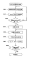
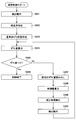
- the body pressure distribution optimization process can be realized by the procedure shown in FIG. 22 in addition to the procedure shown in FIG. FIG. 22 is a diagram showing a modification of the procedure of the body pressure distribution optimization process.
- the body pressure distribution optimization process starts from measuring the body pressure distribution in the pelvic part of the back of the seated person when the seated person is seated on the application sheet XS ( S041).
- the controller 50 controls the compressor 52 and the solenoid valve 54 so that the waist air cell 8 expands by a predetermined amount (S042).
- steps S041 and S042 that is, measurement of body pressure distribution in the pelvic region and actuation of the lumbar support Xa3 are repeated until the body pressure distribution in the pelvic region becomes a target body pressure distribution (S043).
- the target body pressure distribution is an ideal distribution as a body pressure distribution in the pelvic region, and specifically, it is clarified by statistical data and experiments.
- the weight of the seated person is measured (S044), and the controller 50 further calculates the target pressure from the measurement result of the weight (S045).
- the target pressure is an ideal body pressure at a predetermined site (specifically, a site anatomically referred to as “T9”) of the seat occupant's spine.
- the procedure for calculating the target pressure from the weight is not particularly limited, but if one example is described, the correlation between the ideal pressure and the weight at a predetermined site of the seated person's spine is experimentally clarified And calculate the target pressure from the correlation equation.
- the body pressure at a predetermined site (specifically, a site corresponding to "T9") of the spine of the seated person is measured (S046).
- the controller 50 controls the compressor 52 and the solenoid valve 54 so that the waist air cell 8 expands by a predetermined amount (S047).
- the second gravity center correction process is performed according to the procedure shown in FIG. FIG. 23 is a diagram showing the procedure of the second gravity center correction process.
- the second center-of-gravity correction process starts from the measurement of the pressure distribution on the back side of the seated person at the time when the seated person is seated on the application sheet XS (S051).
- the controller 50 calculates the degree of distortion of the spine (the degree of bending in the lateral direction) from the measurement result (S052).
- the procedure for calculating the degree of distortion of the spine from the pressure distribution on the dorsal side is not particularly limited, but if one example is described, the position where the spine is located at the lowest pressure point in the pressure distribution. It corresponds to Therefore, in the normal sitting posture, as shown in FIG. 24, the location with the lowest body pressure in the body pressure distribution is located at the center in the width direction of the seat, and in such a state, the center of gravity is normal. Exist in position.
- FIG. 24 is a diagram showing the relationship between the back pressure distribution and the barycentric position.
- the controller 50 controls the compressor 52 and the solenoid valve 54 so that the air cells (side air cells 4) of the side support Xa2 expand by a predetermined amount (S053). Then, the step S051 of measuring the back pressure distribution, the step S052 of calculating the degree of distortion of the spine, and the step S053 of activating the side support Xa2 are performed until the center of gravity reaches the normal position. Repeat until the distortion disappears. Finally, when the center-of-gravity position reaches the normal position (S054), the second center-of-gravity correction process is completed.
- the shoulder control process S003 is a process for supporting the seated person's shoulder appropriately according to the corrected sitting posture, and is executed in the procedure shown in FIG.
- FIG. 25 is a diagram showing the procedure of the shoulder control process S003.
- the shoulder control process S003 starts from the measurement of the physical pressure distribution in the vicinity of the shoulder of the seated person when the seated person is seated on the application sheet XS (S061). After measurement, the controller 50 calculates an index value related to the body pressure distribution in the vicinity of the shoulder from the measurement result (S062).
- the index value related to the body pressure distribution in the vicinity of the shoulder is not particularly limited, but if one example is described, an average value in the measured body pressure distribution is calculated.
- the controller 50 controls the compressor 52 and the solenoid valve 54 so that the air cell 10 expands by a predetermined amount so as to operate the shoulder support Xa1 (S063).
- the shoulder support Xa1 pushes the shoulder of the seat occupant so that a force directed inward and downward to the shoulder of the seat occupant is applied.
- the above-described steps namely, the step S061 of measuring the body pressure distribution near the shoulder, the step S062 of calculating the average value of the body pressure distribution, and the step S063 of operating the shoulder support Xa1 are the above average values. Are repeated until the target value is reached.
- the target value is an average value in the body pressure distribution in the vicinity of the shoulder in a state where the shoulder is well held, and is clarified by statistical data, an experiment, or the like.
- the shoulder control process S003 is completed.
- the contact pressure applied to the shoulder of the seat occupant by the shoulder support Xa1 is appropriately adjusted, and the shoulder of the seat occupant is supported and supported by the shoulder support Xa1.
- the headrest position control process S 004 is a process for appropriately supporting the head of the seated person in accordance with the corrected seating posture.
- the controller 50 controls the pillar position adjustment mechanism 51 based on the body pressure distribution of each part changed by the posture correction.
- the positions of the headrest pillar hp and the headrest XS 3 supported by the headrest pillar hp are adjusted to appropriate positions according to the corrected sitting posture.
- the procedure of the headrest position control process S 004 that is, the adjustment procedure of the position of the headrest pillar hp is not particularly mentioned, the procedure is freely performed as long as it is adjusted to a position where the head of the seated person can be suitably supported. It is possible to determine
- the correction control of the sitting posture proceeds, and when all the series of control processes are completed, the posture of the seated person is corrected to a suitable posture.
- the correction control proceeds in the order of the cushion side control processing S001, the waist control processing S002, the shoulder control processing S003, and the headrest position control processing S004, but the present invention is not limited to this. . That is, the order of each control process in the correction control can be considered other than the above example.
- the correction control may proceed in the order shown in the following R1) to R9).
- each control process is represented by a code only, and for example, the cushion side control process S001 is described as S001.
- the application sheet XS of the configuration developed as described above can actively adjust its position and state.
- the application sheet XS according to the development includes the above-described sensor group, the controller 50, and the pillar position adjusting mechanism 51, and further, the longitudinal position adjusting mechanism 61 and the height.
- An adjustment mechanism 62 and a cushion length adjustment mechanism 63 are provided.
- FIG. 26 is a diagram showing a development configuration of the application sheet XS, and strictly speaking, shows a configuration of a system for adjusting the sheet position and the state of the sheet.
- the front and back position adjustment mechanism 61 is a mechanism for moving the application sheet XS back and forth, and comprises a known slide rail device provided in the lower part of the seat and a drive mechanism for driving a movable portion of the slide rail device.
- the height adjustment mechanism 62 is a mechanism for adjusting the position of the application sheet XS in the vertical direction, and includes a known pivoting link device provided in the lower part of the seat and a drive mechanism for driving the pivoting link.
- the cushion length adjustment mechanism 63 is a mechanism for extending the entire length (length in the front-rear direction) of the seat cushion XS2 of the application sheet XS.
- the cushion length adjusting mechanism 63 drives an expansion device (for example, a device corresponding to the above-mentioned ottoman portion Xa5) provided in a movable state at the front end of the seat cushion XS2 and a movable portion of the expansion device. Drive mechanism.
- an expansion device for example, a device corresponding to the above-mentioned ottoman portion Xa5
- the controller 50 predicts the physique of the seated person from the measurement results when the physical information of the seated person is measured by various sensors. Thereafter, the controller 50 controls each of the above-mentioned mechanisms (specifically, the pillar position adjusting mechanism 51, the longitudinal position adjusting mechanism 61, the height adjusting mechanism 62, and the cushion length adjusting mechanism 63) based on the prediction result. As a result, the position, the cushion length and the headrest position (hereinafter referred to as the seat position and the like) of the application sheet XS according to the development example are adjusted to the optimum contents in accordance with the predicted physical size of the seated person.
- the controller 50 controls each of the above-mentioned mechanisms (specifically, the pillar position adjusting mechanism 51, the longitudinal position adjusting mechanism 61, the height adjusting mechanism 62, and the cushion length adjusting mechanism 63) based on the prediction result.
- FIG. 27 is a diagram showing a procedure regarding adjustment processing of a seat position and the like.
- Adjustment processing of a seat position etc. starts from the place which measures a seated person's physical information by various sensors mounted on application sheet XS (S101).
- S101 the weight of the seated person is measured by the weight sensor mounted on the application sheet XS, and the body width of the seated person (the lateral width of the trunk) is measured.
- the measurement of the body width is not particularly limited.
- the body pressure distribution of the seated person (especially the pressure distribution near the lumbar spine or pelvis) is measured, and then the seated person and the seat are measured. It is conceivable to determine the contact length with the body and to determine the body width from the contact length.
- the seat occupant may be imaged by a camera installed in front of the seat, and the image may be analyzed to determine the body width.
- the measurement step S101 is automatically performed when a predetermined condition is satisfied.
- any of the following 1) to 4) can be adopted as the execution condition of the measurement step S101.
- the seating surface temperature of the seat cushion XS2 is monitored by a temperature sensor, and it is detected that the heating rate of the seating surface temperature is above the threshold value
- the measurement step S101 may be performed when a seated person operates a switch (not shown) provided in the vehicle, in addition to the cases listed in the above 4) to 4).
- the controller 50 predicts the physical constitution of the seated person from the measurement result (S102). Specifically, the controller 50 predicts the height of the seat occupant from the measured body width and weight, and further predicts the physique of the seat occupant from the predicted height.
- the physique of the seated person corresponds to the length of the seated person's leg, the length of the arm, the position of the head, the height of the eyes and the like.
- the method of predicting height from body width and weight, and the method of predicting the physical constitution of a seated person from height are not particularly limited. It is good also as calculating
- the controller 50 specifies an optimal seat position or the like according to the physique based on the predicted physique of the seating person (S103). Specifically, the controller 50 predicts the length of the leg of the seat occupant, the length of the arm, the position of the head, and the height of the eyes in the previous step S102, and the adjustment items corresponding to these parameters , Determine the adjustment amount.
- the correspondence relationship between various parameters and adjustment items is as shown in FIG. 28. For example, the seat position and the cushion length in the front-rear direction are adjusted according to the length of the leg.
- FIG. 28 is a diagram showing the correspondence between each parameter related to the physical constitution of the seated person and the adjustment items related to the seat.
- the controller 50 controls the pillar position adjusting mechanism 51, the longitudinal position adjusting mechanism 61, the height adjusting mechanism 62, and the cushion length adjusting mechanism 63 according to the specified result after specifying the optimum seat position etc. (S104) .
- the sheet position or the like of the application sheet XS is adjusted to the optimum content specified in the previous step S103.
- the adjustment process of the sheet position and the like is completed.
- the adjustment amount regarding the seat position etc. is determined according to the parameter related to the physical constitution of the seated person, and the parameter is predicted based on the body width and weight of the seated person measured in the measurement step S101. It is supposed to be Therefore, the adjustment amount for the seat position etc. depends on the prediction result on the physical size of the seat occupant, and if the prediction result differs from the true physical shape, an error is generated in the calculation result of the adjustment amount. There is a possibility that the seat position etc. may not be optimized.
- E1 to E6 are listed as factors causing the above-mentioned error.
- E1 The weight can not be accurately measured because the foot of the seated person sitting on the application sheet XS is on the vehicle floor
- E2) The weight can not be accurately measured by the clothes worn by the seated person
- E3) sitting
- the body width is not measured accurately by the clothes worn by the person
- E5) The relationship between body width, weight and height of the seated person deviates from the relationship shown in the formula for predicting height from body width and weight (correlation equation)
- E5 The relationship between the height of the seat occupant and the physical constitution deviates from the relationship shown in the equation (correlation equation) for predicting the physical constitution from the height
- the seating condition of the occupant of the seat is normal Be different from
- the application sheet XS is used for weight measurement in contrast to the fact that the weight can not be accurately measured because the foot of the seated person is on the vehicle floor as the first error factor E1.
- the height adjustment mechanism 62 raises the height of the sheet to the highest position in the adjustment range.
- the foot of the seated person floats up from the vehicle body floor and the entire weight is applied to the application sheet XS, so that it is possible to accurately measure the weight.
- a method of eliminating the above error requirement E1 is considered other than the above contents.
- the cushion length adjustment mechanism 63 maximizes the cushion length and the entire leg is placed on the seat cushion XS2, Similar to the above-described content, the entire application sheet XS is heavy.
- a correction formula for correcting the measurement result is determined, and the measurement result is corrected by the correction formula. You may do it.
- weight measurement is continued from the time when the door of the vehicle is opened, and taking advantage of the fact that the seater's foot leaves the vehicle floor at the moment of sitting on the seat, measurement results at that moment (in other words, application sheet XS
- the total weight may be taken as the net weight.
- the capacitance sensor 42 mounted in the seat cushion XS2 is applied to the application sheet XS according to the development example as opposed to “the weight is not accurately measured by clothes” mentioned as the second error factor E2.
- the weight measurement result is to be corrected based on the measurement result of More specifically, the measurement result of the capacitance sensor 42 fluctuates according to the amount of clothes of the seated person, so the correction amount according to the measurement result of the capacitance sensor 42 is calculated, and the correction amount is calculated. It is added to the measurement result of weight and it is considered as net weight.
- the correlation between the measurement result of the capacitance sensor 42 and the correction amount is clarified by experiment etc., and the measurement result of the capacitance sensor 42 is substituted into the correlation formula. It is good to calculate
- the capacitance sensor mounted in the seat cushion XS2 The weight measurement result is to be corrected based on the 42 measurement results. That is, similarly to the correction of the weight described above, the correction amount according to the measurement result of the capacitance sensor 42 is calculated, and the measurement result of the body width is corrected with the correction amount to obtain a net body width.
- the correlation between the measurement result of the capacitance sensor 42 and the correction amount is clarified by experiment etc., and the measurement result of the capacitance sensor 42 is substituted into the correlation formula. It is good to calculate
- the application sheet XS according to the development example will be described with respect to "the relationship between the body width, weight and height of the seated person being out of the correlation formula used for height prediction" mentioned as the fourth error factor E4.
- the seat occupant can re-adjust the seat position and the like by operating a switch (not shown).
- the controller 50 learns the operation amount of the seat occupant, that is, the readjustment amount. Then, in the adjustment after the next time, the adjustment reflecting the operation amount (readjustment amount) is performed.
- the difference amount of the seating condition is It is decided to adjust the seat position etc. in consideration.
- the "seating state” means the seating position and the seating posture of the seated person.
- “a state different from the normal sitting state” means, for example, a state in which the seated person is seated at a position slightly ahead of the normal sitting position, more specifically, the buttocks of the seated person are normal It is located in front of the position, and the seater's back leans backward than usual.
- the controller 50 detects that and calculates the amount of difference from the normal sitting state.
- weight sensors are provided at four front, rear, left, and right locations, and the controller 50 measures the current position of the center of gravity of the seated person based on the measurement results by each weight sensor. calculate.
- the calculation method of a gravity center position it is possible to utilize a well-known calculation method.
- the controller 50 calculates the position between the calculated center of gravity and the normal position of gravity. Calculate the deviation amount of The shift amount of the center of gravity position corresponds to the difference amount of the sitting state.
- the normal center-of-gravity position is obtained from data obtained when the seated person is seated on the application sheet XS in the normal seating state, and is stored in the controller 50 in advance.
- the controller 50 determines each adjustment amount in consideration of the deviation amount of the gravity center position described above.
- a vehicle seat (hereinafter, skeleton correction sheet YS) capable of efficiently correcting the bending state of the seat occupant's skeleton will be described.
- the configuration of the vehicle seat of the present invention that is, the configuration in which the movable shoulder support portion Sa1 is provided on the seat back S1
- Description will be made by focusing attention only on the configuration for efficiently correcting the bending state of. Therefore, also in the explanatory view (specifically, the drawings after FIG. 29) regarding the skeleton correction sheet YS, the illustration is somewhat simplified, except for the device for efficiently correcting the bending state of the seated person's skeleton. Will be omitted.
- FIG. 29 is a view showing the skeleton correction sheet YS
- FIG. 30 is an exploded view of the seat back YS1 in the skeleton correction sheet YS
- FIG. 31 is an exploded view of the seat cushion YS2 in the skeleton correction sheet YS. is there.
- the skeleton correction sheet YS is mounted with the correction device 110 as shown in FIG.
- the correction device 110 presses the back of the seater seated on the skeleton correction sheet YS to actively correct the bending state of the skeleton of the person.
- the bending state of the skeleton is an index related to the three-dimensional structure of the skeleton as described above.
- the curvature of the arc shape formed by each region in the skeleton illustrated in FIG. 13 is a bending state It corresponds to
- the correction device 110 is divided into a back unit 111 that corrects a bending state of the spine, and a leg unit 112 that corrects a bending state of the pelvis and the thigh.
- the back side unit 111 corrects the curvature A of the upper thoracic spine, the curvature B of the lower thoracic spine, the curvature C of the lumbar spine, and the curvature D of the sacral vertebra illustrated in FIG. 13.
- the leg unit 112 corrects the curvature E of the pelvis, the curvature F of the proximal end of the femur, and the curvature G of the distal end of the femur.
- the back side unit 111 is mounted in the seat back YS 1, and as shown in FIG. 30, the back side pressing mechanism including a plurality of air cells 101, the holding frame 102 for holding each air cell 101, and And an actuator 103 for adjusting the expansion state.
- the back side pressing mechanism is for pressing the back of the seated person, and is sandwiched between the support plate PL (corresponding to the pressure receiving plate 5 described above) and the back pad YP1 (corresponding to the pad material XP1 described above) It is placed in position.
- the back side pressing mechanism includes a first back side pressing mechanism 111a for pressing a portion of the back portion where the spine is located, and a second back side pressing mechanism 111b for pressing a portion located to the left of the spine. It divides into the 3rd back side pressing mechanism 111c which presses the part located on the right of the spine.
- Each back side pressing mechanism 111a, 111b, 111c is composed of a plurality of air cells 101 arranged in a row in a direction along the spine.
- the air cell 101 corresponds to a bag that constitutes the pressing portion fragment, and expands by being filled with air as a fluid.
- Each of the plurality of air cells 101 arranged in a row is provided in a state of being separated from each other in the direction along the spine. As a result, each air cell 101 expands when air is enclosed therein, and presses different areas of the seat occupant's back.
- each back side pressing mechanism 111a, 111b, 111c is composed of four air cells 101, and each air cell 101 is arranged to correspond to a region whose curvature is corrected by the back side unit 111.
- the uppermost air cell 101 is disposed corresponding to the portion where the upper thoracic vertebra is located
- the second air cell 101 from the top is disposed corresponding to the portion where the lower thoracic vertebra is located
- the third air cell 101 from the top is disposed corresponding to the region where the lumbar spine is located
- the lowermost air cell 101 is disposed corresponding to the region where the sacral vertebra is located.
- the number of air cells 101 in each back side pressing mechanism 111a, 111b, 111c is not limited to four, and may be at least two or more, for example, the same number as the number of bones constituting the spine. Good.
- each air cell 101 is inflated with air enclosed therein, thereby pushing out the back pad YP1 located in the front and pressing the back of the seated person.
- the curvature of the corresponding region of the portion of the seated person's back where the spine is located is corrected.
- the first back side pressing mechanism 111a for pressing the portion where the spine is located distortion of the spine can be positively corrected, and the bending state of each part of the spine can be efficiently corrected. It is possible to
- the air cell 101 is disposed on the rear side of the back pad YP1 in the configuration shown in FIG. 30, the air cell 101 may be disposed on the front side of the back pad YP1. In this case, since the air cell 101 is pressed against the back of the seated person via the skin material, the response (response sensitivity) to the pressure of the air cell 101 is improved. Furthermore, the back pad YP1 may be removed and only the air cell 101 may be disposed.
- the holding frame 102 is a lattice-like frame in which vertical 4 ⁇ horizontal 3 grids are formed inside, and partitions the air cells 101 in the direction along the spine and in the lateral direction. Specifically, the inner space of the holding frame 102 is partitioned by a lattice into 4 ⁇ 3 horizontal accommodation spaces.
- the accommodation space corresponds to a hollow portion and is formed in the same number as the air cells 101 installed in each of the direction along the spine and in the left and right direction, and one air cell 101 is accommodated in each accommodation space There is.
- each air cell 101 can press the corresponding region of the seated person's back appropriately, that is, without causing positional deviation.
- the actuator 103 is a switching unit that adjusts the bulging state of each air cell 101 and switches the pressing state of each back side pressing mechanism 111a, 111b, 111c.
- the actuator 103 is connected to each air cell 101 via a tube (not shown) passing through a tube hole PLa formed in the support plate PL, and the air is enclosed in each air cell 101 and The air is extracted from each air cell 101.
- the pressing states when the back side pressing mechanisms 111a, 111b, 111c press the back of the seated person are switched.
- the pressed state is a concept that collectively refers to the pressing direction, the pressing portion, the magnitude of the pressing force, and the like.
- the actuator 103 is attached to a predetermined position of the seat back frame Yf1, for example, the outer surface of the side frame.
- the actuator 103 can adjust the swelling state of each of the four air cells 101 constituting each back side pressing mechanism 111 a, 111 b, 111 c for each air cell 101.
- the actuator 103 switches, for each air cell 101, the pressing state when the air cells 101 of the first back side pressing mechanism 111 press the corresponding region in the region where the spine is located.
- the actuator 103 presses the corresponding region of the region located next to the spine when the air cells 101 of the second back side pressing mechanism 111b and the third back side pressing mechanism 111c press the air cell 101 separately. Switch.
- it is possible to more finely correct the curvature of each part of the spine by individually adjusting the pressed state when pressing each area of the back of the seated person by each air cell 101.
- the air filling and drawing out by the actuator 103 is automatically controlled by an electronic control unit (hereinafter, ECU 109) described later.
- ECU 109 electronice control unit
- a measuring device is mounted which measures an index value related to the skeleton when the seated person is seated on the sheet YS.
- the index value relating to the skeleton is a value that changes according to the bending state of the seated person's skeleton, specifically, the curvature of each part of the spine.
- a pressure sensor 104 as a measuring instrument is attached to each air cell 101 on the surface located on the back side of the seated person.
- the pressure sensor 104 measures a seat pressure which is an example of the index value described above.
- the measurement result of the pressure sensor 104 is transmitted to the ECU 109, and based on the measurement result of the pressure sensor 104, the curvature of each part of the spine of the person sitting on the skeleton correction sheet YS is specified.
- the ECU 109 controls the actuator 103 after determining whether it is necessary to correct the curvature of each part of the spine. As a result, the bulging state of the air cell 101 corresponding to the area to be subjected to the curvature correction is adjusted.
- the control of the actuator 103 by the ECU 109 will be described in detail later.
- the index value regarding the skeleton is measured when the seated person is seated on the sheet YS, and the curvature of each part of the spine is corrected based on the measurement result. Thereby, it becomes possible to press the site
- frame is not limited to the pressure sensor 104, As long as it can measure the index value regarding a flame
- a shape sensor may be used.
- the actuator 103 extracts air from all the air cells 101 at a stretch. More specifically, when the ECU 109 detects that the collision load from the rear acts on the vehicle, the actuator 103 is controlled to extract the air of each air cell 101.
- the body of the person to be corrected can penetrate behind the skeleton correction sheet YS, so that the safety of the seat occupant can be ensured in the event of a rear collision. It becomes.
- the actuator 103 extracts air from the air cells 101 using the detection that the ECU 109 detects that the collision load is applied from the rear of the vehicle as described above, and when the collision load is applied from the rear of the vehicle
- the configuration may be such that the air of the air cell 101 is mechanically extracted.
- the leg unit 112 is provided in the seat cushion YS2, and has a configuration substantially similar to that of the back unit 111 in terms of the basic configuration. That is, as shown in FIG. 31, the leg-side unit 112 is a leg-side pressing mechanism including a plurality of air cells 101, a holding frame 105 for holding the air cells 101, and an actuator for adjusting the expansion state of each air cell 101. And 106.
- the leg side pressing mechanism is for pressing the back of the seated person, in particular the buttocks and thighs, and is disposed at a position between the support plate QL and the cushion pad YP2. Further, the leg-side pressing mechanism includes a first leg-side pressing mechanism 112a for pressing a portion where the spine is located among the buttocks and the thigh, and a second leg-side pressing mechanism for pressing a portion located on the left of the spine It divides into 112b and the 3rd leg side pressing mechanism 112c which presses the site
- the part where the spine is located is the part through which the midline passes, and the part located to the left (right) of the spine is the left side (right side) in the left-right direction The same position as the sciatic bone).
- Each of the leg side pressing mechanisms 112a, 112b and 112c is composed of three air cells 101 arranged in a line along the spine, and each air cell 101 has an area where the curvature is corrected by the leg side unit 112 It is arranged to correspond.
- the rearmost air cell 101 is disposed corresponding to the location where the pelvis is located, and the second air cell 101 is located where the proximal femur is located.
- the air cell 101 which is arranged correspondingly and is the foremost on the front side, is arranged corresponding to the part where the distal end side of the femur is located.
- the number of air cells 101 in each of the leg-side pressing mechanisms 112a, 112b, and 112c is not limited to three, and may be at least two or more.
- each air cell 101 is inflated with air enclosed therein, thereby pushing out the cushion pad YP2 positioned above and pressing the buttocks and thighs of the seated person.
- the curvature of the corresponding region of the portion of the seated person's back where the spine is located is corrected.
- a second leg-side pressing mechanism that presses the central region of each of the left and right sides of the pelvis (specifically, the site where the ischium is located, strictly speaking, the site extending along the femur from the ischial top Since the 112 b and the third leg side pressing mechanism 112 c are provided, it is possible to positively correct the distortion and the like of the pelvis, and it is possible to efficiently correct the bending state of the pelvis.
- the holding frame 105 is a grid-like frame in which vertical 3 ⁇ horizontal 3 grids are formed on the inner side, and the structure and function thereof are the same as the holding frame 102 provided in the back side unit 111, so Omit.
- the actuator 106 is a switching unit that adjusts the bulging state of each air cell 101 and switches the pressing state of each of the leg side pressing mechanisms 112a, 112b, and 112c. In the configuration shown in FIG. 31, the actuator 106 is attached to a predetermined position of the cushion frame Yf2, for example, the outer surface of the side frame. The configuration and operation of the actuator 106 are the same as those of the actuator 103 provided in the back unit 111.
- the actuator 106 can adjust the expansion state of each of the three air cells 101 constituting each of the leg side pressing mechanisms 112 a, 112 b, and 112 c for each air cell 101. More specifically, the actuators 106 individually put air into and out of the air cells 101 through the tubes connected to the air cells 101 through the tube holes QLa formed in the support plate QL.
- a pressure sensor 104 as a measuring instrument is attached to the surface located on the back side of the seated person. Then, when the seated person is seated on the skeleton correction sheet YS, the pressure sensor 104 attached to each air cell 101 measures a seat pressure, and the measurement result is transmitted to the above-mentioned ECU 109.
- the ECU 109 specifies the curvature of each part of the pelvis and the femur of the seated person sitting on the skeleton correction sheet YS based on the measurement result of the pressure sensor 104. Thereafter, the ECU 109 controls the actuator 106 after determining whether or not there is a region in the pelvis or femur where curvature correction is to be performed. As a result, the bulging state of the air cell 101 corresponding to the area to be subjected to the curvature correction is adjusted.
- the control of the actuator 106 by the ECU 109 will be described in detail later.
- FIG. 32 is an explanatory view of a skeleton correction sheet YS according to a first modification
- FIGS. 33 and 34 are views showing variations of the skeleton correction sheet YS according to the first modification.
- the configuration of the first back side pressing mechanism 111a is different from the configuration described above. Specifically, as shown in FIG. 32, the upper thoracic spine, the lower thoracic spine, the lumbar spine and In addition to the air cell 101 being arranged in accordance with the position of the sacral spine, the air cell 101 is also arranged at a position corresponding to the cervical spine. That is, in the first modified example, at least one of the air cells 101 constituting the first back side pressing mechanism 111a presses the area where the cervical spine is located in the back of the seated person where the spine is located.
- the air cell 101a that presses the area where the cervical spine is located is configured to expand when a collision load is applied from the rear of the vehicle.
- the ECU 109 detects that the collision load from the rear acts on the vehicle it controls the actuator 103 so that air is enclosed in the air cell 101a to expand the air cell 101a.
- the body of the seated person (strictly speaking, the upper body) leans backward, it is possible to protect the cervical spine of the person.
- the air cell 101a pressing the area where the cervical spine is located is disposed between the pair of headrest pillars hp.
- region in which the cervical vertebra is located can be arrange
- the upper end of the central portion of the seatback YS1 is slightly protruded upward, thereby providing the installation space of the air cell 101a. It may be ensured.
- the shape of the headrest YS3 is not limited to the shape illustrated in FIG. 32, that is, the substantially square shape in the front view, but may be the inverted U shape in the front view as illustrated in FIG. Good. Furthermore, as shown in FIG. 34, it may be a headrest YS3 having a substantially L shape in a side view and having a portion protruding above the head of the seated person. In the configuration illustrated in FIG. 34, for example, by providing a sensor such as the pressure sensor 104 in a portion of the headrest YS3 that protrudes above the head of the seated person, the head of the seated person (strictly, The position of the top of the head can be measured more accurately, and more precise correction can be made based on the measurement result.
- a sensor such as the pressure sensor 104
- FIG. 35A is an explanatory view of a correction device according to a second modification
- FIG. 35B is a view showing an AA cross section of FIG. 35A.
- the pressure sensor 104 is omitted for convenience of illustration.
- the correction device 130 according to the second modification is provided with back side pressing mechanisms 131a, 131b, 131c having the same configuration as the back side pressing mechanisms 111a, 111b, 111c illustrated in FIG. 30 described above.
- a moving mechanism for moving the back side pressing mechanisms 131a, 131b, and 131c in the direction along the spine is provided.
- the air cell 101 constituting each of the back side pressing mechanisms 131a, 131b, and 131c is fixed to the movable plate MP.
- a movable rail MR extending along the height direction of the seat back YS1 is attached to the rear surface of the movable plate MP.
- the movable rail MR is mounted so as to be movable relative to a fixed rail FR fixed to the front surface of the support plate PL.
- a drive unit Gm is provided which operates to move the movable rail MR.
- the drive portion Gm is a drive roller controlled by the aforementioned ECU 109, and by rotating, the movable rail MR moves relative to the fixed rail FR.
- the ECU 109 activates the drive unit Gm to move the movable rail MR, the movable plate MP moves relative to the support plate PL.
- the relative position of the back side pressing mechanisms 131a, 131b, and 131c in the skeleton correction sheet YS changes in the direction along the seated person's spine.
- the positions of the back side pressing mechanisms 131a, 131b, and 131c can be changed according to the physical size of the person sitting on the skeleton correction sheet YS.
- the second modification it is possible to correct the curvature of each part of the spine of the seated person regardless of the height.
- all the back side pressing mechanisms 131a, 131b, and 131c are fixed to one movable plate MP, but each of the back side pressing mechanisms 131a, 131b, and 131c is fixed.
- movable plates MP may be individually provided. With such a configuration, the back side pressing mechanisms 131a, 131b, and 131c can be moved independently.
- FIG. FIG. 36 is an explanatory view of a skeleton correction sheet YS according to a third modification
- FIG. 37 is a schematic view showing the operation of the pad piece PP in the skeleton correction sheet YS according to the third modification.
- the third modification as shown in FIG. 36, not the air cell 101 but the pad piece PP obtained by fragmenting the back pad YP1 is used as a mechanism for pressing the back of the seated person. More specifically, in the correction device 140 according to the third modification, each of the back side pressing mechanisms 141a, 141b, 141c corresponding to the back side pressing mechanisms 111a, 111b, 111c shown in FIG. A plurality of pad pieces PP are arranged in a row in the direction along the line. These pad pieces PP are attached to the support plate PL and arranged at the same position as the arrangement position of the air cell 101 shown in FIG.
- each pad piece PP presses a seated person's back in the front, it is possible to rock forward and backward as shown in FIG.
- the swinging motion of each pad piece PP is realized by the actuator 107 positioned on the back side of each pad piece PP via the support plate PL. More specifically, the actuator 107 has a rod 107a supported so as to be movable back and forth, and a tip end portion of the rod 107a abuts on the rear surface of the pad piece PP. The actuator 107 swings the pad piece PP by advancing and retracting the rod 107a back and forth.
- the actuator 107 is provided separately for the pad piece PP. Therefore, even in the third modification, it is possible to switch the pressing state when each pad piece PP presses the back of the seated person separately for each pad piece PP.
- the configuration using the fragmented pad piece PP instead of the air cell 101 is applicable not only to the seat back YS1 but also to the seat cushion YS2. That is, in the seat cushion YS2, instead of the air cell 101, a pad piece PP obtained by fragmenting the cushion pad YP2 may be disposed, and the above-described actuator 107 may be disposed below the respective pad pieces PP.
- the air cell 101 for pressing the part where the spine is located among the air cells 101 forming the back side pressing mechanism and the leg side pressing mechanism There is no structural difference between the air cell 101 and the air cell 101 pressing the portion located at the
- the structure may be different between the air cell 101 for pressing the part where the spine is located and the air cell 101 for pressing the part located next to the spine.
- the air cell 101 for pressing a portion located next to the spine may have a structure in which the amount of expansion (the amount of expansion) increases with distance from the spine as shown in FIG. 38. .
- the amount of expansion becomes uniform regardless of the distance from the spine if the air cell 101 with such a structure presses the part located next to the spine. It will fit on the back of a seated person suitably.
- the pad piece PP pressing the part positioned next to the spine is subjected to a rocking operation such that the front face moves back and forth and left and right. For example, you will fit better on your back.
- the air cell 101b may be used as a mechanism for swinging the pad piece PP as described above.
- the bending state of the spine and the central region of the left and right sides of the pelvis of the seated person is detected, and the back of the seated person is pressed in the pressed state according to the detection result. Control is performed.
- the bending state of the spine and the bending state of the central region of the left and right sides of the pelvis are actively corrected, whereby the bending state of the seated occupant's skeleton can be corrected to the ideal bending state. It becomes.
- Skeleton correction by the skeleton correction sheet YS presses the back of the seated person to correct the bending state of the spine, and presses the hips and thighs of the seated person to center areas of the right and left sides of the pelvis, ie, , Correct the curvature of the sciatic.
- the bending state of the spine is represented by the curvatures A, B, C, and D of the upper thoracic spine, the lower thoracic spine, the lumbar spine and the sacral vertebra illustrated in FIG.
- the bent state of the ischial is represented by an acute angle formed by an imaginary plane V1 contacting the ischia at the top of the ischium and an imaginary plane V2 passing through the midline, that is, the angle ⁇ illustrated in FIG.
- FIG. 40 is an explanatory view of a bending state of central regions of left and right sides of the pelvis.
- FIG. 41 is a block diagram showing a control system related to skeleton correction.
- the ECU 109 includes a controller 109a as a control unit and a memory 109b as a storage unit, and controls the above-described actuators 103 and 106 when executing a posture control process described later. Thereby, the swelling state of each air cell 101 changes, and the pressing state of each pressing unit (specifically, the back side unit 111 and the leg side unit 112) is adjusted.
- the controller 109a controls the pressing state of each pressing unit based on the output signal from the pressure sensor 104 attached to the surface of each air cell 101. By this control, a correction process is performed to correct the bending state of the seat occupant's skeleton. More specifically, the pressure sensor 104 attached to the surface of the air cell 101 constituting the first back side pressing mechanism 111a detects a bending state of the spine, and the controller 109a controls the actuator 103 based on the detection result. Do. As a result, the pressing state of the back unit 111 is controlled, and the bending state of the seated person's spine is corrected.
- the pressure sensor 104 attached to the surface of the air cell 101 constituting the second leg side pressing mechanism 112b and the third leg side pressing mechanism 112c detects the bending state of the ischial, and based on the detection result, the controller 109 a controls the actuator 106. Thereby, the pressing state of the leg unit 112 is controlled, and the bending state of the seated user's ischium is corrected.
- the memory 109 b of the ECU 109 stores various information to be referred to when the controller 109 a executes the correction process. Specifically, in the memory 109b, information (hereinafter, personal identification information) for identifying a seated person from the bending state of the skeleton indicated by the detection result of the pressure sensor 104, and a standard used as a target value in the correction processing The bending state is stored.
- information hereinafter, personal identification information for identifying a seated person from the bending state of the skeleton indicated by the detection result of the pressure sensor 104, and a standard used as a target value in the correction processing The bending state is stored.
- the personal identification information is information for identifying an individual registered in advance as a seated person of the skeleton correction sheet YS, and is stored in advance in the memory 109 b.
- the controller 109a can identify a person (individual) seated on the skeleton correction sheet YS by collating the skeleton bending state indicated by the detection result of the pressure sensor 104 with the personal identification information.
- the reference bending state is stored in advance in the memory 109b when the controller 109a executes the correction processing, and when a plurality of seating persons (individuals) are registered, a plurality of seating positions are set for each seating person as shown in FIG. There is.
- FIG. 42 is a diagram showing data of a reference bending state stored in the memory 109 b.
- an ideal bending state (hereinafter, ideal bending state) is set as a default value.
- the ideal bending state is a bending state set based on the sex, age, physical size, weight, bone density and the like of the registered seater.
- the standard bending state can be freely corrected according to the preference of the seat occupant, and the corrected bending state (hereinafter, individual bending state) can be stored in the memory 109b as the standard bending state. It is.
- the individual bending state is acquired, for example, when a seated person sitting on the skeleton correction sheet YS turns on a switch (not shown), and is stored in the memory 109b as an indication of the bending state of the seated person's skeleton at such time. It may be Alternatively, the bending state of the skeleton of the seated person is measured when a predetermined time elapses after the seated person is seated on the skeleton correction sheet YS, and the measurement result is automatically stored in the memory 109b as the individual bending state. It may be Note that as the reference bending state, either the ideal bending state or the individual bending state may be stored, or both the ideal bending state and the individual bending state may be stored.
- the to-be-detected area is a unit at the time of detecting a bending state, and is a unit at the time when the controller 109a executes the correction process.
- the air cell 101 which is a component of each press unit 111,112, for example.
- the sections of the detection area may be determined in advance, such as the upper back, the lower back, and the seat.
- each of the back portion and the seating portion may be divided into a plurality of detection areas.
- the skeleton is divided into three detection areas (A area, B area, C area), but the number of detection areas can be set arbitrarily.
- FIG. 43 shows a control flow relating to skeletal correction
- FIG. 44 shows an operation screen at the time of mode selection
- FIG. 45 shows an operation screen at the time of selecting an attitude control mode.
- Reference numeral 46 denotes a diagram showing the basic flow of the attitude control process.
- the control flow shown in FIG. 43 starts from the point where the engine of the vehicle is turned on (S201), and when the engine is turned on, the ECU 109 is activated to prompt the selection of the control mode (S202).
- control mode three modes of "awakening level maintenance mode", “posture control mode”, and “stop mode” are prepared, and a seated person sitting on the skeleton correction sheet YS has the above three control modes.
- One of the modes is selected from among (S203).
- the operation screen shown in FIG. 44 is drawn on an operation panel (not shown) installed in the vehicle.
- the seated person designates the control mode by pressing the mode selection buttons B1, B2, B3 displayed on the operation screen.
- awakening level maintenance control is performed to change the pressing state by each pressing unit 111, 112 in order to maintain the seating user's awakening level (S204).
- the controller 109a of the ECU 109 determines the awakening degree of the seated person based on information (for example, an electroencephalogram or a breathing rate) from a measuring device (not shown) that measures the awakening degree. Then, when the awakening degree reaches the threshold value, the controller 109a drives the actuators 103 and 106 to change the pressing state of the pressing units 111 and 112 so as to maintain the awakening degree of the seated person at a constant level.
- the controller 109a drives the actuators 103 and 106 to change the pressing state of the pressing units 111 and 112 so as to maintain the awakening degree of the seated person at a constant level.
- the ECU 109 When the "stop mode” is selected as the control mode, the ECU 109 enters the control standby state (S205). That is, in the "stop mode", the controller 109a does not drive the actuators 103 and 106, and the pressing units 111 and 112 do not press the back of the seated person.
- posture control is performed to change the pressing state of each of the pressing units 111 and 112 so that the sitting posture of the seated person becomes a predetermined posture.
- the controller 109a controls the actuators 103 and 106 so that the pressing units 111 and 112 press the back of the seated person, and as a result, the bending state of the seated person's skeleton is corrected become.
- an execution frequency is set in executing the attitude control (S206), and the attitude control is performed at the set frequency (S207).
- three types of posture control execution frequency are provided: "only for the first time”, “periodically”, and “always”, and a seated person can choose one of the above three execution frequencies. specify.
- “only first time” is specified, posture control is executed only once immediately after turning on the engine.
- posture control is repeatedly executed each time a predetermined time elapses.
- attitude control is continuously performed after the engine is turned on.
- the operation screen shown in FIG. 45 is drawn on the operation panel described above, and the seated person presses the execution frequency selection buttons B4, B5, B6 displayed on the operation screen, etc. Specify the execution frequency.
- the execution frequency selection buttons B4, B5, B6 displayed on the operation screen, etc. Specify the execution frequency.
- information R1 indicating whether posture control is currently executed or not
- Information R2 indicating the current state of the bending state of the skeleton corrected by the attitude control is displayed. After confirming the information R1 and R2, the seat occupant can appropriately switch the control execution frequency so as to be appropriate for the current situation.
- the posture control process starts with a detection operation of detecting a bending state of the seat occupant's skeleton by the pressure sensor 104 (S211).
- the detection operation in order to detect the bending state of the skeleton of the seated person sitting on the skeleton correction sheet YS, the pressure sensor 104 attached to each air cell 101 constituting the pressing units 111 and 112 is included in the skeleton correction sheet YS.
- the seating pressure at the corresponding portion is detected, and a signal corresponding to the detection result is output to the ECU 109.
- the controller 109a analyzes the said signal and specifies the bending state of a seated person's frame. Then, the controller 109a collates the identified bending state of the skeleton with the personal identification information stored in the memory 109b to identify the seat occupant (S212). Thereafter, the controller 109a specifies a reference bending state corresponding to the seat occupant identified in the previous step S212 among the plurality of reference bending states stored in the memory 109b (S213). Further, the controller 109a calculates the amount of deviation between the both bending states based on the bending state of the skeleton indicated by the detection result of the pressure sensor 104 and the specified reference bending state (S214).
- the ECU 109 ends the attitude control (S216).
- the controller 109a decides to execute the correction processing (S217) and drives the actuators 103 and 106 to cause the pressing states of the respective pressing units 111 and 112 to deviate as described above. Control according to the amount. As a result, the bending state of each of the seated person's spine and ischium is corrected to approach the reference bending state.
- the skeleton is divided into a plurality of detection areas, and the detection operation and the correction process are executed in units of divided detection areas.
- region is mentioned as an example, and is demonstrated.
- the A area, the B area and the C area may be the upper back, the lower back, and the seat, or may be the upper, middle and lower of the back, or , And the back side, the center, and the front side of the seating portion.
- the first development flow is almost similar to the basic flow shown in FIG. 46, as shown in FIG. Specifically, in the first development flow, when the attitude control is started, the detection operation by the pressure sensor 104 is executed (S221). Thereafter, a step of identifying the seat occupant from the detection result (S222), a step of identifying the reference bending state corresponding to the identified occupant (S223), and a bending state of the skeleton detected by the detection operation and the reference bending A step (SS24) of calculating the amount of deviation with respect to the state is sequentially performed.
- step S221 in which the detection operation by the pressure sensor 104 is performed, the bending state of each of a plurality of detected areas (A area, B area, and C area) is to be detected. .
- step S223 of specifying the reference bending state the reference bending state is specified for each detection region.
- step S324 of calculating the amount of deviation the amount of deviation with respect to the reference bending state is calculated for each of the detection regions.
- a priority is set for each detected area based on the amount of deviation (S225).
- the priority of the detection target area is set to be higher as the deviation amount is larger.
- the controller 109a of the ECU 109 performs the correction process on the highest ranked area among the three detected areas (S226). That is, in the first development flow, a portion of the back of the seated person where the detected area of the highest rank is located with the largest displacement amount is preferentially pressed, and the bending state of the area is preferentially corrected. There is.
- the detected area where the amount of deviation between the bending state detected by the pressure sensor 104 and the reference bending state is large, that is, the detected area where the correction processing needs to be performed is high. Correct the bending state of the first. This makes it possible to efficiently correct the bending state of the skeleton.
- the priority of the detection area is determined based on the amount of deviation between the bending state detected by the pressure sensor 104 and the reference bending state, and the order according to the arrangement position in the spine is detected. It may be set for the area.
- the skeleton is divided into a plurality of detection areas, and the detection operation and correction processing are performed in units of the detection area divided.
- the detection area with the highest priority is targeted for correction processing
- correction processing is sequentially performed from the detection area with high priority, and the final The correction process is performed on all detected areas.
- the flow of the second development flow will be described with reference to FIG.
- the three detection areas are divided into A area, B area and C area, and the priority of A area is the highest, the priority of B area is the second highest, and the priority of C area The case where is the lowest is described as an example.
- steps S231 to S234 from the execution of the detection operation by the pressure sensor 104 to the calculation of the deviation amount of the bending state are the same as the first development flow.
- the step S234 for calculating the amount of deviation is completed, it is determined whether or not the correction process needs to be performed for each of the detected areas based on the calculated amount of deviation. Specifically, first, it is determined whether the deviation amount of the bending state in the A region having the highest priority (hereinafter, the deviation amount of the A region) is 0 (S235). When the shift amount of the A area is not 0, the controller 109a of the ECU 109 executes the correction process on the A area (S236).
- the pressure sensor 104 executes a detection operation for detecting the bent state after correction (S237), and further, the deviation amount between the bent state after correction and the reference bent state is calculated (S238).
- the series of steps S235 to S238 are repeatedly performed until the shift amount of the A region becomes zero.
- the shift amount of the A region is 0, it is determined whether the shift amount of the bending state in the B region having the second highest priority (hereinafter, the shift amount of the B region) is 0 ( S239).
- the subsequent procedure is the same as in the case of the area A. That is, if the deviation amount of the B area is not 0, the correction processing is repeatedly executed on the B area until the deviation amount becomes 0 (S240), and a detecting operation for detecting a bent state after correction ( S241) and a process (S242) of calculating the deviation between the corrected bending state and the reference bending state are repeatedly executed.
- the shift amount of the B area is 0, it is determined whether or not the shift amount of the bending state in the C area having the lowest priority (hereinafter, the shift amount of the C area) is 0 (S243).
- the subsequent procedure is the same as in the case of the A area and the B area. That is, if the shift amount of the C region is not 0, the correction processing is repeatedly executed on the C region until the shift amount becomes 0 (S244), and the detection operation of detecting the bent state after the correction ( S245) and a process (S246) of calculating the deviation between the corrected bending state and the reference bending state are repeatedly executed. Then, if the deviation amount of the C region is 0, the ECU 109 ends the attitude control (S247).
- the controller 109a of the ECU 109 controls the pressing state of each pressing unit 111, 112 by the control amount according to the control condition during the execution of the correction processing.
- the control condition is a condition for determining the control amount when the controller 109a controls the pressing state of each pressing unit 111, 112.
- the deviation amount of the bending state and the control gain determination Magnitude relationship with the threshold value for The threshold may be, for example, the seat position of the skeleton correction sheet YS, the seat type (whether the driver's seat or the passenger seat, etc.), the physical size or age of the seated person, or a dial provided for setting the threshold. It is determined according to the state of the switch and the like.
- the controller 109a of the ECU 109 determines whether the amount of deviation exceeds the threshold (S255). After that, the controller 109a determines the control gain according to the determination result (S256, S257).
- the control gain is a ratio of a control amount when the controller 109a controls the pressing state of each pressing unit 111, 112 to the above-mentioned deviation amount.
- control gain corresponds to the degree of correction when correcting the bending state of each part of the skeleton in the correction processing, more specifically, the correction amount per unit time.
- control conditions specifically, the magnitude relationship between the deviation amount and the threshold value
- the controller 109a calculates the control amount based on the control gain corresponding to the control condition at the time of execution of the correction process among the control gains stored in the memory 109b and the deviation amount of the bending state (S258). More specifically, when the deviation amount of the bending state does not exceed the threshold (No in S255), the controller 109a calculates the control amount using the control gain g1 when the deviation amount does not exceed the threshold. (S256, S258). On the other hand, when the deviation amount of the bending state exceeds the threshold (Yes in S255), the controller 109a calculates the control amount using the control gain g2 when the deviation amount exceeds the threshold (S257, S258). After calculating the control amount, the controller 109a executes a correction process, and in the same process, controls the pressing state of each pressing unit 111, 112 by the calculated control amount (S259).
- the bending state of the skeleton is corrected based on the correction degree according to the control condition at that time, specifically, the sheet position of the skeleton correction sheet YS Adjust the degree of correction according to the physical size and age of the seated person.
- the sheet position of the skeleton correction sheet YS Adjust the degree of correction according to the physical size and age of the seated person.
- a series of steps S271 to S274 from the start of posture control to the calculation of the deviation amount of the bending state are common to those of the basic flow.
- the controller 109a of the ECU 109 calculates a control amount when controlling the pressing state of the pressing units 111 and 112 based on the deviation amount of the bending state (S275). Thereafter, the controller 109a determines whether the calculated control amount falls within the allowable range (S276, S278).
- the upper limit control amount and the lower limit control amount predetermined for the control amount are stored in the memory 109b of the ECU 109, and the controller 109a determines whether the calculated control amount exceeds the upper limit control amount. It is determined (S276). Then, if the calculated control amount exceeds the upper limit control amount, the controller 109a controls the pressing state of each of the pressing units 111 and 112 with the upper limit limit amount in the correction process (S277).
- the controller 109a determines whether the calculated control amount is less than the lower limit control amount (S078). Then, when the calculated control amount is less than the lower limit control amount, the controller 109a controls the pressing state of each of the pressing units 111 and 112 with the lower limit amount in the correction process (S279). On the contrary, when the calculated control amount is not smaller than the lower limit control amount, the controller 109a executes the correction process with the calculated control amount (S280).
- the controller 109a of the ECU 109 controls the pressing states of the pressing units 111 and 112 by the control amount set so as not to deviate from the allowable range in the correction process. As a result, during execution of the correction process, it is possible to suppress an excessive load on the seat occupant or an absence of a sufficient load for correction.
- the detection operation by the pressure sensor 104 is periodically executed, and the deviation amount of the bending state is obtained each time the detection operation is performed, and the change amount of the deviation amount (hereinafter referred to as The amount of change) is to be determined.
- the amount of change is the difference between the amount of deviation calculated this time and the amount of deviation calculated previously.
- the amount of change calculated from the start time of attitude control to the current time is integrated, and the correction process is executed when the integration result exceeds a predetermined amount.
- a series of steps S291 to S294 from the start of attitude control to the calculation of the deviation amount of the bending state are common to those of the basic flow.
- the controller 109a of the ECU 109 calculates the above-mentioned change amount, and integrates the change amount calculated from the start time of the attitude control to the current time (S295). Thereafter, the controller 109a determines whether the integration result of the change amount exceeds a predetermined amount (S296). If the integration result does not exceed the predetermined amount (No in S296), the inspection operation by the pressure sensor 104 is executed again (S297). Thereafter, the above-described series of processes S294 to S297 are repeatedly executed until the integration result exceeds the predetermined amount, and when the integration result exceeds the predetermined amount (Yes in S296), the correction processing is performed. (S298).
- the change amount of the deviation amount of the bending state is integrated, and the integration result is used for determination of correction processing execution.
- the posture of the seated person changes in accordance with the degree of fatigue, and the amount of deviation of the bending state changes with the change in the sitting posture. Therefore, the result of integration when integrating the amount of change in the amount of deviation of the bending state reflects the degree of fatigue of the seated person, and in the fifth development flow, correction processing is performed from the above integration result indicating the degree of fatigue By determining the necessity of execution, posture control according to the degree of fatigue of the seated person is realized.
- the controller 109a of the ECU 109 determines whether the vehicle is currently traveling (S301). Then, if it is determined that the vehicle is traveling (Yes in S301), the controller 109a ends the attitude control (S302). On the other hand, when it is determined that the vehicle is not traveling (No in S301), the controller 109a proceeds with attitude control in the same procedure as the basic flow, and a series of steps in attitude control (S303 to S310 in FIG. 52). To do).
- the sixth development flow it is possible to limit the execution of the correction process according to the traveling condition of the vehicle. This makes it possible to suppress the influence on the driving of the vehicle by executing the correction process.
- correcting the bending state of the skeleton of the person sitting in the driver's seat (driver) while the vehicle is traveling should be avoided as it will cause the driver to feel a sense of discomfort. . Therefore, if the sixth developmental flow is adopted when performing attitude control on the driver, the execution of the correction process while the vehicle is traveling is limited, and as a result, the driver can be operated at a suitable timing without disturbing the driving. It is possible to control the bending state of the skeleton.
- the traveling condition of the vehicle that is to limit the execution of the correction process is not limited to when the vehicle is traveling, for example, when traveling at a predetermined vehicle speed or more, the vehicle travels in a non-linear manner.
- the execution of the correction process may be limited.
- the correction process is limited according to the traveling situation of the vehicle, and more specifically, each pressing unit 111, 112 is corrected in the correction process.
- the control amount at the time of control is adjusted according to the traveling condition of the vehicle.
- a series of steps S321 to S324 from the start of posture control to the calculation of the deviation amount of the bending state are common to those of the basic flow.
- the controller 109a of the ECU 109 determines whether the amount of deviation is zero (S325). If the amount of deviation is zero, the attitude control is ended (S326). On the other hand, when the amount of deviation is not 0, the controller 109a determines whether the vehicle is currently traveling (S327).
- the controller 109a executes the correction processing with the control amount for traveling (S328) and determines that the vehicle is not traveling. (S327: No) executes the correction process with the normal control amount.
- the normal control amount is a control amount obtained when the controller 109a controls the pressing state of the pressing units 111 and 112 by a normal calculation procedure without particular limitation.
- the travel time control amount is a control amount determined by a calculation procedure set to be smaller than the normal control amount. Note that if the execution frequency of posture control is set to “periodically” or “always”, the detection operation by the pressure sensor 104 is performed again after the end of the correction process (S330), and thereafter the amount of deviation is calculated. A series of steps S324 to S330 are repeatedly executed.
- the seventh development flow by limiting the control amount in the correction processing according to the traveling situation of the vehicle, the same effect as the sixth development flow, that is, by executing the correction processing, it is possible to drive the vehicle.
- the effect of suppressing the influence is obtained.
- the travel situation of the vehicle considered in limiting the control amount in the correction processing is not limited to the presence or absence of travel of the vehicle, and the vehicle speed, travel mode Whether the vehicle travels in a straight line or in a non-linear direction), it may be considered to consider the time zone of travel.
- the eighth development flow based on the detection result obtained in the detection operation performed most recently and the detection result obtained in the detection operation performed before the detection operation performed most recently The control amount is calculated, and the pressing state of the pressing units 111 and 112 is controlled by the control amount in the correction process.
- the correction process is performed based on the detection result of this time and the detection result of the previous time, so that the bending state can be corrected in consideration of the temporal change of the bending state of the skeleton. It becomes.
- the method of calculating the control amount from the previous deviation amount and the present deviation amount is not particularly limited, and for example, the control amount is calculated from the average value of the previous deviation amount and the present deviation amount. It is also possible to calculate the control amount after weighting each of the previous deviation amount and the present deviation amount.
- the controller 109a executes the correction process.
- the controller 109a stores the control amount applied in the previous correction process (hereinafter referred to as the previous control amount) as a memory. It reads from 109b (S377). Then, the controller 109a calculates the present control amount according to the deviation amount of the bending state and the previous deviation amount (S378), and executes the present correction processing with the calculated control amount (S379).
- the method of calculating the current control amount according to the previous control amount is not particularly limited. For example, the control amount of the previous time is calculated using the control amount obtained by the normal calculation method from the deviation amount of the bending state. The control amount obtained by multiplying the coefficient according to the above may be used as the current control amount.
- the controller 109a After execution of the correction process, the controller 109a stores the current control amount in the memory 109b (S380). Furthermore, when the execution frequency of the posture control is set to “periodically” or “always”, the detection operation by the pressure sensor 4 is then performed again (S 381), and thereafter the amount of deviation is calculated. A series of steps S374 to S381 are repeatedly executed. As described above, in the ninth development flow, the control amount in the correction process of each time is learned, and the learning content is reflected in the correction process from the next time on. As a result, for example, in the correction process of each time, it is possible to correct the bending state of the skeleton with the correction degree set according to the execution history of the correction process executed so far.
- the present invention is not limited to the above embodiment, and the bending state of the spine As long as it can be corrected actively, as long as other embodiments can be considered.
- the pressure sensor 104 performs a detection operation, and then, based on the detection result, the bending state of the seat occupant's skeleton is identified and the seat occupant is identified from the identification result. Then, among the reference bending states stored in the memory 109b, the reference bending state corresponding to the identified seat occupant is specified.
- the present invention is not limited to this, and it is possible to identify the seat occupant if it is possible to identify the bending state of the skeleton indicated by the detection result by the pressure sensor 104 and identify the reference bending state corresponding to the bending state.
- the process to be performed may be omitted.
- the reference bending state is stored in the memory 109b.
- the reference bending state may be updated, for example, in conjunction with aging of the seated person.
- the reference bending state is set according to the seat occupant and the detection area, but in addition, the reference bending state according to the seat position of the skeleton correction sheet YS or the traveling condition of the vehicle is It may be set.
- information (information R2 in the figure) indicating the current state of bending of the skeleton is displayed on the operation panel provided in the vehicle.
- the seat occupant can correct the frequency of the correction process according to the bending state of the skeleton at the present time based on the information. It becomes possible to set.
- information indicating the bending state of the skeleton at each time before and after the execution of the previous correction processing is displayed on the above panel or monitor, or the bending state of the skeleton at the current time is displayed in contrast to the ideal bending state You may do it.
Landscapes
- Engineering & Computer Science (AREA)
- Aviation & Aerospace Engineering (AREA)
- Transportation (AREA)
- Mechanical Engineering (AREA)
- Seats For Vehicles (AREA)
- Chair Legs, Seat Parts, And Backrests (AREA)
Abstract
車両用シートの着座者の肩を適切に押さえて着座姿勢を安定させる。 着座者を背側から支持するシートバックS1を備える車両用シートSであって、シートバックS1のうち、着座者の肩を支持する肩支持部Sa1が、空気が封入されることにより膨出するエアセル10を備えており、エアセル10が膨出することで、肩支持部Sa1のうち、車両用シートSの幅方向外側にある一端部が幅方向内側にある他端部よりも前方に移動する。
Description
本発明は、車両用シートに係り、特に、着座者を背側から支持するシートバックを備える車両用シートに関する。
車両用シートに要求される性能の一つとして、着座者の姿勢(着座姿勢)を安定的に保持することが挙げられ、かかる要求に応える技術が既に幾つか開発されている(例えば、特許文献1参照)。特許文献1に記載の車両用シートでは、シートバックの肩部分に保護袋体が備えられている。この保護袋体は、前方へ凸状に膨出することにより、着座者の肩をその上方から前方に廻り込むように覆って着座者の肩と係合する。この結果、着座者の姿勢を安定的に保持し、特に、着座者の上体が上方に動くのを抑制することが可能となる。
ところで、特許文献1に記載の車両用シートにおいて上記の保護袋体は、後突等によりシートに対して過大な荷重が入力された際に膨出するようになっており、非常時に着座者を保護する装置として利用されるものである。一方、特許文献1に記載の車両用シートのように着座者の肩を保持して着座者の姿勢を保持することは、通常の車両走行時においても求められるものである。より具体的に説明すると、着座時にシートバックに掛かる圧力のうち、着座者の肩を支持する部分に掛かる圧力が比較的高くなることから、車両走行時に着座者の肩を保持すれば、着座者の姿勢を安定化させることが可能となる。かかる効果を得るために、車両走行時に着座者の肩を適切に保持することが求められている。
ただし、特許文献1のように、保護袋体が着座者の肩をその上方から前方に廻り込んで着座者の肩と係合する構成では、前方及び上方に身体が移動するのを規制することは出来るものの、左右方向(シートの幅方向)への移動については規制し難くなる。そして、左右方向へ着座者の上体が移動するのを適切に規制することができない以上、着座者の姿勢を安定化させることが困難となる。
また、着座者の姿勢を保持するにあたり保護袋体のみで着座者の肩を押さえようとすると、着座者の肩を押さえるのに十分な大きさの保護袋体を用いることが必要となるため、保護袋体、及び同袋体を膨出させるための機構の大型化を招いてしまう。
また、着座者の姿勢を保持するにあたり保護袋体のみで着座者の肩を押さえようとすると、着座者の肩を押さえるのに十分な大きさの保護袋体を用いることが必要となるため、保護袋体、及び同袋体を膨出させるための機構の大型化を招いてしまう。
そこで、本発明は、上記の問題に鑑みてなされたものであり、その目的は、着座者の肩を適切に押さえて着座姿勢を安定させることが可能な車両用シートを提供することである。また、本発明の他の目的は、シートバックに袋体を備える構成において、袋体をより小型化しても着座者の肩を適切に押さえることである。
前記課題は、本発明の車両用シートによれば、着座者を背側から支持するシートバックを備える車両用シートであって、前記シートバックのうち、前記着座者の肩を支持する肩支持部が、流体が封入されることにより膨出する袋体を備えており、該袋体が膨出することで、前記肩支持部のうち、前記車両用シートの幅方向外側にある一端部が前記幅方向内側にある他端部よりも前方に移動することにより解決される。
上記の車両用シートによれば、袋体が膨出することで、シートバックの肩支持部のうち、車両用シートの幅方向外側にある一端部が幅方向内側にある他端部よりも前方に移動する。これにより、シートバックから着座者の肩に対して幅方向内側に向かう力が作用する。すなわち、着座者の肩がシートバックの肩支持部によって幅方向内側に押されるようになる。この結果、着座者の上体が幅方向にずれ動くのを抑制することが可能となり、以て着座者の姿勢が安定的に保持されるようになる。
上記の車両用シートによれば、袋体が膨出することで、シートバックの肩支持部のうち、車両用シートの幅方向外側にある一端部が幅方向内側にある他端部よりも前方に移動する。これにより、シートバックから着座者の肩に対して幅方向内側に向かう力が作用する。すなわち、着座者の肩がシートバックの肩支持部によって幅方向内側に押されるようになる。この結果、着座者の上体が幅方向にずれ動くのを抑制することが可能となり、以て着座者の姿勢が安定的に保持されるようになる。
また、上記の車両用シートにおいて、前記袋体が膨出することで前記一端部が前記他端部よりも前方に移動する際、前記一端部中の上側部分が前記一端部中の下側部分よりも前方に移動すると、好適である。
上記の構成であれば、シートバックから着座者の肩に対して作用する力が幅方向内側に向かう成分と下方に向かう成分とを有するようになる。つまり、着座者の肩は、幅方向内側に押されるとともに、下方にも押されることとなる。この結果、着座者の上体が上方にずれ動くのを抑制し、着座者の姿勢をより安定的に保持することが可能となる。
上記の構成であれば、シートバックから着座者の肩に対して作用する力が幅方向内側に向かう成分と下方に向かう成分とを有するようになる。つまり、着座者の肩は、幅方向内側に押されるとともに、下方にも押されることとなる。この結果、着座者の上体が上方にずれ動くのを抑制し、着座者の姿勢をより安定的に保持することが可能となる。
また、上記の車両シートにおいて、前記袋体は、該袋体において前記幅方向外側にある端が前記幅方向内側にある端よりも下方に位置するように設けられていると、好適である。
上記の構成では、一般的な着座者の肩を想定して外側に向かって下がるように袋体が配置されている。これにより、シートバックの肩支持部は、着座者の肩を包み込むように支持することとなり、着座者の姿勢がより一層安定するようになる。
上記の構成では、一般的な着座者の肩を想定して外側に向かって下がるように袋体が配置されている。これにより、シートバックの肩支持部は、着座者の肩を包み込むように支持することとなり、着座者の姿勢がより一層安定するようになる。
また、上記の車両用シートにおいて、前記シートバックは、前記袋体の前方位置に配置された板状部材を備えており、前記袋体が前記板状部材の後面に当接しながら膨出することで、前記板状部材において前記一端部に対応する部分が前記他端部に対応する部分よりも前方に位置するように前記板状部材が変形することにより前記一端部が前記他端部よりも前方に移動し、前記板状部材の前面の面積は、前記袋体における前記板状部材との当接面の面積よりも広いと、好適である。
上記の構成では、袋体の前方位置に、袋体よりも広い面積を有する板状部材が配置されている。この板状部材によって、袋体の膨出に伴って着座者の肩に作用する力の作用範囲が、板状部材を設けずに袋体のみを用いる構成と比較して拡大することになる。これにより、袋体が小型化しても着座者の肩を適切に押さえることが可能となる。
上記の構成では、袋体の前方位置に、袋体よりも広い面積を有する板状部材が配置されている。この板状部材によって、袋体の膨出に伴って着座者の肩に作用する力の作用範囲が、板状部材を設けずに袋体のみを用いる構成と比較して拡大することになる。これにより、袋体が小型化しても着座者の肩を適切に押さえることが可能となる。
また、上記の車両用シートにおいて、前記シートバックは、前記袋体の前方位置に配置された板状部材を備えており、前記袋体が前記板状部材の後面に当接しながら膨出することで、前記板状部材において前記一端部に対応する部分が前記他端部に対応する部分よりも前方に位置するように前記板状部材が変形することにより前記一端部が前記他端部よりも前方に移動し、前記板状部材において、前記着座者の一方の肩の後方に位置する第1部分及び前記着座者の他方の肩の後方に位置する第2部分の双方の間には、該双方を分離するための分離部が形成されていると、好適である。
上記の構成では、板状部材において、着座者の一方の肩の後方に位置する第1部分と他方の肩の後方に位置する第2部分とが、分離部を隔てて互いに分離している。このため、第1部分及び第2部分の各々を個別に変形させることが可能となり、換言すると、着座者の両肩の各々を個別に押さえることが可能となる。これにより、着座者の姿勢を安定的に保持するために着座者の肩を押さえる際の力を、左右の肩の各々に対して個別に調整することが可能となる。
上記の構成では、板状部材において、着座者の一方の肩の後方に位置する第1部分と他方の肩の後方に位置する第2部分とが、分離部を隔てて互いに分離している。このため、第1部分及び第2部分の各々を個別に変形させることが可能となり、換言すると、着座者の両肩の各々を個別に押さえることが可能となる。これにより、着座者の姿勢を安定的に保持するために着座者の肩を押さえる際の力を、左右の肩の各々に対して個別に調整することが可能となる。
また、上記の車両用シートにおいて、前記シートバックは、前記袋体の前方位置に配置された板状部材と、前記シートバックの前記幅方向における両端部に配置され、前記幅方向における前記着座者の移動を規制するための移動規制部と、を備えており、前記板状部材は、前記袋体が前記板状部材の後面に当接しながら膨出することで前記板状部材において前記一端部に対応する部分が前記他端部に対応する部分よりも前方に位置するように変形する変形部と、該変形部よりも下方に位置し、前記幅方向において前記移動規制部の間を通過するように下側に向かって延出した延出部と、を有し、該延出部は、前記幅方向において前記変形部よりも狭く、かつ、前記幅方向の両端が前記移動規制部よりも内側に位置するように配置されていると、好適である。
上記の構成では、上下方向に沿って延出している板状部材のうち、着座者の肩を押さえるために動く部分(変形部)については、適切に肩を押さえられるように、より幅広な形状としている。一方で、変形部の下部に位置する延出部については、移動規制部との干渉を抑制するように、より幅狭な形状としている。この結果、板状部材と移動規制部との干渉を抑制しつつ、板状部材を通じて着座者の肩を適切に押さえることが可能となる。
上記の構成では、上下方向に沿って延出している板状部材のうち、着座者の肩を押さえるために動く部分(変形部)については、適切に肩を押さえられるように、より幅広な形状としている。一方で、変形部の下部に位置する延出部については、移動規制部との干渉を抑制するように、より幅狭な形状としている。この結果、板状部材と移動規制部との干渉を抑制しつつ、板状部材を通じて着座者の肩を適切に押さえることが可能となる。
また、上記の車両用シートにおいて、前記袋体は、前記幅方向に並んだ状態で2つ備えられており、前記袋体へ供給される流体及び前記袋体から排出される流体の経路を形成するチューブ部材は、前記幅方向において2つの前記袋体の間に形成された隙間が位置している前記シートバックの中央部を通るように配索されていると、好適である。
上記の構成では、袋体の間に形成された隙間が位置しているスペースを利用してチューブ部材を配策することにより、シートバックの小型化を図ることが可能となる。
上記の構成では、袋体の間に形成された隙間が位置しているスペースを利用してチューブ部材を配策することにより、シートバックの小型化を図ることが可能となる。
また、上記の車両用シートにおいて、前記シートバックは、前記袋体の前方位置に配置された板状部材を備えており、該板状部材は、前記袋体が前記板状部材の後面に当接しながら膨出することで前記板状部材において前記一端部に対応する部分が前記他端部に対応する部分よりも前方に位置するように変形する変形部を、上端部に備えており、前記変形部の外縁のうち、前記幅方向外側の端部に位置する部分は、前記幅方向外側に向かうにつれて降下するように傾斜していると、好適である。
上記の構成では、変形部の外縁のうち、幅方向外側の端部に位置する部分が、一般的な着座者の肩を想定して外側に向かって下がるように傾斜している。これにより、シートバックの肩支持部は、着座者の肩を包み込むように支持することとなり、着座者の姿勢がより一層安定するようになる。
上記の構成では、変形部の外縁のうち、幅方向外側の端部に位置する部分が、一般的な着座者の肩を想定して外側に向かって下がるように傾斜している。これにより、シートバックの肩支持部は、着座者の肩を包み込むように支持することとなり、着座者の姿勢がより一層安定するようになる。
また、上記の車両用シートにおいて、前記シートバックは、前記袋体の前方位置に配置された板状部材を備えており、該板状部材は、前記袋体が前記板状部材の後面に当接しながら膨出することで前記板状部材において前記一端部に対応する部分が前記他端部に対応する部分よりも前方に位置するように変形する変形部と、該変形部よりも下方に位置し、下側に向かって延出した延出部と、を有し、前記変形部及び前記延出部は、連結して一体化されていると、好適である。
上記の構成では、袋体の膨出に伴って着座者の肩に作用する力の作用範囲が、板状部材によって拡大することになる。さらに、板状部材が下方に延出しているため、袋体の膨出によって発生する上記の力の作用範囲がより一層拡大し、着座者の腰まで押さえることが可能となる。
上記の構成では、袋体の膨出に伴って着座者の肩に作用する力の作用範囲が、板状部材によって拡大することになる。さらに、板状部材が下方に延出しているため、袋体の膨出によって発生する上記の力の作用範囲がより一層拡大し、着座者の腰まで押さえることが可能となる。
また、上記の車両用シートにおいて、前記シートバックは、前記シートバックの骨格をなすシートバックフレームと、該シートバックフレームに取り付けられ、前記袋体を後方から支持する支持プレートと、前記シートバックフレームに取り付けられ、前記支持プレートの後面に当接して前記支持プレートを保持する保持部と、を有すると、好適である。
上記の構成では、袋体を支持する支持プレートが保持部によって保持されるので、袋体を所定位置にて適切に支持することが可能となる。
上記の構成では、袋体を支持する支持プレートが保持部によって保持されるので、袋体を所定位置にて適切に支持することが可能となる。
本発明によれば、着座者の肩をシートバックの肩支持部によって幅方向内側に押すことで、着座者の姿勢が安定的に保持されるようになる。
また、本発明によれば、着座者の上体が上方にずれ動くのを抑制することにより、着座者の姿勢がより安定的に保持されるようになる。
また、本発明によれば、一般的な着座者の肩を想定して外側に向かって下がるように袋体を配置することで、着座者の肩を包み込むように支持する結果、着座者の姿勢がより一層安定する。
また、本発明によれば、袋体の前方位置に板状部材を設けることで、袋体の膨出に伴って着座者の肩に作用する力の作用範囲が拡大する結果、袋体が小型化しても着座者の肩を適切に押さえることが可能となる。
また、本発明によれば、板状部材において、着座者の一方の肩の後方に位置する第1部分と他方の肩の後方に位置する第2部分とが個別に変形することにより、着座者の肩を押さえる際の力を、左右の肩の各々に対して個別に調整することが可能となる。
また、本発明によれば、板状部材がシートバックの幅方向端部に設けられた移動規制部と干渉するのを抑制しつつ、板状部材を通じて着座者の肩を適切に押さえることが可能となる。
また、本発明によれば、袋体の間に形成された隙間が位置しているスペースを利用してチューブ部材を配策することにより、シートバックをより小型化することが可能となる。
また、本発明によれば、板状部材の上端部に位置する変形部の外縁のうち、幅方向外側の端部に位置する部分が、外側に向かって下がるように傾斜していることで、着座者の肩を包み込むように支持する結果、着座者の姿勢がより一層安定するようになる。
また、本発明によれば、板状部材が下方に延出していることで、袋体の膨出によって発生する力の作用範囲がより一層拡大し、着座者の腰まで押さえることが可能となる。
また、本発明によれば、袋体を支持する支持プレートが保持部によって保持されることで、袋体が所定位置にて適切に支持されるようになる。
また、本発明によれば、着座者の上体が上方にずれ動くのを抑制することにより、着座者の姿勢がより安定的に保持されるようになる。
また、本発明によれば、一般的な着座者の肩を想定して外側に向かって下がるように袋体を配置することで、着座者の肩を包み込むように支持する結果、着座者の姿勢がより一層安定する。
また、本発明によれば、袋体の前方位置に板状部材を設けることで、袋体の膨出に伴って着座者の肩に作用する力の作用範囲が拡大する結果、袋体が小型化しても着座者の肩を適切に押さえることが可能となる。
また、本発明によれば、板状部材において、着座者の一方の肩の後方に位置する第1部分と他方の肩の後方に位置する第2部分とが個別に変形することにより、着座者の肩を押さえる際の力を、左右の肩の各々に対して個別に調整することが可能となる。
また、本発明によれば、板状部材がシートバックの幅方向端部に設けられた移動規制部と干渉するのを抑制しつつ、板状部材を通じて着座者の肩を適切に押さえることが可能となる。
また、本発明によれば、袋体の間に形成された隙間が位置しているスペースを利用してチューブ部材を配策することにより、シートバックをより小型化することが可能となる。
また、本発明によれば、板状部材の上端部に位置する変形部の外縁のうち、幅方向外側の端部に位置する部分が、外側に向かって下がるように傾斜していることで、着座者の肩を包み込むように支持する結果、着座者の姿勢がより一層安定するようになる。
また、本発明によれば、板状部材が下方に延出していることで、袋体の膨出によって発生する力の作用範囲がより一層拡大し、着座者の腰まで押さえることが可能となる。
また、本発明によれば、袋体を支持する支持プレートが保持部によって保持されることで、袋体が所定位置にて適切に支持されるようになる。
以下、本発明の一実施形態(本実施形態)の車両用シートについて、図面を参照しながら説明する。なお、以下の説明において、「前後方向」とは、車両用シートの前後方向に相当し、車両走行時の走行方向と一致する方向である。また、「幅方向」とは、車両用シートの幅方向に相当し、具体的には、車両用シートを正面視した際の左右方向である。
また、以下に説明する実施形態は、本発明の理解を容易にするための一例に過ぎず、本発明を限定するものではない。本発明は、その趣旨を逸脱することなく、変更、改良され得ると共に、本発明にはその等価物が含まれることは勿論である。特に、以下の説明の中で述べる各部品の形状、材質及び配置位置等については、本発明の趣旨を逸脱しない限りにおいて適宜変更することが可能である。
<<本実施形態の車両用シートの概略構成>>
先ず、図1を参照しながら、本実施形態の車両用シート(以下、本シートS)について、その概略構成を説明する。図1は、本シートSの概略構成を示す図である。
先ず、図1を参照しながら、本実施形態の車両用シート(以下、本シートS)について、その概略構成を説明する。図1は、本シートSの概略構成を示す図である。
本シートSは、その基本構成(後述する肩支持部を除いた構成)において、従来の車両用シートと共通している。すなわち、本シートSは、図1に示すように、着座者を背側から支持するシートバックS1、着座者の臀部を支持するシートクッションS2、着座者の頭部を支持するヘッドレストS3より構成されている。シートバックS1及びシートクッションS2は、フレーム体にパッド材を載置してから表皮材で被覆することにより構成される。ヘッドレストS3は、頭部の芯材にパッド材を配してから表皮材で被覆することにより構成される。また、ヘッドレストS3は、ヘッドレストピラーhpを介してシートバックS1の上端部に支持されている。
一方、本シートSは、シートバックS1のうち、着座者の肩を支持する部分である肩支持部Sa1に特徴を有する。具体的に説明すると、本シートSに着座者が着座してシートバックS1に凭れ掛かると、肩支持部Sa1が着座者の肩を包み込んで当該肩を押さえるようになる。より詳しく説明すると、肩支持部Sa1内に搭載された機構が作動し、肩支持部Sa1が着座者の肩に当接するようになる。これにより、図1中、記号Fにて示す力が肩支持部Sa1から着座者の肩に向かって作用するようになる。かかる力Fは、同図に示す通り、幅方向内側に向かう成分と、下方に向かう成分とを有している。したがって、着座者の肩は、幅方向内側に押されるとともに、下方にも押されることとなる。
以上のように着座者の両肩が、それぞれ、シートバックS1の肩支持部Sa1によって支持されて幅方向内側及び下方に押されることにより、着座者の上体が幅方向や上下方向にずれ動くのを抑制することが可能となる。これにより、着座者の姿勢は、本シートSに着座している間、安定的に保持されるようになる。
<<シートバックの内部構造>>
次に、前述した肩支持部Sa1を備える本シートSのシートバックS1について、その内部構造を図2乃至5を参照しながら説明する。図2は、本シートSのシートバックS1のうち、シートバックフレームSf1の構成を示す図であり、シートバックフレームSf1を前方から見たときの図である。図3は、図2に図示のシートバックフレームSf1から板状部材を取り外した状態を図示している。図4は、支持プレートの取り付け位置についての説明図として、シートバックフレームSf1の上端部から支持プレートを取り外した状態を図示しており、同図には支持プレートの取り付け位置が破線にて示されている。図5は、図4中のA-A断面を示す図である。
なお、図示の都合上、図2乃至5に記載された各部品は、幾分簡略化されており、例えば、図5中、ピラー位置調整機構6については、その内部構造を省略して図示している。
次に、前述した肩支持部Sa1を備える本シートSのシートバックS1について、その内部構造を図2乃至5を参照しながら説明する。図2は、本シートSのシートバックS1のうち、シートバックフレームSf1の構成を示す図であり、シートバックフレームSf1を前方から見たときの図である。図3は、図2に図示のシートバックフレームSf1から板状部材を取り外した状態を図示している。図4は、支持プレートの取り付け位置についての説明図として、シートバックフレームSf1の上端部から支持プレートを取り外した状態を図示しており、同図には支持プレートの取り付け位置が破線にて示されている。図5は、図4中のA-A断面を示す図である。
なお、図示の都合上、図2乃至5に記載された各部品は、幾分簡略化されており、例えば、図5中、ピラー位置調整機構6については、その内部構造を省略して図示している。
シートバックS1の内部には、図2及び3に示すようにシートバックフレームSf1が備えられており、同フレームSf1には、シートバックS1を構成する各種部品が取り付けられている。シートバックフレームSf1は、シートバックS1の骨格をなし、正面視で略矩形状の枠体となっている。具体的に説明すると、シートバックフレームSf1は、上端部に配置された上部フレーム1と、幅方向両端にそれぞれ設けられた一対の側部フレーム2と、側部フレーム2の下端部同士を連結する下部連結フレーム3と、を備えている。
上部フレーム1は、逆さU字状の部分であり、金属パイプを略U字状に折り曲げ加工することにより構成される。この上部フレーム1の一端部は、一方の側部フレーム2の上端に繋ぎ込まれ、他端部は、他方の側部フレーム2の上端に繋ぎ込まれている。すなわち、上部フレーム1は、一対の側部フレーム2の上端同士を連結するものである。
また、上部フレーム1の上方にはヘッドレストS3が配設されている。より具体的に説明すると、上部フレーム1の後方には、ヘッドレストS3の下部から延出したヘッドレストピラーhpを支持するピラー支持部7を備えたピラー位置調整機構6が設けられている。このピラー位置調整機構6は、ピラー支持部7に支持されたヘッドレストピラーhpの位置を不図示の駆動機構によって上下方向に移動させることで、ヘッドレストS3の高さを自動調整する機構である。
そして、上部フレーム1には、上記のピラー位置調整機構6を保持するために、上部フレーム1の一端部から他端部に向かって延出した角パイプ状の保持パイプ12が取り付けられている。本実施形態では、図4に示すように、上下方向に並べて2つの保持パイプ12が設けられているが、保持パイプ12の個数については任意に設定することが可能である。
一方、図5に示すように、保持パイプ12には、ピラー位置調整機構6を取り付けるための取り付けブラケット13が固定されている。より具体的に説明すると、取り付けブラケット13は、ピラー位置調整機構6が取り付けられる基部13aと、基部13aの両側端から前方に延出した一対の側部13bと、を備えている。そして、各側部13bの先端が2本の保持パイプ12のそれぞれの後面に溶接されることにより、取り付けブラケット13が保持パイプ12に固定されている。
一対の側部フレーム2は、シートバックフレームSf1の側面を構成する部分であり、シートバックS1の幅を規定するために左右方向に離間して配設され、上下方向に延在している。各側部フレーム2の構成について説明すると、図2や3に示すように、平板状の側板2aと、この側板2aの前端部からU字型に内側へ屈曲した前縁部2bと、が各側部フレーム2に備えられている。
また、各側板2aの表面のうち、幅方向内側に位置する面にはエアセル(以下、側方エアセル4)が取り付けられており、この側方エアセル4によってサイドサポートSa2が構成されている。このサイドサポートSa2は、移動規制部に相当し、側方エアセル4に流体の一例である空気が封入されて幅方向内側に膨出することで着座者の上体が幅方向において移動するのを規制するものである。本実施形態において、サイドサポートSa2は、シートバックS1の幅方向両端部に備えられており、上下方向において着座者の腹部と略同じ高さとなる位置に配置されている。また、サイドサポートSa2を構成する側方エアセル4には、給排気用のチューブ部材C1が接続されている。
さらに、幅方向において一対の側部フレーム2の間に設けられたスペースには、着座者の背がシートバックS1に凭れ掛かった際の圧力を受ける受圧プレート5が配設されている。この受圧プレート5は、樹脂製の部材であり、正面視で略T字状に成形されている。また、受圧プレート5のうち、より幅広に形成された上端部は、その幅方向両端部が幾分前方に向かうように屈曲している。
また、受圧プレート5は、弾性を有する結合ワイヤ5aにて各側部フレーム2に取り付けられている。より詳しく説明すると、結合ワイヤ5aは、一対の側部フレーム2の間に架設されており、その両端部が側部フレーム2に係止されている。結合ワイヤ5aの中央部は、受圧プレート5の裏面に形成された掛け部(不図示)に掛けられている。この結果、受圧プレート5は、一対の側部フレーム2の間に設けられたスペース内に配置されるようになる。
そして、着座者の背がシートバックS1に凭れ掛かることで受圧プレート5の前面に圧力が掛かると、弾性を有する結合ワイヤ5aが撓んで受圧プレート5が後方に移動するようになる。これにより、着座者の上体は、後方に向かって適度に沈み込むようになる。なお、受圧プレート5の形状については、図3等に記載したものに限定されず、他の形状であってもよい。
ところで、本実施形態に係るシートバックS1の特徴は、前述したように、着座者の肩を包み込むように支持する肩支持部Sa1を備えている点である。そして、本実施形態に係る肩支持部Sa1の内部構造は、図3に図示のエアセル10と、図2に図示の樹脂プレート20とを備えている。
エアセル10は、流体の一例である空気が内部に封入されることにより膨出する袋体であり、図2に示すように幅方向に並べて2つ設けられている。具体的に説明すると、各エアセル10の外形形状は、正面視で、一端側が半円となった長方形状となっている。ただし、エアセル10の外形形状については、特に限定されるものではなく、所定方向に長くなった形状であればよい。また、本実施形態では、袋体の一例として、空気が封入されることにより膨出するエアセル10を用いることとしたが、空気以外の流体、例えば、液体が封入することにより膨出する袋体を用いることも可能である。
また、2つのエアセル10は、上下方向において受圧プレート5の直ぐ上方に位置し、その長手方向が幅方向に対して若干傾いた姿勢で設けられている。ここで、各エアセル10の長手方向両端のうち、幅方向外側にある端は、図3に示すように、シートバックフレームSf1の側端(厳密には、上部フレーム1の側端)よりも外側に幾分はみ出た位置にある。
さらに、各エアセル10は、図3に示すように、その長手方向両端のうち、幅方向外側にある端が幅方向内側にある端よりも下方に位置するように設けられている。さらにまた、幅方向において、2つのエアセル10の間には隙間が形成されているが、かかる隙間は、図3に示すように、シートバックS1の幅方向中央部に位置している。
そして、上述の位置に2つのエアセル10を配置するために、シートバックフレームSf1に支持プレート11が取り付けられている。この支持プレート11は、幅方向に長い金属プレートであり、2つのエアセル10の各々を後方から支持するものである。また、支持プレート11の両側端部は、シートバックフレームSf1の側端に達し、さらに後方に折れ曲がっている。
2つのエアセル10の各々は、支持プレート11の前面に取り付けられることで支持され、具体的には、各エアセル10の長手方向中央部が支持プレート11に留められている。また、各エアセル10の長手方向両端部のうち、幅方向外側にある端部には不図示の舌状突出部が設けられており、この舌状突出部が支持プレート11の側端部に沿って後方に折れ曲がって当該側端部にネジ止めされている。
一方、支持プレート11は、上下方向において上部フレーム1と側部フレーム2との接合箇所と略同じ高さに位置するように、シートバックフレームSf1の前面に取り付けられている。支持プレート11の取り付け位置について図4及び図5を参照しながら具体的に説明すると、支持プレート11は、その後面にて、ピラー位置調整機構6を保持するために設けられた2つの保持パイプ12の前面に当接しており、各保持パイプ12に溶接にて固定されている。すなわち、本実施形態において、保持パイプ12は、支持プレート11の後面に当接して支持プレート11を保持する保持部として機能している。
以上のように支持プレート11が、その後方にある保持パイプ12によって保持されることにより、エアセル10と干渉することなく支持プレート11を適切に保持することが可能となる。この結果、支持プレート11により支持される各エアセル10は、予め決められた取り付け位置にて良好に位置し続けるようになる。なお、本実施形態では、ピラー位置調整機構6を保持するために設けられた保持パイプ12に支持プレート11を保持させている。つまり、本実施形態では、ピラー位置調整機構6保持用の部材を支持プレート11保持用の部材として兼用するので、支持プレート11の支持剛性を効率良く向上させることが可能となる。
ところで、各エアセル10には、図3に示すようにチューブ部材C2が接続されている。このチューブ部材C2は、エアセル10へ供給される空気及びエアセル10から排出される空気の経路を形成するものであり、可撓性を有し、また、エアセル10別に設けられている。
そして、各チューブ部材C2は、受圧プレート5の後方を通って受圧プレート5の上端に至り、さらに、受圧プレート5の上方から前側に延びて各エアセル10に接続されている。ここで、各チューブ部材C2は、幅方向において2つのエアセル10の間に形成された隙間が位置しているシートバックS1の中央部を通るように配索されている。
具体的に説明すると、エアセル10別に設けられたチューブ部材C2は、圧縮空気の供給源(具体的には、後述のコンプレッサ52)から延出し、受圧プレート5の後方を通ってエアセル10に向かっている。また、各チューブ部材C2は、受圧プレート5の後方を通るにあたり、シートバックフレームSf1の側方から受圧プレート5の幅方向中央に向かって延出し、その中途位置で、受圧プレート5の後面に取り付けられた不図示のクリップにて束ねられている。そして、各チューブ部材C2のうち、受圧プレート5の幅方向中央に至ってからエアセル10に接続されるまでの部分は、シートバックフレームSf1の幅方向中央部を通るように延出している。
以上のように本実施形態では、エアセル10間の隙間が位置しているシートバックS1の幅方向中央部を通るように各チューブ部材C2が配索されている。これにより、エアセル10間の隙間が位置しているスペースを有効利用するので、本シートSでは、シートバックS1をより小型化することが可能である。
樹脂プレート20は、2つのエアセル10の前方位置に配置された板状部材である。この樹脂プレート20は、エアセル10の膨出に伴って着座者の肩に作用する力の作用範囲を拡大するために設けられ、正面視で上下方向に長い外形形状を有している。より具体的に説明すると、樹脂プレート20は、図2に示すように、エアセル10の膨出に伴って変形する変形部21と、変形部21よりも下方に位置し下側に向かって延出した延出部22と、を有する。また、変形部21と延出部22とは、互いに隣接しており、その境界位置には、幅方向に沿って直線状に形成された溝23が設けられている。さらに、樹脂プレート20のうち、溝23が形成されている領域の幅方向両端部分には、幅方向内側に向かって略三角形状の切れ込み20aが形成されている。
変形部21は、樹脂プレート20の上端部に配置されており、正面視で略六角形状となっている。変形部21の幅方向中央部には、上端から下方に向かって逆三角形状の切り欠き24が形成されており、この切り欠き24の先端は、変形部21の上下方向中央位置よりもやや下方に位置している。そして、変形部21は、切り欠き24を境にして2つの部分(具体的には、一端側変形部片25及び他端側変形部片26)に分離しており、分離した2つの部分である一端側変形部片25及び他端側変形部片26がそれぞれ個別に変形可能となっている。換言すると、切り欠き24は、両変形部片25、26の間に形成され、両変形部片25、26を分離するための分離部に相当する。
ここで、一端側変形部片25及び他端側変形部片26は、着座者の背がシートバックS1に凭れ掛かった際に着座者の肩の後方に位置する。より厳密に説明すると、一端側変形部片25は、着座者の一方の肩の後方に位置する第1部分に相当し、他端側変形部片26は、着座者の他方の肩の後方に位置する第2部分に相当する。
そして、一端側変形部片25及び他端側変形部片26の各々は、対応するエアセル10の直ぐ前に位置しており、対応するエアセル10が膨出した際に着座者の肩を包むように湾曲しながら変形する。これにより、シートバックS1の肩支持部Sa1が着座者の肩を押さえるようになり、以て着座者の姿勢を安定的に保持することが可能となる。
なお、エアセル10は、対応する変形部片25、26の後面に当接し、かかる状態で膨出する。そして、エアセル10が膨出することで、エアセル10から着座者の肩に力が作用するようになる。このとき、力の作用範囲は、変形部21により拡大されるので、着座者の肩が広範囲で押されるようになる。
すなわち、変形部21の各変形部片25、26の前面の面積は、エアセル10における各変形部片25、26との当接面の面積よりも広くなっている。このため、エアセル10の膨出によって生じる力は、着座者の肩に対してより広い範囲で及ぶようになる。このようにエアセル10の膨出によって発生する力の作用範囲を樹脂プレート20により拡大すれば、比較的に小型のエアセル10を用いた場合であっても着座者の肩を適切に押さえることが可能となる。特に、本実施形態では、樹脂プレート20において、変形部21は、他の部分(具体的には延出部22)よりも幅広となっており、エアセル10の膨出によって生じる力の作用範囲をより一層拡大し易くなっている。
さらに、本実施形態では、前述したように、一端側変形部片25及び他端側変形部片26の各々を個別に変形させることが可能である。これにより、本シートSでは、着座者の両肩の各々を個別に押さえることが可能となり、結果として、着座者の姿勢を安定的に保持するために着座者の肩を押さえる際の力を、左右の肩の各々に対して個別に調整することが可能となる。
なお、各変形部片25、26において上下方向の中央部は、最も幅広となっており、図2に示すように、当該中央部がエアセル10の直ぐ前方に位置している。また、各エアセル10の長手方向両端のうち、幅方向外側にある端は、図2に示すように、対応する変形部片25、26よりも外側に幾分はみ出た位置にある。さらに、各変形部片25、26の外縁のうち、幅方向外側の端部に位置する部分は、着座者の肩を模して略円弧状の曲線をなし、幅方向外側に向かうにつれて降下するように傾斜している。
延出部22は、樹脂プレート20の上下方向中央部から下端部に亘る部分である。この延出部22(厳密には、延出部22の下端部)は、着座者の背がシートバックS1に凭れ掛かった際に着座者の腰の後方に位置している。また、本シートSにおいて、変形部21及び延出部22は、連結して一体化されており、具体的には一体成形品となっている。これにより、エアセル10が膨出すると、これに伴って着座者の肩に作用する力の作用範囲が拡大し、着座者の腰まで押さえることが可能となる。なお、本実施形態において、延出部22は、上下方向に対して若干湾曲して弓形になっている。このため、延出部22によって着座者の腰を前方に押す際、比較的なだらかな面にて着座者の腰を好適に押すことが可能となる。
また、延出部22は、図2に示すように、変形部21よりも幅狭となっており、シートバックS1の幅方向両端部に備えられた一対のサイドサポートSa2間の隙間(より厳密には、側方エアセル4)よりも幅狭となっている。また、樹脂プレート20を設置する際、延出部22は、幅方向において左右一対のサイドサポートSa2間を通過するように配置されている。これにより、本シートSでは、樹脂プレート20とサイドサポートSa2との干渉を抑制しつつ、樹脂プレート20を通じて着座者の肩や腰を適切に押さえることが可能となる。
<<エアセル10と樹脂プレート20との位置関係>>
各エアセル10は、樹脂プレート20の変形部21の後方に位置している。より厳密に説明すると、各エアセル10は、対応する変形部片25、26の後方に位置している。具体的には、一方のエアセル10は、一端側変形部片25の直ぐ後ろに位置し、他方のエアセル10は、他端側変形部片26の直ぐ後ろに位置している。そして、各エアセル10は、対応する変形部片25、26の後面に当接しながら膨出する。これにより、各変形部片25、26が変形し、シートバックS1中の肩支持部Sa1が着座者の肩を包み込むように押さえるようになる。
各エアセル10は、樹脂プレート20の変形部21の後方に位置している。より厳密に説明すると、各エアセル10は、対応する変形部片25、26の後方に位置している。具体的には、一方のエアセル10は、一端側変形部片25の直ぐ後ろに位置し、他方のエアセル10は、他端側変形部片26の直ぐ後ろに位置している。そして、各エアセル10は、対応する変形部片25、26の後面に当接しながら膨出する。これにより、各変形部片25、26が変形し、シートバックS1中の肩支持部Sa1が着座者の肩を包み込むように押さえるようになる。
そして、本シートSでは、エアセル10の膨出によって樹脂プレート20が着座者の肩を包み込むように変形することを実現するために、各エアセル10と樹脂プレート20との位置関係を調整している。以下、各エアセル10と樹脂プレート20との位置関係について図6を参照しながら説明する。図6は、エアセル10と樹脂プレート20との位置関係を示す図であり、図中には、説明を分かり易くするためにエアセル10及び樹脂プレート20のみを図示している。
なお、一端側変形部片25とエアセル10との位置関係については、他端側変形部片26とエアセル10との位置関係を左右反転したものであるので、以下の説明では、一端側変形部片25とエアセル10との位置関係のみを説明することとする。
なお、一端側変形部片25とエアセル10との位置関係については、他端側変形部片26とエアセル10との位置関係を左右反転したものであるので、以下の説明では、一端側変形部片25とエアセル10との位置関係のみを説明することとする。
エアセル10は、図6に示すように、その中心位置が一端側変形部片25の中心位置よりも上方、かつ、幅方向外側に位置している。ここで、エアセル10の中心位置とは、エアセル10の長手方向中央であり、かつ、エアセル10の高さ方向中央の位置である。また、一端側変形部片25の中心位置とは、一端側変形部片25の幅方向中央であり、かつ、一端側変形部片25の上下方向中央の位置である。なお、一端側変形部片25の幅方向一端は、一端側変形部片25の中で最も幅方向外側に位置する部位に相当し、一端側変形部片25の幅方向他端は、前述した切り欠き24の先端位置(換言すると、変形部21の幅方向中央位置)に相当する。
また、前述した給排気用のチューブ部材C2は、正面視でエアセル10の中心位置と略一致する箇所に繋ぎ込まれている。したがって、エアセル10は、その中心位置から優先的に膨出し始めることとなる。このため、エアセル10が膨出すると、一端側変形部片25中、幅方向外側に位置する部分が選択的に変形するようになる。すなわち、一端側変形部片25は、その中の幅方向外側に位置する部分が幅方向内側に位置する部分よりも前方に位置するように変形することになる。
以上のように一端側変形部片25が変形することで、図7の(A)に示すように、シートバックS1が備える肩支持部Sa1のうち、幅方向外側にある一端部が幅方向内側にある他端部よりも前方に移動する。これにより、シートバックS1から着座者の肩に対して幅方向内側に向かう力が作用するようになり、着座者の肩は、肩支持部Sa1によって幅方向内側に押されるようになる。この結果、着座者の上体が幅方向にずれ動くのを抑制することが可能となり、以て着座者の姿勢が安定的に保持されるようになる。
ちなみに、図7の(A)は、シートバックS1の肩支持部Sa1が着座者の肩を支持している様子を示した図であり、肩支持部Sa1を水平面で切断したときの断面を示した図である。
ちなみに、図7の(A)は、シートバックS1の肩支持部Sa1が着座者の肩を支持している様子を示した図であり、肩支持部Sa1を水平面で切断したときの断面を示した図である。
なお、一端側変形部片25において幅方向外側に位置する部分は、肩支持部Sa1において幅方向外側にある一端部と対応する部分に相当し、一端側変形部片25において幅方向内側に位置する部分は、肩支持部Sa1において幅方向内側にある一端部と対応する部分に相当する。
さらに、エアセル10が膨出すると、前述したように、一端側変形部片25において幅方向外側に位置する部分が選択的に変形するようになるが、特に、当該部分の上方領域が下方領域よりも前方に位置するように変形する。これは、給排気口があるエアセル10の中心位置が一端側変形部片25の中心位置よりも上方に位置していることに起因する。
そして、以上のように一端側変形部片25が変形することで、図7の(B)に示すように、肩支持部Sa1のうち、幅方向外側にある一端部が幅方向内側にある他端部よりも前方に移動する際、上記一端部中の上側部分が下側部分よりも前方に移動する。これにより、シートバックS1から着座者の肩に対して作用する力については、幅方向内側に向かう成分と下方に向かう成分とを有するようになる。したがって、着座者の肩は、幅方向内側に押されるとともに、下方にも押されることとなる。この結果、着座者の上体が上方にずれ動くのを抑制し、着座者の姿勢をより安定的に保持することが可能となる。
ちなみに、図7の(B)は、シートバックS1の肩支持部Sa1が着座者の肩を支持している様子を示した図であり、肩支持部Sa1を垂直面で切断したときの断面を示した図である。
ちなみに、図7の(B)は、シートバックS1の肩支持部Sa1が着座者の肩を支持している様子を示した図であり、肩支持部Sa1を垂直面で切断したときの断面を示した図である。
なお、本実施形態では、エアセル10の膨出時に一端側変形部片25の幅方向外側部分が選択的に変形するのを助長する目的で、エアセル10の配置を好適なものに設定している。具体的に説明すると、各エアセル10は、その長手方向両端のうち、幅方向外側にある端が幅方向内側にある端よりも下方に位置するように配置している。これは、一般的な着座者の肩を想定した内容であり、着座者の肩のように幅方向外側に向かって下がるようにエアセル10が配置されていることで、シートバックS1の肩支持部Sa1は、着座者の肩を包み込むように支持することとなる。この結果、本シートSに着座した着座者の姿勢は、より一層安定するようになる。
また、本実施形態では、図2や図6に示すように、エアセル10において幅方向外側にある端が、一端側変形部片25において幅方向外側にある端よりも幾分外側にはみ出ている。このような配置であれば、一端側変形部片25の幅方向外側部分がより変形し易くなるので、着座者の姿勢を安定させることが容易になる。
また、本実施形態では、図6に示すように、エアセル10の大部分が、正面視で見たときに一端側変形部片25の上端位置と上下方向中央位置との間に位置している。このような配置であれば、一端側変形部片25において幅方向外側に位置する部分が変形する際、その上方領域が下方領域よりも前方に位置するように変形し易くなるので、着座者の姿勢を安定させることがより容易になる。
さらに、本実施形態では、シートバックS1の肩支持部Sa1が着座者の肩を包み込んで支持するのを助長する目的で、樹脂プレート20の形状を好適な形状に設定している。具体的に説明すると、樹脂プレート20の変形部21に設けられた各変形部片25、26の外縁のうち、幅方向外側の端部に位置する部分が、着座者の肩を模して幅方向外側に向かうにつれて降下するように傾斜している。このように樹脂プレート20のうち、着座者の肩の後方に位置する部分が着座者の肩を模した形状となっていることで、肩支持部Sa1が着座者の肩を包み込むように支持する効果がより効果的に発揮される。この結果、本シートSに着座した着座者の姿勢は、より一層安定するようになる。
<<エアセルの保持に関する変形例>>
上記の実施形態では、エアセル10を後方から支持する支持プレート11を設けていることとした。また、上記の実施形態では、ピラー位置調整機構6を保持するためにシートバックフレームSf1に取り付けられた角筒状の保持パイプ12に、支持プレート11を保持させることとした。ただし、エアセル10を保持する構成については、上記の実施形態に限定されず、他の実施形態も考えられる。以下では、エアセル10の保持に関する変形例について図8及び9を参照しながら説明することとする。図8及び9は、変形例に係る車両用シートの構成を示す図であり、いずれの図も、エアセル10を保持する構成が上記の実施形態とは異なるシートバックフレームSf1を図示している。
上記の実施形態では、エアセル10を後方から支持する支持プレート11を設けていることとした。また、上記の実施形態では、ピラー位置調整機構6を保持するためにシートバックフレームSf1に取り付けられた角筒状の保持パイプ12に、支持プレート11を保持させることとした。ただし、エアセル10を保持する構成については、上記の実施形態に限定されず、他の実施形態も考えられる。以下では、エアセル10の保持に関する変形例について図8及び9を参照しながら説明することとする。図8及び9は、変形例に係る車両用シートの構成を示す図であり、いずれの図も、エアセル10を保持する構成が上記の実施形態とは異なるシートバックフレームSf1を図示している。
先ず、図8に図示した第1の変形例について説明すると、上記の保持パイプ12を設ける代わりに、比較的剛性が高い金属製の部材からなる棒状部材14が用いられている。この棒状部材14は、上部フレーム1の水平部分から下方に延出しており、左右に間隔を空けて一対設けられている。それぞれの棒状部材14の上端部は、上部フレーム1に固定されており、下端部は、受圧プレート5の後面に設けられた係止部(不図示)に留められている。
さらに、棒状部材14間には、弾性を有するワイヤ15を幅方向に沿って張架する。このワイヤ15は、上下方向に一定ピッチで複数並べて設けられている。そして、第1の変形例では、これら複数のワイヤ15の前面に支持プレート11が取り付けられており、具体的には、図8中、破線にて示した取り付け位置に取り付けられている。
次に、図9に図示した第2の変形例について説明すると、支持プレート11や保持パイプ12を設ける代わりに、変形された受圧プレート16が設けられている。この受圧プレート16は、上述の実施形態で用いられる受圧プレート5よりも上方に幾分拡張されたものである。また、変形例に係る受圧プレート16がシートバックフレームSf1に取り付けられた状態では、その上端が、エアセル10の配置位置よりも幾分上方に位置している。
そして、第2の変形例では、図9に示すように、支持プレート11ではなく変形例に係る受圧プレート16の上端部にエアセル10が取り付けられており、具体的には、図9中、破線にて示した取り付け位置に取り付けられている。このような構成であれば、支持プレート11を用いない分、部品点数が少なくなり、シートバックフレームSf1の組み立て作業についても、より簡素化することになる。
<<本発明の応用例について>>
以上までに説明してきた車両用シートは、着座者が着座した際にシートバックS1の肩支持部Sa1が着座者の肩を包み込んで支持するものである。かかる構成を応用することにより、着座時に着座者の姿勢を矯正する車両用シート(以下、応用シートXS)も実現可能である。以下、本発明の応用例としての応用シートXSについて、その構成等を説明する。
以上までに説明してきた車両用シートは、着座者が着座した際にシートバックS1の肩支持部Sa1が着座者の肩を包み込んで支持するものである。かかる構成を応用することにより、着座時に着座者の姿勢を矯正する車両用シート(以下、応用シートXS)も実現可能である。以下、本発明の応用例としての応用シートXSについて、その構成等を説明する。
先ず、応用シートXSの基本構成について、図10を参照しながら説明する。図10は、応用シートXSの基本構成を示した図である。
応用シートXSは、上述した実施形態に係る車両用シート(すなわち、本シートS)の構成を踏襲しており、具体的に説明すると、シートバックXS1には、肩支持部Sa1に相当するショルダーサポートXa1が備えられている。このショルダーサポートXa1は、エアセル10を内蔵しており、エアセル10の膨出によって着座者の肩を幅方向内側且つ下方に押す機能を有する。
応用シートXSは、上述した実施形態に係る車両用シート(すなわち、本シートS)の構成を踏襲しており、具体的に説明すると、シートバックXS1には、肩支持部Sa1に相当するショルダーサポートXa1が備えられている。このショルダーサポートXa1は、エアセル10を内蔵しており、エアセル10の膨出によって着座者の肩を幅方向内側且つ下方に押す機能を有する。
また、応用シートXSは、シートバックXS1の幅方向両端部にサイドサポートXa2を備えている。このサイドサポートXa2は、上述した実施形態に係る車両用シートに備わっているサイドサポートSa2と同様の構成となっている。すなわち、応用シートXSに備わるサイドサポートXa2は、エアセル(側方エアセル4)を内蔵しており、側方エアセル4の膨出によって着座者の上体を幅方向内側に押す。
そして、応用シートXSは、ショルダーサポートXa1及びサイドサポートXa2の他にも、エアセルを内蔵している部位を有している。具体的に説明すると、図10に示すように、シートバックXS1のうち、着座者の腰に当接する部位にはランバーサポートXa3が設けられている。このランバーサポートXa3は、腰用エアセル8を内蔵しており、腰用エアセル8の膨出によって着座者の腰を前方に押す。
また、応用シートXSが有するシートクッションXS2の幅方向両端部には、クッションサイドサポートXa4が設けられている。このクッションサイドサポートXa4は、クッション用の側方エアセル(以下、クッション用エアセル9)を内蔵しており、クッション用エアセル9の膨出によって着座者の大腿部を幅方向内側に押す。
さらに、応用シートXSのシートクションXS2の前端部には、着座者の脚の膝下部を支持する膝下支持部としてのオットマン部Xa5が設けられている。このオットマン部Xa5は、シートクッションXS2の前端に配置されたエアセル(オットマン用エアセル30)を備えており、このオットマン用エアセル30が膨出したときに着座者の脚の膝下部を下方から支持するようになる。
ここで、オットマン用エアセル30に着座者の脚の膝下部を載せることで当該膝下部を支持しようとすると、オットマン用エアセル30のうち、膝下部が載る部分とそれ以外の部分との間で膨らみ量に差が生じてしまう。この結果、着座者の脚の膝下部を支持する力が安定せず、適切に膝下部を支持し得なくなってしまう。
そこで、応用シートXSのオットマン部Xa5においては、図11及び図12に示すように、オットマン用エアセル30の前方に帯状の支持部材31を配置することとしている。図11及び図12は、着座者の脚の膝下部を支えるオットマン部Xa5についての説明図であり、シートクッションXS2を構成するクッションフレームXf2の前端部を側方から見たときの図である。
そこで、応用シートXSのオットマン部Xa5においては、図11及び図12に示すように、オットマン用エアセル30の前方に帯状の支持部材31を配置することとしている。図11及び図12は、着座者の脚の膝下部を支えるオットマン部Xa5についての説明図であり、シートクッションXS2を構成するクッションフレームXf2の前端部を側方から見たときの図である。
支持部材31は、応用シートXSのシートクションXS2の前端部に取り付けられており、連結された複数の支持断片31aによって構成されている。各支持断片31aは、幅方向に長い略短冊状の金属板からなる。また、支持部材31において、互いに隣接する支持断片31a同士は、一方の支持断片31aが他方の支持断片31aに対して相対的に回動可能となるように蝶番を介して連結されている。
そして、支持部材31は、オットマン用エアセル30が膨出すると、各支持断片31aの前面にて着座者の脚の膝下部を支持する支持位置(図12に図示した支持部材31の位置)に向かって移動する。他方、支持部材31は、オットマン用エアセル30が収縮すると、シートクッションXS2の前方で下方に垂れ下がった状態で待機する待機位置(図11に図示した支持部材31の位置)に向かって移動する。
以上のように構成されたオットマン部Xa5であれば、オットマン用エアセル30の膨出によって着座者の脚の膝下部を支持する際に平坦面、より具体的には支持断片31aの前面にて支持することが可能となる。この結果、着座者の脚の膝下部を安定して支持している状態を良好に維持することが可能となる。
<<応用シートXSにおける各種センサの配置>>
応用シートXSは、以上のようにエアセル内蔵の可動部を複数箇所に備えている。そして、応用シートXSに着座者が着座すると、各可動部が自動的に作動する。これにより、着座者の身体の背中や大腿部が押圧され、着座者の姿勢が矯正されるようになる。換言すると、応用シートXSに着座することにより、着座者の骨格の曲がり状態がアクティブに補正されるようになる。ここで、骨格の曲がり状態とは、骨格の形状、骨格のずれや歪みなど、骨格の3次元構造に関する指標であり、本実施形態では、図13に示すように、骨格中の各領域(図中において記号A~Gが付されている各領域)がなす円弧形状の曲率が曲がり状態に相当する。図13は、着座者の骨格の曲がり状態についての説明図である。
応用シートXSは、以上のようにエアセル内蔵の可動部を複数箇所に備えている。そして、応用シートXSに着座者が着座すると、各可動部が自動的に作動する。これにより、着座者の身体の背中や大腿部が押圧され、着座者の姿勢が矯正されるようになる。換言すると、応用シートXSに着座することにより、着座者の骨格の曲がり状態がアクティブに補正されるようになる。ここで、骨格の曲がり状態とは、骨格の形状、骨格のずれや歪みなど、骨格の3次元構造に関する指標であり、本実施形態では、図13に示すように、骨格中の各領域(図中において記号A~Gが付されている各領域)がなす円弧形状の曲率が曲がり状態に相当する。図13は、着座者の骨格の曲がり状態についての説明図である。
応用シートXSにより着座者の姿勢を矯正するにあたっては、着座した当初の姿勢、換言すると、当初の骨格の曲がり状態をセンシングする必要がある。このため、応用シートXSのシートバックXS1及びシートクッションXS2の各々には、姿勢計測用センサが配置されている。以下、姿勢計測用センサの配置に関して、図14乃至図16を参照しながら説明する。図14は、シートバックXS1における姿勢計測用センサの配置についての一例を示す図である。図15は、図14中のD-D断面を示す模式図である。図16は、シートクッションXS2における姿勢計測用センサの取り付け状態を示す図であり、シートクッションXS2を垂直面で切断した際の断面を示す模式図である。
応用シートXSでは、図14に図示の形状センサ40が姿勢計測用センサの一つとして用いられている。この形状センサ40は、形状感知光ファイバからなり、可撓性を有する。そして、形状センサ40は、着座者の骨格の曲がり形状に沿って屈曲することによって着座者の姿勢を検出する。具体的に説明すると、応用シートXSに着座した着座者の身体の背部に沿って形状センサ40が弓形に屈曲すると、形状センサ40各部における光の屈折率が変化するよう。一方、形状センサ40は、不図示の回路基板にコネクタやケーブル等を介して接続されており、光の屈折率の変化に応じた信号を上記回路基板に出力する。そして、回路基板では、形状センサ40からの出力信号に基づいて形状センサ40の捻れや曲げ等の3次元形状を特定し、その特定結果から着座者の姿勢が割り出される。
なお、形状センサ40は、着座者の骨格(例えば脊椎)に沿って適切に屈曲するように、図14に示すように応用シートXSの幅方向中央部に配置されている。
また、応用シートXSのシートバックXS1では、上記の形状センサ40とともに、他の姿勢計測用センサとしての体圧センサ41が用いられている。この体圧センサ41は、略短冊型のフィルム形状をなしており、センサ本体としての検知部41aと、検知部41aからの出力信号を伝送するために形成された伝送路41bと、を有する。検知部41aは、着座者が応用シートXSに着座した際に掛かる圧力(体圧)を検出して当該体圧の大きさに応じた信号を出力する。伝送路41bは、シートバックXS1の前面から後面に向けて取り回されている。
そして、体圧センサ41は、幅方向において形状センサ40を避けた位置に配置されており、具体的に説明すると、図14に示すように形状センサ40の脇位置に横向き姿勢で上下方向に複数並べて設けられている。より詳しく説明すると、体圧センサ41は、着座者の肩付近、背中全域、腰付近のそれぞれの体圧分布を計測可能な位置に配置されている。
ところで、各体圧センサ41は、シートバックXS1を構成するパッド材XP1と表皮材との間に介在している。一方、パッド材XP1は、例えばウレタンからなり、図15に示すように、幅方向中央部に平坦部Pa1を、幅方向両端部に隆起部Pb1を、それぞれ有している。また、平坦部Pa1と隆起部Pb1との間には、表皮材を吊り込むための吊り込み溝Pc1がパッド材XP1の高さ方向(シートの上下方向)に沿って形成されている。
上記の体圧センサ41の伝送路41bについては、上述したように、シートバックXS1の前面から後面に向けて取り回されているが、その配索経路については、当然ながら極力短くなっていることが望ましい。一方で、伝送路41bの配索経路については、伝送路41bが設けられていることで着座者が感じる違和感を極力抑えた経路に設定されていることが必要である。
そこで、応用シートXSでは、吊り込み溝Pc1の数カ所にパッド材XP1の後面まで貫いた穴を形成し、図15に示すように、当該穴を通じて伝送路41bをパッド材XP1の後面に向けて取り回すこととしている。これにより、伝送路41bが設けられていることで着座者が感じる違和感が軽減されるようになる。なお、吊り込み溝Pc1中、上記の穴が形成されている位置については、体圧センサ41の設置位置に合わせて決められていると好適であり、例えば、体圧センサ41と隣り合う位置であるとよい。
応用シートXSのシートクッションXS2におけるセンサの配置について説明すると、シートクッションXS2では、上記の形状センサ40とともに、他の姿勢計測用センサとしての静電容量センサ42が用いられている。この静電容量センサ42は、シートクッションXS2の下面に向けて取り回されている。このために、シートクッションXS2を構成するパッド材XP2には、図16に示すように、下面まで通じる穴が形成されており、当該穴を通じて静電容量センサ42をシートクッションXS2の下面に向けて取り回すこととしている。
一方、静電容量センサ42をシートクッションXS2に取り付けるには、通常、静電容量センサ42をパッド材XP2の上面に貼り付けるが、かかる取り付け方法では、着座時に静電容量センサ42に過大な荷重が掛かることで同センサを破損させることがある。また、静電容量センサ42がパッド材XP2の上面にあることで、シートに着座した着座者に違和感を与える場合がある。さらに、パッド材XP2の表面にヒータ等の部品を設置する際には、当該部品の設置範囲が静電容量センサ42の設置によって制限されてしまう。
そこで、応用シートXSでは、図16に示すように、パッド材XP2の内部に静電容量センサ42を埋め込むこととしている。より具体的に説明すると、パッド材XP2の下側部分を形成した後に当該部分の表面(上面)に静電容量センサ42を貼り付け、その後、パッド材XP2の上側部分を形成することとしている。かかる構成により、応用シートXSでは、静電容量センサ42をパッド材XP2の上面に貼り付ける場合の不具合が解消されることになる。
なお、静電容量センサ42を貼り付けた後にパッド材XP2の上側部分を形成するには、パッド材XP2の上側部分を別部品として準備し、静電容量センサ42を貼り付けた後にパッド材XP2の下側部分に別部品としての上側部分を貼り付けるとよい。あるいは、静電容量センサ42を貼り付けた状態にあるパッド材XP2の下側部分を不図示の金型に再投入し、インサート成型の要領でパッド材XP2の上側部分を成型する、すなわち、パッド材XP2を一体成型することとしてもよい。
以上までに説明してきた姿勢計測用センサが応用シートXSには搭載されており、例えば着座者が着座したときに上記センサによる姿勢計測が自動的に開始される。また、応用シートXSには、着座者の重量を計測するウェイトセンサが前後左右にそれぞれ一個ずつ設けられている。そして、ウェイトセンサによる重量計測については、姿勢計測と同時に実行される。
<<着座姿勢の補正制御について>>
応用シートXSは、以上までに説明してきた構成によって、着座者の姿勢(換言すると、骨格の曲がり状態)を補正することが可能である。以下、応用シートXSによる着座姿勢の補正制御について詳しく説明する。
応用シートXSは、以上までに説明してきた構成によって、着座者の姿勢(換言すると、骨格の曲がり状態)を補正することが可能である。以下、応用シートXSによる着座姿勢の補正制御について詳しく説明する。
(制御構成)
先ず、着座姿勢の補正制御を実行するシステムの構成について図17を参照しながら説明する。図17は、着座姿勢の補正制御を実行するシステムの構成を示すブロック図である。
着座姿勢の補正制御を実行するシステム(以下、制御システムCS)は、図17に示すように、上述したセンサ群と、コントローラ50と、応用シートXSに搭載されたエアセル内蔵の可動部と、可動部を駆動するための駆動機構と、によって構成されている。ここで、可動部とは、前述したショルダーサポートXa1、サイドサポートXa2、ランバーサポートXa3、クッションサイドサポートXa4、オットマン部Xa5である。
先ず、着座姿勢の補正制御を実行するシステムの構成について図17を参照しながら説明する。図17は、着座姿勢の補正制御を実行するシステムの構成を示すブロック図である。
着座姿勢の補正制御を実行するシステム(以下、制御システムCS)は、図17に示すように、上述したセンサ群と、コントローラ50と、応用シートXSに搭載されたエアセル内蔵の可動部と、可動部を駆動するための駆動機構と、によって構成されている。ここで、可動部とは、前述したショルダーサポートXa1、サイドサポートXa2、ランバーサポートXa3、クッションサイドサポートXa4、オットマン部Xa5である。
また、制御システムCSは、ピラー位置調整機構51を更に備えている。このピラー位置調整機構51は、応用シートXSに搭載され、ヘッドレストピラーhpの位置を上下方向及び前後方向で調整するものである。そして、ピラー位置調整機構51がヘッドレストピラーhpの位置を調整することで、ヘッドレストXS3の位置が上下方向及び前後方向で変動することとなる。
さらに、制御システムCSは、チルト機構55を更に備えている。このチルト機構55は、応用シートXSのシートクッションXS2、特に、着座者の大腿部を支持するクッション前端部分に搭載され、当該前端部分の座面角度を調整するものである。
さらに、制御システムCSは、チルト機構55を更に備えている。このチルト機構55は、応用シートXSのシートクッションXS2、特に、着座者の大腿部を支持するクッション前端部分に搭載され、当該前端部分の座面角度を調整するものである。
センサ群は、応用シートXSに搭載された姿勢計測用センサ及びウェイトセンサ等からなる。このセンサ群により、応用シートXSに着座した着座者について、骨格の曲がり状態、肩付近の圧力分布、背中各部の圧力分布、腰付近の圧力分布、臀部から膝裏部に亘る範囲の圧力分布、及び体重を計測することが可能である。
コントローラ50は、車両に搭載されたECU(Electronic
Control Unit)からなり、各センサからの出力信号を受信して着座者の姿勢に関する各種の指標値を算出する。例えば、コントローラ50は、背中の圧力分布に関する計測結果から着座者の重心位置を算出する。
Control Unit)からなり、各センサからの出力信号を受信して着座者の姿勢に関する各種の指標値を算出する。例えば、コントローラ50は、背中の圧力分布に関する計測結果から着座者の重心位置を算出する。
また、コントローラ50は、算出した値に基づき、応用シートXSに搭載されたエアセル内蔵の可動部やピラー位置調整機構51を制御する。具体的に説明すると、エアセル内蔵の可動部は、駆動機構の動作によって動作する。ここで、駆動機構とは、コンプレッサ52と、コンプレッサ52に接続された給気路53(具体的には、上述したチューブ部材C1、C2が形成する経路)と、給気路53中に設けられた電磁弁54と、を有する。給気路53は、エアセル毎に設けられており、各給気路53の末端部が各エアセルに繋ぎ込まれている。また、電磁弁54についてもエアセル毎(すなわち、給気路53毎)に設けられている。
そして、コントローラ50は、コンプレッサ52のオンオフや電磁弁54の開閉を制御することにより、各エアセルの膨出量をコントロールする。また、コントローラ50は、ピラー位置調整機構51内に搭載された不図示の駆動機構をオンオフ制御することで、ヘッドレストピラーhpが目標位置に到達するようにピラー位置調整機構51を制御する。また、コントローラ50は、チルト機構55内に搭載された不図示の駆動機構をオンオフ制御することでシートクッションXS2の前端部分の座面角度が所定の角度になるようにチルト機構55を制御する。
(着座姿勢の補正制御の流れ)
次に、着座姿勢の補正制御の流れについて図18を参照しながら説明する。図18は、着座姿勢の補正制御の流れを示す概略図である。
着座姿勢の補正制御は、図18に示すように、クッション側制御処理S001、腰部制御処理S002、肩部制御処理S003、ヘッドレスト位置制御処理S004の順に進行する。以下、各制御処理について個別に説明する。
次に、着座姿勢の補正制御の流れについて図18を参照しながら説明する。図18は、着座姿勢の補正制御の流れを示す概略図である。
着座姿勢の補正制御は、図18に示すように、クッション側制御処理S001、腰部制御処理S002、肩部制御処理S003、ヘッドレスト位置制御処理S004の順に進行する。以下、各制御処理について個別に説明する。
(1)クッション側制御処理S001
クッション側制御処理S001は、臀部から膝裏部に亘る範囲の圧力分布を最適化する制御処理(以下、座面圧分布最適化処理)と、着座者の重心位置を正規の位置に移動させる制御処理(以下、重心補正処理)とに分かれている。
クッション側制御処理S001は、臀部から膝裏部に亘る範囲の圧力分布を最適化する制御処理(以下、座面圧分布最適化処理)と、着座者の重心位置を正規の位置に移動させる制御処理(以下、重心補正処理)とに分かれている。
座面圧分布最適化処理について説明すると、当該処理は、図19に示す手順にて実行される。図19は、座面圧最適化処理の手順を示す図である。
座面圧分布最適化処理は、応用シートXSに着座者が着座した時点で座面圧分布、すなわち、臀部から膝裏部に亘る範囲の圧力分布を計測するところから始まる(S011)。計測後、コントローラ50が、座面圧分布の指標値を算出する(S012)。座面圧分布の指標値については、特に制限されるものではないが、一例を挙げて説明すると、計測した座面圧分布における最大圧力と最少圧力を特定し、両圧力の差分を算出する。
座面圧分布最適化処理は、応用シートXSに着座者が着座した時点で座面圧分布、すなわち、臀部から膝裏部に亘る範囲の圧力分布を計測するところから始まる(S011)。計測後、コントローラ50が、座面圧分布の指標値を算出する(S012)。座面圧分布の指標値については、特に制限されるものではないが、一例を挙げて説明すると、計測した座面圧分布における最大圧力と最少圧力を特定し、両圧力の差分を算出する。
その後、コントローラ50は、シートクッションXS2の前端部分の座面角度が所定量だけ変化するようにチルト機構55を制御する(S013)。そして、座面圧分布を計測する工程S011、座面圧分布における最大圧力と最少圧力との差分を算出する工程S012、及び、チルト機構55を制御する工程S013については、上記の差分が最小となるように繰り返される。最終的に、上記の差分が最小となった時点で(S014)、座面圧分布最適化処理が完了する。
次に、重心補正処理について説明する。重心補正処理は、図20に示す手順にて実行される。図20は、重心補正処理の手順を示す図である。
具体的に説明すると、重心補正処理は、応用シートXSに着座者が着座した時点で座面圧分布を計測するところから始まる(S021)。計測後、コントローラ50が、計測結果から座面圧バランス、換言すると重心のずれ量を算出する(S022)。
具体的に説明すると、重心補正処理は、応用シートXSに着座者が着座した時点で座面圧分布を計測するところから始まる(S021)。計測後、コントローラ50が、計測結果から座面圧バランス、換言すると重心のずれ量を算出する(S022)。
座面圧分布の計測結果から重心のずれ量を算出する手順については、特に制限されるものではないが、一例を挙げて説明すると、計測した座面圧分布を、シート幅方向中央の位置を境にして左右に二分割した上で、左側の圧力分布の平均値、及び、右側の圧力分布の平均値をそれぞれ算出する。そして、算出した2つの平均値の差を、重心のずれ量として算出する。
重心のずれ量を算出した後、コントローラ50は、クッションサイドサポートXa4のエアセル(クッション用エアセル9)が所定量だけ膨出するようにコンプレッサ52や電磁弁54をコントロールする(S023)。そして、座面圧分布を計測する工程S021、重心のずれ量を算出する工程S022、及び、クッションサイドサポートXa4を作動させる工程S023は、重心のずれ量が無くなるまで、換言すると、座面圧が略左右対称となるまで繰り返される。最終的に、重心のずれ量が無くなった時点で(S024)、重心補正処理が完了する。
(2)腰部制御処理S002
腰部制御処理S002は、着座者の背側の体圧分布を最適化する制御処理(以下、体圧分布最適化処理)と、着座者の重心位置を正規の位置に移動させる制御処理(以下、第2の重心補正処理)とに分かれている。
腰部制御処理S002は、着座者の背側の体圧分布を最適化する制御処理(以下、体圧分布最適化処理)と、着座者の重心位置を正規の位置に移動させる制御処理(以下、第2の重心補正処理)とに分かれている。
体圧分布最適化処理について説明すると、当該処理は、図21に示す手順にて実行される。図21は、体圧分布最適化処理の手順を示す図である。
体圧分布最適化処理は、応用シートXSに着座者が着座した時点で着座者の背側の体圧分布を計測するところから始まる(S031)。計測後、コントローラ50が、ランバーサポートXa3のエアセル(腰用エアセル8)が所定量だけ膨出するようにコンプレッサ52や電磁弁54をコントロールする(S032)。これらの工程S031、S032(すなわち、背側の体圧分布の計測とランバーサポートXa3の作動)は、ランバーサポートXa3の作動限界に到達するまで、分かり易くは、腰用エアセル8の膨出量が最大となるまで繰り返される(S033)。
体圧分布最適化処理は、応用シートXSに着座者が着座した時点で着座者の背側の体圧分布を計測するところから始まる(S031)。計測後、コントローラ50が、ランバーサポートXa3のエアセル(腰用エアセル8)が所定量だけ膨出するようにコンプレッサ52や電磁弁54をコントロールする(S032)。これらの工程S031、S032(すなわち、背側の体圧分布の計測とランバーサポートXa3の作動)は、ランバーサポートXa3の作動限界に到達するまで、分かり易くは、腰用エアセル8の膨出量が最大となるまで繰り返される(S033)。
その後、ランバーサポートXa3の作動量を変えながら計測した体圧分布の計測結果から、最適な体圧分布を割り出す(S034)。最適な体圧分布を割り出す手順については、特に制限されるものではないが、一例を挙げて説明すると、計測した背中の体圧分布を、背中上方部、背中中央部、背中下方部に分割し、それぞれの部分について体圧の平均値を算出する。そして、算出した3つの平均値のうち、最大値と最小値の差分を求める。ここで、差分が最も小さくなったときの体圧分布が最適な体圧分布として設定される。
そして、最適な体圧分布が割り出されると、コントローラ50が、その最適な体圧分布と同じ計測結果を得たときのランバーサポートXa3の作動量を目標量として設定する(S035)。その後、コントローラ50は、ランバーサポートXa3の作動量が目標量に到達するようにコンプレッサ52や電磁弁54をコントロールする(S036)。最終的に、ランバーサポートXa3の作動量が目標量に到達した時点で(S037)、体圧分布最適化処理が完了する。
なお、体圧分布最適化処理については、図21に図示した手順の他に、図22に図示した手順によっても実現することが可能である。図22は、体圧分布最適化処理の手順に関する変更例を示す図である。
より具体的に説明すると、変更例において、体圧分布最適化処理は、応用シートXSに着座者が着座した時点で着座者の背中のうち、骨盤部における体圧分布を計測するところから始まる(S041)。計測後、コントローラ50が、腰用エアセル8が所定量だけ膨出するようにコンプレッサ52や電磁弁54をコントロールする(S042)。これらの工程S041、S042(すなわち、骨盤部における体圧分布の計測とランバーサポートXa3の作動)は、骨盤部における体圧分布が目標の体圧分布となるまで繰り返される(S043)。ここで、目標の体圧分布とは、骨盤部における体圧分布として理想的な分布であり、具体的には統計データや実験によって明らかにされるものである。
骨盤部における体圧分布が目標の体圧分布となった後には、着座者の体重を計測し(S044)、更に、コントローラ50が体重の計測結果から目標圧力を算定する(S045)。ここで、目標圧力とは、着座者の脊椎の所定部位(具体的には、解剖学上、「T9」と称される部位)における理想的な体圧である。体重から目標圧力を算定する手順については、特に制限されるものではないが、一例を挙げて説明すると、着座者の脊椎の所定部位における理想的な圧力と体重との相関関係を実験的に明らかにし、その相関式から目標圧力を算定する。
目標圧力の算定後、着座者の脊椎の所定部位(具体的には「T9」に相当する部位)の体圧を計測する(S046)。計測後、コントローラ50が、腰用エアセル8が所定量だけ膨出するようにコンプレッサ52や電磁弁54をコントロールする(S047)。これらの工程S046、S047(すなわち、「T9」に相当する部位における体圧分布の計測とランバーサポートXa3の作動)は、体圧の計測結果が目標圧力に到達するまで繰り返される。最終的に、「T9」に相当する部位における体圧分布の計測結果が目標圧力に達した時点で(S048)、変形例に係る体圧分布最適化処理が完了する。
次に、第2の重心補正処理について説明する。第2の重心補正処理は、図23に示す手順にて実行される。図23は、第2の重心補正処理の手順を示す図である。
具体的に説明すると、第2の重心補正処理は、応用シートXSに着座者が着座した時点で着座者の背側の体圧分布を計測するところから始まる(S051)。計測後、コントローラ50が、計測結果から背骨の歪み具合(左右方向の曲がり具合)を算出する(S052)。
具体的に説明すると、第2の重心補正処理は、応用シートXSに着座者が着座した時点で着座者の背側の体圧分布を計測するところから始まる(S051)。計測後、コントローラ50が、計測結果から背骨の歪み具合(左右方向の曲がり具合)を算出する(S052)。
背側の体圧分布から背骨の歪み具合を算出する手順については、特に制限されるものではないが、一例を挙げて説明すると、体圧分布において最も体圧が低い箇所は、背骨がある位置に相当する。したがって、正規の着座姿勢となっている場合、図24に示すように、体圧分布中で最も体圧が低い箇所がシートの幅方向中央に位置することになり、かかる状態では重心が正規の位置に存在する。図24は、背側の体圧分布と重心位置との関係を示す図である。
これに対して、背骨が歪んでいると、図24に示すように、体圧分布中で最も体圧が低い箇所がシートの幅方向中央からずれた位置にあり、このずれ量から背骨の歪み具合を算出する。なお、背骨が歪んだ状態では、当然ながら、重心が正規の位置からずれた位置に存在することになる。
背骨の歪み具合を算出した後には、コントローラ50が、サイドサポートXa2のエアセル(側方エアセル4)が所定量だけ膨出するようにコンプレッサ52や電磁弁54をコントロールする(S053)。そして、背側の体圧分布を計測する工程S051、背骨の歪み具合を算出する工程S052、及び、サイドサポートXa2を作動させる工程S053は、重心位置が正規の位置に達するまで、換言すると、背骨の歪み具合が無くなるまで繰り返される。最終的に、重心位置が正規の位置に達した時点で(S054)、第2の重心補正処理が完了する。
(3)肩部制御処理S003
肩部制御処理S003は、補正された着座姿勢に合わせて着座者の肩を適切に支持するための処理であり、図25に示す手順にて実行される。図25は、肩部制御処理S003の手順を示す図である。
具体的に説明すると、肩部制御処理S003は、応用シートXSに着座者が着座した時点で着座者の肩付近の体圧分布を計測するところから始まる(S061)。計測後、コントローラ50が、計測結果から肩付近の体圧分布に関する指標値を算出する(S062)。肩付近の体圧分布に関する指標値については、特に制限されるものではないが、一例を挙げて説明すると、計測した体圧分布における平均値を算出する。
肩部制御処理S003は、補正された着座姿勢に合わせて着座者の肩を適切に支持するための処理であり、図25に示す手順にて実行される。図25は、肩部制御処理S003の手順を示す図である。
具体的に説明すると、肩部制御処理S003は、応用シートXSに着座者が着座した時点で着座者の肩付近の体圧分布を計測するところから始まる(S061)。計測後、コントローラ50が、計測結果から肩付近の体圧分布に関する指標値を算出する(S062)。肩付近の体圧分布に関する指標値については、特に制限されるものではないが、一例を挙げて説明すると、計測した体圧分布における平均値を算出する。
その後、コントローラ50は、ショルダーサポートXa1を作動させるべく、エアセル10が所定量だけ膨出するようにコンプレッサ52や電磁弁54をコントロールする(S063)。この際、ショルダーサポートXa1は、着座者の肩に対して幅方向内側、かつ、下方に向く力が掛かるように着座者の肩を押す。
以上までに説明してきた工程、すなわち、肩付近の体圧分布を計測する工程S061、体圧分布の平均値を算出する工程S062、及び、ショルダーサポートXa1を作動させる工程S063は、上記の平均値が目標値に達するまで繰り返される。ここで、目標値とは、肩を良好に保持している状態での肩付近の体圧分布における平均値であり、統計データや実験等によって明らかにされるものである。
そして、上記の平均値が目標値に達した時点で(S064)、肩部制御処理S003が完了する。肩部制御処理S003が完了すると、ショルダーサポートXa1が着座者の肩に掛ける当接圧が適切に調整され、着座者の肩がショルダーサポートXa1によって包み込まれて支持されるようになる。
(4)ヘッドレスト位置制御処理S004
ヘッドレスト位置制御処理S004は、補正された着座姿勢に合わせて着座者の頭部を適切に支持するための処理である。本制御処理において、コントローラ50は、姿勢補正によって変動された各部の体圧分布に基づいて、ピラー位置調整機構51を制御する。この結果、ヘッドレストピラーhp及びこれに支持されるヘッドレストXS3の位置は、補正後の着座姿勢に応じて適切な位置に調整される。
なお、ヘッドレスト位置制御処理S004の手順、すなわち、ヘッドレストピラーhpの位置の調整手順については、特に言及しないが、着座者の頭部を好適に支持し得る位置に調整される限りにおいては自由に手順を決定することが可能である。
ヘッドレスト位置制御処理S004は、補正された着座姿勢に合わせて着座者の頭部を適切に支持するための処理である。本制御処理において、コントローラ50は、姿勢補正によって変動された各部の体圧分布に基づいて、ピラー位置調整機構51を制御する。この結果、ヘッドレストピラーhp及びこれに支持されるヘッドレストXS3の位置は、補正後の着座姿勢に応じて適切な位置に調整される。
なお、ヘッドレスト位置制御処理S004の手順、すなわち、ヘッドレストピラーhpの位置の調整手順については、特に言及しないが、着座者の頭部を好適に支持し得る位置に調整される限りにおいては自由に手順を決定することが可能である。
以上までに説明してきた流れにより着座姿勢の補正制御が進行し、一連の制御処理がすべて完了した時点で、着座者の姿勢が好適な姿勢に補正されることとなる。ちなみに、上記の例では、クッション側制御処理S001、腰部制御処理S002、肩部制御処理S003、ヘッドレスト位置制御処理S004の順で補正制御が進行することとしたが、これに限定されるものではない。すなわち、補正制御において各制御処理の順番については、上記の例以外にも考えられる。具体的に説明すると、下記のR1)~R9)に示す順番にて補正制御が進行することとしてもよい。なお、下記のR1)~R9)のそれぞれにおいて、各制御処理は、符号のみで表されており、例えば、クッション側制御処理S001についてはS001と表記されている。
R1)S001、S003、S002、S004
R2)S001、S003、S004、S002
R3)S002、S003、S001、S004
R4)S002、S001、S003、S004
R5)S002、S003、S004、S001
R6)S003、S002、S001、S004
R7)S003、S001、S002、S004
R8)S003、S002、S004、S001
R9)S004、S003、S002、S001
R1)S001、S003、S002、S004
R2)S001、S003、S004、S002
R3)S002、S003、S001、S004
R4)S002、S001、S003、S004
R5)S002、S003、S004、S001
R6)S003、S002、S001、S004
R7)S003、S001、S002、S004
R8)S003、S002、S004、S001
R9)S004、S003、S002、S001
<<応用シートXSの発展構成>>
上記の実施形態では、各種センサによる計測結果に基づいて着座者の姿勢を補正することが可能な車両用シート、すなわち、応用シートXSについて説明した。この応用シートXSを更に発展させた構成としては、各種センサによる計測結果に基づいてシートポジションやシート自体の状態が調整可能な構成が考えられる。以下では、かかる応用シートXSの発展構成について説明する。
上記の実施形態では、各種センサによる計測結果に基づいて着座者の姿勢を補正することが可能な車両用シート、すなわち、応用シートXSについて説明した。この応用シートXSを更に発展させた構成としては、各種センサによる計測結果に基づいてシートポジションやシート自体の状態が調整可能な構成が考えられる。以下では、かかる応用シートXSの発展構成について説明する。
上記のように発展させた構成の応用シートXS(以下、発展例に係る応用シートXS)は、そのポジションや状態をアクティブに調整することが可能である。具体的に説明すると、発展例に係る応用シートXSは、図26に示すように、上述したセンサ群、コントローラ50及びピラー位置調整機構51を備えており、さらに、前後位置調整機構61、高さ調整機構62、及びクッション長さ調整機構63を備えている。図26は、応用シートXSの発展構成を示す図であり、厳密には、シートポジションやシートの状態を調整するシステムの構成を示している。
前後位置調整機構61は、応用シートXSを前後移動させる機構であり、シート下部に設けられた公知のスライドレール装置、及び、スライドレール装置の可動部を駆動する駆動機構からなる。高さ調整機構62は、応用シートXSの位置を上下方向で調整するための機構であり、シート下部に設けられた公知の回動リンク装置、及び、回動リンクを駆動する駆動機構からなる。クッション長さ調整機構63は、応用シートXSのシートクッションXS2の全長(前後方向における長さ)を伸張するための機構である。このクッション長さ調整機構63は、シートクッションXS2の前端部において進退自在な状態で設けられている拡張装置(例えば、前述したオットマン部Xa5に相当する装置)、及び、拡張装置の可動部を駆動する駆動機構からなる。
そして、発展例に係る応用シートXSにおいて、コントローラ50は、各種センサによって着座者の身体情報を計測した際の計測結果から、着座者の体格を予測する。その後、コントローラ50は、予測結果に基づいて上記の各機構(具体的には、ピラー位置調整機構51、前後位置調整機構61、高さ調整機構62及びクッション長さ調整機構63)を制御する。この結果、発展例に係る応用シートXSのポジション、クッション長さ及びヘッドレスト位置(以下、シートポジション等)が、予測された着座者の体格に応じて最適な内容に調整されることとなる。
以上に説明したシートポジション等の調整は、例えば図27に示す手順にて実行される。図27は、シートポジション等の調整処理に関する手順を示す図である。
シートポジション等の調整処理は、応用シートXSに搭載された各種センサによって着座者の身体情報を計測するところから始まる(S101)。この計測工程S101では、着座者の体重を応用シートXSに搭載されたウェイトセンサにより計測するとともに、着座者の体幅(胴部の横幅)を計測する。ここで、体幅の計測についいては、特に制限されるものではないが、一例を挙げると、着座者の体圧分布(特に腰椎又は骨盤付近の圧力分布)を計測した上で着座者とシートとの接触長さを求め、当該接触長さから体幅を決定することが考えられる。あるいは、シート前方に設置されたカメラにより着座者を撮像し、その画像を解析して体幅を決定することとしてもよい。
シートポジション等の調整処理は、応用シートXSに搭載された各種センサによって着座者の身体情報を計測するところから始まる(S101)。この計測工程S101では、着座者の体重を応用シートXSに搭載されたウェイトセンサにより計測するとともに、着座者の体幅(胴部の横幅)を計測する。ここで、体幅の計測についいては、特に制限されるものではないが、一例を挙げると、着座者の体圧分布(特に腰椎又は骨盤付近の圧力分布)を計測した上で着座者とシートとの接触長さを求め、当該接触長さから体幅を決定することが考えられる。あるいは、シート前方に設置されたカメラにより着座者を撮像し、その画像を解析して体幅を決定することとしてもよい。
なお、計測工程S101は、所定の条件が成立した時点で自動的に実行されることとなっている。計測工程S101の実行条件としては、例えば、下記の1)~4)のいずれかを採用することが可能である。
1)着座者が応用シートXSに着座した際に掛かる程度の荷重をウェイトセンサにより検知した時点
2)シートベルト装着判定用のセンサによりシートベルトの装着を検知した時点
3)車内に設置されたカメラにより応用シートXSに着座した着座者を検知した時点
4)シートクッションXS2の座面温度を温度センサにより監視し、当該座面温度の昇温速度が閾値以上であることを検知した時点
上記の1)~4)に挙げたケースの他、車内に設けられた不図示のスイッチを着座者が操作したときに計測工程S101を実行することとしてもよい。
1)着座者が応用シートXSに着座した際に掛かる程度の荷重をウェイトセンサにより検知した時点
2)シートベルト装着判定用のセンサによりシートベルトの装着を検知した時点
3)車内に設置されたカメラにより応用シートXSに着座した着座者を検知した時点
4)シートクッションXS2の座面温度を温度センサにより監視し、当該座面温度の昇温速度が閾値以上であることを検知した時点
上記の1)~4)に挙げたケースの他、車内に設けられた不図示のスイッチを着座者が操作したときに計測工程S101を実行することとしてもよい。
計測工程S101の実行後、コントローラ50は、計測結果から着座者の体格を予測する(S102)。具体的に説明すると、コントローラ50は、計測した体幅及び体重から着座者の身長を予測し、さらに、予測した身長から着座者の体格を予測する。ここで、着座者の体格とは、着座者の脚の長さ、腕の長さ、頭の位置、目の高さ等が該当する。また、体幅及び体重から身長を予測する方法、及び、身長から着座者の体格を予測する方法については、特に特に制限されるものではないが、一例を挙げて説明すると、相関式を実験や統計データにより求めて当該相関式に各値を代入して求めることとしてもよい。
その後、コントローラ50は、予測した着座者の体格に基づき、当該体格に応じた最適なシートポジション等を特定する(S103)。具体的に説明すると、コントローラ50は、前工程S102において着座者の脚の長さ、腕の長さ、頭の位置、目の高さを予測しており、これらのパラメータに対応した調整事項について、その調整量を決定する。各種パラメータと調整事項との対応関係については、図28に示す通りであり、例えば、脚の長さに応じて、前後方向でのシート位置やクッション長さが調整される。なお、図28は、着座者の体格に関する各パラメータとシートに関する調整事項との対応関係を示す図である。
さらに、コントローラ50は、最適なシートポジション等を特定した後、当該特定結果に従ってピラー位置調整機構51、前後位置調整機構61、高さ調整機構62及びクッション長さ調整機構63を制御する(S104)。この結果、応用シートXSのシートポジション等が、前工程S103で特定した最適な内容に調整されるようになる。かかる調整が完了した時点で、シートポジション等の調整処理が終了することになる。
ところで、前述したように、シートポジション等に関する調整量は、着座者の体格に関するパラメータに応じて決定し、当該パラメータは、計測工程S101にて計測された着座者の体幅や体重に基づいて予測されることになっている。したがって、シートポジション等についての調整量は、着座者の体格に関する予測結果に依存し、その予測結果と真の体格との間が異なると、調整量の算出結果に誤差が生じるため、調整後においてもシートポジション等が最適化されない虞がある。
ここで、上記の誤差が生じる要因としては、下記E1)~E6)が列挙される。
E1)応用シートXSに着座している着座者の足が車体フロアに着いているために体重が正確に計測されないこと
E2)着座者が着ている衣服により体重が正確に計測されないこと
E3)着座者が着ている衣服により体幅が正確に計測されないこと
E4)着座者の体幅、体重及び身長の関係が、体幅及び体重から身長を予測する式(相関式)に示す関係から外れたものであること
E5)着座者の身長と体格との関係が、身長から体格を予測する式(相関式)に示す関係から外れたものであること
E6)着座者の着座状態が正規の着座状態とは異なっていること
E1)応用シートXSに着座している着座者の足が車体フロアに着いているために体重が正確に計測されないこと
E2)着座者が着ている衣服により体重が正確に計測されないこと
E3)着座者が着ている衣服により体幅が正確に計測されないこと
E4)着座者の体幅、体重及び身長の関係が、体幅及び体重から身長を予測する式(相関式)に示す関係から外れたものであること
E5)着座者の身長と体格との関係が、身長から体格を予測する式(相関式)に示す関係から外れたものであること
E6)着座者の着座状態が正規の着座状態とは異なっていること
そこで、発展例に係る応用シートXSでは、以上に挙げた誤差要因の影響を排除するための措置を講じており、シートポジション等について適切な調整を実現している。以下、発展例に係る応用シートXSにおいて採用された誤差要因排除用の措置について説明する。
先ず、第1の誤差要因E1として挙げられた「着座者の足が車体フロアに着いているために体重が正確に計測されないこと」に対して、発展例に係る応用シートXSでは、体重測定に際して高さ調整機構62によりシートの高さを調整範囲の中で最も高い位置まで上昇させることとしている。これにより、体重測定時に着座者の足が車体フロアから浮き上がって応用シートXSに全体重が掛かるようになり、正確に体重を計測することが可能となる。
なお、上記の誤差要件E1を排除する方法は、上記の内容以外にも考えられ、例えば、クッション長さ調整機構63によってクッション長さを最長にして脚全体をシートクッションXS2上に載せれば、上記の内容と同様に、応用シートXSに全体重が掛かることとなる。また、体重計測時に音や警告表示等によって着座者に足を上げさせることを促すこととしてもよい。また、実際の体重の計測結果と真の体重との間のずれ量を実験等により明らかにした上で、計測結果を補正するための補正式を決定し、当該補正式にて計測結果を補正することとしてもよい。あるいは、車両のドアが開いた時点から体重計測を継続し、シートに着座する瞬間に着座者の足が車体フロアから離れることを利用し、その瞬間での計測結果(換言すると、応用シートXSに全体重が掛かったときの体重)を正味の体重とすることとしてもよい。
次に、第2の誤差要因E2として挙げられた「衣服により体重が正確に計測されないこと」に対して、発展例に係る応用シートXSでは、シートクッションXS2内に搭載された静電容量センサ42の計測結果に基づいて体重の計測結果を補正することとしている。より具体的に説明すると、静電容量センサ42の計測結果は、着座者の着衣量に応じて変動するため、静電容量センサ42の計測結果に応じた補正量を算出し、当該補正量を体重の計測結果に加算して正味の体重としている。
なお、補正量の算出方法については、静電容量センサ42の計測結果と補正量との相関を実験等により明らかにし、その相関式に静電容量センサ42の計測結果を代入することで補正量を算出するとよい。
なお、補正量の算出方法については、静電容量センサ42の計測結果と補正量との相関を実験等により明らかにし、その相関式に静電容量センサ42の計測結果を代入することで補正量を算出するとよい。
次に、第3の誤差要因E3として挙げられた「衣服により体幅が正確に計測されないこと」に対して、発展例に係る応用シートXSでは、シートクッションXS2内に搭載された静電容量センサ42の計測結果に基づいて体重の計測結果を補正することとしている。つまり、前述した体重の補正と同様、静電容量センサ42の計測結果に応じた補正量を算出し、当該補正量にて体幅の計測結果を補正して正味の体幅としている。
なお、補正量の算出方法については、静電容量センサ42の計測結果と補正量との相関を実験等により明らかにし、その相関式に静電容量センサ42の計測結果を代入することで補正量を算出するとよい。
なお、補正量の算出方法については、静電容量センサ42の計測結果と補正量との相関を実験等により明らかにし、その相関式に静電容量センサ42の計測結果を代入することで補正量を算出するとよい。
次に、第4の誤差要因E4として挙げられた「着座者の体幅、体重及び身長の関係が身長予測に用いられる相関式から外れていること」に対して、発展例に係る応用シートXSでは、シートポジション等の調整後に着座者本人が不図示のスイッチを操作してシートポジション等を再調整し得るように構成されている。この際、コントローラ50は、着座者の操作量、すなわち再調整量を学習する。そして、次回以降の調整では、当該操作量(再調整量)を反映した調整が実行されるようになっている。
以上のように着座者のマニュアル操作を学習して次回以降の調整に反映することは、第5の誤差要因E5として挙げられた「着座者の身長と体格との関係が体格予測に用いられる相関式から外れていること」に対する措置としても採用されている。
以上のように着座者のマニュアル操作を学習して次回以降の調整に反映することは、第5の誤差要因E5として挙げられた「着座者の身長と体格との関係が体格予測に用いられる相関式から外れていること」に対する措置としても採用されている。
次に、第6の誤差要因E4として挙げられた「着座者の着座状態が正規の着座状態とは異なっていること」に対して、発展例に係る応用シートXSでは、着座状態の相違量を考慮してシートポジション等を調整することとしている。ここで、「着座状態」とは、着座者の着座位置や着座姿勢を意味する。また、「正規の着座状態から異なった状態」とは、例えば、着座者が通常の着座位置よりも幾分前寄りの位置に着座している状態、より詳しくは、着座者の臀部が通常の位置より前側に位置し、且つ、着座者の背が通常よりも後傾した状態のことである。
そして、着座状態が正規の着座状態とは異なっているとき、コントローラ50は、その事を検知し、正規の着座状態からの相違量を算出する。具体的に説明すると、発展例に係る応用シートXSには、前後左右の4箇所にウェイトセンサが設けられており、コントローラ50は、各ウェイトセンサによる計測結果から、着座者の重心の現在位置を算出する。なお、重心位置の算出方法については、公知の算出方法を利用することが可能である。
ここで、着座状態が正規の着座状態とは異なっているとき、着座者の重心位置も通常の位置からずれていることになり、コントローラ50は、算出した重心位置と通常の重心位置との間のずれ量を算出する。かかる重心位置のずれ量が着座状態の相違量に相当する。なお、通常の重心位置については、着座者が正規の着座状態で応用シートXSに着座しているときのデータから求められ、コントローラ50に予め記憶されている。
そして、コントローラ50は、シートポジション等に関する各調整量を決定する際に、上述した重心位置のずれ量を考慮して当該各調整量を決定する。このように重心位置のずれ量を考慮してシートポジション等を調整することにより、例え正規の状態とは異なる着座状態にて着座者が応用シートXSに着座しているとしても、当該着座状態に応じてシートポジション等に最適な内容へ調整することが可能となる。
以上までに説明してきたように、発展例に係る応用シートXSでは、想定される誤差要因を排することで、シートポジション等に関する調整量を算出する際に誤差が生じるのを抑えることが可能である。
<<車両用シートを用いた骨格補正に関する他の例>>
上述した応用シートXSのように、車両用シートを応用することで着座者の姿勢を矯正して着座者の骨格の曲がり状態を補正することが可能となる。すなわち、車両用シート内部にエアセルを内蔵し、着座者の体格を判断してエアセルの膨圧を調整することで着座者の着座姿勢を能動的に補正することが可能となる。ここで、補正対象者(着座者)の脊椎の曲がり状態を積極的に補正するにあたっては、当然ながら、その曲がり状態を効率的に補正することが望ましい。一方、例えば特開2009-119230号公報に記載されたシートのように、上記のエアセルが着座者の正中線を境にして左右一つずつ配置されている構成では、脊椎の曲がり状態を効率的に補正するという点では改良の必要があると考えられる。
上述した応用シートXSのように、車両用シートを応用することで着座者の姿勢を矯正して着座者の骨格の曲がり状態を補正することが可能となる。すなわち、車両用シート内部にエアセルを内蔵し、着座者の体格を判断してエアセルの膨圧を調整することで着座者の着座姿勢を能動的に補正することが可能となる。ここで、補正対象者(着座者)の脊椎の曲がり状態を積極的に補正するにあたっては、当然ながら、その曲がり状態を効率的に補正することが望ましい。一方、例えば特開2009-119230号公報に記載されたシートのように、上記のエアセルが着座者の正中線を境にして左右一つずつ配置されている構成では、脊椎の曲がり状態を効率的に補正するという点では改良の必要があると考えられる。
以下では、着座者の骨格の曲がり状態を効率的に補正することが可能な車両用シート(以下、骨格補正シートYS)について説明する。なお、骨格補正シートYSにおいては、本発明の車両用シートの構成、すなわち、可動式の肩支持部Sa1をシートバックS1に設ける構成を採用することとしてもよいが、以下では、着座者の骨格の曲がり状態を効率的に補正するための構成にのみ着目して説明することとする。そのため、骨格補正シートYSに関する説明図(具体的には、図29以降の図)においても、幾分図示を簡略化しており、着座者の骨格の曲がり状態を効率的に補正するための機器以外については省略することとしている。
(骨格補正シートの構成例)
先ず、骨格補正シートYSの構成例として、第1の実施形態を図29乃至31を参照しながら説明する。図29は、骨格補正シートYSを示す図であり、図30は、骨格補正シートYS中のシートバックYS1の分解図であり、図31は、骨格補正シートYS中のシートクッションYS2の分解図である。
骨格補正シートYSは、図29に示すように、補正装置110を搭載している。補正装置110は、骨格補正シートYSに着座した着座者の背部を押圧してその者の骨格の曲がり状態をアクティブに補正する。ここで、骨格の曲がり状態とは、前述したように骨格の3次元構造に関する指標のことであり、具体的には、図13に図示した骨格中の各領域がなす円弧形状の曲率が曲がり状態に相当する。
先ず、骨格補正シートYSの構成例として、第1の実施形態を図29乃至31を参照しながら説明する。図29は、骨格補正シートYSを示す図であり、図30は、骨格補正シートYS中のシートバックYS1の分解図であり、図31は、骨格補正シートYS中のシートクッションYS2の分解図である。
骨格補正シートYSは、図29に示すように、補正装置110を搭載している。補正装置110は、骨格補正シートYSに着座した着座者の背部を押圧してその者の骨格の曲がり状態をアクティブに補正する。ここで、骨格の曲がり状態とは、前述したように骨格の3次元構造に関する指標のことであり、具体的には、図13に図示した骨格中の各領域がなす円弧形状の曲率が曲がり状態に相当する。
また、補正装置110は、脊椎の曲がり状態を補正する背中側ユニット111と、骨盤及び大腿部の曲がり状態を補正する脚側ユニット112とに分かれている。背中側ユニット111は、図13に図示した胸椎上部の曲率A、胸椎下部の曲率B、腰椎の曲率C、仙椎の曲率Dを補正する。一方、脚側ユニット112は、骨盤の曲率E、大腿骨近位端側の曲率F、大腿骨遠位端側の曲率Gを補正する。
背中側ユニット111は、シートバックYS1内に搭載され、図30に示すように、複数のエアセル101からなる背中側押圧機構と、各エアセル101を保持するための保持フレーム102と、各エアセル101の膨らみ状態を調整するアクチュエータ103とを備える。背中側押圧機構は、着座者の背中を押圧するものであり、支持プレートPL(上述の受圧プレート5に相当する)とバックパッドYP1(上述のパッド材XP1に相当)との間に挟まれた位置に配置されている。また、背中側押圧機構は、背中部のうちの脊椎が位置した部位を押圧する第1背中側押圧機構111aと、脊椎の左隣に位置した部位を押圧する第2背中側押圧機構111bと、脊椎の右隣に位置した部位を押圧する第3背中側押圧機構111cとに分かれている。
各背中側押圧機構111a、111b、111cは、脊椎に沿う方向に列をなした状態で並んだ複数のエアセル101からなる。エアセル101は、押圧部断片を構成する袋体に相当し、内部に流体としてのエアが封入されることにより膨らむ。そして、列状に並んだ複数のエアセル101の各々は、脊椎に沿う方向において互いに仕切られた状態で設けられている。これにより、各エアセル101は、その内部にエアが封入されると膨らんで、着座者の背中のうち、互いに異なる領域を押圧するようになる。
具体的に説明すると、各背中側押圧機構111a、111b、111cは、4つのエアセル101からなり、各エアセル101は、背中側ユニット111により曲率が補正される領域と対応するように配置されている。分かり易く説明すると、最も上側にあるエアセル101は、胸椎上部が位置する部位に対応させて配置されており、上から2番目のエアセル101は、胸椎下部が位置する部位に対応させて配置されており、上から3番目のエアセル101は、腰椎が位置する部位に対応させて配置されており、最も下側にあるエアセル101は、仙椎が位置する部位に対応させて配置されている。なお、各背中側押圧機構111a、111b、111cにおけるエアセル101の個数については、4個に限定されず、少なくとも2個以上であればよく、例えば、脊椎を構成する骨の数と同じ個数としてもよい。
そして、各エアセル101は、その内部にエアが封入されて膨らむことにより、前方に位置するバックパッドYP1を押し出して着座者の背中を押圧する。これにより、着座者の背中において脊椎が位置する部位のうち、対応する領域の曲率が補正されるようになる。特に、脊椎が位置した部位を押圧する第1背中側押圧機構111aが設けられていることで、脊椎の歪み等を積極的に補正することが可能となり、脊椎各部の曲がり状態を効率的に補正することが可能となる。
なお、図30に示す構成では、バックパッドYP1の後側にエアセル101が配置されていることとしたが、バックパッドYP1の前側にエアセル101を配置することとしてもよい。この場合、エアセル101が表皮材を介して着座者の背中に押し当たるので、エアセル101の押圧に対する応答性(応答感度)が向上することになる。さらに、バックパッドYP1を取り外してエアセル101のみを配置することとしてもよい。
保持フレーム102は、内側に縦4×横3の升目が形成された格子状の枠体であり、脊椎に沿う方向及び左右方向においてエアセル101を仕切るものである。具体的に説明すると、保持フレーム102の内側スペースは、格子によって縦4×横3の収容スペースに区画される。ここで、収容スペースとは、空洞部に相当し、脊椎に沿う方向及び左右方向のそれぞれにおいて設置されたエアセル101と同じ数だけ形成され、各収容スペースにはエアセル101が1個ずつ収容されている。
以上のような保持フレーム102が用いられることで、脊椎に沿う方向及び左右方向のそれぞれにおいて、エアセル101を仕切って配置することがより容易になるとともに、エアセル101の位置ずれが抑えられるようになる。そして、エアセル101の位置ずれが抑えられることにより、各エアセル101は、着座者の背中のうち、対応する領域を適切につまり位置ずれを起こさないで押圧することが可能となる。
アクチュエータ103は、各エアセル101の膨らみ状態を調整して各背中側押圧機構111a、111b、111cの押圧状態を切り替える切り替え部である。具体的に説明すると、アクチュエータ103は、支持プレートPLに形成されたチューブ用穴PLaを通った不図示のチューブを介して各エアセル101と接続されており、各エアセル101内へのエアの封入及び各エアセル101からのエアの抜出を行う。これにより、各背中側押圧機構111a、111b、111cが着座者の背中を押圧する際の押圧状態が切り替わるようになる。ここで、押圧状態とは、押圧方向、押圧箇所、押圧力の大きさ等を総称する概念である。なお、図30に示す構成では、アクチュエータ103がシートバックフレームYf1の所定位置、例えば、サイドフレームの外側の表面に取り付けられている。
また、アクチュエータ103は、各背中側押圧機構111a、111b、111cを構成する4つのエアセル101の各々について膨らみ状態をエアセル101別に調整することが可能である。換言すると、アクチュエータ103は、脊椎が位置した部位の中で対応する領域を第1背中側押圧機構111aの各エアセル101が押圧する際の押圧状態をエアセル101別に切り替える。また、アクチュエータ103は、脊椎の隣に位置した部位の中で対応する領域を第2背中側押圧機構111bや第3背中側押圧機構111cの各エアセル101が押圧する際の押圧状態をエアセル101別に切り替える。以上のように着座者の背中の各領域を押圧する際の押圧状態を各エアセル101で個別に調整することにより、脊椎各部の曲率の補正をより細やかに行うことが可能となる。
ところで、アクチュエータ103によるエアの封入及び抜出については、後述する電子制御ユニット(以下、ECU109)によって自動制御されている。より詳細に説明すると、骨格補正シートYSには、着座者が同シートYSに着座した時点で骨格に関する指標値を計測する計測器が搭載されている。ここで、骨格に関する指標値とは、着座者の骨格の曲がり状態、具体的には脊椎各部の曲率に応じて変化する値のことである。より具体的に説明すると、図30に示すように、各エアセル101には、着座者の背中側に位置する表面に、計測器としての圧力センサ104が取り付けられている。この圧力センサ104は、上記の指標値の一例である座圧を計測する。圧力センサ104の計測結果は、ECU109に伝送され、ECU109は、圧力センサ104の計測結果に基づいて、骨格補正シートYSに着座している者の脊椎各部の曲率を特定する。
着座者の脊椎各部の曲率を特定した後、ECU109は、脊椎各部の曲率を補正する必要があるか否かを判断した上で、アクチュエータ103を制御する。これにより、曲率補正の対象となる領域と対応したエアセル101の膨らみ状態が調整される。なお、ECU109によるアクチュエータ103の制御については、後に詳しく説明する。
以上のように骨格補正シートYSでは、着座者が同シートYSに着座した時点で骨格に関する指標値を計測し、その計測結果に基づいて脊椎各部の曲率を補正する。これにより、着座者の背中において脊椎が位置した部位を、曲率計測時点での脊椎各部の曲率に応じた適切な押圧状態にて押圧することが可能となる。
以上のように骨格補正シートYSでは、着座者が同シートYSに着座した時点で骨格に関する指標値を計測し、その計測結果に基づいて脊椎各部の曲率を補正する。これにより、着座者の背中において脊椎が位置した部位を、曲率計測時点での脊椎各部の曲率に応じた適切な押圧状態にて押圧することが可能となる。
なお、骨格に関する指標値を計測するための計測器は、圧力センサ104に限定されず、骨格に関する指標値を計測できる限り他の計測器であってもよく、例えば、骨格各部の曲率を計測する形状センサを用いることとしてもよい。
さらに、骨格補正シートYSでは、着座者が同シートYSに着座した状態において車両の後方から衝突荷重が掛かると、アクチュエータ103がすべてのエアセル101からエアを一気に抜き出すこととしている。より具体的に説明すると、後方からの衝突荷重が車両に作用したことを前述のECU109が検知した時点でアクチュエータ103を制御し、各エアセル101のエアを抜き出すようにしている。この結果、車両に対して後方からの荷重が掛かった際に補正対象者の身体が骨格補正シートYSの後方に潜り込めるようになるので、後方衝突発生時に着座者の安全を確保することが可能となる。
なお、上記のように車両後方から衝突荷重が掛かったことをECU109が検知したことをトリガーとしてアクチュエータ103が各エアセル101のエアを抜き出す構成とする他、車両の後方から衝突荷重が掛かった際に機械的にエアセル101のエアが抜き出るような構成であってもよい。
なお、上記のように車両後方から衝突荷重が掛かったことをECU109が検知したことをトリガーとしてアクチュエータ103が各エアセル101のエアを抜き出す構成とする他、車両の後方から衝突荷重が掛かった際に機械的にエアセル101のエアが抜き出るような構成であってもよい。
脚側ユニット112は、シートクッションYS2に備えられており、基本構成の点で背中側ユニット111と略同様の構成を有している。すなわち、脚側ユニット112は、図31に示すように、複数のエアセル101からなる脚側押圧機構と、各エアセル101を保持するための保持フレーム105と、各エアセル101の膨らみ状態を調整するアクチュエータ106と、を備える。
脚側押圧機構は、着座者の背、特に臀部及び大腿部を押圧するものであり、支持プレートQLとクッションパッドYP2との間に挟まれた位置に配置されている。また、脚側押圧機構は、臀部及び大腿部のうち、脊椎が位置した部位を押圧する第1脚側押圧機構112aと、脊椎の左隣に位置した部位を押圧する第2脚側押圧機構112bと、脊椎の右隣に位置した部位を押圧する第3脚側押圧機構112cとに分かれている。ここで、臀部及び大腿部のうち、脊椎が位置した部分とは、正中線が通る部位のことであり、脊椎の左隣(右隣)に位置した部位とは、左右方向において左側(右側)の坐骨と同じ位置にある部位のことである。
また、各脚側押圧機構112a、112b、112cは、脊椎に沿う方向に列をなした状態で並ぶ3つのエアセル101からなり、各エアセル101は、脚側ユニット112により曲率が補正される領域と対応するように配置されている。分かり易く説明すると、最も後側にあるエアセル101は、骨盤が位置する部位に対応させて配置されており、後から2番目のエアセル101は、大腿骨近位端側の部分が位置する部位に対応させて配置されており、最も前側にあるエアセル101は、大腿骨遠位端側の部分が位置する部位に対応させて配置されている。なお、各脚側押圧機構112a、112b、112cにおけるエアセル101の個数については、3個に限定されず、少なくとも2個以上であればよい。
そして、各エアセル101は、その内部にエアが封入されて膨らむことにより、上方に位置するクッションパッドYP2を押し出して着座者の臀部及び大腿部を押圧する。これにより、着座者の背中において脊椎が位置する部位のうち、対応する領域の曲率が補正されるようになる。特に、骨盤の左右側部の各々の中心領域(具体的には坐骨が位置する部位であり、厳密には、坐骨頂部から大腿骨に沿って伸びた部位)を押圧する第2脚側押圧機構112b及び第3脚側押圧機構112cが設けられているため、骨盤の歪み等を積極的に補正することが可能となり、これにより、骨盤の曲がり状態を効率的に補正することが可能となる。
保持フレーム105は、内側に縦3×横3の升目が形成された格子状枠体であり、その構成及び機能については、背中側ユニット111に設けられた保持フレーム102と同様であるため、説明を省略する。
アクチュエータ106は、各エアセル101の膨らみ状態を調整して各脚側押圧機構112a、112b、112cの押圧状態を切り替える切り替え部である。図31に示す構成では、アクチュエータ106がクッションフレームYf2の所定位置、例えばサイドフレームの外側の表面に取り付けられている。アクチュエータ106の構成及び動作については、背中側ユニット111に設けられたアクチュエータ103と同様である。
アクチュエータ106は、各エアセル101の膨らみ状態を調整して各脚側押圧機構112a、112b、112cの押圧状態を切り替える切り替え部である。図31に示す構成では、アクチュエータ106がクッションフレームYf2の所定位置、例えばサイドフレームの外側の表面に取り付けられている。アクチュエータ106の構成及び動作については、背中側ユニット111に設けられたアクチュエータ103と同様である。
また、アクチュエータ106は、各脚側押圧機構112a、112b、112cを構成する3つのエアセル101の各々について膨らみ状態をエアセル101別に調整することが可能である。より具体的に説明すると、アクチュエータ106は、支持プレートQLに形成されたチューブ用穴QLaを通じて各エアセル101に接続されたチューブを通じて、各エアセル101に対して個別にエアを出し入れする。
また、各エアセル101には、着座者の背側に位置する表面に計測器としての圧力センサ104が取り付けられている。そして、骨格補正シートYSに着座者が着座すると、各エアセル101に取り付けられた圧力センサ104が座圧を計測し、その計測結果が前述のECU109に伝送される。ECU109は、圧力センサ104の計測結果に基づいて、骨格補正シートYSに着座している着座者の骨盤及び大腿骨各部の曲率を特定する。その後、ECU109は、骨盤または大腿骨中に曲率補正をすべき領域がある否かを判断した上で、アクチュエータ106を制御する。これにより、曲率補正の対象となる領域と対応したエアセル101の膨らみ状態が調整される。なお、ECU109によるアクチュエータ106の制御については、後に詳しく説明する。
(骨格補正シートの構成の変形例)
次に骨格補正シートYSの構成について、その変形例(第1変形例~第3変形例)を説明する。なお、各変形例に係る構成のうち、上述した骨格補正シートYSの構成と共通する内容については、説明を省略することとする。
次に骨格補正シートYSの構成について、その変形例(第1変形例~第3変形例)を説明する。なお、各変形例に係る構成のうち、上述した骨格補正シートYSの構成と共通する内容については、説明を省略することとする。
1)第1変形例について
第1変形例について図32乃至34を参照しながら説明する。図32は、第1変形例に係る骨格補正シートYSの説明図であり、図33及び34は、第1変形例に係る骨格補正シートYSのバリエーションを示す図である。
第1変形例に係る補正装置120では、第1背中側押圧機構111aの構成が上述した構成と相違しており、具体的には、図32に示すように、胸椎上部、胸椎下部、腰椎及び仙椎の位置に合わせてエアセル101が配置されている他、頸椎と対応する位置にもエアセル101が配置されている。つまり、第1変形例では、第1背中側押圧機構111aを構成するエアセル101のうちの少なくとも一つが、着座者の背中において脊椎が位置した部位のうち、頸椎が位置する領域を押圧する。
第1変形例について図32乃至34を参照しながら説明する。図32は、第1変形例に係る骨格補正シートYSの説明図であり、図33及び34は、第1変形例に係る骨格補正シートYSのバリエーションを示す図である。
第1変形例に係る補正装置120では、第1背中側押圧機構111aの構成が上述した構成と相違しており、具体的には、図32に示すように、胸椎上部、胸椎下部、腰椎及び仙椎の位置に合わせてエアセル101が配置されている他、頸椎と対応する位置にもエアセル101が配置されている。つまり、第1変形例では、第1背中側押圧機構111aを構成するエアセル101のうちの少なくとも一つが、着座者の背中において脊椎が位置した部位のうち、頸椎が位置する領域を押圧する。
より具体的に説明すると、図32に示すように、頸椎の上部が位置する領域を押圧するエアセル101aと、頸椎の下部が位置する領域を押圧するエアセル101aとが設けられている。頸椎が位置する領域を押圧するエアセル101aは、車両の後方から衝突荷重が作用した場合に膨らむようになっている。体的に説明すると、後方からの衝突荷重が車両に作用したことをECU109が検知した時点でアクチュエータ103を制御し、上記エアセル101a内にエアを封入して同エアセル101aを膨らませるようにしている。この結果、後方からの衝突荷重が掛かって着座者の身体(厳密には、上半身)が後傾したときには、その者の頸椎を保護することが可能となる。
また、頸椎が位置する領域を押圧するエアセル101aについては、図32に示すように、一対のヘッドレストピラーhpの間に配置されている。これにより、ヘッドレストピラーhpの間のスペースを有効利用して、頸椎が位置する領域を押圧するエアセル101aを配置することができるため、骨格補正シートYSのサイズの肥大化が抑えられる。なお、頸椎が位置する領域を押圧するエアセル101aを配置するうえで、図32に示すように、シートバックYS1の中央部の上端を上側に幾分突出させることにより、上記エアセル101aの設置スペースを確保することとしてもよい。
また、ヘッドレストYS3の形状については、図32に図示した形状、すなわち正面視で略四角形状のものに限定されず、図33に図示したように正面視で逆U字形状のものであってもよい。さらに、図34に示すように、側面視で略L字形状となっており着座者の頭部上方に張り出た部分を有するヘッドレストYS3であってもよい。図34に図示された構成では、例えば、ヘッドレストYS3のうち、着座者の頭部の上方に張り出た部分に圧力センサ104等のセンサを設けることで、着座者の頭部(厳密には、頭頂)の位置をより正確に計測し、その計測結果に基づいてより精密な補正をすることが可能となる。
2)第2変形例について
第2変形例について図35A及び35Bを参照しながら説明する。図35Aは、第2変形例に係る補正装置の説明図、図35Bは、図35AのA-A断面を示す図である。なお、図35A及び35Bでは、図示の都合上、圧力センサ104を省略している。
第2変形例に係る補正装置130では、前述した図30に図示の背中側押圧機構111a、111b、111cと同じ構成となった背中側押圧機構131a、131b、131cが備えられている。さらに、第2変形例では、図35A及び35Bに示すように、当該背中側押圧機構131a、131b、131cを脊椎に沿う方向に移動させるための移動機構が設けられている。
第2変形例について図35A及び35Bを参照しながら説明する。図35Aは、第2変形例に係る補正装置の説明図、図35Bは、図35AのA-A断面を示す図である。なお、図35A及び35Bでは、図示の都合上、圧力センサ104を省略している。
第2変形例に係る補正装置130では、前述した図30に図示の背中側押圧機構111a、111b、111cと同じ構成となった背中側押圧機構131a、131b、131cが備えられている。さらに、第2変形例では、図35A及び35Bに示すように、当該背中側押圧機構131a、131b、131cを脊椎に沿う方向に移動させるための移動機構が設けられている。
また、第2変形例では、背中側押圧機構131a、131b、131cの各々を構成するエアセル101が可動プレートMPに固定されている。この可動プレートMPの後面には、シートバックYS1の高さ方向に沿って延びた可動レールMRが取り付けられている。この可動レールMRは、支持プレートPLの前面に固定された固定レールFRに対して相対移動可能な状態で取り付けられている。さらに、可動レールMRと固定レールFRとの間には、可動レールMRを移動させるために動作する駆動部Gmが設けられている。この駆動部Gmは、前述のECU109によって制御される駆動ローラであり、回転することにより、固定レールFRに対して可動レールMRが動くようになる。
そして、ECU109が駆動部Gmを起動して可動レールMRを移動させると、可動プレートMPが支持プレートPLに対して移動する。この結果、骨格補正シートYSにおける背中側押圧機構131a、131b、131cの相対位置が着座者の脊椎に沿う方向において変化するようになる。このような構成により、第2変形例に係る補正装置130では、骨格補正シートYSに着座した者の体格に応じて背中側押圧機構131a、131b、131cの位置を変更させることが可能である。この結果、第2変形例では、身長の大小を問わず着座者の脊椎各部の曲率を補正することが可能となる。
なお、図35A及び35Bに示す構成では、一枚の可動プレートMPに背中側押圧機構131a、131b、131cすべてが固定されていることとしたが、背中側押圧機構131a、131b、131cの各々に対して可動プレートMPが個別に設けられていることとしてもよい。かかる構成であれば、背中側押圧機構131a、131b、131cをそれぞれ独立して移動させることが可能となる。
なお、図35A及び35Bに示す構成では、一枚の可動プレートMPに背中側押圧機構131a、131b、131cすべてが固定されていることとしたが、背中側押圧機構131a、131b、131cの各々に対して可動プレートMPが個別に設けられていることとしてもよい。かかる構成であれば、背中側押圧機構131a、131b、131cをそれぞれ独立して移動させることが可能となる。
3)第3変形例について
第3変形例について図36及び37を参照しながら説明する。図36は、第3変形例に係る骨格補正シートYSの説明図であり、図37は、第3変形例に係る骨格補正シートYSでのパッド片PPの動作を示す模式図である。
第3変形例では、図36に示すように、着座者の背中を押圧する機構として、エアセル101ではなく、バックパッドYP1を断片化したパッド片PPを用いている。より具体的に説明すると、第3変形例に係る補正装置140では、図30に図示した背中側押圧機構111a、111b、111cに相当する背中側押圧機構141a、141b、141cの各々が、脊椎に沿う方向に列をなして並んだ複数のパッド片PPにより構成されている。これらのパッド片PPは、支持プレートPLに取り付けられ、図30に図示したエアセル101の配置位置と同じ位置に配置されている。
第3変形例について図36及び37を参照しながら説明する。図36は、第3変形例に係る骨格補正シートYSの説明図であり、図37は、第3変形例に係る骨格補正シートYSでのパッド片PPの動作を示す模式図である。
第3変形例では、図36に示すように、着座者の背中を押圧する機構として、エアセル101ではなく、バックパッドYP1を断片化したパッド片PPを用いている。より具体的に説明すると、第3変形例に係る補正装置140では、図30に図示した背中側押圧機構111a、111b、111cに相当する背中側押圧機構141a、141b、141cの各々が、脊椎に沿う方向に列をなして並んだ複数のパッド片PPにより構成されている。これらのパッド片PPは、支持プレートPLに取り付けられ、図30に図示したエアセル101の配置位置と同じ位置に配置されている。
そして、各パッド片PPは、その前面にて着座者の背中を押圧するとともに、図37に示すように前後に揺動することが可能である。この揺動動作により各パッド片PPの前面、すなわち押圧面の前後方向における位置が変化することで、各パッド片PPが着座者の背中を押圧する際の押圧状態が切り替わるようになる。なお、各パッド片PPの揺動動作は、支持プレートPLを介して各パッド片PPの裏側に位置するアクチュエータ107によって実現される。より具体的に説明すると、アクチュエータ107は、前後方向に進退自在に支持されたロッド107aを有し、このロッド107aの先端部にてパッド片PPの後面と当接している。そして、アクチュエータ107は、ロッド107aを前後に進退させることで、パッド片PPを揺動させる。
なお、第3変形例において、上記のアクチュエータ107は、パッド片PP別に設けられている。このため、第3変形例でも、各パッド片PPが着座者の背中を押圧する際の押圧状態をパッド片PP別に切り替えることが可能である。
また、エアセル101の代わりに断片化したパッド片PPを用いる構成は、シートバックYS1に限らず、シートクッションYS2にも適用可能である。すなわち、シートクッションYS2においてエアセル101の代わりにクッションパッドYP2を断片化したパッド片PPを配置し、上記のアクチュエータ107を各パッド片PPの下方位置に設置することとしてもよい。
以上までに骨格補正シートYSの構成に関する変形例について説明してきたが、その他の変形例も考えられる。例えば、上述の構成(具体的には図30に図示した構成)では、背中側押圧機構や脚側押圧機構をなすエアセル101のうち、脊椎が位置する部位を押圧するエアセル101と、脊椎の隣に位置する部位を押圧するエアセル101と、の間には構造上の差異がない。ただし、脊椎が位置する部位を押圧するエアセル101と、脊椎の隣に位置する部位を押圧するエアセル101と、の間で構造が異なることとしてもよい。一例を挙げて説明すると、脊椎の隣に位置する部位を押圧するエアセル101については、図38に示すように、脊椎から離れるほど展開量(膨らみ量)が大きくなるような構造であってもよい。このような構造のエアセル101にて脊椎の隣に位置する部位を押圧すれば、脊椎からの距離に関係なく展開量が一様となってしまう通常のエアセル101を用いた場合と比較して、着座者の背中に好適にフィットするようになる。
また、前述のパッド片PPを用いる構成において、脊椎の隣に位置する部位を押圧するパッド片PPが、図39に示すように、その前面が前後及び左右に移動するような揺動動作をすれば、背中によりフィットするようになる。なお、図39に示すように、パッド片PPを上記のように揺動させる機構としてエアセル101bを用いることとしてもよい。
(骨格補正に係る制御について)
脊椎の曲がり状態を能動的に補正する場合には、通常、シート着座者の脊椎の曲がり状態を検出する必要がある。このとき、例えば特開2009-165588号公報に開示されたシートのように骨盤及び胸郭の変位のみを検出する構成では、脊椎の曲がり状態を補正する上で十分な情報が得られず、結果として脊椎の曲がり状態を能動的に補正するというニーズに対応できない虞がある。
脊椎の曲がり状態を能動的に補正する場合には、通常、シート着座者の脊椎の曲がり状態を検出する必要がある。このとき、例えば特開2009-165588号公報に開示されたシートのように骨盤及び胸郭の変位のみを検出する構成では、脊椎の曲がり状態を補正する上で十分な情報が得られず、結果として脊椎の曲がり状態を能動的に補正するというニーズに対応できない虞がある。
これに対して、骨格補正シートYSでは、着座者の脊椎及び骨盤の左右側部の中心領域について、それぞれの曲がり状態を検出し、その検出結果に応じた押圧状態にて着座者の背中を押圧するための制御が実行される。この結果、脊椎の曲がり状態、及び、骨盤の左右側部の中心領域の曲がり状態が能動的に補正され、以て、着座者の骨格の曲がり状態を理想的な曲がり状態に補正することが可能となる。
以下、骨格補正シートYSによる骨格補正について、その制御を詳しく説明する。なお、以下の説明は、骨格補正シートYSに搭載されている押圧ユニット(具体的には、背中側ユニット111及び脚側ユニット112)がエアセル101により構成されているケースを例に挙げて説明することとする。ただし、以下の内容は、各押圧ユニット111、112がパッド断片PPによって構成されるケースにおいても適用されるものである。
骨格補正シートYSによる骨格補正は、着座者の背中を押圧して脊椎の曲がり状態を補正するとともに、着座者の臀部や大腿部を押圧して骨盤の右左側部の各々の中心領域、すなわち、坐骨の曲がり状態を補正する。ここで、脊椎の曲がり状態とは、図13に図示した胸椎上部、胸椎下部、腰椎及び仙椎の曲率A、B、C、Dによって表される。坐骨の曲がり状態とは、坐骨頂部にて坐骨と接する仮想平面V1と正中線を通る仮想平面V2とがなす鋭角の角度、すなわち図40に図示した角度αによって表される。図40は、骨盤の左右側部の中心領域の曲がり状態に関する説明図である。
そして、上記の骨格補正に係る制御は、図41に図示したECU109によって実行される。図41は、骨格補正に係る制御系統を示すブロック図である。
ECU109は、制御部としてのコントローラ109aと、記憶部としてのメモリ109bと有しており、後述の姿勢制御プロセスの実行時に、上述したアクチュエータ103、106制御する。これにより、各エアセル101の膨らみ状態が変化し、各押圧ユニット(具体的には、背中側ユニット111及び脚側ユニット112)の押圧状態が調整される。
ECU109は、制御部としてのコントローラ109aと、記憶部としてのメモリ109bと有しており、後述の姿勢制御プロセスの実行時に、上述したアクチュエータ103、106制御する。これにより、各エアセル101の膨らみ状態が変化し、各押圧ユニット(具体的には、背中側ユニット111及び脚側ユニット112)の押圧状態が調整される。
具体的に説明すると、コントローラ109aは、各エアセル101の表面に貼り付けられた圧力センサ104からの出力信号に基づいて、各押圧ユニットの押圧状態を制御する。この制御により、着座者の骨格の曲がり状態を補正する補正処理が実行される。より詳しく説明すると、第1背中側押圧機構111aを構成するエアセル101の表面に貼り付けられた圧力センサ104が、脊椎の曲がり状態を検出し、その検出結果に基づいてコントローラ109aがアクチュエータ103を制御する。これにより、背中側ユニット111の押圧状態が制御され、着座者の脊椎の曲がり状態が補正されるようになる。同様に、第2脚側押圧機構112b及び第3脚側押圧機構112cを構成するエアセル101の表面に貼り付けられた圧力センサ104が、坐骨の曲がり状態を検出し、その検出結果に基づいてコントローラ109aがアクチュエータ106を制御する。これにより、脚側ユニット112の押圧状態が制御され、着座者の坐骨の曲がり状態が補正されるようになる。
一方、ECU109のメモリ109bは、コントローラ109aが補正処理を実行するにあたって参照する種々の情報が記憶されている。具体的に説明すると、メモリ109bには、圧力センサ104の検出結果が示す骨格の曲がり状態から着座者を特定するための情報(以下、個人特定情報)や、補正処理において目標値として用いられる基準曲がり状態が記憶されている。
個人特定情報は、骨格補正シートYSの着座者として事前に登録された個人を特定するための情報であって、メモリ109bに予め記憶されている。コントローラ109aは、圧力センサ104の検出結果が示す骨格の曲がり状態と個人特定情報とを照合することにより、骨格補正シートYSに着座している者(個人)を特定することが可能となる。
基準曲がり状態は、コントローラ109aが補正処理を実行するにあたってメモリ109bに予め記憶されており、複数の着座者(個人)が登録されている場合、図42に示すように着座者別に複数設定されている。図42は、メモリ109bに記憶された基準曲がり状態のデータを示す図である。
基準曲がり状態は、コントローラ109aが補正処理を実行するにあたってメモリ109bに予め記憶されており、複数の着座者(個人)が登録されている場合、図42に示すように着座者別に複数設定されている。図42は、メモリ109bに記憶された基準曲がり状態のデータを示す図である。
基準曲がり状態について詳しく説明すると、理想的な曲がり状態(以下、理想曲がり状態)がデフォルト値として設定されている。理想曲がり状態とは、登録された着座者の性別、年齢、体格、体重及び骨密度等に基づいて設定される曲がり状態である。一方、基準曲がり状態については、着座者の好み等に応じて自由に修正可能であり、修正後の曲がり状態(以下、個別曲がり状態)を基準曲がり状態としてメモリ109bに記憶しておくことが可能である。この個別曲がり状態は、例えば、骨格補正シートYSに着座した着座者が不図示のスイッチをオンした時点で取得され、かかる時点での着座者の骨格の曲がり状態を示すものとしてメモリ109bに記憶されることとしてもよい。あるいは、骨格補正シートYSに着座者が着座してから所定時間が経過した時点で着座者の骨格の曲がり状態を計測し、その計測結果を個別曲がり状態として自動的にメモリ109bに記憶されることとしてもよい。なお、基準曲がり状態については、理想曲がり状態及び個別曲がり状態のうちのいずれかが記憶されていることとしてもよく、理想曲がり状態及び個別曲がり状態の双方が記憶されていることとしてもよい。
また、骨格を複数の被検出領域に分けて被検出領域毎に曲がり状態を検出する場合には、図42に示すように、基準曲がり状態(図中、Xa1,Xb1,Xc1等と表記)が被検出領域毎に設定されることになる。ここで、被検出領域は、曲がり状態を検出する際の単位であるとともに、コントローラ109aが補正処理を実行する際の単位である。なお、被検出領域に分ける際の区分については、例えば、各押圧ユニット111、112の構成要素であるエアセル101と対応付けて定めるとよい。あるいは、背中上側部、背中下側部及び着座部等のように被検出領域の区分を事前に決めておくこととしてもよい。また、背中部及び着座部のそれぞれを、複数の被検出領域に分割することとしてもよい。
なお、図42に示すケースでは、骨格が3つの被検出領域(A領域、B領域、C領域)に分かれているが、被検出領域の数については任意に設定することが可能である。
なお、図42に示すケースでは、骨格が3つの被検出領域(A領域、B領域、C領域)に分かれているが、被検出領域の数については任意に設定することが可能である。
次に、骨格補正の制御例について図43乃至46を参照しながら説明する。図43は、骨格補正に係る制御フローを示す図を、図44は、モード選択時の操作画面を示す図を、図45は、姿勢制御モードを選択したときの操作画面を示す図を、図46は、姿勢制御プロセスの基本フローを示す図を、それぞれ示している。
図43に示す制御フローは、車両のエンジンがオンになるところから始まり(S201)、エンジンのオンに伴ってECU109が起動して制御モードの選択を促す(S202)。ここで、制御モードとしては、「覚醒度維持モード」、「姿勢制御モード」、「停止モード」の3モードが用意されており、骨格補正シートYSに着座した着座者は、上記3つの制御モードの中からいずれかのモードを選択する(S203)。なお、モード選択の際には、車両内に設置された操作パネル(不図示)に図44に図示の操作画面が描画される。着座者は、当該操作画面に表示されたモード選択ボタンB1、B2、B3を押す等して制御モードを指定する。
図43に示す制御フローは、車両のエンジンがオンになるところから始まり(S201)、エンジンのオンに伴ってECU109が起動して制御モードの選択を促す(S202)。ここで、制御モードとしては、「覚醒度維持モード」、「姿勢制御モード」、「停止モード」の3モードが用意されており、骨格補正シートYSに着座した着座者は、上記3つの制御モードの中からいずれかのモードを選択する(S203)。なお、モード選択の際には、車両内に設置された操作パネル(不図示)に図44に図示の操作画面が描画される。着座者は、当該操作画面に表示されたモード選択ボタンB1、B2、B3を押す等して制御モードを指定する。
制御モードとして「覚醒度維持モード」が選択された場合、着座者の覚醒度を維持させるために各押圧ユニット111、112による押圧状態を変化させる覚醒度維持制御が実行される(S204)。覚醒度維持制御では、覚醒度を計測する不図示の計測機器からの情報(例えば、脳波や呼吸数)に基づいてECU109のコントローラ109aが着座者の覚醒度を判定する。そして、覚醒度が閾値に達したとき、コントローラ109aは、着座者の覚醒度を一定の水準で維持するようにアクチュエータ103、106を駆動して各押圧ユニット111、112の押圧状態を変化させる。なお、運転席に着座した者に対して覚醒度維持制御を実行する場合には、運転の支障とならない範囲で押圧状態を変化させることとする。
制御モードとして「停止モード」が選択された場合には、ECU109が制御待機状態となる(S205)。すなわち、「停止モード」では、コントローラ109aがアクチュエータ103、106を駆動せず、各押圧ユニット111、112についても着座者の背部を押圧しない状態に至る。
制御モードとして「姿勢制御モード」が選択された場合には、着座者の着座姿勢が所定姿勢となるように各押圧ユニット111、112の押圧状態を変化させる姿勢制御が実行される。すなわち、姿勢制御モードでは、コントローラ109aがアクチュエータ103、106を制御することで、各押圧ユニット111、112が着座者の背部を押圧し、その結果、着座者の骨格の曲がり状態が補正されるようになる。
制御モードとして「姿勢制御モード」が選択された場合には、着座者の着座姿勢が所定姿勢となるように各押圧ユニット111、112の押圧状態を変化させる姿勢制御が実行される。すなわち、姿勢制御モードでは、コントローラ109aがアクチュエータ103、106を制御することで、各押圧ユニット111、112が着座者の背部を押圧し、その結果、着座者の骨格の曲がり状態が補正されるようになる。
また、「姿勢制御モード」が選択されると、姿勢制御の実行にあたり、実行頻度が設定され(S206)、設定された頻度にて姿勢制御が実行される(S207)。具体的に説明すると、姿勢制御の実行頻度としては「初回のみ」、「定期的」、「常時」の3タイプが用意されており、着座者は、上記3つの実行頻度の中からいずれかを指定する。「初回のみ」を指定した場合には、エンジンをオンにした直後に1回だけ姿勢制御が実行される。「定期的」を指定した場合には、所定時間が経過する度に姿勢制御が繰り返し実行される。「常時」を指定した場合には、エンジンをオンにしてから連続的に姿勢制御が実行される。
なお、実行頻度選択の際、前述した操作パネルに図45に図示の操作画面が描画され、着座者は、当該操作画面に表示された実行頻度選択ボタンB4、B5、B6を押す等して、実行頻度を指定する。ここで、図45に示すように、実行頻度選択用の操作画面には、上記の実行頻度選択ボタンB4、B5、B6とともに、現時点で姿勢制御が実行されているか否かを示す情報R1や、姿勢制御により補正される骨格の曲がり状態の現状を示す情報R2が表示される。着座者は、これらの情報R1、R2を確認した上で、現時点での状況に相応しい頻度となるように制御の実行頻度を適宜切り替えることが可能である。
以下、「姿勢制御モード」が選択された際に行われる姿勢制御プロセスについて、その基本的な流れを説明する。姿勢制御プロセスは、図46に示すように、圧力センサ104により着座者の骨格の曲がり状態を検出する検出動作から始まる(S211)。検出動作では、骨格補正シートYSに着座した着座者の骨格の曲がり状態を検出するため、押圧ユニット111、112を構成する各エアセル101に貼り付けられた圧力センサ104が、骨格補正シートYS中の対応する部位における着座圧を検出し、その検出結果に応じた信号をECU109に向けて出力する。
そして、圧力センサ104の出力信号を受信したECU109では、コントローラ109aが当該信号を解析して着座者の骨格の曲がり状態を特定する。その上で、コントローラ109aは、特定した骨格の曲がり状態とメモリ109bに記憶された個人特定情報とを照合して、着座者を特定する(S212)。その後、コントローラ109aは、メモリ109bに記憶された複数の基準曲がり状態のうち、先の工程S212において特定した着座者に対応する基準曲がり状態を特定する(S213)。さらに、コントローラ109aは、圧力センサ104による検出結果が示す骨格の曲がり状態と、特定した基準曲がり状態と、に基づいて両曲がり状態の間のずれ量を算出する(S214)。
そして、ずれ量が0である場合(S215でYes)、ECU109は、姿勢制御を終了する(S216)。一方、ずれ量が0でない場合(S215でNo)、コントローラ109aは、補正処理を実行することとし(S217)、アクチュエータ103、106を駆動して各押圧ユニット111、112の押圧状態を上記のずれ量に応じた分だけ制御する。これにより、着座者の脊椎及び坐骨の各々の曲がり状態が基準曲がり状態に近づくように補正される。なお、実行頻度が「定期的」または「常時」となっている場合、補正処理の実行後に再び圧力センサ104による検出動作が実行され(S218)、以降、ずれ量を算出する処理からの一連の処理S214~S217が繰り返し実行される。
以上の結果、着座者の骨格の曲がり状態は、その者の体格や年齢に応じた理想的な曲がり状態となるように補正されることとなる。
以上の結果、着座者の骨格の曲がり状態は、その者の体格や年齢に応じた理想的な曲がり状態となるように補正されることとなる。
(姿勢制御の発展例)
姿勢制御のフローについては、前述した図46に図示の基本フローの他、より効果的な姿勢制御を実現可能な発展フローが考えられる。以下では、姿勢制御の発展フロー(第1発展フロー~第9発展フロー)について図47乃至55を参照しながら説明する。図47乃至55は、姿勢制御プロセスの発展フローを示す図である。
姿勢制御のフローについては、前述した図46に図示の基本フローの他、より効果的な姿勢制御を実現可能な発展フローが考えられる。以下では、姿勢制御の発展フロー(第1発展フロー~第9発展フロー)について図47乃至55を参照しながら説明する。図47乃至55は、姿勢制御プロセスの発展フローを示す図である。
1)第1発展フロー
第1発展フローでは、骨格を複数の被検出領域に区分けし、区分けした被検出領域単位で検出動作及び補正処理を実行する。以下では、A領域、B領域及びC領域の3つの被検出領域に区分されたケースを例に挙げて説明する。なお、A領域、B領域及びC領域については、背中上側部、背中下側部及び着座部であることとしてもよく、背中部の上方部、中央部及び下方部であることとしてもよく、あるいは、着座部の奥側、中央部及び手前側部であることとしてもよい。
第1発展フローでは、骨格を複数の被検出領域に区分けし、区分けした被検出領域単位で検出動作及び補正処理を実行する。以下では、A領域、B領域及びC領域の3つの被検出領域に区分されたケースを例に挙げて説明する。なお、A領域、B領域及びC領域については、背中上側部、背中下側部及び着座部であることとしてもよく、背中部の上方部、中央部及び下方部であることとしてもよく、あるいは、着座部の奥側、中央部及び手前側部であることとしてもよい。
第1発展フローは、図47に示すように、図46に図示された基本フローと大部分で似ている。具体的に説明すると、第1発展フローでは、姿勢制御が開始されると、圧力センサ104による検出動作が実行される(S221)。その後、検出結果からシート着座者を特定する工程(S222)、特定した着座者に対応する基準曲がり状態を特定する工程(S223)、及び、検出動作にて検出された骨格の曲がり状態と基準曲がり状態に対するずれ量を算出する工程(SS24)が順次実行される。
なお、第1発展フロー中、圧力センサ104による検出動作が実行される工程S221では、複数の被検出領域(A領域、B領域及びC領域)の各々の曲がり状態を検出することになっている。同様に、基準曲がり状態を特定する工程S223では、被検出領域別に基準曲がり状態を特定することになっている。さらに、ずれ量を算出する工程S324では、被検出領域別に基準曲がり状態に対するずれ量を算出することになっている。
被検出領域別のずれ量を算出した後には、当該ずれ量に基づいて優先順位を各被検出領域に対して設定する(S225)。ここで、被検出領域の優先順位は、ずれ量が大きいほどより高く設定されることになっている。そして、ECU109のコントローラ109aは、3つの被検出領域のうち、最高順位の領域に対して補正処理を実行する(S226)。すなわち、第1発展フローでは、着座者の背部のうち、ずれ量が最も大きい最高順位の被検出領域が位置する部位を優先的に押圧し、当該領域の曲がり状態を優先的に補正することとしている。なお、姿勢制御の実行頻度が「定期的」または「常時」に設定されている場合、補正処理の終了後に圧力センサ104による検出動作が再び実行され(S227)、以降、ずれ量を算出する処理からの一連の処理S224~S227が繰り返し実行される。
以上のように、第1発展フローでは、圧力センサ104により検出された曲がり状態と基準曲がり状態との間のずれ量が大きい被検出領域、すなわち、補正処理を実行する必要性が高い被検出領域の曲がり状態を優先的に補正する。これにより、効率よく骨格の曲がり状態を補正することが可能となる。
なお、被検出領域の優先順位については、圧力センサ104により検出された曲がり状態と基準曲がり状態との間のずれ量に基づいて決定される他、背部における配置位置に応じた順位が各被検出領域に対して設定されていることとしてもよい。
なお、被検出領域の優先順位については、圧力センサ104により検出された曲がり状態と基準曲がり状態との間のずれ量に基づいて決定される他、背部における配置位置に応じた順位が各被検出領域に対して設定されていることとしてもよい。
2)第2発展フロー
第2発展フローでは、第1発展フローと同様、骨格を複数の被検出領域に区分けし、区分けした被検出領域単位で検出動作及び補正処理を実行する。一方、第1発展フローでは、最も優先順位が高い被検出領域を補正処理の対象とするのに対し、第2発展フローでは、先順位が高い被検出領域から順次補正処理を実行し、最終的にすべての被検出領域に対して補正処理を実行する。以下、図48を参照しながら、第2発展フローの流れを説明する。なお、以下では、A領域、B領域及びC領域の3つの被検出領域に区分されており、A領域の優先順位が最も高く、B領域の優先順位が2番目に高く、C領域の優先順位が最も低いケースを例に挙げて説明する。
第2発展フローでは、第1発展フローと同様、骨格を複数の被検出領域に区分けし、区分けした被検出領域単位で検出動作及び補正処理を実行する。一方、第1発展フローでは、最も優先順位が高い被検出領域を補正処理の対象とするのに対し、第2発展フローでは、先順位が高い被検出領域から順次補正処理を実行し、最終的にすべての被検出領域に対して補正処理を実行する。以下、図48を参照しながら、第2発展フローの流れを説明する。なお、以下では、A領域、B領域及びC領域の3つの被検出領域に区分されており、A領域の優先順位が最も高く、B領域の優先順位が2番目に高く、C領域の優先順位が最も低いケースを例に挙げて説明する。
第2発展フローにおいて、圧力センサ104による検出動作を実行してから曲がり状態のずれ量を算出するまでの手順S231~S234については、第1発展フローと同様である。一方、第2発展フローでは、ずれ量を算出する工程S234が終了すると、算出したずれ量に基づき、被検出領域毎に補正処理の実行の要否を判断する。具体的に説明すると、先ず、優先順位が最も高いA領域における曲がり状態のずれ量(以下、A領域のずれ量)が0であるか否かを判断する(S235)。そして、A領域のずれ量が0でなかった場合、ECU109のコントローラ109aがA領域に対して補正処理を実行する(S236)。その後、圧力センサ104によって補正後の曲がり状態を検出する検出動作が実行され(S237)、さらに、補正後の曲がり状態と基準曲がり状態との間のずれ量が算出される(S238)。これら一連の工程S235~S238については、A領域のずれ量が0になるまで繰り返し実行される。
一方、A領域のずれ量が0である場合には、2番目に優先順位が高いB領域における曲がり状態のずれ量(以下、B領域のずれ量)が0であるか否かを判断する(S239)。以降の手順については、A領域の場合と同様である。すなわち、B領域のずれ量が0でなかった場合、当該ずれ量が0になるまで、B領域に対して補正処理を繰り返し実行するとともに(S240)、補正後の曲がり状態を検出する検出動作(S241)と、補正後の曲がり状態と基準曲がり状態との間のずれ量を算出する処理(S242)と、が繰り返し実行される。
B領域のずれ量が0である場合、優先順位が最も低いC領域における曲がり状態のずれ量(以下、C領域のずれ量)が0であるか否かを判断する(S243)。以降の手順については、A領域やB領域の場合と同様である。すなわち、C領域のずれ量が0でなかった場合、当該ずれ量が0になるまで、C領域に対して補正処理を繰り返し実行するとともに(S244)、補正後の曲がり状態を検出する検出動作(S245)と、補正後の曲がり状態と基準曲がり状態との間のずれ量を算出する処理(S246)と、が繰り返し実行される。
そして、C領域のずれ量が0である場合、ECU109は、姿勢制御を終了する(S247)。
そして、C領域のずれ量が0である場合、ECU109は、姿勢制御を終了する(S247)。
以上のように第2発展フローでは、骨格を複数の被検出領域に区分けした上で、各被検出領域に対して順次補正処理を実行する。このように骨格中の互いに異なる複数の被検出領域の各々に対して個別に補正処理を実行することで、より細やかに骨格の曲がり状態を補正することが可能となる。また、第2発展フローでは、複数の被検出領域のうち、より優先順位の高い被検出領域に対する補正処理が先行して実行されるので、骨格の曲がり状態を効率よく補正することが可能となる。
3)第3発展フロー
第3発展フローでは、補正処理の実行中、ECU109のコントローラ109aが制御条件に応じた制御量にて各押圧ユニット111、112の押圧状態を制御することになっている。ここで、制御条件とは、コントローラ109aが各押圧ユニット111、112の押圧状態を制御する際の制御量を決定するための条件であり、具体的には、曲がり状態のずれ量と制御ゲイン決定用の閾値との大小関係である。なお、閾値は、例えば、骨格補正シートYSのシートポジション、シート種別(運転席であるか助手席であるか等)、着座者の体格や年齢等、若しくは、閾値設定用に設けられたダイヤルやスイッチの状態等に応じて決定される。以下、図49を参照しながら第3発展フローについて説明する。
第3発展フローでは、補正処理の実行中、ECU109のコントローラ109aが制御条件に応じた制御量にて各押圧ユニット111、112の押圧状態を制御することになっている。ここで、制御条件とは、コントローラ109aが各押圧ユニット111、112の押圧状態を制御する際の制御量を決定するための条件であり、具体的には、曲がり状態のずれ量と制御ゲイン決定用の閾値との大小関係である。なお、閾値は、例えば、骨格補正シートYSのシートポジション、シート種別(運転席であるか助手席であるか等)、着座者の体格や年齢等、若しくは、閾値設定用に設けられたダイヤルやスイッチの状態等に応じて決定される。以下、図49を参照しながら第3発展フローについて説明する。
第3発展フローに従って進行する姿勢制御中、その大半の工程(具体的には、図49中のS251~S254、S259、S260)については、基本フローのものと共通する。一方、第3発展フローでは、曲がり状態のずれ量を算出した後、当該ずれ量が上記の閾値を超えているか否かをECU109のコントローラ109aが判定することとなっている(S255)。その後、コントローラ109aは、判定結果に応じて制御ゲインを決定する(S256、S257)。ここで、制御ゲインとは、コントローラ109aが各押圧ユニット111、112の押圧状態を制御する際の制御量の、上記ずれ量に対する割合である。つまり、制御ゲインとは、補正処理において骨格各部の曲がり状態を補正する際の補正度合い、より具体的には、単位時間あたりの補正量に相当する。なお、制御ゲインは、制御条件(具体的には、上記のずれ量と閾値との大小関係)に応じて複数設定されており、ECU109のメモリ109bに記憶されている。
そして、コントローラ109aは、メモリ109bに記憶された制御ゲインのうち、補正処理の実行時における制御条件に対応する制御ゲインと、曲がり状態のずれ量とに基づいて制御量を算出する(S258)。より詳しく説明すると、曲がり状態のずれ量が閾値を超えていなかった場合(S255でNo)、コントローラ109aは、当該ずれ量が閾値を超えていないときの制御ゲインg1を用いて制御量を算出する(S256、S258)。一方、曲がり状態のずれ量が閾値を超えた場合(S255でYes)、コントローラ109aは、当該ずれ量が閾値を超えたときの制御ゲインg2を用いて制御量を算出する(S257、S258)。コントローラ109aは、制御量の算出後、補正処理を実行し、同処理では、算出した制御量だけ各押圧ユニット111、112の押圧状態を制御する(S259)。
以上のように第3発展フローでは、補正処理の実行時にその時点での制御条件に応じた補正度合いにて骨格の曲がり状態を補正することとし、具体的には、骨格補正シートYSのシートポジションや着座者の体格及び年齢等に応じて補正度合いを調整する。これにより、例えば、骨格補正シートYSのポジションが所定位置よりも上方(もしくは前方)にあるために急激な姿勢制御を控えなければならない状況にあっても、第3発展フローに従って進行させれば、より小さな制御ゲインg2にて制御量を算出される結果、急激な姿勢制御を回避することが可能となる。
4)第4発展フロー
第4発展フローでは、ECU109のコントローラ109aが各押圧ユニット111、112の押圧状態を制御する際の制御量が、許容範囲内に収まるように制限される。以下、図50を参照しながら第4発展フローについて説明する。
第4発展フローでは、ECU109のコントローラ109aが各押圧ユニット111、112の押圧状態を制御する際の制御量が、許容範囲内に収まるように制限される。以下、図50を参照しながら第4発展フローについて説明する。
第4発展フローでは、姿勢制御が開始してから曲がり状態のずれ量を算出するまでの一連の工程S271~S274が、基本フローのものと共通する。曲がり状態のずれ量を算出した後、ECU109のコントローラ109aは、曲がり状態のずれ量に基づいて、押圧ユニット111、112の押圧状態を制御する際の制御量を算出する(S275)。その後、コントローラ109aは、算出した制御量が許容範囲に収まっているか否かを判定する(S276、S278)。具体的に説明すると、制御量に対して予め定められた上限制御量及び下限制御量がECU109のメモリ109bに記憶されており、コントローラ109aは、算出した制御量が上限制御量を超えているか否かを判定する(S276)。そして、算出した制御量が上限制御量を超えている場合、コントローラ109aは、補正処理において、上限制限量にて各押圧ユニット111、112の押圧状態を制御する(S277)。
一方、算出した制御量が上限制御量を超えていない場合、コントローラ109aは、算出した制御量が下限制御量を下回っているか否かを判定する(S078)。そして、算出した制御量が下限制御量を下回っている場合、コントローラ109aは、補正処理において、下限制限量にて各押圧ユニット111、112の押圧状態を制御する(S279)。反対に、算出した制御量が下限制御量を下回っていない場合、コントローラ109aは、算出した制御量にて補正処理を実行する(S280)。
なお、第4発展フローでは、姿勢制御の実行頻度が「定期的」または「常時」に設定されていると、補正処理の終了後に圧力センサ104による検出動作が再び実行され(S281)、以降、ずれ量を算出するところからの一連の工程S274~S281が繰り返し実行される。
なお、第4発展フローでは、姿勢制御の実行頻度が「定期的」または「常時」に設定されていると、補正処理の終了後に圧力センサ104による検出動作が再び実行され(S281)、以降、ずれ量を算出するところからの一連の工程S274~S281が繰り返し実行される。
以上のように第4発展フローでは、ECU109のコントローラ109aが、補正処理において、許容範囲から外れないように設定された制御量だけ各押圧ユニット111、112の押圧状態を制御する。これにより、補正処理の実行中、着座者に対して過度の負荷が掛かったり、補正するのに十分な負荷が掛からなかったりするのを抑制することが可能となる。
5)第5発展フロー
第5発展フローでは、圧力センサ104による検出動作が定期的に実行され、また、検出動作が実行する度に曲がり状態のずれ量を求め、ずれ量の変化量(以下、変化量)を求めることになっている。ここで、変化量とは、今回求めたずれ量と前回求めたずれ量との差のことである。そして、第5発展フローでは、姿勢制御の開始時点から現時点までの間に算出してきた変化量を積算し、その積算結果が所定量を超えたときに補正処理を実行することとしている。以下、第5発展フローについて図51を参照しながら説明する。
第5発展フローでは、圧力センサ104による検出動作が定期的に実行され、また、検出動作が実行する度に曲がり状態のずれ量を求め、ずれ量の変化量(以下、変化量)を求めることになっている。ここで、変化量とは、今回求めたずれ量と前回求めたずれ量との差のことである。そして、第5発展フローでは、姿勢制御の開始時点から現時点までの間に算出してきた変化量を積算し、その積算結果が所定量を超えたときに補正処理を実行することとしている。以下、第5発展フローについて図51を参照しながら説明する。
第5発展フローでは、姿勢制御が開始してから曲がり状態のずれ量を算出するまでの一連の工程S291~S294が、基本フローのものと共通する。一方、曲がり状態のずれ量を算出した後、ECU109のコントローラ109aは、前述の変化量を算出し、姿勢制御の開始時点から現時点までの間に算出してきた変化量を積算する(S295)。その後、コントローラ109aは、変化量の積算結果が所定量を超えているか否かを判定する(S296)。積算結果が所定量を超えていない場合には(S296でNo)、圧力センサ104による検査動作が再び実行される(S297)。以降、上記の積算結果が所定量を超えるようになるまで上述した一連の処理S294~S297が繰り返し実行され、積算結果が所定量を超えたとき時点で(S296でYes)、補正処理が実行される(S298)。
以上のように第5発展フローでは、曲がり状態のずれ量の変化量を積算し、その積算結果を補正処理実行の判断に用いている。ここで、着座者の姿勢はその疲労度に応じて変化し、また、着座姿勢の変化に伴って曲がり状態のずれ量が変動する。したがって、曲がり状態のずれ量の変化量を積算した際の積算結果は、着座者の疲労度合いを反映していることになり、第5発展フローでは、疲労度合いを示す上記の積算結果から補正処理実行の要否を判断することで、着座者の疲労度合いに応じた姿勢制御が実現されることとなる。
6)第6発展フロー
第6発展フローでは、車両の走行状況に応じて補正処理の実行の有無を決定する。具体的に説明すると、第6発展フローでは、姿勢制御が開始されると、図52に示すようにECU109のコントローラ109aが、現在車両が走行中であるか否かを判定する(S301)。そして、車両が走行中であると判定した場合(S301でYes)、コントローラ109aは、姿勢制御を終了する(S302)。一方、車両が走行中ではないと判定した場合(S301でNo)、コントローラ109aは、基本フローと同様の手順にて姿勢制御を進行し、姿勢制御における一連の工程(図52中のS303~S310)を実行する。
第6発展フローでは、車両の走行状況に応じて補正処理の実行の有無を決定する。具体的に説明すると、第6発展フローでは、姿勢制御が開始されると、図52に示すようにECU109のコントローラ109aが、現在車両が走行中であるか否かを判定する(S301)。そして、車両が走行中であると判定した場合(S301でYes)、コントローラ109aは、姿勢制御を終了する(S302)。一方、車両が走行中ではないと判定した場合(S301でNo)、コントローラ109aは、基本フローと同様の手順にて姿勢制御を進行し、姿勢制御における一連の工程(図52中のS303~S310)を実行する。
以上のように第6発展フローでは、車両の走行状況に応じて補正処理の実行を制限することが可能となる。これにより、補正処理を実行することで車両の運転に影響が及ぶのを抑制することが可能となる。分かり易く説明すると、運転席に着座した者(運転手)の骨格の曲がり状態を車両の走行中に大きく補正することは、運転手に大きな違和感を与えてしまうことになるので回避すべきである。したがって、運転手に対して姿勢制御を実行する際に第6発展フローを採用すれば、車両の走行中における補正処理の実行が制限される結果、運転を妨げずに好適なタイミングで運転手の骨格の曲がり状態を制御することが可能となる。
なお、補正処理の実行を制限することになる車両の走行状況としては、車両が走行中である場合に限定されず、例えば、所定以上の車速で走行している場合、車両が非直線走行している場合、若しくは所定の時間帯(例えば、朝の時間帯)に車両が走行している場合にも補正処理の実行を制限することとしてもよい。
なお、補正処理の実行を制限することになる車両の走行状況としては、車両が走行中である場合に限定されず、例えば、所定以上の車速で走行している場合、車両が非直線走行している場合、若しくは所定の時間帯(例えば、朝の時間帯)に車両が走行している場合にも補正処理の実行を制限することとしてもよい。
7)第7発展フロー
第7発展フローでは、第6発展フローと同様、車両の走行状況に応じて補正処理を制限することとし、より具体的には、補正処理において各押圧ユニット111、112を制御する際の制御量を車両の走行状況に応じて調整することとしている。以下、第7発展フローについて図53を参照しながら説明する。
第7発展フローでは、第6発展フローと同様、車両の走行状況に応じて補正処理を制限することとし、より具体的には、補正処理において各押圧ユニット111、112を制御する際の制御量を車両の走行状況に応じて調整することとしている。以下、第7発展フローについて図53を参照しながら説明する。
第7発展フローでは、姿勢制御が開始してから曲がり状態のずれ量を算出するまでの一連の工程S321~S324が、基本フローのものと共通する。また、ずれ量を算出した後、ECU109のコントローラ109aは、ずれ量が0であるかどうかを判定し(S325)、ずれ量が0である場合には姿勢制御を終了する(S326)。他方、ずれ量が0でない場合、コントローラ109aは、現在車両が走行中であるか否かを判定する(S327)。
そして、車両が走行中であると判定した場合には(S327でYes)、コントローラ109aは、走行時用制御量にて補正処理を実行し(S328)、車両が走行中でないと判定した場合には(S327でNo)、通常の制御量にて補正処理を実行する。ここで、通常の制御量とは、コントローラ109aが押圧ユニット111、112の押圧状態を制御する際の制御量として、特段の制限なく通常の算出手順によって求められる制御量のことである。一方、走行時用制御量とは、通常の制御量よりも小さくなるように設定された算出手順によって求められる制御量のことである。
なお、姿勢制御の実行頻度が「定期的」または「常時」に設定されていると、補正処理の終了後に圧力センサ104による検出動作が再び実行され(S330)、以降、ずれ量を算出するところからの一連の工程S324~S330が繰り返し実行される。
なお、姿勢制御の実行頻度が「定期的」または「常時」に設定されていると、補正処理の終了後に圧力センサ104による検出動作が再び実行され(S330)、以降、ずれ量を算出するところからの一連の工程S324~S330が繰り返し実行される。
以上のように第7発展フローでは、車両の走行状況に応じて補正処理における制御量を制限することで、第6発展フローと同様の効果、すなわち、補正処理を実行することで車両の運転に影響が及ぶのを抑制する効果が得られる。なお、第7発展フローにおいても、第6発展フローと同様、補正処理における制御量を制限する上で考慮する車両の走行状況については、車両の走行の有無に限定されず、車速、走行態様(直線走行であるか非直線走行であるか)、走行の時間帯を考慮することとしてもよい。
8)第8発展フロー
第8発展フローでは、図54に示すように、姿勢制御において実行される一連の工程S341~S350が概ね基本フローにおける処理と共通する。その一方で、第8発展フローでは、押圧ユニット111、112の押圧状態を制御する際の制御量を算出するにあたり、前回の姿勢制御で算出した曲がり状態のずれ量(以下、前回のずれ量)を読み出し(S347)、前回のずれ量及び今回のずれ量に基づいて制御量を算出することとしている(S348)。すなわち、第8発展フローでは、直近に行われた検出動作において得られた検出結果、及び、直近に行われた検出動作よりも前に行われた検出動作において得られた検出結果に基づいて上記制御量を算出し、補正処理において当該制御量だけ押圧ユニット111、112の押圧状態を制御することになっている。
第8発展フローでは、図54に示すように、姿勢制御において実行される一連の工程S341~S350が概ね基本フローにおける処理と共通する。その一方で、第8発展フローでは、押圧ユニット111、112の押圧状態を制御する際の制御量を算出するにあたり、前回の姿勢制御で算出した曲がり状態のずれ量(以下、前回のずれ量)を読み出し(S347)、前回のずれ量及び今回のずれ量に基づいて制御量を算出することとしている(S348)。すなわち、第8発展フローでは、直近に行われた検出動作において得られた検出結果、及び、直近に行われた検出動作よりも前に行われた検出動作において得られた検出結果に基づいて上記制御量を算出し、補正処理において当該制御量だけ押圧ユニット111、112の押圧状態を制御することになっている。
以上のように第8発展フローでは、今回の検出結果と前回以前の検出結果に基づいて補正処理を実行するので、骨格の曲がり状態の経時変化を考慮して当該曲がり状態を補正することが可能となる。この結果、着座者の骨格の曲がり状態の変化傾向を捉え、当該傾向に応じて好適な補正度合いにて骨格の曲がり状態を補正することが可能となる。なお、前回のずれ量及び今回のずれ量から制御量を算出する方法については、特に限定されるものではなく、例えば、前回のずれ量及び今回のずれ量の平均値から制御量を算出することとしてもよく、また、前回のずれ量及び今回のずれ量の各々に対して重み付けをしてから制御量を算出することとしてもよい。
9)第9発展フロー
第9発展フローでは、ある回の補正処理でコントローラ109aが押圧ユニット111、112を制御した際の制御量を学習し、次回以降の補正処理において反映することとしている。より具体的に説明すると、図55に示すように、姿勢制御が開始してから曲がり状態のずれ量を算出するまでの一連の工程S371~S374については、基本フローのものと共通する。また、ずれ量を算出した後には、ずれ量が0であるかどうかを判定し(S375)、ずれ量が0である場合には姿勢制御を終了する(S376)。
第9発展フローでは、ある回の補正処理でコントローラ109aが押圧ユニット111、112を制御した際の制御量を学習し、次回以降の補正処理において反映することとしている。より具体的に説明すると、図55に示すように、姿勢制御が開始してから曲がり状態のずれ量を算出するまでの一連の工程S371~S374については、基本フローのものと共通する。また、ずれ量を算出した後には、ずれ量が0であるかどうかを判定し(S375)、ずれ量が0である場合には姿勢制御を終了する(S376)。
一方、ずれ量が0でない場合、コントローラ109aは、補正処理を実行することになる。ここで、コントローラ109aは、今回の補正処理において適用する制御量(以下、今回の制御量)を算出するために、前回の補正処理において適用された制御量(以下、前回の制御量)をメモリ109bから読み出す(S377)。そして、コントローラ109aは、曲がり状態のずれ量及び前回のずれ量に応じて今回の制御量を算出し(S378)、算出した制御量にて今回の補正処理を実行する(S379)。なお、前回の制御量に応じて今回の制御量を算出する方法については、特に限定されるものではなく、例えば、曲がり状態のずれ量から通常の算出方法によって求めた制御量に前回の制御量に応じた係数を乗じて得られる制御量を今回の制御量とすることとしてもよい。
補正処理の実行後には、コントローラ109aが今回の制御量をメモリ109bに記憶する(S380)。さらに、姿勢制御の実行頻度が「定期的」または「常時」に設定されている場合には、その後に圧力センサ4による検出動作が再び実行され(S381)、以降、ずれ量を算出するところからの一連の工程S374~S381が繰り返し実行される。
以上のように第9発展フローでは、各回の補正処理における制御量を学習し、学習内容を次回以降の補正処理に反映させることとしている。これにより、例えば、各回の補正処理において、それまでに実行された補正処理の実行履歴に応じて設定された補正度合いにて骨格の曲がり状態を補正することが可能となる。
以上のように第9発展フローでは、各回の補正処理における制御量を学習し、学習内容を次回以降の補正処理に反映させることとしている。これにより、例えば、各回の補正処理において、それまでに実行された補正処理の実行履歴に応じて設定された補正度合いにて骨格の曲がり状態を補正することが可能となる。
以上までに骨格補正シートYSの着座者の脊椎の曲がり状態を能動的に補正するための構成、並びに制御フローについて説明してきたが、上記の実施形態に限定されるものではなく、脊椎の曲がり状態を能動的に補正することが可能であればよく、その限りにおいては他の実施形態も考えられる。例えば、上記の実施形態では、姿勢制御プロセスにおいて、先ず圧力センサ104による検出動作を行い、続いて、当該検出結果から着座者の骨格の曲がり状態を特定した上で当該特定結果から着座者を特定し、その後に、メモリ109bに記憶された基準曲がり状態の中から、特定した着座者に対応する基準曲がり状態を特定することとした。ただし、これに限定されるものではなく、圧力センサ104による検出結果が示す骨格の曲がり状態を特定し、その曲がり状態に対応する基準曲がり状態を特定することが可能であれば、着座者を特定する処理を省略することとしてもよい。
また、上記の実施形態では、メモリ109bに基準曲がり状態が記憶されていることとしたが、この基準曲がり状態については、例えば着座者の加齢に連動して更新されることとしてもよい。また、上記の実施形態において、基準曲がり状態は、着座者別及び被検出領域別に設定されていることとしたが、その他に骨格補正シートYSのシートポジション別や車両の走行状況別に基準曲がり状態が設定されることとしてもよい。
また、上記の実施形態では、図45に示すように、車両内に設けられた操作パネルに、骨格の曲がり状態の現状を示す情報(図中の情報R2)が表示されることとした。このように車両内のパネルやモニタに骨格の曲がり状態を示す情報を表示することで、着座者は、この情報を基にして、現時点での骨格の曲がり状態に応じた補正処理の頻度等を設定することが可能になる。さらに、前回の補正処理の実行前後の各時点における骨格の曲がり状態を示す情報を上記のパネルやモニタに表示したり、現時点での骨格の曲がり状態を理想の曲がり状態と対比して表示したりすることとしてもよい。このような比較表示を視認することで、着座者は、補正による骨格の曲がり状態の改善を促され、表示された情報を基に補正頻度や補正度合いを自ら設定し、当該設定値に応じて段階的に骨格の曲がり状態の補正を受けることが可能となる。
1 上部フレーム
2 側部フレーム
2a 側板、2b 前縁部
3 下部連結フレーム
4 側方エアセル
5 受圧プレート
5a 結合ワイヤ
6 ピラー位置調整機構
7 ピラー支持部
8 腰用エアセル
9 クッション用エアセル
10 エアセル
11 支持プレート
12 保持パイプ
13 取り付けブラケット
13a 基部、13b 側部
14 棒状部材
15 ワイヤ
16 受圧プレート
20 樹脂プレート
20a 切れ込み
21 変形部
22 延出部
23 溝
24 切り欠き
25 一端側変形部片
26 他端側変形部片
30 オットマン用エアセル
31 支持部材
31a 支持断片
40 形状センサ
41 体圧センサ
41a 検知部、41b 伝送路
42 静電容量センサ
50 コントローラ
51 ピラー位置調整機構
52 コンプレッサ
53 給気路
54 電磁弁
55 チルト機構
61 前後位置調整機構
62 高さ調整機構
63 クッション長さ調整機構
101,101a,101b エアセル
102,105 保持フレーム
103,106 アクチュエータ
104 圧力センサ
107 アクチュエータ
107a ロッド
109 ECU
109a コントローラ
109b メモリ
110 補正装置
111 背中側ユニット
111a 第1背中側押圧機構
111b 第2背中側押圧機構
111c 第3背中側押圧機構
112 脚側ユニット
112a 第1脚側押圧機構
112b 第2脚側押圧機構
112c 第3脚側押圧機構
120,130,140 補正装置
131a,131b,131c,141a,141b,141c 背中側押圧機構
S 本シート
S1 シートバック
S2 シートクッション
S3 ヘッドレスト
Sa1 肩支持部
Sa2 サイドサポート
Sf1 シートバックフレーム
C1,C2 チューブ部材
CS 制御システム
hp ヘッドレストピラー
XS 応用シート
Xf2 クッションフレーム
XS1 シートバック
XS2 シートクッション
XS3 ヘッドレスト
Xa1 ショルダーサポート
Xa2 サイドサポート
Xa3 ランバーサポート
Xa4 クッションサイドサポート
Xa5 オットマン部
XP1,XP2 パッド材
Pa1 平坦部、Pb1 隆起部、Pc1 吊り込み溝
YP1 バックパッド
YP2 クッションパッド
FR 固定レール
Gm 駆動部
MP 可動プレート
MR 可動レール
PL 支持プレート
PLa チューブ用穴
PP パッド片
QL 支持プレート
QLa チューブ用穴
YS 骨格補正シート
YS1 シートバック
YS2 シートクッション
YS3 ヘッドレスト
Yf1 シートバックフレーム
Yf2 クッションフレーム
B1,B2,B3 モード選択ボタン
B4,B5,B6 実行頻度選択ボタン
R1,R2 情報
2 側部フレーム
2a 側板、2b 前縁部
3 下部連結フレーム
4 側方エアセル
5 受圧プレート
5a 結合ワイヤ
6 ピラー位置調整機構
7 ピラー支持部
8 腰用エアセル
9 クッション用エアセル
10 エアセル
11 支持プレート
12 保持パイプ
13 取り付けブラケット
13a 基部、13b 側部
14 棒状部材
15 ワイヤ
16 受圧プレート
20 樹脂プレート
20a 切れ込み
21 変形部
22 延出部
23 溝
24 切り欠き
25 一端側変形部片
26 他端側変形部片
30 オットマン用エアセル
31 支持部材
31a 支持断片
40 形状センサ
41 体圧センサ
41a 検知部、41b 伝送路
42 静電容量センサ
50 コントローラ
51 ピラー位置調整機構
52 コンプレッサ
53 給気路
54 電磁弁
55 チルト機構
61 前後位置調整機構
62 高さ調整機構
63 クッション長さ調整機構
101,101a,101b エアセル
102,105 保持フレーム
103,106 アクチュエータ
104 圧力センサ
107 アクチュエータ
107a ロッド
109 ECU
109a コントローラ
109b メモリ
110 補正装置
111 背中側ユニット
111a 第1背中側押圧機構
111b 第2背中側押圧機構
111c 第3背中側押圧機構
112 脚側ユニット
112a 第1脚側押圧機構
112b 第2脚側押圧機構
112c 第3脚側押圧機構
120,130,140 補正装置
131a,131b,131c,141a,141b,141c 背中側押圧機構
S 本シート
S1 シートバック
S2 シートクッション
S3 ヘッドレスト
Sa1 肩支持部
Sa2 サイドサポート
Sf1 シートバックフレーム
C1,C2 チューブ部材
CS 制御システム
hp ヘッドレストピラー
XS 応用シート
Xf2 クッションフレーム
XS1 シートバック
XS2 シートクッション
XS3 ヘッドレスト
Xa1 ショルダーサポート
Xa2 サイドサポート
Xa3 ランバーサポート
Xa4 クッションサイドサポート
Xa5 オットマン部
XP1,XP2 パッド材
Pa1 平坦部、Pb1 隆起部、Pc1 吊り込み溝
YP1 バックパッド
YP2 クッションパッド
FR 固定レール
Gm 駆動部
MP 可動プレート
MR 可動レール
PL 支持プレート
PLa チューブ用穴
PP パッド片
QL 支持プレート
QLa チューブ用穴
YS 骨格補正シート
YS1 シートバック
YS2 シートクッション
YS3 ヘッドレスト
Yf1 シートバックフレーム
Yf2 クッションフレーム
B1,B2,B3 モード選択ボタン
B4,B5,B6 実行頻度選択ボタン
R1,R2 情報
Claims (10)
- 着座者を背側から支持するシートバックを備える車両用シートであって、
前記シートバックのうち、前記着座者の肩を支持する肩支持部が、流体が封入されることにより膨出する袋体を備えており、
該袋体が膨出することで、前記肩支持部のうち、前記車両用シートの幅方向外側にある一端部が前記幅方向内側にある他端部よりも前方に移動することを特徴とする車両用シート。 - 前記袋体が膨出することで前記一端部が前記他端部よりも前方に移動する際、前記一端部中の上側部分が前記一端部中の下側部分よりも前方に移動することを特徴とする請求項1に記載の車両用シート。
- 前記袋体は、該袋体において前記幅方向外側にある端が前記幅方向内側にある端よりも下方に位置するように設けられていることを特徴とする請求項1又は2に記載の車両用シート。
- 前記シートバックは、前記袋体の前方位置に配置された板状部材を備えており、
前記袋体が前記板状部材の後面に当接しながら膨出することで、前記板状部材において前記一端部に対応する部分が前記他端部に対応する部分よりも前方に位置するように前記板状部材が変形することにより前記一端部が前記他端部よりも前方に移動し、
前記板状部材の前面の面積は、前記袋体における前記板状部材との当接面の面積よりも広いことを特徴とする請求項1乃至3のいずれか一項に記載の車両用シート。 - 前記シートバックは、前記袋体の前方位置に配置された板状部材を備えており、
前記袋体が前記板状部材の後面に当接しながら膨出することで、前記板状部材において前記一端部に対応する部分が前記他端部に対応する部分よりも前方に位置するように前記板状部材が変形することにより前記一端部が前記他端部よりも前方に移動し、
前記板状部材において、前記着座者の一方の肩の後方に位置する第1部分及び前記着座者の他方の肩の後方に位置する第2部分の双方の間には、該双方を分離するための分離部が形成されていることを特徴とする請求項1乃至4のいずれか一項に記載の車両用シート。 - 前記シートバックは、
前記袋体の前方位置に配置された板状部材と、
前記シートバックの前記幅方向における両端部に配置され、前記幅方向における前記着座者の移動を規制するための移動規制部と、を備えており、
前記板状部材は、
前記袋体が前記板状部材の後面に当接しながら膨出することで前記板状部材において前記一端部に対応する部分が前記他端部に対応する部分よりも前方に位置するように変形する変形部と、
該変形部よりも下方に位置し、前記幅方向において前記移動規制部の間を通過するように下側に向かって延出した延出部と、を有し、
該延出部は、前記幅方向において前記変形部よりも狭く、かつ、前記幅方向の両端が前記移動規制部よりも内側に位置するように配置されていることを特徴とする請求項1乃至5のいずれか一項に記載の車両用シート。 - 前記袋体は、前記幅方向に並んだ状態で2つ備えられており、
前記袋体へ供給される流体及び前記袋体から排出される流体の経路を形成するチューブ部材は、前記幅方向において2つの前記袋体の間に形成された隙間が位置している前記シートバックの中央部を通るように配索されていることを特徴とする請求項1乃至6のいずれか一項に記載の車両用シート。 - 前記シートバックは、前記袋体の前方位置に配置された板状部材を備えており、
該板状部材は、前記袋体が前記板状部材の後面に当接しながら膨出することで前記板状部材において前記一端部に対応する部分が前記他端部に対応する部分よりも前方に位置するように変形する変形部を、上端部に備えており、
前記変形部の外縁のうち、前記幅方向外側の端部に位置する部分は、前記幅方向外側に向かうにつれて降下するように傾斜していることを特徴とする請求項1乃至7のいずれか一項に記載の車両用シート。 - 前記シートバックは、前記袋体の前方位置に配置された板状部材を備えており、
該板状部材は、
前記袋体が前記板状部材の後面に当接しながら膨出することで前記板状部材において前記一端部に対応する部分が前記他端部に対応する部分よりも前方に位置するように変形する変形部と、
該変形部よりも下方に位置し、下側に向かって延出した延出部と、を有し、
前記変形部及び前記延出部は、連結して一体化されていることを特徴とする請求項1乃至8のいずれか一項に記載の車両用シート。 - 前記シートバックは、
前記シートバックの骨格をなすシートバックフレームと、
該シートバックフレームに取り付けられ、前記袋体を後方から支持する支持プレートと、
前記シートバックフレームに取り付けられ、前記支持プレートの後面に当接して前記支持プレートを保持する保持部と、を有することを特徴とする請求項1乃至9のいずれか一項に記載の車両用シート。
Priority Applications (8)
| Application Number | Priority Date | Filing Date | Title |
|---|---|---|---|
| CN201380062316.7A CN104812619B (zh) | 2012-11-28 | 2013-11-27 | 车用座椅 |
| EP13858575.7A EP2927048A4 (en) | 2012-11-28 | 2013-11-27 | VEHICLE SEAT |
| US14/647,709 US9884574B2 (en) | 2012-11-28 | 2013-11-27 | Vehicle seat |
| US15/888,732 US10239429B2 (en) | 2012-11-28 | 2018-02-05 | Vehicle seat |
| US16/362,841 US11040644B2 (en) | 2012-11-28 | 2019-03-25 | Vehicle seat |
| US17/346,427 US11628752B2 (en) | 2012-11-28 | 2021-06-14 | Vehicle seat |
| US18/300,431 US12252048B2 (en) | 2012-11-28 | 2023-04-14 | Vehicle seat |
| US18/952,478 US20250074278A1 (en) | 2012-11-28 | 2024-11-19 | Vehicle seat |
Applications Claiming Priority (6)
| Application Number | Priority Date | Filing Date | Title |
|---|---|---|---|
| JP2012-259384 | 2012-11-28 | ||
| JP2012259384A JP2014104161A (ja) | 2012-11-28 | 2012-11-28 | 補正装置 |
| JP2012-259385 | 2012-11-28 | ||
| JP2012259385A JP6076712B2 (ja) | 2012-11-28 | 2012-11-28 | 補正装置 |
| JP2013-237090 | 2013-11-15 | ||
| JP2013237090A JP6389600B2 (ja) | 2013-11-15 | 2013-11-15 | 車両用シート |
Related Child Applications (2)
| Application Number | Title | Priority Date | Filing Date |
|---|---|---|---|
| US14/647,709 A-371-Of-International US9884574B2 (en) | 2012-11-28 | 2013-11-27 | Vehicle seat |
| US15/888,732 Division US10239429B2 (en) | 2012-11-28 | 2018-02-05 | Vehicle seat |
Publications (1)
| Publication Number | Publication Date |
|---|---|
| WO2014084283A1 true WO2014084283A1 (ja) | 2014-06-05 |
Family
ID=50827915
Family Applications (1)
| Application Number | Title | Priority Date | Filing Date |
|---|---|---|---|
| PCT/JP2013/081973 Ceased WO2014084283A1 (ja) | 2012-11-28 | 2013-11-27 | 車両用シート |
Country Status (4)
| Country | Link |
|---|---|
| US (6) | US9884574B2 (ja) |
| EP (1) | EP2927048A4 (ja) |
| CN (2) | CN104812619B (ja) |
| WO (1) | WO2014084283A1 (ja) |
Cited By (8)
| Publication number | Priority date | Publication date | Assignee | Title |
|---|---|---|---|---|
| CN104908616A (zh) * | 2015-06-23 | 2015-09-16 | 京东方科技集团股份有限公司 | 一种安全座椅 |
| CN106256596A (zh) * | 2015-06-17 | 2016-12-28 | 福特全球技术公司 | 乘员重量和高度估算 |
| WO2017069235A1 (ja) * | 2015-10-22 | 2017-04-27 | テイ・エス テック株式会社 | 状態矯正ユニット |
| JP2021073129A (ja) * | 2021-01-07 | 2021-05-13 | テイ・エス テック株式会社 | 状態矯正ユニット |
| JPWO2022025286A1 (ja) * | 2020-07-31 | 2022-02-03 | ||
| JP2022058120A (ja) * | 2020-09-30 | 2022-04-11 | テイ・エス テック株式会社 | 乗り物用シート |
| US11377008B2 (en) * | 2018-12-27 | 2022-07-05 | Nhk Spring Co., Ltd. | Vehicle seat |
| CN117382512A (zh) * | 2023-09-20 | 2024-01-12 | 武汉速博亚尔工程咨询有限公司 | 一种汽车座椅自适应调节装置及方法 |
Families Citing this family (51)
| Publication number | Priority date | Publication date | Assignee | Title |
|---|---|---|---|---|
| FR3013328B1 (fr) * | 2013-11-20 | 2017-08-04 | Zodiac Seats France | Siege d'avion auto-ajustable a la morphologie d'un passager |
| US10664772B1 (en) | 2014-03-07 | 2020-05-26 | Steelcase Inc. | Method and system for facilitating collaboration sessions |
| WO2015178359A1 (ja) | 2014-05-19 | 2015-11-26 | テイ・エス テック株式会社 | 車両用シート |
| US9955318B1 (en) | 2014-06-05 | 2018-04-24 | Steelcase Inc. | Space guidance and management system and method |
| US9380682B2 (en) | 2014-06-05 | 2016-06-28 | Steelcase Inc. | Environment optimization for space based on presence and activities |
| US9852388B1 (en) | 2014-10-03 | 2017-12-26 | Steelcase, Inc. | Method and system for locating resources and communicating within an enterprise |
| US10449874B2 (en) | 2015-03-27 | 2019-10-22 | Ts Tech Co., Ltd. | Seat with detector |
| DE202015009848U1 (de) * | 2015-04-09 | 2020-09-21 | Alfmeier Präzision SE | Vorrichtung zur Einstellung einer Kontur eines Fahrzeugsitzes mit Konturverstellung |
| JP6643694B2 (ja) | 2015-05-11 | 2020-02-12 | テイ・エス テック株式会社 | 乗物用シートユニット |
| US9919670B2 (en) * | 2015-06-17 | 2018-03-20 | Ford Global Technologies, Llc | System and method for occupant height |
| JP6530263B2 (ja) * | 2015-07-03 | 2019-06-12 | テイ・エス テック株式会社 | 車両用シート |
| JP6447998B2 (ja) * | 2015-09-25 | 2019-01-09 | 株式会社デンソー | 車両用乗員判定装置 |
| US9661928B2 (en) * | 2015-09-29 | 2017-05-30 | Lear Corporation | Air bladder assembly for seat bottoms of seat assemblies |
| JP2017136898A (ja) * | 2016-02-02 | 2017-08-10 | 株式会社Subaru | 車両用シート制御装置 |
| CN112998682B (zh) * | 2016-02-05 | 2024-09-24 | 提爱思科技股份有限公司 | 生物信息测量装置 |
| US10085570B2 (en) * | 2016-05-13 | 2018-10-02 | Srigiri Shankar Bellam | Posture detection and correction cushion |
| US9921726B1 (en) | 2016-06-03 | 2018-03-20 | Steelcase Inc. | Smart workstation method and system |
| US10427556B2 (en) | 2016-06-03 | 2019-10-01 | Faurecia Automotive Seating, Llc | Backrest adjuster for a vehicle seat |
| CN106073786B (zh) * | 2016-06-15 | 2020-12-18 | 四川谛达诺科技有限公司 | 一种身高测量装置及测量方法 |
| US10358054B2 (en) * | 2016-07-05 | 2019-07-23 | Faurecia Automotive Seating, Llc | Variable-sized seat back for a vehicle seat |
| JP6770365B2 (ja) * | 2016-08-10 | 2020-10-14 | テイ・エス テック株式会社 | 車両用シート |
| JP6665748B2 (ja) | 2016-09-29 | 2020-03-13 | トヨタ自動車株式会社 | 車両用覚醒システム |
| KR102452537B1 (ko) * | 2016-12-07 | 2022-10-07 | 현대자동차주식회사 | 체압 분포를 이용한 시트 평가 장치 및 방법 |
| JP6555597B2 (ja) * | 2017-04-10 | 2019-08-07 | 本田技研工業株式会社 | シート装置 |
| US20180326881A1 (en) * | 2017-05-11 | 2018-11-15 | Lear Corporation | Inflatable support bladder assembly |
| CN108237953B (zh) * | 2017-12-22 | 2020-07-07 | 浙江吉利汽车研究院有限公司 | 一种汽车座椅智能调节系统及其调节方法 |
| US11491895B2 (en) * | 2018-04-27 | 2022-11-08 | Ts Tech Co., Ltd. | ECU device, vehicle seat, system for estimating lower limb length of seated person, and attachment structure for sitting height detection sensor |
| WO2019208764A1 (ja) * | 2018-04-27 | 2019-10-31 | テイ・エス テック株式会社 | Ecu装置、車両シート、着座者の下肢の長さ推定システム及び座高検出センサーの取付構造 |
| NL2021000B1 (nl) * | 2018-05-29 | 2019-12-04 | Hans Voorwinde Beheer B V | Inrichting voor het ondersteunen van personen |
| US11084405B2 (en) | 2019-02-01 | 2021-08-10 | Ts Tech Co., Ltd. | Vehicle seat having internal support member |
| JP7290425B2 (ja) * | 2019-02-01 | 2023-06-13 | テイ・エス テック株式会社 | 乗物用シート |
| US11097637B2 (en) | 2019-02-01 | 2021-08-24 | Ts Tech Co., Ltd. | Vehicle seat having internal support member |
| US11117537B2 (en) * | 2019-03-19 | 2021-09-14 | Faurecia Automotive Seating, Llc | Backrest of a vehicle seat |
| DE102019126456B4 (de) * | 2019-10-01 | 2023-05-04 | Dr. Ing. H.C. F. Porsche Aktiengesellschaft | Kraftfahrzeugsitz und Kraftfahrzeug |
| JP7460883B2 (ja) * | 2019-12-16 | 2024-04-03 | テイ・エス テック株式会社 | 乗物用シート及び乗物用シートの製造方法 |
| SE545226C2 (en) | 2020-02-17 | 2023-05-30 | Bae Systems Haegglunds Ab | A military vehicle comprising an aiming device and an aiming operation arrangement for a vehicle operator to operate the aiming device |
| US11984739B1 (en) | 2020-07-31 | 2024-05-14 | Steelcase Inc. | Remote power systems, apparatus and methods |
| JP7203803B2 (ja) * | 2020-11-12 | 2023-01-13 | 本田技研工業株式会社 | 乗物用シート |
| DE102020134209B3 (de) * | 2020-12-18 | 2022-02-10 | Grammer Aktiengesellschaft | Fahrzeugsitz mit einer Rückenlehne |
| CN116710320A (zh) * | 2021-01-21 | 2023-09-05 | 提爱思科技股份有限公司 | 交通工具用座椅 |
| US20220315230A1 (en) * | 2021-04-06 | 2022-10-06 | Ami Industries, Inc. | Seat pan adjustment and control systems and methods for controlling seat pan adjustment |
| CN114103741A (zh) * | 2021-08-13 | 2022-03-01 | 岚图汽车科技有限公司 | 车辆座椅、车辆和车辆座椅的控制方法 |
| EP4456854A4 (en) * | 2022-02-28 | 2025-07-16 | Univ Michigan State | ARTICULATED CHAIR |
| WO2024026130A1 (en) * | 2022-07-29 | 2024-02-01 | Lear Corporation | Multi-way lumbar support system |
| DE102022210810B4 (de) | 2022-10-13 | 2025-01-30 | Volkswagen Aktiengesellschaft | Verfahren zum Schützen eines Fahrzeuginsassen eines Kraftfahrzeugs sowie Kraftfahrzeug |
| JP7831231B2 (ja) * | 2022-11-08 | 2026-03-17 | トヨタ自動車株式会社 | 稼働管理システム、制御方法、及び、プログラム |
| FR3144576A1 (fr) * | 2023-01-04 | 2024-07-05 | Faurecia Sièges d'Automobile | Ensemble pour un premier dossier et un deuxième dossier de siège de véhicule |
| CN116587934A (zh) * | 2023-04-11 | 2023-08-15 | 成都赛力斯科技有限公司 | 一种汽车座椅形变控制方法、装置和汽车 |
| CN116674442A (zh) * | 2023-07-28 | 2023-09-01 | 重庆长安汽车股份有限公司 | 一种座椅调节方法、装置、车辆及存储介质 |
| CN117719399A (zh) * | 2024-01-03 | 2024-03-19 | 浙江极氪智能科技有限公司 | 车载脊柱矫正座椅、系统及方法 |
| US12606113B1 (en) | 2025-03-11 | 2026-04-21 | GM Global Technology Operations LLC | Energy absorbing foldable structure for vehicle |
Citations (8)
| Publication number | Priority date | Publication date | Assignee | Title |
|---|---|---|---|---|
| GB2191690A (en) * | 1985-07-16 | 1987-12-23 | Okamoto Ind Inc | Air support for chairs, chair utilizing the same and method of manufacturing the same |
| JPS635846U (ja) * | 1986-06-28 | 1988-01-14 | ||
| JPS641545U (ja) * | 1987-06-24 | 1989-01-06 | ||
| JP2000095000A (ja) | 1998-09-25 | 2000-04-04 | Tachi S Co Ltd | 車両用シートの上体保護構造 |
| JP2009119230A (ja) | 2007-10-23 | 2009-06-04 | T S Tec Kk | シート |
| JP2009165588A (ja) | 2008-01-15 | 2009-07-30 | Toyota Motor Corp | 座席 |
| US20100117414A1 (en) * | 2008-11-13 | 2010-05-13 | Hyundai Motor Company | Intelligent Vehicle Seat Support System |
| JP2010235021A (ja) * | 2009-03-31 | 2010-10-21 | Toyo Denso Co Ltd | 空気圧制御装置 |
Family Cites Families (45)
| Publication number | Priority date | Publication date | Assignee | Title |
|---|---|---|---|---|
| US4589695A (en) * | 1984-03-28 | 1986-05-20 | Tachikawa Spring Co., Ltd. | Vehicle seat |
| FR2592844B1 (fr) * | 1986-01-10 | 1990-07-20 | Renault | Appui a poche gonflable pour sieges de vehicules automobiles |
| DE4106863C2 (de) * | 1991-03-05 | 1994-10-20 | Daimler Benz Ag | Kraftfahrzeugsitz |
| US5228183A (en) * | 1991-04-16 | 1993-07-20 | Tachi-S. Co., Ltd. | Arrangement and method for securing headrest stay in seat |
| JPH06133829A (ja) | 1992-10-28 | 1994-05-17 | Nissan Motor Co Ltd | 座席装置 |
| JPH0910067A (ja) | 1995-06-28 | 1997-01-14 | Nissan Motor Co Ltd | 車両のシート装置 |
| DE19727006C5 (de) * | 1996-07-06 | 2014-03-13 | Volkswagen Ag | Rahmenelement für einen Fahrzeugsitz |
| US5772281A (en) * | 1997-05-19 | 1998-06-30 | Lear Corporation | Dual spring back suspension system for an automotive seat |
| DE19740588B4 (de) * | 1997-09-15 | 2007-10-11 | C. Rob. Hammerstein Gmbh & Co. Kg | Rückenlehne eines Fahrzeugsitzes, die eine verstellbare Schulterstütze hat |
| DE19918720B4 (de) * | 1999-04-24 | 2005-09-29 | Keiper Gmbh & Co. Kg | Fahrzeugsitz, insbesondere Kraftfahrzeugsitz |
| DE50012765D1 (de) * | 1999-12-23 | 2006-06-22 | Keiper Recaro Gmbh Co | Fahrzeugsitz, insbesondere Kraftfahrzeugsitz |
| JP4143963B2 (ja) | 2002-11-21 | 2008-09-03 | マツダ株式会社 | 車両用シート装置 |
| US7234771B2 (en) * | 2003-10-23 | 2007-06-26 | Britax Child Safety, Inc. | Child safety seat with adjustable head restraint |
| US20050179306A1 (en) * | 2004-01-04 | 2005-08-18 | Johnson Controls Technology Company | Cushion and trim cover for contoured cushion presenting seat |
| US7537286B2 (en) | 2004-06-28 | 2009-05-26 | Walker Brock M | Seat with adjustable support system |
| GB2420272B (en) * | 2004-11-19 | 2008-06-04 | Kongsberg Automotive Ltd | Seat structure with a collapsible bolster |
| JP4463700B2 (ja) * | 2005-01-25 | 2010-05-19 | 本田技研工業株式会社 | 車両用シート |
| DE102005024774B4 (de) * | 2005-05-31 | 2018-07-12 | Bayerische Motoren Werke Aktiengesellschaft | Fahrzeugsitz mit Lehnenbreitenverstellung und integriertem Sitz-Airbag |
| DE102005028351B4 (de) * | 2005-06-18 | 2007-08-23 | Faurecia Autositze Gmbh | Kraftfahrzeugsitz |
| AT502779A1 (de) * | 2005-10-27 | 2007-05-15 | Hoerbiger Automatisierungstech | System zur automatischen verstellung der sitz-kontur sowie sitz, insbesonders fahrzeugsitz für automobile, flugzeuge oder dergleichen |
| WO2007112564A1 (en) * | 2006-03-30 | 2007-10-11 | Schukra Of North America, Ltd. | Combination lumbar-bolster system |
| JP4459948B2 (ja) * | 2006-12-11 | 2010-04-28 | 本田技研工業株式会社 | 車両用シート |
| CN101100175B (zh) * | 2007-08-02 | 2013-09-04 | 刘基农 | 座卧两用椅 |
| CN201179183Y (zh) * | 2008-04-03 | 2009-01-14 | 李峰 | 按摩充气倚靠装置 |
| DE102008028353A1 (de) * | 2008-06-13 | 2009-12-17 | Dr. Ing. H.C. F. Porsche Aktiengesellschaft | Fahrzeugsitz |
| JP2010179714A (ja) * | 2009-02-03 | 2010-08-19 | Toyoda Gosei Co Ltd | 車両乗員の下肢保護装置 |
| WO2010131322A1 (ja) * | 2009-05-11 | 2010-11-18 | トヨタ自動車株式会社 | 車両用シート |
| TWM369087U (en) | 2009-06-23 | 2009-11-21 | han-zhong Xu | Chair to support the spinal curve of human body actively |
| CN201534506U (zh) * | 2009-07-23 | 2010-07-28 | 浙江豪情汽车制造有限公司 | 一种多功能汽车前座椅 |
| DE102009050968A1 (de) * | 2009-10-28 | 2010-05-20 | Daimler Ag | Fahrzeug mit Airbagvorrichtung |
| JP5513213B2 (ja) * | 2010-03-30 | 2014-06-04 | 日本発條株式会社 | 車両用シートバック及びこれを備えた車両用シート |
| JP5054155B2 (ja) * | 2010-06-04 | 2012-10-24 | 本田技研工業株式会社 | シートバックフレーム |
| JP5720510B2 (ja) * | 2011-09-20 | 2015-05-20 | トヨタ自動車株式会社 | 車両用シート |
| US8702120B2 (en) * | 2012-06-27 | 2014-04-22 | Ford Global Technologies, Llc | Active bolster deployed from vehicle seat |
| JP5747927B2 (ja) * | 2013-02-12 | 2015-07-15 | トヨタ自動車株式会社 | 車両用シート |
| US9045063B2 (en) * | 2013-06-11 | 2015-06-02 | Ford Global Technologies, Llc | Articulating seat bolsters |
| US20150108744A1 (en) * | 2013-10-17 | 2015-04-23 | Ford Global Technologies,Llc | Integrated side impact and rear occupant front impact protection bolsters |
| JP5846189B2 (ja) * | 2013-12-16 | 2016-01-20 | トヨタ自動車株式会社 | サイドサポートアジャスタ |
| DE102014002211B4 (de) * | 2014-02-20 | 2018-05-03 | Grammer Aktiengesellschaft | Fahrzeugsitz mit formveränderbaren Seitenwangen |
| JP6229593B2 (ja) * | 2014-05-28 | 2017-11-15 | 豊田合成株式会社 | サイドエアバッグ装置 |
| US9517777B2 (en) * | 2014-11-06 | 2016-12-13 | Ford Global Technologies, Llc | Lane departure feedback system |
| DE102014017605A1 (de) * | 2014-11-27 | 2016-06-02 | GM Global Technology Operations LLC (n. d. Ges. d. Staates Delaware) | Fahrzeugsitz mit Seitenairbag und Seitenwangenverstellung |
| JP6332112B2 (ja) * | 2015-04-02 | 2018-05-30 | トヨタ自動車株式会社 | 側突荷重伝達構造 |
| JP6304150B2 (ja) * | 2015-07-06 | 2018-04-04 | トヨタ自動車株式会社 | 乗員保護装置 |
| JP6304166B2 (ja) * | 2015-08-03 | 2018-04-04 | トヨタ自動車株式会社 | 乗員保護装置 |
-
2013
- 2013-11-27 EP EP13858575.7A patent/EP2927048A4/en not_active Withdrawn
- 2013-11-27 WO PCT/JP2013/081973 patent/WO2014084283A1/ja not_active Ceased
- 2013-11-27 CN CN201380062316.7A patent/CN104812619B/zh active Active
- 2013-11-27 US US14/647,709 patent/US9884574B2/en active Active
- 2013-11-27 CN CN201710249775.6A patent/CN107264364B/zh not_active Expired - Fee Related
-
2018
- 2018-02-05 US US15/888,732 patent/US10239429B2/en active Active
-
2019
- 2019-03-25 US US16/362,841 patent/US11040644B2/en active Active
-
2021
- 2021-06-14 US US17/346,427 patent/US11628752B2/en active Active
-
2023
- 2023-04-14 US US18/300,431 patent/US12252048B2/en active Active
-
2024
- 2024-11-19 US US18/952,478 patent/US20250074278A1/en active Pending
Patent Citations (13)
| Publication number | Priority date | Publication date | Assignee | Title |
|---|---|---|---|---|
| GB2191690A (en) * | 1985-07-16 | 1987-12-23 | Okamoto Ind Inc | Air support for chairs, chair utilizing the same and method of manufacturing the same |
| US4965899A (en) * | 1985-07-16 | 1990-10-30 | Okamoto Industries,Inc. | Air cushion for chair and chair utilizing the air cushion |
| JPS635846U (ja) * | 1986-06-28 | 1988-01-14 | ||
| JPS641545U (ja) * | 1987-06-24 | 1989-01-06 | ||
| JP2000095000A (ja) | 1998-09-25 | 2000-04-04 | Tachi S Co Ltd | 車両用シートの上体保護構造 |
| JP2009119230A (ja) | 2007-10-23 | 2009-06-04 | T S Tec Kk | シート |
| JP2009165588A (ja) | 2008-01-15 | 2009-07-30 | Toyota Motor Corp | 座席 |
| US20100117414A1 (en) * | 2008-11-13 | 2010-05-13 | Hyundai Motor Company | Intelligent Vehicle Seat Support System |
| DE102009035617A1 (de) * | 2008-11-13 | 2010-05-20 | Hyundai Motor Company | Intelligentes Sitz-Stützsystem für Kraftfahrzeuge |
| KR20100053925A (ko) * | 2008-11-13 | 2010-05-24 | 현대자동차주식회사 | 지능형 차량 시트 서포트 시스템 |
| JP2010115474A (ja) * | 2008-11-13 | 2010-05-27 | Hyundai Motor Co Ltd | 知能型車両シートサポートシステム |
| CN101734182A (zh) * | 2008-11-13 | 2010-06-16 | 现代自动车株式会社 | 智能车辆座椅支撑系统 |
| JP2010235021A (ja) * | 2009-03-31 | 2010-10-21 | Toyo Denso Co Ltd | 空気圧制御装置 |
Non-Patent Citations (1)
| Title |
|---|
| See also references of EP2927048A4 |
Cited By (17)
| Publication number | Priority date | Publication date | Assignee | Title |
|---|---|---|---|---|
| CN106256596A (zh) * | 2015-06-17 | 2016-12-28 | 福特全球技术公司 | 乘员重量和高度估算 |
| CN104908616B (zh) * | 2015-06-23 | 2017-09-26 | 京东方科技集团股份有限公司 | 一种安全座椅 |
| CN104908616A (zh) * | 2015-06-23 | 2015-09-16 | 京东方科技集团股份有限公司 | 一种安全座椅 |
| US9956893B2 (en) | 2015-06-23 | 2018-05-01 | Boe Technology Group Co., Ltd. | Safety seat |
| US20180304774A1 (en) * | 2015-10-22 | 2018-10-25 | Ts Tech Co., Ltd. | Condition correction unit |
| JP2017081194A (ja) * | 2015-10-22 | 2017-05-18 | テイ・エス テック株式会社 | 状態矯正ユニット |
| US10967758B2 (en) | 2015-10-22 | 2021-04-06 | Ts Tech Co., Ltd. | Condition correction unit |
| WO2017069235A1 (ja) * | 2015-10-22 | 2017-04-27 | テイ・エス テック株式会社 | 状態矯正ユニット |
| US12630062B2 (en) * | 2015-10-22 | 2026-05-19 | Ts Tech Co., Ltd. | Condition correction unit |
| US11377008B2 (en) * | 2018-12-27 | 2022-07-05 | Nhk Spring Co., Ltd. | Vehicle seat |
| JPWO2022025286A1 (ja) * | 2020-07-31 | 2022-02-03 | ||
| JP7879450B2 (ja) | 2020-07-31 | 2026-06-24 | テイ・エス テック株式会社 | 乗り物用シート |
| JP7583272B2 (ja) | 2020-09-30 | 2024-11-14 | テイ・エス テック株式会社 | 乗り物用シート |
| JP2022058120A (ja) * | 2020-09-30 | 2022-04-11 | テイ・エス テック株式会社 | 乗り物用シート |
| JP2021073129A (ja) * | 2021-01-07 | 2021-05-13 | テイ・エス テック株式会社 | 状態矯正ユニット |
| JP7116343B2 (ja) | 2021-01-07 | 2022-08-10 | テイ・エス テック株式会社 | 状態矯正ユニット |
| CN117382512A (zh) * | 2023-09-20 | 2024-01-12 | 武汉速博亚尔工程咨询有限公司 | 一种汽车座椅自适应调节装置及方法 |
Also Published As
| Publication number | Publication date |
|---|---|
| CN107264364B (zh) | 2019-06-21 |
| CN104812619A (zh) | 2015-07-29 |
| US20250074278A1 (en) | 2025-03-06 |
| US20180154811A1 (en) | 2018-06-07 |
| US11040644B2 (en) | 2021-06-22 |
| EP2927048A4 (en) | 2016-01-06 |
| US11628752B2 (en) | 2023-04-18 |
| US20190217756A1 (en) | 2019-07-18 |
| CN104812619B (zh) | 2017-05-17 |
| US10239429B2 (en) | 2019-03-26 |
| US20210309135A1 (en) | 2021-10-07 |
| EP2927048A1 (en) | 2015-10-07 |
| US12252048B2 (en) | 2025-03-18 |
| US20230249594A1 (en) | 2023-08-10 |
| CN107264364A (zh) | 2017-10-20 |
| US9884574B2 (en) | 2018-02-06 |
| US20150321590A1 (en) | 2015-11-12 |
Similar Documents
| Publication | Publication Date | Title |
|---|---|---|
| CN104812619B (zh) | 车用座椅 | |
| JP6076712B2 (ja) | 補正装置 | |
| JP6389600B2 (ja) | 車両用シート | |
| JP7011205B2 (ja) | 車両用シート | |
| EP2913225B1 (en) | Vehicle seat | |
| US10384565B2 (en) | Adjustable seat assembly | |
| CN105799566B (zh) | 柔性车辆座椅 | |
| JP5054155B2 (ja) | シートバックフレーム | |
| CN101909932B (zh) | 座椅 | |
| JP6572727B2 (ja) | 状態矯正ユニット | |
| US11858392B2 (en) | Vehicle seat and vehicle provided with vehicle seat | |
| KR101394742B1 (ko) | 인체공학적 시트조절 장치 및 방법 | |
| JP2022001490A (ja) | 座席装置 | |
| JP4143963B2 (ja) | 車両用シート装置 | |
| JP6290880B2 (ja) | 骨格形状測定装置 | |
| KR102054900B1 (ko) | 차량 시트용 자세 제어 시스템 | |
| JP4534624B2 (ja) | 車両用シート装置および車両用シートの調整方法 | |
| JP2014104161A (ja) | 補正装置 | |
| JP7488446B2 (ja) | シート | |
| KR102519951B1 (ko) | 자세 교정 기능을 갖는 차량용 시트 및 그 제어방법 | |
| JP6276621B2 (ja) | ヘッドレスト位置調整装置 | |
| KR100836395B1 (ko) | 차량의 프론트 서스펜션 좌우 중량차 보정장치 | |
| JP2008000455A (ja) | 車両用シート制御装置および車両用シート制御方法 |
Legal Events
| Date | Code | Title | Description |
|---|---|---|---|
| 121 | Ep: the epo has been informed by wipo that ep was designated in this application |
Ref document number: 13858575 Country of ref document: EP Kind code of ref document: A1 |
|
| WWE | Wipo information: entry into national phase |
Ref document number: 14647709 Country of ref document: US |
|
| NENP | Non-entry into the national phase |
Ref country code: DE |
|
| REEP | Request for entry into the european phase |
Ref document number: 2013858575 Country of ref document: EP |
|
| WWE | Wipo information: entry into national phase |
Ref document number: 2013858575 Country of ref document: EP |