WO2014084320A1 - 空気入りタイヤ - Google Patents
空気入りタイヤ Download PDFInfo
- Publication number
- WO2014084320A1 WO2014084320A1 PCT/JP2013/082077 JP2013082077W WO2014084320A1 WO 2014084320 A1 WO2014084320 A1 WO 2014084320A1 JP 2013082077 W JP2013082077 W JP 2013082077W WO 2014084320 A1 WO2014084320 A1 WO 2014084320A1
- Authority
- WO
- WIPO (PCT)
- Prior art keywords
- groove
- block
- center
- tire
- sipe
- Prior art date
- Legal status (The legal status is an assumption and is not a legal conclusion. Google has not performed a legal analysis and makes no representation as to the accuracy of the status listed.)
- Ceased
Links
Images



Classifications
-
- B—PERFORMING OPERATIONS; TRANSPORTING
- B60—VEHICLES IN GENERAL
- B60C—VEHICLE TYRES; TYRE INFLATION; TYRE CHANGING; CONNECTING VALVES TO INFLATABLE ELASTIC BODIES IN GENERAL; DEVICES OR ARRANGEMENTS RELATED TO TYRES
- B60C11/00—Tyre tread bands; Tread patterns; Anti-skid inserts
- B60C11/03—Tread patterns
- B60C11/04—Tread patterns in which the raised area of the pattern consists only of continuous circumferential ribs, e.g. zig-zag
-
- B—PERFORMING OPERATIONS; TRANSPORTING
- B60—VEHICLES IN GENERAL
- B60C—VEHICLE TYRES; TYRE INFLATION; TYRE CHANGING; CONNECTING VALVES TO INFLATABLE ELASTIC BODIES IN GENERAL; DEVICES OR ARRANGEMENTS RELATED TO TYRES
- B60C11/00—Tyre tread bands; Tread patterns; Anti-skid inserts
- B60C11/03—Tread patterns
- B60C11/0302—Tread patterns directional pattern, i.e. with main rolling direction
-
- B—PERFORMING OPERATIONS; TRANSPORTING
- B60—VEHICLES IN GENERAL
- B60C—VEHICLE TYRES; TYRE INFLATION; TYRE CHANGING; CONNECTING VALVES TO INFLATABLE ELASTIC BODIES IN GENERAL; DEVICES OR ARRANGEMENTS RELATED TO TYRES
- B60C11/00—Tyre tread bands; Tread patterns; Anti-skid inserts
- B60C11/03—Tread patterns
- B60C11/0306—Patterns comprising block rows or discontinuous ribs
- B60C11/0309—Patterns comprising block rows or discontinuous ribs further characterised by the groove cross-section
-
- B—PERFORMING OPERATIONS; TRANSPORTING
- B60—VEHICLES IN GENERAL
- B60C—VEHICLE TYRES; TYRE INFLATION; TYRE CHANGING; CONNECTING VALVES TO INFLATABLE ELASTIC BODIES IN GENERAL; DEVICES OR ARRANGEMENTS RELATED TO TYRES
- B60C11/00—Tyre tread bands; Tread patterns; Anti-skid inserts
- B60C11/03—Tread patterns
- B60C11/11—Tread patterns in which the raised area of the pattern consists only of isolated elements, e.g. blocks
-
- B—PERFORMING OPERATIONS; TRANSPORTING
- B60—VEHICLES IN GENERAL
- B60C—VEHICLE TYRES; TYRE INFLATION; TYRE CHANGING; CONNECTING VALVES TO INFLATABLE ELASTIC BODIES IN GENERAL; DEVICES OR ARRANGEMENTS RELATED TO TYRES
- B60C11/00—Tyre tread bands; Tread patterns; Anti-skid inserts
- B60C11/03—Tread patterns
- B60C11/12—Tread patterns characterised by the use of narrow slits or incisions, e.g. sipes
-
- B—PERFORMING OPERATIONS; TRANSPORTING
- B60—VEHICLES IN GENERAL
- B60C—VEHICLE TYRES; TYRE INFLATION; TYRE CHANGING; CONNECTING VALVES TO INFLATABLE ELASTIC BODIES IN GENERAL; DEVICES OR ARRANGEMENTS RELATED TO TYRES
- B60C11/00—Tyre tread bands; Tread patterns; Anti-skid inserts
- B60C11/03—Tread patterns
- B60C11/12—Tread patterns characterised by the use of narrow slits or incisions, e.g. sipes
- B60C11/1236—Tread patterns characterised by the use of narrow slits or incisions, e.g. sipes with special arrangements in the tread pattern
-
- B—PERFORMING OPERATIONS; TRANSPORTING
- B60—VEHICLES IN GENERAL
- B60C—VEHICLE TYRES; TYRE INFLATION; TYRE CHANGING; CONNECTING VALVES TO INFLATABLE ELASTIC BODIES IN GENERAL; DEVICES OR ARRANGEMENTS RELATED TO TYRES
- B60C11/00—Tyre tread bands; Tread patterns; Anti-skid inserts
- B60C11/03—Tread patterns
- B60C11/13—Tread patterns characterised by the groove cross-section, e.g. for buttressing or preventing stone-trapping
-
- B—PERFORMING OPERATIONS; TRANSPORTING
- B60—VEHICLES IN GENERAL
- B60C—VEHICLE TYRES; TYRE INFLATION; TYRE CHANGING; CONNECTING VALVES TO INFLATABLE ELASTIC BODIES IN GENERAL; DEVICES OR ARRANGEMENTS RELATED TO TYRES
- B60C11/00—Tyre tread bands; Tread patterns; Anti-skid inserts
- B60C11/03—Tread patterns
- B60C11/13—Tread patterns characterised by the groove cross-section, e.g. for buttressing or preventing stone-trapping
- B60C11/1369—Tie bars for linking block elements and bridging the groove
-
- B—PERFORMING OPERATIONS; TRANSPORTING
- B60—VEHICLES IN GENERAL
- B60C—VEHICLE TYRES; TYRE INFLATION; TYRE CHANGING; CONNECTING VALVES TO INFLATABLE ELASTIC BODIES IN GENERAL; DEVICES OR ARRANGEMENTS RELATED TO TYRES
- B60C11/00—Tyre tread bands; Tread patterns; Anti-skid inserts
- B60C11/03—Tread patterns
- B60C11/0327—Tread patterns characterised by special properties of the tread pattern
- B60C11/0332—Tread patterns characterised by special properties of the tread pattern by the footprint-ground contacting area of the tyre tread
-
- B—PERFORMING OPERATIONS; TRANSPORTING
- B60—VEHICLES IN GENERAL
- B60C—VEHICLE TYRES; TYRE INFLATION; TYRE CHANGING; CONNECTING VALVES TO INFLATABLE ELASTIC BODIES IN GENERAL; DEVICES OR ARRANGEMENTS RELATED TO TYRES
- B60C11/00—Tyre tread bands; Tread patterns; Anti-skid inserts
- B60C11/03—Tread patterns
- B60C2011/0337—Tread patterns characterised by particular design features of the pattern
- B60C2011/0339—Grooves
- B60C2011/0341—Circumferential grooves
-
- B—PERFORMING OPERATIONS; TRANSPORTING
- B60—VEHICLES IN GENERAL
- B60C—VEHICLE TYRES; TYRE INFLATION; TYRE CHANGING; CONNECTING VALVES TO INFLATABLE ELASTIC BODIES IN GENERAL; DEVICES OR ARRANGEMENTS RELATED TO TYRES
- B60C11/00—Tyre tread bands; Tread patterns; Anti-skid inserts
- B60C11/03—Tread patterns
- B60C2011/0337—Tread patterns characterised by particular design features of the pattern
- B60C2011/0339—Grooves
- B60C2011/0341—Circumferential grooves
- B60C2011/0344—Circumferential grooves provided at the equatorial plane
-
- B—PERFORMING OPERATIONS; TRANSPORTING
- B60—VEHICLES IN GENERAL
- B60C—VEHICLE TYRES; TYRE INFLATION; TYRE CHANGING; CONNECTING VALVES TO INFLATABLE ELASTIC BODIES IN GENERAL; DEVICES OR ARRANGEMENTS RELATED TO TYRES
- B60C11/00—Tyre tread bands; Tread patterns; Anti-skid inserts
- B60C11/03—Tread patterns
- B60C2011/0337—Tread patterns characterised by particular design features of the pattern
- B60C2011/0339—Grooves
- B60C2011/0341—Circumferential grooves
- B60C2011/0346—Circumferential grooves with zigzag shape
-
- B—PERFORMING OPERATIONS; TRANSPORTING
- B60—VEHICLES IN GENERAL
- B60C—VEHICLE TYRES; TYRE INFLATION; TYRE CHANGING; CONNECTING VALVES TO INFLATABLE ELASTIC BODIES IN GENERAL; DEVICES OR ARRANGEMENTS RELATED TO TYRES
- B60C11/00—Tyre tread bands; Tread patterns; Anti-skid inserts
- B60C11/03—Tread patterns
- B60C2011/0337—Tread patterns characterised by particular design features of the pattern
- B60C2011/0339—Grooves
- B60C2011/0358—Lateral grooves, i.e. having an angle of 45 to 90 degees to the equatorial plane
- B60C2011/0365—Lateral grooves, i.e. having an angle of 45 to 90 degees to the equatorial plane characterised by width
-
- B—PERFORMING OPERATIONS; TRANSPORTING
- B60—VEHICLES IN GENERAL
- B60C—VEHICLE TYRES; TYRE INFLATION; TYRE CHANGING; CONNECTING VALVES TO INFLATABLE ELASTIC BODIES IN GENERAL; DEVICES OR ARRANGEMENTS RELATED TO TYRES
- B60C11/00—Tyre tread bands; Tread patterns; Anti-skid inserts
- B60C11/03—Tread patterns
- B60C2011/0337—Tread patterns characterised by particular design features of the pattern
- B60C2011/0339—Grooves
- B60C2011/0358—Lateral grooves, i.e. having an angle of 45 to 90 degees to the equatorial plane
- B60C2011/0367—Lateral grooves, i.e. having an angle of 45 to 90 degees to the equatorial plane characterised by depth
- B60C2011/0369—Lateral grooves, i.e. having an angle of 45 to 90 degees to the equatorial plane characterised by depth with varying depth of the groove
-
- B—PERFORMING OPERATIONS; TRANSPORTING
- B60—VEHICLES IN GENERAL
- B60C—VEHICLE TYRES; TYRE INFLATION; TYRE CHANGING; CONNECTING VALVES TO INFLATABLE ELASTIC BODIES IN GENERAL; DEVICES OR ARRANGEMENTS RELATED TO TYRES
- B60C11/00—Tyre tread bands; Tread patterns; Anti-skid inserts
- B60C11/03—Tread patterns
- B60C2011/0337—Tread patterns characterised by particular design features of the pattern
- B60C2011/0386—Continuous ribs
- B60C2011/0393—Narrow ribs, i.e. having a rib width of less than 8 mm
-
- B—PERFORMING OPERATIONS; TRANSPORTING
- B60—VEHICLES IN GENERAL
- B60C—VEHICLE TYRES; TYRE INFLATION; TYRE CHANGING; CONNECTING VALVES TO INFLATABLE ELASTIC BODIES IN GENERAL; DEVICES OR ARRANGEMENTS RELATED TO TYRES
- B60C11/00—Tyre tread bands; Tread patterns; Anti-skid inserts
- B60C11/03—Tread patterns
- B60C11/12—Tread patterns characterised by the use of narrow slits or incisions, e.g. sipes
- B60C11/1204—Tread patterns characterised by the use of narrow slits or incisions, e.g. sipes with special shape of the sipe
- B60C2011/1213—Tread patterns characterised by the use of narrow slits or incisions, e.g. sipes with special shape of the sipe sinusoidal or zigzag at the tread surface
-
- B—PERFORMING OPERATIONS; TRANSPORTING
- B60—VEHICLES IN GENERAL
- B60C—VEHICLE TYRES; TYRE INFLATION; TYRE CHANGING; CONNECTING VALVES TO INFLATABLE ELASTIC BODIES IN GENERAL; DEVICES OR ARRANGEMENTS RELATED TO TYRES
- B60C11/00—Tyre tread bands; Tread patterns; Anti-skid inserts
- B60C11/03—Tread patterns
- B60C11/12—Tread patterns characterised by the use of narrow slits or incisions, e.g. sipes
- B60C11/1259—Depth of the sipe
- B60C2011/1268—Depth of the sipe being different from sipe to sipe
Definitions
- the present invention relates to a pneumatic tire in which circumferential grooves and lug grooves are formed on a tread surface, and particularly to a pneumatic tire mounted on a vehicle traveling on a snowy road and a wet road.
- the tread pattern is finely carved into the land portion of the tire tread, and further, by forming a plurality of sipes, acceleration performance, braking performance on snowy roads, and steering stability performance are achieved.
- Attempts have been made to improve (see, for example, Patent Document 1).
- attempts have been made to improve steering stability on snowy roads by using rubber (soft rubber) having a low elastic modulus for the tread rubber.
- the block rigidity is lowered, so not only the wet braking performance on the paved road is lowered, but also the deformation of the block is increased, so the wear resistance performance is increased. There was a problem that it decreased. Also, when the rubber elastic modulus is reduced, the block rigidity is lowered, so that there is a problem that wet braking performance and wear resistance performance on the paved road are lowered.
- the present invention has been made in view of conventional problems, and improves acceleration performance, braking performance, and steering stability performance on snowy roads while ensuring wet braking performance and wear resistance performance on a paved road.
- An object of the present invention is to provide a pneumatic tire that can handle the above.
- the present invention extends on the surface of a tire tread from one end in the tire width direction so as to intersect the tire circumferential direction toward the center in the tire width direction, and is folded back at the center in the tire width direction.
- a pneumatic tire in which a lug groove extending to the other end in the direction is formed, a central circumferential groove located in the center of the ground contact width of the tire and extending in the tire circumferential direction, and a tire width of the central circumferential groove
- a plurality of vertical grooves formed on the outer side of the tire and in the ground contact surface of the tire, and the central circumferential groove, the vertical groove, and the lug groove, or a plurality of land defined by the vertical groove and the lug groove.
- the groove area means a groove area on a plane when the tread pattern of the tire is developed on a plane.
- the ratio of the groove area to the total area of the tread pattern is defined as a negative rate (groove area / total pattern area)
- the above-described relationship between the groove areas is lag groove negative rate ⁇ circumferential groove negative rate.
- the position of the opening on the tire width direction center part side of the rightward rising lug groove and the position of the opening part on the tire width direction center side side of the leftward rising lug groove are in the tire circumferential direction.
- the lug groove that is displaced is also extended from one end of the tire width direction to the tire width direction center portion so as to intersect the tire circumferential direction and folded back at the tire width direction center portion of the present invention. It is included in the “lug groove extending to the other end in the tire width direction”.
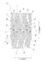
- FIG. 1 is a diagram illustrating an example of a tread pattern formed on a tread 11 of a pneumatic tire (hereinafter referred to as a tire) 10 according to the present embodiment, in which the vertical direction is the tire circumferential direction and the horizontal direction is the tire width direction.
- the tire 10 has at least one layer of carcass straddling a toroidal shape between a pair of beads, and has at least one belt layer on the radially outer side of the crown portion of the carcass, and on the radially outer side of the belt layer.
- a tread pattern as shown in FIG. 1 is formed on the surface of the arranged tread rubber.
- a region surrounded by two straight lines passing through the center of the contact width of the contact surface (not shown) and the contact end of the tire 10 and parallel to the tire circumferential direction is a center portion, and a region outside the center portion is a shoulder portion.
- the central circumferential groove 12 is a circumferential groove provided so as to extend along the tire circumferential direction substantially at the center in the tire width direction and communicate with the tire circumferential direction.
- the inner longitudinal grooves 13a and 13b are longitudinal grooves provided on the outer side in the tire radial direction of the central circumferential groove 12, respectively, and are not communicated with the tire circumferential direction in which the extending direction is substantially the circumferential direction.
- the outer longitudinal grooves 14a and 14b The longitudinal grooves 13a and 13b are provided on the outer side in the tire radial direction, and are not communicated with the tire circumferential direction in which the extending direction is substantially the circumferential direction.
- the term “groove that communicates” here refers to a groove whose groove extending direction is not inclined with respect to the tire circumferential direction, and “the groove that does not communicate” refers to a groove extending direction that is inclined with respect to the tire circumferential direction. (The angle between the extending direction of the groove and the tire circumferential direction is not 0 °).
- the inner longitudinal grooves 13a and 13b and the outer longitudinal grooves 14a and 14b are formed to be inclined by about 10 ° with respect to the tire circumferential direction.
- the lug groove 15 extends from one end (here, the right side) in the tire width direction toward the center in the tire width direction so as to intersect the tire circumferential direction and opens to the central circumferential groove 12.
- a left lug groove 15b that extends from the other end (left side) in the tire width direction toward the center in the tire width direction so as to intersect the tire circumferential direction and opens into the central circumferential groove 12. It is a letter-shaped groove.
- Both the right lug groove 15a and the left lug groove 15b are arc-shaped grooves, and are formed such that the groove width gradually increases from the main groove 12 side toward the outer side in the tire width direction.
- the right lug groove 15a extends upward as it goes from the central circumferential groove 12 to the outside in the tire width direction
- the left lug groove 15b extends upward.
- the central circumferential groove 12, the inner longitudinal grooves 13a, 13b, and the outer longitudinal grooves 14a, 14b are all disposed within the ground plane, and the central circumferential groove 12 and the inner longitudinal grooves 13a, 13b are disposed.
- the outer longitudinal grooves 14a and 14b are arranged in the shoulder portion at the center portion.
- the outer longitudinal grooves 14a and 14b are also referred to as shoulder grooves because they are disposed in the shoulder portion.
- the inner vertical grooves 13 a and 13 b are referred to as the inner vertical groove 13
- the outer vertical grooves 14 a and 14 b are referred to as the outer vertical groove 14.
- the surface of the tread 11 is partitioned into a plurality of blocks 16 (16a to 16c) by the central circumferential groove 12, the inner vertical groove 13, the outer vertical groove 14, and the lug groove 15 provided on the surface of the tread 11.
- a block 16 a that is partitioned by the central circumferential groove 12, the inner longitudinal groove 13, and the lug groove 15 and disposed at the center portion of the tire 10 is a center block
- the block 16c disposed in the section is referred to as a shoulder block
- the block 16b defined by the inner longitudinal groove 13, the outer longitudinal groove 14, and the lug groove 15 and disposed between the center block 16a and the shoulder block 16c is referred to as an intermediate block.
- a plurality of sipes 17a to 17c are provided on the grounding surface side which is the surface of each block 16a to 16c.
- the sipe 17a provided in the center block 16a is referred to as a center sipe
- the sipe 17b provided in the intermediate block 16b is referred to as an intermediate sipe
- the sipe 17c provided in the shoulder block 16c is referred to as a shoulder sipe.
- reference numeral 18 denotes a groove bottom raised portion provided at the center lug groove bottom of the center block 16a
- reference numeral 19 denotes a chamfered portion provided on the kick side of the center block 16a and the intermediate block 16b. .
- the on-snow ⁇ which is a coefficient of friction between the tire 10 and the road surface when running on a snowy road surface, is mainly a compression resistance F A as a running resistance acting on the front surface of the tire 10.
- the surface frictional force F B acting on the surface of the block 16 the snow column shearing force F C acting on the groove (here, the lug groove 15), and the scratching force F D (edge effect) due to the sipe edge and the block edge.
- the wet braking performance and the wear resistance performance are ensured, and the acceleration on the snow road and the braking performance and the steering stability performance are enhanced by increasing ⁇ on the snow. To improve.
- the central circumferential groove 12 is provided at the center of the center portion, and the inner longitudinal groove 13 is provided at the center portion and on the outer side in the tire width direction of the central circumferential groove 12 to thereby block the center block 16a and the intermediate block 16b.
- the edge effect by the edge is enhanced to increase the lateral grip force on the snow
- the central circumferential groove 12 is a groove that communicates with the tire circumferential direction to enhance drainage performance in the tire circumferential direction and ensure wet braking performance. Is possible.
- the groove width of the lug groove 15 is formed so as to gradually increase from the center portion to the shoulder portion.
- the block length of the center block 16a can be lengthened and the block rigidity of the center part can be ensured, the collapse of the block in the center part can be suppressed. Therefore, the wet braking performance on the paved road can be increased, and the wear resistance performance can be ensured.
- the shoulder portion by increasing the groove width of the lug groove 15, it is possible to increase the snow column shear force by the lug groove 15 which is insufficient in the center portion and to secure the front and rear grip rigidity on the snow. Acceleration performance can be improved.
- the groove width of the lug groove 15 gradually increases from the center portion toward the shoulder portion, the drainage effect on the shoulder side can be enhanced, and wet braking performance can be ensured.
- the lug groove width ratio which is the ratio of the groove width at the shoulder portion of the lug groove 15 to the groove width at the center portion, is preferably set to 105% to 500%.
- the lug groove width ratio is less than 105%, the groove width difference is small, so that the effect of changing the groove width cannot be obtained. Further, if the lug groove width ratio exceeds 500%, the lug groove width of the shoulder portion becomes too large, and the block rigidity of the shoulder portion is significantly reduced. As a result, the wet braking performance on the paved road is lowered.
- the inner vertical groove 13 and the outer vertical groove 14 are preferably narrow grooves whose groove width is narrower than that of the central circumferential groove 12.
- the narrow groove refers to a groove width in which the groove walls do not contact each other within the ground plane.
- the groove width of the narrow groove is preferably 20% to 60% of the groove depth. If the width is smaller than 20%, the groove walls come into contact with each other at the time of lateral input, and the horizontal block edge deformation on the snow is suppressed, and the edge effect due to the vertical groove cannot be secured. As a result, a sufficient frictional force cannot be secured on the snow and on the wet road surface.
- the groove width of the narrow groove is preferably 1.5 mm to 5.5 mm, and more preferably 3.0 mm to 4.5 mm. Further, it is important to make the sum of the area of the central circumferential groove 12 that is a vertical groove and the area of the inner vertical groove 13 smaller than the total area of the lug grooves 15 that are horizontal grooves. Thereby, the ratio of the lug groove 15 can be increased as compared with a tire having a conventional tread pattern at the same negative rate (groove area ratio). That is, since the area of the lug groove can be increased without increasing the negative rate (groove area ratio), the longitudinal force on the snow can be effectively ensured. Further, if the inner longitudinal groove 13 is arranged at the center portion, the longitudinal groove can be concentrated on the center of the grounding surface, so that the effect of the longitudinal groove can be obtained even at a low load with a small grounding shape.
- the rear load is smaller than the front load. It is also known that improving the lateral lateral force leads to an increase in stability factor and improving the F / R balance of the vehicle.
- the vertical groove can be concentrated in the center of the ground plane. Stability factor on snow can be increased. Therefore, not only the lateral grip on snow but also the F / R balance on snow can be improved, so that the on-snow steering stability performance can be improved comprehensively.
- the outer longitudinal groove 14, which is a longitudinal groove disposed in the shoulder portion, is preferably located within the ground contact width under both front and rear conditions when the vehicle is mounted, and is defined by JATMA for the tire size of the tire.
- Tire measurement conditions (with the tire attached to the applicable rim, in the case of passenger car tires, the internal pressure is 180 kPa, left at room temperature (15-30 ° C.) for 24 hours, then adjusted to the original internal pressure and measured again. In the case of shape measurement, it is within 30% to 80% of the maximum contact width under the static load radius measurement condition, that is, measured with a mass corresponding to 88% of the maximum load capacity of the tire. It is more preferable if it is located.
- the outer vertical groove 14 is disposed at a position exceeding 80% of the maximum ground contact width, the above-mentioned effect on improving the lateral snow grip cannot be obtained. Moreover, if it is arranged inside 30% of the maximum ground contact width, the block width of the intermediate block 16b becomes too small and the block rigidity is lowered. As a result, wet braking performance and wear resistance performance on the paved road deteriorate. End up. Accordingly, as in this example, if the center circumferential groove 12 and the inner longitudinal groove 13 are provided in the center portion and the outer longitudinal groove 14 is provided in the shoulder portion, both the front tire and the rear tire having different ground contact widths can be used. The above-described improvement in snow handling performance can be effectively realized.
- the groove depth of the inner vertical groove 13 is deeper than the groove depth of the outer vertical groove 14, and it is more preferable if lug groove 15> inner vertical groove 13> outer vertical groove 14.
- the lug groove 15 having the deepest groove depth can secure the acceleration performance on snow, and the lateral force in the rear load can be secured to the maximum by the central circumferential groove 12 and the inner longitudinal groove 13, so that the grounding shape is With a small rear load, the lateral edge effect in the center portion can be further increased. Therefore, since the stability factor on snow can be increased, not only the lateral grip on snow but also the F / R balance on snow can be improved.
- the groove depth of the inner vertical groove 13 is made deeper than the groove depth of the outer vertical groove 14, the lateral edge effect in the center portion can be further increased, so that the on-snow steering stability performance is further improved. Can be improved.
- the groove depth is preferably 60 to 100% for the inner longitudinal groove 13 and 30 to 90% for the outer longitudinal groove 14 when the lug groove 15 is 100%. If the vertical grooves 13 and 14 are shallower than 30%, the block edge is not deformed in the lateral direction on the snow, the edge effect by the vertical grooves 13 and 14 cannot be secured, and the snow handling stability performance deteriorates.
- the groove widths of the inner vertical groove 13 and the outer vertical groove 14 which are narrow grooves are preferably 30% to 80% of the groove depth of the lug groove 15.
- the cross-sectional area of the lug groove 15 (maximum depth ⁇ lug groove (center block)) is formed on the groove bottom on the center side (center circumferential groove 12 side) of the center block 16a among the groove bottoms of the lug grooves 15.
- the groove bottom raising part 18 which is 10% to 90% of the width) is provided.
- the cross-sectional area of the groove bottom raised portion 18 is smaller than 10% of the cross-sectional area of the lug groove 15, the effect of increasing the rigidity cannot be sufficiently obtained.
- the lug groove in the tire center portion does not function as a groove and a sufficient snow column shearing force cannot be obtained, and as a result, the longitudinal force on the snow is greatly reduced.
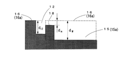
- the groove depth d 12 of the central circumferential groove 12 as well as deeper than the minimum depth d m of the groove bottom raising portion 18, a maximum of the lug groove 15 It is preferable that the depth is d M or less.
- the central circumferential groove 12 becomes a single communicating groove, so that drainage performance can be improved.
- the groove depth of the central circumferential groove 12 is set deeper than the minimum depth of the groove bottom raising part 18. And since it was shallower than the maximum groove depth of the lug groove 15, the rigidity of the center block 16a can be improved and a wet grip can be improved. Further, since the central circumferential groove 12 can be a single communicating groove, drainage performance can be enhanced.
- the groove wall angle on the kick side of the center block 16a of the lug groove 15 is set to the groove wall angle on the kick side of the intermediate block 16b and the shoulder block 16c.
- the groove wall angle on the kick side is made smaller than the average.
- the groove wall angle is also given to the stepping side, the volume of the lug groove 15 cannot be secured sufficiently, and the force on the snow is greatly reduced.
- the average value of the groove wall angle of the intermediate block 16b and the groove wall angle of the shoulder block 16c is preferably 5 ° to 25 °.
- the groove wall angle is smaller than 5 °, the effect of reinforcing the block rigidity is hardly obtained.
- the groove wall angle is larger than 25 °, the volume of the lug groove 15 cannot be sufficiently secured, and the longitudinal force on the snow is large. descend.
- the size of the groove wall angle of the lug groove 15 that defines the center block 16a is defined as the groove wall angle of the lug groove 15 that defines the intermediate block 16b and the groove wall angle of the lug groove 15 that defines the shoulder block 16c. Since the block rigidity in the tire circumferential direction can be further increased, the wet grip and the wear resistance can be further improved.
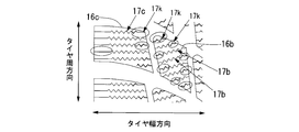
- the chamfered portion 19 (circled in FIG. 1) is formed by rounding the corner portion on the kick side on the outer side in the tire width direction of the center block 16a and the intermediate block 16b. Are provided).
- the range of R is preferably 0.5 mm ⁇ R ⁇ 5 mm.
- the chamfered portion 19 may also be provided at the corner portion of the kick side on the inner side in the tire width direction.
- the corners of the block serve as merging portions of water flowing through the lug grooves 15 and the inner longitudinal grooves 13 and between the lug grooves 15 and the outer longitudinal grooves 14.
- the peripheral edge length of the central peripheral groove 12 is greater than the peripheral edge length of the outer vertical groove 14.
- the circumferential edge length of the central circumferential groove 12 is preferably longer than the circumferential edge length of the inner longitudinal groove 13, and the circumferential edge length of the inner longitudinal groove 13 is greater than the circumferential edge length of the outer longitudinal groove 14. Longer is more preferable. In this way, by setting the peripheral edge length of the vertical groove on the grounding center side longer than the peripheral edge length of the vertical groove on the grounding end side, the lateral edge effect of the vertical groove is reduced at a rear load with a small grounding shape. It can be further increased.
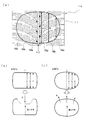
- the average ground contact length c of the shoulder block 16c inside the ground contact surface surrounded by the thick line in the same figure is smaller than the average ground contact length b of the intermediate block 16b. More preferably, the average ground contact length c of the shoulder block 16c is made smaller than the average ground contact length b of the intermediate block 16b, and the average ground contact length of the intermediate block 16b is made smaller than the average ground contact length a of the center block 16a.
- the average ground contact lengths of the center block 16a and the average ground contact length b of the middle block 16b are 85% to 95% of the average ground contact length a and the average ground contact length c of the shoulder block 16c, respectively.
- the ground contact shape in which the average contact lengths a, b, c of the blocks 16a to 16c are the same water easily enters and the drainage performance deteriorates.
- the ground contact shape with a>b> c provides a high drainage effect because water is easily discharged outward in the tire width direction. Therefore, by combining the pattern setting of the present invention and the ground contact shape contour, it is possible to obtain higher wet braking performance.
- the sipe angle of the center sipe 17a formed in the center block 16a (the angle formed by the sipe extension direction and the tire circumferential direction) is the center sipe angle
- the sipe angle of the intermediate sipe 17b formed in the intermediate block 16b is intermediate.
- the sipe angle is the shoulder sipe angle of the shoulder sipe 17c formed on the shoulder block 16c
- the center sipe angle is smaller than the shoulder sipe angle as shown in FIG.
- Each sipe angle is set so that becomes smaller than the center sipe angle.
- the shoulder sipes 17c face the direction closest to the tire width direction, so that the load on the front tire increases during braking of the tire and the contact area of the shoulder block 16c increases. As a result, the sipe edge effect is increased and the braking performance on snow is improved.
- the center block 16a located closest to the ground contact center when the tire starts the center sipe 17a faces the width direction next to the shoulder block 16c. As a result, the sipe edge effect is increased and the acceleration performance on snow is improved.
- the intermediate sipe 17b faces the direction closest to the tire circumferential direction, so that the sipe edge effect at the time of turning of the tire is increased, and the on-snow maneuvering stability performance is improved.
- the center sipe angle and the intermediate sipe angle are reduced to increase the lateral edge component, and the shoulder sipe angle is increased to ensure the longitudinal edge component, the acceleration performance on snow is improved.
- the steering stability performance on snow it is possible to improve the steering stability performance on snow.
- the intermediate sipe angle is preferably 45 ° to 80 °, and the shoulder sipe angle is preferably 90 ° (parallel to the tire width direction). Thereby, on-snow acceleration performance and on-snow handling stability can be further improved.
- the height of both reinforcements (the height at the bottom) is set to be different.
- the one with the higher bottom elevation is set to 50% or more of the maximum sipe depth
- the one with the lower bottom elevation is set to 50% or less.
- the setting of the bottom raising height in the place where the bottom raising reinforcement between the adjacent sipes (the bottom raising portion 17k) is performed does not overlap at least three sheets in the circumferential direction, and the above setting is performed. 50% or more of the total number of sipes in one block.
- the bottom is higher, it is preferably 50 to 100% of the maximum sipe depth, more preferably 60 to 90%.
- the lower bottom rise is preferably 0 to 50% of the maximum sipe depth, and more preferably 0 to 30%.
- the bottom height setting of adjacent sipes is set not to overlap at least 3 sheets in the circumferential direction. If the same setting overlaps, a part with extremely high / low rigidity is created locally at the block end. As a result, the balance between the block reinforcing effect and the effect of increasing the edge is biased, and the effect of raising the bottom cannot be obtained. It is more preferable that two or more sheets do not overlap.
- the sipe end setting is set to 50% or more of the number of sipes in one block, for example, in a narrow block width portion such as a block corner or in the center of the block, usually in order to ensure block rigidity. This is because a shallow 2D sipe may be set. A sufficient effect can be obtained if the bottom-up reinforcement is made 50% or more of the number of sipes in one block, but more preferably 70% or more.
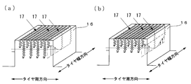
- the sipes 17a to 17c may be 2D sipes, or 3D sipes as shown in FIGS. 5 (a) and 5 (b). Also, the shape may be a straight sipe, or a wavy or broken line sipe.
- the block in which the 3D sipe is arranged has an effect of increasing the block rigidity in both the tire circumferential direction and the width direction as compared with the block having the 2D sipe on the sipe wall surface. That is, by arranging 3D sipes with irregularities in the depth direction on the block, high block rigidity can be obtained, and by suppressing unnecessary block deformation, particularly wet grip and wear resistance performance can be improved. it can.
- the 3D sipe is particularly effective to arrange the 3D sipe on the shoulder block 16c where the amount of block deformation increases. Moreover, it is preferable to arrange
- the effect of arranging the 3D sipes in the intermediate block 16b / center block 16a is not as good as the effect of arranging in the shoulder block 16c, but the effect of increasing the block rigidity as a whole is obtained. Note that if there are one or more sets of 3D sipes in a block, the block is defined as a block in which 3D sipes are arranged. [Example]
- the present invention will be described in detail below based on examples.
- the rim and internal pressure are based on an applicable rim and air pressure-load capacity correspondence table corresponding to the size of the radial ply tire defined in JATMA YEAR BOOK (2011, Japan Automobile Tire Association Standard).
- the tire size of the prototype tire is 195 / 65R15.
- the groove depth of the lug grooves was 9 mm, and the sipe depths were all 6 mm.
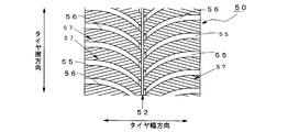
- the pattern shape of the conventional example only has the central circumferential groove 52 and the lug groove 55 whose groove width is equal in the center portion and the shoulder portion, and does not have the inner vertical groove and the outer vertical groove.
- the angles of the sipes 57 provided in the land portion 56 are all 15 °.
- the conventional lug groove width is 10 mm and the negative rate is 32%.
- all of the pattern shapes of Examples 1 to 55 have one central circumferential groove communicating with the center portion in the circumferential direction, and the shoulder portion lug groove width is larger than the center portion lug groove width.
- the relationship between the lug groove negative rate and the circumferential groove negative rate is such that lug groove negative ⁇ circumferential groove negative.
- the pattern shapes of Examples 1 to 55 will be described later.
- the number of sipes arranged in the center block and the intermediate block is eight.
- the first and eighth blocks in the circumferential direction of the block cannot secure the block rigidity, so that the sipe depth is 1 mm. It is reinforced with. Therefore, the sipe settings are changed in the middle six sheets. Since there are no reinforced shallow sipes in the shoulder block, all six are changed.
- the above tire was assembled on a 6J-15 rim at an internal pressure of 200 kPa, and mounted on a passenger car to perform acceleration performance test / steering stability performance test on snow, wet braking performance test on road surface, and wear resistance performance test. It was.
- the on-snow acceleration performance test is evaluated based on the time (acceleration time) from a stationary state until the accelerator is fully opened and traveling 50 meters.
- evaluation is conducted by measuring the lap time when driving on the course for snow maneuvering stability evaluation by an evaluation driver.
- wet braking performance test water with a depth of 2 mm is sprayed on the paved road surface, and the evaluation is performed on the braking distance from 60 km / h to complete rest.
- the track is run for 5000 km on the paved road, the tread rubber wear amount at each part from the center part of the tire to the shoulder part is measured, and the average value of the wear amount at each part is evaluated. (The smaller the amount of wear, the better).
- the test results are shown in the tables of FIGS. The test results are expressed as an index with the conventional example set to 100, and the index is good for each performance.
- the second embodiment is the same as the first embodiment except that the center lug groove width / shoulder lug groove width is 4/8 (200).
- the third embodiment is the same as the first embodiment except that the center lug groove width / shoulder lug groove width is 3/9 (300).
- the fourth embodiment is the same as the first embodiment except that the center lug groove width / shoulder lug groove width is 2/10 (500).
- the fifth embodiment is the same as the first embodiment except that the center lug groove width / shoulder lug groove width is 1.5 / 10.5 (700).
- a tire (Comparative Example 1) having a pattern in which the center lug groove width / shoulder lug groove width was 6/6 (100) was produced, and the same test was performed.
- the sixth embodiment is the same as the third embodiment except that the shoulder groove position is 25%.
- the seventh embodiment is the same as the third embodiment except that the shoulder groove position is 40%.
- the eighth embodiment is the same as the third embodiment except that the shoulder groove position is 80%.
- the ninth embodiment is the same as the third embodiment except that the shoulder groove position is 85%.
- the central circumferential groove width is 5.5 mm
- the inner longitudinal groove width is 5.5 mm
- the outer longitudinal groove width is 4.5 mm (negative rate: 32 // 13 // 19)
- the shoulder portion lug groove width is 2.7 / 8 (300), and the others are the same as in the third embodiment.
- Example 11 the central circumferential groove width is 6.5 mm, the inner longitudinal groove width is 6.5 mm, the outer longitudinal groove width is 4.5 mm (negative rate: 32 // 16 // 16), and the center lug groove width /
- the shoulder portion lug groove width is 2.3 / 7 (300), and the others are the same as in the third embodiment.
- the central circumferential groove width is 8 mm
- the inner longitudinal groove width is 8 mm
- the outer longitudinal groove width is 4.5 mm (negative rate: 32 // 17 // 15)
- the center lug groove width / shoulder A tire with a pattern in which the center lug groove width / shoulder lug groove width is 3/9 (300) with a part lug groove width of 2.3 / 7 (300) (Comparative Example 2) was produced and the same test was performed. It was.
- Example 12 is the same as Example 3 except that the center bottom raised portion area / center block groove area is 5%.
- Example 13 is the same as Example 3 except that the center bottom raised area / center block groove area was 10%.
- Example 14 is the same as Example 3 except that the center bottom raised portion area / center block groove area is 60%.
- Example 15 is the same as Example 3 except that the center bottom raised portion area / center block groove area was 90%.
- Example 16 is the same as Example 3 except that the center bottom raised portion area / center block groove area is 95%.
- the center sipe angle /// intermediate sipe angle // shoulder sipe angle is 85 // 75 // 85, and the others are the same as the third embodiment.
- the center sipe angle // intermediate sipe angle // shoulder sipe angle is 85 // 75 // 90.
- the average contact length a // b // c of the block is set to 100 // 100 // 110, and the rest is the same as the third embodiment.
- the embodiment 20 is the same as the embodiment 3 except that the average contact length a // b // c of the block is 100 // 105 // 90.
- the embodiment 21 is the same as the embodiment 3 except that the average contact length a // b // c of the block is 100 // 95 // 80.
- the embodiment 22 is the same as the embodiment 3 except that the average contact length a // b // c of the block is 100 // 85 // 70.
- the embodiment 23 is the same as the embodiment 3 except that the average contact length a // b // c of the block is 100 // 80 // 65.
- Example 24 (maximum raised / maximum sipe depth) // (minimum raised / maximum sipe depth) was 50 // 50, and the number of raised sipe / total sipe number in the block was 75%. Is the same as in Example 3.
- Example 25 (maximum bottom raising / maximum sipe depth) // (minimum bottom raising / maximum sipe depth) 60 // 40, the maximum number of adjacent sipes with the same bottom elevation is 0, and the number of bottom raising sipes in the block / The total number of sipes is 75%, and the others are the same as in the third embodiment.
- Example 26 (maximum bottom raising / maximum sipe depth) // (minimum bottom raising / maximum sipe depth) is 80 // 20, the maximum number of adjacent sipes having the same bottom elevation is zero, and the number of bottom raising sipes in the block / The total number of sipes is 75%, and the others are the same as in the third embodiment.
- Example 27 (maximum bottom raising / maximum sipe depth) // (minimum bottom raising / maximum sipe depth) is 100 // 0, the maximum number of adjacent sipes having the same bottom elevation is zero, and the number of bottom raising sipes in the block / The total number of sipes is 75%, and the others are the same as in the third embodiment.
- Example 28 (maximum bottom raising / maximum sipe depth) // (minimum bottom raising / maximum sipe depth) is 80 // 0, the maximum number of adjacent sipes with the same bottom elevation is 0, and the number of bottom raising sipes in the block / The total number of sipes is 75%, and the others are the same as in the third embodiment.
- Example 29 (maximum raising / maximum sipe depth) // (minimum raising / maximum sipe depth) is 80 // 0, the maximum number of adjacent sipes with the same elevation is two, and the number of raising sipe in the block / The total number of sipes is 75%, and the others are the same as in the third embodiment.
- Example 30 (maximum bottom lift / maximum sipe depth) // (minimum bottom lift / maximum sipe depth) is 80 // 0, the maximum number of adjacent sipes with the same bottom lift is three, and the number of bottom sipe in the block / The total number of sipes is 75%, and the others are the same as in the third embodiment.
- Example 31 (maximum bottom elevation / sipe maximum depth) // (minimum bottom elevation / sipe maximum depth) is 80 // 0, the maximum number of adjacent sipes with the same bottom elevation is 4, and the number of bottom-up sipes in the block / The total number of sipes is 75%, and the others are the same as in the third embodiment.
- Example 32 (maximum bottom raising / maximum sipe depth) // (minimum bottom raising / maximum sipe depth) is 80 // 0, the maximum number of adjacent sipes with the same bottom elevation is 0, and the number of bottom raising sipes in the block / The total number of sipes was 62.5%, and the others were the same as in Example 3.
- Example 33 (maximum bottom lift / sipe maximum depth) // (minimum bottom lift / sipe maximum depth) is 80 // 0, the maximum number of adjacent sipes with the same bottom lift is zero, and the number of bottom lift sipes in the block / The total number of sipes is 50%, and the others are the same as in the third embodiment.
- Example 34 (maximum raising / maximum sipe depth) // (minimum raising / maximum sipe depth) is 80 // 0, the maximum number of adjacent sipes with the same elevation is 0, and the number of sipes raising in the block / The total number of sipes was 37.5%, and the others were the same as in Example 3.
- Example 35 is the same as Example 3 except that the central circumferential groove depth // inner longitudinal groove depth // outer longitudinal groove depth is 6.5 // 9.0 // 8.1.
- the central circumferential groove depth // inner longitudinal groove depth // outer longitudinal groove depth was set to 6.5 // 7.2 // 5.4, and the others were the same as Example 3.
- the central circumferential groove depth // inner longitudinal groove depth // outer longitudinal groove depth was set to 6.5 // 5.4 // 2.7, and the others were the same as Example 3.
- Example 38 the central circumferential groove depth // inner longitudinal groove depth // outer longitudinal groove depth was set to 6.5 // 4.5 // 1.35, and the others were the same as Example 3.
- Example 39 the central circumferential groove width // inner longitudinal groove / width / outer longitudinal groove width was set to 2.5 // 2.5 // 4.5, and the others were the same as Example 3.
- Example 40 the central circumferential groove width // inner longitudinal groove / width / outer longitudinal groove width was set to 3.5 // 3.5 // 4.5, and the others were the same as Example 3.
- Example 41 is the same as Example 3 except that the groove wall angle of the intermediate and shoulder block lug grooves is 5 °.
- Example 42 is the same as Example 3 except that the groove wall angle of the intermediate and shoulder block lug grooves is 15 °.
- Example 43 is the same as Example 3 except that the groove wall angle of the intermediate and shoulder block lug grooves is 25 °.
- the groove wall angle of the intermediate and shoulder block lug grooves was set to 30 °, and the others were the same as Example 3.
- Example 45 is the same as Example 3 except that the kick side corners R of the center, middle and shoulder blocks are 0.3 mm.
- the example 46 is the same as the example 3 except that the kick side corners R of the center, middle and shoulder blocks are 0.5 mm.
- the embodiment 47 is the same as the embodiment 3 except that the kick side corner portion R of the center, middle and shoulder blocks is 2.5 mm.
- Example 48 is the same as Example 3 except that the kick side corners R of the center, middle and shoulder blocks are 5 mm.
- Example 49 is the same as Example 3 except that the kick side corners R of the center, middle and shoulder blocks are 6 mm.
- Example 50 is the same as Example 3 except that 3D sipes are provided on the shoulder block.
- Example 51 is the same as Example 3 except that 3D sipes are provided on the shoulder block and the intermediate block.
- the embodiment 52 is the same as the embodiment 3 except that all blocks are provided with 3D sipes.
- Example 53 is the same as Example 3 except that the central circumferential groove depth is 3.6 mm.
- Example 54 is the same as Example 3 except that the central circumferential groove depth is 5.4 mm.
- Example 55 is the same as Example 3 except that the central circumferential groove depth is 9.0 mm.
- the tires of Examples 1 to 5 in which the center lug groove width is larger than the shoulder lug groove width are snow acceleration performance, snow handling stability performance, wet braking performance, It was confirmed that all of the wear resistance performances were improved as compared with the conventional tires.
- the acceleration performance on snow, the stability performance on snow, and the wear resistance performance are higher as the shoulder lug groove width is larger than the center lug groove width.
- the wet braking performance is 300 mm, which is the shoulder lug groove width of the center lug groove width. %, And the center lug groove width and groove width are the same, the acceleration performance on snow and the stability performance on snow are improved, but the wet braking performance and wear resistance performance are the same as the conventional example.
- the shoulder lug groove width with respect to the center lug groove width is preferably in the range of 105 to 500% of the center lug groove width. .
- the shoulder groove position may be provided in a range of 25% to 85% of 1/2 of the maximum ground contact width from the center in the tire width direction.
- the relationship between the lag groove negative rate and the circumferential groove negative rate is such that the lag groove negative rate ⁇ the circumferential groove negative rate.
- Example 12 to 16 it was confirmed that when the bottom raised portion was provided at the center, the acceleration performance on snow and the stability performance on snow, or the wet braking performance and the wear resistance performance were improved.
- Example 3 and Examples 17 and 18 when the size of the sipe angle is set such that shoulder sipe angle> center sipe angle> intermediate sipe angle, snow acceleration performance and snow maneuvering are achieved. It was also confirmed that the stability performance was further improved.
- wet braking performance can be further improved if the average contact length b of the intermediate block is made larger than the average contact length c of the shoulder block. confirmed. Further, it was confirmed that wet braking performance and wear resistance performance were further improved by providing bottom raised portions at both ends of the sipe as in Examples 24 to 34.
- the inner longitudinal groove depth is made deeper than the outer longitudinal groove depth as in Examples 35 to 40, it is possible to ensure on-snow handling stability, and as in Examples 41 to 44, the intermediate block and shoulder block can be secured.
- the groove wall of the lug groove is angled, wet braking performance and wear resistance performance are further improved.
- the center, middle and shoulder block kick side corners R are provided, It was confirmed that wet braking performance was improved. It was also confirmed that wet braking performance and wear resistance performance were further improved by providing 3D sipes in the blocks as in Examples 50-52. From Examples 3 and 53 to 55, it can be seen that the central circumferential groove depth may be 40 to 100% of the lug groove depth.
Landscapes
- Engineering & Computer Science (AREA)
- Mechanical Engineering (AREA)
- Tires In General (AREA)
Abstract
Description
また、これに加えて、弾性率の小さいゴム(軟ゴム)をトレッドゴムに使用することで、雪道における操縦安定性を改良する試みもなされてきた。
また、ゴム弾性率を小さくした場合もブロック剛性が低下するので、舗装路でのウェット制動性能、耐摩耗性能が低下するといった問題点があった。
ここで、溝面積とは、タイヤのトレッドパターンを平面展開した際の平面上での溝面積を意味する。また、溝面積とトレッドパターンの全面積との比をネガティブ率(溝面積/パターン全面積)と定義する場合、前述の溝面積の関係は、ラグ溝ネガティブ率≧周方向溝ネガティブ率となる。
なお、図1に示すような、右上がりのラグ溝のタイヤ幅方向中心部側の開口部の位置と左上がりのラグ溝のタイヤ幅方向中心部側の開口部の位置とがタイヤ周方向にずれているようなラグ溝も、本発明の「タイヤ幅方向の一方の端部からタイヤ幅方向中心部に向かってタイヤ周方向に交差するように延長し、タイヤ幅方向中心部にて折り返してタイヤ幅方向の他方の端部まで延長するラグ溝」に含まれるものとする。
図1は本実施の形態に係る空気入りタイヤ(以下、タイヤという)10のトレッド11に形成されたトレッドパターンの一例を示す図で、上下方向がタイヤ周方向、左右方向がタイヤ幅方向である。
タイヤ10は、一対のビード間にトロイダル状に跨る少なくとも1層のカーカスを骨格とし、このカーカスのクラウン部の径方向外側に少なくとも1層のベルト層を有し、このベルト層の径方向外側に配置されたトレッドゴム表面に、図1に示すような、トレッドパターンが形成される。
以下、当該タイヤ10の図示しない接地面の接地幅中心と接地端との中心を通りタイヤ周方向に平行な2直線で囲まれた領域をセンター部、前記センター部の外側の領域をショルダー部とする。
中央周溝12は、タイヤ幅方向のほぼ中心にタイヤ周方向に沿って延長しタイヤ周方向に連通するように設けられた周方向溝である。
内側縦溝13a,13bは、中央周溝12のタイヤ径方向外側にそれぞれ設けられた、延長方向がほぼ周方向であるタイヤ周方向に連通しない縦溝で、外側縦溝14a,14bは、内側縦溝13a,13bのタイヤ径方向外側にそれぞれ設けられた、延長方向がほぼ周方向であるタイヤ周方向に連通しない縦溝である。
ここでいう「連通する溝」とは、溝の延長方向がタイヤ周方向に対して傾斜していない溝で、「連通しない溝」とは、溝の延長方向がタイヤ周方向に対して傾斜している(溝の延長方向とタイヤ周方向とのなす角度が0°でない)溝を指す。
本例では、内側縦溝13a,13bと外側縦溝14a,14bとをタイヤ周方向に対して約10°傾けて形成した。
ラグ溝15は、タイヤ幅方向の一方(ここでは、右側)の端部からタイヤ幅方向中心部に向かってタイヤ周方向に交差するように延長して中央周溝12に開口する右側ラグ溝15aと、タイヤ幅方向の他方(左側)の端部からタイヤ幅方向中心部に向かってタイヤ周方向に交差するように延長して中央周溝12に開口する左側ラグ溝15bとを備えたほぼV字状の溝である。
右側ラグ溝15aと左側ラグ溝15bとは、いずれも、円弧状の溝で、主溝12側からタイヤ幅方向外側に行くにしたがって溝幅が次第に広がるように形成されている。図1のパターンでは、右側ラグ溝15aは、中央周溝12からタイヤ幅方向外側に行くにしたがって右上がりに延長し、左側ラグ溝15bは左上がりに延長している。
本例では、中央周溝12と内側縦溝13a,13bと外側縦溝14a,14bとを全て接地面内に位置するように配置するとともに、中央周溝12と内側縦溝13a,13bとをセンター部に配置し、外側縦溝14a,14bをショルダー部に配置した。外側縦溝14a,14bはショルダー部に配置されるのでショルダー溝ともいう。
以下、左右を区別しない場合には、内側縦溝13a,13bを内側縦溝13、外側縦溝14a,14bを外側縦溝14と記す。
中央周溝12と内側縦溝13とラグ溝15とにより区画されてタイヤ10のセンター部に配置されるブロック16aをセンターブロック、外側縦溝14とラグ溝15とにより区画されてタイヤ10のショルダー部に配置されるブロック16cをショルダーブロック、内側縦溝13と外側縦溝14とラグ溝15とにより区画されてセンターブロック16aとショルダーブロック16cとの間に配置されるブロック16bを中間ブロックという。
各ブロック16a~16cの表面である接地面側には、それぞれ複数のサイプ17a~17cが設けられている。以下、センターブロック16aに設けられたサイプ17aをセンターサイプ、中間ブロック16bに設けられたサイプ17bを中間サイプ、ショルダーブロック16cに設けられたサイプ17cをショルダーサイプという。
なお、図1において、符号18は、センターブロック16aのセンター側のラグ溝底に設けられた溝底上げ部、符号19は、センターブロック16aと中間ブロック16bの蹴り側に設けられた面取り部である。
本例では、図1に示すようなトレッドパターンを採用することにより、ウェット制動性能と耐摩耗性能とを確保するとともに、雪上μを高めて雪道における加速性能・制動性能、及び、操縦安定性能を向上させるようにしている。
具体的には、センター部の中心に中央周溝12を設けるとともに、センター部でかつ中央周溝12のタイヤ幅方向外側に内側縦溝13を設けることで、センターブロック16aと中間ブロック16bのブロックエッジによるエッジ効果を高めて雪上横グリップ力を高めるともに、中央周溝12をタイヤ周方向に連通する溝とすることで、タイヤ周方向への排水性能を高めてウェット制動性能についても確保することを可能にしている。
これにより、センター部においては、センターブロック16aのブロック長を長くして、センター部のブロック剛性を確保することができるので、センター部におけるブロックの倒れ込みを抑制できる。したがって、舗装路におけるウェット制動性能を増大させることができるとともに、耐摩耗性能についても確保することができる。
一方、ショルダー部では、ラグ溝15の溝幅を広くすることで、センター部で不足するラグ溝15による雪柱剪断力を増加させて雪上での前後グリップ剛性を確保することができるので、雪上加速性能を向上させることができる。また、ラグ溝15の溝幅がセンター部からショルダー部に行くにしたがって次第に広がっているので、ショルダー側への排水効果を高めることができ、ウェット制動性能を確保することができる。
このように、本例では、ラグ溝15のショルダー部の溝幅をセンター部の溝幅よりも広くすることで、雪上での前後方向のグリップ力と雪柱剪断力とをともに確保できるようにしたので、舗装路でのウェット制動性能を確保しつつ、雪上路面における操縦安定性能を向上させることができる。
なお、ラグ溝15のショルダー部における溝幅のセンター部における溝幅に対する比であるラグ溝幅比を105%~500%とすることが好ましい。ラグ溝幅比が105%未満である場合には、溝幅差が小さいので、上記の溝幅を変化させた効果が得られない。また、ラグ溝幅比が500%を超えると、ショルダー部のラグ溝幅が大きくなりすぎてショルダー部のブロック剛性が大幅に低下し、その結果、舗装路におけるウェット制動性能が低下する。
また、縦溝である中央周溝12の面積と内側縦溝13の面積との和を、横溝であるラグ溝15の総面積よりも小さくすることが肝要である。これにより、同一ネガティブ率(溝面積比率)での従来のトレッドパターンを有するタイヤと比較してラグ溝15の比率を大きくすることができる。すなわち、ネガティブ率(溝面積比率)を上げることなく、ラグ溝の面積を大きくできるので、雪上での前後力を効果的に確保することができる。また、内側縦溝13をセンター部に配置すれば、縦溝を接地面の中央に集中して配置できるので、接地形状が小さい低荷重時においても縦溝の効果を得ることができる。
つまり、ショルダー部に配置された縦溝である外側縦溝14は、車両装着時のフロント、リアいずれの条件でも接地幅内に位置することが好ましく、当該タイヤのタイヤサイズにおけるJATMAで規定されるタイヤの測定条件(タイヤを適用リムに装着し、乗用車用タイヤの場合は内圧を180kPaとし、室温(15~30℃)で24時間放置した後、再び元の内圧に調整して測定する。接地形状計測の場合は、静的負荷半径計測条件、すなわち、そのタイヤの最大負荷能力の88%に相当する質量を負荷した状態で測定する)での最大接地幅の30%以上、80%以内に位置すれば更に好ましい。
外側縦溝14が最大接地幅の80%を超えた位置に配置されると、上述した雪上横グリップ向上効果が得られない。また、最大接地幅の30%より内側に配置されると、中間ブロック16bのブロック幅が小さくなりすぎてブロック剛性が低下し、その結果、舗装路でのウェット制動性能、耐摩耗性能が悪化してしまう。したがって、本例のように、センター部に中央周溝12と内側縦溝13を設けるとともに、ショルダー部に外側縦溝14を設ける構成とすれば、接地幅が異なるフロントタイヤ、リアタイヤのいずれにおいても、上述した雪上操安性能の向上を効果的に実現することができる。
このように、内側縦溝13の溝深さを外側縦溝14の溝深さよりも深くすれば、センター部における横方向のエッジ効果をより一層増大させることができるので、雪上操縦安定性能を更に向上させることができる。
また、溝深さは、ラグ溝15を100%としたときに、内側縦溝13が60~100%、外側縦溝14が30~90%が望ましい。縦溝13,14が30%よりも浅いと、雪上で横方向にブロックエッジが変形せず、縦溝13,14によるエッジ効果を確保できなくなり、雪上操縦安定性能が悪化する。
また、細溝である内側縦溝13と外側縦溝14の溝幅は、ラグ溝15の溝深さの30%~80%とすることが好ましい。30%よりも小さいと、横入力時に細溝の溝壁同士が接触して雪上で横方向のブロックエッジ変形が抑制されてしまい、縦溝によるエッジ効果を確保できなくなるだけでなく、ウェット排水性も確保できなくなるためである。一方、80%よりも大きいと接地面積が減少して雪上及びウェット路面において摩擦力を十分に確保できなくなる。
溝底上げ部18を設けると、センターブロック16aの剛性を更に増加させることができるので、ブロックの倒れ込みが抑制されウェットグリップが更に向上する。したがって、舗装路におけるウェット制動性能と耐摩耗性能を更に向上させることができる。
なお、溝底上げ部18の断面積がラグ溝15の断面積の10%よりも小さいと、剛性増加の効果が十分に得られない。また、90%を超えると、タイヤセンター部のラグ溝が溝として機能しなくなって十分な雪柱剪断力が得られず、その結果、雪上前後力が大幅に低下する。
図3に示すように、溝底上げ部18を設けた場合には、中央周溝12の溝深さd12を溝底上げ部18の最小深さdmよりも深くするとともに、ラグ溝15の最大深さdM以下とすることが好ましい。これにより、中央周溝12が1本の連通した溝となるので、排水性能を高めることができる。
また、中央周溝12の溝深さd12としては、ラグ溝15の最大深さdMと同等とすることが排水性能を高める上では効果的であるが、センターブロック16aの剛性を高めてウェットグリップを高めるためには、溝深さd12をラグ溝15の最大深さdMよりも浅い設定にすることが効果的である。すなわち、中央周溝12の溝深d12としては、ラグ溝15の最大深さdMの60~100%とすることが望ましい。
このように、ラグ溝15の断面積の10%以上90%以下の断面積を有する溝底上げ部18を設けるとともに、中央周溝12の溝深さを、溝底上げ部18の最小深さよりも深くし、かつ、ラグ溝15の最大溝深さよりも浅くしたので、センターブロック16aの剛性を高めてウェットグリップを高めることができる。また、中央周溝12を1本の連通した溝とすることができるので、排水性能を高めることができる。
ブロックの蹴り側のラグ溝に溝壁角度を付けると、タイヤ周方向のブロック剛性を高める効果が得られるので無駄なブロック変形を抑制でき、特にウェットグリップ,耐摩耗性能を向上させることができる。
ブロックの蹴り側にのみに溝壁角度を付けるのは、ブロックが接地面から蹴り出される際の変形が蹴り側で大きいためである。踏込み側にも溝壁角度を付けると、ラグ溝15の体積が十分に確保できなくなり、雪上前後力が大きく低下するので、ブロックを補強するには、本例のように、ブロックの蹴り側にのみに溝壁角度を付けるのが最も効果的である。
中間ブロック16bの溝壁角度とショルダーブロック16cの溝壁角度の平均値としては、5°~25°とすることが好ましい。溝壁角度が5°より小さい値では、ほとんどブロック剛性を補強する効果が得られず、一方で25°よりも大きい値では、ラグ溝15の体積が十分に確保できなくなり、雪上前後力が大きく低下する。
このように、センターブロック16aを区画するラグ溝15の溝壁角度の大きさを、中間ブロック16bを区画するラグ溝15の溝壁角度とショルダーブロック16cを区画するラグ溝15の溝壁角度との平均値よりも小さくすれば、タイヤ周方向のブロック剛性を更に高めることができるので、ウェットグリップ,耐摩耗性能を更に向上させることができる。
ブロックの角部は、ラグ溝15と内側縦溝13及びラグ溝15と外側縦溝14とに流れる水の合流部となる。したがって、この合流部であるブロックの角部に角丸め処理を行うことで、整流効果が得られ、ウェットグリップが向上する。
角部のRの最小値を0.5としたのは、これより小さなRでは整流効果が得られないためであり、最大値を5としたのは、これより大きなRではブロック自体が小さくなってブロック剛性が低下し、ウェットグリップが低下してしまうためである。
このように、接地中心側の縦溝の周エッジ長を接地端側の縦溝の周エッジ長に比べて長く設定することにより、接地形状が小さいリア荷重において縦溝の横方向のエッジ効果をより一層増大させることができる。その結果、リア荷重における横力をより一層向上させ、雪上でのスタビリティファクターを増大させることにより、雪上横グリップだけでなく雪上F/Rバランスも向上させることができるので、雪上操縦安定性能を総合的に向上させることができる。
また接地形状を矩形から丸型に近づけることができるので、接地面回りの排水性が向上するため、ウェット性能も向上させることが出来る。
図4(b)に示すように、各ブロック16a~16cの平均接地長a,b,cが同じであるような接地形状では、水が入り込みやすく排水性が悪化する。これに対して、図4(c)に示すように、a>b>cとした接地形状は、水がタイヤ幅方向外側に排出され易いため、高い排水効果が得られる。したがって、本発明のパターン設定と、接地形状輪郭を組み合わせることによって、更に高いウェット制動性能を得ることが可能となる。
ここで、センターブロック16aに形成されるセンターサイプ17aのサイプ角(サイプの延長方向とタイヤ周方向とのなす角度)をセンターサイプ角、中間ブロック16bに形成される中間サイプ17bのサイプ角を中間サイプ角とし、ショルダーブロック16cに形成されるショルダーサイプ17cのサイプ角をショルダーサイプ角としたとき、本例では、図1に示すように、センターサイプ角がショルダーサイプ角よりも小さく、中間サイプ角がセンターサイプ角よりも小さくなるように各サイプ角を設定している。
すなわち、ショルダーブロック16cではショルダーサイプ17cがタイヤ幅方向に最も近い方向を向くことになるので、タイヤ制動時にはフロントタイヤの荷重が増加してショルダーブロック16cの接地面積が増加する。その結果、サイプエッジ効果が増加し、雪上制動性能が向上する。
一方、タイヤ発進時に最も接地中心付近に位置するセンターブロック16aでは、センターサイプ17aがショルダーブロック16cの次に幅方向を向くことになる。その結果、サイプエッジ効果が増加し、雪上加速性能が向上する。
また、中間ブロック16bでは、中間サイプ17bがタイヤ周方向に最も近い方向を向くことになるので、タイヤ旋回時のサイプエッジ効果が増加し、雪上操縦安定性能が向上する。
このように、センターサイプ角や中間サイプ角を小さくして横方向のエッジ成分を増加させ、ショルダーサイプ角を大きくして前後方向のエッジ成分を確保するようにすれば、雪上加速性能を向上させることができるとともに、雪上操縦安定性能を向上させることができる。
なお、中間サイプ角としては45°以上80°以下、ショルダーサイプ角としては90°(タイヤ幅方向に平行)とすることが好ましい。
これにより、雪上加速性能と雪上操縦安定性とを更に向上させることができる。
そこで、本例では、上記のエッジ効果とブロック剛性の背反を解決するため、例えば、図5(a)に示すように、サイプの一端のみに底上げ補強を行うか、もしくは、図5(b)に示すような底上げ補強を行うようにしている。サイプの両端を底上げ補強する場合は、双方の補強高さ(底上げ高さ)を異なるように設定する。本例では、底上げの高い方を当該サイプ最大深さの50%以上とし、底上げの低い方を50%以下とした。
また、図6に示すように、隣り合うサイプ同士の底上げ補強を行った箇所(底上げ部17k)における底上げ高さの設定が、周方向で少なくとも3枚以上重ならないようにするとともに、上記設定を1つのブロック内の総サイプ本数の50%以上になるようにした。
なお、ブロック端部のように陸部幅が狭い箇所に配置されるサイプについては、ブロック剛性を高めるため、サイプ全体を底上げしてもよい。
このように、サイプ端の一方に強い補強を入れることでブロック剛性を高めることができるとともに、補強が弱い側ではエッジ効果を高めることができるので、ブロック剛性-ウェットグリップ・耐摩耗性能を向上させつつ、エッジ効果-雪上グリップを確保することができる。
なお、底上げの高い方をサイプ最大深さの50%以上としたのは、50%未満にすると十分なブロック補強効果が得られないためであり、底上げの低い方をサイプ最大深さの50%以下としたのは、底上げの低い方が50%を超えると、十分なエッジ効果が得られないためである。
底上げの高い方は、サイプ最大深さの50~100%とすることが好ましく、60~90%とすると更に好ましい。一方、底上げの低い方は、サイプ最大深さの0~50%とすることが好ましく、0~30%とすると更に好ましい。
また隣合うサイプ同士の底上げ高さの設定を、周方向で少なくとも3枚以上重ならないようにしたのは、同じ設定が重なり合うとブロック端部に局所的に極端に剛性が高い/低い部分ができてしまうので、ブロック補強効果とエッジを高める効果のバランスが偏ってしまい底上げの効果が得られなくなるためである。なお、2枚以上重ならないようにすれば、更に好ましい。
また、サイプ両端設定を1つのブロック内のサイプ本数の50%以上としたのは、例えば、ブロック角部のようにブロック幅が狭い箇所やブロック中央部には、ブロック剛性確保のために通常ごく浅い2Dサイプを設定する場合があるためである。底上げ補強が1つのブロック内のサイプ本数のうち50%以上なされていれば十分な効果が得られるが、70%以上にすれば更に好ましい。
3Dサイプが配置されたブロックは、サイプ壁面に2Dサイプを有するブロックに比べて、タイヤ周方向/幅方向ともにブロック剛性を高める効果が得られる。すなわち、深さ方向に凹凸のある3Dサイプをブロックに配置することで、高いブロック剛性を得ることができ、無駄なブロック変形を抑制することで、特にウェットグリップ、耐摩耗性能を向上させることができる。
3Dサイプは、特にブロック変形量が大きくなるショルダーブロック16cに配置することが効果的である。また、3Dサイプを中間ブロック16bにも配置することが好ましく、センターブロック16aにも配置すれば更に好ましい。中間ブロック16b/センターブロック16aに3Dサイプを配置した効果は、ショルダーブロック16cに配置した効果には及ばないが、全体としてブロック剛性を高める効果が得られる。
なお、ブロック内に1組以上の3Dサイプがあれば、3Dサイプが配置されたブロックであると規定する。
[実施例]
リム及び内圧は、JATMA YEAR BOOK(2011、日本自動車タイヤ協会規格)にて定めるラジアルプライタイヤのサイズに対応する適用リム及び空気圧-負荷能力対応表に基づく。
試作したタイヤのタイヤサイズは195/65R15である。ラグ溝の溝深さは9mm、サイプ深さは全て6mmとした。
従来例のパターン形状は、図6に示すように、中央周溝52と溝幅がセンター部とショルダー部とで等しいラグ溝55とを有するのみで、内側縦溝と外側縦溝を持たず、陸部56に設けられるサイプ57の角度は全て15°である。なお、従来例のラグ溝幅は10mmで、ネガティブ率は32%である。
実施例1~55のパターン形状は、全て、図1に示すように、センター部に周方向に連通する1本の中央周溝を有し、ショルダー部ラグ溝幅がセンター部ラグ溝幅より大であり、センター部よりショルダー部側に、左右2本ずつの、周方向に連通しない略周方向の周細溝を有し、ショルダー部に配置された周細溝は接地面の内側にあるように配置されており、ラグ溝ネガティブ率と周方向溝ネガティブ率の関係が、ラグ溝ネガティブ≧周方向溝ネガティブである。
実施例1~55のパターン形状については後述する。
なお、本実施例では、センターブロック及び中間ブロックに配置されたサイプ枚数は8枚であるが、ブロック周方向の1枚目と8枚目は、ブロック剛性が確保できないために、サイプ深さ1mmで補強してある。ゆえに、サイプ設定を変更するのは、中間の6枚となる。ショルダーブロックにおいては、補強浅サイプがないため全て6枚を変更する。
雪上加速性能テストは静止状態からアクセルを全開し、50m走行するまでの時間(加速タイム)で評価を行っている。雪上操縦安定性能テストでは評価ドライバーによる雪上操縦安定性能評価用コースを走行したときのラップタイムを計測して評価を行っている。ウェット制動性能テストは舗装路面上に水深2mmの水を散布し、この上で時速60km/hから完全静止までの制動距離で評価を行っている。耐摩耗性能テストでは、コースが定められた舗装路を5000km走行させ、タイヤのセンター部からショルダー部までの各部でのトレッドゴムの摩耗量を計測し、該各部の摩耗量の平均値で評価を行った(摩耗量小ほど良好となる)。
テスト結果を図7及び図8の表に示す。なお、テストの結果は従来例を100とした指数で表現し、各性能ともに指数大が良である。
実施例1
・ネガティブ率(%)
全ネガティブ率//周方向溝ネガティブ率//ラグ溝ネガティブ率=32//10//22
・平均ラグ溝幅(mm)
センター部ラグ溝幅/ショルダー部ラグ溝幅=5.85/6.15 (105)
( )内は、センター部ラグ溝幅を100とした時のショルダー部ラグ溝幅(%)
・ショルダー溝位置=60%
ショルダー溝位置は、最大接地幅の1/2に対する幅方向中心から外側縦溝までの距離
・センター底上げ部面積/センターブロック溝面積=30%
・センター底上げ部最小深さ=4mm
・周溝深さ(mm)
中央周溝//内側縦溝//外側縦溝=6.5//6.5//6.5
・周溝幅(mm)
中央周溝//内側縦溝//外側縦溝=4.5//4.5//4.5
・センターブロックラグ溝角度=4 °
・中間及びショルダーブロックのラグ溝角度=4 °
・センター及び中間及びショルダーブロックの蹴り側角部R=なし
・ブロックの平均接地長(センターブロックを100とした)
a//b//c=100//100//100
・サイプ角度(°)
センターサイプ角//中間サイプ角//ショルダーサイプ角=75//75//75
・サイプ底上げ(%)
(最大底上げ/サイプ最大深さ)//(最小底上げ/サイプ最大深さ)=0//0
・底上げが同じサイプが隣接する枚数の最大数(枚)=6
・ブロック内における底上げサイプ数/総サイプ数(%)=0
・3Dサイプの有無
センターブロック//中間ブロック//ショルダーブロック=無//無//無
なお、比較のため、センター部ラグ溝幅/ショルダー部ラグ溝幅を6/6 (100)としたパターンのタイヤ(比較例1)を作製し、同様の試験を行った。
実施例6は、ショルダー溝位置を25%としたもので、他は実施例3と同じである。実施例7は、ショルダー溝位置を40%としたもので、他は実施例3と同じである。実施例8は、ショルダー溝位置を80%としたもので、他は実施例3と同じである。実施例9は、ショルダー溝位置を85%としたもので、他は実施例3と同じである。
実施例10は、中央周溝幅を5.5mm、内側縦溝幅を5.5mm、外側縦溝幅を4.5mm(ネガティブ率;32//13//19)とし、かつ、センター部ラグ溝幅/ショルダー部ラグ溝幅を2.7/8 (300)としたもので、他は実施例3と同じである。実施例11は、中央周溝幅を6.5mm、内側縦溝幅を6.5mm、外側縦溝幅を4.5mm(ネガティブ率;32//16//16)とし、かつ、センター部ラグ溝幅/ショルダー部ラグ溝幅を2.3/7 (300)としたもので、他は実施例3と同じである。
なお、比較のため、中央周溝幅を8mm、内側縦溝幅を8mm、外側縦溝幅を4.5mm(ネガティブ率;32//17//15)とし、かつ、センター部ラグ溝幅/ショルダー部ラグ溝幅を2.3/7 (300)としたセンター部ラグ溝幅/ショルダー部ラグ溝幅を3/9 (300)としたパターンのタイヤ(比較例2)を作製し、同様の試験を行った。
実施例17は、センターサイプ角//中間サイプ角//ショルダーサイプ角を85//75//85としたもので、他は実施例3と同じである。実施例18は、センターサイプ角//中間サイプ角//ショルダーサイプ角を85//75//90としたもので、他は実施例3と同じである。
実施例19は、ブロックの平均接地長a//b//cを100//100//110としたもので、他は実施例3と同じである。実施例20は、ブロックの平均接地長a//b//cを100//105//90としたもので、他は実施例3と同じである。実施例21は、ブロックの平均接地長a//b//cを100//95//80としたもので、他は実施例3と同じである。実施例22は、ブロックの平均接地長a//b//cを100//85//70としたもので、他は実施例3と同じである。実施例23は、ブロックの平均接地長a//b//cを100//80//65としたもので、他は実施例3と同じである。
実施例45は、センター及び中間及びショルダーブロックの蹴り側角部Rを0.3mmとしたもので、他は実施例3と同じである。実施例46は、センター及び中間及びショルダーブロックの蹴り側角部Rを0.5mmとしたもので、他は実施例3と同じである。実施例47は、センター及び中間及びショルダーブロックの蹴り側角部Rを2.5mmとしたもので、他は実施例3と同じである。実施例48は、センター及び中間及びショルダーブロックの蹴り側角部Rを5mmとしたもので、他は実施例3と同じである。実施例49は、センター及び中間及びショルダーブロックの蹴り側角部Rを6mmとしたもので、他は実施例3と同じである。
実施例53は、中央周溝深さを3.6mmとしたもので、他は実施例3と同じである。実施例54は、中央周溝深さを5.4mmとしたもので、他は実施例3と同じである。実施例55は、中央周溝深さを9.0mmとしたもので、他は実施例3と同じである。
また、実施例3及び実施例6~9のように、ショルダー溝位置はタイヤ幅方向中心から最大接地幅の1/2の25%~85%の範囲に設ければよいことも確認された。
また、実施例3,10,11と比較例2とを比較して分かるように、ラグ溝ネガティブ率と周方向溝ネガティブ率との関係が、ラグ溝ネガティブ率≧周方向溝ネガティブ率である場合には、雪上加速性能、雪上安定性能、ウェット制動性能、耐摩耗性能の全てが従来例よりも向上するが、比較例2のように、ラグ溝ネガティブ率<周方向溝ネガティブ率とすると、中央周溝と4本の周細溝とを設け、かつ、ショルダー部ラグ溝幅をセンター部ラグ溝幅より大きくしても、上記の性能が従来例よりあまり向上しないことが確認された。
また、実施例3と実施例17,18とを比較してわかるように、サイプ角の大きさを、ショルダーサイプ角>センターサイプ角>中間サイプ角のように設定すると、雪上加速性能と雪上操縦安定性能とが更に向上することも確認された。
また、実施例3と実施例19~23とを比較してわかるように、中間ブロックの平均接地長bをショルダーブロックの平均接地長cよりも大きくすれば、ウェット制動性能が更に向上することが確認された。
また、実施例24~34のように、サイプの両端に底上げ部を設ければ、ウェット制動性能と耐摩耗性能とが更に向上することが確認された。
また、実施例50~52のように、ブロックに3Dサイプを設ければ、ウェット制動性能と耐摩耗性能とが更に向上することも確認できた。
なお、実施例3,53~55から、中央周溝深さとしては、ラグ溝深さの40~100%であればよいことが分かる。
13,13a,13b 内側縦溝、14,14a,14b 外側縦溝、
15 ラグ溝、15a 右側ラグ溝、15b 左側ラグ溝、
16a センターブロック、16b 中間ブロック、
16c ショルダーブロック、17a センターサイプ、
17b 中間サイプ、17c ショルダーサイプ、18 溝底上げ部、
19 面取り部。
Claims (14)
- タイヤのトレッドの表面に、タイヤ幅方向の一方の端部からタイヤ幅方向中心部に向かってタイヤ周方向に交差するように延長し、タイヤ幅方向中心部にて折り返してタイヤ幅方向の他方の端部まで延長するラグ溝が形成された空気入りタイヤであって、
前記タイヤの接地幅中心に位置してタイヤ周方向に延長する中央周溝と、
前記中央周溝のタイヤ幅方向外側でかつ当該タイヤの接地面内に形成された複数の縦溝と、
前記中央周溝と前記縦溝と前記ラグ溝、もしくは、前記縦溝と前記ラグ溝とにより区画された複数の陸部と、
前記陸部に設けられた複数のサイプと、を備え、
当該タイヤの接地面の接地幅中心と接地端との中心を通りタイヤ周方向に平行な2直線で囲まれた領域をセンター部、前記センター部の外側の領域をショルダー部としたとき、
前記ラグ溝の前記ショルダー部における溝幅が前記センター部における溝幅よりも大きく、
前記中央周溝の溝面積と前記複数の縦溝の溝面積との和が前記ラグ溝の溝面積よりも小さいことを特徴とする空気入りタイヤ。 - 前記複数の縦溝が、前記中央周溝のタイヤ幅方向外側にそれぞれ形成された内側縦溝と、前記内側縦溝のタイヤ幅方向外側にそれぞれ形成された外側縦溝であり、
前記中央周溝と前記内側縦溝と前記ラグ溝とにより区画されて当該タイヤの中央部に配置されるブロックをセンターブロック、前記外側縦溝と前記ラグ溝とにより区画されて当該タイヤのショルダー部に配置されるブロックをショルダーブロック、前記内側縦溝と前記外側縦溝と前記ラグ溝とにより区画されて前記センターブロックと前記ショルダーブロックとの間に配置されるブロックを中間ブロックとしたとき、
前記センターブロックを区画するラグ溝の溝幅が、前記ショルダーブロックを区画するラグ溝の溝幅よりも小さく、
前記センターブロックを区画するラグ溝のタイヤ幅方向中心側の溝底に、当該ラグ溝の断面積の10%以上90%以下の断面積を有する溝底上げ部が設けられていることを特徴とする請求項1に記載の空気入りタイヤ。 - 前記複数の縦溝を、前記中央周溝のタイヤ幅方向外側にそれぞれ形成された内側縦溝と、前記内側縦溝のタイヤ幅方向外側にそれぞれ形成された外側縦溝とするとともに、前記中央周溝と前記内側縦溝と前記ラグ溝とにより区画されて当該タイヤの中央部に配置されるブロックをセンターブロック、前記外側縦溝と前記ラグ溝とにより区画されて当該タイヤのショルダー部に配置されるブロックをショルダーブロック、前記内側縦溝と前記外側縦溝と前記ラグ溝とにより区画されて前記センターブロックと前記ショルダーブロックとの間に配置されるブロックを中間ブロックとしたとき、
前記センターブロックに形成されるサイプの延長方向とタイヤ周方向とのなす角度であるセンターサイプ角が、前記ショルダーブロックに形成されるサイプの延長方向とタイヤ周方向とのなす角度であるショルダーサイプ角よりも小さく、
前記中間ブロックに形成されるサイプの延長方向とタイヤ周方向とのなす角度である中間サイプ角が、前記センターサイプ角よりも小さいことを特徴とする請求項1に記載の空気入りタイヤ。 - 前記複数の縦溝を、前記中央周溝のタイヤ幅方向外側にそれぞれ形成された内側縦溝と、前記内側縦溝のタイヤ幅方向外側にそれぞれ形成された外側縦溝とするとともに、前記中央周溝と前記内側縦溝と前記ラグ溝とにより区画されて当該タイヤの中央部に配置されるブロックをセンターブロック、前記外側縦溝と前記ラグ溝とにより区画されて当該タイヤのショルダー部に配置されるブロックをショルダーブロック、前記内側縦溝と前記外側縦溝と前記ラグ溝とにより区画されて前記センターブロックと前記ショルダーブロックとの間に配置されるブロックを中間ブロックとしたとき、
前記内側縦溝の溝深さが前記外側縦溝の溝深さよりも深く形成されていることを特徴とする請求項1に記載の空気入りタイヤ。 - 前記複数の縦溝が、前記中央周溝のタイヤ幅方向外側にそれぞれ形成された内側縦溝と、前記内側縦溝のタイヤ幅方向外側にそれぞれ形成された外側縦溝であり、
前記中央周溝と前記内側縦溝と前記ラグ溝とにより区画されて当該タイヤの中央部に配置されるブロックをセンターブロック、前記外側縦溝と前記ラグ溝とにより区画されて当該タイヤのショルダー部に配置されるブロックをショルダーブロック、前記内側縦溝と前記外側縦溝と前記ラグ溝とにより区画されて前記センターブロックと前記ショルダーブロックとの間に配置されるブロックを中間ブロックとし、
前記縦溝の接地領域内における周方向長さを周エッジ長さとしたときに、
前記中央周溝の周エッジ長さが前記内側縦溝の周エッジ長さよりも長く、前記内側縦溝の周エッジ長さが前記外側縦溝の周エッジ長さよりも長く形成されていることを特徴とする請求項1に記載の空気入りタイヤ。 - 前記センターブロックに形成されるサイプの延長方向とタイヤ周方向とのなす角度であるセンターサイプ角が、前記ショルダーブロックに形成されるサイプの延長方向とタイヤ周方向とのなす角度であるショルダーサイプ角より小さく、
前記中間ブロックに形成されるサイプの延長方向とタイヤ周方向とのなす角度である中間サイプ角が、前記センターサイプ角よりも小さいことを特徴とする請求項2または請求項4または請求項5のいずれかに記載の空気入りタイヤ。 - 前記中間サイプ角が45°以上80°以下であり、前記ショルダーサイプ角が90°であることを特徴とする請求項6に記載の空気入りタイヤ。
- 前記タイヤの接地面内における前記中間ブロックが配置されている位置の平均接地長が、前記ショルダーブロックが配置されている位置の平均接地長よりも大きいことを特徴とする請求項2~請求項7のいずれかに記載の空気入りタイヤ。
- 前記各ブロックに形成されたサイプの50%以上のサイプが、当該ブロックの少なくとも一方のタイヤ幅方向端部側に配置された、深さが当該サイプの中央側の深さよりも浅い底上げ部を有し、
前記底上げ部を有するサイプのうち、タイヤ幅方向両端側に底上げ部を有するサイプでは、
前記サイプの一端側の深さが当該サイプの中央側の深さの50%以下であり、他端側の深さが当該サイプの中央側の深さの50%以上であり、
前記各ブロックうちの少なくとも一部のブロックでは、
周方向に隣接するサイプの一端側の深さ同士と他端側の深さ同士のいずれか一方または両方が互いに異なっていることを特徴とする請求項2~請求項8のいずれかに記載の空気入りタイヤ。 - 前記中央周溝の溝深さが前記内側縦溝の溝深さよりも深く、前記内側縦溝の溝深さが前記外側縦溝の溝深さよりも深く形成されていることを特徴とする請求項2または請求項3または請求項5~請求項9のいずれかに記載の空気入りタイヤ。
- 前記センターブロックを区画するラグ溝の溝壁角度の大きさが、前記中間ブロックを区画するラグ溝の溝壁角度と前記ショルダーブロックを区画するラグ溝の溝壁角度との平均値よりも小さいことを特徴とする請求項2~請求項10のいずれかに記載の空気入りタイヤ。
- 前記センターブロックの蹴り出し側の角部と前記中間ブロックの蹴り出し側の角部にはそれぞれ、曲率半径Rが0.5mm≦R≦5mmの範囲にあるR面取りが施されていることを特徴とする請求項2~請求項11のいずれかに記載の空気入りタイヤ。
- 前記ショルダーブロックに形成されるサイプが3Dサイプであることを特徴とする請求項2~請求項12のいずれかに記載の空気入りタイヤ。
- 前記センターブロックを区画するラグ溝のタイヤ幅方向中心側の溝底に、当該ラグ溝の断面積の10%以上90%以下の断面積を有する溝底上げ部を設けるとともに、前記中央周溝の溝深さが、前記溝底上げ部の最小深さよりも深く、前記ラグ溝の最大溝深さよりも浅いことを特徴とする請求項2~請求項13のいずれかに記載の空気入りタイヤ。
Priority Applications (4)
| Application Number | Priority Date | Filing Date | Title |
|---|---|---|---|
| JP2014549899A JP6310395B2 (ja) | 2012-11-30 | 2013-11-28 | 空気入りタイヤ |
| CN201380071745.0A CN104955659B (zh) | 2012-11-30 | 2013-11-28 | 充气轮胎 |
| EP13858920.5A EP2927024B1 (en) | 2012-11-30 | 2013-11-28 | Pneumatic tire |
| US14/648,563 US9802444B2 (en) | 2012-11-30 | 2013-11-28 | Pneumatic tire |
Applications Claiming Priority (2)
| Application Number | Priority Date | Filing Date | Title |
|---|---|---|---|
| JP2012263794 | 2012-11-30 | ||
| JP2012-263794 | 2012-11-30 |
Publications (1)
| Publication Number | Publication Date |
|---|---|
| WO2014084320A1 true WO2014084320A1 (ja) | 2014-06-05 |
Family
ID=50827950
Family Applications (1)
| Application Number | Title | Priority Date | Filing Date |
|---|---|---|---|
| PCT/JP2013/082077 Ceased WO2014084320A1 (ja) | 2012-11-30 | 2013-11-28 | 空気入りタイヤ |
Country Status (5)
| Country | Link |
|---|---|
| US (1) | US9802444B2 (ja) |
| EP (1) | EP2927024B1 (ja) |
| JP (1) | JP6310395B2 (ja) |
| CN (1) | CN104955659B (ja) |
| WO (1) | WO2014084320A1 (ja) |
Cited By (8)
| Publication number | Priority date | Publication date | Assignee | Title |
|---|---|---|---|---|
| JP2020066355A (ja) * | 2018-10-25 | 2020-04-30 | Toyo Tire株式会社 | 空気入りタイヤ |
| WO2020171223A1 (ja) * | 2019-02-22 | 2020-08-27 | 横浜ゴム株式会社 | 空気入りタイヤ |
| JP2021000863A (ja) * | 2019-06-19 | 2021-01-07 | 横浜ゴム株式会社 | 空気入りタイヤ |
| JP2021091360A (ja) * | 2019-12-12 | 2021-06-17 | Toyo Tire株式会社 | 空気入りタイヤ |
| JP2021091358A (ja) * | 2019-12-12 | 2021-06-17 | Toyo Tire株式会社 | 空気入りタイヤ |
| JP2021091362A (ja) * | 2019-12-12 | 2021-06-17 | Toyo Tire株式会社 | 空気入りタイヤ |
| WO2022244300A1 (ja) * | 2021-05-18 | 2022-11-24 | 株式会社ブリヂストン | 空気入りタイヤ |
| JP2023075717A (ja) * | 2021-11-19 | 2023-05-31 | Toyo Tire株式会社 | 空気入りタイヤ |
Families Citing this family (10)
| Publication number | Priority date | Publication date | Assignee | Title |
|---|---|---|---|---|
| JP6623764B2 (ja) * | 2016-01-06 | 2019-12-25 | 住友ゴム工業株式会社 | 空気入りタイヤ |
| JP6662076B2 (ja) * | 2016-02-15 | 2020-03-11 | 横浜ゴム株式会社 | 空気入りタイヤ |
| JP6907690B2 (ja) * | 2017-05-16 | 2021-07-21 | 住友ゴム工業株式会社 | タイヤ |
| CN107813662B (zh) * | 2017-11-17 | 2023-11-03 | 南港(张家港保税区)橡胶工业有限公司 | 一种雪地胎的花纹 |
| JP6624231B2 (ja) * | 2018-04-17 | 2019-12-25 | 横浜ゴム株式会社 | 空気入りタイヤ |
| CN109501527B (zh) * | 2018-10-26 | 2021-01-01 | 安徽佳通乘用子午线轮胎有限公司 | 一种胎面花纹结构的雪地胎 |
| JP7120146B2 (ja) * | 2019-04-26 | 2022-08-17 | 横浜ゴム株式会社 | 空気入りタイヤ |
| CN110936769A (zh) * | 2019-12-19 | 2020-03-31 | 安徽佳通乘用子午线轮胎有限公司 | 一种具有镰刀形花纹块的冬季轮胎 |
| JP7701633B2 (ja) * | 2020-05-28 | 2025-07-02 | 横浜ゴム株式会社 | 空気入りタイヤ |
| DE102023200378A1 (de) * | 2023-01-18 | 2024-07-18 | Continental Reifen Deutschland Gmbh | Laufstreifen für einen Fahrzeugreifen |
Citations (8)
| Publication number | Priority date | Publication date | Assignee | Title |
|---|---|---|---|---|
| JPH05301508A (ja) * | 1992-04-28 | 1993-11-16 | Bridgestone Corp | 空気入りタイヤ |
| JPH11263104A (ja) * | 1998-03-18 | 1999-09-28 | Bridgestone Corp | 空気入りタイヤ |
| JP2000225812A (ja) * | 1999-02-05 | 2000-08-15 | Sumitomo Rubber Ind Ltd | 空気入りタイヤ |
| JP2001055019A (ja) * | 1999-08-18 | 2001-02-27 | Bridgestone Corp | 空気入りタイヤ |
| JP2001225611A (ja) * | 2000-02-17 | 2001-08-21 | Bridgestone Corp | 方向性パターンを有する空気入りタイヤ |
| JP4325948B2 (ja) | 2006-06-21 | 2009-09-02 | 東洋ゴム工業株式会社 | 空気入りタイヤ |
| JP2010254155A (ja) * | 2009-04-24 | 2010-11-11 | Bridgestone Corp | タイヤ |
| JP2011251614A (ja) * | 2010-06-01 | 2011-12-15 | Bridgestone Corp | 空気入りタイヤ |
Family Cites Families (14)
| Publication number | Priority date | Publication date | Assignee | Title |
|---|---|---|---|---|
| EP0062989A3 (en) * | 1981-04-10 | 1983-06-01 | Dunlop Limited | Latex foam rubbers |
| FI944892L (fi) * | 1993-11-18 | 1995-08-18 | Bridgestone Corp | Pneumaattinen rengas |
| AT404341B (de) | 1996-02-12 | 1998-10-27 | Semperit Ag | Fahrzeugluftreifen |
| JP3559378B2 (ja) * | 1996-02-29 | 2004-09-02 | 株式会社ブリヂストン | 空気入りタイヤ対 |
| DE19957914C2 (de) * | 1999-12-02 | 2003-07-17 | Continental Ag | Fahrzeugluftreifen |
| PT1363790E (pt) * | 2001-02-28 | 2007-11-05 | Pirelli | Banda de rodagem de pneu para veículos a motor, em particular para pisos cobertos de neve |
| JP2003080907A (ja) * | 2001-09-11 | 2003-03-19 | Bridgestone Corp | 空気入りタイヤ |
| AU2002354498A1 (en) * | 2001-12-21 | 2003-07-09 | Sumitomo Rubber Industries, Ltd. | Heavy-duty tire |
| DE10311430A1 (de) * | 2003-03-13 | 2004-09-23 | Manfred Schildhauer | Luftreifen für Kraftfahrzeuge |
| DE10312488A1 (de) * | 2003-03-20 | 2004-09-30 | Continental Aktiengesellschaft | Fahrzeugreifen, insbesondere Winterreifen mit einem Laufstreifenprofil |
| JP5012357B2 (ja) * | 2007-09-20 | 2012-08-29 | 横浜ゴム株式会社 | 空気入りタイヤ |
| DE102007061148A1 (de) * | 2007-12-17 | 2009-06-18 | Continental Aktiengesellschaft | Fahrzeugluftreifen |
| KR100902393B1 (ko) * | 2008-03-28 | 2009-06-11 | 금호타이어 주식회사 | 방향성 러그 패턴을 갖는 중하중용 공기입 레디얼 타이어 |
| JP6043048B2 (ja) * | 2011-03-01 | 2016-12-14 | 株式会社ブリヂストン | 空気入りタイヤ |
-
2013
- 2013-11-28 WO PCT/JP2013/082077 patent/WO2014084320A1/ja not_active Ceased
- 2013-11-28 JP JP2014549899A patent/JP6310395B2/ja not_active Expired - Fee Related
- 2013-11-28 EP EP13858920.5A patent/EP2927024B1/en active Active
- 2013-11-28 CN CN201380071745.0A patent/CN104955659B/zh active Active
- 2013-11-28 US US14/648,563 patent/US9802444B2/en not_active Expired - Fee Related
Patent Citations (8)
| Publication number | Priority date | Publication date | Assignee | Title |
|---|---|---|---|---|
| JPH05301508A (ja) * | 1992-04-28 | 1993-11-16 | Bridgestone Corp | 空気入りタイヤ |
| JPH11263104A (ja) * | 1998-03-18 | 1999-09-28 | Bridgestone Corp | 空気入りタイヤ |
| JP2000225812A (ja) * | 1999-02-05 | 2000-08-15 | Sumitomo Rubber Ind Ltd | 空気入りタイヤ |
| JP2001055019A (ja) * | 1999-08-18 | 2001-02-27 | Bridgestone Corp | 空気入りタイヤ |
| JP2001225611A (ja) * | 2000-02-17 | 2001-08-21 | Bridgestone Corp | 方向性パターンを有する空気入りタイヤ |
| JP4325948B2 (ja) | 2006-06-21 | 2009-09-02 | 東洋ゴム工業株式会社 | 空気入りタイヤ |
| JP2010254155A (ja) * | 2009-04-24 | 2010-11-11 | Bridgestone Corp | タイヤ |
| JP2011251614A (ja) * | 2010-06-01 | 2011-12-15 | Bridgestone Corp | 空気入りタイヤ |
Non-Patent Citations (1)
| Title |
|---|
| See also references of EP2927024A4 |
Cited By (18)
| Publication number | Priority date | Publication date | Assignee | Title |
|---|---|---|---|---|
| JP2020066355A (ja) * | 2018-10-25 | 2020-04-30 | Toyo Tire株式会社 | 空気入りタイヤ |
| JP7122934B2 (ja) | 2018-10-25 | 2022-08-22 | Toyo Tire株式会社 | 空気入りタイヤ |
| US11964514B2 (en) | 2019-02-22 | 2024-04-23 | The Yokohama Rubber Co., Ltd. | Pneumatic tire |
| WO2020171223A1 (ja) * | 2019-02-22 | 2020-08-27 | 横浜ゴム株式会社 | 空気入りタイヤ |
| US12214622B2 (en) | 2019-02-22 | 2025-02-04 | The Yokohama Rubber Co., Ltd. | Pneumatic tire |
| US12202299B2 (en) | 2019-02-22 | 2025-01-21 | The Yokohama Rubber Co., Ltd. | Pneumatic tire |
| JP2021000863A (ja) * | 2019-06-19 | 2021-01-07 | 横浜ゴム株式会社 | 空気入りタイヤ |
| JP2021091358A (ja) * | 2019-12-12 | 2021-06-17 | Toyo Tire株式会社 | 空気入りタイヤ |
| JP7388905B2 (ja) | 2019-12-12 | 2023-11-29 | Toyo Tire株式会社 | 空気入りタイヤ |
| JP7420541B2 (ja) | 2019-12-12 | 2024-01-23 | Toyo Tire株式会社 | 空気入りタイヤ |
| JP7499573B2 (ja) | 2019-12-12 | 2024-06-14 | Toyo Tire株式会社 | 空気入りタイヤ |
| JP2021091362A (ja) * | 2019-12-12 | 2021-06-17 | Toyo Tire株式会社 | 空気入りタイヤ |
| JP2021091360A (ja) * | 2019-12-12 | 2021-06-17 | Toyo Tire株式会社 | 空気入りタイヤ |
| JP2022177620A (ja) * | 2021-05-18 | 2022-12-01 | 株式会社ブリヂストン | 空気入りタイヤ |
| WO2022244300A1 (ja) * | 2021-05-18 | 2022-11-24 | 株式会社ブリヂストン | 空気入りタイヤ |
| JP7677826B2 (ja) | 2021-05-18 | 2025-05-15 | 株式会社ブリヂストン | 空気入りタイヤ |
| JP2023075717A (ja) * | 2021-11-19 | 2023-05-31 | Toyo Tire株式会社 | 空気入りタイヤ |
| JP7804439B2 (ja) | 2021-11-19 | 2026-01-22 | Toyo Tire株式会社 | 空気入りタイヤ |
Also Published As
| Publication number | Publication date |
|---|---|
| EP2927024A4 (en) | 2016-08-31 |
| US20150321518A1 (en) | 2015-11-12 |
| US9802444B2 (en) | 2017-10-31 |
| JPWO2014084320A1 (ja) | 2017-01-05 |
| CN104955659B (zh) | 2017-06-20 |
| EP2927024A1 (en) | 2015-10-07 |
| CN104955659A (zh) | 2015-09-30 |
| EP2927024B1 (en) | 2018-04-11 |
| JP6310395B2 (ja) | 2018-04-11 |
Similar Documents
| Publication | Publication Date | Title |
|---|---|---|
| JP6310395B2 (ja) | 空気入りタイヤ | |
| JP6438768B2 (ja) | 空気入りタイヤ | |
| EP2439083B1 (en) | Pneumatic tire | |
| JP5727965B2 (ja) | 空気入りタイヤ | |
| JP7024465B2 (ja) | 空気入りタイヤ | |
| KR20100111233A (ko) | 공기 타이어 | |
| KR20130119418A (ko) | 공기 타이어 | |
| JP6092569B2 (ja) | 空気入りタイヤ | |
| KR20110116977A (ko) | 공기 타이어 | |
| WO2015190273A1 (ja) | タイヤ | |
| JP2012188080A (ja) | 空気入りタイヤ | |
| JP5722986B1 (ja) | 重荷重用空気入りタイヤ | |
| JP7184628B2 (ja) | 空気入りタイヤ | |
| WO2014002507A1 (ja) | 重荷重用空気入りタイヤ | |
| JP7587130B2 (ja) | 空気入りタイヤ | |
| WO2020153011A1 (ja) | 空気入りタイヤ | |
| CN104349914B (zh) | 轮胎 | |
| CN104512205B (zh) | 充气轮胎 | |
| JP7178253B2 (ja) | 空気入りタイヤ | |
| JP5835410B2 (ja) | 空気入りタイヤ | |
| JP2017036010A (ja) | 空気入りタイヤ | |
| CN116867655B (zh) | 充气轮胎 | |
| JP7178254B2 (ja) | 空気入りタイヤ | |
| JP2015009775A (ja) | 空気入りタイヤ | |
| JP2021000863A (ja) | 空気入りタイヤ |
Legal Events
| Date | Code | Title | Description |
|---|---|---|---|
| 121 | Ep: the epo has been informed by wipo that ep was designated in this application |
Ref document number: 13858920 Country of ref document: EP Kind code of ref document: A1 |
|
| ENP | Entry into the national phase |
Ref document number: 2014549899 Country of ref document: JP Kind code of ref document: A |
|
| WWE | Wipo information: entry into national phase |
Ref document number: 14648563 Country of ref document: US |
|
| NENP | Non-entry into the national phase |
Ref country code: DE |
|
| WWE | Wipo information: entry into national phase |
Ref document number: 2013858920 Country of ref document: EP |