WO2014088074A1 - 非水系リチウム型蓄電素子 - Google Patents
非水系リチウム型蓄電素子 Download PDFInfo
- Publication number
- WO2014088074A1 WO2014088074A1 PCT/JP2013/082723 JP2013082723W WO2014088074A1 WO 2014088074 A1 WO2014088074 A1 WO 2014088074A1 JP 2013082723 W JP2013082723 W JP 2013082723W WO 2014088074 A1 WO2014088074 A1 WO 2014088074A1
- Authority
- WO
- WIPO (PCT)
- Prior art keywords
- negative electrode
- active material
- electrode active
- positive electrode
- mah
- Prior art date
- Legal status (The legal status is an assumption and is not a legal conclusion. Google has not performed a legal analysis and makes no representation as to the accuracy of the status listed.)
- Ceased
Links
Images
Classifications
-
- H—ELECTRICITY
- H01—ELECTRIC ELEMENTS
- H01G—CAPACITORS; CAPACITORS, RECTIFIERS, DETECTORS, SWITCHING DEVICES, LIGHT-SENSITIVE OR TEMPERATURE-SENSITIVE DEVICES OF THE ELECTROLYTIC TYPE
- H01G11/00—Hybrid capacitors, i.e. capacitors having different positive and negative electrodes; Electric double-layer [EDL] capacitors; Processes for the manufacture thereof or of parts thereof
- H01G11/04—Hybrid capacitors
- H01G11/06—Hybrid capacitors with one of the electrodes allowing ions to be reversibly doped thereinto, e.g. lithium ion capacitors [LIC]
-
- H—ELECTRICITY
- H01—ELECTRIC ELEMENTS
- H01G—CAPACITORS; CAPACITORS, RECTIFIERS, DETECTORS, SWITCHING DEVICES, LIGHT-SENSITIVE OR TEMPERATURE-SENSITIVE DEVICES OF THE ELECTROLYTIC TYPE
- H01G11/00—Hybrid capacitors, i.e. capacitors having different positive and negative electrodes; Electric double-layer [EDL] capacitors; Processes for the manufacture thereof or of parts thereof
- H01G11/22—Electrodes
- H01G11/24—Electrodes characterised by structural features of the materials making up or comprised in the electrodes, e.g. form, surface area or porosity; characterised by the structural features of powders or particles used therefor
-
- H—ELECTRICITY
- H01—ELECTRIC ELEMENTS
- H01G—CAPACITORS; CAPACITORS, RECTIFIERS, DETECTORS, SWITCHING DEVICES, LIGHT-SENSITIVE OR TEMPERATURE-SENSITIVE DEVICES OF THE ELECTROLYTIC TYPE
- H01G11/00—Hybrid capacitors, i.e. capacitors having different positive and negative electrodes; Electric double-layer [EDL] capacitors; Processes for the manufacture thereof or of parts thereof
- H01G11/22—Electrodes
- H01G11/26—Electrodes characterised by their structure, e.g. multi-layered, porosity or surface features
- H01G11/28—Electrodes characterised by their structure, e.g. multi-layered, porosity or surface features arranged or disposed on a current collector; Layers or phases between electrodes and current collectors, e.g. adhesives
-
- H—ELECTRICITY
- H01—ELECTRIC ELEMENTS
- H01G—CAPACITORS; CAPACITORS, RECTIFIERS, DETECTORS, SWITCHING DEVICES, LIGHT-SENSITIVE OR TEMPERATURE-SENSITIVE DEVICES OF THE ELECTROLYTIC TYPE
- H01G11/00—Hybrid capacitors, i.e. capacitors having different positive and negative electrodes; Electric double-layer [EDL] capacitors; Processes for the manufacture thereof or of parts thereof
- H01G11/22—Electrodes
- H01G11/30—Electrodes characterised by their material
- H01G11/32—Carbon-based
- H01G11/34—Carbon-based characterised by carbonisation or activation of carbon
-
- H—ELECTRICITY
- H01—ELECTRIC ELEMENTS
- H01G—CAPACITORS; CAPACITORS, RECTIFIERS, DETECTORS, SWITCHING DEVICES, LIGHT-SENSITIVE OR TEMPERATURE-SENSITIVE DEVICES OF THE ELECTROLYTIC TYPE
- H01G11/00—Hybrid capacitors, i.e. capacitors having different positive and negative electrodes; Electric double-layer [EDL] capacitors; Processes for the manufacture thereof or of parts thereof
- H01G11/22—Electrodes
- H01G11/30—Electrodes characterised by their material
- H01G11/32—Carbon-based
- H01G11/38—Carbon pastes or blends; Binders or additives therein
-
- H—ELECTRICITY
- H01—ELECTRIC ELEMENTS
- H01G—CAPACITORS; CAPACITORS, RECTIFIERS, DETECTORS, SWITCHING DEVICES, LIGHT-SENSITIVE OR TEMPERATURE-SENSITIVE DEVICES OF THE ELECTROLYTIC TYPE
- H01G11/00—Hybrid capacitors, i.e. capacitors having different positive and negative electrodes; Electric double-layer [EDL] capacitors; Processes for the manufacture thereof or of parts thereof
- H01G11/22—Electrodes
- H01G11/30—Electrodes characterised by their material
- H01G11/32—Carbon-based
- H01G11/40—Fibres
-
- H—ELECTRICITY
- H01—ELECTRIC ELEMENTS
- H01G—CAPACITORS; CAPACITORS, RECTIFIERS, DETECTORS, SWITCHING DEVICES, LIGHT-SENSITIVE OR TEMPERATURE-SENSITIVE DEVICES OF THE ELECTROLYTIC TYPE
- H01G11/00—Hybrid capacitors, i.e. capacitors having different positive and negative electrodes; Electric double-layer [EDL] capacitors; Processes for the manufacture thereof or of parts thereof
- H01G11/22—Electrodes
- H01G11/30—Electrodes characterised by their material
- H01G11/32—Carbon-based
- H01G11/42—Powders or particles, e.g. composition thereof
-
- H—ELECTRICITY
- H01—ELECTRIC ELEMENTS
- H01G—CAPACITORS; CAPACITORS, RECTIFIERS, DETECTORS, SWITCHING DEVICES, LIGHT-SENSITIVE OR TEMPERATURE-SENSITIVE DEVICES OF THE ELECTROLYTIC TYPE
- H01G11/00—Hybrid capacitors, i.e. capacitors having different positive and negative electrodes; Electric double-layer [EDL] capacitors; Processes for the manufacture thereof or of parts thereof
- H01G11/22—Electrodes
- H01G11/30—Electrodes characterised by their material
- H01G11/32—Carbon-based
- H01G11/44—Raw materials therefor, e.g. resins or coal
-
- H—ELECTRICITY
- H01—ELECTRIC ELEMENTS
- H01G—CAPACITORS; CAPACITORS, RECTIFIERS, DETECTORS, SWITCHING DEVICES, LIGHT-SENSITIVE OR TEMPERATURE-SENSITIVE DEVICES OF THE ELECTROLYTIC TYPE
- H01G11/00—Hybrid capacitors, i.e. capacitors having different positive and negative electrodes; Electric double-layer [EDL] capacitors; Processes for the manufacture thereof or of parts thereof
- H01G11/52—Separators
-
- H—ELECTRICITY
- H01—ELECTRIC ELEMENTS
- H01G—CAPACITORS; CAPACITORS, RECTIFIERS, DETECTORS, SWITCHING DEVICES, LIGHT-SENSITIVE OR TEMPERATURE-SENSITIVE DEVICES OF THE ELECTROLYTIC TYPE
- H01G11/00—Hybrid capacitors, i.e. capacitors having different positive and negative electrodes; Electric double-layer [EDL] capacitors; Processes for the manufacture thereof or of parts thereof
- H01G11/54—Electrolytes
- H01G11/56—Solid electrolytes, e.g. gels; Additives therein
-
- H—ELECTRICITY
- H01—ELECTRIC ELEMENTS
- H01G—CAPACITORS; CAPACITORS, RECTIFIERS, DETECTORS, SWITCHING DEVICES, LIGHT-SENSITIVE OR TEMPERATURE-SENSITIVE DEVICES OF THE ELECTROLYTIC TYPE
- H01G11/00—Hybrid capacitors, i.e. capacitors having different positive and negative electrodes; Electric double-layer [EDL] capacitors; Processes for the manufacture thereof or of parts thereof
- H01G11/78—Cases; Housings; Encapsulations; Mountings
-
- H—ELECTRICITY
- H01—ELECTRIC ELEMENTS
- H01G—CAPACITORS; CAPACITORS, RECTIFIERS, DETECTORS, SWITCHING DEVICES, LIGHT-SENSITIVE OR TEMPERATURE-SENSITIVE DEVICES OF THE ELECTROLYTIC TYPE
- H01G11/00—Hybrid capacitors, i.e. capacitors having different positive and negative electrodes; Electric double-layer [EDL] capacitors; Processes for the manufacture thereof or of parts thereof
- H01G11/84—Processes for the manufacture of hybrid or EDL capacitors, or components thereof
- H01G11/86—Processes for the manufacture of hybrid or EDL capacitors, or components thereof specially adapted for electrodes
-
- H—ELECTRICITY
- H01—ELECTRIC ELEMENTS
- H01M—PROCESSES OR MEANS, e.g. BATTERIES, FOR THE DIRECT CONVERSION OF CHEMICAL ENERGY INTO ELECTRICAL ENERGY
- H01M10/00—Secondary cells; Manufacture thereof
- H01M10/05—Accumulators with non-aqueous electrolyte
- H01M10/052—Li-accumulators
- H01M10/0525—Rocking-chair batteries, i.e. batteries with lithium insertion or intercalation in both electrodes; Lithium-ion batteries
-
- H—ELECTRICITY
- H01—ELECTRIC ELEMENTS
- H01M—PROCESSES OR MEANS, e.g. BATTERIES, FOR THE DIRECT CONVERSION OF CHEMICAL ENERGY INTO ELECTRICAL ENERGY
- H01M4/00—Electrodes
- H01M4/02—Electrodes composed of, or comprising, active material
-
- H—ELECTRICITY
- H01—ELECTRIC ELEMENTS
- H01M—PROCESSES OR MEANS, e.g. BATTERIES, FOR THE DIRECT CONVERSION OF CHEMICAL ENERGY INTO ELECTRICAL ENERGY
- H01M4/00—Electrodes
- H01M4/02—Electrodes composed of, or comprising, active material
- H01M4/04—Processes of manufacture in general
- H01M4/0402—Methods of deposition of the material
- H01M4/0404—Methods of deposition of the material by coating on electrode collectors
-
- H—ELECTRICITY
- H01—ELECTRIC ELEMENTS
- H01M—PROCESSES OR MEANS, e.g. BATTERIES, FOR THE DIRECT CONVERSION OF CHEMICAL ENERGY INTO ELECTRICAL ENERGY
- H01M4/00—Electrodes
- H01M4/02—Electrodes composed of, or comprising, active material
- H01M4/36—Selection of substances as active materials, active masses, active liquids
- H01M4/58—Selection of substances as active materials, active masses, active liquids of inorganic compounds other than oxides or hydroxides, e.g. sulfides, selenides, tellurides, halogenides or LiCoFy; of polyanionic structures, e.g. phosphates, silicates or borates
- H01M4/583—Carbonaceous material, e.g. graphite-intercalation compounds or CFx
- H01M4/587—Carbonaceous material, e.g. graphite-intercalation compounds or CFx for inserting or intercalating light metals
-
- H—ELECTRICITY
- H01—ELECTRIC ELEMENTS
- H01M—PROCESSES OR MEANS, e.g. BATTERIES, FOR THE DIRECT CONVERSION OF CHEMICAL ENERGY INTO ELECTRICAL ENERGY
- H01M10/00—Secondary cells; Manufacture thereof
- H01M10/05—Accumulators with non-aqueous electrolyte
- H01M10/056—Accumulators with non-aqueous electrolyte characterised by the materials used as electrolytes, e.g. mixed inorganic/organic electrolytes
- H01M10/0564—Accumulators with non-aqueous electrolyte characterised by the materials used as electrolytes, e.g. mixed inorganic/organic electrolytes the electrolyte being constituted of organic materials only
- H01M10/0566—Liquid materials
-
- H—ELECTRICITY
- H01—ELECTRIC ELEMENTS
- H01M—PROCESSES OR MEANS, e.g. BATTERIES, FOR THE DIRECT CONVERSION OF CHEMICAL ENERGY INTO ELECTRICAL ENERGY
- H01M10/00—Secondary cells; Manufacture thereof
- H01M10/05—Accumulators with non-aqueous electrolyte
- H01M10/058—Construction or manufacture
-
- H—ELECTRICITY
- H01—ELECTRIC ELEMENTS
- H01M—PROCESSES OR MEANS, e.g. BATTERIES, FOR THE DIRECT CONVERSION OF CHEMICAL ENERGY INTO ELECTRICAL ENERGY
- H01M4/00—Electrodes
- H01M4/02—Electrodes composed of, or comprising, active material
- H01M2004/021—Physical characteristics, e.g. porosity, surface area
-
- H—ELECTRICITY
- H01—ELECTRIC ELEMENTS
- H01M—PROCESSES OR MEANS, e.g. BATTERIES, FOR THE DIRECT CONVERSION OF CHEMICAL ENERGY INTO ELECTRICAL ENERGY
- H01M4/00—Electrodes
- H01M4/02—Electrodes composed of, or comprising, active material
- H01M2004/026—Electrodes composed of, or comprising, active material characterised by the polarity
- H01M2004/027—Negative electrodes
-
- Y—GENERAL TAGGING OF NEW TECHNOLOGICAL DEVELOPMENTS; GENERAL TAGGING OF CROSS-SECTIONAL TECHNOLOGIES SPANNING OVER SEVERAL SECTIONS OF THE IPC; TECHNICAL SUBJECTS COVERED BY FORMER USPC CROSS-REFERENCE ART COLLECTIONS [XRACs] AND DIGESTS
- Y02—TECHNOLOGIES OR APPLICATIONS FOR MITIGATION OR ADAPTATION AGAINST CLIMATE CHANGE
- Y02E—REDUCTION OF GREENHOUSE GAS [GHG] EMISSIONS, RELATED TO ENERGY GENERATION, TRANSMISSION OR DISTRIBUTION
- Y02E60/00—Enabling technologies; Technologies with a potential or indirect contribution to GHG emissions mitigation
- Y02E60/10—Energy storage using batteries
-
- Y—GENERAL TAGGING OF NEW TECHNOLOGICAL DEVELOPMENTS; GENERAL TAGGING OF CROSS-SECTIONAL TECHNOLOGIES SPANNING OVER SEVERAL SECTIONS OF THE IPC; TECHNICAL SUBJECTS COVERED BY FORMER USPC CROSS-REFERENCE ART COLLECTIONS [XRACs] AND DIGESTS
- Y02—TECHNOLOGIES OR APPLICATIONS FOR MITIGATION OR ADAPTATION AGAINST CLIMATE CHANGE
- Y02E—REDUCTION OF GREENHOUSE GAS [GHG] EMISSIONS, RELATED TO ENERGY GENERATION, TRANSMISSION OR DISTRIBUTION
- Y02E60/00—Enabling technologies; Technologies with a potential or indirect contribution to GHG emissions mitigation
- Y02E60/13—Energy storage using capacitors
-
- Y—GENERAL TAGGING OF NEW TECHNOLOGICAL DEVELOPMENTS; GENERAL TAGGING OF CROSS-SECTIONAL TECHNOLOGIES SPANNING OVER SEVERAL SECTIONS OF THE IPC; TECHNICAL SUBJECTS COVERED BY FORMER USPC CROSS-REFERENCE ART COLLECTIONS [XRACs] AND DIGESTS
- Y02—TECHNOLOGIES OR APPLICATIONS FOR MITIGATION OR ADAPTATION AGAINST CLIMATE CHANGE
- Y02P—CLIMATE CHANGE MITIGATION TECHNOLOGIES IN THE PRODUCTION OR PROCESSING OF GOODS
- Y02P70/00—Climate change mitigation technologies in the production process for final industrial or consumer products
- Y02P70/50—Manufacturing or production processes characterised by the final manufactured product
-
- Y—GENERAL TAGGING OF NEW TECHNOLOGICAL DEVELOPMENTS; GENERAL TAGGING OF CROSS-SECTIONAL TECHNOLOGIES SPANNING OVER SEVERAL SECTIONS OF THE IPC; TECHNICAL SUBJECTS COVERED BY FORMER USPC CROSS-REFERENCE ART COLLECTIONS [XRACs] AND DIGESTS
- Y02—TECHNOLOGIES OR APPLICATIONS FOR MITIGATION OR ADAPTATION AGAINST CLIMATE CHANGE
- Y02T—CLIMATE CHANGE MITIGATION TECHNOLOGIES RELATED TO TRANSPORTATION
- Y02T10/00—Road transport of goods or passengers
- Y02T10/60—Other road transportation technologies with climate change mitigation effect
- Y02T10/70—Energy storage systems for electromobility, e.g. batteries
Definitions
- the present invention relates to a non-aqueous lithium storage element.
- the first requirement in these power storage systems is that the energy density of the battery used is high.
- the second requirement is high output characteristics.
- a high-efficiency engine and a power storage system for example, a hybrid electric vehicle
- a fuel cell and a power storage system for example, a fuel cell electric vehicle
- an electric double layer capacitor using activated carbon as an electrode has been developed as a high-power storage device, and has an output characteristic of about 0.5 to 1 kW / L.
- These electric double layer capacitors have high durability (cycle characteristics, high-temperature storage characteristics) and have been considered to be optimal devices in the fields where the above high output is required, but the energy density is about 1 to 5 Wh / L. However, further improvement in energy density is necessary.
- nickel metal hydride batteries currently used in hybrid electric vehicles achieve high output equivalent to electric double layer capacitors and have an energy density of about 160 Wh / L.
- research is underway energetically to further increase the energy density and output, further improve the stability at high temperatures, and enhance the durability.
- a lithium ion battery has been developed that can obtain a high output exceeding 3 kW / L at a discharge depth (a value indicating what percentage of the discharge capacity of the storage element is discharged) 50%. It is 100 Wh / L or less, and is designed to deliberately suppress the high energy density, which is the greatest feature of lithium ion batteries. Further, its durability (cycle characteristics, high temperature storage characteristics) is inferior to that of an electric double layer capacitor. Therefore, in order to provide practical durability, the depth of discharge can only be used in a range narrower than the range of 0 to 100%. For this reason, the capacity that can be actually used is further reduced, and research for further improving the durability is being actively pursued.
- a lithium ion capacitor is a kind of energy storage device (non-aqueous lithium energy storage device) that uses a non-aqueous electrolyte containing a lithium salt, and the negative electrode adsorbs the same as an electric double layer capacitor at about 3 V or more at the positive electrode.
- a storage element that performs charge and discharge by a non-Faraday reaction by desorption and a Faraday reaction by occlusion / release of lithium ions in the negative electrode similar to a lithium ion battery.
- a lithium ion capacitor is a power storage element that aims to achieve both excellent input / output characteristics and high energy density by performing charge and discharge by a non-Faraday reaction at the positive electrode and a Faraday reaction at the negative electrode.
- lithium ion capacitors include activated carbon for the positive electrode active material, natural graphite, artificial graphite, graphitized mesophase carbon spherules, graphitized mesophase carbon fiber, graphite whisker, graphitized carbon fiber, furfuryl alcohol resin or the negative electrode active material.
- Carbon materials that can occlude and desorb lithium in an ionized state such as pyrolysis products of novolak resins and pyrolysis products of polycyclic hydrocarbon condensation polymer compounds such as pitch and coke, are obtained by chemical or electrochemical methods.
- An electric storage element using a carbonaceous material in which lithium is occluded in advance has been proposed (see Patent Document 1).
- lithium was occluded in advance in a composite porous material in which a carbonaceous material was deposited on the surface of activated carbon as a positive electrode active material and activated carbon as a negative electrode active material (lithium generated at the negative electrode during charge and discharge).
- a carbonaceous material was deposited on the surface of activated carbon as a positive electrode active material and activated carbon as a negative electrode active material (lithium generated at the negative electrode during charge and discharge).
- pre-doping An electrode using a carbonaceous material and / or a storage element has been proposed (Patent Document 2).
- Patent Document 2 A lithium ion capacitor using this composite porous material for the negative electrode has a feature that the internal resistance is low because it has a larger surface area than a lithium ion capacitor using other materials such as graphite for the negative electrode.
- Patent Document 2 lithium is electrochemically pre-doped into a negative electrode active material having a weight ratio of carbonaceous material to activated carbon (hereinafter also referred to as “the weight ratio”) of 50% (the pre-doping amount is A).
- the pre-doping amount is A.
- Patent Document 3 discloses that a negative electrode active material having a weight ratio of 50% or 29% is electrochemically pre-doped with lithium, whereby a discharge capacity (B) is 605 mAh / g and an initial efficiency (B / A). There is a description of an electrode with a discharge capacity of 56% and an electrode with a discharge capacity (B) of 560 mAh / g and an initial efficiency (B / A) of 51%. In addition, there is a description of a lithium ion capacitor having a negative electrode obtained by electrochemically doping lithium with 1000 mAh / g or 500 mAh / g of lithium in the negative electrode active material having a weight ratio of 50%.
- Patent Document 4 discloses that a negative electrode active material having a weight ratio of 25% to 100% is electrochemically pre-doped with lithium so that a dedoping capacity (B) is 337 to 449 mAh / g, and an initial efficiency (B There is a description of an electrode in which / A) is 35.1% to 66.7%. Further, there is a description of a lithium ion capacitor having a negative electrode in which lithium is electrochemically pre-doped with 400 mAh / g to 700 mAh / g of a negative electrode active material having a weight ratio of 31.6% to 69.7%.
- Patent Document 5 discloses that a negative electrode active material having a weight ratio of 16.3% to 77.3% is electrochemically predoped with lithium, whereby a dedoping capacity (B) is 312 to 456 mAh / g, There is a description of an electrode having an initial efficiency (B / A) of 27.1% to 66.7%. Further, there is a description of a lithium ion capacitor having a negative electrode obtained by electrochemically doping lithium with 500 mAh / g of lithium in the negative electrode active material having a weight ratio of 46.4%.
- Patent Document 6 describes a lithium ion capacitor having a negative electrode in which lithium is electrochemically pre-doped with 700 mAh / g to 1500 mAh / g of a negative electrode active material having a weight ratio of 62% to 97%.
- the durability evaluated in the float charging test is improved by controlling the amount of lithium ion pre-doping.
- the electrode In the study of the negative electrode active material obtained by pre-doping lithium ions in the composite porous material in which the carbonaceous material is deposited on the surface of activated carbon as described above, as described in Patent Documents 2 to 5, the electrode is wide.
- the weight ratio of the carbonaceous material in the range to the activated carbon and the initial efficiency with respect to the lithium ion pre-doping amount (B / A: the weight ratio of the lithium ion amount that can be dedoped from the negative electrode to the total amount of lithium ions pre-doped in the negative electrode)
- the production conditions for lithium ion capacitors have been determined based on the evaluation criteria and the high value.
- the high value is preferable because the negative electrode potential can be used at a low potential in the charge and discharge process of the capacitor when used for the negative electrode of a lithium ion capacitor.
- the negative electrode of the lithium ion capacitor it is optimal that the pre-doping amount of lithium ion is as small as 400 to 700 mAh / g in a wide range where the weight ratio of the carbonaceous material to the activated carbon is 25 to 100%. It has been considered (only one example in Patent Document 3 is 1000 mAh / g).
- Patent Document 6 when the weight ratio of the carbonaceous material to the activated carbon is as large as 62 to 97% as the negative electrode of the lithium ion capacitor, the lithium ion pre-doping amount is 700 to 1500 mAh / g. It has been shown that increasing the size has an effect on improving durability.
- the lithium ion capacitor described in Patent Document 6 described above is excellent in output characteristics and durability, the output capacity and durability are further improved, the thickness of the negative electrode active material layer is reduced, and the capacitor volume is reduced. By doing so, it is desired to increase the energy density.
- the film thickness of the negative electrode active material layer is made thinner than 46 ⁇ m of the example, the energy density is improved, but the output characteristics and durability are compared with the case where the film thickness is large. It turned out to be reduced.
- the problem to be solved by the present invention is to provide a non-aqueous lithium storage element having high energy density, high output characteristics, and high durability.
- the present inventors have found that in the first lithium charge / discharge characteristics of the negative electrode active material, the following 1) and 2): 1) The charge amount is 1100 mAh / g or more and 2000 mAh / g or less; and 2) The discharge amount between the negative electrode potential of 0 to 0.5 V is 100 mAh / g or more; By simultaneously satisfying the above, it was found that a non-aqueous lithium storage element capable of achieving both high energy density and durability while maintaining high output characteristics was obtained, and the present invention was completed.
- a negative electrode comprising a negative electrode current collector and a negative electrode active material layer laminated on one or both sides of the negative electrode current collector, a positive electrode current collector, and a positive electrode active material layer laminated on one or both sides of the positive electrode current collector
- a non-aqueous lithium storage element in which a non-aqueous electrolyte solution containing a lithium salt and a non-aqueous electrolyte solution containing a lithium salt is housed in an exterior body, In the initial lithium charge / discharge characteristics of the negative electrode active material contained in the negative electrode active material layer, the following 1) and 2): 1) Charge amount is 1100 mAh / g or more and 2000 mAh / g or less; and 2) Discharge amount is 100 mAh / g or more at a negative electrode potential of 0 to 0.5 V; The non-aqueous lithium-type electricity storage element characterized by satisfying [2] A negative electrode comprising a negative electrode current collector and a negative electrode active material layer laminated on
- the non-aqueous lithium-type electricity storage element characterized by satisfying [3]
- the negative electrode active material includes a composite porous material in which pitch charcoal is deposited on the surface of activated carbon, and the composite porous material has an amount of mesopores derived from pores having a diameter of 20 to 500 mm calculated by the BJH method.
- Vm1 (cc / g) and the amount of micropores derived from pores having a diameter of less than 20 mm calculated by the MP method are Vm2 (cc / g), the following I) to III): I) 0.010 ⁇ Vm1 ⁇ 0.300 and 0.010 ⁇ Vm2 ⁇ 0.200; II) 0.010 ⁇ Vm1 ⁇ 0.200 and 0.200 ⁇ Vm2 ⁇ 0.400; and III) 0.010 ⁇ Vm1 ⁇ 0.100 and 0.400 ⁇ Vm2 ⁇ 0.650;
- the non-aqueous lithium storage element according to [1] or [2], which satisfies at least one of the following.
- the amount of mesopores derived from pores with a diameter of 20 to 500 mm calculated by the BJH method is V1 (cc / g)
- the amount of micropores derived from pores with a diameter of less than 20 mm calculated by the MP method is V2 (cc / g ) 0.050 ⁇ V1 ⁇ 0.500, 0.005 ⁇ V2 ⁇ 1.000, and 0.2 ⁇ V1 / V2 ⁇ 20.0
- a step of producing a composite porous material in which pitch charcoal is deposited on the surface of the activated carbon by thermally reacting activated carbon satisfying the condition with pitch under an inert atmosphere Applying a slurry containing the composite porous material, binder and solvent to one or both sides of a negative electrode current collector and drying to produce a negative electrode active material layer containing the composite porous material; and the composite Pre-doping the negative electrode with 1100 mAh / g or more and 2000 mAh / g or less of lithium ions per
- V1 (cc / g) is 0.8 ⁇ V1 ⁇ 2.5
- the amount of micropores V2 (cc / g) derived from pores having a diameter of less than 20 mm calculated by the MP method is 0.92 ⁇ V2 ⁇ 3.
- the positive electrode active material layer has a bulk density of 0.40 g / cm 3 or more 0.70 g / cm 3 or less
- the thermal contraction rate of the separator is 3% or more and 10% or less in the first direction and orthogonal to the first direction. 2% to 10% in the second direction
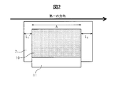
- the positive electrode area of the positive electrode active material layer of the positive electrode body or the negative electrode area of the negative electrode active material layer of the negative electrode body and the area of the separator are (separator area)> (electrode area ), And In an arbitrary straight line parallel to the first direction of the separator in a top view, the length of the portion where the electrode area and the separator overlap in the arbitrary straight line is A, and the electrode area and the separator overlap.
- L 1, L 1' the length of not is not part L 1, L 1 either shortest such optional straight line L 1 or L 1 'the following formula (1):
- X 1 (L 1 or L 1 ′ / (A / 2)) ⁇ 100 X 1 obtained by substituting In an arbitrary straight line parallel to the second direction of the separator in a top view, the length of the portion where the electrode area and the separator overlap on the arbitrary straight line is defined as B, and the electrode area and the separator overlap.
- the non-aqueous lithium storage element of the present invention can achieve both high energy density and durability while maintaining high output characteristics.
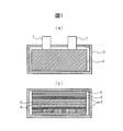
- (A) It is a cross-sectional schematic diagram of the plane direction which shows the one aspect
- (B) It is a cross-sectional schematic diagram of the thickness direction which shows the one aspect
- the negative electrode for a non-aqueous lithium storage element in the present invention has a negative electrode active material layer provided on a negative electrode current collector.
- Negative electrode active material The negative electrode active material in the present invention is contained in the negative electrode active material layer and satisfies the following 1) and 2) simultaneously: Tripolar cell in which LiPF 6 is dissolved at 1 mol / L in a solvent in which the working electrode is a negative electrode, the counter electrode is lithium, the reference electrode is lithium, and the electrolytic solution is a mixture of ethylene carbonate and methyl ethyl carbonate in a volume ratio of 1: 4.
- the current value is 100 mA / g per negative electrode active material and the cell temperature is 45 ° C., and is switched to a constant voltage when the negative electrode potential reaches 1 mV.
- the amount of charge after a total of 40 hours by constant current and constant voltage charge is the initial lithium charge amount, and after the above charge, the current value is 50 mA / g per negative electrode active material, and the cell temperature is When the discharge amount when lithium was discharged at a constant current until the negative electrode potential became 2.5 V under the condition of 45 ° C., the initial lithium discharge amount, In the initial lithium charge / discharge characteristics, 1) Charge amount is 1100 mAh / g or more and 2000 mAh / g or less; and 2) Discharge amount is 100 mAh / g or more at a negative electrode potential of 0 to 0.5V.
- the charge amount is 1100 mAh / g or more, the amount of the negative electrode active material in the negative electrode can be reduced, the negative electrode active material layer can be made thin, and the energy storage device can express a high energy density. If the charge amount is 2000 mAh / g or less, the amount of pores in the negative electrode active material does not increase excessively, and the bulk density of the negative electrode active material layer can be increased. Accordingly, the charge amount is preferably 1200 mAh / g or more and 1700 mAh / g or less, and more preferably, the charge amount is 1300 mAh / g or more and 1600 mAh / g or less.
- the discharge amount between the negative electrode potential of 0 to 0.5 V is preferably 120 mAh / g or more, and more preferably 140 mAh / g or more.
- the negative electrode active material in the present invention preferably contains a composite porous material in which pitch charcoal is deposited on the surface of activated carbon.
- the negative electrode active material containing the composite porous material of the present invention is characterized by satisfying the following i) and ii) simultaneously: i) The weight ratio of the pitch charcoal to the activated carbon is 10% or more and 60% or less, and the pitch softening point of the pitch charcoal is 100 ° C. or less; and ii) the negative electrode active material is BET
- the specific surface area is 350 m 2 / g to 1500 m 2 / g, and lithium ions are doped 1100 mAh / g to 2000 mAh / g per unit weight.
- the weight ratio of the pitch charcoal to the activated carbon is 10% or more, the micropores that the activated charcoal has can be appropriately filled with the pitch charcoal, and durability is improved by improving the charge / discharge efficiency of lithium ions. Will not be damaged.
- the weight ratio of the carbonaceous material is 60% or less, the specific surface area can be increased by appropriately holding the pores of the composite porous material, and the amount of lithium ion pre-doping can be increased. High output density and high durability can be maintained even if the temperature is increased. From the above, this weight ratio is preferably 15% or more and 55% or less, more preferably 18% or more and 50% or less, and particularly preferably 20% or more and 47% or less.
- the softening point of the pitch coal raw material is 100 ° C. or less, it is not bound by theory, but the micropores possessed by the activated carbon can be appropriately filled with the pitch coal.
- the pitch softening point is preferably 90 ° C. or less, and more preferably 50 ° C. or less.
- the pitch softening point is preferably about 35 ° C. or higher.
- the specific surface area of the negative electrode active material in the BET method is 350 m 2 / g or more, the pores of the negative electrode active material can be appropriately retained, and the doping amount of lithium ions can be increased. Can be realized.
- the specific surface area is 1500 m 2 / g or less, the micropores of the activated carbon can be appropriately filled, and the charge / discharge efficiency of the initial lithium charge / discharge characteristics is improved.
- the voltage is between 5V, the discharge amount can be increased, and the durability can be improved.
- the specific surface area is preferably 350 m 2 / g to 1100 m 2 / g, and more preferably 370 m 2 / g to 600 m 2 / g.
- the negative electrode active material is doped with lithium ions (also referred to as pre-doping).
- the pre-doping amount is 1100 mAh / g or more and 2000 mAh / g or less per unit weight of the composite porous material.
- This pre-doping amount is preferably 1200 mAh / g or more and 1700 mAh / g or less, and more preferably 1300 mAh / g or more and 1600 mAh / g or less.
- the pre-doping amount is 1100 mAh / g or more, lithium ions are sufficiently pre-doped at irreversible sites that cannot be desorbed once lithium ions in the negative electrode material are inserted.
- the amount of the negative electrode active material relative to the desired amount of lithium can be reduced, the negative electrode film thickness can be reduced, and high durability, output characteristics, and high energy density can be obtained.
- the higher the pre-doping amount the lower the negative electrode potential and the more the durability and energy density.
- the pre-doping amount is 2000 mAh / g or less, there is little risk of side effects such as precipitation of lithium metal.
- the negative electrode active material may be used alone or in combination of two or more.
- the composite porous material can be obtained, for example, by heat treatment in a state where activated carbon and pitch coexist.
- the activated carbon used as a raw material for the composite porous material is not particularly limited as long as the raw material before activated carbon is used as long as the obtained composite porous material exhibits desired characteristics. Commercial products obtained from various raw materials such as molecular systems can be used. It is preferable to use activated carbon powder having an average particle diameter of 1 ⁇ m to 15 ⁇ m. More preferably, the average particle size is 2 ⁇ m or more and 10 ⁇ m or less.
- the average particle size in the present invention is the particle size at which the cumulative curve becomes 50% when the cumulative curve is determined with the total volume being 100% when the particle size distribution is measured using a particle size distribution measuring device.
- % Diameter refers to the 50% diameter (Median diameter). This average particle diameter can be measured with a commercially available laser diffraction particle size distribution analyzer.
- the pitch used for the raw material of the composite porous material is roughly divided into petroleum pitch and coal pitch.
- petroleum pitches include crude oil distillation residue, fluid catalytic cracking residue (such as decant oil), bottom oil from thermal crackers, and ethylene tar obtained during naphtha cracking.
- the composite porous material is obtained by depositing pitch charcoal on the activated carbon by thermally reacting the volatile component or thermal decomposition component of the pitch on the surface of the activated carbon.
- the deposition of pitch volatile components or pyrolysis components into the activated carbon pores proceeds, and at 400 ° C. or higher, the reaction in which the deposited components become pitch charcoal proceeds.
- the peak temperature during the heat treatment is appropriately determined depending on the characteristics of the obtained composite porous material, the thermal reaction pattern, the thermal reaction atmosphere, and the like, but is preferably 400 ° C. or higher, more preferably 450 ° C. to 1000 ° C. ° C, more preferably about 500 to 800 ° C.
- the time for maintaining the peak temperature during the heat treatment may be 30 minutes to 10 hours, preferably 1 hour to 7 hours, and more preferably 2 hours to 5 hours.
- the pitch charcoal deposited on the activated carbon surface is considered to be a polycyclic aromatic hydrocarbon.
- Examples of the method for producing the composite porous material include a method in which activated carbon is heat-treated in an inert atmosphere containing hydrocarbon gas volatilized from pitch, and pitch charcoal is deposited in a gas phase. Moreover, the method of heat-mixing activated carbon and pitch previously, or the method of heat-processing after apply
- the composite porous material is obtained by depositing pitch charcoal on the surface of activated carbon, but the pore distribution after the pitch is deposited inside the pores of the activated carbon is important. Can be defined by quantity. That is, the composite porous material has a mesopore amount derived from pores having a diameter of 20 to 500 mm calculated by the BJH method as Vm1 (cc / g), and a micropore derived from pores having a diameter of less than 20 mm calculated by the MP method.
- the mesopore amount Vm1 is less than or equal to the upper limit (Vm1 ⁇ 0.300), the specific surface area of the composite porous material can be increased, the pre-doping amount of lithium ions can be increased, and the bulk density of the negative electrode As a result, the negative electrode can be thinned. Moreover, if the micropore amount Vm2 is not more than the upper limit value (Vm1 ⁇ 0.650), high charge / discharge efficiency with respect to lithium ions can be maintained. On the other hand, if the mesopore volume Vm1 and the micropore volume Vm2 are not less than the lower limit values (0.010 ⁇ Vm1, 0.010 ⁇ Vm2), high output characteristics can be obtained.
- the composite porous material preferably satisfies the above I) or II) among the above I) to III).
- the mesopore volume Vm1 is preferably 0.050 ⁇ Vm1 ⁇ 0.300.
- the amount of micropores and the amount of mesopores are values obtained by the following method. That is, the sample is vacuum-dried at 500 ° C. all day and night, and the adsorption and desorption isotherm is measured using nitrogen as an adsorbate. Using the isotherm on the desorption side at this time, the micropore volume was calculated by the MP method, and the mesopore volume was calculated by the BJH method.
- the MP method is a “t-plot method” (BC Lippens, JH de Boer, J. Catalysis, 4, 319 (1965)), which is used to calculate the micropore volume, the micropore area, and the micropore size. It means a method for obtaining the distribution of pores.
- the MP method is described in M.M. This is a method devised by Mikhal, Brunauer, Bodor (RS Mikhal, S. Brunauer, EE Bodor, J. Colloid Interface Sci., 26, 45 (1968)).
- the BJH method is a calculation method generally used for analyzing mesopores and proposed by Barrett, Joyner, Halenda et al. (E. P. Barrett, L. G. Joyner and P. Halenda). , J. Amer. Chem. Soc., 73, 373 (1951)).
- the amount of mesopores and the amount of micropores after depositing pitch charcoal on the surface of activated carbon is important, but composite porous materials having a pore distribution range defined in the present invention are used. In order to obtain, the pore distribution of the activated carbon used as a raw material is important.
- the activated carbon has a mesopore amount derived from pores having a diameter of 20 to 500 mm calculated by the BJH method as V1 (cc / g) and a micropore amount derived from pores having a diameter of less than 20 mm calculated by the MP method.
- V1 (cc / g) it is preferable that 0.050 ⁇ V1 ⁇ 0.500, 0.005 ⁇ V2 ⁇ 1.000, and 0.2 ⁇ V1 / V2 ⁇ 20.0.
- the mesopore amount 0.050 ⁇ V1 ⁇ 0.350 is more preferable, and 0.100 ⁇ V1 ⁇ 0.300 is still more preferable.
- the amount of micropores is more preferably 0.005 ⁇ V2 ⁇ 0.850, and further preferably 0.100 ⁇ V2 ⁇ 0.800.
- the ratio of mesopore amount / micropore amount is more preferably 0.22 ⁇ V1 / V2 ⁇ 10.0, and further preferably 0.25 ⁇ V1 / V2 ⁇ 10.0.
- the process for producing the composite porous material described above is less likely to occur after the pitch charcoal is deposited on the surface of the activated carbon, and the average particle diameter before and after the deposition is Characterized by almost no change.
- the amount of micropores and the amount of mesopores are reduced after deposition, as is clear from the characteristics of the above-mentioned process for producing the composite porous material and the examples described later. It can be presumed that most of the volatile component or pyrolysis component of the pitch is deposited in the pores of the activated carbon, and the reaction in which the deposited component becomes pitch charcoal has progressed.
- the average particle size of the composite porous material in the present invention is almost the same as that of the activated carbon before deposition, but is preferably 1 ⁇ m or more and 10 ⁇ m or less.
- a lower limit More preferably, it is 2 micrometers or more, More preferably, it is 2.5 micrometers or more.
- about an upper limit More preferably, it is 6 micrometers or less, More preferably, it is 4 micrometers or less. If the average particle diameter is 2 ⁇ m or more and 10 ⁇ m or less, sufficient durability is maintained.
- the measuring method of the average particle diameter of the composite porous material said here is the same method as the activated carbon used for the above-mentioned raw material.
- the average pore diameter is preferably 28 mm or more, more preferably 30 mm or more from the viewpoint of achieving high output characteristics.
- it is preferably 65 mm or less, and more preferably 60 kg or less.
- the average pore diameter is obtained by dividing the total pore volume per weight obtained by measuring each equilibrium adsorption amount of nitrogen gas at each relative pressure at the liquid nitrogen temperature by the BET specific surface area. Means something.
- the atomic ratio of hydrogen atoms / carbon atoms (hereinafter also referred to as H / C) is preferably 0.05 or more and 0.35 or less, and 0.05 or more and 0.15. The following is more preferable.
- H / C exceeds the upper limit, the carbonaceous material polycyclic aromatic conjugated structure deposited on the activated carbon surface is not sufficiently developed, so the capacity (energy density) and charge / discharge efficiency are low. Become.
- H / C is lower than the lower limit, carbonization may proceed excessively and a sufficient energy density may not be obtained.
- H / C is measured by an elemental analyzer.
- the composite porous material has an amorphous structure derived from the activated carbon as a raw material, but at the same time has a crystal structure mainly derived from the deposited carbonaceous material.
- the composite porous material has a (002) plane spacing d 002 of 3.60 to 4.00 and a c-axis direction crystal obtained from the half width of this peak.
- d 002 preferably has child size Lc is less 20.0 ⁇ than 8.0 ⁇
- d 002 is less 3.75 ⁇ than 3.60A
- a conductive filler and a binder can be added to the negative electrode active material layer as necessary.
- the type of the conductive filler is not particularly limited, and examples thereof include acetylene black, ketjen black, and vapor grown carbon fiber.
- the addition amount of the conductive filler is preferably 0 to 30% by mass with respect to the negative electrode active material, for example.
- the binder is not particularly limited, and PVDF (polyvinylidene fluoride), PTFE (polytetrafluoroethylene), styrene-butadiene copolymer, and the like can be used.
- the amount of the binder added is preferably in the range of 3 to 20% by mass with respect to the negative electrode active material, for example.
- a negative electrode for a non-aqueous lithium-type storage element can be manufactured by an electrode molding method such as a known lithium ion battery or an electric double layer capacitor.
- a negative electrode active material, a conductive filler, and a binder are used as a solvent. It is obtained by dispersing, forming a slurry, applying an active material layer on a current collector, drying, and pressing as necessary. In addition, it is possible to dry-mix without using a solvent and press-mold the active material, and then affix it to the current collector using a conductive adhesive or the like.
- the negative electrode for the non-aqueous lithium storage element may be one in which the negative electrode active material layer is formed only on one side of the current collector, or may be formed on both sides.
- the thickness of the negative electrode active material layer is 15 ⁇ m or more and 45 ⁇ m or less per side, preferably 20 ⁇ m or more and 40 ⁇ m or less. When the thickness is 15 ⁇ m or more, sufficient charge / discharge capacity can be exhibited. On the other hand, if this thickness is 45 ⁇ m or less, the energy density can be increased by reducing the cell volume.
- the thickness of the negative electrode active material layer means the average value of the thickness per side of the portion of the current collector that does not have holes.
- examples of the hole include a punching metal through-hole portion and an expanded metal opening portion.
- the bulk density of the negative electrode active material layer is preferably 0.60 g / cm 3 or more and 1.2 g / cm 3 or less, more preferably 0.70 g / cm 3 or more and 1.0 g / cm 3 or less.
- the bulk density is 0.60 g / cm 3 or more, sufficient strength can be maintained and sufficient conductivity between the active materials can be expressed.
- it is 1.2 g / cm ⁇ 3 > or less, the void
- the material of the negative electrode current collector is not particularly limited as long as it does not cause degradation such as elution and reaction when the storage element is formed, and examples thereof include copper, iron, and stainless steel.
- copper is preferably used as the negative electrode current collector.
- a metal foil or a structure in which an electrode can be formed in a gap between metals can be used, and the metal foil may be a normal metal foil having no through hole, expanded metal, punching metal Alternatively, a metal foil having a through hole such as an etching foil may be used.
- the thickness of the negative electrode current collector is not particularly limited as long as the shape or strength of the negative electrode can be sufficiently maintained, but is preferably 1 to 100 ⁇ m, for example.
- Pre-doping of lithium ions into the negative electrode active material A known method can be used as a method of pre-doping lithium ions into the negative electrode for a non-aqueous lithium storage element. For example, after forming a negative electrode active material into an electrode, using the negative electrode as a working electrode and metallic lithium as a counter electrode, an electrochemical cell combining non-aqueous electrolyte is prepared, and lithium ions are electrochemically pre-doped. A method is mentioned. It is also possible to pre-dope lithium ions into the negative electrode by pressing a metal lithium foil on the negative electrode and placing it in a non-aqueous electrolyte.
- a negative electrode active material obtained by depositing pitch charcoal on the surface of activated carbon includes a composite porous material. i) and ii): i) The weight ratio of the pitch charcoal to the activated carbon is 10% or more and 60% or less, and the pitch softening point of the pitch charcoal is 100 ° C. or less; and ii) the negative electrode active material is BET Specific surface area is 350 m 2 / g to 1500 m 2 / g and lithium ions are doped 1100 mAh / g to 2000 mAh / g per unit weight; It is preferable to satisfy.
- the thickness of the negative electrode active material layer is adjusted to 15 ⁇ m or more and 45 ⁇ m or less, and pitch charcoal / It is preferable to adjust the activated carbon (weight ratio) and the pitch softening point within a range in which the durability of the negative electrode is not impaired and the pre-doping amount of lithium ions can be increased.
- the positive electrode for a non-aqueous lithium storage element in the present invention has a positive electrode active material layer provided on a positive electrode current collector.
- the positive electrode active material layer contains a positive electrode active material and a binder, and optionally contains a conductive filler.
- the positive electrode active material the following activated carbon 1 or activated carbon 2 is preferably used.
- the type of activated carbon 1 and its raw material are not particularly limited, but in order to achieve both high capacity (that is, high energy density) and high output characteristics (that is, high output density), the pores of activated carbon should be optimally controlled. Is preferred. Specifically, the amount of mesopores derived from pores having a diameter of 20 to 500 mm calculated by the BJH method is V1 (cc / g), and the amount of micropores derived from pores having a diameter of less than 20 mm calculated by the MP method is calculated.
- V2 (cc / g) When V2 (cc / g) is satisfied, 0.3 ⁇ V1 ⁇ 0.8 and 0.5 ⁇ V2 ⁇ 1.0 are satisfied, and the specific surface area measured by the BET method is 1500 m 2 / g or more and 3000 m 2. Activated carbon that is less than / g is preferred.
- the mesopore amount V1 is preferably a value larger than 0.3 cc / g from the viewpoint of increasing the output characteristics when the positive electrode material is incorporated in the power storage element, and also from the viewpoint of suppressing a decrease in the capacity of the power storage element. , Preferably 0.8 cc / g or less. V1 is more preferably 0.35 cc / g or more and 0.7 cc / g or less, and further preferably 0.4 cc / g or more and 0.6 cc / g or less.
- the micropore volume V2 is preferably 0.5 cc / g or more in order to increase the specific surface area of the activated carbon 1 and increase the capacity, and also suppresses the bulk of the activated carbon 1 and reduces the density as an electrode. From the viewpoint of increasing the capacity per unit volume, it is preferably 1.0 cc / g or less.
- the V2 is more preferably 0.6 cc / g or more and 1.0 cc / g or less, and further preferably 0.8 cc / g or more and 1.0 cc / g or less.
- the ratio of the mesopore volume V1 to the micropore volume V2 is preferably in the range of 0.3 ⁇ V1 / V2 ⁇ 0.9. That is, V1 / V2 is preferably 0.3 or more from the viewpoint of increasing the ratio of the mesopore amount to the micropore amount to such an extent that the decrease in output characteristics can be suppressed while obtaining a high capacity. V1 / V2 is preferably 0.9 or less from the viewpoint of increasing the ratio of the micropore amount to the mesopore amount so that the decrease in capacity can be suppressed while obtaining high output characteristics. A more preferable range of V1 / V2 is 0.4 ⁇ V1 / V2 ⁇ 0.7, and a more preferable range of V1 / V2 is 0.55 ⁇ V1 / V2 ⁇ 0.7.
- micropore amount and mesopore amount of the activated carbon 1 are values obtained by the same method as that for the composite porous material described above.
- the average pore diameter of the activated carbon 1 is preferably 17 mm or more, more preferably 18 mm or more, and most preferably 20 mm or more in order to maximize the output. Further, from the point of maximizing the capacity, it is preferably 25 mm or less.
- the average pore diameter described in the present specification is obtained by dividing the total pore volume per weight obtained by measuring each equilibrium adsorption amount of nitrogen gas at each relative pressure at the liquid nitrogen temperature by the BET specific surface area. Point to what you asked for.
- BET specific surface area of the activated carbon 1 is preferably from 1500 m 2 / g or more 3000 m 2 / g, more preferably not more than 1500 m 2 / g or more 2500 m 2 / g.
- the BET specific surface area is 1500 m 2 / g or more, good energy density is easily obtained.
- the BET specific surface area is 3000 m 2 / g or less, a large amount of binder is used to maintain the strength of the electrode. Since it is not necessary to put in, the performance per electrode volume tends to be high.
- the activated carbon 1 having the above-described characteristics can be obtained using, for example, raw materials and processing methods as described below.
- the carbon source used as a raw material of the activated carbon 1 is not particularly limited, and for example, plant systems such as wood, wood flour, coconut shell, by-products during pulp production, bagasse, and molasses.
- Raw materials Fossil materials such as peat, lignite, lignite, bituminous coal, anthracite, petroleum distillation residue components, petroleum pitch, coke, coal tar; phenol resin, vinyl chloride resin, vinyl acetate resin, melamine resin, urea resin, resorcinol resin, Various synthetic resins such as celluloid, epoxy resin, polyurethane resin, polyester resin, and polyamide resin; synthetic rubbers such as polybutylene, polybutadiene, and polychloroprene; other synthetic wood, synthetic pulp, and their carbides.
- plant-based raw materials such as coconut shells and wood flour, and carbides thereof are preferable, and coconut shell carbides are particularly preferable.
- the carbonization and activation methods for using these raw materials as the activated carbon known methods such as a fixed bed method, a moving bed method, a fluidized bed method, a slurry method, and a rotary kiln method can be employed.
- an exhaust gas such as combustion exhaust gas, or other gases mainly composed of these inert gases. Examples of the method include firing at a temperature of about 400 to 700 ° C. (preferably 450 to 600 ° C.) for about 30 minutes to 10 hours using a mixed gas.
- a gas activation method in which firing is performed using an activation gas such as water vapor, carbon dioxide, or oxygen is preferably used.
- an activation gas such as water vapor, carbon dioxide, or oxygen
- a method using water vapor or carbon dioxide as the activation gas is preferable.
- the carbide is supplied for 3 to 12 hours (preferably 5 to 11) while supplying an activation gas at a rate of 0.5 to 3.0 kg / h (preferably 0.7 to 2.0 kg / h). It is preferable to activate by heating to 800 to 1000 ° C. over a period of time, more preferably 6 to 10 hours.
- the carbide may be activated in advance prior to the activation treatment of the carbide.
- the carbide may be activated in advance.
- an activation gas such as water vapor, carbon dioxide or oxygen.
- Activated carbon 1 having the above-described characteristics that can be used in the embodiment of the present invention by appropriately combining the firing temperature and firing time in the carbonization method, the activated gas supply amount, the heating rate and the maximum activation temperature in the activation method. Can be manufactured.
- the average particle diameter of the activated carbon 1 is preferably 1 to 20 ⁇ m.
- the average particle size described in the present specification is the particle at which the cumulative curve becomes 50% when the cumulative curve is determined with the total volume being 100% when the particle size distribution is measured using a particle size distribution measuring device. Diameter (ie 50% diameter (Median diameter)).
- the average particle diameter When the average particle diameter is 1 ⁇ m or more, the capacity per electrode volume tends to increase because the density of the active material layer is high. On the other hand, when the average particle size is 20 ⁇ m or less, it tends to be suitable for high-speed charge / discharge. Further, the average particle diameter is preferably 2 to 15 ⁇ m, more preferably 3 to 10 ⁇ m.
- the positive electrode active material has a mesopore amount derived from pores having a diameter of 20 to 500 mm calculated by the BJH method as V1 (cc / g) and a micropore amount derived from pores having a diameter of less than 20 mm calculated by the MP method.
- V2 (cc / g) it is preferable to include activated carbon 2 that satisfies 0.8 ⁇ V1 ⁇ 2.5 and 0.92 ⁇ V2 ⁇ 3.0.
- the mesopore amount V1 is preferably a value larger than 0.8 cc / g from the viewpoint of increasing the output characteristics when the positive electrode material is incorporated in the power storage element, and from the viewpoint of suppressing a decrease in the capacity of the power storage element. It is preferable that it is 2.5 cc / g or less. V1 is more preferably 1.00 cc / g or more and 2.0 cc / g or less, and further preferably 1.2 cc / g or more and 1.8 cc / g or less.
- the micropore volume V2 is preferably larger than 0.92 cc / g in order to increase the specific surface area of the activated carbon 2 and increase the capacity, and also increases the density of the activated carbon 2 as an electrode. From the viewpoint of increasing the capacity per unit volume, it is preferably 3.0 cc / g or less. V2 is more preferably greater than 1.0 cc / g and not greater than 2.5 cc / g, and still more preferably not less than 1.5 cc / g and not greater than 2.5 cc / g.
- the activated carbon 2 having the mesopore amount and the micropore amount described above has a higher BET specific surface area than activated carbon used for conventional electric double layer capacitors or lithium ion capacitors.
- Specific values of the BET specific surface area are 2600 m 2 / g or more and 4500 m 2 / g or less, and preferably 3000 m 2 / g or more and 4000 m 2 / g or less.
- the BET specific surface area is 2600 m 2 / g or more, good energy density is easily obtained.
- the BET specific surface area is 4500 m 2 / g or less, a large amount of binder is used to maintain the strength of the electrode. Since it is not necessary to put in, there exists a tendency for the performance per electrode volume to become high.
- the activated carbon 2 having the above-described characteristics can be obtained using, for example, the raw materials and processing methods described below.
- the carbonaceous material used as a raw material for the activated carbon 2 is not particularly limited as long as it is a carbon source that is usually used as a raw material for activated carbon.
- plant-based raw materials such as wood, wood flour, and coconut shells
- fossil raw materials such as coke
- various synthetic resins such as phenol resin, furan resin, vinyl chloride resin, vinyl acetate resin, melamine resin, urea resin, and resorcinol resin.
- phenol resin and furan resin are particularly preferable because they are suitable for producing activated carbon 2 having a high specific surface area.
- Examples of a method for carbonizing these raw materials or a heating method at the activation treatment include known methods such as a fixed bed method, a moving bed method, a fluidized bed method, a slurry method, and a rotary kiln method.
- the atmosphere at the time of heating is an inert gas such as nitrogen, carbon dioxide, helium, or argon, or a gas mixed with other gases containing these inert gases as a main component.
- the carbonization temperature is about 400 to 700 ° C.
- the firing is performed for about 0.5 to 10 hours.
- the pulverization method may be either dry pulverization or wet pulverization, but wet pulverization is preferable from the viewpoint of pulverization speed, continuous operability and power consumption.
- wet pulverization specifically, the following conditions can be employed.
- a sample to be crushed, hard beads such as metal, zirconia and ceramic, and a solvent are put into a hard container such as metal, agate or ceramic, and pulverized. It is preferable that the container can be sealed, and it is preferable to replace the inside of the container with an inert gas such as nitrogen or argon during pulverization.
- the solvent water or an organic solvent can be used, but an organic solvent having a low boiling point is not suitable because there is a risk of ignition.
- the pulverization time is adjusted according to the particle size of the obtained material, the pulverization for a long time may cause impurities to be mixed. Since the particle size distribution is broadened by pulverization, classification with a sieve is preferable. As a result of classification, in the present invention, classification can be performed between 1 ⁇ m and 30 ⁇ m.
- the carbonaceous material obtained in the above pulverization / classification step is carbonized into a carbide by the following method.
- a gas activation method in which firing is performed using an activation gas such as water vapor, carbon dioxide, oxygen, or an alkali metal activation method in which heat treatment is performed after mixing with an alkali metal compound.
- An alkali metal activation method is preferable for producing activated carbon having a high specific surface area.
- the carbide and the alkali metal compound such as KOH and NaOH are mixed so that the weight ratio is 1: 1 or more, and then in the range of 600 to 900 ° C. in an inert gas atmosphere, 0.5 to Heating is performed for 5 hours, and then the alkali metal compound is removed by washing with an acid and water, followed by drying.
- a larger amount of carbide is mixed with KOH when activated.
- KOH is increased with respect to the ratio of carbide to KOH.
- water vapor activation is performed after alkali activation treatment.
- the average particle diameter of the activated carbon 2 used for the non-aqueous lithium storage element of the present invention is 1 ⁇ m or more and 30 ⁇ m or less, preferably 2 ⁇ m or more and 20 ⁇ m or less. More preferably, it is 2 ⁇ m or more and 7 ⁇ m or less.
- a mixture of two kinds of activated carbons having different average particle sizes may be used.
- the average particle diameter is 50% when the particle size distribution is measured using a particle size distribution measuring device, and when the cumulative curve is determined with the total volume being 100%, the cumulative curve is 50%.
- the diameter refers to the 50% diameter (Median diameter).
- the positive electrode active material contains a material other than activated carbon having the specific V1 and V2 (for example, activated carbon not having the specific V1 and V2, a composite oxide of lithium and a transition metal), the specific The content of the activated carbon having V1 and V2 is more than 50% by weight of the total positive electrode active material.
- the content of the activated carbon having the specific V1 and V2 in the total positive electrode active material is more preferably 70% by weight or more, further preferably 90% by weight or more, and most preferably 100% by weight.
- the positive electrode may have a positive electrode active material layer formed on only one side of the positive electrode current collector or may be formed on both sides.
- the thickness of the positive electrode active material layer is preferably, for example, 30 ⁇ m to 200 ⁇ m per side.
- the material of the positive electrode current collector is not particularly limited as long as it is a conductive material that does not cause elution into the electrolytic solution or deterioration such as reaction when it is used as a storage element.
- a suitable material is aluminum.
- As the shape of the positive electrode current collector a metal foil or a structure (such as a foam) in which an electrode can be formed in a gap between metals can be used.
- the metal foil may be a normal metal foil having no through hole, or a metal foil having a through hole such as an expanded metal or a punching metal.
- the thickness of the positive electrode current collector is not particularly limited as long as the shape and strength of the electrode can be sufficiently maintained, but for example, 1-100 ⁇ m is preferable from the viewpoint of strength, conductive resistance, and capacity per volume.
- the binder used for the positive electrode active material layer is not particularly limited, and PVDF (polyvinylidene fluoride), PTFE (polytetrafluoroethylene), styrene-butadiene copolymer, and the like can be used.
- the binder content in the positive electrode active material layer is preferably in the range of 3 to 20 parts by mass with respect to 100 parts by mass of the positive electrode active material.
- an electroconductive filler can be added to a positive electrode active material layer as needed.
- the type of the conductive filler is not particularly limited, and examples thereof include acetylene black, ketjen black, and vapor grown carbon fiber.
- the addition amount of the conductive filler is preferably 0 to 30 parts by mass with respect to 100 parts by mass of the active material, for example.
- the positive electrode can be manufactured using a known electrode forming technique such as a lithium ion battery or an electric double layer capacitor.
- a slurry in which a positive electrode active material, a conductive filler, and a binder are dispersed in a solvent The positive electrode active material layer can be obtained by performing a coating process on the positive electrode current collector, a drying process for drying the solvent, and a pressurizing process for improving the bulk density of the positive electrode active material layer by pressurization.
- the bulk density of the positive electrode active material layer is 0.40 g / cm 3 or more, preferably 0.45 g / cm 3 or more and 0.70 g / cm 3 or less.
- the bulk density is 0.40 g / cm 3 or more, the capacity of the electrode per volume can be increased, and the storage element can be reduced in size.
- the bulk density is 0.70 g / cm 3 or less, it is considered that the electrolyte solution is sufficiently diffused in the voids in the positive electrode active material layer and the charge / discharge characteristics at a large current are high.
- the bulk density of the positive electrode active material layer used in one embodiment of the present invention is due to the fact that it has a specific amount of micropores and mesopores, so that the bulk of a normal activated carbon active material layer produced by the same method is used. Small compared to density.
- a method of applying pressure hereinafter also referred to as “heating press”.
- a molding process in which activated carbon and a binder are mixed by a dry method without using a solvent, and are pressed into a plate shape while being heated to a temperature of the melting point of the binder minus 40 ° C. or higher and lower than the melting point, and The bonding step of attaching the formed positive electrode active material layer to the positive electrode current collector with a conductive adhesive may be performed.
- fusing point can be calculated
- sample resin is set in a measurement cell, and the temperature is increased from 30 ° C. to 250 ° C. at a temperature increase rate of 10 ° C./min in a nitrogen gas atmosphere. The temperature is raised, and the endothermic peak temperature in the temperature raising process becomes the melting point.
- DSC7 differential scanning calorimeter
- the hot press method can be performed, for example, in the following steps.
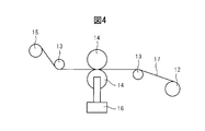
- the equipment used for the heating press will be described with reference to FIG.
- coated the positive electrode active material layer to the positive electrode electrical power collector is wound up, and it installs in an unwinding roll position.
- the positive electrode (17) is wound around a winding roll (15) through a first guide (13), a heated press roll (14), and a second guide (13) in this order.
- the surface temperature of the heated press roll (14) is set to a temperature not lower than the melting point of the binder contained in the positive electrode active material layer minus 40 ° C. and not higher than the melting point, preferably not lower than the melting point minus 30 ° C. and lower than the melting point, more preferably. It selects from the temperature below melting
- PVDF polyvinylidene fluoride: melting point 150 ° C.
- it is preferably heated within a range of 110 to 150 ° C., more preferably within a range of 120 to 150 ° C.
- styrene-butadiene copolymer (melting point 100 ° C.)
- it is preferably heated in the range of 60 to 100 ° C., more preferably in the range of 70 to 100 ° C.
- the pressurizing pressure at the time of hot pressing and the pressing speed are adjusted by the bulk density of the positive electrode to be obtained.
- the press pressure of the heating press roll is kept constant by adjusting the pressure of the hydraulic cylinder (16).
- the pressing pressure is preferably 50 kgf / cm or more and 300 kgf / cm or less.
- the pressing speed is preferably 15 m / min or less, more preferably 10 m / min or less, and still more preferably 5 m / min or less. A sufficient bulk density can be obtained at the above pressing speed.
- the active material layer is peeled off from the current collector, and therefore it is preferable to determine the pressing pressure by measuring the resistance of the cell, the discharge capacity retention rate, and the like.
- the distance between press rolls can be arbitrarily selected.
- pressing is performed at a distance between the rolls that is at least narrower than the electrode thickness to be pressed, but the effect of increasing the bulk density by the press is small at the distance between the rolls that is closer to the electrode thickness.
- the positive electrode of the present invention is preferably pressed twice or more.
- a single press cannot increase the bulk density sufficiently, or in order to increase the bulk density, it is necessary to press at a press pressure that is too high or a distance between rolls that is too narrow, resulting in peeling and cell resistance. And the performance such as the discharge capacity maintenance rate is reduced. If the positive electrode is significantly damaged, the cell may not be produced.
- the distance between the rolls is equal to the distance between the rolls during the second press, more preferably narrower than that during the first press.
- the first roll distance is 1
- the second roll distance is 0.4 to 0.6
- the third roll is performed
- the second roll distance is 1.
- the required bulk density can be obtained.
- the press pressure may be the same or higher during the second press compared to the first press.
- a higher pressing pressure is preferable for improving the density.
- the heating press roll (14) is rotated in the direction in which the positive electrode (17) is sent from the unwinding roll (12) to the winding roll (15), and controlled to an arbitrary speed.
- the winding roll (15) rotates so that the tension of the electrode becomes an appropriate value and winds up the positive electrode (17).
- the unwinding roll (12) does not need to rotate, but is preferably a load that gives a tension that does not sag the positive electrode (17).
- the electricity storage device of the present invention includes a positive electrode and a negative electrode molded as described above, and an electrode body in which separators are laminated or spirally laminated, a non-aqueous electrolyte, and a metal can or a laminate film. including.
- the separator used in the capacitor of the present invention insulates the positive electrode body and the negative electrode body from being in direct electrical contact with each other, and holds the electrolytic solution in the internal gap to provide a lithium ion conduction path between the electrodes. Play a role to form.
- a separator consists of polyolefin resin containing polyethylene.
- the thermal contraction rate of the separator when the separator is kept at 100 ° C. for 1 hour in an unconstrained state, the thermal contraction rate of the separator is 3% or more and 10% or less in the first direction, and the first In the second direction orthogonal to the direction, the range is 2% or more and 10% or less.
- the thermal contraction rate of the separator is more preferably 4% or more and 9% or less in the first direction, 3% or more and 9% or less in the second direction, and further preferably 5% in the first direction. It is 8% or less, and is 3.5% or more and 5% or less in the second direction.
- the first direction is the MD direction (the advancing direction when the sheet-formed separator is wound on a roll, also referred to as “longitudinal direction”)
- the second direction is the TD direction (perpendicular to the MD direction).
- Direction also referred to as “width direction” or “short direction”
- the first direction is MD
- the second direction is May be written as TD.
- the “unconstrained state” means a state in which the object is not fixed, and means, for example, that a sheet-like separator is put in an oven as it is. This heat shrinkage rate is measured according to the method described in the following examples.
- the larger electrode area of the positive electrode area of the positive electrode active material layer of the positive electrode body of the present invention or the negative electrode area of the negative electrode active material layer of the negative electrode body and the area of the separator is (separator area)>
- the length of the portion where the electrode area and the separator overlap in any straight line in an arbitrary straight line that is (electrode area) and parallel to the first direction of the separator in a top view is A.
- A, L 1 and L 1 ′ for obtaining X 1 will be described.
- 7 is a separator
- 10 is the positive electrode area of the positive electrode active material layer of the positive electrode body or the negative electrode area of the negative electrode active material layer of the negative electrode body
- 11 is the electrode (10 ) Shows the current collector (portion where the active material layer is not applied). The same is true for X 2.
- X 1 and X 2 are preferably 2.0 or more and 6.0 or less, and more preferably 3.0 or more and 5.0 or less.
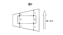
- FIG. 3 explains the concept of “margin” in the present invention.
- the margin was defined by the ratio of the width (L 1 , L 2 , L 3 , L 4 ) of the separator protruding from the electrode and the electrode width (A 1 , A 2 ).
- the margin part (L 1 ) with the shortest width shrinks to the inside of the electrode by heating the fastest and causes a short circuit. (L 1 ⁇ L 3 ⁇ L 2 ⁇ L 4 ). Accordingly, the margin portion (L 1 ) having the shortest width is determined as a specific method corresponding to various shapes.
- the separator has an MD direction and a TD direction in production, and the flowed product is also decomposed and heated, and the direction can be specified from the heat-shrinkable state. Therefore, the MD direction and the TD direction are specified.
- rupture refers to a state in which the electrode laminate is broken and scattered with the electrolyte when the outer package is opened.
- a separator made of a polyolefin resin containing polyethylene having a heat shrinkage rate as described above is melted down in a short time at an abnormally high temperature, and when the exterior body is opened due to the continuation of the abnormally high temperature state, It has been found preferable because the capacitor can be safely short-circuited without ignition and the safety can be improved.
- the thermal contraction rate of the separator of the present invention is 3% or more in the first direction and 2% or more in the second direction, the separator can be melted down at an abnormally high temperature in a short period of time, resulting in rupture or ignition.
- Capacitor can be safely short-circuited without the need to improve safety, and if the first direction is 10% or less and the second direction is 10% or less, the capacitor function is maintained without being short-circuited in the normal operating temperature range. can do.
- the capacitor function can be maintained without being short-circuited in the normal operating temperature range, and if it is 8.0% or less, it is short at an abnormally high temperature. It can be melted down in time, and the capacitor can be safely short-circuited without rupture or ignition, improving safety.
- the separator is preferably a microporous membrane
- the puncture strength (absolute strength) of the microporous membrane is preferably 200 g or more, and more preferably 300 g or more.
- the piercing strength is 200 g or more
- a microporous film is used as a capacitor separator, pinholes or cracks may occur even when sharp parts such as electrode materials provided in the capacitor pierce the microporous film. It is preferable from the viewpoint that generation can be reduced.
- limiting in particular as an upper limit of puncture strength It is preferable that it is 1000 g or less.
- the puncture strength is measured according to the method described in the examples below.
- the porosity of the microporous membrane of the present embodiment is preferably 30% to 70%, more preferably 55 to 70%. Setting the porosity to 30% or more is preferable from the viewpoint of following the rapid movement of lithium ions at a high rate when a microporous film is used as a capacitor separator. On the other hand, setting the porosity to 70% or less is preferable from the viewpoint of improving the film strength, and also preferable from the viewpoint of suppressing self-discharge when the microporous film is used as a capacitor separator.
- the AC resistance of the microporous membrane of this embodiment preferably 0.9 ⁇ ⁇ cm 2 or less from the output when used as a separator for capacitors, and more preferably 0.6 ohm ⁇ cm 2 or less, 0.3 [Omega -More preferably cm 2 or less.
- Electrode terminal and connection to the electrode body In the electrode body, one end of the positive electrode terminal is electrically connected to the positive electrode, and one end of the negative electrode terminal is electrically connected to the negative electrode. Specifically, the positive electrode terminal is electrically connected to the positive electrode active material layer uncoated region of the positive electrode current collector, and the negative electrode terminal is electrically connected to the negative electrode active material layer uncoated region of the negative electrode current collector. It is preferable that the material of the positive electrode terminal is aluminum and the material of the negative electrode terminal is copper plated with nickel.
- An electrode terminal (collectively referred to as a positive electrode terminal and a negative electrode terminal) generally has a substantially rectangular shape, one end of which is electrically connected to an electrode current collector, and the other end is externally connected during use. It is electrically connected to a load (when discharging) or a power source (when charging).
- the center part of the electrode terminal which becomes the sealing part of the laminate film outer package, is made of a resin such as polypropylene to prevent short circuit between the electrode terminal and the metal foil constituting the laminate film and to improve the sealing hermeticity. It is a preferable aspect that the film is affixed.
- the electrical connection method between the electrode body and the electrode terminal described above is, for example, generally an ultrasonic welding method, but may be resistance welding, laser welding, or the like, and is not limited.
- the laminate film used for the exterior body is preferably a film in which a metal foil and a resin film are laminated, and an example of a three-layer structure comprising an outer layer resin film / metal foil / interior resin film is exemplified.
- the outer layer resin film is for preventing the metal foil from being damaged by contact or the like.
- a resin such as nylon or polyester can be suitably used.
- the metal foil is for preventing the permeation of moisture or gas, and copper, aluminum, stainless steel and other foils can be suitably used as the metal foil.
- the interior resin film protects the metal foil from the electrolyte contained therein and melts and seals it at the time of heat sealing, and polyolefin and acid-modified polyolefin can be preferably used.
- the non-aqueous electrolyte solution used for the electricity storage device of the present invention may be any non-aqueous liquid containing a lithium ion-containing electrolyte.
- a non-aqueous liquid may contain an organic solvent, and examples of such an organic solvent include ethylene carbonate (EC), cyclic carbonate represented by propylene carbonate (PC), diethyl carbonate (DEC), A chain carbonate represented by dimethyl carbonate (DMC), ethyl methyl carbonate (MEC), lactones such as ⁇ -butyrolactone ( ⁇ BL), and a mixed solvent thereof can be used.
- lithium salts such as LiBF 4 and LiPF 6 can be used as a salt dissolved in these non-aqueous liquids.
- the salt concentration of the electrolytic solution is preferably in the range of 0.5 to 2.0 mol / L. At 0.5 mol / L or more, sufficient anions are present, and the capacity of the electricity storage device is maintained. On the other hand, at 2.0 mol / L or less, the salt is sufficiently dissolved in the electrolytic solution, and appropriate viscosity and conductivity of the electrolytic solution are maintained.
- the positive electrode and the negative electrode are inserted into an exterior body formed from a metal can or a laminate film as an electrode body laminated or wound around via a separator.
- FIGS. 1A and 1B One embodiment of the non-aqueous lithium storage element of this embodiment is represented by the schematic cross-sectional views of FIGS. 1A and 1B.
- the positive electrode terminal (1) and the negative electrode terminal (2) This is a mode derived from one side of the electrode body (4).
- a mode in which the positive electrode terminal (1) and the negative electrode terminal (2) are led out from two opposing sides of the electrode body (4) can be mentioned.
- the latter embodiment is suitable for applications in which a larger current flows because the electrode terminals can be made wider.
- the storage element includes a positive electrode in which a positive electrode active material layer (6) is stacked on a positive electrode current collector (5), and a negative electrode in which a negative electrode active material layer (9) is stacked on a negative electrode current collector (8).
- (6) and the negative electrode active material layer (9) are alternately laminated so as to face each other with the separator (7) interposed therebetween to form the electrode body (4), and the positive electrode terminal (1) is connected to the positive electrode current collector ( 5), the negative electrode terminal (2) is connected to the negative electrode current collector (8), the electrode body (4) is housed in the exterior body (3), and the non-aqueous electrolyte (not shown) is exteriorized. It is injected into the body (3), and the outer peripheral body (3) is sealed in a state where the ends of the positive terminal (1) and the negative terminal (2) are pulled out of the outer body (3). .
- the maximum rated voltage is set within a range of 3.8 to 4.0 V, for example, because the higher one has a higher capacity in a range where overcharge is not caused.
- the minimum rated voltage is set within a range of 2.0 to 2.3 V, for example, because the lower one has a higher capacity in a range where overdischarge is not caused.
- the storage element immediately after the above assembly shows a voltage of about 3 V due to pre-doping of lithium ions into the negative electrode, it is preferably used after being charged as necessary.
- the amount of the pre-doped lithium ion that is changed by being doped or undoped by charging / discharging within the range of 2 to 4 V is about ⁇ 100 mAh / g. Therefore, when the pre-doping amount of lithium ions in the unit weight of the negative electrode active material is in the range of 1100 to 2000 mAh / g, the negative electrode active material in the negative electrode active material after being charged and discharged so as to have a potential in the range of 2 to 4 V.
- the doping amount of lithium ions is in the range of 1000 to 2100 mAh / g.
- Example 1 (Preparation of negative electrode) The pore distribution of a commercially available coconut shell activated carbon was measured using a pore distribution measuring device (AUTOSORB-1 AS-1-MP) manufactured by Yuasa Ionics, using nitrogen as an adsorbate. The specific surface area was determined by the BET single point method. Further, as described above, using the isotherm on the desorption side, the mesopore amount was determined by the BJH method, and the micropore amount was determined by the MP method.
- AUTOSORB-1 AS-1-MP pore distribution measuring device manufactured by Yuasa Ionics
- the BET specific surface area was 1,780 m 2 / g
- the mesopore volume (V1) was 0.198 cc / g
- the micropore volume (V2) was 0.695 cc / g
- V1 / V2 0.29
- the average fineness was 21.2 mm.
- 150 g of this activated carbon is put in a stainless steel mesh jar, placed on a stainless steel bat containing 75 g of coal-based pitch (softening point: 80 ° C.), and placed in an electric furnace tub (effective size in furnace 300 mm ⁇ 300 mm ⁇ 300 mm). It was installed and a thermal reaction was performed. The heat treatment was performed in a nitrogen atmosphere in 2 hours up to 680 ° C., held at the same temperature for 4 hours, then cooled to 60 ° C. by natural cooling, and then taken out from the furnace to be a composite porous material 1 serving as a negative electrode material Got.
- the weight ratio of the deposited carbonaceous material (hereinafter also referred to as “pitch charcoal”) to the activated carbon is 20%
- the BET specific surface area is 958 m 2 / g
- the mesopore amount (Vm1) is 0. .153 cc / g
- micropore volume (Vm2) was 0.381 cc / g.
- the average particle diameter was measured using a laser diffraction particle size distribution analyzer (SALD-2000J) manufactured by Shimadzu Corporation. As a result, it was 3.01 ⁇ m.
- the composite porous material 1 obtained above 83.4 parts by weight of the composite porous material 1 obtained above, 8.3 parts by weight of acetylene black, 8.3 parts by weight of PVDF (polyvinylidene fluoride) and NMP (N-methylpyrrolidone) were mixed. To obtain a slurry. Next, the obtained slurry was applied to one side of a 15 ⁇ m thick copper foil, dried, and pressed to obtain a negative electrode having a negative electrode active material layer thickness of 30 ⁇ m. The thickness of the negative electrode active material layer is determined by calculating the thickness of the copper foil from the average value of the thickness of the negative electrode measured at 10 locations on the negative electrode using a thickness gauge (Linear Gauge Sensor GS-551) manufactured by Ono Keiki Co., Ltd. The value obtained by subtraction.
- a thickness gauge Linear Gauge Sensor GS-551 manufactured by Ono Keiki Co., Ltd. The value obtained by subtraction.
- the negative electrode obtained above was cut out to 3 cm 2 , and the working electrode was a negative electrode, the counter electrode was lithium, the reference electrode was lithium, the electrolyte was 1 mol in a solvent in which ethylene carbonate and methyl ethyl carbonate were mixed at a volume ratio of 1: 4.
- the current value is 100 mA / g per negative electrode active material and the cell temperature is 45 ° C.
- the pore distribution of this activated carbon was measured with a pore distribution measuring device (AUTOSORB-1 AS-1-MP) manufactured by Yuasa Ionics.
- AUTOSORB-1 AS-1-MP pore distribution measuring device manufactured by Yuasa Ionics.
- the BET specific surface area was 2360 m 2 / g
- the mesopore volume (V1) was 0.52 cc / g
- the micropore volume (V2) was 0.88 cc / g
- V1 / V2 0.59
- the average pore diameter was It was 22.9 kg.
- activated carbon As a positive electrode active material, 83.4 parts by weight of activated carbon, 8.3 parts by weight of acetylene black, 8.3 parts by weight of PVDF (polyvinylidene fluoride) and NMP (N-methylpyrrolidone) are mixed, Obtained. Next, the obtained slurry was applied to one side of an aluminum foil having a thickness of 15 ⁇ m, dried and pressed to obtain a positive electrode having a positive electrode active material layer thickness of 60 ⁇ m.
- PVDF polyvinylidene fluoride
- NMP N-methylpyrrolidone
- the positive electrode obtained above was cut out to 2.5 cm 2 , and this positive electrode and the negative electrode pre-doped with the above lithium ions were opposed to each other with a cellulose paper separator having a thickness of 30 ⁇ m interposed therebetween, and a laminate using polypropylene and aluminum.
- a non-aqueous lithium storage element was assembled by enclosing it in a film exterior.
- a solution in which LiPF 6 was dissolved to a concentration of 1 mol / l in a solvent in which ethylene carbonate and methyl ethyl carbonate were mixed at a volume ratio of 1: 4 was used as an electrolytic solution.
- the produced power storage element was charged to 4.0 V with a current of 1 mA, and then a constant current and constant voltage charge for applying a constant voltage of 4.0 V was performed for 2 hours. went. Subsequently, the battery was discharged to 2.0 V with a constant current of 1 mA. The discharge capacity was 0.423 mAh. Next, when the same charge was performed and the battery was discharged to 2.0 V at 250 mA, a capacity of 0.297 mAh was obtained. That is, the ratio of the discharge capacity at 250 mA to the discharge capacity at 1 mA was 70.2%. Moreover, the discharge capacity per unit volume of the negative electrode active material layer was 47 mAh / cm 3 .
- the capacity retention rate was measured at the start of the test (0 h) and after 1,000 h had elapsed.
- the capacity maintenance rate here is a numerical value represented by ⁇ (discharge capacity after elapse of 1,000 h) / (discharge capacity at 0 h) ⁇ ⁇ 100. After 1,000 hours, the capacity retention rate at 1 mA was 90%, and the capacity retention rate at 150 mA was 69%.
- Example 2 (Preparation of negative electrode) 83.4 parts by weight of the composite porous material 1 obtained in Example 1, 8.3 parts by weight of acetylene black, 8.3 parts by weight of PVDF (polyvinylidene fluoride), and NMP (N-methylpyrrolidone) are mixed. Thus, a slurry was obtained. Next, the obtained slurry was applied to one side of a 15 ⁇ m thick copper foil, dried, and pressed to obtain a negative electrode having a negative electrode active material layer thickness of 35 ⁇ m.
- PVDF polyvinylidene fluoride
- NMP N-methylpyrrolidone
- the negative electrode of Example 2 was prepared by pre-doping a total of 1310 mAh / g of lithium ions with respect to the weight of the composite porous material 1 by the same steps as in Example 1 for the negative electrode obtained above.
- a power storage device was produced in the same manner as in Example 1.
- the produced power storage element was charged to 4.0 V with a current of 1 mA, and then a constant current and constant voltage charge for applying a constant voltage of 4.0 V was performed for 2 hours. went. Subsequently, the battery was discharged to 2.0 V with a constant current of 1 mA. The discharge capacity was 0.414 mAh. Next, when the same charge was performed and the battery was discharged to 2.0 V at 250 mA, a capacity of 0.294 mAh was obtained. That is, the ratio of the discharge capacity at 250 mA to the discharge capacity at 1 mA was 71.0%. Moreover, the discharge capacity per unit volume of the negative electrode active material layer was 39 mAh / cm 3 .
- a durability test a cycle test in which the produced storage element was repeatedly subjected to constant current charge and constant current discharge at 1 mA and 150 mA at 25 ° C. was performed.
- the capacity retention rate was measured at the start of the test (0 h) and after 1,000 h had elapsed. After 1,000 hours, the capacity maintenance rate at 1 mA was 92%, and the capacity maintenance rate at 150 mA was 68%.
- Example 3> (Preparation of negative electrode) The pore distribution of a commercially available coconut shell activated carbon was measured using a pore distribution measuring device (AUTOSORB-1 AS-1-MP) manufactured by Yuasa Ionics, using nitrogen as an adsorbate. The specific surface area was determined by the BET single point method. Further, as described above, using the isotherm on the desorption side, the mesopore amount was determined by the BJH method, and the micropore amount was determined by the MP method.
- AUTOSORB-1 AS-1-MP pore distribution measuring device manufactured by Yuasa Ionics
- the BET specific surface area was 1,780 m 2 / g
- the mesopore volume (V1) was 0.198 cc / g
- the micropore volume (V2) was 0.695 cc / g
- V1 / V2 0.29
- the pore diameter was 21.2 mm.
- 150 g of this activated carbon is placed in a stainless steel mesh cage, placed on a stainless steel bat containing 150 g of coal-based pitch (softening point: 80 ° C.), and placed in an electric furnace (effective size in the furnace 300 mm ⁇ 300 mm ⁇ 300 mm). It was installed and a thermal reaction was performed. The heat treatment is performed in a nitrogen atmosphere by raising the temperature to 680 ° C. in 2 hours, holding the same temperature for 4 hours, subsequently cooling to 60 ° C. by natural cooling, and then removing from the furnace to form a composite porous material 2 that becomes a negative electrode material Got.
- the composite porous material 2 has a weight ratio of the deposited carbonaceous material to activated carbon of 47%, a BET specific surface area of 449 m 2 / g, a mesopore volume (Vm1) of 0.0820 cc / g, and a micropore volume (Vm2). ) was 0.185 cc / g. Furthermore, the average particle diameter was measured using a laser diffraction particle size distribution analyzer (SALD-2000J) manufactured by Shimadzu Corporation. As a result, it was 3.05 ⁇ m.
- SALD-2000J laser diffraction particle size distribution analyzer
- the initial lithium charge amount was 1442 mAh / g
- the negative electrode potential was between 0 and 0.5 V in the initial lithium discharge amount.
- the amount of discharge was 165 mAh / g.
- the negative electrode was cut out to 3 cm 2, and a total of 1125 mAh / g of lithium ions was pre-doped with respect to the weight of the composite porous material 2 to produce the negative electrode of Example 3.
- a power storage device was produced in the same manner as in Example 1.
- the produced power storage element was charged to 4.0 V with a current of 1 mA, and then a constant current and constant voltage charge for applying a constant voltage of 4.0 V was performed for 2 hours. went. Subsequently, the battery was discharged to 2.0 V with a constant current of 1 mA. The discharge capacity was 0.439 mAh. Next, when the same charge was performed and the battery was discharged to 2.0 V at 250 mA, a capacity of 0.311 mAh was obtained. That is, the ratio of the discharge capacity at 250 mA to the discharge capacity at 1 mA was 70.8%. Moreover, the discharge capacity per unit volume of the negative electrode active material layer was 33 mAh / cm 3 .
- a durability test a cycle test in which the produced storage element was repeatedly subjected to constant current charge and constant current discharge at 1 mA and 150 mA at 25 ° C. was performed.
- the capacity retention rate was measured at the start of the test (0 h) and after 1,000 h had elapsed. After 1,000 hours, the capacity maintenance rate at 1 mA was 91%, and the capacity maintenance rate at 150 mA was 61%.
- Example 4 (Preparation of negative electrode) 83.4 parts by weight of the composite porous material 2 obtained in Example 3, 8.3 parts by weight of acetylene black, 8.3 parts by weight of PVDF (polyvinylidene fluoride), and NMP (N-methylpyrrolidone) are mixed. Thus, a slurry was obtained. Next, the obtained slurry was applied to one side of a 15 ⁇ m thick copper foil, dried and pressed to obtain a negative electrode having a negative electrode active material layer thickness of 36 ⁇ m.
- PVDF polyvinylidene fluoride
- NMP N-methylpyrrolidone
- the negative electrode of Example 4 was produced by pre-doping a total of 1276 mAh / g of lithium ions with respect to the weight of the composite porous material 2 in the same manner as in Example 1 for the negative electrode obtained above.
- a power storage device was produced in the same manner as in Example 1.
- the produced power storage element was charged to 4.0 V with a current of 1 mA, and then a constant current and constant voltage charge for applying a constant voltage of 4.0 V was performed for 2 hours. went. Subsequently, the battery was discharged to 2.0 V with a constant current of 1 mA. The discharge capacity was 0.431 mAh. Next, when the same charge was performed and the battery was discharged to 2.0 V at 250 mA, a capacity of 0.304 mAh was obtained. That is, the ratio of the discharge capacity at 250 mA to the discharge capacity at 1 mA was 70.5%. Moreover, the discharge capacity per unit volume of the negative electrode active material layer was 40 mAh / cm 3 .
- a durability test a cycle test in which the produced storage element was repeatedly subjected to constant current charge and constant current discharge at 1 mA and 150 mA at 25 ° C. was performed.
- the capacity retention rate was measured at the start of the test (0 h) and after 1,000 h had elapsed. After 1,000 hours, the capacity maintenance rate at 1 mA was 91%, and the capacity maintenance rate at 150 mA was 64%.
- Example 5 (Preparation of negative electrode) The pore distribution of a commercially available coconut shell activated carbon was measured using a pore distribution measuring device (AUTOSORB-1 AS-1-MP) manufactured by Yuasa Ionics, using nitrogen as an adsorbate. The specific surface area was determined by the BET single point method. Further, as described above, using the isotherm on the desorption side, the mesopore amount was determined by the BJH method, and the micropore amount was determined by the MP method.
- AUTOSORB-1 AS-1-MP pore distribution measuring device manufactured by Yuasa Ionics
- the BET specific surface area was 1,780 m 2 / g
- the mesopore volume (V1) was 0.198 cc / g
- the micropore volume (V2) was 0.695 cc / g
- V1 / V2 0.29
- the pore diameter was 21.2 mm.
- 150 g of this activated carbon is placed in a stainless steel mesh basket, placed on a stainless steel bat containing 150 g of coal-based pitch (softening point: 38 ° C.), and placed in an electric furnace (effective size in the furnace 300 mm ⁇ 300 mm ⁇ 300 mm). It was installed and a thermal reaction was performed.
- the heat treatment was carried out in a nitrogen atmosphere by raising the temperature to 680 ° C. over 10 hours, holding at that temperature for 4 hours, and subsequently cooling to 60 ° C. by natural cooling, and then removing from the furnace to form the composite porous material 3 serving as the negative electrode material.
- the composite porous material 3 has a weight ratio of the deposited carbonaceous material to activated carbon of 46%, a BET specific surface area of 446 m 2 / g, a mesopore volume (Vm1) of 0.111 cc / g, and a micropore volume (Vm2). ) was 0.178 cc / g. Furthermore, the average particle diameter was measured using a laser diffraction particle size distribution analyzer (SALD-2000J) manufactured by Shimadzu Corporation, and was found to be 3.17 ⁇ m.
- SALD-2000J laser diffraction particle size distribution analyzer
- the initial lithium charge amount was 1527 mAh / g, and the negative electrode potential was between 0 and 0.5 V in the initial lithium discharge amount.
- the amount of discharge was at 160 mAh / g.
- the negative electrode was cut out to 3 cm 2, and a total of 1113 mAh / g of lithium ions with respect to the weight of the composite porous material 3 was pre-doped to prepare the negative electrode of Example 5.
- a power storage device was produced in the same manner as in Example 1.
- the produced power storage element was charged to 4.0 V with a current of 1 mA, and then a constant current and constant voltage charge for applying a constant voltage of 4.0 V was performed for 2 hours. went. Subsequently, the battery was discharged to 2.0 V with a constant current of 1 mA. The discharge capacity was 0.444 mAh. Next, when the same charge was performed and the battery was discharged to 2.0 V at 250 mA, a capacity of 0.317 mAh was obtained. That is, the ratio of the discharge capacity at 250 mA to the discharge capacity at 1 mA was 71.4%. Moreover, the discharge capacity per unit volume of the negative electrode active material layer was 36 mAh / cm 3 .
- a durability test a cycle test in which the produced storage element was repeatedly subjected to constant current charge and constant current discharge at 1 mA and 150 mA at 25 ° C. was performed.
- the capacity retention rate was measured at the start of the test (0 h) and after 1,000 h had elapsed. After 1,000 hours, the capacity maintenance rate at 1 mA was 90%, and the capacity maintenance rate at 150 mA was 62%.
- Example 6> Preparation of negative electrode 83.4 parts by weight of the composite porous material 3 obtained in Example 5, 8.3 parts by weight of acetylene black, 8.3 parts by weight of PVDF (polyvinylidene fluoride) and NMP (N-methylpyrrolidone) are mixed. Thus, a slurry was obtained. Next, the obtained slurry was applied to one side of a 15 ⁇ m thick copper foil, dried and pressed to obtain a negative electrode having a negative electrode active material layer thickness of 32 ⁇ m.
- PVDF polyvinylidene fluoride
- NMP N-methylpyrrolidone
- the negative electrode of Example 6 was prepared by pre-doping a total of 1460 mAh / g of lithium ions with respect to the weight of the composite porous material 3 in the same manner as in Example 1 for the negative electrode obtained above.
- a power storage device was produced in the same manner as in Example 1.
- the produced power storage element was charged to 4.0 V with a current of 1 mA, and then a constant current and constant voltage charge for applying a constant voltage of 4.0 V was performed for 2 hours. went. Subsequently, the battery was discharged to 2.0 V with a constant current of 1 mA. The discharge capacity was 0.415 mAh. Next, when the same charge was performed and the battery was discharged to 2.0 V at 250 mA, a capacity of 0.294 mAh was obtained. That is, the ratio of the discharge capacity at 250 mA to the discharge capacity at 1 mA was 70.8%. Moreover, the discharge capacity per unit volume of the negative electrode active material layer was 43 mAh / cm 3 .
- a durability test a cycle test in which the produced storage element was repeatedly subjected to constant current charge and constant current discharge at 1 mA and 150 mA at 25 ° C. was performed.
- the capacity retention rate was measured at the start of the test (0 h) and after 1,000 h had elapsed. After 1,000 hours, the capacity maintenance rate at 1 mA was 92%, and the capacity maintenance rate at 150 mA was 67%.
- Example 7 (Preparation of negative electrode) The pore distribution of a commercially available coconut shell activated carbon was measured using a pore distribution measuring device (AUTOSORB-1 AS-1-MP) manufactured by Yuasa Ionics, using nitrogen as an adsorbate. The specific surface area was determined by the BET single point method. Further, as described above, using the isotherm on the desorption side, the mesopore amount was determined by the BJH method, and the micropore amount was determined by the MP method.
- AUTOSORB-1 AS-1-MP pore distribution measuring device manufactured by Yuasa Ionics
- the BET specific surface area was 1,780 m 2 / g
- the mesopore volume (V1) was 0.198 cc / g
- the micropore volume (V2) was 0.695 cc / g
- V1 / V2 0.29
- the pore diameter was 21.2 mm.
- 150 g of this activated carbon is placed in a stainless steel mesh basket, placed on a stainless steel bat containing 150 g of coal-based pitch (softening point: 90 ° C.), and placed in an electric furnace (effective size in the furnace 300 mm ⁇ 300 mm ⁇ 300 mm). It was installed and a thermal reaction was performed. The heat treatment was performed in a nitrogen atmosphere by raising the temperature to 630 ° C. in 2 hours, holding the same temperature for 4 hours, subsequently cooling to 60 ° C. by natural cooling, and then removing from the furnace to form a composite porous material 5 serving as a negative electrode material.
- the composite porous material 5 has a weight ratio of the deposited carbonaceous material to activated carbon of 38%, a BET specific surface area of 434 m 2 / g, a mesopore volume (Vm1) of 0.220 cc / g, and a micropore volume (Vm2). ) was 0.149 cc / g. Furthermore, the average particle diameter was measured using a laser diffraction particle size distribution analyzer (SALD-2000J) manufactured by Shimadzu Corporation. As a result, it was 2.88 ⁇ m.
- SALD-2000J laser diffraction particle size distribution analyzer
- the initial lithium charge amount was 1510 mAh / g, and the negative electrode potential was between 0 and 0.5 V in the initial lithium discharge amount.
- the amount of discharge was 165 mAh / g.
- the negative electrode was cut again to 3 cm 2, and a total of 1460 mAh / g of lithium ions was pre-doped with respect to the weight of the composite porous material 5, thereby producing the negative electrode of Example 7.
- a power storage device was produced in the same manner as in Example 1.
- the produced power storage element was charged to 4.0 V with a current of 1 mA, and then a constant current and constant voltage charge for applying a constant voltage of 4.0 V was performed for 2 hours. went. Subsequently, the battery was discharged to 2.0 V with a constant current of 1 mA. The discharge capacity was 0.440 mAh. Next, when the same charge was performed and the battery was discharged to 2.0 V at 250 mA, a capacity of 0.315 mAh was obtained. That is, the ratio of the discharge capacity at 250 mA to the discharge capacity at 1 mA was 71.5%. Moreover, the discharge capacity per unit volume of the negative electrode active material layer was 46 mAh / cm 3 .
- a durability test a cycle test in which the produced storage element was repeatedly subjected to constant current charge and constant current discharge at 1 mA and 150 mA at 25 ° C. was performed.
- the capacity retention rate was measured at the start of the test (0 h) and after 1,000 h had elapsed. After 1,000 hours, the capacity maintenance rate at 1 mA was 92%, and the capacity maintenance rate at 150 mA was 68%.
- Example 8> (Preparation of negative electrode) The pore distribution of a commercially available coconut shell activated carbon was measured using a pore distribution measuring device (AUTOSORB-1 AS-1-MP) manufactured by Yuasa Ionics, using nitrogen as an adsorbate. The specific surface area was determined by the BET single point method. Further, as described above, using the isotherm on the desorption side, the mesopore amount was determined by the BJH method, and the micropore amount was determined by the MP method.
- AUTOSORB-1 AS-1-MP pore distribution measuring device manufactured by Yuasa Ionics
- the BET specific surface area was 1,780 m 2 / g
- the mesopore volume (V1) was 0.198 cc / g
- the micropore volume (V2) was 0.695 cc / g
- V1 / V2 0.29
- the pore diameter was 21.2 mm.
- 150 g of this activated carbon is placed in a stainless steel mesh cage, placed on a stainless steel bat containing 150 g of coal-based pitch (softening point: 50 ° C.), and placed in an electric furnace (effective size in the furnace 300 mm ⁇ 300 mm ⁇ 300 mm). It was installed and a thermal reaction was performed. The heat treatment is performed in a nitrogen atmosphere by raising the temperature to 630 ° C. in 2 hours, holding the same temperature for 4 hours, subsequently cooling to 60 ° C. by natural cooling, and then removing from the furnace to form a composite porous material 6 that becomes a negative electrode material.
- the composite porous material 6 has a weight ratio of the deposited carbonaceous material to activated carbon of 47%, a BET specific surface area of 376 m 2 / g, a mesopore volume (Vm1) of 0.177 cc / g, and a micropore volume (Vm2). ) was 0.108 cc / g. Furthermore, the average particle diameter was measured by using a laser diffraction particle size distribution measuring apparatus (SALD-2000J) manufactured by Shimadzu Corporation. As a result, it was 2.90 ⁇ m.
- SALD-2000J laser diffraction particle size distribution measuring apparatus
- Example 7 When the negative electrode obtained above was evaluated by the same process as in Example 1, the initial lithium charge amount was 1545 mAh / g, and the negative electrode potential was between 0 and 0.5 V in the initial lithium discharge amount. The amount of discharge was 170 mAh / g. The negative electrode was cut again to 3 cm 2, and a total of 1460 mAh / g of lithium ions was pre-doped with respect to the weight of the composite porous material 6, thereby producing the negative electrode of Example 7. (Preparation of positive electrode) It was produced in the same manner as in Example 1.
- a power storage device was produced in the same manner as in Example 1.
- the produced power storage element was charged to 4.0 V with a current of 1 mA, and then a constant current and constant voltage charge for applying a constant voltage of 4.0 V was performed for 2 hours. went. Subsequently, the battery was discharged to 2.0 V with a constant current of 1 mA. The discharge capacity was 0.441 mAh. Next, when the same charge was performed and the battery was discharged to 2.0 V at 250 mA, a capacity of 0.314 mAh was obtained. That is, the ratio of the discharge capacity at 250 mA to the discharge capacity at 1 mA was 71.2%. Moreover, the discharge capacity per unit volume of the negative electrode active material layer was 46 mAh / cm 3 .
- a durability test a cycle test in which the produced storage element was repeatedly subjected to constant current charge and constant current discharge at 1 mA and 150 mA at 25 ° C. was performed.
- the capacity retention rate was measured at the start of the test (0 h) and after 1,000 h had elapsed. After 1,000 hours, the capacity maintenance rate at 1 mA was 91%, and the capacity maintenance rate at 150 mA was 67%.
- ⁇ Comparative Example 1> (Preparation of negative electrode) The pore distribution of a commercially available coconut shell activated carbon was measured using a pore distribution measuring device (AUTOSORB-1 AS-1-MP) manufactured by Yuasa Ionics, using nitrogen as an adsorbate. The specific surface area was determined by the BET single point method. Further, as described above, using the isotherm on the desorption side, the mesopore amount was determined by the BJH method, and the micropore amount was determined by the MP method.
- AUTOSORB-1 AS-1-MP pore distribution measuring device manufactured by Yuasa Ionics
- the BET specific surface area was 1,780 m 2 / g
- the mesopore volume (V1) was 0.198 cc / g
- the micropore volume (V2) was 0.695 cc / g
- V1 / V2 0.29
- the pore diameter was 21.2 mm.
- 150 g of this activated carbon is placed in a stainless steel mesh jar, placed on a stainless steel bat containing 270 g of coal-based pitch (softening point: 50 ° C.), and placed in an electric furnace (effective size in the furnace 300 mm ⁇ 300 mm ⁇ 300 mm). It was installed and a thermal reaction was performed.
- the heat treatment is performed in a nitrogen atmosphere for 8 hours up to 600 ° C., held at the same temperature for 4 hours, then cooled to 60 ° C. by natural cooling, then taken out of the furnace, and the composite porous material 4 serving as a negative electrode material.
- the composite porous material 4 has a weight ratio of the deposited carbonaceous material to the activated carbon of 73%, a BET specific surface area of 262 m 2 / g, a mesopore volume (Vm1) of 0.180 cc / g, and a micropore volume (Vm2). ) was 0.0843 cc / g. Furthermore, the average particle diameter was measured using a laser diffraction particle size distribution analyzer (SALD-2000J) manufactured by Shimadzu Corporation. As a result, it was 2.88 ⁇ m.
- SALD-2000J laser diffraction particle size distribution analyzer
- the initial lithium charge amount was 1080 mAh / g, and the negative electrode potential was between 0 and 0.5 V in the initial lithium discharge amount.
- the amount of discharge was 165 mAh / g.
- the negative electrode was cut out to 3 cm 2, and a total of 1050 mAh / g of lithium ions was pre-doped with respect to the weight of the composite porous material 4 to produce the negative electrode of Comparative Example 1.
- a power storage device was produced in the same manner as in Example 1.
- the produced power storage element was charged to 4.0 V with a current of 1 mA, and then a constant current and constant voltage charge for applying a constant voltage of 4.0 V was performed for 2 hours. went. Subsequently, the battery was discharged to 2.0 V with a constant current of 1 mA. The discharge capacity was 0.430 mAh. Next, when the same charge was performed and the battery was discharged to 2.0 V at 250 mA, a capacity of 0.287 mAh was obtained. That is, the ratio of the discharge capacity at 250 mA to the discharge capacity at 1 mA was 66.7%. Moreover, the discharge capacity per unit volume of the negative electrode active material layer was 48 mAh / cm 3 .
- a durability test a cycle test in which the produced storage element was repeatedly subjected to constant current charge and constant current discharge at 1 mA and 150 mA at 25 ° C. was performed.
- the capacity retention rate was measured at the start of the test (0 h) and after 1,000 h had elapsed. After 1,000 hours, the capacity maintenance rate at 1 mA was 92%, and the capacity maintenance rate at 150 mA was 52%.
- ⁇ Comparative Example 2> (Preparation of negative electrode) The pore distribution of a commercially available coconut shell activated carbon was measured using a pore distribution measuring device (AUTOSORB-1 AS-1-MP) manufactured by Yuasa Ionics, using nitrogen as an adsorbate. The specific surface area was determined by the BET single point method. Further, as described above, using the isotherm on the desorption side, the mesopore amount was determined by the BJH method, and the micropore amount was determined by the MP method.
- AUTOSORB-1 AS-1-MP pore distribution measuring device manufactured by Yuasa Ionics
- the BET specific surface area was 1,780 m 2 / g
- the mesopore volume (V1) was 0.198 cc / g
- the micropore volume (V2) was 0.695 cc / g
- V1 / V2 0.29
- the pore diameter was 21.2 mm.
- 150 g of this activated carbon is placed in a stainless steel mesh cage, placed on a stainless steel bat containing 65 g of coal-based pitch (softening point: 135 ° C.), and placed in an electric furnace (effective size in the furnace 300 mm ⁇ 300 mm ⁇ 300 mm). It was installed and a thermal reaction was performed.
- the heat treatment is performed in a nitrogen atmosphere for 8 hours up to 600 ° C., held at the same temperature for 4 hours, subsequently cooled to 60 ° C. by natural cooling, and then taken out from the furnace to be a composite porous material 7 serving as a negative electrode material.
- the weight ratio of the deposited carbonaceous material to the activated carbon is 12%
- the BET specific surface area is 1260 m 2 / g
- the mesopore volume (Vm1) is 0.165 cc / g
- the micropore volume (Vm2). ) was 0.455 cc / g.
- the average particle size was measured using a laser diffraction particle size distribution analyzer (SALD-2000J) manufactured by Shimadzu Corporation, and found to be 3.10 ⁇ m.
- the initial lithium charge amount was 2145 mAh / g, and the negative electrode potential was between 0 and 0.5 V in the initial lithium discharge amount.
- the amount of discharge was 90 mAh / g.
- the negative electrode was cut out to 3 cm 2, and a total of 1610 mAh / g of lithium ions was pre-doped with respect to the weight of the composite porous material 7 to prepare the negative electrode of Comparative Example 2.
- a power storage device was produced in the same manner as in Example 1.
- the produced power storage element was charged to 4.0 V with a current of 1 mA, and then a constant current and constant voltage charge for applying a constant voltage of 4.0 V was performed for 2 hours. went. Subsequently, the battery was discharged to 2.0 V with a constant current of 1 mA. The discharge capacity was 0.425 mAh. Next, when the same charge was performed and the battery was discharged to 2.0 V at 250 mA, a capacity of 0.195 mAh was obtained. That is, the ratio of the discharge capacity at 250 mA to the discharge capacity at 1 mA was 45.9%. Moreover, the discharge capacity per unit volume of the negative electrode active material layer was 35 mAh / cm 3 .
- a durability test a cycle test in which the produced storage element was repeatedly subjected to constant current charge and constant current discharge at 1 mA and 150 mA at 25 ° C. was performed.
- the capacity retention rate was measured at the start of the test (0 h) and after 1,000 h had elapsed. After 1,000 hours, the capacity maintenance rate at 1 mA was 91%, and the capacity maintenance rate at 150 mA was 30%.
- ⁇ Comparative Example 3> (Preparation of negative electrode) 83.4 parts by weight of composite porous material 4 obtained in Comparative Example 1, 8.3 parts by weight of acetylene black, 8.3 parts by weight of PVDF (polyvinylidene fluoride) and NMP (N-methylpyrrolidone) are mixed. Thus, a slurry was obtained. Next, the obtained slurry was applied to one side of a 15 ⁇ m thick copper foil, dried and pressed to obtain a negative electrode having a negative electrode active material layer thickness of 60 ⁇ m. A negative electrode of Comparative Example 3 was prepared by pre-doping a total of 800 mAh / g of lithium ions with respect to the weight of the composite porous material 1 in the same manner as in Example 1 for the negative electrode obtained above.
- a power storage device was produced in the same manner as in Example 1.
- the produced power storage element was charged to 4.0 V with a current of 1 mA, and then a constant current and constant voltage charge for applying a constant voltage of 4.0 V was performed for 2 hours. went. Subsequently, the battery was discharged to 2.0 V with a constant current of 1 mA. The discharge capacity was 0.425 mAh. Next, when the same charge was performed and the battery was discharged to 2.0 V at 250 mA, a capacity of 0.298 mAh was obtained. That is, the ratio of the discharge capacity at 250 mA to the discharge capacity at 1 mA was 70.1%. Moreover, the discharge capacity per unit volume of the negative electrode active material layer was 24 mAh / cm 3 .
- a durability test a cycle test in which the produced storage element was repeatedly subjected to constant current charge and constant current discharge at 1 mA and 150 mA at 25 ° C. was performed.
- the capacity retention rate was measured at the start of the test (0 h) and after 1,000 h had elapsed. After 1,000 hours, the capacity maintenance rate at 1 mA was 91%, and the capacity maintenance rate at 150 mA was 63%.
- Example 9 (Preparation of negative electrode) It was produced in the same manner as in Example 7. (Preparation of positive electrode) The phenol resin was carbonized in a firing furnace at 600 ° C. for 2 hours in a nitrogen atmosphere. Thereafter, the fired product was pulverized with a ball mill and classified to obtain a carbide having an average particle size of 7 ⁇ m. This carbide and KOH were mixed at a weight ratio of 1: 5, and the mixture was activated in a firing furnace by heating at 800 ° C. for 1 hour in a nitrogen atmosphere. Thereafter, the mixture was stirred and washed with dilute hydrochloric acid adjusted to 2 mol / L for 1 hour, then boiled and washed with distilled water until it became stable between pH 5 and 6, and then dried to produce activated carbon.
- This activated carbon was determined by a pore distribution measuring device (AUTOSORB-1 AS-1-MP) manufactured by Yuasa Ionics, Inc., and the BET specific surface area was determined by the BET one-point method.
- the mesopore volume V1 was 1.50 cc / g
- the micropore volume V2 was 2.28 cc / g
- the BET specific surface area was 3627 m 2 / g.
- activated carbon As a positive electrode active material, activated carbon 83.4 parts by mass, conductive carbon black (Lion Corporation Ketjen Black ECP600JD) 8.3 parts by mass and PVDF (polyvinylidene fluoride, Kureha KF polymer W # 9300, 8.3 parts by mass of mp 163 ° C. were mixed with NMP (N-methylpyrrolidone) to obtain a slurry-like active material layer. Next, the obtained active material layer was applied to one side of an aluminum foil having a thickness of 15 ⁇ m and dried. The bulk density of the electrode active material layer was 0.28 g / cm 3 .
- the bulk density of the electrode active material layer is determined by the weight of the electrode excluding the current collector and the thickness of the current collector in a dry room where the dew point was controlled at -60 ° C. or lower.
- the thickness of the removed electrode active material layer was determined and calculated. The thickness was measured using Ono Sokki DG-4120.
- the electrode coated with the active material layer was placed at the unwinding roll position shown in FIG. 1, and the heating press roll apparatus (MSC-31 manufactured by Yuri Roll Co., Ltd.) heated to 140 ° C. at a linear pressure of 110 kgf / cm for the first time.
- the distance between the rolls was 60 ⁇ m, and the pressure was applied at 30 ⁇ m for the second time to obtain a positive electrode with a bulk density of the electrode active material layer of 0.46 g / cm 3 and a positive electrode active material layer thickness of 67 ⁇ m.
- the pressing speed was 5 m / min.
- the temperature of the heating roll was measured by detecting the roll surface temperature in a non-contact manner with an infrared radiation thermometer IT2-60 manufactured by KEYENCE, and adjusting the temperature to the set temperature by PID control.
- the linear pressure was calculated from the pressure applied to the pressure roll and the length of contact between the upper and lower rolls.
- a power storage device was produced in the same manner as in Example 1.
- the produced power storage element was charged to 4.0 V with a current of 1 mA, and then a constant current and constant voltage charge for applying a constant voltage of 4.0 V was performed for 2 hours. went. Subsequently, the battery was discharged to 2.0 V with a constant current of 1 mA. The discharge capacity was 0.680 mAh. Next, when the same charge was performed and the battery was discharged to 2.0 V at 250 mA, a capacity of 0.479 mAh was obtained. That is, the ratio of the discharge capacity at 250 mA to the discharge capacity at 1 mA was 70.4%. Moreover, the discharge capacity per unit volume of the negative electrode active material layer was 71 mAh / cm 3 .
- a durability test a cycle test in which the produced storage element was repeatedly subjected to constant current charge and constant current discharge at 1 mA and 150 mA at 25 ° C. was performed.
- the capacity retention rate was measured at the start of the test (0 h) and after 1,000 h had elapsed. After 1,000 hours, the capacity maintenance rate at 1 mA was 92%, and the capacity maintenance rate at 150 mA was 68%.
- Example 10 (Preparation of negative electrode) It was produced in the same manner as in Example 9.
- liquid paraffin as a plasticizer was injected into the cylinder of the extruder by a plunger pump. Feeder and pump so that the amount ratio of liquid paraffin in the total mixture extruded and melt-kneaded by a twin screw extruder is 68% by mass (that is, the amount ratio of the polymer mixture (PC) is 32% by mass). Adjusted.
- the melt kneading conditions were a set temperature of 200 ° C., a screw rotation speed of 100 rpm, and a discharge rate of 12 kg / hour.
- melt-kneaded product was extruded through a T-die onto a cooling roll controlled at a surface temperature of 40 ° C. and cast to obtain a gel sheet having a thickness of 1600 ⁇ m.
- the obtained gel sheet was guided to a simultaneous biaxial tenter stretching machine and biaxially stretched to obtain a stretched sheet.
- the set stretching conditions were an MD draw ratio of 7.0 times, a TD draw ratio of 6.1 times, and a set temperature of 121 ° C.
- the stretched sheet was introduced into a methyl ethyl ketone bath and sufficiently immersed in methyl ethyl ketone to extract and remove liquid paraffin from the stretched sheet, and then methyl ethyl ketone was removed by drying.
- the stretched sheet from which methyl ethyl ketone was removed by drying was guided to a TD tenter and heat-set.
- the heat setting temperature was 121 ° C.
- the TD maximum magnification was 2.0 times
- the relaxation rate was 0.90 times.
- the microporous membrane separator thus obtained was cut to 100 ⁇ 50 mm in accordance with the measurement direction of MD and TD.
- the sample piece was held in an oven at 100 ° C. for 1 hour without restriction, and then the lengths of MD and TD were measured at room temperature. ((Length before heating) ⁇ (Length after heating)) ⁇ 100 / When the length before heating is the heat shrinkage, the heat shrinkage was 7% in MD and 4% in TD. .
- the size of the separator was set at X 1 and X 2 are both 6.0. Others were made in the same manner as in Example 9, and a storage element was produced.
- the produced power storage element was charged to 4.0 V with a current of 1 mA, and then a constant current and constant voltage charge for applying a constant voltage of 4.0 V was performed for 2 hours. went. Subsequently, the battery was discharged to 2.0 V with a constant current of 1 mA. The discharge capacity was 0.680 mAh. Next, when the same charge was performed and the battery was discharged to 2.0 V at 250 mA, a capacity of 0.580 mAh was obtained. That is, the ratio of the discharge capacity at 250 mA to the discharge capacity at 1 mA was 85.2%. Moreover, the discharge capacity per unit volume of the negative electrode active material layer was 71 mAh / cm 3 .
- a durability test a cycle test in which the produced storage element was repeatedly subjected to constant current charge and constant current discharge at 1 mA and 150 mA at 25 ° C. was performed.
- the capacity retention rate was measured at the start of the test (0 h) and after 1,000 h had elapsed. After 1,000 hours, the capacity maintenance rate at 1 mA was 92%, and the capacity maintenance rate at 150 mA was 69%.
- the power storage device of the present invention can be suitably used in automobiles, in the field of a hybrid drive system that combines an internal combustion engine or a fuel cell, a motor, and a power storage device, as well as for assisting instantaneous power peaks.
Landscapes
- Engineering & Computer Science (AREA)
- Power Engineering (AREA)
- Chemical & Material Sciences (AREA)
- Microelectronics & Electronic Packaging (AREA)
- Materials Engineering (AREA)
- Chemical Kinetics & Catalysis (AREA)
- Electrochemistry (AREA)
- General Chemical & Material Sciences (AREA)
- Manufacturing & Machinery (AREA)
- Inorganic Chemistry (AREA)
- Battery Electrode And Active Subsutance (AREA)
- Electric Double-Layer Capacitors Or The Like (AREA)
- Secondary Cells (AREA)
- Composite Materials (AREA)
- Cell Separators (AREA)
Abstract
Description
1)充電量が1100mAh/g以上2000mAh/g以下である;及び
2)負極電位が0~0.5V間の放電量が100mAh/g以上である;
を同時に満足することにより、高出力特性を維持しつつ、高エネルギー密度及び耐久性を両立させることができる非水系リチウム型蓄電素子が得られることを見出し、本発明を完成させた。
[1]
負極集電体と該負極集電体の片面または両面に積層された負極活物質層とから成る負極、正極集電体と該正極集電体の片面または両面に積層された正極活物質層とから成る正極、及びセパレータから成る電極体、並びにリチウム塩を含む非水系電解液が外装体に収納されて成る非水系リチウム型蓄電素子であって、
該負極活物質層に含まれる負極活物質の初回リチウム充放電特性において、下記1)及び2):
1)充電量が1100mAh/g以上2000mAh/g以下である;及び
2)0~0.5Vの負極電位において、放電量が100mAh/g以上である;
を同時に満足することを特徴とする前記非水系リチウム型蓄電素子。
[2]
負極集電体と該負極集電体の片面または両面に積層された負極活物質層とから成る負極、正極集電体と該正極集電体の片面または両面に積層された正極活物質層とから成る正極、及びセパレータから成る電極体、並びにリチウム塩を含む非水系電解液が外装体に収納されて成る非水系リチウム型蓄電素子であって、
該負極活物質層に含まれる負極活物質が、活性炭の表面にピッチ炭を被着させた複合多孔性材料を含み、かつ下記i)及びii):
i)該ピッチ炭の該活性炭に対する重量比率が、10%以上60%以下であり、かつ該ピッチ炭の原料であるピッチの軟化点が100℃以下である;及び
ii)該負極活物質はBET比表面積が350m2/g~1500m2/gであり、かつリチウムイオンが、単位重量当たり1100mAh/g~2000mAh/gドープされている;
を同時に満足することを特徴とする前記非水系リチウム型蓄電素子。
[3]
該負極活物質が活性炭の表面にピッチ炭を被着させた複合多孔性材料を含み、かつ該複合多孔性材料は、BJH法により算出した直径20Å以上500Å以下の細孔に由来するメソ孔量をVm1(cc/g)、MP法により算出した直径20Å未満の細孔に由来するマイクロ孔量をVm2(cc/g)とするとき、下記I)~III):
I)0.010≦Vm1≦0.300かつ0.010≦Vm2≦0.200;
II)0.010≦Vm1≦0.200かつ0.200≦Vm2≦0.400;及び
III)0.010≦Vm1≦0.100かつ0.400≦Vm2≦0.650;
の少なくとも1つを満たす、[1]または[2]に記載の非水系リチウム型蓄電素子。
[4]
以下の:
BJH法により算出した直径20Å以上500Å以下の細孔に由来するメソ孔量をV1(cc/g)、MP法により算出した直径20Å未満の細孔に由来するマイクロ孔量をV2(cc/g)とするとき、
0.050≦V1≦0.500、
0.005≦V2≦1.000、かつ、
0.2≦V1/V2≦20.0、
を満たす活性炭を不活性雰囲気下でピッチと熱反応させて、該活性炭の表面にピッチ炭を被着させた複合多孔性材料を製造する工程;
該複合多孔性材料と結着剤と溶媒を含むスラリーを負極集電体の片面または両面に塗布して乾燥させて、該複合多孔性材料を含む負極活物質層を製造する工程;及び
該複合多孔性材料の単位重量当たり1100mAh/g以上2000mAh/g以下のリチウムイオンを負極にプリドープする工程;
を含む、[1]~[3]のいずれか1項に記載の非水系リチウム型蓄電素子の製造方法。
[5]
該正極活物質層に含まれる正極活物質は、2600m2/g以上4500m2/g以下のBET比表面積を有し、BJH法により算出した直径20Å以上500Å以下の細孔に由来するメソ孔量V1(cc/g)が0.8<V1≦2.5であり、MP法により算出した直径20Å未満の細孔に由来するマイクロ孔量V2(cc/g)が0.92<V2≦3.0であり、かつ平均粒径が1μm以上30μm以下である活性炭を含み、そして該正極活物質層は、0.40g/cm3以上0.70g/cm3以下のかさ密度を有する、[1]~[3]のいずれか1項に記載の非水系リチウム型蓄電素子。
[6]
該セパレータを非拘束状態で1時間に亘って100℃に保ったときに、該セパレータの熱収縮率が、第一の方向では3%以上10%以下であり、かつ、第一の方向と直交する第二の方向では2%以上10%以下であり、
該正極電極体の該正極活物質層の正極面積又は該負極電極体の該負極活物質層の負極面積のいずれか大なる電極面積と該セパレータの面積とが、(セパレータ面積)>(電極面積)の関係にあり、かつ、
上面視における、該セパレータの第一の方向と平行となる任意の直線において、該任意の直線における該電極面積と該セパレータとが重なる部分の長さをAとし、該電極面積と該セパレータが重ならない部分の長さをL1、L1’とした時、L1、L1’のいずれかが最も短くなるような任意の直線のL1又はL1’を下記式(1):
X1=(L1又はL1’/(A/2))×100
に代入して求めたX1と、
上面視における、該セパレータの第二の方向と平行となる任意の直線において、該任意の直線における該電極面積と該セパレータとが重なる部分の長さをBとし、該電極面積と該セパレータが重ならない部分の長さをL2、L2’とした時、L2、L2’のいずれかが最も短くなるような任意の直線のL2又はL2’を下記式(2):
X2=(L2又はL2’/(A/2))×100
に代入して求めたX2が、いずれも、0.5以上8.0以下である、[5]に記載の非水系リチウム型蓄電素子。
本発明における非水系リチウム型蓄電素子用負極は、負極集電体上に負極活物質層を設けたものである。
本発明における負極活物質は、負極活物質層に含まれ、かつ以下の1)、2)を同時に満足することを特徴とする:
作用極が負極、対極がリチウム、参照極がリチウム、電解液がエチレンカーボネートとメチルエチルカーボネートを体積比1:4で混合した溶媒に1mol/LとなるLiPF6を溶解したものにおける3極式セルにおいて、電流値が負極活物質当り100mA/gとなる値であり、かつセル温度が45℃であるという条件下で、定電流にてリチウムを充電し、負極電位が1mVになると定電圧に切り替えて更に充電をし、定電流定電圧充電で合計40時間後の充電量を初回リチウム充電量とし、上記充電後、電流値が負極活物質当り50mA/gとなる値であり、かつセル温度が45℃であるという条件下で、定電流にて負極電位が2.5Vになるまでリチウムを放電した際の放電量を初回リチウム放電量としたとき、
初回リチウム充放電特性において、
1)充電量が1100mAh/g以上2000mAh/g以下である;及び
2)0~0.5Vの負極電位において、放電量が100mAh/g以上である。
i)該ピッチ炭の該活性炭に対する重量比率が、10%以上60%以下であり、かつ該ピッチ炭の原料であるピッチの軟化点が100℃以下である;及び
ii)該負極活物質はBET比表面積が350m2/g~1500m2/gであり、かつリチウムイオンが、単位重量当たり1100mAh/g~2000mAh/gドープされている。
該ピッチ炭の該活性炭に対する重量比率が10%以上あれば、該活性炭が有していたマイクロ孔を該ピッチ炭で適度に埋めることができ、リチウムイオンの充放電効率が向上することで耐久性を損なわない。また炭素質材料の重量比率が60%以下であれば、複合多孔性材料の細孔を適度に保持することで比表面積を大きくでき、リチウムイオンのプリドープ量を高めることができる結果、負極を薄膜化しても高出力密度かつ高耐久性を維持することができる。以上より、この重量比率は、好ましくは15%以上55%以下であり、より好ましくは18%以上50%以下であり、特に好ましくは20%以上47%以下である。
該負極活物質のBET法における比表面積は、350m2/g以上であると負極活物質の細孔を適度に保持することができ、リチウムイオンのドープ量を高めることができる結果、負極の薄膜化が可能となる。一方で、この比表面積は、1500m2/g以下であると活性炭のマイクロ孔を適度に埋めることができ、初回リチウム充放電特性の充放電効率が向上することで、負極電位が0~0.5Vの間にあるときに放電量を大きくすることが可能となり、耐久性を向上できる。以上より、この比表面積は、好ましくは350m2/g~1100m2/gであり、更に好ましくは370m2/g~600m2/gである。
I)0.010≦Vm1≦0.300かつ0.010≦Vm2≦0.200;
II)0.010≦Vm1≦0.200かつ0.200≦Vm2≦0.400;及び
III)0.010≦Vm1≦0.100かつ0.400≦Vm2≦0.650;
の少なくとも1つを満たすことが好ましい。
負極活物質層には、必要に応じて、負極活物質の他に導電性フィラー、結着剤を添加することができる。導電性フィラーの種類としては、特に制限されるものではないが、アセチレンブラック、ケッチェンブラック、気相成長炭素繊維が例示される。導電性フィラーの添加量は、例えば、負極活物質に対して0~30質量%が好ましい。また、結着剤としては、特に制限されるものではないが、PVDF(ポリフッ化ビニリデン)、PTFE(ポリテトラフルオロエチレン)、スチレン-ブタジエン共重合体などを用いることができる。結着剤の添加量は、例えば、負極活物質に対して3~20質量%の範囲が好ましい。
非水系リチウム型蓄電素子用負極は、既知のリチウムイオン電池、電気二重層キャパシタ等の電極成型手法により製造することが可能であり、例えば、負極活物質、導電性フィラー、結着剤を溶媒に分散させ、スラリー状にし、活物質層を集電体上に塗布して乾燥し、必要に応じてプレスすることにより得られる。また、溶媒を使用せずに、乾式で混合し、活物質をプレス成型した後、導電性接着剤等を用いて集電体に貼り付けることも可能である。
非水系リチウム型蓄電素子用負極にリチウムイオンをプリドープする方法は、既知の方法を用いることができる。例えば、負極活物質を電極に成型した後、該負極電極を作用極、金属リチウムを対極に使用し、非水系電解液を組み合わせた電気化学セルを作製し、電気化学的にリチウムイオンをプリドープする方法が挙げられる。また、該負極電極に金属リチウム箔を圧着し、非水系電解液に入れることで負極にリチウムイオンをプリドープすることも可能である。
エネルギー密度、出力特性及び耐久性の全てに優れた負極を提供するという観点から、活性炭の表面にピッチ炭を被着させた負極活物質に複合多孔性材料を含み、その負極活物質が、下記i)及びii):
i)該ピッチ炭の該活性炭に対する重量比率が、10%以上60%以下であり、かつ該ピッチ炭の原料であるピッチの軟化点が100℃以下である;及び
ii)該負極活物質はBET比表面積が350m2/g~1500m2/gであり、かつリチウムイオンが、単位重量当たり1100mAh/g~2000mAh/gドープされている;
を満たすことが好ましい。
本発明における非水系リチウム型蓄電素子用正極は、正極集電体上に正極活物質層を設けたものである。
正極活物質層は正極活物質と結着剤を含有し、必要に応じて導電性フィラーを含有する。正極活物質としては、以下の活性炭1又は活性炭2が好ましく使用される。
活性炭1の種類及びその原料には特に制限はないが、高容量(すなわち高エネルギー密度)と高出力特性(すなわち高出力密度)とを両立させるために、活性炭の細孔を最適に制御することが好ましい。具体的には、BJH法により算出した直径20Å以上500Å以下の細孔に由来するメソ孔量をV1(cc/g)、MP法により算出した直径20Å未満の細孔に由来するマイクロ孔量をV2(cc/g)としたとき、0.3<V1≦0.8、及び0.5≦V2≦1.0を満たし、かつBET法により測定される比表面積が1500m2/g以上3000m2/g以下である活性炭が好ましい。
正極活物質は、BJH法により算出した直径20Å以上500Å以下の細孔に由来するメソ孔量をV1(cc/g)、MP法により算出した直径20Å未満の細孔に由来するマイクロ孔量をV2(cc/g)とする時、0.8<V1≦2.5かつ0.92<V2≦3.0を満たす活性炭2を含むことが好ましい。
本発明では、上記炭素質材料(炭化物)を賦活する前に予め粉砕・分級しておくことが重要である。効率的に賦活化できるとともに、賦活化後の粉砕をした場合の新生界面による特性低下を防止することが可能となるからである。
粉砕する方法には、乾式粉砕、湿式粉砕いずれの方法でも構わないが、粉砕速度、連続操作性や動力消費量の点から、湿式粉砕が好ましい。湿式粉砕の場合、具体的には以下の条件を採用することができる。まず、金属、メノウやセラミック等の硬質な容器に、粉砕を施す試料と金属、ジルコニアやセラミック等の硬質なビーズ、溶媒を入れて粉砕を行う。容器は密閉できるものが好ましく、粉砕時には窒素、アルゴン等の不活性ガスで容器内部を置換することが好ましい。溶媒は水、有機溶媒を用いることができるが、沸点の低い有機溶媒は引火の危険性があるため適さない。粉砕時間は得られる資料の粒径により調整するが、長時間の粉砕は不純物が混入するおそれがある。粉砕によって、粒度分布が広がるので、篩によって分級することが好ましい。分級の結果、本発明では、1μmから30μmの間で分級することができる。上記の粉砕・分級工程で得られた炭素質材料を以下の方法で炭化し炭化物とする。
正極は、正極活物質層を正極集電体の片面のみに形成したものでもよいし、両面に形成したものでもよい。該正極活物質層の厚みは、例えば、片面あたり30μm以上200μm以下が好ましい。
正極集電体に正極活物質層を塗布した正極(17)を巻き取った巻き出しロール(12)を巻だしロール位置に設置する。図4に示すように、正極(17)を、第一のガイド(13)、加熱プレスロール(14)、第二のガイド(13)を順次経て、巻取りロール(15)に巻き取る。
本発明の蓄電素子は、上記のようにして成型された正極及び負極、並びにセパレータが積層又は捲廻積層された電極体と、非水系電解液と、金属缶又はラミネートフィルムから形成された外装体を含む。
本発明のキャパシタに用いられるセパレータは、正極電極体と負極電極体が直接電気的に接触しないように絶縁すると共に、その内部の空隙に電解液を保持して電極間のリチウムイオンの伝導経路を形成する役割を担う。本実施形態では、セパレータは、ポリエチレンを含むポリオレフィン樹脂から成る。
X1=(L1又はL1'/(A/2))×100
に代入して求めたX1と、
上面視における、該セパレータの第二の方向と平行となる任意の直線において、該任意の直線における該電極面積と該セパレータとが重なる部分の長さをBとし、該電極面積と該セパレータが重ならない部分の長さをL2、L2’とした時、L2、L2'のいずれかが最も短くなるような任意の直線のL2又はL2'を下記式(2):
X2=(L2又はL2'/(A/2))×100
に代入して求めたX2が、いずれも0.5以上8.0以下である。
マージンを、電極からはみ出したセパレータの幅(L1、L2、L3、L4)と電極幅(A1、A2)との割合で規定した。
最も短い幅のマージン部分(L1)が、最も早く加熱により電極の内側に縮み、短絡を生じることになる。(L1<L3<L2<L4)。そこで、最も短い幅のマージン部分(L1)を様々な形状に対応する特定方法とした。
まず、セパレータの方向を特定する。セパレータには製造上,MD方向、TD方向が存在し、流通品も分解して加熱し、熱収縮状態から方向が特定できる。よって、MD方向,TD方向で特定することとした。ここで、MD方向=第一方向、TD方向=第二方向とした。
マージン=[L1/(A1/2)]×100(%)
電極幅を(A1/2)を基準とすることで「A1とL1、L3」、「A2とL2、L4」の熱収縮の割合を均等化した。
電極体において、正極に正極端子の一端を電気的に接続し、負極に負極端子の一端を電気的に接続する。具体的には、正極集電体の正極活物質層未塗布領域に正極端子、負極集電体の負極活物質層未塗布領域に負極端子を電気的に接続する。正極端子の材質がアルミニウムであり、負極端子の材質がニッケルメッキされた銅であることが好ましい。
上記の外装体に使用される金属缶としては、アルミニウム製のものが好ましい。また、外装体に使用されるラミネートフィルムは、金属箔と樹脂フィルムを積層したフィルムが好ましく、外層樹脂フィルム/金属箔/内装樹脂フィルムから成る3層構成のものが例示される。外層樹脂フィルムは、接触等により金属箔が損傷を受けることを防止するためのものであり、外層樹脂フィルムとしては、ナイロン、ポリエステル等の樹脂が好適に使用できる。金属箔は、水分又はガスの透過を防ぐためのものであり、金属箔としては、銅、アルミニウム、ステンレス等の箔が好適に使用できる。また、内装樹脂フィルムは、内部に収納する電解液から金属箔を保護するとともに、ヒートシール時に溶融封口させるためのものであり、ポリオレフィン、酸変性ポリオレフィンが好適に使用できる。
本発明の蓄電素子に用いられる非水系電解液は、リチウムイオン含有電解質を含む非水系液体であればよい。そのような非水系液体は、有機溶媒を含んでよく、そのような有機溶媒としては、例えば、炭酸エチレン(EC)、炭酸プロピレン(PC)に代表される環状炭酸エステル、炭酸ジエチル(DEC)、炭酸ジメチル(DMC)、炭酸エチルメチル(MEC)に代表される鎖状炭酸エステル、γ-ブチロラクトン(γBL)などのラクトン類、ならびにこれらの混合溶媒を用いることができる。
本実施態様の非水系リチウム型蓄電素子においては、正極及び負極は、セパレータを介して積層又は捲廻積層された電極体として、金属缶又はラミネートフィルムから形成された外装体に挿入される。
本発明の蓄電素子の使用にあたっては、最大定格電圧と最小定格電圧の間で使用することが好ましい。最大定格電圧は、過充電とならない範囲で高い方が高容量であるため、例えば3.8~4.0Vの範囲内で設定される。また、最小定格電圧は、過放電とならない範囲で低い方が高容量であるため、例えば2.0~2.3Vの範囲内で設定される。
(負極の作製)
市販のヤシ殻活性炭をユアサアイオニクス社製細孔分布測定装置(AUTOSORB-1 AS-1-MP)で、窒素を吸着質として細孔分布を測定した。比表面積はBET1点法により求めた。また、上述したように、脱着側の等温線を用いて、メソ孔量はBJH法により、マイクロ孔量はMP法によりそれぞれ求めた。その結果、BET比表面積が1,780m2/g、メソ孔量(V1)が0.198cc/g、マイクロ孔量(V2)が0.695cc/g、V1/V2=0.29、平均細孔径が21.2Åであった。
再度、負極を3cm2になるように切り取り、複合多孔性材料1の重量に対して合計1605mAh/gのリチウムイオンをプリドープすることで、実施例1の負極を作製した。
破砕されたヤシ殻炭化品を小型炭化炉において窒素雰囲気中、500℃で炭化した。その後、窒素の代わりに1kg/hの水蒸気を予熱炉で加温した状態で炉内へ投入し、900℃まで8時間をかけて昇温した後に取り出し、窒素雰囲気下で冷却して賦活化された活性炭を得た。得られた活性炭を10時間通水洗浄した後に水切りした。その後、115℃に保持された電気乾燥機内で10時間乾燥した後に、ボールミルで1時間粉砕を行い、正極材料となる活性炭を得た。
上記で得られた正極を2.5cm2になるように切り取り、この正極と、上記のリチウムイオンをプリドープした負極を、厚み30μmのセルロース紙セパレータを挟んで対向させ、ポリプロピレンとアルミニウムを使用したラミネートフィルムから成る外装体に封入し、非水系リチウム型蓄電素子を組立てた。この時、電解液としてエチレンカーボネートとメチルエチルカーボネートを1:4体積比で混合した溶媒に1mol/lの濃度になるようにLiPF6を溶解させた溶液を使用した。
(負極の作製)
実施例1で得られた複合多孔性材料1を83.4重量部、アセチレンブラックを8.3重量部およびPVDF(ポリフッ化ビニリデン)を8.3重量部とNMP(N-メチルピロリドン)を混合して、スラリーを得た。次いで、得られたスラリーを厚さ15μmの銅箔の片面に塗布し、乾燥し、プレスして、負極活物質層の厚さが35μmの負極を得た。
実施例1と同様に作製した。
実施例1と同様に蓄電素子を作製した。
(負極の作製)
市販のヤシ殻活性炭をユアサアイオニクス社製細孔分布測定装置(AUTOSORB-1 AS-1-MP)で、窒素を吸着質として細孔分布を測定した。比表面積はBET1点法により求めた。また、上述したように、脱着側の等温線を用いて、メソ孔量はBJH法により、マイクロ孔量はMP法によりそれぞれ求めた。その結果、BET比表面積が1,780m2/g、メソ孔量(V1)が0.198cc/g、マイクロ孔量(V2)が0.695cc/g、V1/V2=0.29、平均細孔径が21.2Åであった。この活性炭150gをステンレススチールメッシュ製の籠に入れ、石炭系ピッチ(軟化点:80℃)150gを入れたステンレス製バットの上に置き、電気炉(炉内有効寸法300mm×300mm×300mm)内に設置して、熱反応を行った。熱処理は窒素雰囲気下で、680℃まで2時間で昇温し、同温度で4時間保持し、続いて自然冷却により60℃まで冷却した後、炉から取り出し、負極材料となる複合多孔性材料2を得た。
再度、負極を3cm2になるように切り取り、複合多孔性材料2の重量に対して合計1125mAh/gのリチウムイオンをプリドープすることで、実施例3の負極を作製した。
実施例1と同様に作製した。
実施例1と同様に蓄電素子を作製した。
(負極の作製)
実施例3で得られた複合多孔性材料2を83.4重量部、アセチレンブラックを8.3重量部およびPVDF(ポリフッ化ビニリデン)を8.3重量部とNMP(N-メチルピロリドン)を混合して、スラリーを得た。次いで、得られたスラリーを厚さ15μmの銅箔の片面に塗布し、乾燥し、プレスして、負極活物質層の厚さが36μmの負極を得た。
実施例1と同様に作製した。
実施例1と同様に蓄電素子を作製した。
(負極の作製)
市販のヤシ殻活性炭をユアサアイオニクス社製細孔分布測定装置(AUTOSORB-1 AS-1-MP)で、窒素を吸着質として細孔分布を測定した。比表面積はBET1点法により求めた。また、上述したように、脱着側の等温線を用いて、メソ孔量はBJH法により、マイクロ孔量はMP法によりそれぞれ求めた。その結果、BET比表面積が1,780m2/g、メソ孔量(V1)が0.198cc/g、マイクロ孔量(V2)が0.695cc/g、V1/V2=0.29、平均細孔径が21.2Åであった。この活性炭150gをステンレススチールメッシュ製の籠に入れ、石炭系ピッチ(軟化点:38℃)150gを入れたステンレス製バットの上に置き、電気炉(炉内有効寸法300mm×300mm×300mm)内に設置して、熱反応を行った。熱処理は窒素雰囲気下で、680℃まで10時間で昇温し、同温度で4時間保持し、続いて自然冷却により60℃まで冷却した後、炉から取り出し、負極材料となる複合多孔性材料3を得た。
再度、負極を3cm2になるように切り取り、複合多孔性材料3の重量に対して合計1113mAh/gのリチウムイオンをプリドープすることで、実施例5の負極を作製した。
実施例1と同様に作製した。
実施例1と同様に蓄電素子を作製した。
(負極の作製)
実施例5で得られた複合多孔性材料3を83.4重量部、アセチレンブラックを8.3重量部およびPVDF(ポリフッ化ビニリデン)を8.3重量部とNMP(N-メチルピロリドン)を混合して、スラリーを得た。次いで、得られたスラリーを厚さ15μmの銅箔の片面に塗布し、乾燥し、プレスして、負極活物質層の厚さが32μmの負極を得た。
実施例1と同様に作製した。
実施例1と同様に蓄電素子を作製した。
(負極の作製)
市販のヤシ殻活性炭をユアサアイオニクス社製細孔分布測定装置(AUTOSORB-1 AS-1-MP)で、窒素を吸着質として細孔分布を測定した。比表面積はBET1点法により求めた。また、上述したように、脱着側の等温線を用いて、メソ孔量はBJH法により、マイクロ孔量はMP法によりそれぞれ求めた。その結果、BET比表面積が1,780m2/g、メソ孔量(V1)が0.198cc/g、マイクロ孔量(V2)が0.695cc/g、V1/V2=0.29、平均細孔径が21.2Åであった。この活性炭150gをステンレススチールメッシュ製の籠に入れ、石炭系ピッチ(軟化点:90℃)150gを入れたステンレス製バットの上に置き、電気炉(炉内有効寸法300mm×300mm×300mm)内に設置して、熱反応を行った。熱処理は窒素雰囲気下で、630℃まで2時間で昇温し、同温度で4時間保持し、続いて自然冷却により60℃まで冷却した後、炉から取り出し、負極材料となる複合多孔性材料5を得た。
再度、負極を3cm2になるように切り取り、複合多孔性材料5の重量に対して合計1460mAh/gのリチウムイオンをプリドープすることで、実施例7の負極を作製した。
実施例1と同様に作製した。
実施例1と同様に蓄電素子を作製した。
(負極の作製)
市販のヤシ殻活性炭をユアサアイオニクス社製細孔分布測定装置(AUTOSORB-1 AS-1-MP)で、窒素を吸着質として細孔分布を測定した。比表面積はBET1点法により求めた。また、上述したように、脱着側の等温線を用いて、メソ孔量はBJH法により、マイクロ孔量はMP法によりそれぞれ求めた。その結果、BET比表面積が1,780m2/g、メソ孔量(V1)が0.198cc/g、マイクロ孔量(V2)が0.695cc/g、V1/V2=0.29、平均細孔径が21.2Åであった。この活性炭150gをステンレススチールメッシュ製の籠に入れ、石炭系ピッチ(軟化点:50℃)150gを入れたステンレス製バットの上に置き、電気炉(炉内有効寸法300mm×300mm×300mm)内に設置して、熱反応を行った。熱処理は窒素雰囲気下で、630℃まで2時間で昇温し、同温度で4時間保持し、続いて自然冷却により60℃まで冷却した後、炉から取り出し、負極材料となる複合多孔性材料6を得た。
再度、負極を3cm2になるように切り取り、複合多孔性材料6の重量に対して合計1460mAh/gのリチウムイオンをプリドープすることで、実施例7の負極を作製した。
(正極の作製)
実施例1と同様に作製した。
実施例1と同様に蓄電素子を作製した。
(負極の作製)
市販のヤシ殻活性炭をユアサアイオニクス社製細孔分布測定装置(AUTOSORB-1 AS-1-MP)で、窒素を吸着質として細孔分布を測定した。比表面積はBET1点法により求めた。また、上述したように、脱着側の等温線を用いて、メソ孔量はBJH法により、マイクロ孔量はMP法によりそれぞれ求めた。その結果、BET比表面積が1,780m2/g、メソ孔量(V1)が0.198cc/g、マイクロ孔量(V2)が0.695cc/g、V1/V2=0.29、平均細孔径が21.2Åであった。この活性炭150gをステンレススチールメッシュ製の籠に入れ、石炭系ピッチ(軟化点:50℃)270gを入れたステンレス製バットの上に置き、電気炉 (炉内有効寸法300mm×300mm×300mm)内に設置して、熱反応を行った。熱処理は窒素雰囲気下で、600℃まで8時間で昇温し、同温度で4時間保持し、続いて自然冷却により60℃まで冷却した後、炉から取り出し、負極材料となる複合多孔性材料4を得た。
再度、負極を3cm2になるように切り取り、複合多孔性材料4の重量に対して合計1050mAh/gのリチウムイオンをプリドープすることで、比較例1の負極を作製した。
実施例1と同様に作製した。
実施例1と同様に蓄電素子を作製した。
(負極の作製)
市販のヤシ殻活性炭をユアサアイオニクス社製細孔分布測定装置(AUTOSORB-1 AS-1-MP)で、窒素を吸着質として細孔分布を測定した。比表面積はBET1点法により求めた。また、上述したように、脱着側の等温線を用いて、メソ孔量はBJH法により、マイクロ孔量はMP法によりそれぞれ求めた。その結果、BET比表面積が1,780m2/g、メソ孔量(V1)が0.198cc/g、マイクロ孔量(V2)が0.695cc/g、V1/V2=0.29、平均細孔径が21.2Åであった。この活性炭150gをステンレススチールメッシュ製の籠に入れ、石炭系ピッチ(軟化点:135℃)65gを入れたステンレス製バットの上に置き、電気炉(炉内有効寸法300mm×300mm×300mm)内に設置して、熱反応を行った。熱処理は窒素雰囲気下で、600℃まで8時間で昇温し、同温度で4時間保持し、続いて自然冷却により60℃まで冷却した後、炉から取り出し、負極材料となる複合多孔性材料7を得た。
再度、負極を3cm2になるように切り取り、複合多孔性材料7の重量に対して合計1610mAh/gのリチウムイオンをプリドープすることで、比較例2の負極を作製した。
実施例1と同様に作製した。
実施例1と同様に蓄電素子を作製した。
(負極の作製)
比較例1で得られた複合多孔性材料4を83.4重量部、アセチレンブラックを8.3重量部およびPVDF(ポリフッ化ビニリデン)を8.3重量部とNMP(N-メチルピロリドン)を混合して、スラリーを得た。次いで、得られたスラリーを厚さ15μmの銅箔の片面に塗布し、乾燥し、プレスして、負極活物質層の厚さが60μmの負極を得た。 上記で得られた負極に対し、実施例1と同様な工程により、複合多孔性材料1の重量に対して合計800mAh/gのリチウムイオンをプリドープすることで、比較例3の負極を作製した。
実施例1と同様に作製した。
実施例1と同様に蓄電素子を作製した。

(負極の作製)
実施例7と同様に作製した。
(正極の作製)
フェノール樹脂を焼成炉にて窒素雰囲気下、600℃で2時間炭化処理を行った。その後、焼成物をボールミルにて粉砕し、分級を行い平均粒径が7μmの炭化物を得た。
この炭化物とKOHを重量比1:5で混合し、焼成炉にて混合物を窒素雰囲下、800℃で1時間、加熱して賦活化を行った。その後2mol/Lに調整した希塩酸で1時間撹拌洗浄を行った後、蒸留水でPH5~6の間で安定するまで煮沸洗浄した後に乾燥を行い、活性炭を作製した。
この活性炭を正極活物質に用い、活性炭83.4質量部、導電性カーボンブラック(ライオン株式会社ケッチェンブラックECP600JD)8.3質量部及びPVDF(ポリフッ化ビニリデン、クレハ社製KFポリマー W#9300、融点163℃)8.3質量部をNMP(N-メチルピロリドン)と混合して、スラリー状の活物質層を得た。次いで、得られた活物質層を厚さ15μmのアルミニウム箔の片面に塗布し、乾燥した。電極活物質層のかさ密度は0.28g/cm3であった。なお、電極活物質層のかさ密度は、十分に乾燥させた電極を露点が-60℃以下に管理されたドライルームにて、集電体を除いた電極の重量と集電体の厚さを除いた電極活物質層の厚さを求めて、計算をして求めた。厚みの測定は小野測器DG-4120を用いた。
実施例1と同様に蓄電素子を作製した。
(負極の作製)
実施例9と同様に作製した。
実施例9と同様に作製した。
[セパレータの作製]
純ポリマーとしてMvが25万および70万のポリエチレンのホモポリマーをそれぞれ重量比で50:50の割合で準備した。上記純ポリマー99質量%に酸化防止剤としてペンタエリスリチル-テトラキス-[3-(3,5-ジ-t-ブチル-4-ヒドロキシフェニル)プロピオネート]を1.0質量%添加し、タンブラーブレンダーを用いてドライブレンドすることにより、ポリマー等混合物を得た。得られたポリマー等混合物を、系内を窒素置換した二軸押出機へ窒素雰囲気下でフィーダーにより供給した。また、可塑剤として流動パラフィンを押出機のシリンダーにプランジャーポンプにより注入した。二軸押出機により溶融混練し、押し出される全混合物中に占める流動パラフィンの量比が68質量%(すなわち、ポリマー等混合物(PC)の量比が32質量%)となるように、フィーダー及びポンプを調整した。溶融混練条件は、設定温度200℃、スクリュー回転数100rpm、吐出量12kg/時とした。
その他は、実施例9と同様にして蓄電素子を作製した。
2 負極端子
3 外装体
4 電極体
5 正極集電体
6 正極活物質層
7 セパレータ
8 負極集電体
9 負極活物質層
10 正極電極体の正極活物質層の面積又は負極電極体の負極活物質層の負極面積のいずれか大なる方の電極
11 電極(10)における集電体(活物質層は塗布されていない部位)
12 巻き出しロール
13 ガイド
14 加熱プレスロール
15 巻取りロール
16 油圧シリンダー
17 正極集電体に正極活物質層を塗布した正極
A セパレータの第一の方向と平行となる任意の直線において、該任意の直線における電極面積とセパレータとが重なる部分の長さ
L1 電極面積とセパレータが重ならない部分の長さ
L1’ 電極面積とセパレータが重ならない部分の長さ
Claims (6)
- 負極集電体と該負極集電体の片面または両面に積層された負極活物質層とから成る負極、正極集電体と該正極集電体の片面または両面に積層された正極活物質層とから成る正極、及びセパレータから成る電極体、並びにリチウム塩を含む非水系電解液が外装体に収納されて成る非水系リチウム型蓄電素子であって、
該負極活物質層に含まれる負極活物質の初回リチウム充放電特性において、下記1)及び2):
1)充電量が1100mAh/g以上2000mAh/g以下である;及び
2)0~0.5Vの負極電位において、放電量が100mAh/g以上である;
を同時に満足することを特徴とする前記非水系リチウム型蓄電素子。 - 負極集電体と該負極集電体の片面または両面に積層された負極活物質層とから成る負極、正極集電体と該正極集電体の片面または両面に積層された正極活物質層とから成る正極、及びセパレータから成る電極体、並びにリチウム塩を含む非水系電解液が外装体に収納されて成る非水系リチウム型蓄電素子であって、
該負極活物質層に含まれる負極活物質が、活性炭の表面にピッチ炭を被着させた複合多孔性材料を含み、かつ下記i)及びii):
i)該ピッチ炭の該活性炭に対する重量比率が、10%以上60%以下であり、かつ該ピッチ炭の原料であるピッチの軟化点が100℃以下である;及び
ii)該負極活物質はBET比表面積が350m2/g~1500m2/gであり、かつリチウムイオンが、単位重量当たり1100mAh/g~2000mAh/gドープされている;
を同時に満足することを特徴とする前記非水系リチウム型蓄電素子。 - 該負極活物質が活性炭の表面にピッチ炭を被着させた複合多孔性材料を含み、かつ該複合多孔性材料は、BJH法により算出した直径20Å以上500Å以下の細孔に由来するメソ孔量をVm1(cc/g)、MP法により算出した直径20Å未満の細孔に由来するマイクロ孔量をVm2(cc/g)とするとき、下記I)~III):
I)0.010≦Vm1≦0.300かつ0.010≦Vm2≦0.200;
II)0.010≦Vm1≦0.200かつ0.200≦Vm2≦0.400;及び
III)0.010≦Vm1≦0.100かつ0.400≦Vm2≦0.650;
の少なくとも1つを満たす、請求項1または2に記載の非水系リチウム型蓄電素子。 - 以下の:
BJH法により算出した直径20Å以上500Å以下の細孔に由来するメソ孔量をV1(cc/g)、MP法により算出した直径20Å未満の細孔に由来するマイクロ孔量をV2(cc/g)とするとき、
0.050≦V1≦0.500、
0.005≦V2≦1.000、かつ、
0.2≦V1/V2≦20.0、
を満たす活性炭を不活性雰囲気下でピッチと熱反応させて、該活性炭の表面にピッチ炭を被着させた複合多孔性材料を製造する工程;
該複合多孔性材料と結着剤と溶媒を含むスラリーを負極集電体の片面または両面に塗布して乾燥させて、該複合多孔性材料を含む負極活物質層を製造する工程;及び
該複合多孔性材料の単位重量当たり1100mAh/g以上2000mAh/g以下のリチウムイオンを負極にプリドープする工程;
を含む、請求項1~3のいずれか1項に記載の非水系リチウム型蓄電素子の製造方法。 - 該正極活物質層に含まれる正極活物質は、2600m2/g以上4500m2/g以下のBET比表面積を有し、BJH法により算出した直径20Å以上500Å以下の細孔に由来するメソ孔量V1(cc/g)が0.8<V1≦2.5であり、MP法により算出した直径20Å未満の細孔に由来するマイクロ孔量V2(cc/g)が0.92<V2≦3.0であり、かつ平均粒径が1μm以上30μm以下である活性炭を含み、そして該正極活物質層は、0.40g/cm3以上0.70g/cm3以下のかさ密度を有する、請求項1~3のいずれか1項に記載の非水系リチウム型蓄電素子。
- 該セパレータを非拘束状態で1時間に亘って100℃に保ったときに、該セパレータの熱収縮率が、第一の方向では3%以上10%以下であり、かつ、第一の方向と直交する第二の方向では2%以上10%以下であり、
該正極電極体の該正極活物質層の正極面積又は該負極電極体の該負極活物質層の負極面積のいずれか大なる電極面積と該セパレータの面積とが、(セパレータ面積)>(電極面積)の関係にあり、かつ、
上面視における、該セパレータの第一の方向と平行となる任意の直線において、該任意の直線における該電極面積と該セパレータとが重なる部分の長さをAとし、該電極面積と該セパレータが重ならない部分の長さをL1、L1’とした時、L1、L1’のいずれかが最も短くなるような任意の直線のL1又はL1’を下記式(1):
X1=(L1又はL1’/(A/2))×100
に代入して求めたX1と、
上面視における、該セパレータの第二の方向と平行となる任意の直線において、該任意の直線における該電極面積と該セパレータとが重なる部分の長さをBとし、該電極面積と該セパレータが重ならない部分の長さをL2、L2’とした時、L2、L2’のいずれかが最も短くなるような任意の直線のL2又はL2’を下記式(2):
X2=(L2又はL2’/(A/2))×100
に代入して求めたX2が、いずれも、0.5以上8.0以下である、請求項5に記載の非水系リチウム型蓄電素子。
Priority Applications (5)
| Application Number | Priority Date | Filing Date | Title |
|---|---|---|---|
| KR1020157012754A KR101676214B1 (ko) | 2012-12-06 | 2013-12-05 | 비수계 리튬형 축전 소자 |
| US14/649,809 US9748045B2 (en) | 2012-12-06 | 2013-12-05 | Nonaqueous lithium storage element |
| EP13860736.1A EP2930728B1 (en) | 2012-12-06 | 2013-12-05 | Nonaqueous lithium storage element |
| CN201380062986.9A CN104823255B (zh) | 2012-12-06 | 2013-12-05 | 非水系锂型蓄电元件 |
| JP2014551143A JP6373761B2 (ja) | 2012-12-06 | 2013-12-05 | 非水系リチウム型蓄電素子 |
Applications Claiming Priority (4)
| Application Number | Priority Date | Filing Date | Title |
|---|---|---|---|
| JP2012-267592 | 2012-12-06 | ||
| JP2012267592 | 2012-12-06 | ||
| JP2013136717 | 2013-06-28 | ||
| JP2013-136717 | 2013-06-28 |
Publications (1)
| Publication Number | Publication Date |
|---|---|
| WO2014088074A1 true WO2014088074A1 (ja) | 2014-06-12 |
Family
ID=50883486
Family Applications (1)
| Application Number | Title | Priority Date | Filing Date |
|---|---|---|---|
| PCT/JP2013/082723 Ceased WO2014088074A1 (ja) | 2012-12-06 | 2013-12-05 | 非水系リチウム型蓄電素子 |
Country Status (7)
| Country | Link |
|---|---|
| US (1) | US9748045B2 (ja) |
| EP (1) | EP2930728B1 (ja) |
| JP (1) | JP6373761B2 (ja) |
| KR (1) | KR101676214B1 (ja) |
| CN (1) | CN104823255B (ja) |
| TW (1) | TWI629817B (ja) |
| WO (1) | WO2014088074A1 (ja) |
Cited By (11)
| Publication number | Priority date | Publication date | Assignee | Title |
|---|---|---|---|---|
| JP2016042504A (ja) * | 2014-08-14 | 2016-03-31 | 旭化成株式会社 | 非水系リチウム型蓄電素子 |
| JP2016042502A (ja) * | 2014-08-14 | 2016-03-31 | 旭化成株式会社 | 非水系リチウム型蓄電素子用の負極 |
| JP2016178126A (ja) * | 2015-03-18 | 2016-10-06 | 旭化成株式会社 | 非水系リチウム型蓄電素子 |
| JP2016178125A (ja) * | 2015-03-18 | 2016-10-06 | 旭化成株式会社 | 非水系リチウム型蓄電素子 |
| KR20160146974A (ko) | 2014-07-09 | 2016-12-21 | 아사히 가세이 가부시키가이샤 | 비수계 리튬형 축전 소자 |
| US10396361B2 (en) | 2016-01-22 | 2019-08-27 | Asahi Kasei Kabushiki Kaisha | Nonaqueous lithium-type power storage element |
| US10395848B2 (en) * | 2016-01-22 | 2019-08-27 | Asahi Kasei Kabushiki Kaisha | Nonaqueous lithium storage element |
| US10403447B2 (en) | 2016-01-22 | 2019-09-03 | Asahi Kasei Kabushiki Kaisha | Nonaqueous lithium storage element |
| US10468199B2 (en) | 2016-01-22 | 2019-11-05 | Asahi Kasei Kabushiki Kaisha | Nonaqueous lithium power storage element |
| JP2020036050A (ja) * | 2015-03-18 | 2020-03-05 | 旭化成株式会社 | 非水系リチウム型蓄電素子 |
| US11107639B2 (en) | 2016-01-22 | 2021-08-31 | Asahi Kasei Kabushiki Kaisha | Positive electrode precursor |
Families Citing this family (9)
| Publication number | Priority date | Publication date | Assignee | Title |
|---|---|---|---|---|
| KR101674843B1 (ko) * | 2012-09-20 | 2016-11-09 | 아사히 가세이 가부시키가이샤 | 리튬 이온 캐패시터 |
| JP6006325B2 (ja) * | 2012-10-01 | 2016-10-12 | 旭化成株式会社 | 蓄電素子用電極、及び非水系リチウム型蓄電素子 |
| KR101935214B1 (ko) * | 2016-01-22 | 2019-01-03 | 아사히 가세이 가부시키가이샤 | 비수계 리튬형 축전 소자 |
| CN109219749A (zh) * | 2016-11-11 | 2019-01-15 | 积水化学工业株式会社 | 液相色谱用柱填充剂 |
| JP6582276B2 (ja) * | 2017-11-07 | 2019-10-02 | 株式会社Aventino | 頭部画像評価装置 |
| JP6933590B2 (ja) * | 2018-02-22 | 2021-09-08 | 日産自動車株式会社 | 負極活物質のプレドープ方法、負極の製造方法、及び蓄電デバイスの製造方法 |
| CN111801838B (zh) * | 2018-03-05 | 2024-11-12 | 罗伯特·博世有限公司 | 热熔挤出的固态电池组组件 |
| JP6876883B1 (ja) * | 2019-09-25 | 2021-05-26 | 積水化学工業株式会社 | 蓄電素子及び蓄電素子の製造方法 |
| WO2024040501A1 (zh) * | 2022-08-25 | 2024-02-29 | 宁德时代新能源科技股份有限公司 | 碳材料及其制备方法与应用、负极片、二次电池及用电装置 |
Citations (9)
| Publication number | Priority date | Publication date | Assignee | Title |
|---|---|---|---|---|
| JPH08107048A (ja) | 1994-08-12 | 1996-04-23 | Asahi Glass Co Ltd | 電気二重層キャパシタ |
| JP2001229926A (ja) | 2000-02-17 | 2001-08-24 | Kansai Research Institute | リチウム系二次電池用負極材料 |
| WO2002041420A1 (fr) | 2000-11-17 | 2002-05-23 | Kansai Research Institute, Inc. | Cellule secondaire de lithium non aqueux |
| JP2003217674A (ja) * | 2002-01-25 | 2003-07-31 | Sony Corp | 非水電解質電池 |
| JP2003346802A (ja) | 2002-05-27 | 2003-12-05 | Asahi Kasei Corp | 負極材料、その製造方法及び蓄電素子 |
| JP2003346801A (ja) | 2002-05-27 | 2003-12-05 | Asahi Kasei Corp | 負極材料、その製造方法及び蓄電素子 |
| JP2010080419A (ja) * | 2008-08-28 | 2010-04-08 | Kuraray Co Ltd | 導電性シートおよび電極用シート |
| JP2010267878A (ja) * | 2009-05-15 | 2010-11-25 | Asahi Kasei Corp | 非水系リチウム型蓄電素子 |
| JP2010267875A (ja) | 2009-05-15 | 2010-11-25 | Asahi Kasei Corp | 非水系リチウム型蓄電素子用負極、及びそれを用いた非水系リチウム型蓄電素子 |
Family Cites Families (11)
| Publication number | Priority date | Publication date | Assignee | Title |
|---|---|---|---|---|
| JP2000143225A (ja) * | 1998-11-06 | 2000-05-23 | Showa Denko Kk | 活性炭素材およびその製造法 |
| FR2817387B1 (fr) * | 2000-11-27 | 2003-03-21 | Ceca Sa | Cellules de stockage d'energie a double couche electrochimique a haute densite d'energie et forte densite de puissance |
| JP4833504B2 (ja) | 2002-11-22 | 2011-12-07 | 日立マクセルエナジー株式会社 | 電気化学キャパシタおよびそれを構成要素とするハイブリッド電源 |
| JP4809676B2 (ja) * | 2005-12-27 | 2011-11-09 | Jx日鉱日石エネルギー株式会社 | 石油コークス及びその製造方法 |
| EP2038218A1 (en) * | 2006-05-31 | 2009-03-25 | Max-Planck-Gesellschaft zur Förderung der Wissenschaften e.V. | Porous electrically conductive carbon material and uses thereof |
| KR101215227B1 (ko) * | 2007-11-16 | 2012-12-24 | 아사히 가세이 가부시키가이샤 | 비수계 리튬형 축전 소자 |
| US20100276631A1 (en) * | 2007-11-16 | 2010-11-04 | Osaka Gas Co., Ltd. | Positive electrode material of nonaqueous lithium-based electricity storage device |
| JP5687620B2 (ja) * | 2009-06-23 | 2015-03-18 | クラレケミカル株式会社 | 通液型キャパシタ、脱イオン水の製造方法、及び脱イオン水製造装置 |
| EP2466670A1 (en) * | 2009-07-31 | 2012-06-20 | Dow Corning Toray Co., Ltd. | Electrode active material, electrode, and electricity storage device |
| KR102344143B1 (ko) * | 2012-05-09 | 2021-12-30 | 신에쓰 가가꾸 고교 가부시끼가이샤 | 리튬의 프리도핑 방법, 리튬 프리도핑 전극 및 축전 디바이스 |
| KR101674843B1 (ko) * | 2012-09-20 | 2016-11-09 | 아사히 가세이 가부시키가이샤 | 리튬 이온 캐패시터 |
-
2013
- 2013-12-05 EP EP13860736.1A patent/EP2930728B1/en active Active
- 2013-12-05 US US14/649,809 patent/US9748045B2/en active Active
- 2013-12-05 JP JP2014551143A patent/JP6373761B2/ja active Active
- 2013-12-05 TW TW102144669A patent/TWI629817B/zh active
- 2013-12-05 WO PCT/JP2013/082723 patent/WO2014088074A1/ja not_active Ceased
- 2013-12-05 KR KR1020157012754A patent/KR101676214B1/ko active Active
- 2013-12-05 CN CN201380062986.9A patent/CN104823255B/zh active Active
Patent Citations (9)
| Publication number | Priority date | Publication date | Assignee | Title |
|---|---|---|---|---|
| JPH08107048A (ja) | 1994-08-12 | 1996-04-23 | Asahi Glass Co Ltd | 電気二重層キャパシタ |
| JP2001229926A (ja) | 2000-02-17 | 2001-08-24 | Kansai Research Institute | リチウム系二次電池用負極材料 |
| WO2002041420A1 (fr) | 2000-11-17 | 2002-05-23 | Kansai Research Institute, Inc. | Cellule secondaire de lithium non aqueux |
| JP2003217674A (ja) * | 2002-01-25 | 2003-07-31 | Sony Corp | 非水電解質電池 |
| JP2003346802A (ja) | 2002-05-27 | 2003-12-05 | Asahi Kasei Corp | 負極材料、その製造方法及び蓄電素子 |
| JP2003346801A (ja) | 2002-05-27 | 2003-12-05 | Asahi Kasei Corp | 負極材料、その製造方法及び蓄電素子 |
| JP2010080419A (ja) * | 2008-08-28 | 2010-04-08 | Kuraray Co Ltd | 導電性シートおよび電極用シート |
| JP2010267878A (ja) * | 2009-05-15 | 2010-11-25 | Asahi Kasei Corp | 非水系リチウム型蓄電素子 |
| JP2010267875A (ja) | 2009-05-15 | 2010-11-25 | Asahi Kasei Corp | 非水系リチウム型蓄電素子用負極、及びそれを用いた非水系リチウム型蓄電素子 |
Non-Patent Citations (4)
| Title |
|---|
| B. C. LIPPENS; J. H. DE BOER, J. CATALYSIS, 1965, pages 4319 |
| E. P. BARRETT; L. G. JOYNER; P. HALENDA, J. AMER. CHEM. SOC., vol. 73, 1951, pages 373 |
| R. S. MIKHAIL; S. BRUNAUER; E. E. BODOR, J. COLLOID INTERFACE SCI., vol. 26, 1968, pages 45 |
| See also references of EP2930728A4 * |
Cited By (15)
| Publication number | Priority date | Publication date | Assignee | Title |
|---|---|---|---|---|
| KR101986001B1 (ko) * | 2014-07-09 | 2019-09-03 | 아사히 가세이 가부시키가이샤 | 비수계 리튬형 축전 소자 |
| US10446847B2 (en) | 2014-07-09 | 2019-10-15 | Asahi Kasei Kabushiki Kaisha | Nonaqueous lithium-type power storage element |
| KR20160146974A (ko) | 2014-07-09 | 2016-12-21 | 아사히 가세이 가부시키가이샤 | 비수계 리튬형 축전 소자 |
| EP3168849A4 (en) * | 2014-07-09 | 2017-07-26 | Asahi Kasei Kabushiki Kaisha | Nonaqueous lithium-type power storage element |
| JP2016042502A (ja) * | 2014-08-14 | 2016-03-31 | 旭化成株式会社 | 非水系リチウム型蓄電素子用の負極 |
| JP2016042504A (ja) * | 2014-08-14 | 2016-03-31 | 旭化成株式会社 | 非水系リチウム型蓄電素子 |
| JP2016178125A (ja) * | 2015-03-18 | 2016-10-06 | 旭化成株式会社 | 非水系リチウム型蓄電素子 |
| JP2016178126A (ja) * | 2015-03-18 | 2016-10-06 | 旭化成株式会社 | 非水系リチウム型蓄電素子 |
| JP2020036050A (ja) * | 2015-03-18 | 2020-03-05 | 旭化成株式会社 | 非水系リチウム型蓄電素子 |
| US10395848B2 (en) * | 2016-01-22 | 2019-08-27 | Asahi Kasei Kabushiki Kaisha | Nonaqueous lithium storage element |
| US10403447B2 (en) | 2016-01-22 | 2019-09-03 | Asahi Kasei Kabushiki Kaisha | Nonaqueous lithium storage element |
| US10396361B2 (en) | 2016-01-22 | 2019-08-27 | Asahi Kasei Kabushiki Kaisha | Nonaqueous lithium-type power storage element |
| US10468199B2 (en) | 2016-01-22 | 2019-11-05 | Asahi Kasei Kabushiki Kaisha | Nonaqueous lithium power storage element |
| US10825616B2 (en) | 2016-01-22 | 2020-11-03 | Asahi Kasei Kabushiki Kaisha | Nonaqueous lithium storage element |
| US11107639B2 (en) | 2016-01-22 | 2021-08-31 | Asahi Kasei Kabushiki Kaisha | Positive electrode precursor |
Also Published As
| Publication number | Publication date |
|---|---|
| EP2930728A4 (en) | 2015-11-18 |
| KR101676214B1 (ko) | 2016-11-29 |
| JP6373761B2 (ja) | 2018-08-15 |
| US9748045B2 (en) | 2017-08-29 |
| TWI629817B (zh) | 2018-07-11 |
| JPWO2014088074A1 (ja) | 2017-01-05 |
| CN104823255B (zh) | 2017-08-25 |
| TW201429022A (zh) | 2014-07-16 |
| CN104823255A (zh) | 2015-08-05 |
| EP2930728B1 (en) | 2020-02-05 |
| US20150311002A1 (en) | 2015-10-29 |
| EP2930728A1 (en) | 2015-10-14 |
| KR20150070335A (ko) | 2015-06-24 |
Similar Documents
| Publication | Publication Date | Title |
|---|---|---|
| JP6373761B2 (ja) | 非水系リチウム型蓄電素子 | |
| JP6006325B2 (ja) | 蓄電素子用電極、及び非水系リチウム型蓄電素子 | |
| JP6434311B2 (ja) | リチウムイオンキャパシタ | |
| JP7042589B2 (ja) | 負極 | |
| JP6223466B2 (ja) | リチウムイオンキャパシタ | |
| CN104620343B (zh) | 锂离子电容器 | |
| JP5479969B2 (ja) | 非水系リチウム型蓄電素子用負極材料、及びそれを用いた非水系リチウム型蓄電素子 | |
| JP7462066B2 (ja) | 非水系アルカリ金属蓄電素子および正極塗工液 | |
| JP2010267875A (ja) | 非水系リチウム型蓄電素子用負極、及びそれを用いた非水系リチウム型蓄電素子 | |
| JP6453560B2 (ja) | 非水系リチウム型蓄電素子用負極、及びそれを用いた非水系リチウム型蓄電素子 | |
| JP2016042502A (ja) | 非水系リチウム型蓄電素子用の負極 | |
| JP2016042504A (ja) | 非水系リチウム型蓄電素子 | |
| JP2018061020A (ja) | 非水系リチウム型蓄電素子 |
Legal Events
| Date | Code | Title | Description |
|---|---|---|---|
| 121 | Ep: the epo has been informed by wipo that ep was designated in this application |
Ref document number: 13860736 Country of ref document: EP Kind code of ref document: A1 |
|
| ENP | Entry into the national phase |
Ref document number: 2014551143 Country of ref document: JP Kind code of ref document: A |
|
| ENP | Entry into the national phase |
Ref document number: 20157012754 Country of ref document: KR Kind code of ref document: A |
|
| WWE | Wipo information: entry into national phase |
Ref document number: 14649809 Country of ref document: US |
|
| WWE | Wipo information: entry into national phase |
Ref document number: 2013860736 Country of ref document: EP |
|
| NENP | Non-entry into the national phase |
Ref country code: DE |