WO2014091596A1 - 無線通信システム - Google Patents
無線通信システム Download PDFInfo
- Publication number
- WO2014091596A1 WO2014091596A1 PCT/JP2012/082344 JP2012082344W WO2014091596A1 WO 2014091596 A1 WO2014091596 A1 WO 2014091596A1 JP 2012082344 W JP2012082344 W JP 2012082344W WO 2014091596 A1 WO2014091596 A1 WO 2014091596A1
- Authority
- WO
- WIPO (PCT)
- Prior art keywords
- terminal
- information
- base station
- access point
- server
- Prior art date
- Legal status (The legal status is an assumption and is not a legal conclusion. Google has not performed a legal analysis and makes no representation as to the accuracy of the status listed.)
- Ceased
Links
Images


Classifications
-
- H—ELECTRICITY
- H04—ELECTRIC COMMUNICATION TECHNIQUE
- H04W—WIRELESS COMMUNICATION NETWORKS
- H04W4/00—Services specially adapted for wireless communication networks; Facilities therefor
- H04W4/02—Services making use of location information
-
- H—ELECTRICITY
- H04—ELECTRIC COMMUNICATION TECHNIQUE
- H04W—WIRELESS COMMUNICATION NETWORKS
- H04W4/00—Services specially adapted for wireless communication networks; Facilities therefor
- H04W4/90—Services for handling of emergency or hazardous situations, e.g. earthquake and tsunami warning systems [ETWS]
-
- H—ELECTRICITY
- H04—ELECTRIC COMMUNICATION TECHNIQUE
- H04W—WIRELESS COMMUNICATION NETWORKS
- H04W4/00—Services specially adapted for wireless communication networks; Facilities therefor
- H04W4/02—Services making use of location information
- H04W4/029—Location-based management or tracking services
-
- H—ELECTRICITY
- H04—ELECTRIC COMMUNICATION TECHNIQUE
- H04W—WIRELESS COMMUNICATION NETWORKS
- H04W48/00—Access restriction; Network selection; Access point selection
- H04W48/20—Selecting an access point
-
- H—ELECTRICITY
- H04—ELECTRIC COMMUNICATION TECHNIQUE
- H04W—WIRELESS COMMUNICATION NETWORKS
- H04W76/00—Connection management
- H04W76/50—Connection management for emergency connections
-
- H—ELECTRICITY
- H04—ELECTRIC COMMUNICATION TECHNIQUE
- H04W—WIRELESS COMMUNICATION NETWORKS
- H04W4/00—Services specially adapted for wireless communication networks; Facilities therefor
- H04W4/06—Selective distribution of broadcast services, e.g. multimedia broadcast multicast service [MBMS]; Services to user groups; One-way selective calling services
-
- H—ELECTRICITY
- H04—ELECTRIC COMMUNICATION TECHNIQUE
- H04W—WIRELESS COMMUNICATION NETWORKS
- H04W84/00—Network topologies
- H04W84/02—Hierarchically pre-organised networks, e.g. paging networks, cellular networks, WLAN [Wireless Local Area Network] or WLL [Wireless Local Loop]
- H04W84/10—Small scale networks; Flat hierarchical networks
- H04W84/12—WLAN [Wireless Local Area Networks]
-
- H—ELECTRICITY
- H04—ELECTRIC COMMUNICATION TECHNIQUE
- H04W—WIRELESS COMMUNICATION NETWORKS
- H04W88/00—Devices specially adapted for wireless communication networks, e.g. terminals, base stations or access point devices
- H04W88/08—Access point devices
Definitions
- the present disclosure relates to a wireless communication system.
- wireless communication networks include GSM (Global System for Mobile Communications), UTMS (Universal Mobile Telecommunications System), (W-CDMA (Wideband Code Division Multiple Access), LTE (Long Term Term Evolution), LTE-Advanced, 3GPP, etc. (3rd Generation Partnership Project) wireless communication system in accordance with cellular network wireless communication standards, or IEEE 802.16e (Wireless LAN (Local Area Area) such as Wi-Fi (wireless fidelity) and WiMAX (Worldwide Interoperability for Microwave Access) Network)) is widely used.
- GSM Global System for Mobile Communications
- UTMS Universal Mobile Telecommunications System
- W-CDMA Wideband Code Division Multiple Access
- LTE Long Term Term Evolution
- LTE-Advanced 3rd Generation Partnership Project
- IEEE 802.16e Wireless LAN (Local Area Area) such as Wi-Fi (wireless fidelity) and WiMAX (Worldwide Interoperability for Microwave Access) Network)
- a user possesses a mobile terminal (mobile terminal: hereinafter simply referred to as “terminal”) corresponding to a wireless communication standard, such as a cellular phone (mobile phone), a smartphone, or a wireless LAN terminal, and a communication area of each wireless communication network. You can communicate and get information.
- a mobile terminal hereinafter simply referred to as “terminal”
- a wireless communication standard such as a cellular phone (mobile phone), a smartphone, or a wireless LAN terminal
- a communication area of each wireless communication network such as a cellular phone (mobile phone), a smartphone, or a wireless LAN terminal, and a communication area of each wireless communication network.
- the terminal can be used as a useful tool for quickly acquiring information for grasping the disaster situation and confirming the safety of family members and related persons when a disaster such as an earthquake or tsunami occurs.
- Triggered by a certain event a situation can occur where many users try to communicate information simultaneously. For example, in several hours before and after the New Year, many users try to communicate a simple greeting all at once.
- a disaster such as a typhoon or an earthquake occurs
- Such a large number of users accessing the cellular network causes congestion of the cellular network. Congestion hinders early information acquisition by the user.
- a user who possesses a smartphone as a terminal is left to the user to determine whether to connect the terminal to a cellular phone base station or a wireless LAN access point.
- the user cannot know the arrangement status (distribution status) of base stations and access points at the current position, and the congestion status of each base station and access point. For this reason, the user cannot select the connection destination (one of the base station and the access point) of the terminal with an appropriate situation determination.
- the purpose of the present disclosure has been made in view of the above circumstances, and enables a terminal connected to a base station to exchange information using another wireless communication access point when a disaster occurs. Is to provide.
- An embodiment of the present invention includes a base station to which a terminal is connected, a wireless LAN access point connected to the terminal on behalf of the base station when an emergency call is made, and a server,
- the base station supplies first information used for acceptance by the access point to a terminal connected to the base station in response to the emergency call.
- the server is configured to store the first information based on the correspondence relationship in response to the transmission of the emergency call and the storage device that stores the correspondence relationship between the terminal connected to the base station and the access point.
- a control device that executes a process of transmitting an instruction to accept the terminal to the access point, and
- the access point is a wireless communication system that performs connection processing with a terminal on condition that the first information included in the acceptance instruction matches the first information received from the terminal.
- a terminal connected to the base station can exchange information using another wireless communication access point.
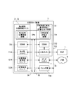
- FIG. 1 shows a configuration example of a wireless communication system according to the embodiment.
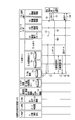
- FIG. 2 shows a configuration example of the access point apparatus (AP) shown in FIG.
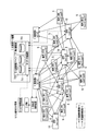
- FIG. 3 shows a configuration example of the disaster server device (disaster server) shown in FIG.
- FIG. 4 shows an example of the location registration sequence.
- FIG. 5 shows an example of an access point release sequence when a disaster occurs.
- FIG. 6 shows an example of a location registration sequence using the access point device.
- FIG. 7 shows an example of a sequence (sequence for transmitting an ETWS signal via an AP) when an aftershock occurs.
- FIG. 8 shows an example of a safety confirmation sequence (information exchange service use sequence) when a disaster occurs.
- FIG. 9 shows an example of an AP recovery sequence after a disaster occurs.
- FIG. 9 shows an example of an AP recovery sequence after a disaster occurs.
- FIG. 10 shows a configuration example of a wireless communication system in the second embodiment.
- FIG. 11 is a diagram schematically illustrating a disaster server device, an access point device, and a mobile terminal.
- FIG. 12 shows a distribution example of the terminals 5.
- FIG. 13A shows an example of the contents stored in the location information management database at the normal time.
- FIG. 13B shows an example of the contents stored in the location information management database when a disaster occurs.
- FIG. 13C shows an example of the contents stored in the location information management database at the time of recovery.
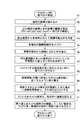
- FIG. 14 is a flowchart showing details of access point distribution processing.
- FIG. 15A is an explanatory diagram of access point distribution processing.
- FIG. 15B is an explanatory diagram of access point allocation processing.
- FIG. 15C is an explanatory diagram of access point allocation processing.
- FIG. 15D is an explanatory diagram of access point distribution processing.
- FIG. 16 shows allocation of each terminal 5 (ID “1” to “12”) stored in the location information management DB 721 to AP # 1 to AP # 4 when the base stations A and B fail (failure). The other example of a state is shown.
- FIG. 17 shows a state when the base station A is restored from the state shown in FIG.
- the following factors can be considered as events that hinder the securing of communication using a terminal in the event of a disaster.
- a disaster occurs, it is conceivable that many users start communication at the same time in the same area. For this reason, in a specific communication infrastructure (for example, a specific base station located in the area), it is conceivable that processing for excessive terminals is concentrated and a congestion state occurs.
- the base station may cause a device failure due to the influence of the disaster, and the connection and communication with the terminal may be disabled.
- a signal including an ETWS (Earthquake and Tsunami Warning System) signal transmitted when an earthquake occurs cannot be transmitted from the base station to the terminal.
- ETWS Earthquake and Tsunami Warning System
- the existing wireless LAN system does not have a specification or function of automatically releasing the access point device free of charge (making it connectable) when a disaster occurs. It also has a specification or function that automatically restores the above-mentioned released state to the original state (a state in which a terminal temporarily connected to the access point device is connected to the original base station device) as necessary. Not. Therefore, even if the access point device can be released manually or the like, it cannot be automatically returned to the original state. For this reason, as long as the state in which the terminal is connected to the access point device continues, the user of the terminal cannot be charged.
- the access point device is prepared by a cellular network carrier (telephone carrier), the burden on the carrier becomes large.
- wireless LAN communication there are many cases where a wireless LAN terminal downloads or uploads large data such as image data or moving image data from an IP (Internet Protocol) network (for example, the Internet).
- IP Internet Protocol
- smartphone applications are GUI-based, and a large amount of data is transmitted and received when the application is executed.
- communication for safety confirmation at the time of a disaster may be hindered.
- a terminal that can be connected to both a cellular network (carrier network) and a wireless LAN (an example of another wireless communication network) is applied. That is, the terminal has a function capable of switching the connection destination between the base station apparatus and a wireless LAN access point apparatus (hereinafter also referred to as “access point”).
- the terminal connected to the base station of the cellular network sends the location information of the terminal itself (user) to the management server device of the carrier network (hereinafter also referred to as “management server”) via the base station. Report.
- the management server of the carrier network transmits the reported location information of the terminal to the disaster server device (hereinafter also referred to as “disaster server” or “disaster server”).
- a wireless LAN access point includes an interface capable of communicating with the management server and the disaster server described above in an emergency including a disaster.
- the disaster server has a function of preliminarily grasping one or more access points used for load distribution by switching from the carrier network to the wireless LAN based on the location information of the terminal.
- the management server can convert the position information of the terminal connected to the carrier network from a format managed by the carrier network into a format for management by the disaster server, and transmit it to the disaster server. By providing such processed location information of the terminal to the disaster server, it is possible to reduce the processing load of the disaster server and to enhance the disaster resistance.
- the disaster server can determine allocation of users to one or more access points used for load distribution based on the location information of the terminals provided from the management server.
- the disaster server knows in advance the distribution of access points and users (terminals) (corresponding relationship between access points and terminals) from the location information. Thereafter, when a disaster occurrence notification (ETWS (Earthquake and Tsunami Warning System) information) occurs, the carrier network base station device (hereinafter also referred to as "base station”) is a signal including ETWS information.
- the terminal transmits an AP release SSID (Service Set Identifier) serving as a trigger for switching from the base station to the access point to each subordinate terminal (broadcast transmission).
- the terminal attempts to connect to the access point (issues a line establishment request) using the SSID for AP release.
- the AP release SSID is an example of “first information”, “information used to determine whether or not to connect to a terminal”, and “information included in a connection request”, and ETWS information (emergency information) is “first information”. 2 "is an example.
- the access point shifts to an acceptance state of the terminal that has received the SSID for AP release under the control of the disaster server. That is, when the disaster server receives an AP release SSID transmission instruction from the management server, the disaster server determines neighboring terminals that should be accommodated by the access point based on the correspondence relationship between the terminal connected to the base station and the access point. Notify the access point. Upon receiving this notification, the access point receives a line establishment request from the terminal using the AP release SSID and establishes a connection with the terminal. A terminal connected to the access point leaves the base station. In this way, it is possible to control the user accommodation status at the base station and access point from the carrier network side. Further, in the above operation, the number of users (terminals) to each access point is distributed by controlling the correspondence between the terminal and the access point to which the terminal is connected, and the terminal is distributed to one base station and one access point. Avoid the situation where people concentrate.
- a base station failure device failure, link failure
- a terminal connected to the base station is accommodated in a nearby access point.
- the terminal accommodated in the access point returns to the connection state to the base station in a predetermined order when the base station recovers from the failure state.
- the disaster server has a unique Web server function.
- an access point AP
- AP access point
- FIG. 1 shows a configuration example of a wireless communication system according to the embodiment.
- FIG. 1 shows an example in which a 3G system (UMTS) is applied as a cellular phone wireless communication network (cellular network: carrier network).
- UMTS 3G system
- cellular networks based on other communication standards such as GSM, LTE, and LTE-Advanced are applicable.
- WiFi was applied as a wireless LAN
- WiMAX wireless communication standards
- a radio communication system is roughly divided into a PSAP (Public Safety Answering Point), a cellular network (carrier network) 1A, a wireless LAN 1B, and an IP (Internet Protocol) network (for example, the Internet). 8 and a disaster server device (disaster server) 7.
- the base station control device 3 and base station device 4, the terminal 5, the carrier management device 6, the disaster server 7, the provider (provider device) 9, and the access point device 10 included in the cellular network 1A are unique. It is possible to communicate using the address.
- the PSAP 1 sends an emergency call in an emergency such as a disaster or an accident.
- the emergency call includes ETWS (Earthquake and Tsunami Warning System) information (emergency information) for notifying an earthquake / tsunami warning.
- ETWS information has a predetermined format.
- the PSTP 1 can make an emergency call including ETWS information by using a predetermined ETWS signal transmission function 11.
- the PSAP 1 is connected to the core network 2 of the cellular network 1A and the disaster server 7 via a communication line, and the ETWS signal is transmitted to the core network 2 and the disaster server 7.
- the cellular network includes a core network 2, a base station control device (called radio network controller: RNC) 3, a base station device (called base station, BTS or Node B (NB)) 4, a carrier management device 6, Is included.
- RNC radio network controller
- NB Node B
- the core network 2 has a connection function to other backbone networks such as the Internet and ISDN network, and a connection function between a mobile telephone network and a fixed telephone network.
- the core network 2 includes one or more core network devices (core NW devices) 21 such as SIN (Signaling Interworking Node for 3G access) and xGSN (serving / gateway General packet radio service Support Node).
- the core network device 21 has an interface circuit for connecting to the IP-compatible base station controller 3 (IP-RNC) via a communication line, and an interface circuit for receiving an ETWS signal from the PASP1.
- IP-RNC IP-compatible base station controller 3
- ETWS ETWS signal from the PASP1.
- an existing core network device that conforms to a predetermined communication standard such as 3GPP can be applied.
- the base station control device 3 is a control device that collects the base stations 4.
- the base station control device 3 has a 3GPP protocol function 31.
- the 3GPP protocol function 31 is a 3GPP-compliant interface for performing communication between the base station control device 3 and each node (for example, the base station 4 and the carrier management device 6). 6 is realized by an interface circuit to be connected to 6 through a communication line.
- the base station control device 3 can be an existing base station control device that conforms to a predetermined communication standard such as 3GPP.
- the base station 4 is an IP compatible base station (IP-BTS), forms an area (cell) to which the terminal 5 is connected wirelessly, and performs wireless communication with the terminal.
- IP-BTS IP compatible base station
- the base station 4 has a wireless communication function 41 and a 3GPP protocol function 42.
- the wireless communication function 41 performs wireless communication with the terminal 5.
- the wireless communication function 41 transmits and receives wireless signals including 3GPP-compliant position information.
- the 3GPP protocol function 42 is a 3GPP-compliant interface for communicating with the base station control device 3, and is realized by an interface circuit for connecting to the base station control device 3 via a communication line.
- the base station 4 can apply the existing base station apparatus based on a predetermined communication standard such as 3GPP.
- one base station control device 3 and one base station 4 are illustrated, but actually, a plurality of base station control devices 3 and a plurality of base stations 4 each having the functions described above. Is installed.
- a terminal for example, a smartphone or a feature phone having both a function (cellular phone (UE) function) as a connection terminal (called User Equipment (UE)) to the cellular network 1A and a wireless LAN terminal function , PDA, etc.) are applied.
- the terminal 5 has a wireless communication function 51.
- the wireless communication function 51 includes a function capable of selectively connecting to the cellular network 1A and the wireless LAN 1B, and a function of performing signal transmission / reception including position information compliant with 3GPP and wireless LAN communication.
- the terminal 5 performs wireless communication with the base station 4 when connected to the cellular network 1A (base station 4).
- the terminal 5 includes a UE function module for performing transmission / reception of a radio signal including 3GPP-compliant position information with the base station 4.
- the terminal 5 includes a wireless LAN connection module (wireless LAN terminal function module) for performing a connection process with the access point device 10 and performing wireless communication including data during wireless LAN connection.
- the terminal 5 also performs authentication using an SSID or the like when connected to the wireless LAN.
- the functions of the terminal 5 described above are functions of existing smartphones, feature phones, and the like, and existing smartphones, feature phones, and the like can be applied.
- the terminal 5 receives an ETWS4Paging signal including the SSID for AP release from the base station 4.
- the terminal 5 turns ON if the wireless LAN connection module is OFF, and executes the wireless LAN connection using the SSID included in the ETWS Paging signal. It further includes functions.
- the terminal 5 When attempting a wireless LAN connection, the terminal 5 receives surrounding radio waves and checks whether or not it can connect to the access point that is the transmission source of the received radio waves. The terminal 5 also checks that it is at the security level at the time of the confirmation. In the confirmation process, if the SSID requested by the access point is unknown, the connection is rejected by security.
- the terminal 5 Upon receiving the ETWSETPaging signal, the terminal 5 checks the AP release SSID included in the ETWS Paging signal, and searches for an access point that can be connected using the AP release SSID. As a result, the terminal 5 can connect to an access point that gives permission for access (connection request: line establishment request) from the terminal 5 using the release SSID.
- the terminal 5 connected to the access point can transmit / receive information to / from the access point on condition that the unique identifier (terminal ID) of the terminal 5 matches the terminal ID of the access point. .
- the terminal ID is supplied from the disaster server to the access point.
- the carrier management device (cellular network management device) 6 is a server that manages the cellular network 1A, and can be realized by application of a dedicated or general-purpose computer (information processing device) or a dedicated or general-purpose server machine.
- the carrier management device 6 includes a 3GPP protocol function 61, a location information manager 62, and an IP-IF (IP network interface) controller 63.
- the 3GPP protocol function 61 is a 3GPP-compliant interface for communicating with the base station control device 6, and is realized by an interface circuit connected to the core network device 21 of the core network 2 via a communication line.
- the location information manager 62 manages location information of the terminal 5 connected to the cellular network 1A (base station 4) using a location information management database (location information management DB) 63.
- the location information management DB 63 is a database (DB) that stores location information of the terminal 5.
- the location information can include, for example, information of the base station 4 to which the terminal 5 is connected in addition to the location information of the terminal 5.
- the IP-IF controller 63 is an IP interface (LAN chip, LAN card) having an interface circuit for connecting to an IP network (Internet) 8.
- the disaster server 7 is realized by using a dedicated or general-purpose computer (personal computer (PC), workstation (ST), etc.).
- the disaster server 7 includes a web function 71, a location information manager 72, a controller 73 that performs ETWS processing (release and recovery control) and AP distribution control, and an IP-IF controller 74.
- the Web function 71 includes a GUI (Graphical User Interface) engine and a CUI (Character User Interface) engine, and uses a Web database (WebDB) 711 to perform unique Web management (information exchange service (for example, information exchange service (for example, Support for bulletin boards (BBS) and Twitter (registered trademark)).
- WebDB 711 is a database that stores data and information for the Web function 71 to perform Web management.
- the WebDB 711 stores GUI (graphical user interface) and CUI (character user interface) display data (UI display data).
- the UI display data is provided (downloaded) to the terminal 5 for use of a bulletin board or Twitter provided to the terminal 5 when a disaster occurs.
- the UI display data is, for example, display data in which the data amount is reduced as much as possible compared to a normal UI by being created on a text basis.
- the location information manager 72 manages the location information of the terminal 5 received from the carrier management device 6. That is, the location information manager 72 stores the location information of the terminal 5 received from the carrier management device 6 in the location information management DB 721 and manages the terminal 5 using the location information.
- the location information manager 72 uses the access point (AP) information DB 722 to manage the information of the access point 10 connected to the information of the terminal 5 whose connection destination is switched from the cellular network 1A to the wireless LAN 1B in the event of a disaster.
- the AP information DB 722 can store a correspondence relationship between information (AP information) of the access point 10 that can be switched from the base station 4 at the time of a disaster and the terminal 5 connected to the access point 10 by the switching process.
- the information of the terminal 5 includes a terminal ID that is unique identification information of the terminal 5.
- the AP information includes an AP release SSID (AP release SSID) that the access point 10 whose use is released (can be used without charging) at the time of a disaster or the like uses to accept the terminal 5.
- the AP release SSID can be configured to be statically stored in a storage device (eg, flash ROM 734, FIG. 3) of the disaster server 7.
- a configuration in which the disaster server 7 receives the AP release SSID transmitted from the core network device 21 via the carrier management device 6 may be adopted.
- the core network device 21 transmits the AP release SSID to the base station control device 3, the information (base station ID) of each base station 4 accommodated by the base station control device 3 and the AP release SSID are stored.
- the information is sent to the carrier management apparatus 6 in association with it.
- the carrier management device 6 sends the AP release SSID and the base station ID to the disaster server 7 via the IP network 8.
- the disaster server 7 for example, in the location information management DB 721, the correspondence relationship between the base station 4 and the AP 10 (base station ID and AP 10 ID (AP-ID)) are stored in association with each other.
- the disaster server 7 Upon receiving the base station ID, the disaster server 7 (for example, the location information manager 72 or the controller 73) stores the AP release SSID in association with the base station ID and the AP-ID in the location information management DB 721.
- the SSID is used when the AP is released.
- the controller 73 performs a process of distributing the terminals 5 connected to the base station 4 to the appropriate access points 10 based on the position information of the terminals 5 stored in the position information management DB 721. In addition, the controller 73 instructs the access point 10 release processing and recovery (release state release) at the time of a disaster. Further, the controller 73 processes the ETWS information that reaches the disaster server 7 via the PSAP1 or the wireless LAN 1B.
- the IP-IF controller 74 is an IP interface (LAN chip, LAN card) having an interface circuit for connecting to the IP network 8.
- the disaster server 7 is connected to the carrier management device 6, the provider device (provider) 9, and the access point 10 via the IP network 8. As a result, the disaster server 7 can receive location information from the carrier management device 6 and accept access to the Web function 71 (bulletin board, Twitter) from the access point 10.
- the provider 9 is a vendor apparatus that accommodates the access point 10 and operates the access point 10 by performing an access point (AP) control 91.
- AP access point
- the access point device 10 forms the wireless LAN 1B and can accommodate the terminal 5 through connection processing. Although one AP 10 is illustrated in FIG. 1, in reality, two or more APs 10 can be arranged in the communication area (cell) of the base station 4 or in the vicinity of the cell. AP10 is arrange
- the AP 10 includes a release / recovery manager 101, an ETWS information transmission function 102, a wireless communication function 103, and an IP-IF controller 104.
- the release / recovery manager 101 performs control of the terminal 5 that is the accommodation target terminal of the AP 10 at the time of a disaster, and eviction control of the terminal 5 that is the accommodation target terminal at the time of recovery (when the release state is released). Furthermore, the release / recovery manager 101 enables an ETWS signal to be transmitted via the AP 10 when the AP 10 is released.
- the ETWS information transmission function 102 transmits ETWS information via the AP 10.
- the wireless communication function 103 is a wireless interface including an interface circuit that performs transmission / reception of signals including position information compliant with 3GPP and wireless LAN communication.
- the functions or processes of the PSAP 1, the core network device 21, the base station control device 3, the base station 4, the carrier management device 6, and the terminal 5 shown in FIG. 1 are, for example, dedicated or general-purpose electric / electronic circuits (for example, IC , An integrated circuit such as an LSI or an ASIC).
- a part of the above functions or processing is performed by a processor (for example, a CPU (Central Processing Unit), a DSP (Digital Signal Processor)), an auxiliary storage device, and a main storage device. It can be realized by loading the stored program into the main storage device and executing it.
- a part of the above functions or processing can be realized by a programmable logic device (PLD) such as FPGA (Field Programmable Gate Array) or CPLD (Complex Programmable Logic Device).
- PLD programmable logic device
- FPGA Field Programmable Gate Array
- CPLD Complex Programmable Logic Device
- the function or process can be realized by a combination using at least two of the hardware configuration, the processor configuration, and the PLD as described above.
- the location information management DB 63 shown in FIG. 1 is created on a storage area of a storage device (storage) included in the carrier management device 6. Further, the Web DB 711, the location information management DB 721, and the AP information DB 722 included in the disaster server 7 are created on a storage area of a storage device (storage) included in the disaster server 7.
- FIG. 2 shows a configuration example of the access point device 10 (AP 10) shown in FIG.
- the AP 10 includes a CPU 111, an SDRAM 112, and a flash ROM 113 that are connected to each other via a bus B1.
- the AP 10 also includes a wireless module 115 connected to the CPU 111 via the bus B2 and an IP-IF controller 104, and an antenna 114 is connected to the wireless module 115.
- the CPU 111 is an example of a processor or a control device
- the SDRAM 112 is an example of a main storage device (storage device)
- the flash ROM 113 is an example of an auxiliary storage device (storage device).
- the CPU 111 can function as the release / recovery manager 101 and realize the ETWS information transmission function 102 by loading the program stored in the flash ROM 113 into the SDRAM 112 and executing it.
- the antenna 114 and the wireless module 115 realize the wireless communication function 103 described above.
- the wireless module 115 is formed by a group of electric and electronic circuits forming a down converter and up converter between RF (radio frequency) and IF (intermediate frequency), a signal amplifier, an analog-digital converter, and a digital-analog converter.
- the wireless module 115 performs baseband signal generation processing, baseband signal demodulation processing, and decoding processing, so that user data from the terminal 5 can be obtained.
- the CPU 111 generates an IP packet including user data.
- the IP-IF controller 104 generates a LAN frame including the IP packet received from the CPU 111 and sends it to the IP network 8.
- FIG. 3 shows a configuration example of the disaster server 7 shown in FIG. 3
- the disaster server 7 shown in FIG. 3 has a hardware configuration in the case of using a PC hardware architecture.
- the disaster server 7 includes an SDRAM 732, an input / output port 733, an IP-IF controller 74, and a flash ROM 734 connected to the CPU 731 via the bus B3.
- the disaster server 7 includes an SDRAM 735 connected to the CPU 731 via the bus B4, a storage (storage device) 711A that stores the WebDB 711, a storage (storage device) 721A that stores the location information management DB 721, an AP And a storage (storage device) 722A in which the information DB 722 is stored.
- the CPU 731 is an example of a processor (control device), the SDRAMs 732 and 735 are examples of a main storage device, and the flash ROM 734 and the storages 711A, 721A, and 722A are examples of an auxiliary storage device. Note that one SDRAM can be applied instead of the SDRAMs 732 and 735. Further, instead of the storages 711A, 721A, and 722A, one or two storages can be applied.
- the CPU 731 functions as the controller 73 that performs ETWS processing and AP distribution control, for example, by loading a program stored in the flash ROM 734 into the SDRAM 732 and executing it.
- the input / output port 733 is connected to the PSAP 1 via a communication line, and can receive an ETWS signal from the PSAP 1 and supply it to the CPU 731.
- the CPU 731 performs ETWS processing using the ETWS signal.
- the IP-IF controller 74 is connected to the IP network 8 via a communication line.
- the IP-IF controller 74 receives position information of the terminal 5 from the carrier management device 6 and supplies it to the CPU 731.
- the CPU 731 functions as the position information manager 72 to register the position information in the position information management DB 721A.
- the CPU 731 executes AP distribution processing using the location information of the terminal 5 stored in the location information management DB 721A and the AP information stored in the AP information DB 722.
- the CPU 731 reads out the UE display data stored in the WebDB 711 in response to a bulletin board or Twitter access request received from the terminal 5 received by the IP-IF controller 74, and generates a packet including the UE display data. Then, it can be transmitted to the terminal 5 through the IP-IF controller 74.
- FIG. 4 shows an example of the location registration sequence. 4 indicates 3GPP communication (cellular network communication), and the solid line arrow indicates IP packet communication or internal communication of the apparatus.
- the terminal 5 connected to the base station 4 acquires the position information of the terminal 5 itself ( ⁇ 1> in FIG. 4). The acquired position information is transmitted to the base station 4 by a measurement signal by the wireless communication function 51 ( ⁇ 2> in FIG. 4).
- the location information is received by the wireless communication function 41 of the base station 4 and transmitted to the base station control device 3 by the 3GPP protocol function 42 ( ⁇ 3> in FIG. 4).
- the base station control device 3 sends location information to the core network 2 (core network device) 21 by the 3GPP protocol function 31 ( ⁇ 4> in FIG. 4).
- the core network device 21 transmits the position information to the carrier management device 6 ( ⁇ 5> in FIG. 4).
- the location information manager 62 registers the location information in the location information management DB 63.
- the location information manager 62 converts (processes) the location information registered in the location information management DB 63 into a format for transmission to the disaster server 7 and sends it to the disaster server 7 as location information data ( ⁇ 6> in FIG. 4).
- the position information data includes identification information (terminal ID) of the terminal 5 connected to the base station 4.
- the location information manager 72 stores location information data in the location information management DB 721.
- the position information data is transferred to the position information manager 72 and registered in the position registration DB 721 ( ⁇ 7> in FIG. 4).
- the position information of the terminal 5 is collected by the Measurement signal before the disaster occurs and is managed by the position information management DB 63.
- the location information is also registered in the location information management DB 721 in the disaster server 7.
- mapping of the terminal 5 based on the position information is performed as AP distribution control by the controller 73. That is, the controller 73 uses the location information of the AP 10 of the wireless LAN 1B registered in advance in the AP information DB 722 as mapping, and associates the terminal 5 with the AP 10 that is the distribution destination (allocation destination) at the time of a disaster. (Calculate the allocation forecast).
- the result of the mapping (allocation prediction) is registered in the position information management DB 721.
- mapping is executed for each base station 4.
- the mapping can be executed for all terminals 5 connected to one base station 4. This is because the base station 4 may not be able to maintain a proper connection state with the subordinate terminals 5 due to a device failure or link failure of the base station 4 due to a disaster.
- the base station 4 when there is little possibility that the base station 4 is in a failure state at the time of a disaster, it is conceivable to distribute the load between the base station 4 and one or more APs 10.
- the number of terminals 5 that maintain the connection with the base station 4 regardless of the release of the AP 10 is determined as a threshold, and among the terminals 5 connected to one base station 4, the amount exceeding the threshold Mapping for the terminal 5 may be executed.
- an upper limit can be set for the number of terminals 5 accepted by one AP 10.
- the upper limit can be determined in consideration of, for example, radio resources used by the terminal 5 and buffer resources for data transfer.
- a plurality of terminals 5 are associated with one or more APs 10 so as not to exceed the determined upper limit. In this way, load distribution can be achieved among a plurality of APs 10.
- the terminal 5 switched to the AP 10 is in a state in which only text-based communication for obtaining information related to the disaster is possible. For this reason, the upper limit of the resource amount to be allocated to one terminal 5 can be assumed, and the above-described upper limit can be easily determined.
- the location registration sequence described above is performed at least when the terminal 5 is newly connected to the base station 4.
- the information on the terminal 5 is deleted from the location information management DB 62 of the carrier management device 6, and the disaster
- the information on the terminal 5 is also deleted from the location information management DB 721 of the server 7, and the mapping (association) between the terminal 5 and the AP 10 is updated.
- FIG. 5 shows an example of an access point release sequence when a disaster occurs. Due to the occurrence of a disaster (for example, an earthquake), an emergency call is transmitted from the PSAP1 to the core network device 21 ( ⁇ 1A> in FIG. 5). The emergency call is also transmitted to the disaster server 7 (FIG. 5 ⁇ 1B>).
- a disaster for example, an earthquake
- the emergency call is also transmitted to the disaster server 7 (FIG. 5 ⁇ 1B>).
- the controller 73 In the disaster server 7, the controller 73 generates a release instruction message for the AP 10.
- the AP release instruction is transmitted to the AP 10 and the provider 9 via the IP network 8 ( ⁇ 3> in FIG. 5).
- the provider 9 receives the AP release instruction
- the provider 9 enters a state in which the charging process for the use of the AP 10 using the release SSID is not executed.
- Provider 9 performs the following processing as AP control 91. That is, the provider 9 includes a billing server that performs billing processing for a terminal using a wireless LAN.
- the provider 9 (billing server) receives information (for example, SSID and terminal ID) of the terminal (user) connected to the AP 10 from the disaster server 7 or the AP 10 through the IP network 8, and performs billing (accumulation of billing).
- the provider 9 receives an AP release instruction from the disaster server 7 via the IP network 8.
- the AP release instruction includes the AP release SSID and the terminal ID of the terminal 5 that can use the access point 10 using the AP release SSID.
- the provider 9 that has received the AP release instruction temporarily stops charging for the wireless LAN usage of the terminal (terminal ID) using the release SSID.
- the provider 9 (charging server) receives SSID, terminal ID, and charging information (for example, packet amount) as user information related to charging. Then, the provider 9 determines whether or not the SSID and terminal ID included in the user information match the AP release SSID and terminal ID acquired by receiving the AP release instruction. When the SSID and the terminal ID match, the provider 9 does not perform the charging process for the terminal 5 (user) having the terminal ID. Therefore, during the AP release, the terminal 5 using the wireless LAN using the AP releasing SSID can use the wireless LAN free of charge.
- charging information for example, packet amount
- the provider 9 receives the AP restoration instruction including the release SSID and the terminal ID and the release SSID invalidation notification (FIG. 9), the terminal 5 (user) identified by the AP release SSID and the terminal ID ) Resume billing.
- the AP return instruction is transmitted from the disaster server 7 to the provider 9 through the IP network 8.
- the provider 9 (billing server) the following configuration can be adopted instead of the above configuration. For example, a configuration in which only the release SSID is notified from the disaster server 7 to the provider 9 can be applied. In this case, the provider 9 determines whether or not the SSID in the user information received from the AP 10 matches the release SSID. When the SSIDs match, the provider 9 does not perform (avoids) the charging process for the terminal 5 (user) having the terminal ID in the user information.
- the provider 9 stores the AP release SSID in the storage device in advance.
- the provider 9 determines whether or not the SSID in the user information matches the AP release SSID. If the two match, the provider 9 avoids the charging process related to the terminal ID in the user information.
- the release / recovery manager 101 shifts the AP 10 to the AP release mode ( ⁇ 4> in FIG. 5).
- the core network device 21 that has received the emergency call stores the AP release SSID on its own storage device, and ETWS WriteReplace including the release SSID and the emergency information (ETWS information) included in the emergency call.
- the signal is transmitted to the base station controller 3 ( ⁇ 5> in FIG. 5).
- the base station controller 3 transmits an ETWS Paging signal carrying the SSID for AP release and the ETWS indication information (etws-indication) to the base station 4 ( ⁇ 6> in FIG. 5).
- the AP release SSID is held in advance by the core network device 21, but the base station controller 3 or the base station 4 stores the AP release SSID in advance and includes it in the ETWS Paging signal. It may be adopted.
- one of SSID (common ID) common to APs and unique SSID (unique ID) can be applied as the SSID for AP release.
- the upstream device for example, the core network device 21
- unique SSID unique ID
- the base station 4 transmits an ETWS Paging signal carrying the AP release SSID and the ETWS indication information (etws-indication) to the terminal 5 under its control ( ⁇ 6A> in FIG. 5).
- the terminal 5 can receive (receive) the AP release SSID by receiving the ETWS Paging signal carrying the AP release SSID and the ETWS indication information (etws-indication) from the base station 4 (FIG. 5 ⁇ 6B>). ).
- the “ETWS-Paging signal” is provided with an SSID for AP release and ETWS indication information (etws-Indication).
- the terminal 5 attempts to receive the paging signal intermittently at a predetermined cycle (in the 3GPP specification, for example, 320 msec, 640 msec, 1.28 sec, 2.56 sec can be set).
- the terminal 5 compliant with the 3GPP specification includes emergency information (ETWS information (ETWSPprimary ⁇ ⁇ notification, ETWS secondary notification)) when detecting a Paging signal (ETWS-Paging) to which "etws-Indication" is added. Start receiving broadcast information.
- EWS information EWSPprimary ⁇ ⁇ notification, ETWS secondary notification
- Paging signal Etws-Indication
- the first emergency information “ETWS primary” notification ” uses SIB10 (System Information Block Type 10) notification information
- the second emergency information“ ETWS secondary notification ” is SIB11 (System Information). It is transmitted from the base station 4 using the broadcast information of Block Type 11).
- the ETWS information received from the core network device 21 by the base station control device 3 is transmitted to the base station 4, and the base station 4 provides the ETWS information to the terminal 5 using the notification information described above.
- the terminal 5 compliant with the 3GPP specification may perform notification processing such as sounding a warning sound when detecting a Paging signal to which “etws-Indication” is added.
- the base station control device 3 receives an ETWS-Paging signal further including ETWS information received from the core network device 21 in addition to the AP release SSID and ETWS indication information (etws-Indication). It can be transmitted to the base station 4 as an ETWS signal.
- the base station 4 transmits the ETWS signal to the terminal 5, and the terminal 5 acquires the release SSID and ETWS information from the ETWS signal.
- the timing at which the terminal 5 acquires ETWS information can be advanced.
- ETWS information (etws-information) in the ETWS-Paging signal is optional information (additional information).
- the terminal 5 can acquire ETWS information by detecting (recognizing) additional information in the ETWS-Paging signal (a normal Paging signal and a Paging signal including ETWS information can be distinguished). In this configuration, it is expected that the terminal 5 acquires the ETWS information earlier than the case where the ETWS information is acquired from the broadcast information.
- the terminal 5 When the terminal 5 receives the AP release SSID from the base station 4, the terminal 5 enters a state of transmitting a line establishment request having the AP release SSID and the terminal ID of the terminal 5 itself to the AP 10.
- a unique value (unique ID) for each AP may be applied, or a common value (common ID) may be applied among all the released APs.
- the terminal 5 transmits a connection establishment request only to the corresponding AP 10 using the unique ID assigned to itself. For this reason, each AP 10 can avoid receiving a connection establishment request from an irrelevant terminal. In other words, the AP 10 can effectively avoid the possibility of congestion in processing for connection establishment requests from a large number of unrelated terminals (decoding processing for connection establishment requests, transmission processing for rejection responses, etc.).
- each AP 10 compares the terminal ID included in the connection establishment request (the ID of the terminal 5 itself) with the terminal ID included in the reception instruction received in advance. Establish a connection if they match. Conversely, when the terminal IDs do not match, the connection between the terminal 5 and the AP 10 is not established. In this way, each AP 10 can avoid establishing a connection with an irrelevant terminal to which no connection is assigned.
- the unique ID may be set.
- the common ID when the common ID is used, for example, in the LTE communication method, the common ID may be set as an information element immediately below the Paging information defined in 3GPP TS36.331 Sec6.2.2.
- Paging information element when the unique ID is used and a specific example of the Paging information element when the common ID is used are shown below.
- various types of information related to the authentication method, encryption method, authentication key, etc. may be acquired from each AP 10 in advance and stored and managed in association with each AP. May be.
- various information on the authentication method, encryption method, and authentication key shown in the following example may be included together with the release SSID and transmitted to each AP.
- the controller 73 of the disaster server 7 that has received the emergency call makes an AP location / terminal location information request to the location information manager 72 ( ⁇ 7> in FIG. 5).
- the location information manager 72 returns an AP location / terminal location information response including the mapping result (correspondence between the AP 10 and the terminal 5) and the destination address (address of the destination AP 10) to the controller 73. (FIG. 5 ⁇ 8>).
- the controller 73 generates a terminal acceptance instruction message for instructing the AP 10 to accept the terminal 5 using the correspondence relationship between the AP 10 and the terminal 5 included in the AP position / terminal position information response, and transmits the terminal acceptance instruction message to the AP 10.
- the terminal acceptance instruction message includes at least an AP release SSID (common ID or unique ID) and a terminal ID of at least one terminal 5 that can accept the terminal.
- the terminal acceptance instruction message is an example of an acceptance instruction.
- the AP release SSID can be stored in advance in a storage device (for example, the flash ROM 734). Alternatively, the disaster server 7 can receive from the core network device 21 via the carrier management device 6.
- one of transmission (unicast) destined for the address of a predetermined AP 10 and transmission (multicast) designating a group (multicast group) of the destination AP 10 can be applied.
- the controller 73 When unicast is applied, the controller 73 sends a terminal acceptance instruction including an AP release SSID (common ID or unique ID) and a terminal ID of at least one terminal 5 that can be accepted to the destination AP 10. Send by specifying an address.
- the destination AP 10 performs an accepting process for the terminal 5 using the AP release SSID and at least one terminal ID included in the terminal accepting instruction that has arrived at itself.
- the controller 73 sends a terminal acceptance instruction including an AP release SSID (common ID or unique ID) and a terminal ID of at least one acceptable terminal 5 to a plurality of predetermined APs 10. Specify the multicast address of the multicast group to which the belongs.
- the AP 10 belonging to the multicast group performs the accepting process of the terminal 5 using the AP release SSID and at least one terminal ID included in the arrived terminal accepting instruction.
- the unique ID is applied as the SSID for AP release, the following processing is performed.
- each AP 10 stores a unique ID in a storage device in advance, and selects an AP release SSID that matches an AP release SSID stored in advance among a plurality of AP release SSIDs included in the terminal acceptance instruction. Used for terminal acceptance processing. Multicast is applied, for example, when a suitable communication environment can be provided regardless of which terminal 5 is connected between a plurality of APs 10. When multicast is performed, the time until the terminal 5 is connected to the AP 10 can be shortened as compared with a case where a terminal acceptance instruction by unicast is sequentially performed.
- the terminal acceptance instruction includes a plurality of unique IDs and identification information of the AP 10 corresponding to each unique ID (each AP 10 is stored in advance) in association with each other, and the unique ID that matches the identification information is used for the terminal acceptance process.
- the identification information of the AP 10 may be anything that can be distinguished between the APs 10. For example, as the identification information of the AP 10, an address of the AP 10 or an SSID that is normally used (except when the AP is released) can be applied.
- a terminal acceptance instruction including the terminal ID of the terminal may be multicast or broadcast.
- transmission of a terminal acceptance instruction related to one terminal 5 to one AP 10 may be performed once or may be performed in a plurality of times. Further, a terminal acceptance instruction for one terminal 5 may be performed simultaneously for a plurality of APs 10.
- the release / recovery manager 101 determines the corresponding AP 10 for each terminal, and accepts the terminal including one AP release SSID and one acceptable terminal ID for the AP 10.
- An example in which the instruction is transmitted by unicast is shown.
- the transmission of the terminal acceptance instruction can also be executed in AP units.
- the release / recovery manager 101 searches for the terminal 5 to be accepted using the wireless communication function 103 based on the AP release SSID included in the terminal acceptance instruction ( ⁇ 10> in FIG. 5). ). The search is performed based on whether the signal (line establishment request) received from the wireless LAN terminal received by the wireless communication function 103 includes the same AP release SSID as the AP release SSID included in the terminal acceptance instruction. Can do. At this time, if the signal including the SSID for AP release is not received, that is, if the terminal 5 to be accepted is not found (connection is impossible), the release / recovery manager 101 sends a terminal confirmation failure notification to the controller of the disaster server 7. 73 (FIG. 5 ⁇ 11>).
- the AP 10 determines that the terminal ID included in the detected line establishment request and the terminal ID included in the terminal acceptance instruction are Contrast with. If the terminal IDs do not match in the comparison result, the AP 10 sends a terminal confirmation impossible notification to the disaster server 7 ( ⁇ 11> in FIG. 5).
- the terminal confirmation impossibility notification may include the AP release SSID and the terminal ID included in the terminal acceptance instruction.
- the processes ⁇ 7> to ⁇ 10> described above are executed for each terminal 5 in which position information is registered in the position information management DB 721.
- the controller 73 starts a process for instructing the alternative AP 10 to accept the terminal 5 related to the terminal confirmation impossibility notification.
- the controller 73 can identify the AP 10 that could not accommodate the target terminal 5 from the transmission source address (the address of the AP 10) of the terminal confirmation impossibility notification.
- the controller 73 that has received the terminal confirmation impossibility notification by the processing of ⁇ 11> obtains the AP position / terminal position information having the terminal ID and the address of the AP 10 in the terminal confirmation impossibility notification in order to search for an alternative AP 10.
- Request is made to the manager 72 (FIG. 5 ⁇ 12>), and a response including the corresponding AP location / terminal location information is obtained from the location information manager 72 (FIG. 5 ⁇ 13>).
- the response includes the address of the alternative AP 10.
- a terminal acceptance instruction is transmitted to the corresponding AP 10 (alternate AP 10) ( ⁇ 14> in FIG. 5).
- the AP 10 searches for the terminal 5 ( ⁇ 15> in FIG. 5). That is, the AP 10 searches for a line establishment request from the terminal 5 including the same AP release SSID as the AP release SSID included in the terminal acceptance instruction, and the terminal ID contained in the line establishment request and the terminal acceptance The terminal ID included in the instruction is compared. If the terminal IDs match in the comparison result, the AP 10 executes a line establishment procedure with the terminal 5 ( ⁇ 16> in FIG. 5). When the AP connection is completed, the terminal 5 releases the connection with the base station 4. However, the connection cancellation with the base station 4 may be performed before the AP connection is completed.
- the AP 10 can have a configuration in which the AP 10 forcibly transitions to a connectable state with the wireless LAN terminal when the AP 10 receives the AP release instruction.
- the CPU 111 receives an AP release instruction from the IP-IF controller 104 when the wireless module 115 that controls the wireless communication function 103 and the antenna 114 are in an operation stop state due to power supply stop or the like, Then, the power supply to the wireless module 115 and the antenna 114 is started, and the connection (line establishment) with the terminal 5 is enabled.
- the controller 73 When the number of terminals 5 whose position information is registered in the position information management DB 721 is less than a predetermined threshold (there is a sufficient number of terminals 5 connected to the base station 4), the controller 73 The operation stop instruction can be transmitted to the AP 10.
- the CPU 111 that has received the operation stop instruction stops power supply to the wireless module 115 and the antenna 114 so that the terminal 5 continues to connect to the base station 4.
- the terminal ID since the terminal ID is not provided to the AP 10, even if the release SSID matches in the line establishment request from the terminal 5, the terminal ID cannot be matched. As a result, the terminal 5 cannot connect to the AP 10 and maintains the connection state with the base station 4.
- the base station control device 3 transmits an ETWS-Paging signal including an AP release SSID to the base station 4 upon receipt of an emergency call.
- an ETWS-WriteReplace signal including an AP release SSID and ETWS information is transmitted to the base station controller 4, and all terminals 5 connected to the base station 4 are notified of the AP.
- An ETWS-Paging signal including the release SSID is transmitted. Thereby, each terminal 5 can acquire the AP release SSID.
- Each terminal 5 can acquire ETWS information from broadcast information or an ETWS-Paging signal.
- the controller 73 of the disaster server 7 transmits a release instruction to the AP 10.
- the AP 10 searches for the peripheral terminals 5 that can be accommodated and tries to establish a line.
- the AP 10 can receive a signal (line establishment request) from the terminal 5 making a line connection request using the SSID for AP release.
- the AP 10 performs a line establishment procedure with the terminal 5 and secures a communication band.
- the alternative AP 10 an adjacent AP 10 in the vicinity
- a terminal disconnection notification (including the AP release SSID and the terminal ID) is transmitted from the AP 10 to the disaster server 7.
- the disaster server 7 can perform the same process as when the terminal confirmation impossibility notification is received, and transmit a terminal acceptance instruction to a substitute AP 10 (for example, another nearby AP 10).
- FIG. 6 shows an example of a location registration sequence of the terminal 5 using the AP 10.
- the terminal 5 transmits the position information to the AP 10 at least once (for example, during the line establishment procedure) ( ⁇ 1> in FIG. 6).
- the position information may include the terminal ID, the address of the terminal 5, the position information (x / y coordinates) of the terminal 5, and the identification information of the AP 10.
- the AP 10 Upon receiving the location information, the AP 10 generates a packet including the location information and transmits the packet (location information data) to the disaster server 7 via the IP network 8 ( ⁇ 2> in FIG. 6).
- the position information data is stored in the position information management DB 721 by the position information manager 72.
- the disaster server 7 can receive the transmission source address of the packet including the location information as the specific information of the AP 10 to which the terminal 5 is connected. In this way, for each AP 10 registered in the AP information DB 722, information on the terminal 5 connected to each AP 10 is managed by releasing the AP. Note that the location registration of the terminal 5 using the AP 10 can be performed at an appropriate timing as necessary.
- the first location information data is handled as a notification indicating the success of the line establishment procedure in the disaster server 7. That is, the disaster server 7 can recognize the connection (line establishment) between the terminal 5 and the AP 10 by receiving the position information data. However, prior to location registration, for example, after the procedure of ⁇ 16> in FIG. 5, a notification indicating a successful line establishment may be transmitted to the disaster server 7.
- FIG. 7 shows an example of an aftershock sequence (sequence for transmitting ETWS information (emergency information) via AP).
- An emergency call (including ETWS information) is sent from PSAP1 every time an earthquake occurs. For this reason, after an earthquake occurs, an emergency call (including ETWS information) is transmitted from PSAP1 every time an aftershock of the earthquake occurs.
- the emergency call is received by the core network device 21 ( ⁇ 1A> in FIG. 6).
- the emergency call is also received by the disaster server 7 ( ⁇ 1B> in FIG. 6).
- the controller 73 inquires the location information manager 72 about the information of the terminal 5 to which the ETWS information should be transmitted ( ⁇ 2> in FIG. 7: terminal information acquisition request).
- the location information manager 72 refers to the location information management DB 721, reads the information of the location registered terminal 5, and returns it to the controller 73 (FIG. 7 ⁇ 3>: terminal information acquisition response).
- the controller 73 generates a packet including the ETWS information, sets the address of the terminal 5 included in the information of the terminal 5 obtained from the location information manager 72 to the packet, and sends the packet to the IP network 8 ( ⁇ 4> in FIG. 7: ETWS information transmission instruction via AP).
- the ETWS information transmission process 102 is executed, and a baseband signal including ETWS information is given to the wireless communication function 103 (wireless module 115) (FIG. 7 ⁇ 5>): ETWS transmission instruction).
- the wireless communication function 103 (wireless module 115) generates an RF signal including ETWS information and transmits it from the antenna 114 (FIG. 7 ⁇ 6>: ETWS transmission).
- the terminal 5 can receive the ETWS information that can be received when the base station 4 is connected via the AP 10 even after switching to the AP 10. That is, while the line with the AP 10 is maintained, the ETWS information notified when an aftershock occurs or the like is notified from the AP 10 to the terminal 5 via the disaster server 7.
- Safety confirmation sequence in the event of a disaster >>>>>>> The terminal 5 connected to the AP 10 uses an information exchange service such as a bulletin board or Twitter (registered trademark) using the UI display data prepared in the disaster server 7 by using the Web function 71 of the disaster server 7. can do. The user of the terminal 5 can use the information exchange service for safety confirmation.
- an information exchange service such as a bulletin board or Twitter (registered trademark) using the UI display data prepared in the disaster server 7 by using the Web function 71 of the disaster server 7. can do.
- the user of the terminal 5 can use the information exchange service for safety confirmation.
- FIG. 8 shows an example of a safety confirmation sequence (information exchange service use sequence) when a disaster occurs.
- the location management manager 72 of the disaster server 7 gives a URL provision request for the terminal 5 to the Web function 71 when the location of the location of the terminal 5 in the location information management DB 721 is triggered ( ⁇ 1> in FIG. 8).
- the Web function 71 generates a packet including an address (URL (Uniform Resource Locator)) of an information exchange service site such as a bulletin board or Twitter (registered trademark) supported by the Web function 71, and transmits the terminal via the IP network 8. 5 is sent to the AP 10 that accommodates 5 ( ⁇ 2> in FIG. 8).
- URL Uniform Resource Locator
- the release / recovery manager 101 uses the wireless communication function 103 to send a signal including the URL in the packet to the terminal 5 ( ⁇ 3> and ⁇ 4> in FIG. 8). Also, the release / recovery manager 101 stores the URL in a predetermined storage device (for example, a nonvolatile memory (flash ROM 734)).
- a predetermined storage device for example, a nonvolatile memory (flash ROM 734)
- the processor (for example, CPU) included in the terminal 5 is a program stored in a storage device included in the terminal 5 (an application used by the terminal 5 at the time of a disaster (for example, an application at the time of a disaster.
- the following processing is performed by executing: That is, when the processor of the terminal 5 receives the URL, it registers the URL in the disaster application. Thereafter, when an access operation to the registered URL is performed by the user, user data is transmitted to the AP 10 ( ⁇ 5> in FIG. 8).
- the user data includes the URL of the access destination.
- the release / recovery manager 101 checks the URL. If the URL is not the same as the URL for the information exchange service site (specific URL) registered in the flash ROM 734, the user data is not transferred to the IP network 8. As a result, in the terminal 5, a web access timeout occurs and an error occurs.
- the Web function 71 sends a position information request and inquires of the position information manager 72 about information of the terminal 5 that has transmitted the user data ( ⁇ 7> in FIG. 8).
- the location information manager 72 reads the information of the terminal 5 in response to the location information request from the location information management DB 721, and returns a location information response including the read information to the Web function 71 ( ⁇ 8> in FIG. 8).
- the Web function 71 reads out UI display data (display data) of the information exchange service site corresponding to the access request from the WebDB 711 and displays the display data.
- a packet for terminal 5 including is generated and transmitted ( ⁇ 9> in FIG. 8). The packet is received by the AP 10, and the AP 10 transmits display data to the terminal 5.
- a Web browser executed by the CPU displays a Web page of an information exchange service site using display data on a display (not shown).
- the user of the terminal 5 can exchange information including safety confirmation with related parties using the information exchange service site by inputting information using a Web page.
- the display data is created on a text basis, for example, and the amount of data is reduced compared to a general Web site using images and moving images. For this reason, since the amount of communication data related to the AP 10 is reduced, the use of the information exchange service site can avoid overloading the AP 10 and can also avoid affecting the communication between the AP 10 and other terminals. can do.
- the URL check in the AP 10 causes the terminal 5 to be in a state where the accessible website is restricted to the information exchange service site.
- the processing related to Web access restriction can be executed by the terminal 5 by setting a Web browser in the terminal 5, for example.
- the configuration related to the Web access restriction described above can be omitted.
- the URL of the information exchange service site is registered (bookmarked) in advance in the Web browser of the terminal 5 or the application for the information exchange service site.
- the user of the terminal 5 connected to the AP 10 can access the information exchange service site using the bookmark.
- FIG. 9 shows an example of an AP recovery sequence after a disaster occurs.
- state information indicating the restoration state is transmitted from the base station 4.
- the state information reaches the carrier management device 6 via the base station control device 3 and the core network 2 ( ⁇ 1> in FIG. 9).
- the carrier management device 6 sends status information to the disaster server 7 via the IP network 8 ( ⁇ 2> in FIG. 9).
- Recovery conditions include, for example, recovery from the failure state of the base station 4, recovery from the congestion state of the base station 4 (congestion state release), the number of terminals 5 connected to the base station 4 being below a predetermined threshold, Etc. can be illustrated.
- the location information manager 72 reads out information (information on the terminal 5 and the AP 10) related to one terminal 5 from the location information management DB 721, and a BTS recovery notification including the information on the terminal 5 and the AP 10 Is sent to the controller 73 ( ⁇ 3> in FIG. 9).
- the controller 73 Upon receiving the BTS recovery notification, the controller 73 generates a packet for the AP 10 including the AP recovery instruction and the AP release SSID invalid notification related to the terminal 5, and transmits the packet to the AP 10 using the information of the AP 10 (FIG. 9 ⁇ 4>).
- the AP recovery instruction and the AP release SSID invalid notification include at least the AP release SSID to be invalidated and the terminal ID of the terminal 5 to be evicted.
- the AP restoration instruction and the AP release SSID invalid notification are examples of the first information eviction instruction including the invalid notice.
- the release / recovery manager 101 uses the wireless communication function 103 to evict the terminal 5 connected to the AP 10 using the AP release SSID included in the AP release SSID invalid notification. Processing is performed (FIG. 9 ⁇ 5>). That is, the release / recovery manager 101 invalidates the AP release SSID related to the terminal 5 as the eviction process. As a result, the wireless terminal function 103 disconnects the line with the corresponding terminal 5 ( ⁇ 6> in FIG. 9).
- the AP restoration instruction and the AP release SSID invalid notification are also transmitted from the disaster server 7 to the provider 9 (billing server).
- the provider 9 (billing server) that has received the AP restoration instruction and the AP release SSID invalid notification cancels the temporary billing processing suspension state for the terminal 5 specified by the AP release SSID and the terminal ID, and the terminal 5 The accounting process for is resumed.
- the terminal 5 When the terminal 5 is disconnected from the AP 10, it receives a notification signal from the base station 4 and starts a connection procedure (line connection processing) to the base station 4 (cellular network) (FIG. 9 ⁇ 7>). When the line connection processing between the terminal 5 and the base station 4 is completed, a line connection completion notification is transmitted from the base station 4 to the terminal 5 ( ⁇ 8> in FIG. 9). The terminal 5 transmits its own location information to the base station 4 using a Measurement message ( ⁇ 9> in FIG. 9).
- the location information is transmitted from the base station 4 to the base station control device 3, and is transmitted to the carrier management device 6 via the core network 2 (FIGS. 9 ⁇ 10>, ⁇ 11>, ⁇ 12>).
- the carrier management device 6 generates location information data and sends it to the disaster server 7 ( ⁇ 13> in FIG. 9).
- the location information manager 72 registers location information data in the location information management DB 721.
- the above recovery sequence can be executed under the following conditions. That is, it is executed at a timing using information indicating the recovery status of the base station 4. Whether or not the base station 4 has been restored is determined by whether or not the base station 4 has returned to normal processing. That is, when the base station 4 is in a failure state or a congestion state due to the occurrence of a disaster, the location information cannot be registered in the carrier management device 6 (registration impossible state), or the registration takes time (delay state) )
- the location information management DB 721 of the disaster server 7 is updated when the location information management DB 63 of the carrier management device 6 is updated.
- the disaster server 7 is also in the registration disabled state or the delayed state. For example, when the difference between the time of the time stamp for the position information and the current time exceeds a threshold value (time) that is recognized as normal (not delayed), it is determined to be in a delayed state.
- a threshold value time
- the location information manager 72 of the disaster server 7 monitors the update status of the location information management DB 721. Then, the location information management manager 72 transitions from the situation where the location information of the terminal 5 from a certain base station 4 is in an unregisterable state or a delayed state to the situation where the location information is normally updated within a range without delay. In this case, it can be determined that the base station 4 has been restored. When such a determination is made, the operations after ⁇ 3> shown in FIG. 9 are performed.
- the eviction process of the terminal 5 from the AP 10 is executed in AP units. But you may perform for every terminal 5 per AP. By being executed in units of APs, it is possible to avoid concentration of line connection requests from the terminals 5 in the base station 4, as compared with the case where the terminals 5 of a plurality of APs are returned to the connection state to the base station 4. As a result, it is possible to avoid a sudden load on the base station 4. However, processing for returning the terminals 5 connected to the plurality of APs 10 to the connection state to the base station 4 at a time may be executed.
- FIG. 10 shows a configuration example of a wireless communication system in the second embodiment.
- the configuration of the wireless communication system shown in FIG. 10 is the same as the configuration of the wireless communication system in the first embodiment shown in FIG.
- a plurality of (three in FIG. 10) base stations 4 (BTS) are illustrated for the base station controller 3 (RNC), and a plurality of (FIG. 10) connected to the IP network 8 are illustrated.
- TBS base stations 4
- RNC base station controller 3
- FIG. 10 six APs 10 are illustrated.
- FIG. 11 is a diagram schematically illustrating the disaster server 7, the AP 10, and the terminal 5.
- the disaster server 7 includes a Web function 71, a location information manager 72, an ETWS processing unit (release / recovery control), a controller 73 that performs AP distribution control, and an IP-IF controller 74.
- the Web function 71 includes a text-based GUI and CUI engine 71A, and supports a bulletin board function 71B and a Twitter function (tweet function) 71C.
- the AP 10 performs a process for limiting the Web access of the terminal 5 to the information exchange service site provided by the disaster server 7 as described with reference to FIG.
- the terminal 5 includes an application 5A used as a disaster application when connected to the AP 10 by the switching process.
- the application 5A may be a general-purpose application (for example, a Web browser) or a dedicated application.
- the application 5A is a function realized by a processor (CPU) included in the terminal 5A executing a program. The amount of communication of the AP 10 can be suppressed by the Web access restriction.
- bulletin board or Twitter (registered trademark) data generated using the application 5A is sent as user data to the disaster server 7 by the data communication processing 10A of the AP 10.
- user data is received by the Web function 71.
- the web function 71 controls the bulletin board function 71B and the twitter function 71C according to the contents of the user data.
- the Web function 71 transmits the processing result of the bulletin board function 71B or the Twitter function 71C to the terminal.
- the terminal 5 has a location information transmission function 5B
- the AP 10 has a terminal information transmission function and a terminal authentication function 10B.
- the AP 10 checks the SSID obtained from the terminal 5 using the terminal authentication function, and does not perform the line establishment procedure of the terminal 5 unless the SSID is the release SSID. Further, the location information transmitted by the terminal 5 using the location information transmission function 5B is transmitted to the disaster server 7 using the terminal information transmission function in the AP 10. At this time, AP information (information of the AP 10 to which the terminal 5 is connected) is set in the terminal information.
- the terminal information and AP information are stored in the location information management DB 721 by the location registration manager 72.
- the terminal 5C has an application 5C for connection processing with respect to a wireless LAN AP.
- the application 5C performs a connection process (line establishment process) with the AP 10 using the release SSID and a line disconnection process associated with the invalidation of the release SSID. Further, the application 5C receives an ETWS signal from the AP 10.
- the functions of the disaster server 7 and AP 10 shown in FIG. 11 can be realized by the hardware configuration shown in FIGS.
- the terminal 5 can have the same hardware configuration as the AP 10 (see FIG. 3).
- the CPU executes the program stored in the auxiliary storage device, it is based on the function of the application 5A (the bulletin board and Twitter browsing function, the information input and transmission function for the bulletin board and Twitter), the position information transmission function 5B, and the application 5C. Connection processing can be realized.
- ⁇ AP distribution algorithm ⁇ AP distribution algorithm.
- the process of distributing the plurality of terminals 5 to the plurality of APs 10 is performed as follows. (1) Based on the position information and radio wave intensity of the terminal 5, the AP 10 that can receive the radio wave is mapped by the controller 73 of the disaster server 7. (2) The connection of the terminal 5 may be concentrated on the AP 10 having many terminals 5 capable of receiving radio waves. For this reason, the controller 73 selects and averages the terminals 5 receiving radio waves from the plurality of APs 10. (3) Averaging is performed by notifying the terminal ID of the terminal 5 to be accommodated in each AP 10 from the disaster server 7.
- the AP 10 When the AP 10 receives a connection request from the terminal 5 having the notified terminal ID, the AP 10 performs connection processing on condition that the release SSID matches. (5) If the AP 10 cannot receive a connection request from the terminal 5 that has received the notification of the terminal ID, the target terminal 5 may move or may not be able to receive radio waves from the terminal 5 suitably due to obstacles or the like. There is a possibility. In this case, the AP 10 transmits a connection instruction to another nearby candidate AP 10. (6) The return is performed in units of AP10, and a sudden overload of the base station 4 is avoided.
- FIG. 12 shows an example of the distribution of terminals 5 and access candidate routes.
- a base station A and a base station B are connected to the base station controller 3 as two base stations 4.
- four AP # 1 to AP # 4 are illustrated as the plurality of APs 10.
- twelve terminals 5 are illustrated as the plurality of terminals 5.
- each of the terminal ID1 to ID12 can be connected to the base station 4 and the AP 10 from the respective positions as follows. Specifically, the terminal ID1 to ID7, the terminal ID10, and the terminal ID11 can be connected to the base station A based on their positions. The terminal ID 9 and the terminal ID 12 can be connected to the base station B based on their positions. The terminal ID 8 can be connected to one of the base station A and the base station B based on the position.
- the terminal ID1 can connect (access) to AP # 1, AP # 2, or AP # 3.
- a route indicating an AP (connection candidate) to which the terminal ID 1 can be connected is an access candidate route to the AP.
- a switching route from any one of AP # 1 to AP # 3 to the base station A becomes an access candidate route to the base station 4.
- terminal ID2 can be connected to any of AP # 1 to AP # 3, and these APs become connection candidates.
- Each of terminal ID3 and terminal ID4 can be connected to AP # 1 or AP # 2, and these APs become connection candidates.
- Each of terminal ID5 and terminal ID6 can be connected to AP # 2 or AP # 3, and these APs become connection candidates.
- each of the terminal ID 7, the terminal ID 10, and the terminal ID 11 can be connected to the AP # 2, AP # 3, or AP # 4, and these APs become connection candidates.
- Each of terminal ID 8 and terminal ID 9 can be connected to AP # 3 or AP # 4, and these APs become connection candidates.
- terminal ID12 can connect only to AP # 4, AP # 4 becomes a connection candidate.
- FIG. 13A shows an example of stored contents of the position information management DB 721 at normal time
- FIG. 13B shows an example of stored contents of the position information management DB 721 at the time of disaster occurrence (or at the time of failure)
- FIG. 13C shows the position at the time of recovery. An example of contents stored in the information management DB 721 is shown.
- the position information management DB 721 associates with the terminal ID of the terminal 5 and the position (x / y coordinate) of the terminal 5 with one or more APs 10 corresponding to the base station 4.
- a table indicating whether or not connection is possible is stored.
- identifiers (base station ID, AP-ID) of the base station (BTS) 4 and AP 10 are stored in the table.
- the address of the AP 10 is included.
- the base station A (BTS-A) makes AP # 1 (AP1), AP # 2 (AP2), and AP # 3 Corresponds to (AP3).
- the base station B (BTS-B) corresponds to AP # 4 (AP4).
- “OK”, “NG”, “B connection”, and “A connection” are registered in the table as statuses (states) indicating the correspondence between the terminal 5 and the AP 10.
- the state “OK” indicates that the AP 10 or the base station 4 becomes a connection candidate for the terminal 5 when the AP is released.
- the state “NG” indicates that the AP 10 or the base station 4 is not a connection candidate when the AP is released with respect to the terminal 5 (connection is not possible).
- the state “B connection” indicates the base station 4 to which the terminal 5 is connected, and corresponds to the base station 4 (the communication range with the terminal 5 overlaps or matches the cell of the base station 4). Among the APs 10, registration is performed for the AP closest to the base station 4.
- the terminal ID1 to the terminal ID6 are connected to the base station A, and the state “B connection” indicating the connection with the base station A is an AP that is the nearest AP 10 of the base station A. Registered for # 2.
- the AP 10 in which the state “B connection” is registered naturally becomes a connection candidate for the corresponding terminal 5.
- the state “B connection” indicates that the connection is “OK” to the corresponding terminal 5, and indicates that an AP release instruction is preferentially transmitted to the AP 10. That is, for terminal ID1 to terminal ID6, it is indicated that an AP release instruction for accepting these terminal ID1 to terminal ID6 should be transmitted to AP # 2.
- the state “A connection” (see FIG. 13B and FIG.
- 13C indicates the AP 10 to which the terminal 5 is connected, and the connection to the base station 4 corresponding to the AP 10 is OK (is a connection candidate). Indicates. In this way, mapping to each AP 10 is executed for each terminal 5 connected to each base station 4.
- FIG. 14 is a flowchart showing details of the AP distribution process.
- 15A to 15D are explanatory diagrams of the AP distribution process.
- the AP distribution process shown in FIG. 14 is executed by the controller 73 (CPU 731).
- the AP distribution process is started, for example, when the disaster server 7 receives an emergency call.
- the controller 73 operates the coordinate table (ID “1”: (xxx1, yyy1) to ID “12”: (xxx12, yyy12)) of the terminal 5 stored in the position information management DB 721. Reading (loading) to an area (for example, SDRAM 732) (01).
- the controller 73 reads (loads) the position information (coordinates) of each AP 10 from the AP information DB 722 into the work area, and uses the coordinates of each terminal 5 and the coordinates of each AP 10 to identify each terminal 5 (ID “ 1 ”to ID“ 12 ”) and each AP10 (AP # 1 to AP # 4) are calculated (02).
- the controller 73 determines an AP 10 connectable to each terminal 5 from the calculation result in 02 (03). For example, the distance over which the terminal 5 can receive radio waves from each AP 10 (AP # 1 to AP # 4) is obtained as a threshold value by prior radio wave measurement (experiment). The threshold value is stored in advance in the flash ROM 734, for example. As a result, as shown in FIG. 12, the correspondence relationship (connection candidate route at the time of AP release) based on the positions of the base stations A and B, AP # 1 to # 10, and terminal ID1 to terminal ID12 is determined. Further, a table having the contents shown in FIG. 13A is created.
- the controller 73 lists APs as connection candidates for each terminal 5 based on the determination result of 03 (04). Next, the controller 73 calculates an AP 10 that is a connection candidate for the plurality of terminals 5 (05). As a result, the AP 10 where the terminals 5 are concentrated is predicted.
- FIG. 15A shows the processing of 04 and 05.
- connection candidate relationship between each terminal ID1 to ID12 and each AP # 1 to # 4 has the contents shown in FIG. 13A
- the relationship can be schematically shown as shown in FIG. 15A.
- connection candidates of terminal ID1 to terminal ID12 include AP # 2 or AP # 3 except for terminal ID12, and terminal ID1 to terminal ID11 are concentrated on AP # 2 and AP # 3. is doing. For this reason, the connection candidates are averaged by the processing after 06.
- the controller 73 determines the allocation direction of the terminals based on the AP position information (the coordinates of each AP) and the information of the APs that are redundantly selected as connection candidates from the plurality of terminals 5 ( 06).
- the distribution direction indicates whether each terminal is allocated in the direction of AP # 1 ⁇ AP # 4 or in the direction of AP # 4 ⁇ AP # 1 in the state of FIG. 15A.
- the controller 73 distributes from a large number of APs 10 selected as connection destination candidates of the terminal 5 to a small number of APs (07).
- the terminal 5 is allocated (08).
- Processes 06 to 08 will be described with reference to FIGS. 15B, 15C, and 15D.
- the controller 73 determines, for example, the distribution direction as AP # 1 ⁇ AP # 4. Then, APs to which the terminal ID1 to ID12 are connected are determined in the order of AP # 1, AP # 2, AP # 3, AP # 4. At this time, considering the total number “12” of the terminals 5, the connection destinations for the respective terminal ID1 to ID12 are determined so that the three terminals 5 are allocated to the respective AP # 1 to AP # 4.
- connection to AP # 1 overlapping with AP # 2 is determined.
- AP # 2 is determined as the connection destination based on the average value “3” of the number of terminals per AP.
- terminal IDs 5 and 6 are determined as the remaining terminals to be connected to AP # 2.
- the connection destination terminals are determined so that the remaining terminal IDs 7 to 12 are equally distributed between the remaining AP # 3 and AP # 4.
- AP # 3 is determined as the connection destination of terminal ID7, terminal ID9, and terminal ID11
- AP # 4 is determined as the connection destination of terminal ID8, terminal ID10, and terminal ID12.
- the above-described processes 01 to 08 correspond to the mapping process before the occurrence of a disaster in the first embodiment.
- the distribution results created by the processes 01 to 08 have the contents shown in FIG. 15C.
- an AP release instruction for connection of each terminal ID1 to ID12 is transmitted to each AP # 1 to AP # 4.
- the subsequent 09 and subsequent steps are processing in the AP 10 or the terminal 5 after the AP release instruction is transmitted to each of the AP # 1 to AP # 4 according to the distribution prediction.
- the AP 10 when the AP 10 receives a connection request (line establishment request) from the terminal 5 including the AP SSID and the terminal ID notified from the disaster server 7, the AP 10 performs the connection process of the terminal 5.
- the connection request from the terminal 5 having a terminal ID other than the notified terminal ID is rejected (rejected).
- the terminal 5 rejected at 09 tries to connect to another AP 10 (10).
- the terminal ID1 is in an environment where the radio waves of AP # 1 and AP # 2 can be received.
- terminal ID1 transmits a line connection request to AP # 2
- AP # 2 does not receive the terminal ID of terminal ID1, and therefore rejects the line connection request. For this reason, terminal ID1 transmits a line connection request to AP # 1, which is another AP10.
- the AP 10 starts a predetermined timer upon receiving the AP release instruction. If a line establishment request is received from the terminal 5 designated by the AP release instruction before the timer expires, the line establishment with the terminal 5 is performed. On the other hand, when the timer expires, the AP 10 sends a terminal confirmation impossibility notification to the disaster server 7.
- the disaster server 7 receives the terminal confirmation impossibility notification, refers to the table (FIG. 13A), and designates an AP release instruction designating another connection candidate (AP 10) related to the terminal 5 as the next connection destination. To AP10.
- the other AP 10 performs the above-described process 09 and establishes a line with the terminal 5 in response to a line establishment request from the terminal 5. Note that the processing from 08 to 11 loops until a line is established between the terminal 5 and the AP 10 or until there is no AP 10 to be connected.
- the controller 73 of the disaster server 7 starts a predetermined timer when the terminal ID is notified to the AP 10. For example, when the location information data of the corresponding terminal 5 is registered in the location information registration DB 721 from the AP 10 before the timer expires, it is determined that the terminal 5 is normally connected to the connection candidate AP 10. On the other hand, when the timer expires without registering position information, the controller 73 allocates the terminal 5 to another AP 10. Then, AP release including the terminal ID of the terminal 5 is notified to the other AP 10. In this modification, the disaster server 7 determines success or failure of line establishment related to the AP release instruction using a timer. For this reason, the transmission of the terminal confirmation impossibility notification can be omitted.
- FIG. 13B shows a mapping result of each terminal 5 to the AP 10 at the time of a disaster. That is, FIG. 13B illustrates the table contents after performing the distribution process of FIG. 14 using the distribution result illustrated in FIG. 15D.
- terminal ID1 to ID7 and terminal ID11 are connected to the corresponding AP 10 according to the connection destination determination result shown in FIG. 15D.
- the terminal ID 9 is connected to AP # 4 which is another AP 10 as a result of being unable to connect to the planned connection destination AP # 3.
- the terminal ID 10 is also connected to the AP # 3 which is another AP 10 as a result of the failure to connect to the scheduled connection destination AP # 4.
- FIG. 13C shows a connection state when the base station B (BTS-B) recovers from a failure (when the base station B resumes terminal accommodation).
- the disaster server 7 sends an AP restoration instruction and a release SSID invalid notification to AP # 4
- AP # 4 disconnects the connection (line) with the subordinate terminal ID8, terminal ID9, and terminal ID12.
- each of the terminal ID8, the terminal ID9, and the terminal ID12 performs connection to the base station B.
- the state “B connection” is stored as the correspondence relationship between each terminal ID8, terminal ID9, and terminal ID12 to AP # 4.
- the remaining terminals 5 can return to the connection of the base station A or the base station B and return to the normal state.
- FIG. 16 shows allocation of each terminal 5 (ID “1” to “12”) stored in the location information management DB 721 to AP # 1 to AP # 4 when the base stations A and B fail (failure).
- FIG. 17 shows a state when the base station A is restored from the state shown in FIG.
- the terminal ID 7, the terminal ID 8, and the terminal ID 9 that are connected to the AP # 3 at the time of failure are returned to the state of being connected to the original base station A.
- the radio communication system described in the first and second embodiments is a disaster server that can grasp the distribution of the AP 10 and the terminal 5 in advance from the location information of the base station 4 and allocate the terminal 5 to the predetermined AP 10. 7 is provided.
- the disaster server 7 is an example of a server.
- the AP releasing SSID is supplied to the terminal 5 connected to the base station 4.
- the disaster server 7 gives the AP release SSID and the terminal ID of the terminal 5 to the AP 10 that is the connection destination candidate of the terminal 5.
- the AP 10 establishes a line with the terminal 5 when receiving the line connection request including the SSID for AP release transmitted from the terminal 5 and the terminal ID of the terminal 5 itself. Thereby, the connection destination of the terminal 5 is switched from the base station 4 to the AP 10 in the vicinity of the base station 4 (communication areas overlap).
- each terminal 5 can ensure a predetermined communication quality at the connection destination AP 10 and can avoid congestion at the AP 10.
- connection change from the base station 4 to the AP 10 and the connection change from the AP 10 to the base station 4 are controlled through the AP release instruction, the AP restoration instruction, and the release SSID invalid notification by the disaster server 7. Is done.
- the provider 9 (billing server) automatically performs a temporary stop of the charging process related to the use of the wireless LAN of the terminal using the AP release SSID and the release of the temporary stop. be able to. In other words, it is possible to prevent the user from performing a special operation for stopping charging with respect to the use of the released AP 10 (wireless LAN).
- the period during which the use of the AP 10 is free of charge can be shortened (the billing process is resumed when the need for the free release is no longer required). it can.
- the disaster server 7 has a web function 71 for operating a unique website that can be operated with a small amount of data, and the AP 10 is controlled so that only the website can be accessed in the event of a disaster. I do.
- the disaster server 7 can suppress the data communication amount by permitting only Web access to an original Web site (information exchange service site).
- the line connection state can be provided to more users, while the user of the terminal 5 can perform information exchange such as safety confirmation using the information exchange service site. Further, by providing such an information exchange service site, it is possible to provide a safety confirmation means suitable for communication resources secured in the event of a disaster.
- the AP 10 can use only the unique information exchange service site, so that the terminal 5 can secure a communication band with a high probability, and through the information exchange service site, Information exchange (information transmission, information acquisition) such as safety confirmation can be carried out in an appropriate environment for information transmission / reception.
- the user (terminal 5) is managed in units of access point devices. Therefore, it is easy to build a community in a specific area, and it is possible to provide means for broadcasting necessary information in units of access point devices.
Landscapes
- Engineering & Computer Science (AREA)
- Computer Networks & Wireless Communication (AREA)
- Signal Processing (AREA)
- Business, Economics & Management (AREA)
- Health & Medical Sciences (AREA)
- Emergency Management (AREA)
- Environmental & Geological Engineering (AREA)
- Public Health (AREA)
- Computer Security & Cryptography (AREA)
- Mobile Radio Communication Systems (AREA)
- Telephonic Communication Services (AREA)
Abstract
Description
前記基地局は、前記緊急呼の発信に応じて、自局と接続された端末に対し、前記アクセスポイントによる受け入れに使用される第1の情報を供給し、
前記サーバは、前記基地局に接続された前記端末と、前記アクセスポイントとの対応関係を記憶する記憶装置と、前記緊急呼の発信に応じて、前記対応関係に基づき、前記第1の情報を含む端末の受け入れ指示を前記アクセスポイントに送信する処理を実行する制御装置と、を含み、
前記アクセスポイントは、前記受け入れ指示に含まれる前記第1の情報と、端末から受信される前記第1の情報とが合致することを条件として当該端末との接続処理を行う
無線通信システムである。
(第1の要因)
災害発生時には、同一のエリアで多数のユーザが一斉に通信を開始することが考えられる。このため、特定の通信インフラ(例えば、上記エリアに位置する特定の基地局)において、過剰な端末のための処理が集中し、輻輳状態が発生することが考えられる。また、災害の影響によって基地局が装置障害を起こし、端末との接続及び通信ができない状態となり得る。この場合、地震発生時に送信されるETWS((Earthquake and Tsunami Warning System)緊急地震津波速報)信号を含む信号を基地局から端末へ送ることができなくなる。
既存の無線LANシステムは、災害発生時にアクセスポイント装置を自動的に無料で解放する(接続可能な状態とする)仕様又は機能を有していない。また、必要に応じて上記した解放状態を元の状態(一時的にアクセスポイント装置に接続された端末が元の基地局装置に接続される状態)へ自動的に復旧させる仕様又は機能も有していない。したがって、仮に、アクセスポイント装置を手動等で解放することができたとしても、自動で元の状態に戻すことができない。このため、端末がアクセスポイント装置に接続された状態が継続される限り、その端末のユーザに対する課金ができない。アクセスポイント装置が、セルラー網のキャリア(電話通信事業者)によって用意される場合、キャリアの負担が多大となる。
無線LAN通信では、無線LAN端末がIP(Internet Protocol)網(例えば、インターネット)から画像データや動画データのような、サイズの大きいデータをダウンロード又はアップロードするケースが少なくない。特に、スマートフォンのアプリケーションは、GUIベースのものが少なくなく、アプリケーションの実行に際して大容量のデータが送受信される。このようなサイズの大きいデータが大量に送受信される無線LAN通信の環境下では、災害時における安否確認のための通信が阻害される虞がある。
<システム構成例>
図1は、実施形態に係る無線通信システムの構成例を示す。図1では、セルラーフォン用の無線通信網(セルラー網:キャリア網)として、3Gシステム(UMTS)が適用された例を示している。但し、GSM,LTE,LTE-Advancedのような他の通信規格に基づくセルラー網を適用可能である。また、無線LANとして、WiFiが適用された例を示しているが、他の無線通信規格(例えばWiMAX)が適用されることもできる。
PSAP1は、災害や事故等の緊急時に緊急呼を発信する。緊急呼は、地震・津波警報を知らせるためのETWS(Earthquake and Tsunami Warning System)情報(緊急情報)を含む。ETWS情報は所定のフォーマットを有する。PSTP1は、所定のETWS信号送出機能11を以て、ETWS情報を含む緊急呼を発信することができる。PSAP1は、セルラー網1Aのコアネットワーク2及び災害サーバ7に通信回線を介して接続されており、ETWS信号は、コアネットワーク2及び災害用サーバ7に伝達される。
セルラー網は、コアネットワーク2と、基地局制御装置(Radio Network Controller: RNC と呼ばれる)3と、基地局装置(基地局、BTS又はNode B(NB)と呼ばれる)4と、キャリア管理装置6とを含んでいる。
図2は、図1に示したアクセスポイント装置10(AP10)の構成例を示す。図2において、AP10は、バスB1を介して相互に接続されたCPU111と、SDRAM112と、フラッシュROM113とを備えている。また、AP10は、バスB2を介してCPU111と接続された無線モジュール115と、IP-IFコントローラ104とを備え、無線モジュール115にはアンテナ114が接続されている。
図3は、図1に示した災害サーバ7の構成例を示す。図3に示す災害サーバ7は、PCのハードウェアアーキテクチャを利用した場合のハードウェア構成を有する。図3において、災害サーバ7は、CPU731とバスB3を介して接続されたSDRAM732と、入出力ポート733と、IP-IFコントローラ74と、フラッシュROM734と備えている。
上述した無線通信システムでは、大略して、以下の5つの動作シーケンスが行われる。以下、各動作シーケンスの例について説明する。
(1)位置登録シーケンス
(2)災害発生時アクセスポイント解放シーケンス
(3)位置登録シーケンス(アクセスポイント)
(4)余震時シーケンス
(5)災害発生時安否確認シーケンス
(6)災害発生後アクセスポイント復旧シーケンス
図4は、位置登録シーケンスの一例を示す。図4中の破線矢印は、3GPP通信(セルラー網通信)を示し、実線矢印は、IPパケット通信又は装置の内部通信を示す。図4において、基地局4に接続された端末5は、端末5自身の位置情報を取得する(図4<1>)。取得された位置情報は、無線通信機能51によってMeasurement信号で基地局4へ送信される(図4<2>)。
図5は、災害発生時におけるアクセスポイント解放シーケンスの一例を示す。災害(例えば地震)発生により、PSAP1から緊急呼がコアネットワーク装置21へ発信される(図5<1A>)。また、緊急呼は、災害サーバ7へも伝達される(図5<1B>)。


図6は、AP10を用いた端末5の位置登録シーケンスの一例を示す。図6において、端末5は、少なくとも1回(例えば、回線確立手順時)において、AP10へ位置情報を送信する(図6<1>)。位置情報は、端末IDや、端末5のアドレス、端末5の位置情報(x/y座標)、AP10の識別情報を含んでもよい。
図7は、余震時シーケンス(AP経由でETWS情報(緊急情報)を伝達するシーケンス)の例を示す。緊急呼(ETWS情報を含む)は、地震が発生する毎にPSAP1から発信される。このため、地震発生後、その地震の余震が発生する毎に、PSAP1から緊急呼(ETWS情報を含む)が発信される。緊急呼は、コアネットワーク装置21で受信される(図6<1A>)。また、緊急呼は、災害サーバ7でも受信される(図6<1B>)。
AP10に接続された端末5は、災害サーバ7のWeb機能71を利用して、災害サーバ7に用意されたUI表示用データを用いた掲示板やツイッター(登録商標)のような情報交換サービスを利用することができる。端末5のユーザは、上記情報交換サービスを、安否確認のために利用することができる。
図9は、災害発生後におけるAP復旧シーケンスの一例を示す。図9において、基地局4における所定の復旧条件が満たされた状態となると、復旧状態を示す状態情報が基地局4から送信される。状態情報は、基地局制御装置3及びコアネットワーク2経由でキャリア管理装置6に到達する(図9<1>)。キャリア管理装置6は、状態情報をIP網8経由で災害サーバ7へ送る(図9<2>)。復旧条件は、例えば、基地局4の障害状態からの復旧、基地局4の輻輳状態からの復旧(輻輳状態解除)、基地局4と接続されている端末5の数が所定閾値を下回ること、などを例示することができる。
次に、第2実施形態に係る無線通信システムについて説明する。第2実施形態は、第1実施形態との共通点を有するので、共通点については同一の符号を付して説明を省略する。図10は、第2実施形態における無線通信システムの構成例を示す。図10に示す無線通信システムの構成は、図1に示した第1実施形態における無線通信システムの構成と同様である。但し、図10では、基地局制御装置3(RNC)に対して複数の(図10では3つ)の基地局4(BTS)が図示されており、IP網8に接続された複数の(図10では6つ)のAP10が図示されている。
図11は、災害サーバ7,AP10及び端末5を模式的に示した図である。図11において、災害サーバ7は、Web機能71と、位置情報マネージャ72と、ETWS処理部(解放、復旧制御)及びAP振分制御を行うコントローラ73と、IP-IFコントローラ74とを備える。
次に、APの振分アルゴリズムについて説明する。複数のAP10へ複数の端末5を振り分ける処理は、以下の様に行う。
(1)端末5の位置情報や電波強度を元に、端末5が電波を受信可能なAP10を、災害サーバ7のコントローラ73によってマッピングする。
(2)電波を受信可能な端末5が多いAP10に対し、端末5の接続が集中する可能性がある。このため、コントローラ73は、複数のAP10からの電波を受信している端末5を選択して平均化する。
(3)平均化は、災害サーバ7から、各AP10に収容すべき端末5の端末IDを通知することで行う。
(4)AP10は、通知された端末IDを有する端末5からの接続要求を受信した場合に、解放用SSIDの合致を条件として接続処理を行う。
(5)AP10が端末IDの通知を受けた端末5からの接続要求を受信できない場合、対象の端末5が移動したり、障害物等によって当該端末5からの電波を好適に受信できなくなったりしている可能性がある。この場合、AP10は、近傍の別候補のAP10に対し、接続指示を送信する。
(6)復帰は、AP10単位で実施し、基地局4の急激な過負荷を避ける。
第1、第2実施形態にて説明した無線通信システムは、基地局4の位置情報から、予めAP10と端末5の分布を把握しておき、所定のAP10へ端末5を割り振ることができる災害サーバ7を備える。災害サーバ7は、サーバの一例である。実施形態では、緊急湖の発生を契機に、AP解放用SSIDを基地局4に接続された端末5に供給する。一方で、災害サーバ7は、端末5の接続先候補のAP10に対し、AP解放用SSIDと当該端末5の端末IDとを与える。これによって、AP10は、端末5から送信されたAP解放用SSID及び端末5自身の端末IDを含む回線接続要求を受信することを契機として、当該端末5との回線を確立する。これによって、端末5の接続先が基地局4から、当該基地局4の近傍にある(通信エリアが重なる)AP10へ切り替えられる。
5・・・モバイル端末
7・・・災害用サーバ装置(サーバ)
10・・・アクセスポイント装置
721A・・・位置情報DB(ストレージ)
731・・・CPU
Claims (23)
- 端末が接続される基地局と、緊急呼の発信時に前記基地局に代わって前記端末と接続される無線LANのアクセスポイントと、サーバとを含み、
前記基地局は、前記緊急呼の発信に応じて、自局と接続された端末に対し、前記アクセスポイントによる受け入れに使用される第1の情報を供給し、
前記サーバは、前記基地局に接続された前記端末と、前記アクセスポイントとの対応関係を記憶する記憶装置と、前記緊急呼の発信に応じて、前記対応関係に基づき、前記第1の情報を含む端末の受け入れ指示を前記アクセスポイントに送信する処理を実行する制御装置と、を含み、
前記アクセスポイントは、前記受け入れ指示に含まれる前記第1の情報と、端末から受信される前記第1の情報とが合致することを条件の一つとして当該端末との接続処理を行う
無線通信システム。 - 前記サーバの前記制御装置は、1以上の基地局に接続された複数の端末の情報と、前記1以上の基地局の代わりの複数のアクセスポイントの情報とを用いて、各端末を各アクセスポイントに振り分ける振分処理を行うことによって、前記対応関係を生成する
請求項1に記載の無線通信システム。 - 前記制御装置は、前記各アクセスポイントに割り当てられる端末の数が均等になるように、前記振分処理を行う
請求項2に記載の無線通信システム。 - 前記サーバの前記記憶装置は、利用に際して前記アクセスポイントと前記端末との間で通信されるデータの量が所定範囲に収まるように作成されたWebサイトである情報交換サービスサイトの表示データを記憶し、
前記アクセスポイント又は前記端末は、前記情報交換サービスサイト以外のWebサイトに対するアクセスを拒絶する状態となり、
前記サーバの前記制御装置は、前記アクセスポイントに接続された前記端末からの前記情報交換サービスサイトへのアクセスに応じて、前記表示データを当該端末に送信する処理を含む、前記情報交換サービスサイトによる情報交換サービスを前記端末に提供する処理を行う
請求項1から3のいずれか1項に記載の無線通信システム。 - 前記基地局は、前記緊急呼に含まれる第2の情報を自局に接続された端末に供給し、
前記サーバの前記制御装置は、前記緊急呼が前記サーバで受信されたときに、前記アクセスポイントを介して、前記緊急呼に含まれる前記第2の情報を前記端末に送信する処理を行う
請求項1から4のいずれか1項に記載の無線通信システム。 - 前記サーバの前記制御装置は、前記アクセスポイントに接続された前記端末を前記基地局へ再び接続させるための条件が満たされたときに、前記第1の情報の無効通知を含む追い出し指示を前記アクセスポイントに送信する前記端末の追い出し処理を行う
請求項1から5のいずれかに記載の無線通信システム。 - 前記サーバの前記制御装置は、複数の端末が接続された複数のアクセスポイントがある場合には、アクセスポイント単位で前記端末の追い出し処理を実行する
請求項6に記載の無線通信システム。 - 前記サーバの前記記憶装置は、前記基地局に接続された前記端末の位置情報が格納され、
前記端末の位置情報は、前記端末の前記基地局に対する位置登録処理に応じて更新され、
前記条件は、前記アクセスポイントに前記端末が接続されている状況下で、前記記憶装置に対する前記基地局の位置情報の更新状況が正常になったことである
請求項6又は7に記載の無線通信システム。 - 基地局に接続された端末と、前記基地局の代わりに前記端末と接続可能なアクセスポイントとの対応関係を記憶する記憶装置と、
前記緊急呼の発信に応じて、前記対応関係に基づき、前記アクセスポイントでの前記端末との接続可否判断に使用される情報を含む前記端末の受け入れ指示を前記アクセスポイントに送信する処理を実行する制御装置と、
を含むサーバ。 - 前記制御装置は、1以上の基地局に接続された複数の端末の情報と、前記1以上の基地局の代わりの複数のアクセスポイントの情報とを用いて、各端末を各アクセスポイントに振り分ける振分処理を行うことによって、前記対応関係を生成する
請求項9に記載のサーバ。 - 前記制御装置は、前記各アクセスポイントに割り当てられる端末の数が均等になるように、前記振分処理を行う
請求項10に記載のサーバ。 - 前記サーバの前記記憶装置は、利用に際して前記アクセスポイントと前記端末との間で通信されるデータの量が所定範囲に収まるように作成されたWebサイトである情報交換サービスサイトの表示データを記憶し、
前記サーバの前記制御装置は、前記アクセスポイントに接続された前記端末からの前記情報交換サービスサイトへのアクセスに応じて、前記表示データを当該端末に送信する処理を含む、前記情報交換サービスサイトによる情報交換サービスを前記端末に提供する処理を行う
請求項9から11のいずれか1項に記載のサーバ。 - 前記制御装置は、前記アクセスポイントに接続された前記端末から受信される位置情報を前記記憶装置に格納する処理と、前記緊急呼が前記サーバで受信されたときに、前記アクセスポイントを介して、前記緊急呼に含まれる前記第2の情報を前記端末に送信する処理を行う
請求項9から12のいずれか1項に記載のサーバ。 - 前記制御装置は、前記アクセスポイントに接続された前記端末を前記基地局へ再び接続させるための条件が満たされたときに、前記第1の情報の無効通知を含む追い出し指示を前記アクセスポイントに送信する前記端末の追い出し処理を行う
請求項9から13のいずれか1項に記載のサーバ。 - 前記制御装置は、複数の端末が接続された複数のアクセスポイントがある場合には、アクセスポイント単位で前記端末の追い出し処理を実行する
請求項14に記載のサーバ。 - 前記サーバの前記記憶装置は、前記基地局に接続された前記端末の位置情報が格納され、
前記端末の位置情報は、前記端末の前記基地局に対する位置登録処理に応じて更新され、
前記条件は、前記アクセスポイントに前記端末が接続されている状況下で、前記記憶装置に対する前記基地局の位置情報の更新状況が正常になったことである
請求項14又は15に記載のサーバ。 - 緊急呼の発信時に、基地局の代わりに接続を要求する端末との接続可否判断に使用される情報をサーバから受信する通信装置と、
前記端末からの接続要求の受信時に、前記接続要求に含まれる情報と前記サーバから受信された情報との合致を条件に前記端末との接続処理を行う制御装置と
を含むアクセスポイント。 - 前記制御装置は、前記端末との接続後に、前記サーバによって前記端末に提供されるWebサイトである情報交換サービスサイト以外のWebサイトに対する前記端末のアクセス要求を拒絶する
請求項17に記載のアクセスポイント。 - 前記制御装置は、前記端末からの位置情報を前記サーバに送信する処理と、前記位置情報を用いて前記サーバから送信された、緊急呼に含まれる情報を前記端末に転送する処理とを行う
請求項17又は18に記載のアクセスポイント。 - 前記制御装置は、前記アクセスポイントに接続された前記端末を前記基地局へ再び接続させるための条件が満たされたときに前記サーバから受信される、前記情報の無効通知を含む追い出し指示に基づき、前記端末との接続を切断する
請求項17から19のいずれか1項に記載のアクセスポイント。 - サーバの制御装置が、
基地局に接続された端末と、前記基地局の代わりに前記端末と接続可能なアクセスポイントとの対応関係を記憶装置に記憶し、
前記緊急呼の発信に応じて、前記対応関係に基づき、前記アクセスポイントでの前記端末との接続可否判断に使用される情報を含む前記端末の受け入れ指示を前記アクセスポイントに送信する処理を実行する
ことを含む端末の振分方法。 - 前記制御装置は、1以上の基地局に接続された複数の端末の情報と、前記1以上の基地局の代わりの複数のアクセスポイントの情報とを用いて、各端末を各アクセスポイントに振り分ける振分処理を行うことによって、前記対応関係を生成する
請求項21に記載の端末の振分方法。 - 前記制御装置は、前記各アクセスポイントに割り当てられる端末の数が均等になるように、前記振分処理を行う
請求項22に記載の端末の振分方法。
Priority Applications (5)
| Application Number | Priority Date | Filing Date | Title |
|---|---|---|---|
| EP12889813.7A EP2934027A4 (en) | 2012-12-13 | 2012-12-13 | WIRELESS COMMUNICATION SYSTEM |
| CN201280077661.3A CN104854890A (zh) | 2012-12-13 | 2012-12-13 | 无线通信系统 |
| PCT/JP2012/082344 WO2014091596A1 (ja) | 2012-12-13 | 2012-12-13 | 無線通信システム |
| JP2014551800A JP6102942B2 (ja) | 2012-12-13 | 2012-12-13 | 無線通信システム |
| US14/738,084 US20150281934A1 (en) | 2012-12-13 | 2015-06-12 | Wireless communication system |
Applications Claiming Priority (1)
| Application Number | Priority Date | Filing Date | Title |
|---|---|---|---|
| PCT/JP2012/082344 WO2014091596A1 (ja) | 2012-12-13 | 2012-12-13 | 無線通信システム |
Related Child Applications (1)
| Application Number | Title | Priority Date | Filing Date |
|---|---|---|---|
| US14/738,084 Continuation US20150281934A1 (en) | 2012-12-13 | 2015-06-12 | Wireless communication system |
Publications (1)
| Publication Number | Publication Date |
|---|---|
| WO2014091596A1 true WO2014091596A1 (ja) | 2014-06-19 |
Family
ID=50933917
Family Applications (1)
| Application Number | Title | Priority Date | Filing Date |
|---|---|---|---|
| PCT/JP2012/082344 Ceased WO2014091596A1 (ja) | 2012-12-13 | 2012-12-13 | 無線通信システム |
Country Status (5)
| Country | Link |
|---|---|
| US (1) | US20150281934A1 (ja) |
| EP (1) | EP2934027A4 (ja) |
| JP (1) | JP6102942B2 (ja) |
| CN (1) | CN104854890A (ja) |
| WO (1) | WO2014091596A1 (ja) |
Cited By (11)
| Publication number | Priority date | Publication date | Assignee | Title |
|---|---|---|---|---|
| JP2016048829A (ja) * | 2014-08-27 | 2016-04-07 | 日本電信電話株式会社 | 通信制御システム、通信制御装置、及び通信制御方法 |
| JP2016072990A (ja) * | 2015-12-21 | 2016-05-09 | 富士通株式会社 | 制御プログラム、制御装置、および、制御方法 |
| JP2016072835A (ja) * | 2014-09-30 | 2016-05-09 | 富士通株式会社 | 制御プログラム、制御装置、および、制御方法 |
| JP2016100640A (ja) * | 2014-11-18 | 2016-05-30 | 株式会社日立国際電気 | 無線通信システム、端末局装置、情報配信サーバ |
| JP2017108431A (ja) * | 2017-01-27 | 2017-06-15 | 富士通株式会社 | 制御プログラム |
| JP2017157942A (ja) * | 2016-02-29 | 2017-09-07 | 富士通株式会社 | 制御プログラム、通知プログラム、制御装置、および、通知方法 |
| JP2017175487A (ja) * | 2016-03-25 | 2017-09-28 | パイオニア株式会社 | 通信装置及び通信方法 |
| JP2017529797A (ja) * | 2014-09-19 | 2017-10-05 | ゼットティーイー コーポレーションZte Corporation | 早期警戒情報データの処理方法及び装置 |
| JP2020501421A (ja) * | 2016-12-06 | 2020-01-16 | テレフオンアクチーボラゲット エルエム エリクソン(パブル) | 改善された公共情報システム |
| JP2021141578A (ja) * | 2020-03-02 | 2021-09-16 | ノキア テクノロジーズ オーユー | 接続性の信頼性向上のための未来位置推定 |
| JP2022514164A (ja) * | 2018-10-12 | 2022-02-10 | サフラン パッセンジャー イノベーションズ, エルエルシー | 車両内の複数の短距離無線接続を管理するためのシステムおよび方法 |
Families Citing this family (9)
| Publication number | Priority date | Publication date | Assignee | Title |
|---|---|---|---|---|
| JP6745628B2 (ja) * | 2016-03-31 | 2020-08-26 | キヤノン株式会社 | 情報処理装置、制御方法、及びプログラム |
| CN106982258B (zh) * | 2017-04-06 | 2018-02-23 | 厦门帝嘉科技有限公司 | 地震预警系统 |
| US10701539B2 (en) * | 2018-07-02 | 2020-06-30 | Qualcomm Incorporated | Enhanced public warning system |
| KR102546949B1 (ko) * | 2018-07-13 | 2023-06-23 | 삼성전자 주식회사 | 전자 장치, 서버 장치 및 전자 장치의 위치를 결정하는 방법 |
| CN109688601A (zh) * | 2018-10-31 | 2019-04-26 | 北京市天元网络技术股份有限公司 | 保障区域中通信业务的展示方法及装置 |
| US11252689B2 (en) | 2019-07-12 | 2022-02-15 | Charter Communications Operating, Llc | Wi-fi access point coordinated transmission of data |
| CN114667791B (zh) * | 2019-08-29 | 2025-04-25 | 诺基亚技术有限公司 | 基于控制平面监测的用户设备的被动模式转变 |
| US11871443B1 (en) * | 2020-05-15 | 2024-01-09 | T-Mobile Innovations Llc | Public stewardship entity wireless communication network portal |
| US12495467B2 (en) * | 2021-03-26 | 2025-12-09 | Nec Corporation | Information processing apparatus, information processing system, information processing method, and non-transitory computer-readable medium |
Citations (11)
| Publication number | Priority date | Publication date | Assignee | Title |
|---|---|---|---|---|
| JP2005039795A (ja) | 2003-07-03 | 2005-02-10 | Matsushita Electric Ind Co Ltd | 移動無線端末装置 |
| JP2007074024A (ja) | 2005-09-02 | 2007-03-22 | Ntt Docomo Inc | 移動機、通信システム及び電話通信の切り替え方法 |
| JP2007143038A (ja) | 2005-11-22 | 2007-06-07 | Hitachi Communication Technologies Ltd | 無線電話機能とip電話機能を有する無線端末および公衆無線回線と無線lan間のローミング方法 |
| JP2007258851A (ja) | 2006-03-22 | 2007-10-04 | Casio Hitachi Mobile Communications Co Ltd | 携帯端末装置及びプログラム |
| JP2009521868A (ja) | 2005-12-22 | 2009-06-04 | 京セラ株式会社 | 携帯通信装置において位置情報を管理する装置、システムおよび方法 |
| JP2009267709A (ja) | 2008-04-24 | 2009-11-12 | Mitsubishi Electric Corp | 無線ネットワークシステムおよび無線システム選択方法 |
| JP2010118861A (ja) * | 2008-11-12 | 2010-05-27 | Nippon Telegr & Teleph Corp <Ntt> | 無線通信基地局装置および無線通信システム |
| WO2011111655A1 (ja) * | 2010-03-09 | 2011-09-15 | シャープ株式会社 | 移動体通信システム、基地局装置および移動通信端末 |
| JP2011233989A (ja) | 2010-04-23 | 2011-11-17 | Kyocera Corp | 無線基地局及び通信制御方法 |
| JP2012503410A (ja) | 2008-09-17 | 2012-02-02 | テレフオンアクチーボラゲット エル エム エリクソン(パブル) | 緊急通報の方法及びノード |
| JP2012244585A (ja) * | 2011-05-24 | 2012-12-10 | Nec Corp | 移動通信基地局 |
Family Cites Families (11)
| Publication number | Priority date | Publication date | Assignee | Title |
|---|---|---|---|---|
| US5315636A (en) * | 1991-06-28 | 1994-05-24 | Network Access Corporation | Personal telecommunications system |
| WO2005050849A2 (en) * | 2003-10-01 | 2005-06-02 | Laird Mark D | Wireless virtual campus escort system |
| FR2869190B1 (fr) * | 2004-04-19 | 2006-07-21 | Alcatel Sa | Procede permettant a l'usager d'un terminal telephonique sans fil d'etablir une connexion d'urgence dans un reseau local; terminal et serveur pour la mise en oeuvre de ce procede |
| JP4640655B2 (ja) * | 2004-06-10 | 2011-03-02 | 日本電気株式会社 | 情報端末、ネットワーク接続設定プログラム、ネットワークシステムおよび方法 |
| ATE551799T1 (de) * | 2006-04-29 | 2012-04-15 | Alcatel Lucent | Verfahren zu einem notfälligen gastzugang zu einem drahtlosen netzwerk |
| US20080008157A1 (en) * | 2006-07-06 | 2008-01-10 | Edge Stephen W | Method And Apparatus For Parallel Registration And Call Establishment |
| GB2449923B (en) * | 2007-06-09 | 2011-09-28 | King S College London | Inter-working of networks |
| US8831555B2 (en) * | 2009-04-03 | 2014-09-09 | Qualcomm Incorporated | Reestablishment procedure for an emergency call |
| US8457591B2 (en) * | 2009-08-31 | 2013-06-04 | Motorola Solutions, Inc. | Method and apparatus for reserving resources for emergency services in a wireless communication system |
| US9294972B2 (en) * | 2010-04-28 | 2016-03-22 | Qualcomm Incorporated | Neighbor relation information management |
| EP2445236B1 (en) * | 2010-10-21 | 2012-12-05 | Alcatel Lucent | Method of operating a base station of a cellular communications network |
-
2012
- 2012-12-13 EP EP12889813.7A patent/EP2934027A4/en not_active Withdrawn
- 2012-12-13 CN CN201280077661.3A patent/CN104854890A/zh active Pending
- 2012-12-13 JP JP2014551800A patent/JP6102942B2/ja not_active Expired - Fee Related
- 2012-12-13 WO PCT/JP2012/082344 patent/WO2014091596A1/ja not_active Ceased
-
2015
- 2015-06-12 US US14/738,084 patent/US20150281934A1/en not_active Abandoned
Patent Citations (11)
| Publication number | Priority date | Publication date | Assignee | Title |
|---|---|---|---|---|
| JP2005039795A (ja) | 2003-07-03 | 2005-02-10 | Matsushita Electric Ind Co Ltd | 移動無線端末装置 |
| JP2007074024A (ja) | 2005-09-02 | 2007-03-22 | Ntt Docomo Inc | 移動機、通信システム及び電話通信の切り替え方法 |
| JP2007143038A (ja) | 2005-11-22 | 2007-06-07 | Hitachi Communication Technologies Ltd | 無線電話機能とip電話機能を有する無線端末および公衆無線回線と無線lan間のローミング方法 |
| JP2009521868A (ja) | 2005-12-22 | 2009-06-04 | 京セラ株式会社 | 携帯通信装置において位置情報を管理する装置、システムおよび方法 |
| JP2007258851A (ja) | 2006-03-22 | 2007-10-04 | Casio Hitachi Mobile Communications Co Ltd | 携帯端末装置及びプログラム |
| JP2009267709A (ja) | 2008-04-24 | 2009-11-12 | Mitsubishi Electric Corp | 無線ネットワークシステムおよび無線システム選択方法 |
| JP2012503410A (ja) | 2008-09-17 | 2012-02-02 | テレフオンアクチーボラゲット エル エム エリクソン(パブル) | 緊急通報の方法及びノード |
| JP2010118861A (ja) * | 2008-11-12 | 2010-05-27 | Nippon Telegr & Teleph Corp <Ntt> | 無線通信基地局装置および無線通信システム |
| WO2011111655A1 (ja) * | 2010-03-09 | 2011-09-15 | シャープ株式会社 | 移動体通信システム、基地局装置および移動通信端末 |
| JP2011233989A (ja) | 2010-04-23 | 2011-11-17 | Kyocera Corp | 無線基地局及び通信制御方法 |
| JP2012244585A (ja) * | 2011-05-24 | 2012-12-10 | Nec Corp | 移動通信基地局 |
Non-Patent Citations (1)
| Title |
|---|
| See also references of EP2934027A4 |
Cited By (15)
| Publication number | Priority date | Publication date | Assignee | Title |
|---|---|---|---|---|
| JP2016048829A (ja) * | 2014-08-27 | 2016-04-07 | 日本電信電話株式会社 | 通信制御システム、通信制御装置、及び通信制御方法 |
| JP2017529797A (ja) * | 2014-09-19 | 2017-10-05 | ゼットティーイー コーポレーションZte Corporation | 早期警戒情報データの処理方法及び装置 |
| JP2016072835A (ja) * | 2014-09-30 | 2016-05-09 | 富士通株式会社 | 制御プログラム、制御装置、および、制御方法 |
| US10379974B2 (en) | 2014-09-30 | 2019-08-13 | Fujitsu Limited | Recording medium storing control program, control device and control method |
| JP2016100640A (ja) * | 2014-11-18 | 2016-05-30 | 株式会社日立国際電気 | 無線通信システム、端末局装置、情報配信サーバ |
| JP2016072990A (ja) * | 2015-12-21 | 2016-05-09 | 富士通株式会社 | 制御プログラム、制御装置、および、制御方法 |
| JP2017157942A (ja) * | 2016-02-29 | 2017-09-07 | 富士通株式会社 | 制御プログラム、通知プログラム、制御装置、および、通知方法 |
| JP2017175487A (ja) * | 2016-03-25 | 2017-09-28 | パイオニア株式会社 | 通信装置及び通信方法 |
| JP2020501421A (ja) * | 2016-12-06 | 2020-01-16 | テレフオンアクチーボラゲット エルエム エリクソン(パブル) | 改善された公共情報システム |
| US11140537B2 (en) | 2016-12-06 | 2021-10-05 | Telefonaktiebolaget Lm Ericsson (Publ) | Public information system |
| JP2017108431A (ja) * | 2017-01-27 | 2017-06-15 | 富士通株式会社 | 制御プログラム |
| JP2022514164A (ja) * | 2018-10-12 | 2022-02-10 | サフラン パッセンジャー イノベーションズ, エルエルシー | 車両内の複数の短距離無線接続を管理するためのシステムおよび方法 |
| JP7348276B2 (ja) | 2018-10-12 | 2023-09-20 | サフラン パッセンジャー イノベーションズ, エルエルシー | 車両内の複数の短距離無線接続を管理するためのシステムおよび方法 |
| JP2021141578A (ja) * | 2020-03-02 | 2021-09-16 | ノキア テクノロジーズ オーユー | 接続性の信頼性向上のための未来位置推定 |
| JP7072693B2 (ja) | 2020-03-02 | 2022-05-20 | ノキア テクノロジーズ オーユー | 接続性の信頼性向上のための未来位置推定 |
Also Published As
| Publication number | Publication date |
|---|---|
| EP2934027A1 (en) | 2015-10-21 |
| JP6102942B2 (ja) | 2017-03-29 |
| EP2934027A4 (en) | 2015-12-23 |
| US20150281934A1 (en) | 2015-10-01 |
| CN104854890A (zh) | 2015-08-19 |
| JPWO2014091596A1 (ja) | 2017-01-05 |
Similar Documents
| Publication | Publication Date | Title |
|---|---|---|
| JP6102942B2 (ja) | 無線通信システム | |
| CN104980991B (zh) | 用于网络信令的通信装置和方法 | |
| CN106162777B (zh) | 中继节点切换方法及系统 | |
| KR101970627B1 (ko) | 전용 네트워크 핸드오버 방법, 및 전용 네트워크 유형 통지 방법 및 장치 | |
| WO2018134483A1 (en) | Method and apparatus for complementary and equivalent network slice deployment in a network environment | |
| US9313760B2 (en) | Communication system, base station device, gateway device, method for controlling base station device, and method for controlling gateway device, for enabling to connect user terminal to appropriate core network from among plurality of core networks when making or receiving call | |
| JP6506685B2 (ja) | UE、UEの通信方法、ProSeサーバ、及びProSeサーバの通信方法 | |
| US9485644B2 (en) | Base station device, wireless communication system, and method of controlling base station device | |
| EP3525520B1 (en) | Method and terminal for network switching | |
| GB2439373A (en) | A Method for Network Edge Device Selection | |
| CN105491625A (zh) | 无线通信中切换接入点的方法、网络控制节点和用户设备 | |
| JP5607816B2 (ja) | 回線交換フォールバックメカニズムにおいて、強化されたマルチメディア優先サービスを処理するための方法、装置、およびシステム | |
| JP5838182B2 (ja) | 位置情報登録方法および移動通信端末 | |
| CN108541031A (zh) | 业务切换方法、装置及系统 | |
| US12408020B2 (en) | Method for transmitting radio node information | |
| CN109803330B (zh) | 无线承载的处理方法及网络设备 | |
| JP5861025B2 (ja) | 基地局装置、通信システム及びデータ配信方法 | |
| JP5957494B2 (ja) | WiFi接続システム、WiFi接続端末、WiFi接続方法及びWiFi接続プログラム | |
| JP2016208112A (ja) | 通信システム及び基地局 | |
| JP5882821B2 (ja) | 発見情報の配信装置、モビリティ管理装置及びプログラム | |
| KR20110078260A (ko) | 이동 통신 시스템 | |
| JP2017046112A (ja) | 無線端末,無線通信システム,制御装置,及び基地局選択方法 | |
| KR20110113013A (ko) | 착신전환 서비스 처리 방법 및 시스템 |
Legal Events
| Date | Code | Title | Description |
|---|---|---|---|
| 121 | Ep: the epo has been informed by wipo that ep was designated in this application |
Ref document number: 12889813 Country of ref document: EP Kind code of ref document: A1 |
|
| ENP | Entry into the national phase |
Ref document number: 2014551800 Country of ref document: JP Kind code of ref document: A |
|
| REEP | Request for entry into the european phase |
Ref document number: 2012889813 Country of ref document: EP |
|
| WWE | Wipo information: entry into national phase |
Ref document number: 2012889813 Country of ref document: EP |
|
| NENP | Non-entry into the national phase |
Ref country code: DE |