WO2014091705A1 - 車載暖房装置 - Google Patents
車載暖房装置 Download PDFInfo
- Publication number
- WO2014091705A1 WO2014091705A1 PCT/JP2013/007029 JP2013007029W WO2014091705A1 WO 2014091705 A1 WO2014091705 A1 WO 2014091705A1 JP 2013007029 W JP2013007029 W JP 2013007029W WO 2014091705 A1 WO2014091705 A1 WO 2014091705A1
- Authority
- WO
- WIPO (PCT)
- Prior art keywords
- seat cushion
- heating device
- blowing
- air
- vehicle
- Prior art date
- Legal status (The legal status is an assumption and is not a legal conclusion. Google has not performed a legal analysis and makes no representation as to the accuracy of the status listed.)
- Ceased
Links
Images










Classifications
-
- B—PERFORMING OPERATIONS; TRANSPORTING
- B60—VEHICLES IN GENERAL
- B60N—SEATS SPECIALLY ADAPTED FOR VEHICLES; VEHICLE PASSENGER ACCOMMODATION NOT OTHERWISE PROVIDED FOR
- B60N2/00—Seats specially adapted for vehicles; Arrangement or mounting of seats in vehicles
- B60N2/56—Heating or ventilating devices
- B60N2/5607—Heating or ventilating devices characterised by convection
- B60N2/5621—Heating or ventilating devices characterised by convection by air
- B60N2/5657—Heating or ventilating devices characterised by convection by air blown towards the seat surface
-
- B—PERFORMING OPERATIONS; TRANSPORTING
- B60—VEHICLES IN GENERAL
- B60N—SEATS SPECIALLY ADAPTED FOR VEHICLES; VEHICLE PASSENGER ACCOMMODATION NOT OTHERWISE PROVIDED FOR
- B60N2/00—Seats specially adapted for vehicles; Arrangement or mounting of seats in vehicles
- B60N2/56—Heating or ventilating devices
- B60N2/5607—Heating or ventilating devices characterised by convection
- B60N2/5621—Heating or ventilating devices characterised by convection by air
- B60N2/5635—Heating or ventilating devices characterised by convection by air coming from the passenger compartment
-
- B—PERFORMING OPERATIONS; TRANSPORTING
- B60—VEHICLES IN GENERAL
- B60N—SEATS SPECIALLY ADAPTED FOR VEHICLES; VEHICLE PASSENGER ACCOMMODATION NOT OTHERWISE PROVIDED FOR
- B60N2/00—Seats specially adapted for vehicles; Arrangement or mounting of seats in vehicles
- B60N2/56—Heating or ventilating devices
- B60N2/5678—Heating or ventilating devices characterised by electrical systems
- B60N2/5685—Resistance
-
- B—PERFORMING OPERATIONS; TRANSPORTING
- B60—VEHICLES IN GENERAL
- B60N—SEATS SPECIALLY ADAPTED FOR VEHICLES; VEHICLE PASSENGER ACCOMMODATION NOT OTHERWISE PROVIDED FOR
- B60N2/00—Seats specially adapted for vehicles; Arrangement or mounting of seats in vehicles
- B60N2/58—Seat coverings
-
- B—PERFORMING OPERATIONS; TRANSPORTING
- B60—VEHICLES IN GENERAL
- B60N—SEATS SPECIALLY ADAPTED FOR VEHICLES; VEHICLE PASSENGER ACCOMMODATION NOT OTHERWISE PROVIDED FOR
- B60N2/00—Seats specially adapted for vehicles; Arrangement or mounting of seats in vehicles
- B60N2/58—Seat coverings
- B60N2/60—Removable protective coverings
- B60N2/6009—Removable protective coverings covering more than only the seat
Definitions
- the present invention relates to a heating device mounted on a vehicle such as an automobile, and more particularly to an in-vehicle heating device installed below a vehicle seat.
- Patent Document 1 discloses a vehicle seat that can cool and heat the feet of a user sitting on the seat with small energy.
- the vehicle seat includes a blower provided on a seat cushion or a seat back, an intake duct and an exhaust duct extending from the blower, and a heat supply device.
- the air intake duct has an air intake opening that opens to the front of the seat cushion
- the air exhaust duct has an air exhaust opening that opens to the front of the seat cushion
- the heat supply device heats the air flowing from the air intake opening to the air exhaust opening. Or supply cold energy.
- a decorative front shield is often attached in front of the seat cushion.
- the vehicle seat disclosed in Patent Document 1 also includes a front shield.
- an opening is formed in the front shield, and an intake duct and an exhaust duct extending from the blower are connected to the opening of the front shield. Therefore, in manufacturing a vehicle seat, a process such as forming an opening in the front shield or connecting a duct to the front shield occurs, which may cause a complicated manufacturing process. There was a problem. It should be noted that the front shield is merely used for decoration, whether or not it has an in-vehicle heating device.
- the air inlet and the air outlet are provided in substantially the same plane in front of the seat cushion. Therefore, when air-conditioning the user's feet seated on the seat, there is a second problem that warm air (warm air) or cold air (cold air) may not be appropriately blown to the user's feet.
- the exhaust port is provided in substantially one plane in front of the seat cushion, and all the blowing directions are blown toward the front of the seat. ing. Therefore, the third problem is that the blown airflow is supplied only to the front of the seat, and there is a possibility that warm air (warm air) or cold air (cold air) may not be sufficiently spread over the entire foot space having a width dimension larger than that of the seat. there were.
- An object of the present invention is to provide an in-vehicle heating device capable of solving at least one of the first to fifth problems.
- the vehicle-mounted heating device is provided in front of a lower portion of a seat cushion, which is a seating portion of a vehicle seat, and is provided with a suction port for sucking outside air into the interior.
- a warm air forming part that includes a heater inside and heats the air from the air blowing part to form hot air, and a blowout part that blows the warm air from the hot air forming part forward of the seat cushion
- the blow-out part is configured to serve as a front shield that is a decorative member, at least a part of which is located on the front surface of the seat cushion.
- the blowing part serves as a front shield, when attaching a vehicle-mounted heating apparatus to a vehicle seat, processes such as forming an opening in the front shield or connecting a duct to the front shield are not required. Therefore, complication of the manufacturing process can be avoided. Moreover, since the blowing part can be used as a front shield, it is possible to suppress an increase in the number of parts.
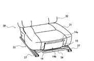
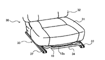
- FIG. 1 is a perspective view schematically showing an example of a state in which the in-vehicle heating device according to Embodiment 1 is attached to a vehicle seat.
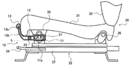
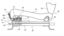
- FIG. 2 is a schematic diagram showing an example of the internal configuration of the in-vehicle heating device while showing the in-vehicle heating device shown in FIG. 1 from the side.
- FIG. 3 is a plan view, a side view, and a front view showing an example of the configuration of the in-vehicle heating device shown in FIG.
- FIG. 4 is a schematic diagram illustrating an example of a state in which the in-vehicle heating device illustrated in FIG. 1 is attached to the vehicle seat from below.
- FIG. 1 is a perspective view schematically showing an example of a state in which the in-vehicle heating device according to Embodiment 1 is attached to a vehicle seat.
- FIG. 2 is a schematic diagram showing an example of the internal configuration of the in-vehicle heating device while showing the in-vehi
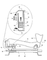
- FIG. 5 is a schematic diagram illustrating an example of the heating state of the user's feet by the in-vehicle heating device illustrated in FIG. 1.
- FIG. 6 is a perspective view schematically showing an example of a state in which the in-vehicle heating device according to Embodiment 2 is attached to a vehicle seat.
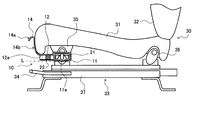
- FIG. 7 is a schematic diagram showing an example of an internal configuration of the in-vehicle heating device while showing the in-vehicle heating device shown in FIG. 6 from the side.
- FIG. 8 is a schematic diagram illustrating an example of a state of blowing hot air and sucking outside air by the in-vehicle heating device illustrated in FIG. 6.
- FIG. 6 is a perspective view schematically showing an example of a state in which the in-vehicle heating device according to Embodiment 2 is attached to a vehicle seat.
- FIG. 7 is a schematic diagram showing an example of an internal configuration of the in-vehicle heating device while showing the in-vehicle heating
- FIG. 9 is a schematic diagram illustrating an example of a state in which the in-vehicle heating device according to Embodiment 3 is attached to the vehicle seat from the side, and an example of the internal configuration of the in-vehicle heating device.
- FIG. 10 is a schematic diagram illustrating an example of an internal configuration of the in-vehicle heating device while the state where the in-vehicle heating device according to the fourth embodiment is attached to the vehicle seat is shown from the side.
- 11 is a plan view, a side view, and a front view showing an example of the configuration of the in-vehicle heating device shown in FIG. FIG.
- FIG. 12 is a perspective view schematically showing an example of a state in which the in-vehicle heating device according to Embodiment 5 is attached to a vehicle seat.
- FIG. 13 is a schematic diagram illustrating an example of an internal configuration of the in-vehicle heating device while showing the in-vehicle heating device illustrated in FIG. 12 from the side.
- FIG. 14 is a cross-sectional view schematically showing an example of a state in which the in-vehicle heating device according to Embodiment 6 is attached to a vehicle seat.
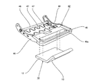
- FIG. 15 is a perspective view schematically showing a state where the in-vehicle heating device and the vehicle seat frame shown in FIG. 14 are separated.
- FIG. 16 is a perspective view showing the vehicle seat with the in-vehicle heating device shown in FIG. 14 attached.
- FIG. 17 is a cross-sectional view schematically showing an example of a state where the in-vehicle heating device according to Embodiment 7 is attached to a vehicle seat.
- FIG. 18 is a perspective view schematically showing a state in which the in-vehicle heating device and the vehicle seat frame shown in FIG. 17 are separated.
- FIG. 19 is a perspective view showing the vehicle seat with the in-vehicle heating device shown in FIG. 17 attached.
- FIG. 20 is a cross-sectional view schematically illustrating another example of a state where the in-vehicle heating device according to the seventh embodiment is attached to a seat.
- the in-vehicle heating device is provided in the lower front part of a seat cushion that is a seating portion of a vehicle seat, and is provided with a blower portion provided with a suction port for sucking outside air inside, and a heater inside.
- a hot air forming part that heats the air from the air blowing part to form hot air
- a blowout part that blows out the warm air from the hot air forming part to the front of the seat cushion.
- At least a part of the seat cushion is located in front of the seat cushion and serves as a front shield as a decorative member.
- the part located on the front surface in the blowing section may be configured to emit radiant heat by being heated by warm air.
- the air blowing unit and the hot air forming unit are located on the back side of the seat cushion, and the blowing unit circulates the hot air from the hot air forming unit. It is a hot air passage, and at the front end of the blowout part, the front of the seat cushion is provided with a blowout outlet that blows out hot air, and the front of the blowout part also serves as a front shield Also good.
- the air outlet may be provided obliquely downward on the front surface of the seat cushion.
- the in-vehicle heating device is located in front of the back side of the seat cushion, which is a seating portion of the vehicle seat, and is provided with a suction port for sucking outside air downward.
- the air blowing unit Located on the downstream side of the air blowing unit, the air blowing unit, and provided with a heater inside, a hot air forming unit that heats the air flow from the air blowing unit to form hot air, and a front side of the hot air forming unit And a blowing part that blows out the warm air from the warm air forming part to the front of the seat cushion, and the blowing part is configured to blow forward from a position above the suction port.
- the blowout part has a flat shape extending in the width direction of the seat cushion, and the blowout part has a thickness smaller than that of the warm air forming part, and the inside thereof is warm air. It is a warm air passage that circulates warm air from the forming part, and the front end of the blow-out part is located above the suction port and at the front surface of the seat cushion. There may be provided a blow-out port for blowing out the air.
- the air outlet may be provided obliquely downward on the front surface of the seat cushion.
- the air outlet may be configured as a slit-like opening that extends in the width direction of the seat cushion.
- the heater is provided in the warm air forming unit in a state intersecting the blowing direction from the blowing unit, and is located at a position behind the heater in the warm air forming unit. Is provided with a rectifying member for directing an air flow from the blower portion toward the heater.
- the blowout part spreads in the width direction in front of the seat cushion from above the suction port and blows out warm air. Therefore, it becomes possible to blow warm air suitably over the entire feet of the user sitting on the seat cushion.
- the in-vehicle heating device is located in front of the back side of the seat cushion, which is a seating portion of the vehicle seat, and sucks outside air into the hot air forming portion and sends it to the hot air forming portion, and more than the blowing portion.
- the hot air forming part that heats the air flow from the air blowing part to form hot air
- the downstream side of the hot air forming part the hot air from the hot air forming part is forward of the seat cushion
- the blower outlet is formed in a substantially arc shape that is rearward as the vehicle seat is viewed from above and the both end portions of the vehicle seat become both end sides.
- the blower outlet width may be wider than the heater width inside the warm air forming unit.
- the blown-out wind proceeds in a form of spreading radially toward the front as seen from above the seat. For this reason, it is possible to suitably blow warm air over the entire foot space wider than the seat width.
- FIG. 1 is a perspective view schematically showing an example of a state in which the in-vehicle heating device according to Embodiment 1 is attached to a vehicle seat.
- FIG. 2 is a schematic diagram showing an example of the internal configuration of the in-vehicle heating device while showing the in-vehicle heating device shown in FIG. 1 from the side.
- FIG. 3 is a plan view, a side view, and a front view showing an example of the configuration of the in-vehicle heating device shown in FIG.
- FIG. 4 is a schematic diagram showing an example of a state in which the in-vehicle heating device shown in FIG. 1 is attached to the vehicle seat from below.
- the in-vehicle heating device 10 according to the present embodiment is provided in front of the lower portion of the seat cushion 31 of the vehicle seat 30.
- the vehicle seat 30 shown in FIGS. 1 and 2 includes a seat cushion 31, a seat back 32, a slide device 33, and the like, and the seat cushion 31 serves as a seating portion. Becomes the backrest.
- the seat back 32 is attached to the seat cushion 31 via a reclining device (not shown), and the inclination angle of the seat back 32 can be changed.
- the slide device 33 includes an operation lever 34, and the position of the seat cushion 31 can be changed by a user (sitting person) operating it.
- the seat cushion 31 is attached to the slide device 33 via known brackets 35 and 36, and the in-vehicle heating device 10 according to the present embodiment is attached to the front bracket 35 so that the lower portion of the seat cushion 31 is installed. It is provided in the front.
- the in-vehicle heating device 10 includes a blower unit 11, a hot air forming unit 12, a blowing unit 13, and the like.
- the air blower 11 is located in front of the back side of the seat cushion 31 and is provided with a fan motor 21 therein, and a suction port 11a (bell mouth) for sucking outside air is provided facing downward.
- the shape of the air blowing unit 11 in the present embodiment is a substantially disk shape corresponding to the shape of the fan motor 21 housed therein, and a part of the air blowing unit 11 protrudes and communicates with the hot air forming unit 12.
- the specific structure of the ventilation part 11 is not specifically limited, For example, if the well-known fan motor 21 is provided in the well-known resin housing and the suction port 11a of a well-known shape is formed, it is the structure. Good.
- the suction inlet 11a should just be provided in the lower surface of the ventilation part 11, it is not limited to this, Even if it is provided in the side surface or front surface, etc. of the ventilation part 11, it faces downward. Just do it.
- the suction port 11a may be provided so as to face downward on the side surface or front surface of the air blowing unit 11 (surface in the vicinity of the hot air forming unit 12). By directing the suction port 11a downward, it is possible to reliably prevent the warm air from the blower outlet 13a from being sucked from the suction port 11a as it is.
- the suction port may be directed not only downward but also forward or sideward.
- FIG. 8 is a schematic diagram showing an example of a state of blowing hot air and sucking outside air by the in-vehicle heating device shown in FIG.
- the warm air that has returned to the blower unit 11 from the foot of the user 40 due to the formation of the reflux flows from the suction port 11a located below the blower unit 11. Will be sucked into.
- the air flow that warms the feet of the user 40 is sucked into the blower unit 11 and heated again by the hot air forming unit 12 and blown out from the blowing unit 14. Heating is possible.
- the guide plate front surface 14b is made of a material that is easy to radiate heat similarly to the first embodiment, the guide plate front surface 14b is heated by hot air as shown by an arrow R in FIG. Can be emitted.
- heating by warm air and heating by radiant heat from the heat radiation surface can be used in combination, so that the heating efficiency can be further improved.
- the reflux described in the first embodiment is performed by the user 40.
- Formed at the foot of As a result, it is possible to suitably blow warm air while effectively avoiding occurrence of temperature unevenness over the entire feet of the user 40 seated on the seat cushion 31.
- the warm air (refer to the block arrow F5 in FIG. 9) that has returned to the blower unit 11 from the foot of the user 40 due to the formation of the reflux is sucked into the interior from the lower suction port 15a of the integrated housing 15. It will be.
- the air flow that warms the feet of the user 40 is sucked into the interior, heated again by the heater 22, and blown out from the outlet 15b, so that efficient heating is possible. It becomes.
- FIG. 10 is a schematic diagram showing an example of the internal configuration of the in-vehicle heating device while showing the state where the in-vehicle heating device according to the fourth embodiment is attached to the vehicle seat from the side.
- 11 is a plan view, a side view, and a front view showing an example of the configuration of the in-vehicle heating device shown in FIG.
- the in-vehicle heating device 10 according to the fourth embodiment has basically the same configuration as the in-vehicle heating device 10 according to the first embodiment, but as shown in FIGS.
- mouth 11a differs.
- the suction guide member 27 is located below the blower unit 11 and the hot air forming unit 12 of the in-vehicle heating device 10, and has a rectangular cross section and a duct having only a front surface opened. It is a member.
- the suction guide member 27 is provided so as to connect the front of the in-vehicle heating device 10 (that is, the front of the seat cushion 31) and the suction port 11a below the blower unit 11. Thereby, the vehicle-mounted heating device 10 can easily suck the air flow (returned warm air) indicated by the block arrow F5 in FIG. 11 from the front of the seat cushion 31 from the suction port 11a, and thus heating efficiency can be improved. .
- the suction guide member 27 is not an essential component in the present invention, but can be appropriately provided in the in-vehicle heating device 10 according to the shape or installation status of the vehicle seat 30. Further, the specific shape of the suction guide member 27 is not limited to the duct shape as shown in FIGS. 10 and 11, and may be a wider duct shape, or the side surface may be opened in addition to the front surface. Alternatively, a configuration known in the field of introducing an air flow may be adopted.
- the in-vehicle heating device has a position above the suction port in front of the hot air forming unit.
- the hot air forming part also serves as the air blowing part, and a suction guide that introduces outside air from the front of the seat cushion to the air inlet below the air blowing part A member is provided.
- the in-vehicle heating apparatus may be configured in the same manner as any of the in-vehicle heating apparatuses according to the first to fourth embodiments except for the above characteristics.
- the configuration substantially corresponding to the blowout portion 13 or the blowout portion 14 is omitted, although the warm air from the blowout port 12a can be expanded in the width direction of the seat cushion 31,
- the substantial hot air blowing position (the hot air blowing position indicated by the block arrow F3 in FIG. 5 or FIG. 8) is lower than that in the first or second embodiment. Therefore, compared with the first or second embodiment, the reflux indicated by the block arrows F3, F4, and F5 in FIG. 5 may be relatively difficult to be formed.
- the air flow (returned warm air) indicated by the block arrow F5 can be easily formed, and as a result, it is possible to form a good reflux.
- the air outlet 12a is formed in a substantially arc shape that is rearward as the both ends of the vehicle seat 30 become both end sides when the vehicle seat 30 is viewed from above, the warm air of the air outlet 12a is It blows out while spreading radially in the width direction, spreads in a fan shape, and blows air to the entire foot space of the user.
- the blowout unit may be configured such that the front surface is heated by warm air and emits radiant heat.
- the in-vehicle heating device includes a blower portion provided at a lower portion of a seat cushion that is a seating portion of the seat, provided with a suction port for sucking outside air inside, and a heater inside.
- a warm air forming part that heats the air from the air blowing part to form warm air
- a blowout part that blows out the warm air from the warm air forming part to the front of the seat cushion, the front end of the blowout part, It arrange
- the blow-out unit may also serve as a front shield whose front surface is a decorative member.
- vehicle-mounted heating device may be configured in the same manner as the vehicle-mounted heating device of any one of the vehicle-mounted heating devices according to the first to fifth embodiments, except for the above characteristics.
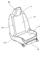
- the vehicle seat 30 includes a seat back 32, a seat cushion 31, and a headrest 41.
- the seat back 32 and the seat cushion 31 mount cushion pads (not shown) on the seat frame. It is covered with the skin material 32a and the skin material 31a.
- the seat back 32 is formed by placing a cushion pad (not shown) on the seat back frame and covering the cushion pad with the skin material 32a and supporting the back of the user from the rear. It is.
- the seat cushion 31 is configured such that a cushion pad 43 is placed on a seating frame 42 and is covered with a skin material 31a from above the cushion pad 43 to support the user from below.
- the rear end portion of the seating frame 42 is connected to the seat back frame via a reclining mechanism (not shown).
- the seating frame 42 is formed in a substantially rectangular frame, and includes a side frame 44 that is spaced in the left-right direction, and a plate-like frame that is laid on the front side (front end) of the side frame 44.
- the pan frame 45 is fixedly joined to the front side of the side frame 44, and the member pipe 46 is constructed and joined to the rear side of the side frame 44, and the side frame 44 is connected by the pan frame 45 and the member pipe 46.
- the in-vehicle heating device 10 includes a blower unit 11, a hot air forming unit 12, a blowout unit 13, and the like.
- the blower section 11 is fixed to the front position of the lower surface side of the pan frame 45 of the seat cushion 31 with a screw or the like, and the fan motor 21 is provided therein, and a suction port (bell mouth) for sucking outside air into the interior (FIG. (Not shown) is provided facing downward.
- the shape of the air blowing unit 11 in the present embodiment is a substantially disk shape corresponding to the shape of the fan motor 21 housed therein, and a part of the air blowing unit 11 protrudes and communicates with the hot air forming unit 12.
- the specific structure of the ventilation part 11 is not specifically limited, For example, what is necessary is just the structure by which the well-known fan motor 21 is provided in the well-known resin housing, and the suction port of a well-known shape is formed. .
- the suction port only needs to be provided on the lower surface of the air blowing unit 11, but the present invention is not limited to this, and even if it is provided on the side surface or the front surface of the air blowing unit 11, it may face downward. That's fine.
- a suction port may be provided so as to face downward on the side surface or front surface of the air blowing unit 11 (surface in the vicinity of being connected to the warm air forming unit 12).
- the rectifying member such as the rectifying plate described above is provided. It is used.
- the present invention is not limited to this, and if the air flow from the blower unit 11 can be sufficiently widened in the width direction by the type or shape of the blower unit 11 or the warm air forming unit 12, the flow is straightened.
- the member is not necessarily provided.
- the air outlet 13a is opened obliquely downward on the front surface of the seat cushion 31, and is configured as a slit-like opening that extends in the width direction in the present embodiment.
- the shape of the air outlet 13a is not limited to the slit shape, and may be a shape in which a large number of small openings are arranged in a line in the width direction, or about 2 to 3 slit-like openings. The shape arranged in parallel in the width direction may be sufficient.
- the fan motor 21 of the blower unit 11 When the in-vehicle heating device 10 starts operating by operating an operation unit (not shown) provided in a vehicle such as an automobile, the fan motor 21 of the blower unit 11 is rotated to form an air flow. As indicated by the block arrows, an air flow that flows from the blower unit 11 toward the hot air forming unit 12 is formed. This air flow flows so as to spread in the width direction of the hot air forming unit 12 from the blowing unit 11 by the rectifying plate. Since the warm air forming unit 12 includes the heater 22, the air flow is heated by the heater 22 to become warm air, and flows from the warm air forming unit 12 toward the blowing unit 13.
- the blow-out unit 13 is provided with a blow-out port 13 a that blows warm air above the suction port of the blower unit 11 and at a position that is the front surface of the seat cushion 31. And this blower outlet 13a becomes the slit-shaped opening which spreads in the width direction. Therefore, as shown by the block arrow in FIG. 14, the blow-out portion 13 can blow forward from the position above the suction port in a state where the warm air is widened in the width direction of the seat cushion 31.
- the blowing portion 13 is an air passage member having a thickness smaller than that of the hot air forming portion 12, the hot air from the hot air forming portion 12 is blown out from the air outlet 13a after passing through the narrow air passage. . Accordingly, it is possible to energize the warm air and blow it out at a high wind speed. Thereby, the flow of warm air blown out from the blower outlet 13a can exhibit favorable directivity toward the front lower side, and can make it easier to form a reflux. By forming the blowing part 13 thin, it can suppress that the blowing part 13 becomes obstructive at a user's step.
- the front surface of the blow-out portion 13 not only serves as a decoration for the vehicle seat, but is made of a material that easily radiates heat, and therefore can be heated by warm air to emit radiant heat.
- the blowing part 13 front surface becomes a heat radiation surface, in the front surface of the seat cushion 31, heating by warm air and heating by radiation heat from a heat radiation surface can be used together. As a result, the heating efficiency can be further improved.
- the blowing duct connecting the blowing portion 11 to the front surface of the seat cushion 31 is referred to as a front shield. May not be provided as a separate member. Therefore, it is avoided that heat energy is released from the duct to a region other than the front surface of the seat cushion 31. Therefore, even if the front surface of the blowing portion 13 is not a heat radiation surface, heat loss from the duct during heating can be suppressed, so that heating efficiency can be improved.
- the front surface of the blowout portion 13 also serves as a decorative member (front shield)
- a process such as formation of an opening in the front shield or connection of a duct to the front shield is performed. Is no longer necessary. Therefore, complication of the manufacturing process can be avoided.
- the blowing part 13 can be used as a front shield, the increase in the number of parts can be suppressed.
- the cushion pad 43 of the seat cushion 31 When the user sits on the vehicle seat 30, the cushion pad 43 of the seat cushion 31 is deformed by the weight of the user, and the deformed cushion pad 43 presses the blowing portion 13, and in a severe case, the blowing portion 13 is damaged. There is a risk of doing.
- the upper end of the blowing portion 13 is formed to be slightly lower than the pan frame 45, and therefore, when a heavy weight user is seated and the cushion pad 43 is greatly deformed. However, the deformation of the cushion pad 43 does not affect the blowing portion 13, and damage to the blowing portion 13 can be prevented.
- the front end of the blower outlet 13a is arrange
- the in-vehicle heating device according to the seventh embodiment is the same as the in-vehicle heating device according to any one of the first to sixth embodiments, except that a gap is formed between the blowing portion and the front side end of the seat cushion. A cover member covering the upper part of the gap is provided.
- the cover member may be fixed to both side surfaces of the seat cushion.
- a decorative member may be provided on both side surfaces of the seat cushion, and the cover member may be fixed to the decorative member.
- a core material made of resin and / or metal may be sewn into the seat cushion side edge of the cover member, and the core material may be fixed to both sides of the seat cushion.
- the blowing unit may be configured such that the front surface is heated by the warm air and emits radiant heat.
- the seat cushion side edge of the cover member may be bitten into the seat cushion.
- the surface of the cover member may be decorated similar to the decorative member.
- vehicle-mounted heating device may be configured in the same manner as any one of the vehicle-mounted heating devices according to the first to sixth embodiments, except for the above-described features.
- FIG. 17 is a cross-sectional view schematically showing an example of a state where the in-vehicle heating device according to Embodiment 7 is attached to a vehicle seat.
- FIG. 18 is a perspective view schematically showing a state in which the in-vehicle heating device and the vehicle seat frame shown in FIG. 17 are separated.
- FIG. 19 is a perspective view showing the vehicle seat with the in-vehicle heating device shown in FIG. 17 attached.
- the in-vehicle heating device according to the seventh embodiment has the same basic configuration as the in-vehicle heating device according to the sixth embodiment, but the front surface of the blowing portion 13 and the seat cushion 31. A difference is that a gap is formed between the side ends and a cover member 48 is provided to cover the gap. This will be specifically described below.
- the blowing portion 13 is disposed with a space between the front end portion of the seat cushion 31.
- the spacing between the blowing portion 13 and the seat cushion 31 is such that the seat cushion 31 does not contact the blowing portion 13 even if the seat cushion 31 is deformed when the user sits on the seat cushion 31 or puts a knee on the seat cushion 31. Is set.
- FIG. 17 illustrates a state where the seat cushion 31 is deformed by a two-dot chain line.
- a cover member 48 is disposed so as to cover the space between the blowing portion 13 and the seat cushion 31, and both ends of the cover member 48 are combined on both side surfaces of the seat cushion 31. It is fixed to a resinous decorative member 49.
- the cover member 48 is formed of a synthetic resin in the present embodiment, and the edge of the cover member 48 on the side of the seat cushion 31 is small.
- the cover member 48 is decorated so as to bite into the seat cushion 31 by about 1 to 5 mm. It is fixed to the member 49. When the user sits on the vehicle seat 30, the seat cushion 31 is deformed so as to slide relative to the fixed cover member 48, and no gap is generated between the cover member 48 and the seat cushion 31.
- the cushion pad 43 is accommodated in the seat cushion 31, and since the cushion pad 43 is made of a foam member, the dimensional tolerance of the seat cushion 31 is formed large.
- the cover member 48 is about 1 to 5 mm so that no gap is formed between the cover member 48 and the seat cushion 31 even when the seat cushion 31 having a large dimensional tolerance is deformed. The dimensional tolerance of the seat cushion 31 is absorbed by biting into the seat.
- the cover member 48 can have an uncomfortable appearance by applying the same decoration as the decorative member 49, and the appearance is not impaired. Further, since the cover member 48 comes into contact when the user is seated on the vehicle seat 30 and the cover member 48 may be damaged, PP (polypropylene) or PE is used in order to prevent the cover member 48 from being damaged. It is preferable to use a material having viscosity such as (polyethylene). Needless to say, materials such as PP or PE have good moldability and are suitable as appearance members.
- the cover member 48 is formed of synthetic resin, but the same material as the skin material 31a of the seat cushion 31 such as leather may be used.
- a linear or plate-like core made of a synthetic resin, metal, or the like is formed on the edge of the cover member 48 on the side of the seat cushion 31 and the edge of the in-vehicle heating device 10 on the side of the blowing portion 13. It is preferable that the cover member 48 is prevented from moving by sewing the material and fixing the core material to the decorative member 49 on both sides of the seat cushion 31. With this configuration, even when the user is seated on the vehicle seat 30 and the seat cushion 31 is deformed, it is possible to prevent a gap from being generated between the cover member 48 and the seat cushion 31.
- the cover member 48 is fixed to the decorative member 49.
- the decorative member 49 may be eliminated and the cover member 48 may be fixed to the seat cushion 31.
- the blowing portion 13 is disposed with a space between the seat cushion 31 and the space is changed by the seat cushion 31 being seated by the user. Since the seat cushion 31 is set to a size that does not contact the blowing portion 13, the blowing portion 13 is not damaged by the deformation of the seat cushion 31.
- the cover member 48 Since the space between the blowing portion 13 and the seat cushion 31 is covered by the cover member 48, the aesthetic appearance is not impaired, and dust or the like does not enter between the blowing portion 13 and the seat cushion 31.
- the distance between the blowing portion 13 and the seat cushion 31 is set to a size that does not allow the seat cushion 31 to contact the blowing portion 13 even if the seat cushion 31 is deformed by a user's seating or the like.
- the present invention is not limited to this.
- FIG. 20 is a cross-sectional view schematically showing another example of a state where the in-vehicle heating device according to the seventh embodiment is attached to a seat.
- a state where the seat cushion is deformed is illustrated by a two-point difference line.
- the seat cushion 31 may be set to a dimension that contacts the blowing portion 13 by deformation of the seat cushion 31, and the blowing portion 13 may be bent forward by deformation of the seat cushion 31.
- the present invention can be widely and suitably used in the field of heating devices attached to vehicle seats such as automobiles.
Landscapes
- Engineering & Computer Science (AREA)
- Aviation & Aerospace Engineering (AREA)
- Transportation (AREA)
- Mechanical Engineering (AREA)
- Chair Legs, Seat Parts, And Backrests (AREA)
- Air-Conditioning For Vehicles (AREA)
- Seats For Vehicles (AREA)
Abstract
Description
本実施の形態1に係る車載暖房装置は、車両用シートの着座部であるシートクッションの下部前方に設けられ、外気を内部に吸い込むための吸込口が設けられている送風部と、内部にヒータを備え、送風部からの送風を加熱して温風を形成する温風形成部と、温風形成部からの温風をシートクッションの前方に吹き出す吹出部と、を備え、当該吹出部は、少なくとも一部がシートクッションの前面に位置して装飾部材であるフロントシールドを兼ねている。
図1は、本実施の形態1に係る車載暖房装置を車両用シートに取り付けた状態の一例を模式的に示す斜視図である。図2は、図1に示す車載暖房装置を側方から示すとともに、車載暖房装置の内部構成の一例を示す模式図である。図3は、図1に示す車載暖房装置の構成の一例を示す平面図、側面図および正面図である。また、図4は、図1に示す車載暖房装置を車両用シートに取り付ける状態の一例を下方から示す模式図である。
次に、本実施の形態1に係る車載暖房装置10による使用者の足元を暖房する動作の一例について、図1~図4に加えて、図5を参照して具体的に説明する。
本実施の形態2に係る車載暖房装置は、実施の形態1に係る車載暖房装置において、温風形成部の前方には、吸込口よりも上方の位置に、温風を吹き出す吹出口が設けられ、吹出部は、吹出口の上縁から、シートクッションの前面に達する位置まで延伸する板状であり、その前面に吹出口からの温風を沿わせてシートクッションの前面にまで導く温風ガイド板として構成され、当該温風ガイド板がフロントシールドを兼ねている。
図6は、本実施の形態2に係る車載暖房装置を車両用シートに取り付けた状態の一例を模式的に示す斜視図である。図7は、図6に示す車載暖房装置を側方から示すとともに、車載暖房装置の内部構成の一例を示す模式図である。
次に、本実施の形態2に係る車載暖房装置10による使用者の足元を暖房する動作の一例について、図6および図7に加えて、図8を参照して具体的に説明する。
本実施の形態3に係る車載暖房装置は、実施の形態1又は2に係る車載暖房装置において、送風部、温風形成部および吹出部は、上下方向に一体化されて、シートクッションの前面に設けられており、その前面がフロントシールドを兼ねている。なお、本実施の形態3に係る車載暖房装置は、上記特徴以外は、実施の形態1又は2に係る車載暖房装置と同様に構成されていてもよい。
図9は、本実施の形態3に係る車載暖房装置を車両用シートに取り付けた状態の一例を側方から示すとともに、車載暖房装置の内部構成の一例を示す模式図である。
次に、本実施の形態3に係る車載暖房装置10による使用者の足元を暖房する動作の一例について、図9を参照して具体的に説明する。
本実施の形態4に係る車載暖房装置は、実施の形態1~3に係る車載暖房装置のいずれかの車載暖房装置において、吸込口に対して、外気の吸込方向をガイドする吸込用ガイド部材が設けられている。
本実施の形態5に係る車載暖房装置は、実施の形態1~4に係る車載暖房装置のいずれかの車載暖房装置において、温風形成部の前方には、吸込口よりも上方の位置に、温風を吹き出す吹出口が設けられることにより、当該温風形成部が吹出部を兼ねており、送風部の下側には、シートクッションの前方からの外気を、吸込口に導入する吸込用ガイド部材が設けられている。なお、本実施の形態5に係る車載暖房装置は、上記特徴以外は、実施の形態1~4に係る車載暖房装置のいずれかの車載暖房装置と同様に構成されていてもよい。
本実施の形態6に係る車載暖房装置は、実施の形態1~5に係る車載暖房装置のいずれかの車載暖房装置において、吹出部の前端を、シートクッションの前面側端部より後方となる位置に配置する。
図14は、本実施の形態6に係る車載用暖房装置を車両用シートに取り付けた状態の一例を模式的に示す断面図である。図15は、図14に示す車載用用暖房装置と車両用シートのフレームを分離した状態を模式的に示す斜視図である。図16は、図14に示す車載用暖房装置を装着した状態の車両用シートを示す斜視図である。
次に、車載暖房装置10による使用者の足元を暖房する動作の一例について説明する。
本実施の形態7に係る車載暖房装置は、実施の形態1~6に係る車載暖房装置のいずれかの車載暖房装置において、吹出部とシートクッションの前面側端部との間に間隙を形成し、間隙の上方を覆うカバー部材を設けている。
図17は、本実施の形態7に係る車載暖房装置を車両用シートに取り付けた状態の一例を模式的に示す断面図である。図18は、図17に示す車載暖房装置と車両用シートのフレームを分離した状態を模式的に示す斜視図である。図19は、図17に示す車載暖房装置を装着した状態の車両用シートを示す斜視図である。
ところで、使用者が車両用シート30に着座すると、シートクッション31のクッションパッド43が使用者の体重により変形し、変形したクッションパッド43が吹出部13を押圧して、著しい場合には吹出部13が破損するおそれがある。
11 送風部
11a 吸込口
12 温風形成部
12a 吹出口
13 吹出部(風路部材)
13a 吹出口
13b 吹出部前面(フロントシールド)
14 吹出部(板状部材、温風ガイド板)
14a ガイド板前縁
14b ガイド板前面(フロントシールド)
15 一体型筐体
15a 吸込口
15b 吹出口
15c 筐体前壁部(フロントシールド)
16 背面断熱材
21 ファンモータ
22 ヒータ
23 整流板
25 円筒状ファン
27 吸込用ガイド部材
30 車両用シート
31 シートクッション
33 スライド装置
34 操作レバー
37 スライドレール
40 使用者
42 着座フレーム
43 クッションパッド
44 サイドフレーム
45 パンフレーム
45a 前方折曲部
46 メンバーパイプ
47 スプリング
48 カバー部材
49 装飾部材
Claims (19)
- 車両用シートの着座部であるシートクッションの下部前方に設けられ、
外気を内部に吸い込むための吸込口が設けられている送風部と、
内部にヒータを備え、前記送風部からの送風を加熱して温風を形成する温風形成部と、
前記温風形成部からの前記温風を前記シートクッションの前方に吹き出す吹出部と、を備え、
当該吹出部は、少なくとも一部が前記シートクッションの前面に位置して装飾部材であるフロントシールドを兼ねていることを特徴とする、車載暖房装置。 - 前記吹出部における前記前面に位置する部位は、前記温風により加熱されて輻射熱を発するよう構成されていることを特徴とする、請求項1に記載の車載暖房装置。
- 前記送風部および前記温風形成部は、前記シートクッションの裏側に位置し、
前記吹出部は、その内部が、前記温風形成部からの前記温風を流通させる温風風路となっており、
前記吹出部の前端であって、前記シートクッションの前面となる位置には、前記温風を吹き出す吹出口が設けられており、
前記吹出部の前面が前記フロントシールドを兼ねていることを特徴とする、請求項1に記載の車載暖房装置。 - 前記温風形成部の前方には、前記吸込口よりも上方の位置に、前記温風を吹き出す吹出口が設けられ、
前記吹出部は、前記吹出口の上縁から、前記シートクッションの前面に達する位置まで延伸する板状であり、その前面に前記吹出口からの温風を沿わせて前記シートクッションの前面にまで導く温風ガイド板として構成され、
当該温風ガイド板が前記フロントシールドを兼ねていることを特徴とする、請求項1に記載の車載暖房装置。 - 前記送風部、前記温風形成部および前記吹出部は、上下方向に一体化されて、前記シートクッションの前面に設けられており、
その前面が前記フロントシールドを兼ねていることを特徴とする、請求項1に記載の車載暖房装置。 - 前記吸込口が下側に向いて設けられており、
前記吹出部は、前記温風形成部の前側に位置し、前記吸込口よりも上方となる位置から、前方に吹き出すよう構成されていることを特徴とする、請求項1に記載の車載暖房装置。 - 前記吹出部は、前記シートクッションの幅方向に広がる平坦形状であり、
前記吹出部は、前記温風形成部よりも厚みが小さく、その内部が、前記温風形成部からの前記温風を流通させる温風風路となっており、
前記吹出部の前端は、前記吸込口よりも上方で、かつ、前記シートクッションの前面となる位置に配置され、この前端に、前記温風を吹き出す吹出口が設けられていることを特徴とする、請求項6に記載の車載暖房装置。 - 前記温風形成部の前方には、前記吸込口よりも上方の位置に、前記温風を吹き出す吹出口が設けられ、
前記吹出部は、前記吹出口の上縁から、前記シートクッションの前面に達する位置まで延伸する板状であり、その前面に前記吹出口からの温風を沿わせて前記シートクッションの前面にまで導く温風ガイド板として構成されていることを特徴とする、請求項6に記載の車載暖房装置。 - 前記温風形成部の前方には、前記吸込口よりも上方の位置に、前記温風を吹き出す吹出口が設けられることにより、当該温風形成部が前記吹出部を兼ねており、
前記送風部の下側には、前記シートクッションの前方からの外気を、前記吸込口に導入する吸込用ガイド部材が設けられていることを特徴とする、請求項6に記載の車載暖房装置。 - 前記ヒータは、前記送風部からの送風方向に交差する状態で、前記温風形成部内に設けられ、
前記温風形成部における前記ヒータよりも後側の位置には、前記送風部から前記ヒータに向けて前記空気流を指向させる整流部材が設けられていることを特徴とする、請求項6に記載の車載暖房装置。 - 前記吹出口は、前記車両用シートを上方から見て、前記車両用シート両端部分が両端側になるに従って後方になる略円弧状に形成されていることを特徴とする、請求項1に記載の車載暖房装置。
- 前記温風形成部内部のヒータ幅よりも、前記吹出口幅の方が広いことを特徴とする、請求項11に記載の車載暖房装置。
- 前記吹出部の前端を、前記シートクッションの前面側端部より後方となる位置に配置することを特徴とする、請求項1に記載の車載暖房装置。
- 前記吹出部は、前面が前記温風により加熱されて輻射熱を発するように構成したことを特徴とする、請求項13に記載の車載暖房装置。
- 前記吹出部と前記シートクッションの前面側端部との間に間隙を形成し、前記間隙の上方を覆うカバー部材を設けたことを特徴とする、請求項1に記載の車載暖房装置。
- 前記カバー部材を前記シートクッションの両側面に固定したことを特徴とする、請求項15に記載の車載暖房装置。
- 前記シートクッションの両側面に装飾部材を配設し、前記カバー部材を前記装飾部材に固定したことを特徴とする、請求項15に記載の車載暖房装置。
- 前記カバー部材の前記シートクッション側端縁に樹脂及び/又は金属からなる芯材を縫い込み、前記芯材を前記シートクッション両側面に固定することを特徴とする、請求項15に記載の車載暖房装置。
- 前記吹出部は、前面が前記温風により加熱されて輻射熱を発するように構成したことを特徴とする、請求項15に記載の車載暖房装置。
Priority Applications (5)
| Application Number | Priority Date | Filing Date | Title |
|---|---|---|---|
| EP13863545.3A EP2933135B1 (en) | 2012-12-14 | 2013-11-29 | Vehicle-mounted heater device |
| CN201380062445.6A CN104837676B (zh) | 2012-12-14 | 2013-11-29 | 车载制热装置 |
| US14/650,800 US9649960B2 (en) | 2012-12-14 | 2013-11-29 | In-vehicle heating device |
| JP2014551870A JP5824675B2 (ja) | 2012-12-14 | 2013-11-29 | 車載暖房装置 |
| US15/482,046 US20170210260A1 (en) | 2012-12-14 | 2017-04-07 | In-vehicle heating device |
Applications Claiming Priority (10)
| Application Number | Priority Date | Filing Date | Title |
|---|---|---|---|
| JP2012-273800 | 2012-12-14 | ||
| JP2012273800 | 2012-12-14 | ||
| JP2012-273801 | 2012-12-14 | ||
| JP2012273801 | 2012-12-14 | ||
| JP2013020152 | 2013-02-05 | ||
| JP2013-020152 | 2013-02-05 | ||
| JP2013038387 | 2013-02-28 | ||
| JP2013-038388 | 2013-02-28 | ||
| JP2013038388 | 2013-02-28 | ||
| JP2013-038387 | 2013-02-28 |
Related Child Applications (2)
| Application Number | Title | Priority Date | Filing Date |
|---|---|---|---|
| US14/650,800 A-371-Of-International US9649960B2 (en) | 2012-12-14 | 2013-11-29 | In-vehicle heating device |
| US15/482,046 Division US20170210260A1 (en) | 2012-12-14 | 2017-04-07 | In-vehicle heating device |
Publications (1)
| Publication Number | Publication Date |
|---|---|
| WO2014091705A1 true WO2014091705A1 (ja) | 2014-06-19 |
Family
ID=50934013
Family Applications (1)
| Application Number | Title | Priority Date | Filing Date |
|---|---|---|---|
| PCT/JP2013/007029 Ceased WO2014091705A1 (ja) | 2012-12-14 | 2013-11-29 | 車載暖房装置 |
Country Status (5)
| Country | Link |
|---|---|
| US (2) | US9649960B2 (ja) |
| EP (1) | EP2933135B1 (ja) |
| JP (2) | JP5824675B2 (ja) |
| CN (1) | CN104837676B (ja) |
| WO (1) | WO2014091705A1 (ja) |
Cited By (4)
| Publication number | Priority date | Publication date | Assignee | Title |
|---|---|---|---|---|
| JP2016168957A (ja) * | 2015-03-13 | 2016-09-23 | トヨタ自動車株式会社 | 車両用シート |
| WO2018003307A1 (ja) * | 2016-06-30 | 2018-01-04 | 株式会社デンソー | シート送風装置 |
| US20180134194A1 (en) * | 2015-08-04 | 2018-05-17 | Panasonic Intellectual Property Management Co., Ltd. | Insulating sheet, and backrest seat and cold weather garment employing the same |
| WO2019116597A1 (ja) * | 2017-12-12 | 2019-06-20 | シャープ株式会社 | 椅子用送風ユニットおよび送風機能付き椅子 |
Families Citing this family (12)
| Publication number | Priority date | Publication date | Assignee | Title |
|---|---|---|---|---|
| EP3017998B1 (en) * | 2013-07-02 | 2017-04-26 | Panasonic Intellectual Property Management Co., Ltd. | Vehicle heating system |
| WO2015030195A1 (ja) * | 2013-08-30 | 2015-03-05 | テイ・エス テック株式会社 | シート |
| US20170129375A1 (en) * | 2014-06-12 | 2017-05-11 | Gentherm Automotive Systems (China) Ltd. | Ventilation device for supplying air to a passenger on a vehicle seat |
| US10023084B2 (en) * | 2015-07-15 | 2018-07-17 | Gentherm Inc. | Vehicle seat with slidable air coupling |
| CN108698473B (zh) * | 2016-02-23 | 2021-09-07 | 株式会社电装 | 座位空调装置 |
| US9789796B1 (en) * | 2016-04-13 | 2017-10-17 | GM Global Technology Operations LLC | Seat with a cylindrical ventilation fan |
| JP2019084295A (ja) * | 2017-11-10 | 2019-06-06 | トヨタ紡織株式会社 | 空調シート |
| JP7368691B2 (ja) * | 2019-03-14 | 2023-10-25 | テイ・エス テック株式会社 | 乗り物用シート |
| JP2021075187A (ja) * | 2019-11-11 | 2021-05-20 | 日本発條株式会社 | 車両用シート |
| CN115427241B (zh) * | 2020-04-14 | 2026-02-13 | 翰昂汽车零部件有限公司 | 加热单元以及包括该加热单元的车辆加热装置 |
| KR102898370B1 (ko) * | 2020-06-22 | 2025-12-09 | 현대자동차주식회사 | 차량용 난방 장치 |
| WO2022091743A1 (ja) * | 2020-10-30 | 2022-05-05 | パナソニックIpマネジメント株式会社 | 車両用シート空調装置 |
Citations (3)
| Publication number | Priority date | Publication date | Assignee | Title |
|---|---|---|---|---|
| JP2011126329A (ja) * | 2009-12-15 | 2011-06-30 | Mitsubishi Fuso Truck & Bus Corp | バス車両の暖房装置 |
| JP2011254882A (ja) | 2010-06-07 | 2011-12-22 | Toyota Boshoku Corp | 乗物用シート |
| JP2012183154A (ja) * | 2011-03-04 | 2012-09-27 | Toyota Boshoku Corp | 車両用シート |
Family Cites Families (14)
| Publication number | Priority date | Publication date | Assignee | Title |
|---|---|---|---|---|
| JPS60150709A (ja) * | 1984-01-18 | 1985-08-08 | トヨタ自動車株式会社 | 温風式シ−トヒ−タ |
| JP4224939B2 (ja) * | 2000-03-31 | 2009-02-18 | 株式会社デンソー | 車両用空調装置 |
| WO2004082990A1 (de) * | 2003-03-17 | 2004-09-30 | W.E.T. Automotive Systems Ag | Klimatisierungsvorrichtung für einen fahrgastraum eines fahrzeuges |
| JP2004283403A (ja) * | 2003-03-24 | 2004-10-14 | Denso Corp | シート空調装置および車両用シート空調装置 |
| DE602005025089D1 (de) | 2004-03-09 | 2011-01-13 | Panasonic Corp | Klimatisierter sitz und selbigen verwendende klimaanlage |
| JP2005253490A (ja) * | 2004-03-09 | 2005-09-22 | Matsushita Electric Ind Co Ltd | 空調座席装置 |
| JP2010242601A (ja) | 2009-04-03 | 2010-10-28 | Panasonic Corp | 遠心式送風機及び自動車用シート |
| CN102310793B (zh) * | 2010-10-16 | 2013-07-31 | 吴海荣 | 一种冷热式汽车座垫 |
| KR101230672B1 (ko) * | 2011-01-17 | 2013-02-07 | 갑을오토텍(주) | 차량 시트용 냉난방장치 |
| CN202319988U (zh) * | 2011-11-16 | 2012-07-11 | 上海通用汽车有限公司 | 一种汽车座椅通风装置 |
| JP6044506B2 (ja) * | 2013-10-25 | 2016-12-14 | 株式会社デンソー | 車両用シート空調装置 |
| JP6201632B2 (ja) * | 2013-10-25 | 2017-09-27 | 株式会社デンソー | 車両用シート空調装置 |
| EP3135532B1 (en) * | 2014-10-07 | 2017-09-20 | C.R.F. Società Consortile per Azioni | Motor vehicle having a seat provided with a system for supplying conditioned air |
| US10065544B2 (en) * | 2015-05-07 | 2018-09-04 | Faurecia Automotive Seating, Llc | Vehicle seat with thermal device |
-
2013
- 2013-11-29 CN CN201380062445.6A patent/CN104837676B/zh active Active
- 2013-11-29 JP JP2014551870A patent/JP5824675B2/ja not_active Expired - Fee Related
- 2013-11-29 EP EP13863545.3A patent/EP2933135B1/en active Active
- 2013-11-29 US US14/650,800 patent/US9649960B2/en active Active
- 2013-11-29 WO PCT/JP2013/007029 patent/WO2014091705A1/ja not_active Ceased
-
2015
- 2015-05-12 JP JP2015097138A patent/JP6296395B2/ja not_active Expired - Fee Related
-
2017
- 2017-04-07 US US15/482,046 patent/US20170210260A1/en not_active Abandoned
Patent Citations (3)
| Publication number | Priority date | Publication date | Assignee | Title |
|---|---|---|---|---|
| JP2011126329A (ja) * | 2009-12-15 | 2011-06-30 | Mitsubishi Fuso Truck & Bus Corp | バス車両の暖房装置 |
| JP2011254882A (ja) | 2010-06-07 | 2011-12-22 | Toyota Boshoku Corp | 乗物用シート |
| JP2012183154A (ja) * | 2011-03-04 | 2012-09-27 | Toyota Boshoku Corp | 車両用シート |
Cited By (6)
| Publication number | Priority date | Publication date | Assignee | Title |
|---|---|---|---|---|
| JP2016168957A (ja) * | 2015-03-13 | 2016-09-23 | トヨタ自動車株式会社 | 車両用シート |
| US20180134194A1 (en) * | 2015-08-04 | 2018-05-17 | Panasonic Intellectual Property Management Co., Ltd. | Insulating sheet, and backrest seat and cold weather garment employing the same |
| US11040643B2 (en) * | 2015-08-04 | 2021-06-22 | Panasonic Intellectual Property Management Co., Ltd. | Insulating sheet, and backrest seat and cold weather garment employing the same |
| WO2018003307A1 (ja) * | 2016-06-30 | 2018-01-04 | 株式会社デンソー | シート送風装置 |
| JPWO2018003307A1 (ja) * | 2016-06-30 | 2018-11-22 | 株式会社デンソー | シート送風装置 |
| WO2019116597A1 (ja) * | 2017-12-12 | 2019-06-20 | シャープ株式会社 | 椅子用送風ユニットおよび送風機能付き椅子 |
Also Published As
| Publication number | Publication date |
|---|---|
| EP2933135A4 (en) | 2016-01-27 |
| EP2933135A1 (en) | 2015-10-21 |
| JP6296395B2 (ja) | 2018-03-20 |
| JPWO2014091705A1 (ja) | 2017-01-05 |
| US20150329028A1 (en) | 2015-11-19 |
| CN104837676B (zh) | 2016-12-21 |
| JP2015171890A (ja) | 2015-10-01 |
| CN104837676A (zh) | 2015-08-12 |
| JP5824675B2 (ja) | 2015-11-25 |
| EP2933135B1 (en) | 2020-04-15 |
| US20170210260A1 (en) | 2017-07-27 |
| US9649960B2 (en) | 2017-05-16 |
Similar Documents
| Publication | Publication Date | Title |
|---|---|---|
| JP6296395B2 (ja) | 車載暖房装置 | |
| JP6536174B2 (ja) | 乗物用シート | |
| US7784863B2 (en) | Vehicle seat | |
| JP6520392B2 (ja) | 乗物用シート | |
| KR101673807B1 (ko) | 워머가 구비된 시트 | |
| CN105599651B (zh) | 用于车辆的空调装置 | |
| US20160144754A1 (en) | Vehicle seat with a ventilating device | |
| JP2011254882A (ja) | 乗物用シート | |
| JP2019162928A (ja) | 車両用空調装置 | |
| CN104169127B (zh) | 交通工具用供暖装置及带供暖的交通工具用座椅 | |
| WO2015001756A1 (ja) | 乗物用暖房システム | |
| JP6128373B2 (ja) | 車両用暖房装置及び暖房付きインストルメントパネルモジュール | |
| JP7069679B2 (ja) | 気流制御装置 | |
| US20240239253A1 (en) | Ventilated seat | |
| JP2022006936A (ja) | シートカバー | |
| JP2003252036A (ja) | 送風式温調シート | |
| KR100778593B1 (ko) | 자동차용 냉난방 통풍시트의 열전소자 장착구조 | |
| JP2014148283A (ja) | 乗り物用シート | |
| KR101636391B1 (ko) | 차량용 시트 | |
| JP2013086521A (ja) | 車両用シート | |
| JP2011126329A (ja) | バス車両の暖房装置 | |
| KR20180116017A (ko) | 차량 시트의 헤드레스트에 탈부착가능하게 장착된 냉난방장치 | |
| JP2023107235A (ja) | 乗物用シート | |
| JP2006205992A (ja) | 車両用暖房装置 | |
| JP6221955B2 (ja) | 乗物用シート |
Legal Events
| Date | Code | Title | Description |
|---|---|---|---|
| 121 | Ep: the epo has been informed by wipo that ep was designated in this application |
Ref document number: 13863545 Country of ref document: EP Kind code of ref document: A1 |
|
| ENP | Entry into the national phase |
Ref document number: 2014551870 Country of ref document: JP Kind code of ref document: A |
|
| WWE | Wipo information: entry into national phase |
Ref document number: 14650800 Country of ref document: US |
|
| NENP | Non-entry into the national phase |
Ref country code: DE |
|
| WWE | Wipo information: entry into national phase |
Ref document number: 2013863545 Country of ref document: EP |