WO2014091794A1 - 船外機の始動制御装置、船外機の始動制御方法およびプログラム - Google Patents
船外機の始動制御装置、船外機の始動制御方法およびプログラム Download PDFInfo
- Publication number
- WO2014091794A1 WO2014091794A1 PCT/JP2013/071901 JP2013071901W WO2014091794A1 WO 2014091794 A1 WO2014091794 A1 WO 2014091794A1 JP 2013071901 W JP2013071901 W JP 2013071901W WO 2014091794 A1 WO2014091794 A1 WO 2014091794A1
- Authority
- WO
- WIPO (PCT)
- Prior art keywords
- outboard motor
- instruction
- authentication
- instructing
- switch
- Prior art date
- Legal status (The legal status is an assumption and is not a legal conclusion. Google has not performed a legal analysis and makes no representation as to the accuracy of the status listed.)
- Ceased
Links
Images

Classifications
-
- F—MECHANICAL ENGINEERING; LIGHTING; HEATING; WEAPONS; BLASTING
- F02—COMBUSTION ENGINES; HOT-GAS OR COMBUSTION-PRODUCT ENGINE PLANTS
- F02N—STARTING OF COMBUSTION ENGINES; STARTING AIDS FOR SUCH ENGINES, NOT OTHERWISE PROVIDED FOR
- F02N11/00—Starting of engines by means of electric motors
- F02N11/08—Circuits specially adapted for starting of engines
- F02N11/0803—Circuits specially adapted for starting of engines characterised by means for initiating engine start or stop
- F02N11/0807—Remote means
-
- B—PERFORMING OPERATIONS; TRANSPORTING
- B63—SHIPS OR OTHER WATERBORNE VESSELS; RELATED EQUIPMENT
- B63J—AUXILIARIES ON VESSELS
- B63J99/00—Subject matter not provided for in other groups of this subclass
-
- B—PERFORMING OPERATIONS; TRANSPORTING
- B63—SHIPS OR OTHER WATERBORNE VESSELS; RELATED EQUIPMENT
- B63H—MARINE PROPULSION OR STEERING
- B63H20/00—Outboard propulsion units, e.g. outboard motors or Z-drives; Arrangements thereof on vessels
-
- B—PERFORMING OPERATIONS; TRANSPORTING
- B63—SHIPS OR OTHER WATERBORNE VESSELS; RELATED EQUIPMENT
- B63H—MARINE PROPULSION OR STEERING
- B63H21/00—Use of propulsion power plant or units on vessels
- B63H21/21—Control means for engine or transmission, specially adapted for use on marine vessels
-
- F—MECHANICAL ENGINEERING; LIGHTING; HEATING; WEAPONS; BLASTING
- F02—COMBUSTION ENGINES; HOT-GAS OR COMBUSTION-PRODUCT ENGINE PLANTS
- F02N—STARTING OF COMBUSTION ENGINES; STARTING AIDS FOR SUCH ENGINES, NOT OTHERWISE PROVIDED FOR
- F02N11/00—Starting of engines by means of electric motors
- F02N11/08—Circuits specially adapted for starting of engines
- F02N11/0803—Circuits specially adapted for starting of engines characterised by means for initiating engine start or stop
-
- B—PERFORMING OPERATIONS; TRANSPORTING
- B63—SHIPS OR OTHER WATERBORNE VESSELS; RELATED EQUIPMENT
- B63B—SHIPS OR OTHER WATERBORNE VESSELS; EQUIPMENT FOR SHIPPING
- B63B17/00—Vessels parts, details, or accessories, not otherwise provided for
- B63B2017/0009—Methods or devices specially adapted for preventing theft, or unauthorized use of vessels, or parts or accessories thereof, other than by using locks
-
- B—PERFORMING OPERATIONS; TRANSPORTING
- B63—SHIPS OR OTHER WATERBORNE VESSELS; RELATED EQUIPMENT
- B63H—MARINE PROPULSION OR STEERING
- B63H20/00—Outboard propulsion units, e.g. outboard motors or Z-drives; Arrangements thereof on vessels
- B63H20/14—Transmission between propulsion power unit and propulsion element
-
- B—PERFORMING OPERATIONS; TRANSPORTING
- B63—SHIPS OR OTHER WATERBORNE VESSELS; RELATED EQUIPMENT
- B63H—MARINE PROPULSION OR STEERING
- B63H21/00—Use of propulsion power plant or units on vessels
- B63H21/21—Control means for engine or transmission, specially adapted for use on marine vessels
- B63H21/213—Levers or the like for controlling the engine or the transmission, e.g. single hand control levers
-
- F—MECHANICAL ENGINEERING; LIGHTING; HEATING; WEAPONS; BLASTING
- F02—COMBUSTION ENGINES; HOT-GAS OR COMBUSTION-PRODUCT ENGINE PLANTS
- F02B—INTERNAL-COMBUSTION PISTON ENGINES; COMBUSTION ENGINES IN GENERAL
- F02B61/00—Adaptations of engines for driving vehicles or for driving propellers; Combinations of engines with gearing
- F02B61/04—Adaptations of engines for driving vehicles or for driving propellers; Combinations of engines with gearing for driving propellers
- F02B61/045—Adaptations of engines for driving vehicles or for driving propellers; Combinations of engines with gearing for driving propellers for marine engines
-
- F—MECHANICAL ENGINEERING; LIGHTING; HEATING; WEAPONS; BLASTING
- F02—COMBUSTION ENGINES; HOT-GAS OR COMBUSTION-PRODUCT ENGINE PLANTS
- F02P—IGNITION, OTHER THAN COMPRESSION IGNITION, FOR INTERNAL-COMBUSTION ENGINES; TESTING OF IGNITION TIMING IN COMPRESSION-IGNITION ENGINES
- F02P11/00—Safety means for electric spark ignition, not otherwise provided for
Definitions
- the present invention relates to an outboard motor start control device, an outboard motor start control method and program.
- it is preferably used when unlocking and executing security of an outboard motor using an electronic key.
- an ignition switch installed in the outboard motor main body or a steering wheel is used. Specifically, by inserting a key into the ignition switch and rotating the ignition switch stepwise, after the ignition is turned on, the start switch is turned on and the outboard motor is started.
- the first depression of the portable device is authenticated by using a single switch, the steering lock is unlocked, and the second depression of the portable device is again authenticated and the system is turned on.
- the engine is started by the third press.
- the user does not necessarily want to start the engine, and it is also assumed that the user wants to turn off the system without starting the engine from the system on state. In this case, for example, in a four-wheeled vehicle or the like, it can be considered to switch between starting the engine or turning off the system depending on whether or not the brake pedal is depressed when pressing one switch.
- the present invention has been made in view of the above-described problems, and it is an outboard motor system according to the present invention, even if the security of the outboard motor is canceled and executed according to the authentication of the portable machine.
- An object of the present invention is to enable transition to a state (ignition off state) in which power supply to the outboard motor is stopped without starting the outboard motor from a state where power is supplied (ignition on state). .
- the outboard motor start control device is an outboard motor start control device that controls the start and stop of the outboard motor according to an instruction from the boat operator, and the first switch is operated by the boat operator.
- the electric power supplied to the outboard motor Power supply instructing means for instructing supply, security release instructing means for instructing release of security of the outboard motor when authentication of the portable device is successful by the authentication means, and instructions of the power supply instructing means When the first switch is operated by the operator while the electric power is supplied to the outboard motor according to the condition and the security of the outboard motor is released according to the instruction of the security release instructing means To the emergency
- the determining means determines whether or not the switch is on, the start instructing means for instructing the start of the outboard motor when it is determined by the determining means that the emergency switch is not on, and the determining means And a stop instructing unit configured to instruct a stop
- the outboard motor start control method is an outboard motor start control method for controlling start and stop of the outboard motor in accordance with an instruction from the operator, wherein the first switch is operated by the operator.
- the electric power supplied to the outboard motor A power supply instruction step of instructing supply, a security release instruction step of instructing cancellation of the security of the outboard motor when authentication of the portable device is succeeded by the authentication step, and an instruction of the power supply instruction step
- the first switch is used by the operator If the emergency switch is determined to be on in the determination step, the start instruction step for instructing the start of the outboard motor if determined that the emergency switch is not on.
- the program according to the present invention is a program for controlling the start and stop of the outboard motor in response to an instruction from the ship operator, and the first switch is operated by the ship operator via the communication unit.
- the outboard motor is instructed to release the security of the outboard motor according to the instruction of the security release instruction step and the power supply instruction step.
- FIG. 1 is a perspective view of a ship as viewed obliquely from the rear.
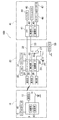
- FIG. 2 is a block diagram showing the configuration of the outboard motor system.
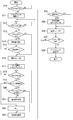
- FIG. 3 is a flowchart showing processing of the outboard motor start control device.
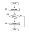
- FIG. 4 is a flowchart showing processing of the outboard motor start control device.
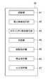
- FIG. 5 is a diagram showing a functional configuration of the start control device.
- FIG. 1 is a perspective view of a ship as viewed obliquely from the rear.
- an outboard motor 40 having a propeller 48 is attached to a transom 2 a located at the rear of the hull 2 of the ship 1 via a bracket device.
- a boat maneuvering room 4 is provided substantially at the center of the hull 2.
- the maneuvering room 4 is provided with a steering handle 5 and a remote control lever 6 for steering the ship 1.
- the boat maneuvering room 4 is also provided with a start control device 20 for the outboard motor 40.
- the start control device 20 controls the start and stop of the outboard motor 40 and controls the release and execution of the security of the outboard motor 40.
- the start control device 20 performs wireless communication with the portable device 10, which will be described later, carried by the boat operator via the communication unit 24.
- the start control device 20 performs authentication based on the encryption code received from the portable device 10, and instructs the outboard motor 40 to release security or execute security according to the authentication result. Further, the start control device 20 starts the authentication and instructs the outboard motor 40 to start or stop in response to the operation of the start switch 30 by the operator. Furthermore, the start control device 20 instructs the outboard motor 40 to stop in response to the operation of the emergency SW 31 by the operator in an emergency.
- a plurality of communication units 24 are installed in the bow, stern, etc. in addition to the maneuvering room 4. That is, the plurality of communication units 24 are installed so that communication with the start control device 20 becomes possible if the operator who carries the portable machine 10 is present in the hull 2. Therefore, if the operator who carries the portable machine 10 is absent in the boat maneuvering room 4 and is present in the hull 2, even if another person operates the start SW 30, the portable machine 10 and Authentication is possible. Therefore, even the other person can steer the outboard motor 40.
- FIG. 2 is a block diagram showing the configuration of the outboard motor system 100. As shown in FIG. In FIG. 2, the same components as in FIG. 1 are given the same reference numerals. Hereinafter, the specific configuration of the outboard motor system 100 will be described.
- the outboard motor system 100 includes a portable machine 10, a start control device 20, and an outboard motor 40.
- the portable device 10 is a so-called electronic key which can be carried by the operator.
- the portable device 10 can wirelessly communicate with the start control device 20.
- the portable device 10 includes a control unit 11, a storage unit 12, a communication unit 13, a battery 14, an up switch 15, a down switch 16, and the like.
- the control unit 11 controls the entire portable device 10.
- the control unit 11 transmits the encryption code stored in the storage unit 12 to the start control device 20 in response to an instruction from the start control device 20.
- the storage unit 12 stores a program executed by the control unit 11, an encryption code, and the like.
- the communication unit 13 is, for example, an antenna, and transmits and receives data to and from the communication unit 24 of the start control device 20.
- the battery 14 supplies power to the control unit 11 and the like.
- the up SW 15 and the down SW 16 are switches used by the operator to adjust the output of the outboard motor 40 when, for example, the ship 1 is to be docked. Specifically, the up SW 15 and the down SW 16 are switches used by the operator to adjust the engine speed of the outboard motor 40 within the low speed range.
- the up switch 15 is a switch that is pressed when the operator wants to increase the engine speed within the low speed range.
- the down switch 16 is a switch that is pressed when the operator wants to reduce the engine speed within the low speed range.
- the start control device 20 can communicate with the portable device 10 and the outboard motor 40.
- the start control device 20 includes a smart unit 21, a communication unit 24, a display unit 25, a notification unit 26, a power supply relay 27, a battery SW 28, a battery 29, a start switch 30, an emergency switch 31, and the like.
- the smart unit 21 also constitutes a so-called computer including the control unit 22 and the storage unit 23.
- the control unit 22 controls the entire start control device 20.
- the control unit 22 performs authentication based on the encryption code received from the portable device 10, and instructs the outboard motor 40 to release the security or execute the security according to the authentication result.
- the control unit 22 also instructs the outboard motor 40 to start and stop in response to the operation of the start switch 30.
- the storage unit 23 stores a program executed by the control unit 22, an encryption code for collation (hereinafter referred to as a collation code), and the like.
- the communication unit 24 is, for example, an antenna, and transmits and receives data to and from the communication unit 13 of the portable device 10.
- the display unit 25 is, for example, a liquid crystal monitor, and displays the driving state of the outboard motor 40 and the like.
- the notification unit 26 is, for example, a buzzer or an LED, and notifies the operator of the vessel using sound or light.
- the power supply relay 27 is disposed in the middle of the power supply cable 33 connecting the battery 29 and the outboard motor 40.
- the power supply relay 27 is controlled by the control unit 22 to turn on and off.
- the battery SW 28 is disposed between the battery 29 and the smart unit 21. By turning on the battery SW 28 by the operator, power is supplied from the battery 29 to the smart unit 21. In addition, when the operator turns off the battery SW 28, the supply of power from the battery 29 to the smart unit 21 is stopped.
- the battery 29 also supplies power to the start control device 20, the outboard motor 40 and an accessory 50 described later.
- the start switch 30 is, for example, a push switch as a first switch.
- the start switch 30 is a switch that is depressed when the operator starts or stops the outboard motor 40.
- the emergency SW (emergency switch) 31 is a switch for stopping the outboard motor 40 in an emergency, and the pulling member can be inserted and removed.
- the emergency switch 31 is off, and the outboard motor 40 can be driven continuously.
- the emergency SW 31 is turned on, and the control unit 22 stops the outboard motor 40.
- the pulling member is connected to the operator via a cord. Therefore, for example, when the operator falls on the water, the pulling member is pulled out of the emergency SW 31, so the emergency SW 31 is turned on and the outboard motor 40 is stopped.
- the outboard motor 40 can communicate with the start control device 20 via the communication cable 32.
- the outboard motor 40 of the present embodiment will be described for the case where the propeller 48 is rotated by the engine. However, the present invention is not limited to this case.
- the outboard motor 40 includes an ECU 41, an injector 44, an ignition coil 45, a starter relay 46, a starter motor 47, and the like. Further, the ECU 41 is configured to include a control unit 42 and a storage unit 43.
- the control unit 42 controls the entire outboard motor 40.
- the control unit 42 releases the security of the outboard motor 40 or executes the security according to an instruction from the start control device 20.
- the security includes a mechanical locking method of locking a predetermined member of the outboard motor 40, an electrical locking method in which the control unit 42 does not operate the predetermined member, and the like.
- the control unit 42 starts or stops the outboard motor 40 according to an instruction from the start control device 20.
- the storage unit 43 stores programs executed by the control unit 42 and the like.
- the injector 44 injects fuel in accordance with an instruction from the control unit 42.
- the ignition coil 45 ignites the spark plug in accordance with an instruction from the control unit 42.
- the starter relay 46 drives the starter motor 47 by being turned on in response to an instruction from the control unit 42.
- the starter motor 47 forcibly rotates the crankshaft to start the outboard motor 40.
- an accessory 50 can be connected to the outboard motor system 100.
- the accessory 50 is, for example, a fish finder or the like.
- the accessory 50 is connected to a power cable 33 between the power relay 27 and the outboard motor 40.
- the accessory 50 is supplied with power from the battery 29 when the battery SW 28 is turned on and the power supply relay 27 is turned on. That is, the accessory 50 can be used without starting the outboard motor 40.
- the operator can send the power to the outboard motor 40 from the battery 29 to the outboard motor 40 without starting the outboard motor 40.
- the power supply to the accessory 50 and the outboard motor 40 can be stopped by a relatively simple operation by the boat operator.
- the flowchart illustrated in FIG. 3 is realized by the control unit 22 of the smart unit 21 in the start control device 20 executing a program stored in the storage unit 23.
- the processing performed by the portable device 10 is realized by the control unit 11 of the portable device 10 executing a program stored in the storage unit 12, and the processing performed by the outboard motor 40 is performed by the control unit of the ECU 41 of the outboard motor 40. 42 is realized by executing the program stored in the storage unit 43.
- step S10 the control unit 22 of the smart unit 21 determines whether or not the battery SW 28 is turned on by the operator. If the battery SW 28 is turned on, the process proceeds to step S11. In step S11, the control unit 22 starts the entire start control device 20 including the smart unit 21 by the power supplied from the battery 29. In step S12, the control unit 22 determines whether or not the start switch 30 has been turned on by the operator. If it is turned on, the process proceeds to step S13, and if it is not turned on, the process waits for turning on.
- step S13 the control unit 22 confirms the security and determines whether the security is being executed. For example, the control unit 22 can determine whether security is being executed by reading out the information stored in the storage unit 23 to the effect that security has been executed. If the security is executed, the process proceeds to step S14. If the security is not executed, the process proceeds to step S16.
- step S14 the control unit 22 performs wireless communication with the portable device 10 via the communication unit 24 to authenticate the portable device 10.
- This process corresponds to an example of the process by the authentication means.
- the control unit 22 transmits an instruction to transmit the encryption code to the portable device 10.
- the control unit 11 of the portable device 10 transmits the encryption code stored in the storage unit 12 to the start control device 20 according to the instruction.
- step S15 the control unit 22 authenticates whether the received encryption code matches the verification code stored in the storage unit 23. If the encryption code and the verification code match and the authentication is successful, the process proceeds to step S16. On the other hand, if the encryption code and the verification code do not match and the authentication is not successful, the process returns to step S12. Therefore, if the authentication is not successful, it can not proceed to the next step 16.
- step S16 the control unit 22 instructs the power supply relay 27 to supply power to the outboard motor 40.
- This process corresponds to an example of the process by the power supply instruction unit. Specifically, when the control unit 22 turns on the power supply relay 27, power is supplied from the battery 29 to the outboard motor 40 via the power supply cable 33. In this state, since the battery 29 supplies power also to the accessory 50, the operator can use the accessory 50. A state where electric power is supplied to the outboard motor 40 and the accessory 50 without starting the outboard motor 40 as described above is referred to as an ignition on state. On the other hand, a state in which the power supply relay 27 is off and power is not supplied from the battery 29 to the outboard motor 40 and the accessory 50 is referred to as an ignition off state.
- step S17 the control unit 22 communicates with the ECU 41 of the outboard motor 40 via the communication cable 32, and instructs the outboard motor 40 to release the security.
- This process corresponds to an example of the process by the security cancellation instruction unit.
- the control unit 22 transmits an instruction to release the security to the outboard motor 40.
- the control unit 42 of the ECU 41 of the outboard motor 40 releases the security according to the command.
- the control part 22 abbreviate
- step S18 the control unit 22 determines whether or not the start switch 30 has been turned on by the operator.
- the operator presses the start switch 30 to start the outboard motor 40 from the ignition on state, and presses the start switch 30 from the ignition on state, for example, to use the accessory 50 and return the ignition off state. There is a case. If it is turned on, the process proceeds to step S19, and if it is not turned on, the process waits for turning on.
- step S19 the control unit 22 communicates with the outboard motor 40 and determines whether the outboard motor 40 is driven. Specifically, the control unit 22 acquires information on the engine speed from the control unit 22 of the outboard motor 40, and determines whether the engine speed is zero.
- step S20 If the outboard motor 40 is not driven, the process proceeds to step S20. When the outboard motor 40 is driven, the process proceeds to step S22. If the process proceeds to step S19 for the first time after the flowchart of FIG. 3 is started, the outboard motor 40 is not driven, and the process proceeds to step S20.
- step S20 the control unit 22 determines whether the emergency SW 31 is on. This process corresponds to an example of the process by the determination means. If the emergency SW 31 is not on, the process proceeds to step S 21, and the control unit 22 transmits an instruction to start the outboard motor 40 to the outboard motor 40. This process corresponds to an example of the process by the start instructing unit.
- the control unit 42 of the outboard motor 40 starts the outboard motor 40 according to the instruction. Specifically, while rotating the starter motor 47 via the starter relay 46, the control unit 42 causes the injector 44 to inject fuel and causes the ignition coil 45 to ignite the ignition plug to start the engine. .
- emergency SW31 is ON, it progresses to step S23, and control part 22 shifts to processing which stops supply of electric power to outboard motor 40 after step S23 mentioned below.
- the outboard motor 40 is started when the emergency SW 31 is off when the start switch 30 is turned on in the ignition on state, and the outboard motor when the emergency SW 31 is on. 40 is not started and shifts to the ignition off state. Therefore, the operator can shift the ignition on state to the ignition off state without starting the outboard motor 40 from the ignition on state by a relatively simple operation of pressing the start switch 30 while removing the pulling out member of the emergency SW 31. Can.
- step S21 After the outboard motor 40 is started in step S21, the process returns to step S18, and the control unit 22 determines whether the start switch 30 is turned on. If it is turned on, the process proceeds to step S19. In step S19, it is determined that the outboard motor 40 is driven, and the process proceeds to step S22. In step S22, the control unit 22 transmits an instruction to stop the outboard motor 40 to the outboard motor 40.
- This process corresponds to an example of the process by the stop instruction unit.
- the control unit 42 of the outboard motor 40 stops the outboard motor 40 according to the instruction. Specifically, the control unit 42 causes the injector 44 to stop the injection and stops the ignition by the spark plug via the ignition coil 45. As described above, in a state where the outboard motor 40 is driven, the boat operator can stop the outboard motor 40 by turning on the start switch 30.
- step S23 the control unit 22 performs wireless communication with the portable device 10 to authenticate the portable device 10. This process is the same as step S14. Therefore, even in the step S23, if the operator who carries the portable machine 10 is present in the hull 2, authentication is performed.
- step S24 the control unit 22 authenticates whether or not the received encryption code matches the collation code stored in the storage unit 23. If the encryption code and the verification code match and the authentication is successful, the process proceeds to step S25. If the encryption code and the verification code do not match and the authentication is not successful, the process proceeds to step S26.
- step S25 the control unit 22 communicates with the ECU 41 of the outboard motor 40 to instruct the outboard motor 40 to execute security. Specifically, the control unit 22 transmits an instruction to execute the security to the outboard motor 40.
- the control unit 42 of the ECU 41 executes security in accordance with the command. By receiving information indicating that security has been performed from the control unit 42 of the ECU 41, the control unit 22 notifies the operator of the execution of the security via the notification unit 26. In addition, the control unit 22 can store information indicating that security has been executed in the storage unit 23. If the authentication is not successful in step S24 described above, the security of step S25 is not executed. This is because it was assumed that the ship operator lost the portable machine 10 and dropped it.
- step S26 the control unit 22 turns off the power supply relay 27.
- the power supply relay 27 is turned off, the outboard motor 40 and the accessory 50 are switched to the ignition off state where the supply of power is stopped.
- step S27 the control unit 22 determines whether the battery switch 28 is turned off by the operator. If the battery SW28 is turned off, the process proceeds to step S28. If the battery SW 28 is not turned off, the process returns to step S12, and it is determined again whether the start SW 30 is turned on. In step S28, the control unit 22 turns off the power of the start control device 20 including the smart unit 21 to complete the processing of the outboard motor system 100.
- step S30 the control unit 22 performs wireless communication with the portable device 10 via the communication unit 24 to perform authentication of the portable device 10. This process is the same as step S14. Therefore, even in step S30, if the boat operator carrying the portable machine 10 is present in the boat maneuvering room 4, authentication is performed.
- step S31 the control unit 22 authenticates whether or not the received encryption code matches the collation code stored in the storage unit 23. If the encryption code and the verification code match and the authentication is successful, the process ends. On the other hand, if the authentication is not successful, the process proceeds to step S32.
- step S32 the control unit 22 communicates with the ECU 41 of the outboard motor 40 and instructs the output of the outboard motor 40 to be reduced. This process corresponds to an example of the process by the output instruction unit.
- the control unit 42 of the ECU 41 of the outboard motor 40 reduces the output of the outboard motor 40 according to the instruction, that is, reduces the engine speed.
- the control unit 22 performs the authentication of the portable device 10 after the outboard motor 40 is started because it is assumed that the operator has dropped the portable device 10. That is, when the authentication is not successful, the case where the portable device 10 falls and the control unit 22 can not receive the encryption code from the portable device 10 is included. In consideration of such a case, the control unit 22 periodically performs authentication with the portable machine 10, and when the authentication is not successful, the operator of the boat is achieved by reducing the output of the outboard motor 40. However, the water surface around the outboard motor 40 can be easily found.
- the present embodiment it is possible to shift from the ignition on state to the ignition off state by a relatively simple operation in which the operator presses the start switch 30 while removing the pulling member of the emergency switch 31 Can. Therefore, even if only the accessory 50 is used in the ignition on state, the boat operator shifts to the ignition off state in which the supply of power to the outboard motor 40 is stopped without starting the outboard motor 40. It can be done.
- the emergency SW 31 is a switch used after the outboard motor 40 is started, and is not usually used before the outboard motor 40 is started. Therefore, to switch whether to start the outboard motor 40 or to stop the supply of power to the outboard motor 40 is newly switched by using the emergency SW 31 which is used only after the outboard motor 40 is started. There is no need to add a switch, and the product cost will not increase.
- a boat operator carrying the portable device 10 is present in the hull 2. If so, wireless communication with the portable device 10 is possible. Therefore, as long as the operator who carries the portable machine 10 is present in the hull 2, even the other person performs an operation to release the security of the outboard motor 40 or execute the security. Thus, the convenience of the outboard motor system 100 can be improved.
- FIG. 5 is a diagram showing an example of a functional configuration of a start control device for an outboard motor.
- the functional configuration illustrated in FIG. 5 is realized by the control unit 22 executing a program stored in the storage unit 23.
- the start control device 20 includes an authentication unit 61, a power supply instruction unit 62, a security release instruction unit 63, a determination unit 64, a start instruction unit 65, a stop instruction unit 66, and an output instruction unit 67. It is done.
- the authentication unit 61 authenticates the portable machine 10 carried by the operator through the communication unit 24.
- the power supply instruction unit 62 instructs the outboard motor 40 to supply power when the portable device 10 is successfully authenticated.
- the security release instruction unit 63 and the authentication of the portable device 10 are successful, the release of the security of the outboard motor 40 is instructed.
- the determination unit 64 determines whether or not the emergency switch 31 is turned on.
- the start instructing unit 65 instructs the start of the outboard motor 40.
- the stop instruction unit 66 instructs to stop the supply of power to the outboard motor 40.
- the output instructing unit 67 instructs the outboard motor 40 to increase or decrease the output.
- step S12 and step S18 described above it is determined whether or not the start switch 30 is turned on.
- the switch of the portable device 10 it may be determined in step S12 and step S18 whether or not the up SW 15 or down SW 16 is long pressed, and whether or not a switch newly installed in the portable device 10 different from the up SW 15 or down SW 16 is turned on. May be determined.
- control unit 22 has described the case where the power supply relay 27 is turned on or off as an instruction to supply or stop the power to the outboard motor 40.
- the present invention is not limited to this case, and the power supply relay 27 is omitted, and the control unit 22 directly instructs the battery 29 to supply or stop the power to the outboard motor 40, and the battery 29 responds to the instruction. Power may be supplied to the external unit 40 or stopped.
- the processing after the outboard motor 40 starts includes the processing in which the control unit 22 adjusts the output of the outboard motor 40 in accordance with the signal of the up SW 15 or the down SW 16 received from the portable device 10.
- the control unit 22 transmits an instruction to increase or decrease the engine speed (output) of the outboard motor 40 in the low rotation range (within the low output range) each time the up SW 15 or the down SW 16 signal is received.
- the control unit 42 of the ECU 41 of the outboard motor 40 increases or decreases the engine rotational speed (output) of the outboard motor 40 within a low rotation range (within the low output range) according to the instruction.
- the present invention includes the above-described program and a computer-readable recording medium having the program recorded thereon.
- the present invention can be used when the security of an outboard motor is released and executed using an electronic key.
Landscapes
- Engineering & Computer Science (AREA)
- Chemical & Material Sciences (AREA)
- Combustion & Propulsion (AREA)
- Mechanical Engineering (AREA)
- General Engineering & Computer Science (AREA)
- Ocean & Marine Engineering (AREA)
- Combined Controls Of Internal Combustion Engines (AREA)
- Lock And Its Accessories (AREA)
Abstract
船外機(40)の始動制御装置(20)は、第1のスイッチが操船者に操作される場合に、エマージェンシースイッチ(31)がオンであるか否かを判定する判定部(64)と、判定部(64)によりエマージェンシースイッチ(31)がオンではないと判定された場合に、船外機(40)の始動を指示する始動指示部(65)と、判定部(64)によりエマージェンシースイッチ(31)がオンであると判定された場合に、船外機(40)への電力の供給の停止を指示する停止指示部(66)と、を有する。船外機(40)に電力が供給されている状態から船外機(40)を始動させることなく、船外機(40)への電力の供給を停止する状態に移行させることができる。
Description
本発明は、船外機の始動制御装置、船外機の始動制御方法およびプログラムに関する。特に、電子キーを用いて船外機のセキュリティの解除および実行をする場合に用いられて好適である。
従来から、船外機を始動させたり停止させたりするには、船外機本体あるいは操舵室に設置されたイグニッションスイッチが用いられている。具体的には、イグニッションスイッチにキーを挿入し、イグニッションスイッチを段階的に回転させることで、イグニッションがオンになった後、スタートSWがオンになり、船外機が始動する。
近年、船舶や船外機のセキュリティを向上させたい要求が高まっている。しかし上述したイグニッションスイッチで始動させる船外機では必ずしもセキュリティが万全であるとはいえなかった。したがって、船舶や船外機にも、例えば特許文献1に開示されているようなキーを不要にしたエンジン始動システムを採用することでセキュリティを向上させることが考えられる。特許文献1では、携帯機から受信された暗号コードが照合コードと一致する場合にのみステアリングロックが開錠され、運転許可されるので、セキュリティを向上させることが可能である。
特許文献1のエンジン始動システムでは、一つのスイッチを用い、一回目の押下により携帯機の認証を行いステアリングロックを開錠し、2回目の押下により再び携帯機の認証を行いシステムをオンに移行し、3回目の押下によりエンジンを始動する。しかしながら、使用者は必ずしもエンジンを始動させたいとは限られず、使用者はシステムがオンの状態からエンジンを始動させることなくシステムをオフにしたい場合も想定される。この場合、例えば4輪車などでは、一つのスイッチを押下するときにブレーキペダルを踏んでいるか否かに応じてエンジンを始動させるか、システムをオフにするかを切り換えることが考えられる。例えば、システムがオンの状態からブレーキペダルを踏みながらスイッチを押下することでエンジンを始動し、システムがオンの状態からブレーキペダルを踏むことなくスイッチを押下することでシステムをオフにするような方法を採用することができる。
しかしながら、船外機ではブレーキペダルを備えていないために、4輪車と同様な方法で切り換えることが困難である。また、エンジンの始動とシステムのオフとを切り換えるため、新たにスイッチなどを追加した場合には製品コストが上昇してしまう。
しかしながら、船外機ではブレーキペダルを備えていないために、4輪車と同様な方法で切り換えることが困難である。また、エンジンの始動とシステムのオフとを切り換えるため、新たにスイッチなどを追加した場合には製品コストが上昇してしまう。
本発明は上述したような問題点に鑑みてなされたものであり、携帯機の認証に応じて船外機のセキュリティの解除および実行が行われる船外機システムであっても、船外機に電力が供給されている状態(イグニッションオン状態)から船外機を始動させることなく、船外機への電力の供給を停止する状態(イグニッションオフ状態)に移行できるようにすることを目的とする。
本発明の船外機の始動制御装置は、操船者による指示に応じて船外機の始動および停止を制御する船外機の始動制御装置であって、第1のスイッチが操船者に操作されることに応じて、通信部を介して操船者が携帯する携帯機の認証を行う認証手段と、前記認証手段により前記携帯機の認証が成功されることで、前記船外機への電力の供給を指示する電力供給指示手段と、前記認証手段により前記携帯機の認証が成功されることで、前記船外機のセキュリティの解除を指示するセキュリティ解除指示手段と、前記電力供給指示手段の指示に応じて前記船外機へ電力が供給され、かつ前記セキュリティ解除指示手段の指示に応じて前記船外機のセキュリティが解除された状態で、前記第1のスイッチが操船者に操作される場合に、エマージェンシースイッチがオンであるか否かを判定する判定手段と、前記判定手段によりエマージェンシースイッチがオンではないと判定された場合に、前記船外機の始動を指示する始動指示手段と、前記判定手段によりエマージェンシースイッチがオンであると判定された場合に、前記船外機への電力の供給の停止を指示する停止指示手段と、を有することを特徴とする。
本発明の船外機の始動制御方法は、操船者による指示に応じて船外機の始動および停止を制御する船外機の始動制御方法であって、第1のスイッチが操船者に操作されることに応じて、通信部を介して操船者が携帯する携帯機の認証を行う認証ステップと、前記認証ステップにより前記携帯機の認証が成功されることで、前記船外機への電力の供給を指示する電力供給指示ステップと、前記認証ステップにより前記携帯機の認証が成功されることで、前記船外機のセキュリティの解除を指示するセキュリティ解除指示ステップと、前記電力供給指示ステップの指示に応じて前記船外機へ電力が供給され、かつ前記セキュリティ解除指示ステップの指示に応じて前記船外機のセキュリティが解除された状態で、前記第1のスイッチが操船者に操作される場合に、エマージェンシースイッチがオンであるか否かを判定する判定ステップと、前記判定ステップによりエマージェンシースイッチがオンではないと判定された場合に、前記船外機の始動を指示する始動指示ステップと、前記判定ステップによりエマージェンシースイッチがオンであると判定された場合に、前記船外機への電力の供給の停止を指示する停止指示ステップと、を有することを特徴とする。
本発明のプログラムは、操船者による指示に応じて船外機の始動および停止を制御するためのプログラムであって、第1のスイッチが操船者に操作されることに応じて、通信部を介して操船者が携帯する携帯機の認証を行う認証ステップと、前記認証ステップにより前記携帯機の認証が成功されることで、前記船外機への電力の供給を指示する電力供給指示ステップと、前記認証ステップにより前記携帯機の認証が成功されることで、前記船外機のセキュリティの解除を指示するセキュリティ解除指示ステップと、前記電力供給指示ステップの指示に応じて前記船外機へ電力が供給され、かつ前記セキュリティ解除指示ステップの指示に応じて前記船外機のセキュリティが解除された状態で、前記第1のスイッチが操船者に操作される場合に、エマージェンシースイッチがオンであるか否かを判定する判定ステップと、前記判定ステップによりエマージェンシースイッチがオンではないと判定された場合に、前記船外機の始動を指示する始動指示ステップと、前記判定ステップによりエマージェンシースイッチがオンであると判定された場合に、前記船外機への電力の供給の停止を指示する停止指示ステップと、をコンピュータに実行させるためのプログラムである。
本発明の船外機の始動制御方法は、操船者による指示に応じて船外機の始動および停止を制御する船外機の始動制御方法であって、第1のスイッチが操船者に操作されることに応じて、通信部を介して操船者が携帯する携帯機の認証を行う認証ステップと、前記認証ステップにより前記携帯機の認証が成功されることで、前記船外機への電力の供給を指示する電力供給指示ステップと、前記認証ステップにより前記携帯機の認証が成功されることで、前記船外機のセキュリティの解除を指示するセキュリティ解除指示ステップと、前記電力供給指示ステップの指示に応じて前記船外機へ電力が供給され、かつ前記セキュリティ解除指示ステップの指示に応じて前記船外機のセキュリティが解除された状態で、前記第1のスイッチが操船者に操作される場合に、エマージェンシースイッチがオンであるか否かを判定する判定ステップと、前記判定ステップによりエマージェンシースイッチがオンではないと判定された場合に、前記船外機の始動を指示する始動指示ステップと、前記判定ステップによりエマージェンシースイッチがオンであると判定された場合に、前記船外機への電力の供給の停止を指示する停止指示ステップと、を有することを特徴とする。
本発明のプログラムは、操船者による指示に応じて船外機の始動および停止を制御するためのプログラムであって、第1のスイッチが操船者に操作されることに応じて、通信部を介して操船者が携帯する携帯機の認証を行う認証ステップと、前記認証ステップにより前記携帯機の認証が成功されることで、前記船外機への電力の供給を指示する電力供給指示ステップと、前記認証ステップにより前記携帯機の認証が成功されることで、前記船外機のセキュリティの解除を指示するセキュリティ解除指示ステップと、前記電力供給指示ステップの指示に応じて前記船外機へ電力が供給され、かつ前記セキュリティ解除指示ステップの指示に応じて前記船外機のセキュリティが解除された状態で、前記第1のスイッチが操船者に操作される場合に、エマージェンシースイッチがオンであるか否かを判定する判定ステップと、前記判定ステップによりエマージェンシースイッチがオンではないと判定された場合に、前記船外機の始動を指示する始動指示ステップと、前記判定ステップによりエマージェンシースイッチがオンであると判定された場合に、前記船外機への電力の供給の停止を指示する停止指示ステップと、をコンピュータに実行させるためのプログラムである。
本発明によれば、船外機に電力が供給されている状態(イグニッションオン状態)から船外機を始動させることなく、船外機への電力の供給を停止する状態(イグニッションオフ状態)に移行させることができる。
以下、添付図面を参照して、本発明の好適な実施形態について説明する。
図1は、船舶を斜め後方から見た斜視図である。図1に示すように、船舶1の船体2の後部に位置するトランサム2aには、プロペラ48を有する船外機40がブラケット装置を介して取り付けられている。
船体2の略中央部には、操船室4が設けられる。操船室4には、船舶1を操舵するためのステアリングハンドル5およびリモコンレバー6を備えている。また、操船室4には、船外機40の始動制御装置20を備えている。始動制御装置20は、船外機40の始動や停止を制御したり、船外機40のセキュリティの解除や実行を制御したりする。
図1は、船舶を斜め後方から見た斜視図である。図1に示すように、船舶1の船体2の後部に位置するトランサム2aには、プロペラ48を有する船外機40がブラケット装置を介して取り付けられている。
船体2の略中央部には、操船室4が設けられる。操船室4には、船舶1を操舵するためのステアリングハンドル5およびリモコンレバー6を備えている。また、操船室4には、船外機40の始動制御装置20を備えている。始動制御装置20は、船外機40の始動や停止を制御したり、船外機40のセキュリティの解除や実行を制御したりする。
図1では、始動制御装置20の構成部のうち、通信部24、バッテリSW28、スタートSW30、エマージェンシーSW31が示されている。始動制御装置20は、通信部24を介して、操船者が携帯する、後述する携帯機10との間で無線通信を行う。始動制御装置20は、携帯機10から受信した暗号コードに基づいて認証を行い、認証結果に応じて船外機40に対してセキュリティの解除や、セキュリティの実行を指示する。また、始動制御装置20は、操船者によるスタートSW30の操作に応じて、認証を開始すると共に、船外機40に始動や停止を指示する。更に、始動制御装置20は、緊急時における操船者によるエマージェンシーSW31の操作に応じて船外機40に停止を指示する。
ここで、図1に示すように、本実施形態の通信部24は操船室4の他、船首および船尾などにも複数設置されている。すなわち、携帯機10を携帯する操船者が船体2内に存在していれば始動制御装置20との間で通信可能になるように複数の通信部24が設置されている。したがって、携帯機10を携帯している操船者が、操船室4内に不在であっても船体2内に存在していれば、他の者がスタートSW30を操作しても、携帯機10との間で認証が可能である。したがって、他の者であっても船外機40を操舵することができる。
図2は、船外機システム100の構成を示すブロック図である。図2では、図1と同一の構成部に同一符号を付している。以下、船外機システム100の具体的な構成について説明する。船外機システム100は、携帯機10、始動制御装置20、船外機40を有している。
携帯機10は、操船者が携帯可能な、いわゆる電子キーである。携帯機10は、始動制御装置20との間で無線通信可能である。携帯機10は、制御部11、記憶部12、通信部13、バッテリ14、アップSW15、ダウンSW16などを有している。
制御部11は、携帯機10全体を制御する。制御部11は、始動制御装置20からの指示に応じて記憶部12に記憶された暗号コードを始動制御装置20に送信する。記憶部12は、制御部11が実行するプログラムや、暗号コードなどが記憶されている。通信部13は、例えばアンテナであって、始動制御装置20の通信部24との間でデータを送受信する。バッテリ14は、制御部11などに電力を供給する。
アップSW15およびダウンSW16は、船舶1を着岸させるときなどに操船者が船外機40の出力を調整したいときに押下するスイッチである。具体的には、アップSW15およびダウンSW16は、操船者が船外機40のエンジン回転数を低回転域内で調整したいときに押下するスイッチである。アップSW15は、操船者が低回転域内でエンジン回転数を増やしたい場合に押下するスイッチである。ダウンSW16は、操船者が低回転域内でエンジン回転数を減らしたい場合に押下するスイッチである。制御部11は、アップSW15またはダウンSW16が押下されると、アップSW15またはダウンSW16に応じた信号を、通信部13を介して始動制御装置20に送信する。
始動制御装置20は、携帯機10および船外機40との間で通信可能である。始動制御装置20は、スマートユニット21、通信部24、表示部25、報知部26、電源リレー27、バッテリSW28、バッテリ29、スタートSW30、エマージェンシーSW31などを有している。また、スマートユニット21は、制御部22および記憶部23を含む、いわゆるコンピュータを構成している。
制御部22は、始動制御装置20全体を制御する。制御部22は、携帯機10から受信した暗号コードに基づいて認証を行い、認証結果に応じて船外機40にセキュリティの解除や、セキュリティの実行を指示する。また、制御部22は、スタートSW30の操作に応じて船外機40に始動や停止を指示する。記憶部23は、制御部22が実行するプログラムや、照合用の暗号コード(以下、照合コードという)などが記憶されている。通信部24は、例えばアンテナであって、携帯機10の通信部13との間でデータを送受信する。表示部25は、例えば液晶モニタであって、船外機40の駆動状態などを表示する。報知部26は、例えばブザーやLEDなどであって、操船者に音や光を用いて報知する。
電源リレー27は、バッテリ29と船外機40とを接続する電源ケーブル33の途中に配置されている。電源リレー27は、制御部22によりオンとオフとが制御される。バッテリSW28は、バッテリ29とスマートユニット21との間に配置されている。操船者によりバッテリSW28がオンされることで、バッテリ29からスマートユニット21に電力が供給される。また、操船者によりバッテリSW28がオフされることで、バッテリ29からスマートユニット21への電力の供給が停止される。バッテリ29は、始動制御装置20、船外機40および後述するアクセサリ50にも電力を供給する。
スタートSW30は、第1のスイッチとしての例えばプッシュスイッチである。スタートSW30は、操船者が船外機40を始動させたり、停止させたりする場合に押下するスイッチである。
エマージェンシーSW(エマージェンシースイッチ)31は、緊急時に船外機40を停止させるためにスイッチであり、抜差部材を抜き差し可能である。エマージェンシーSW31に抜差部材が差し込まれている状態ではエマージェンシーSW31がオフであり、船外機40を継続して駆動させることができる。一方、エマージェンシーSW31から抜差部材が抜かれた状態ではエマージェンシーSW31がオンとなり、制御部22が船外機40を停止させる。通常、抜差部材はコードを介して操船者と繋げられている。したがって、例えば操船者が落水したときには、エマージェンシーSW31から抜差部材が抜かれるので、エマージェンシーSW31がオンとなり、船外機40が停止する。
エマージェンシーSW(エマージェンシースイッチ)31は、緊急時に船外機40を停止させるためにスイッチであり、抜差部材を抜き差し可能である。エマージェンシーSW31に抜差部材が差し込まれている状態ではエマージェンシーSW31がオフであり、船外機40を継続して駆動させることができる。一方、エマージェンシーSW31から抜差部材が抜かれた状態ではエマージェンシーSW31がオンとなり、制御部22が船外機40を停止させる。通常、抜差部材はコードを介して操船者と繋げられている。したがって、例えば操船者が落水したときには、エマージェンシーSW31から抜差部材が抜かれるので、エマージェンシーSW31がオンとなり、船外機40が停止する。
船外機40は、始動制御装置20との間で通信ケーブル32を介して通信可能である。本実施形態の船外機40はエンジンによりプロペラ48を回転させる場合について説明するが、この場合に限られず、モータによりプロペラ48を回転させる電動船外機であっても適用することができる。船外機40は、ECU41、インジェクタ44、イグニッションコイル45、スタータリレー46、スタータモータ47などを有している。また、ECU41は、制御部42および記憶部43を含んで構成されている。
制御部42は、船外機40全体を制御する。制御部42は、始動制御装置20からの指示に応じて船外機40のセキュリティを解除したり、セキュリティを実行したりする。ここで、セキュリティとは、船外機40の所定の部材をロックする機械的なロック方法や制御部42が所定の部材を作動させない電気的なロック方法などが含まれる。また、制御部42は、始動制御装置20からの指示に応じて船外機40を始動したり停止させたりする。記憶部43は、制御部42が実行するプログラムなどが記憶されている。インジェクタ44は、制御部42からの指示に応じて燃料を噴射する。イグニッションコイル45は、制御部42からの指示に応じて点火プラグに点火する。スタータリレー46は、制御部42からの指示に応じてオンすることでスタータモータ47を駆動させる。スタータモータ47はクランクシャフトを強制的に回転させて船外機40を始動させる。
また、船外機システム100には、アクセサリ50を接続可能である。アクセサリ50は、例えば魚群探知装置などである。アクセサリ50は、電源リレー27と船外機40との間の電源ケーブル33に接続されている。アクセサリ50は、バッテリSW28がオンになり、電源リレー27がオンになることで、バッテリ29から電力が供給される。すなわち、アクセサリ50は、船外機40を始動させなくても使用可能である。
上述したように構成される船外機システム100において、操船者は、バッテリ29から船外機40に電力が供給されている状態から、船外機40を始動させることなく、船外機40への電力の供給を停止させたい場合がある。具体的には、船外機40を始動させることなくアクセサリ50だけを使用し、使用した後にアクセサリ50および船外機40への電力の供給を停止させたい場合などである。本実施形態の船外機システム100では、操船者による比較的簡単な操作により、アクセサリ50および船外機40への電力の供給を停止させることができる。
以下、具体的に、本実施形態の船外機システム100による処理を、図3に示すフローチャートを参照して説明する。図3に示すフローチャートは、始動制御装置20におけるスマートユニット21の制御部22が記憶部23に記憶されたプログラムを実行することにより実現する。また、携帯機10が行う処理は携帯機10の制御部11が記憶部12に記憶されたプログラムを実行することにより実現し、船外機40が行う処理は船外機40のECU41の制御部42が記憶部43に記憶されたプログラムを実行することにより実現する。
まず、ステップS10では、スマートユニット21の制御部22は、操船者によりバッテリSW28がオンされたか否かを判定する。バッテリSW28がオンされた場合にはステップS11に進む。
ステップS11では、制御部22は、バッテリ29から供給される電力によりスマートユニット21を含む始動制御装置20全体を起動させる。
ステップS12では、制御部22は、操船者によりスタートSW30がオンされたか否かを判定する。オンされた場合にはステップS13に進み、オンされていない場合にオンを待機する。
ステップS11では、制御部22は、バッテリ29から供給される電力によりスマートユニット21を含む始動制御装置20全体を起動させる。
ステップS12では、制御部22は、操船者によりスタートSW30がオンされたか否かを判定する。オンされた場合にはステップS13に進み、オンされていない場合にオンを待機する。
ステップS13では、制御部22は、セキュリティを確認し、セキュリティが実行されているか否かを判定する。例えば、制御部22は、記憶部23に記憶されたセキュリティが実行された旨の情報を読み出すことでセキュリティが実行されているか否かを判定することができる。セキュリティが実行されている場合にはステップS14に進み、セキュリティが実行されていない場合にはステップS16に進む。
ステップS14では、制御部22は、通信部24を介して携帯機10との間で無線通信を行い、携帯機10の認証を行う。この処理は、認証手段による処理の一例に対応する。上述したように、通信部24は船体2に複数、設置されていることから、携帯機10を携帯している操船者が船体2内に存在していれば、携帯機10との間で無線通信が可能である。したがって、ステップS12においてスタートSW30を操作する者は携帯機10を携帯している操船者でなくても、認証が行われる。具体的には、制御部22は、暗号コードを送信する指示を携帯機10に送信する。携帯機10の制御部11は、指示に応じて、記憶部12に記憶された暗号コードを始動制御装置20に送信する。
ステップS15では、制御部22は、受信した暗号コードが記憶部23に記憶された照合コードと一致するか否かの認証を行う。暗号コードと照合コードとが一致し、認証が成功した場合にはステップS16に進む。一方、暗号コードと照合コードとが一致せず、認証が成功しない場合などにはステップS12に戻る。したがって、認証が成功しない場合には、次のステップ16に進むことができない。
ステップS16では、制御部22は、電源リレー27に対して船外機40に電力を供給するように指示する。この処理は、電力供給指示手段による処理の一例に対応する。具体的には、制御部22が電源リレー27をオンにすることで、バッテリ29から電源ケーブル33を介して船外機40に電力が供給される。この状態では、バッテリ29からアクセサリ50にも電力が供給されることから、操船者はアクセサリ50を使用することが可能である。このように船外機40が始動されず船外機40およびアクセサリ50に電力が供給されている状態をイグニッションオン状態というものとする。一方、電源リレー27がオフの状態であって、バッテリ29から船外機40およびアクセサリ50に電力が供給されていない状態をイグニッションオフ状態というものとする。
ステップS17では、制御部22は、通信ケーブル32を介して船外機40のECU41との間で通信を行い、船外機40にセキュリティの解除を指示する。この処理は、セキュリティ解除指示手段による処理の一例に対応する。具体的には、制御部22は、船外機40にセキュリティを解除する命令を送信する。船外機40のECU41の制御部42は、命令に応じてセキュリティを解除する。なお、セキュリティが実行されていない場合には、制御部22はステップS17を省略する。
ステップS17では、制御部22は、通信ケーブル32を介して船外機40のECU41との間で通信を行い、船外機40にセキュリティの解除を指示する。この処理は、セキュリティ解除指示手段による処理の一例に対応する。具体的には、制御部22は、船外機40にセキュリティを解除する命令を送信する。船外機40のECU41の制御部42は、命令に応じてセキュリティを解除する。なお、セキュリティが実行されていない場合には、制御部22はステップS17を省略する。
ステップS18では、制御部22は、操船者によりスタートSW30がオンされたか否かを判定する。ここでは、操船者がイグニッションオン状態から船外機40を始動させるためにスタートSW30を押下する場合と、イグニッションオン状態から例えばアクセサリ50を使用し終わりイグニッションオフ状態に戻すためにスタートSW30を押下する場合とがある。オンされた場合にはステップS19に進み、オンされていない場合にオンを待機する。
ステップS19では、制御部22は、船外機40との間で通信し、船外機40が駆動しているか否かを判定する。具体的には、制御部22は船外機40の制御部22からエンジン回転数の情報を取得し、エンジン回転数が0であるか否かを判定する。船外機40が駆動していない場合にはステップS20に進む。船外機40が駆動している場合にはステップS22に進む。図3のフローチャートを開始して初めてステップS19に進んだ場合には船外機40が駆動していないためステップS20に進む。
ステップS19では、制御部22は、船外機40との間で通信し、船外機40が駆動しているか否かを判定する。具体的には、制御部22は船外機40の制御部22からエンジン回転数の情報を取得し、エンジン回転数が0であるか否かを判定する。船外機40が駆動していない場合にはステップS20に進む。船外機40が駆動している場合にはステップS22に進む。図3のフローチャートを開始して初めてステップS19に進んだ場合には船外機40が駆動していないためステップS20に進む。
ステップS20では、制御部22は、エマージェンシーSW31がオンであるか否かを判定する。この処理は、判定手段による処理の一例に対応する。エマージェンシーSW31がオンではない場合にはステップS21に進み、制御部22は、船外機40に対して船外機40を始動させる指示を送信する。この処理は、始動指示手段による処理の一例に対応する。船外機40の制御部42は、指示に応じて船外機40を始動させる。具体的には、制御部42は、スタータリレー46を介してスタータモータ47を回転させながら、インジェクタ44により燃料を噴射させ、イグニッションコイル45を介して点火プラグを点火させることで、エンジンを始動させる。
一方、エマージェンシーSW31がオンの場合にはステップS23に進み、制御部22は、後述するステップS23以降の船外機40への電力の供給を停止する処理に移行する。
一方、エマージェンシーSW31がオンの場合にはステップS23に進み、制御部22は、後述するステップS23以降の船外機40への電力の供給を停止する処理に移行する。
本実施形態の船外機システム100では、イグニッションオン状態でスタートSW30がオンされたときのエマージェンシーSW31がオフの場合には船外機40が始動され、エマージェンシーSW31がオンの場合には船外機40が始動されずイグニッションオフ状態に移行する。したがって、操船者がエマージェンシーSW31の抜差部材を抜き取った状態でスタートSW30を押下するという比較的に簡単な操作により、イグニッションオン状態から船外機40を始動させずにイグニッションオフ状態に移行させることができる。
次に、ステップS21により船外機40が始動した後、ステップS18に戻り、制御部22は、スタートSW30がオンされたか否かを判定する。オンされた場合には、ステップS19に進む。ステップS19では、船外機40が駆動していると判定され、ステップS22に進む。
ステップS22では、制御部22は、船外機40に対して船外機40を停止させる指示を送信する。この処理は、停止指示手段による処理の一例に対応する。船外機40の制御部42は、指示に応じて船外機40を停止させる。具体的には、制御部42は、インジェクタ44により噴射を停止させると共に、イグニッションコイル45を介した点火プラグによる点火を停止させる。このように、船外機40が駆動している状態では、操船者はスタートSW30をオンすることで、船外機40を停止させることができる。
ステップS22では、制御部22は、船外機40に対して船外機40を停止させる指示を送信する。この処理は、停止指示手段による処理の一例に対応する。船外機40の制御部42は、指示に応じて船外機40を停止させる。具体的には、制御部42は、インジェクタ44により噴射を停止させると共に、イグニッションコイル45を介した点火プラグによる点火を停止させる。このように、船外機40が駆動している状態では、操船者はスタートSW30をオンすることで、船外機40を停止させることができる。
ステップS23では、制御部22は、携帯機10との間で無線通信を行い、携帯機10の認証を行う。この処理は、ステップS14と同様である。したがって、ステップS23でも、携帯機10を携帯している操船者が船体2内に存在していれば、認証が行われる。
ステップS24では、制御部22は、受信した暗号コードが記憶部23に記憶された照合コードと一致するか否かの認証を行う。暗号コードと照合コードとが一致し、認証が成功した場合にはステップS25に進む。なお、暗号コードと照合コードとが一致せず認証が成功しない場合などにはステップS26に進む。
ステップS24では、制御部22は、受信した暗号コードが記憶部23に記憶された照合コードと一致するか否かの認証を行う。暗号コードと照合コードとが一致し、認証が成功した場合にはステップS25に進む。なお、暗号コードと照合コードとが一致せず認証が成功しない場合などにはステップS26に進む。
ステップS25では、制御部22は、船外機40のECU41との間で通信を行い、船外機40にセキュリティの実行を指示する。具体的には、制御部22は、船外機40に対してセキュリティを実行する命令を送信する。ECU41の制御部42は、命令に応じてセキュリティを実行する。制御部22は、ECU41の制御部42からセキュリティが実行されたことを示す情報を受信することで、報知部26を介して操船者に対してセキュリティが実行されたことを報知する。また、制御部22は、セキュリティが実行された旨の情報を記憶部23に記憶することができる。なお、上述したステップS24において認証が成功しない場合には、ステップS25のセキュリティが実行されない。これは、操船者が携帯機10を落水させるなどして紛失した場合を想定したためである。すなわち、操船者が携帯機10を落水させて認証が成功しない場合にセキュリティを実行させないことで、次に図3のフローチャートを開始するときに携帯機10がなくても船外機40を始動させることができる。
ステップS26では、制御部22は、電源リレー27をオフにする。電源リレー27がオフされることで、船外機40およびアクセサリ50へ電力の供給が停止される、イグニッションオフ状態に移行する。
ステップS26では、制御部22は、電源リレー27をオフにする。電源リレー27がオフされることで、船外機40およびアクセサリ50へ電力の供給が停止される、イグニッションオフ状態に移行する。
ステップS27では、制御部22は、操船者によりバッテリSW28がオフされたか否かを判定する。バッテリSW28がオフされた場合にはステップS28に進む。バッテリSW28がオフされない場合にはステップS12に戻り、再びスタートSW30がオンされたか否かを判定する。
ステップS28では、制御部22は、スマートユニット21を含む始動制御装置20の電源をオフにすることで、船外機システム100の処理が終了する。
ステップS28では、制御部22は、スマートユニット21を含む始動制御装置20の電源をオフにすることで、船外機システム100の処理が終了する。
次に、図3のフローチャートにおけるステップS21の船外機40が始動した後の処理について図4のフローチャートを参照して説明する。図4に示すフローチャートは、始動制御装置20におけるスマートユニット21の制御部22が、記憶部23に記憶されたプログラムを実行することにより実現する。制御部22は、図4に示すフローチャートの処理を定期的に実行する。
ステップS30では、制御部22は、通信部24を介して携帯機10との間で無線通信を行い、携帯機10の認証を行う。この処理は、ステップS14と同様である。したがって、ステップS30でも、携帯機10を携帯している操船者が操船室4内に存在していれば、認証が行われる。
ステップS30では、制御部22は、通信部24を介して携帯機10との間で無線通信を行い、携帯機10の認証を行う。この処理は、ステップS14と同様である。したがって、ステップS30でも、携帯機10を携帯している操船者が操船室4内に存在していれば、認証が行われる。
ステップS31では、制御部22は、受信した暗号コードが記憶部23に記憶された照合コードと一致するか否かの認証を行う。暗号コードと照合コードとが一致し、認証が成功した場合には、処理を終了する。一方、認証が成功しない場合にはステップS32に進む。
ステップS32では、制御部22は、船外機40のECU41との間で通信を行い、船外機40の出力を低下させるように指示する。この処理は、出力指示手段による処理の一例に対応する。船外機40のECU41の制御部42は、指示に応じて船外機40の出力を低下、すなわちエンジン回転数を低下させる。
ステップS32では、制御部22は、船外機40のECU41との間で通信を行い、船外機40の出力を低下させるように指示する。この処理は、出力指示手段による処理の一例に対応する。船外機40のECU41の制御部42は、指示に応じて船外機40の出力を低下、すなわちエンジン回転数を低下させる。
このように、制御部22は、船外機40が始動した後に、携帯機10の認証を行うのは、操船者が携帯機10を落水させた場合を想定したためである。すなわち、認証が成功しない場合には、携帯機10が落水し制御部22が携帯機10から暗号コードを受信できない場合も含まれる。このような場合を考慮して、制御部22は、定期的に携帯機10との間で認証を行い、認証が成功しない場合には、船外機40の出力を低下させることで、操船者が船外機40の周囲の水面を探し易くすることができる。
上述したように本実施形態によれば、操船者がエマージェンシーSW31の抜差部材を抜き取った状態でスタートSW30を押下するという比較的に簡単な操作により、イグニッションオン状態からイグニッションオフ状態に移行させることができる。したがって、操船者は、イグニッションオン状態で例えばアクセサリ50のみを使用した場合であっても、船外機40を始動させることなく、船外機40への電力の供給を停止させるイグニッションオフ状態に移行させることができる。
また、通常エマージェンシーSW31は、船外機40が始動された後に用いられるスイッチであり、通常船外機40が始動される前に用いられることがない。したがって、船外機40を始動させるか、船外機40への電力の供給を停止させるかの切り換えを、船外機40の始動後にしか用いられないエマージェンシーSW31を用いることで、新たに切り換えるためのスイッチを追加する必要がなく、製品コストが上昇することがない。
また、本実施形態によれば、携帯機10と無線通信可能な通信部24が、船体2に複数、設置されていることから、携帯機10を携帯している操船者が船体2内に存在していれば、携帯機10との間で無線通信が可能である。したがって、携帯機10を携帯している操船者が船体2内に存在していれば、他の者であっても船外機40にセキュリティの解除や、セキュリティの実行させるための操作を行うことができ、船外機システム100の利便性を向上させることができる。
図5は、船外機の始動制御装置の機能構成の一例を示す図である。図5に示す機能構成は、制御部22が記憶部23に記憶されたプログラムを実行することで実現される。
始動制御装置20は、認証部61と、電力供給指示部62と、セキュリティ解除指示部63と、判定部64と、始動指示部65と、停止指示部66と、出力指示部67を含んで構成されている。
始動制御装置20は、認証部61と、電力供給指示部62と、セキュリティ解除指示部63と、判定部64と、始動指示部65と、停止指示部66と、出力指示部67を含んで構成されている。
認証部61は、通信部24を介して操船者が携帯する携帯機10の認証を行う。
電力供給指示部62は、携帯機10の認証が成功されることで、船外機40への電力の供給を指示する。
セキュリティ解除指示部63と、携帯機10の認証が成功されることで、船外機40のセキュリティの解除を指示する。
判定部64は、スタートSW30がオンされたときに、エマージェンシーSW31がオンであるか否かを判定する。
始動指示部65は、船外機40の始動を指示する。
停止指示部66は、船外機40への電力の供給の停止を指示する。
出力指示部67は、船外機40に対して出力の増減を指示する。
電力供給指示部62は、携帯機10の認証が成功されることで、船外機40への電力の供給を指示する。
セキュリティ解除指示部63と、携帯機10の認証が成功されることで、船外機40のセキュリティの解除を指示する。
判定部64は、スタートSW30がオンされたときに、エマージェンシーSW31がオンであるか否かを判定する。
始動指示部65は、船外機40の始動を指示する。
停止指示部66は、船外機40への電力の供給の停止を指示する。
出力指示部67は、船外機40に対して出力の増減を指示する。
以上、本発明を上述した実施形態により説明したが、本発明は上述した実施形態にのみ限定されるものではなく、本発明の範囲内で変更したりすることが可能である。
例えば、上述した実施形態では、操船者がスタートSW30を用いて船外機40の始動を指示したり、船外機40の停止を指示したりする場合について説明したが、この場合に限られない。例えば、携帯機10に設けられたスイッチを介して、船外機40の始動を指示したり、船外機40の停止を指示したりするように構成してもよい。したがって、上述したステップS12およびステップS18では、スタートSW30がオンされたか否かを判定したが、スタートSW30に代えて、携帯機10のスイッチがオンされたか否かを判定してもよい。例えば、ステップS12およびステップS18においてアップSW15またはダウンSW16が長押しされたか否かを判定してもよく、アップSW15またはダウンSW16とは異なる新たに携帯機10に設置したスイッチがオンされたか否かを判定してもよい。
例えば、上述した実施形態では、操船者がスタートSW30を用いて船外機40の始動を指示したり、船外機40の停止を指示したりする場合について説明したが、この場合に限られない。例えば、携帯機10に設けられたスイッチを介して、船外機40の始動を指示したり、船外機40の停止を指示したりするように構成してもよい。したがって、上述したステップS12およびステップS18では、スタートSW30がオンされたか否かを判定したが、スタートSW30に代えて、携帯機10のスイッチがオンされたか否かを判定してもよい。例えば、ステップS12およびステップS18においてアップSW15またはダウンSW16が長押しされたか否かを判定してもよく、アップSW15またはダウンSW16とは異なる新たに携帯機10に設置したスイッチがオンされたか否かを判定してもよい。
また、上述した実施形態では、制御部22は、船外機40へ電力を供給または停止する指示として、電源リレー27をオンまたはオフする場合について説明した。しかしながら、この場合に限られず、電源リレー27を省略し、制御部22が直接バッテリ29に船外機40へ電力を供給したり停止したりするように指示し、バッテリ29が指示に応じて船外機40に電力を供給したり停止させたりしてもよい。
なお、船外機40が始動した後の処理には、制御部22が、携帯機10から受信したアップSW15またはダウンSW16の信号に応じて、船外機40の出力を調整する処理がある。制御部22は、アップSW15またはダウンSW16の信号を受信するたびに低回転域内(低出力範囲内)で、船外機40のエンジン回転数(出力)を増やしたり減らしたりする指示を送信する。船外機40のECU41の制御部42は、指示に応じて船外機40のエンジン回転数(出力)を低回転域内(低出力範囲内)で増減させる。
また、本実施形態では、制御部22がプログラムを実行することで、上述した処理を実現する場合について説明したが、この場合に限られず、ハードウェアで構成された各回路が上述した処理を実行してもよい。
また、本発明には、上述したプログラムおよび該プログラムを記録したコンピュータ読み取り可能な記録媒体が含まれる。
また、本発明には、上述したプログラムおよび該プログラムを記録したコンピュータ読み取り可能な記録媒体が含まれる。
本発明は、電子キーを用いて船外機のセキュリティの解除および実行をする場合に利用することができる。
Claims (5)
- 操船者による指示に応じて船外機の始動および停止を制御する船外機の始動制御装置であって、
第1のスイッチが操船者に操作されることに応じて、通信部を介して操船者が携帯する携帯機の認証を行う認証手段と、
前記認証手段により前記携帯機の認証が成功されることで、前記船外機への電力の供給を指示する電力供給指示手段と、
前記認証手段により前記携帯機の認証が成功されることで、前記船外機のセキュリティの解除を指示するセキュリティ解除指示手段と、
前記電力供給指示手段の指示に応じて前記船外機へ電力が供給され、かつ前記セキュリティ解除指示手段の指示に応じて前記船外機のセキュリティが解除された状態で、前記第1のスイッチが操船者に操作される場合に、エマージェンシースイッチがオンであるか否かを判定する判定手段と、
前記判定手段によりエマージェンシースイッチがオンではないと判定された場合に、前記船外機の始動を指示する始動指示手段と、
前記判定手段によりエマージェンシースイッチがオンであると判定された場合に、前記船外機への電力の供給の停止を指示する停止指示手段と、を有することを特徴とする船外機の始動制御装置。 - 前記船外機に対して出力の増減を指示する出力指示手段を有し、
前記出力指示手段は、前記船外機が始動された後に前記認証手段により認証が成功されない場合、前記船外機に対して出力を低下させる指示をすることを特徴とする請求項1に記載の船外機の始動制御装置。 - 前記通信部は、船体に複数、設置されていることを特徴とする請求項1または2に記載の船外機の始動制御装置。
- 操船者による指示に応じて船外機の始動および停止を制御する船外機の始動制御方法であって、
第1のスイッチが操船者に操作されることに応じて、通信部を介して操船者が携帯する携帯機の認証を行う認証ステップと、
前記認証ステップにより前記携帯機の認証が成功されることで、前記船外機への電力の供給を指示する電力供給指示ステップと、
前記認証ステップにより前記携帯機の認証が成功されることで、前記船外機のセキュリティの解除を指示するセキュリティ解除指示ステップと、
前記電力供給指示ステップの指示に応じて前記船外機へ電力が供給され、かつ前記セキュリティ解除指示ステップの指示に応じて前記船外機のセキュリティが解除された状態で、前記第1のスイッチが操船者に操作される場合に、エマージェンシースイッチがオンであるか否かを判定する判定ステップと、
前記判定ステップによりエマージェンシースイッチがオンではないと判定された場合に、前記船外機の始動を指示する始動指示ステップと、
前記判定ステップによりエマージェンシースイッチがオンであると判定された場合に、前記船外機への電力の供給の停止を指示する停止指示ステップと、を有することを特徴とする船外機の始動制御方法。 - 操船者による指示に応じて船外機の始動および停止を制御するためのプログラムであって、
第1のスイッチが操船者に操作されることに応じて、通信部を介して操船者が携帯する携帯機の認証を行う認証ステップと、
前記認証ステップにより前記携帯機の認証が成功されることで、前記船外機への電力の供給を指示する電力供給指示ステップと、
前記認証ステップにより前記携帯機の認証が成功されることで、前記船外機のセキュリティの解除を指示するセキュリティ解除指示ステップと、
前記電力供給指示ステップの指示に応じて前記船外機へ電力が供給され、かつ前記セキュリティ解除指示ステップの指示に応じて前記船外機のセキュリティが解除された状態で、前記第1のスイッチが操船者に操作される場合に、エマージェンシースイッチがオンであるか否かを判定する判定ステップと、
前記判定ステップによりエマージェンシースイッチがオンではないと判定された場合に、前記船外機の始動を指示する始動指示ステップと、
前記判定ステップによりエマージェンシースイッチがオンであると判定された場合に、前記船外機への電力の供給の停止を指示する停止指示ステップと、をコンピュータに実行させるためのプログラム。
Priority Applications (3)
| Application Number | Priority Date | Filing Date | Title |
|---|---|---|---|
| CN201380065244.1A CN104870805B (zh) | 2012-12-13 | 2013-08-14 | 船外机的启动控制装置和船外机的启动控制方法 |
| EP13862838.3A EP2933473B1 (en) | 2012-12-13 | 2013-08-14 | Startup control device for outboard motor, startup control method for outboard motor, and program |
| US14/650,367 US9422907B2 (en) | 2012-12-13 | 2013-08-14 | Start control device for outboard motor, start control method for outboard motor, and program |
Applications Claiming Priority (2)
| Application Number | Priority Date | Filing Date | Title |
|---|---|---|---|
| JP2012-272680 | 2012-12-13 | ||
| JP2012272680A JP2014118839A (ja) | 2012-12-13 | 2012-12-13 | 船外機の始動制御装置 |
Publications (1)
| Publication Number | Publication Date |
|---|---|
| WO2014091794A1 true WO2014091794A1 (ja) | 2014-06-19 |
Family
ID=50934097
Family Applications (1)
| Application Number | Title | Priority Date | Filing Date |
|---|---|---|---|
| PCT/JP2013/071901 Ceased WO2014091794A1 (ja) | 2012-12-13 | 2013-08-14 | 船外機の始動制御装置、船外機の始動制御方法およびプログラム |
Country Status (5)
| Country | Link |
|---|---|
| US (1) | US9422907B2 (ja) |
| EP (1) | EP2933473B1 (ja) |
| JP (1) | JP2014118839A (ja) |
| CN (1) | CN104870805B (ja) |
| WO (1) | WO2014091794A1 (ja) |
Families Citing this family (6)
| Publication number | Priority date | Publication date | Assignee | Title |
|---|---|---|---|---|
| JP6417956B2 (ja) * | 2015-01-20 | 2018-11-07 | スズキ株式会社 | 船外機の盗難防止装置 |
| CN106681184A (zh) * | 2016-11-25 | 2017-05-17 | 郑州众智科技股份有限公司 | 一种发电机组控制方法 |
| JP7480650B2 (ja) | 2020-09-15 | 2024-05-10 | スズキ株式会社 | 船舶推進システムにおける操作装置 |
| JP2022141337A (ja) * | 2021-03-15 | 2022-09-29 | 本田技研工業株式会社 | 駆動機 |
| WO2024050785A1 (zh) * | 2022-09-08 | 2024-03-14 | 广东逸动科技有限公司 | 控制设备、系统、方法、水域可移动设备及存储介质 |
| CN117203124B (zh) * | 2023-04-25 | 2024-05-14 | 广东逸动科技有限公司 | 维修控制方法、装置、推进器、系统、设备及存储介质 |
Citations (5)
| Publication number | Priority date | Publication date | Assignee | Title |
|---|---|---|---|---|
| JPH10153135A (ja) * | 1996-11-22 | 1998-06-09 | Yamaha Motor Co Ltd | 小型船艇の推進装置 |
| JP2003127987A (ja) * | 2001-10-25 | 2003-05-08 | Sanshin Ind Co Ltd | 船舶制御システム、船舶への制御入力システム、船舶制御装置、船舶制御装置への発信装置 |
| JP2005248710A (ja) * | 2004-03-01 | 2005-09-15 | Yamaha Marine Co Ltd | 小型船舶のエンジン制御方法 |
| JP2006137338A (ja) * | 2004-11-12 | 2006-06-01 | Mitsubishi Electric Corp | エンジン始動システム |
| JP2011121448A (ja) * | 2009-12-09 | 2011-06-23 | Honda Motor Co Ltd | 駆動源搭載機器の盗難防止装置 |
Family Cites Families (5)
| Publication number | Priority date | Publication date | Assignee | Title |
|---|---|---|---|---|
| US6771167B1 (en) * | 1996-08-22 | 2004-08-03 | Omega Patents, L.L.C. | Vehicle alert system for vehicle having a data bus and associated methods |
| US6024068A (en) | 1996-11-22 | 2000-02-15 | Yamaha Hatsudoki Kabushiki Kaisha | Watercraft engine control |
| JP2009202779A (ja) * | 2008-02-28 | 2009-09-10 | Yamaha Motor Co Ltd | 船舶用推進システム及びそのコントロール装置 |
| JP5081102B2 (ja) * | 2008-08-22 | 2012-11-21 | ヤマハ発動機株式会社 | 船舶用盗難抑止装置およびそれを備えた船舶 |
| JP5603662B2 (ja) * | 2010-05-28 | 2014-10-08 | 本田技研工業株式会社 | 船外機の制御装置 |
-
2012
- 2012-12-13 JP JP2012272680A patent/JP2014118839A/ja active Pending
-
2013
- 2013-08-14 CN CN201380065244.1A patent/CN104870805B/zh not_active Expired - Fee Related
- 2013-08-14 EP EP13862838.3A patent/EP2933473B1/en active Active
- 2013-08-14 US US14/650,367 patent/US9422907B2/en active Active
- 2013-08-14 WO PCT/JP2013/071901 patent/WO2014091794A1/ja not_active Ceased
Patent Citations (5)
| Publication number | Priority date | Publication date | Assignee | Title |
|---|---|---|---|---|
| JPH10153135A (ja) * | 1996-11-22 | 1998-06-09 | Yamaha Motor Co Ltd | 小型船艇の推進装置 |
| JP2003127987A (ja) * | 2001-10-25 | 2003-05-08 | Sanshin Ind Co Ltd | 船舶制御システム、船舶への制御入力システム、船舶制御装置、船舶制御装置への発信装置 |
| JP2005248710A (ja) * | 2004-03-01 | 2005-09-15 | Yamaha Marine Co Ltd | 小型船舶のエンジン制御方法 |
| JP2006137338A (ja) * | 2004-11-12 | 2006-06-01 | Mitsubishi Electric Corp | エンジン始動システム |
| JP2011121448A (ja) * | 2009-12-09 | 2011-06-23 | Honda Motor Co Ltd | 駆動源搭載機器の盗難防止装置 |
Also Published As
| Publication number | Publication date |
|---|---|
| US9422907B2 (en) | 2016-08-23 |
| EP2933473B1 (en) | 2020-04-08 |
| CN104870805B (zh) | 2017-09-12 |
| JP2014118839A (ja) | 2014-06-30 |
| EP2933473A4 (en) | 2017-08-30 |
| CN104870805A (zh) | 2015-08-26 |
| US20150300306A1 (en) | 2015-10-22 |
| EP2933473A1 (en) | 2015-10-21 |
Similar Documents
| Publication | Publication Date | Title |
|---|---|---|
| WO2014091794A1 (ja) | 船外機の始動制御装置、船外機の始動制御方法およびプログラム | |
| US8162703B2 (en) | Marine vessel power supply system, marine vessel propulsion system, and marine vessel | |
| US8179285B2 (en) | Marine vessel theft deterrent apparatus and marine vessel including the same | |
| JP5295841B2 (ja) | 船舶用制御装置、船舶用推進システムおよび船舶 | |
| CN102092468B (zh) | 舷外机的防盗装置 | |
| EP2332828B1 (en) | Antitheft apparatus for equipment with prime mover | |
| EP3670322B1 (en) | Marine propulsion device controller for starting/stopping engine, marine propulsion system including the same, and engine starter of marine propulsion device | |
| JP3875706B2 (ja) | エンジン始動システム | |
| JP2016074265A (ja) | 船外機のキーレスエントリー制御システム | |
| JP2015229458A (ja) | 船外機の識別番号設定装置及び識別番号設定方法 | |
| JP2005248710A (ja) | 小型船舶のエンジン制御方法 | |
| US9663213B2 (en) | Outboard motor anti-theft security system | |
| JP2025117102A (ja) | プログラム、方法、及び情報処理装置 | |
| CN116125962B (zh) | 控制方法及其设备 | |
| JP7288991B1 (ja) | 移動体制御装置、及び移動体制御方法 | |
| JP2015199399A (ja) | 盗難防止機能付き内燃機関制御装置 | |
| KR101091573B1 (ko) | 이륜자동차의 시동장치 및 그 방법 | |
| JP2021098479A (ja) | 制御装置、鞍乗型車両、および制御方法 | |
| JP2015229457A (ja) | 船外機のキーレスエントリー制御システム及び制御方法 | |
| JP2003288138A (ja) | 情報機器及び情報機器におけるデータ通信方法 | |
| JP2008202521A (ja) | エンジン始動制御装置 | |
| JP2019214339A (ja) | 小型船舶 | |
| JP2007038779A (ja) | 車載装置 |
Legal Events
| Date | Code | Title | Description |
|---|---|---|---|
| 121 | Ep: the epo has been informed by wipo that ep was designated in this application |
Ref document number: 13862838 Country of ref document: EP Kind code of ref document: A1 |
|
| WWE | Wipo information: entry into national phase |
Ref document number: 2013862838 Country of ref document: EP |
|
| WWE | Wipo information: entry into national phase |
Ref document number: 14650367 Country of ref document: US |
|
| WWE | Wipo information: entry into national phase |
Ref document number: IDP00201503523 Country of ref document: ID |
|
| NENP | Non-entry into the national phase |
Ref country code: DE |