WO2014091826A1 - 自動二輪車のヘッドランプ装置 - Google Patents
自動二輪車のヘッドランプ装置 Download PDFInfo
- Publication number
- WO2014091826A1 WO2014091826A1 PCT/JP2013/078838 JP2013078838W WO2014091826A1 WO 2014091826 A1 WO2014091826 A1 WO 2014091826A1 JP 2013078838 W JP2013078838 W JP 2013078838W WO 2014091826 A1 WO2014091826 A1 WO 2014091826A1
- Authority
- WO
- WIPO (PCT)
- Prior art keywords
- lamp
- bracket
- headlamp device
- circuit unit
- unit
- Prior art date
- Legal status (The legal status is an assumption and is not a legal conclusion. Google has not performed a legal analysis and makes no representation as to the accuracy of the status listed.)
- Ceased
Links
Images





Classifications
-
- B—PERFORMING OPERATIONS; TRANSPORTING
- B62—LAND VEHICLES FOR TRAVELLING OTHERWISE THAN ON RAILS
- B62J—CYCLE SADDLES OR SEATS; AUXILIARY DEVICES OR ACCESSORIES SPECIALLY ADAPTED TO CYCLES AND NOT OTHERWISE PROVIDED FOR, e.g. ARTICLE CARRIERS OR CYCLE PROTECTORS
- B62J6/00—Arrangement of optical signalling or lighting devices on cycles; Mounting or supporting thereof; Circuits therefor
- B62J6/02—Headlights
- B62J6/022—Headlights specially adapted for motorcycles or the like
- B62J6/026—Headlights specially adapted for motorcycles or the like characterised by the structure, e.g. casings
-
- B—PERFORMING OPERATIONS; TRANSPORTING
- B60—VEHICLES IN GENERAL
- B60Q—ARRANGEMENT OF SIGNALLING OR LIGHTING DEVICES, THE MOUNTING OR SUPPORTING THEREOF OR CIRCUITS THEREFOR, FOR VEHICLES IN GENERAL
- B60Q1/00—Arrangement of optical signalling or lighting devices, the mounting or supporting thereof or circuits therefor
- B60Q1/0088—Details of electrical connections
- B60Q1/0094—Arrangement of electronic circuits separated from the light source, e.g. mounting of housings for starter circuits for discharge lamps
-
- B—PERFORMING OPERATIONS; TRANSPORTING
- B60—VEHICLES IN GENERAL
- B60Q—ARRANGEMENT OF SIGNALLING OR LIGHTING DEVICES, THE MOUNTING OR SUPPORTING THEREOF OR CIRCUITS THEREFOR, FOR VEHICLES IN GENERAL
- B60Q1/00—Arrangement of optical signalling or lighting devices, the mounting or supporting thereof or circuits therefor
- B60Q1/02—Arrangement of optical signalling or lighting devices, the mounting or supporting thereof or circuits therefor the devices being primarily intended to illuminate the way ahead or to illuminate other areas of way or environments
- B60Q1/04—Arrangement of optical signalling or lighting devices, the mounting or supporting thereof or circuits therefor the devices being primarily intended to illuminate the way ahead or to illuminate other areas of way or environments the devices being headlights
-
- B—PERFORMING OPERATIONS; TRANSPORTING
- B60—VEHICLES IN GENERAL
- B60Q—ARRANGEMENT OF SIGNALLING OR LIGHTING DEVICES, THE MOUNTING OR SUPPORTING THEREOF OR CIRCUITS THEREFOR, FOR VEHICLES IN GENERAL
- B60Q1/00—Arrangement of optical signalling or lighting devices, the mounting or supporting thereof or circuits therefor
- B60Q1/02—Arrangement of optical signalling or lighting devices, the mounting or supporting thereof or circuits therefor the devices being primarily intended to illuminate the way ahead or to illuminate other areas of way or environments
- B60Q1/04—Arrangement of optical signalling or lighting devices, the mounting or supporting thereof or circuits therefor the devices being primarily intended to illuminate the way ahead or to illuminate other areas of way or environments the devices being headlights
- B60Q1/0483—Arrangement of optical signalling or lighting devices, the mounting or supporting thereof or circuits therefor the devices being primarily intended to illuminate the way ahead or to illuminate other areas of way or environments the devices being headlights mounted on a bracket, e.g. details concerning the mouting of the lamps on the vehicle body
-
- B—PERFORMING OPERATIONS; TRANSPORTING
- B62—LAND VEHICLES FOR TRAVELLING OTHERWISE THAN ON RAILS
- B62J—CYCLE SADDLES OR SEATS; AUXILIARY DEVICES OR ACCESSORIES SPECIALLY ADAPTED TO CYCLES AND NOT OTHERWISE PROVIDED FOR, e.g. ARTICLE CARRIERS OR CYCLE PROTECTORS
- B62J11/00—Supporting arrangements specially adapted for fastening specific devices to cycles, e.g. supports for attaching maps
- B62J11/10—Supporting arrangements specially adapted for fastening specific devices to cycles, e.g. supports for attaching maps for mechanical cables, hoses, pipes or electric wires, e.g. cable guides
- B62J11/19—Supporting arrangements specially adapted for fastening specific devices to cycles, e.g. supports for attaching maps for mechanical cables, hoses, pipes or electric wires, e.g. cable guides specially adapted for electric wires
-
- B—PERFORMING OPERATIONS; TRANSPORTING
- B62—LAND VEHICLES FOR TRAVELLING OTHERWISE THAN ON RAILS
- B62J—CYCLE SADDLES OR SEATS; AUXILIARY DEVICES OR ACCESSORIES SPECIALLY ADAPTED TO CYCLES AND NOT OTHERWISE PROVIDED FOR, e.g. ARTICLE CARRIERS OR CYCLE PROTECTORS
- B62J6/00—Arrangement of optical signalling or lighting devices on cycles; Mounting or supporting thereof; Circuits therefor
- B62J6/02—Headlights
- B62J6/022—Headlights specially adapted for motorcycles or the like
- B62J6/027—Supporting means therefor, e.g. mounting brackets
-
- F—MECHANICAL ENGINEERING; LIGHTING; HEATING; WEAPONS; BLASTING
- F21—LIGHTING
- F21V—FUNCTIONAL FEATURES OR DETAILS OF LIGHTING DEVICES OR SYSTEMS THEREOF; STRUCTURAL COMBINATIONS OF LIGHTING DEVICES WITH OTHER ARTICLES, NOT OTHERWISE PROVIDED FOR
- F21V23/00—Arrangement of electric circuit elements in or on lighting devices
- F21V23/003—Arrangement of electric circuit elements in or on lighting devices the elements being electronics drivers or controllers for operating the light source, e.g. for a LED array
- F21V23/007—Arrangement of electric circuit elements in or on lighting devices the elements being electronics drivers or controllers for operating the light source, e.g. for a LED array enclosed in a casing
- F21V23/008—Arrangement of electric circuit elements in or on lighting devices the elements being electronics drivers or controllers for operating the light source, e.g. for a LED array enclosed in a casing the casing being outside the housing of the lighting device
Definitions
- the present invention relates to a motorcycle headlamp device using an LED (light emitting diode) as a light source, and more particularly to a headlamp device mounted on a front cowl of a motorcycle.
- LED light emitting diode
- LEDs have been increasingly used as light sources for motorcycle headlamp devices (for example, Patent Document 1). Since the headlamp device using the LED is smaller than the headlamp device using the conventional bulb, when the headlamp device is covered with the front cowl, the front cowl can be reduced in size.
- a power circuit unit that controls power from a power source and supplies power to the LED is required, and this power circuit unit also needs to be housed in the front cowl. Since the shape of the front cowl is determined from the viewpoint of improving its function and appearance, if the front cowl is downsized, it is difficult to secure a space for arranging the power supply circuit unit.
- the present invention has been made in view of the above problems, and an object of the present invention is to provide a headlamp device for a motorcycle capable of compactly storing an LED and a power circuit unit in the front cowl while reducing the size of the front cowl. .
- a motorcycle headlamp device is a headlamp device housed in a front cowl of a motorcycle, wherein a lamp unit using an LED as a light source and power from a power source are supplied.
- a power supply circuit unit that controls and supplies power to the light source, and the power supply circuit unit is housed in a recess provided in an upper portion of the lamp unit.
- the lamp unit can be miniaturized by using the LED light source.
- the front cowl By disposing the downsized lamp unit at the lowest position inside the front cowl, the front cowl can be easily housed in the front cowl even if the front cowl is downsized.
- the front cowl generally has a conical shape with a small length in the front-rear direction and a long length in the front-rear direction. Preferred for front cowl.
- the power supply circuit unit is housed in the recess provided in the upper part of the lamp unit, the lamp unit can be arranged in the lower part of the front cowl without being obstructed by the power supply circuit unit. In this way, the lamp unit and the power supply circuit unit can be compactly accommodated in the front cowl while reducing the size of the front cowl.
- an elastic body is interposed between the power circuit unit and the recess of the lamp unit. According to this structure, the positional deviation of the power supply circuit unit and the lamp unit in the front-rear direction and the left-right direction is absorbed by the elastic body.
- the recess is provided in the upper rear portion of the lamp unit, and the power supply circuit unit is housed in a box made of the elastic body opened upward and pressed against the inner surface of the recess. It is preferable. According to this configuration, the power supply circuit unit can be incorporated into the lamp unit simply by housing the box in the recess, so that assembly is easy. Further, since the box is pressed against the inner surface of the recess, the relative position of the box to the lamp unit is stabilized. Thereby, for example, the box and the lamp bracket can be connected not by fastening but by a simple insertion type locking structure. Furthermore, since the box is made of an elastic body, vibration transmitted from the lamp bracket during traveling is also absorbed.
- the power supply circuit unit and the lamp unit are supported by a lamp bracket, and the lamp bracket is attached to a top bridge that supports a front fork.
- the lamp bracket is attached to the top bridge via a mounting bracket.
- an assembly is configured by connecting the lamp bracket and the mounting bracket to the headlamp device and the front cowl, and the headlamp device and the front cowl are assembled to the vehicle body by attaching the assembly to the top bridge. Therefore, the assemblability of the headlamp device and the front cowl is improved.
- the mounting bracket is provided with a first holding member for inserting and holding cables.
- the lamp bracket is further provided with a second holding member that holds the cables in cooperation with the first holding member.
- FIG. 1 is a side view showing a motorcycle equipped with a headlamp device according to a first embodiment of the present invention.
- FIG. 3 is a front view showing a main part of the motorcycle. It is a perspective view which shows the headlamp apparatus. It is a rear view which shows the headlamp apparatus.
- left side and right side refer to the left and right sides as viewed from the driver who gets on the vehicle.
- FIG. 1 shows a motorcycle to which the present invention is applied.
- the motorcycle body frame FR includes a main frame 1 constituting the front half and a rear frame 2 constituting the rear half.
- the rear frame 2 is connected to the rear portion of the main frame 1.
- a head pipe 3 is attached to the front end of the main frame 1, and a steering shaft (not shown) is rotatably inserted into the head pipe 3.
- a top bridge 4 and a bottom bridge 5 are attached to the steering shaft, and a front fork 8 is supported on the top bridge 4 and the bottom bridge 5.
- a front wheel 9 is supported at the lower end of the front fork 8, and a front fender 15 is attached above the front wheel 9.
- a handle 10 is attached to the top bridge 4 at the upper end of the front fork 8.
- a swing arm bracket 11 is provided at the rear end of the main frame 1.
- a swing arm 12 is supported on the swing arm bracket 11 through a pivot shaft 13 inserted through the front end portion so as to be swingable up and down.
- a rear wheel 14 is supported at the rear end of the swing arm 12.
- An engine E is supported at the center lower portion of the main frame 1. The engine E drives the rear wheel 14 via a power transmission mechanism 16 such as a chain.
- the rider seat 22 and the passenger seat 24 are supported on the rear frame 2, and the tail lamp 26 is supported on the rear end of the rear frame 2.
- a rear fender 36 positioned above the rear wheel 14 is attached below the tail lamp 26.
- a fuel tank 25 is attached between the handle 10 and the rider seat 22 at the top of the main frame 1, that is, at the top of the vehicle body.
- a headlamp device 40 is supported on the top bridge 4 and the bottom bridge 5.
- a resin front cowl 30 is supported on the headlamp device 40 and covers the headlamp device 40 from above, below, and both sides.
- a resin side cowl 31 is attached to the rear of the front cowl 30 and covers the part from the lower part of the fuel tank 25 to the front and lower part of the engine E from the side.
- the headlamp device 40 has a lamp unit 42 and a power circuit unit 44.
- the lamp unit 42 is disposed below the front cowl 30.
- the power supply circuit unit 44 is disposed above the lamp unit 42 at the center in the left-right direction of the lamp unit 42.
- the lamp unit 42 has a pair of left and right low beam lamps 46 arranged on the inner side in the vehicle width direction and a pair of left and right high beam lamps 48 arranged on the outer side in the vehicle width direction.
- the light sources 46a and 48a of the lamps 46 and 48 are constituted by LEDs.
- the power supply circuit unit 44 controls the direct current power from a power supply (battery not shown) to supply power to the LEDs that are the light sources 46a and 48a.
- FIG. 3 is a perspective view of the headlamp device 40 as viewed from the front obliquely left side
- FIG. 4 is a rear view of the headlamp device 40.
- the lamp unit 42 of the headlamp device 40 includes a bolt base 51 and a later-described adjustment screw 62, a lamp base 50 having a common frame (not shown) for supporting the lamps 46 and 48 (FIG. 2). 64 (FIG. 4).
- the lamp base 50 is made of resin, for example.
- a lens cover 52 is disposed in front of the lamp unit 42. The lens cover 52 is engaged with the lamp base 50 with a nail and is fixed with an adhesive.
- a cowl mounting piece 54 having an insertion hole 54a is integrally formed on the upper and lower portions of the lamp base 50, respectively.
- Four cowl mounting pieces 54 are provided at the upper part of the lamp base 50 and two at the lower part. In FIG. 4, only two upper cowl mounting pieces 54 are visible.
- Bolts 53 are inserted from the rear into these insertion holes 54a and tightened into screw holes (not shown) provided in the front cowl 30 of FIG. As a result, the front cowl 30 is attached to the headlamp device 40.
- a recess 56 that is recessed downward is provided at the center in the left-right direction at the top of the lamp base 50 in FIG.
- the power supply circuit unit 44 is accommodated in the recess 56.
- the recess 56 is provided in the rear portion of the upper portion of the lamp base 50.
- the four cowl mounting pieces 54 provided on the upper portion of the lamp base 50 are formed on the left and right sides of the recess 56 (FIG. 4). Between the two cowl mounting pieces 54 formed on the left side, screw bosses 55 and 55 projecting rearward are formed.
- openings 58 and 58 are formed at positions corresponding to the left and right lamps 46 and 48 on the rear surface of the lamp base 50.
- the heat sinks 60, 60 are arranged so as to be exposed from the openings 58, 58.
- the heat sink 60 is attached to the LED and serves to lower the temperature of the LED by heat dissipation.
- Left and right direction adjustment screws 62 and 62 for adjusting the left and right optical axes of the left and right lamp units 42 and 42 are provided on the left and right ends of the upper part of the rear surface of the lamp base 50, respectively.
- Vertical adjustment screws 64 and 64 for adjusting the vertical optical axes of the left and right lamp units 42 and 42 are provided at the center in the left and right direction at the bottom.
- Lower bracket mounting pieces 66, 66 are formed on the lower part of the back surface of the lamp base 50, specifically, outside the vertical adjustment screws 64, 64 at the lower part.
- Each lower bracket mounting piece 66 is formed with a lower bracket mounting hole 66a facing in the vertical direction.
- the power supply circuit unit 44 has a unit body 68 that is rectangular in front view. Two output-side connectors 70 facing upward are provided at the upper part of the unit main body 68, and one input-side connector 72 facing downward is provided at the lower part.
- the input-side connector 72 is connected to a cable that connects the power supply circuit unit 44 and the power supply on the vehicle body side.
- the output side connector 70 is connected to a cable that connects the power supply circuit unit 44 and the lamp unit 42.
- the box 69 is formed of an elastic body such as rubber. That is, the elastic body is interposed between the power supply circuit unit 44 and the recess 56 of the headlamp device 40.
- the box 69 has a substantially rectangular parallelepiped shape having a box opening 71 at the top, and a connector opening 74 is formed at the bottom of the box 69.
- the output side connector 70 protrudes upward from the box opening 71
- the input side connector 72 protrudes downward from the connector opening 74.
- bracket engaging portions 78 and 78 projecting outward are formed at the lower portions of both side surfaces 69b and 69b of the box 69, respectively.
- Each bracket locking portion 78 is formed with an engaging groove 78a that is long in the vertical direction.
- FIG. 4 is attached to the top bridge 4 and the bottom bridge 5 of FIG. 1 via an upper lamp bracket 80 and a lower lamp bracket 82, respectively.
- the upper lamp bracket 80 is formed by bending a sheet metal as shown in FIG.
- the upper lamp bracket 80 includes a box locking portion 84 at the center in the left-right direction, upper lamp support portions 86, 86 extending in the left-right direction from the left and right ends of the box locking portion 84, and upper lamp support portions 86, 86, respectively. And a bridge mounting portion 88 extending rearward.
- the upper lamp support portion 86 is formed with a lamp mounting hole 86 a that faces in the front-rear direction.
- a second holding member 100 described later is omitted.
- FIG. 8 has a rectangular upper half 90 which is long in the left-right direction and constitutes an upper portion, and a gate having a pair of lower halves 92, 92 extending downward from both ends of the upper half 90. It is a type.
- two engagement holes 90a, 90a which are through-holes facing in the front-rear direction, are formed side by side.
- Locking pieces 94, 94 extending forward are formed at the lower ends of the lower half portions 92, 92 of the box locking portion 84, respectively.
- each bridge mounting portion 88 has inclined walls 96 and 96 that are inclined obliquely upward and backward.
- Bolt insertion holes 96 a and 96 a are formed in the inclined walls 96 and 96.
- Each bridge mounting portion 88 is provided with a second holding member 100 that holds the cables 99 (FIG. 11) in cooperation with a first holding member 98 described later.
- the second holding member 100 is formed by bending a wire, and is fixed to the bridge attachment portion 88 by welding.
- the upper lamp bracket 80 is attached to the top bridge 4 via the attachment bracket 102.
- the mounting bracket 102 is configured by connecting left and right support members 104 and 104 and a connection member 106 connecting the support members 104 and 104 by welding.
- the support members 104 and 104 are connected to the inclined walls 96 and 96 of the left and right bridge mounting portions 88 and 88 of the upper lamp bracket 80, respectively.
- the support members 104 and 104 are, for example, metallic plates, and the connection member 106 is, for example, a metallic rod.
- a welding nut 108 (FIG. 9) is fixed to the rear surface of the support member 104. Further, a bolt insertion hole 110 is formed on the inner side in the vehicle width direction from the welding nut 108 (FIG. 9) in the support member 104. In FIG. 3, the right bolt insertion hole 110 shows a state where no bolt is inserted, and the left bolt insertion hole shows a state where the bolt 105 is inserted.
- the first holding member 98 for inserting and holding the cables 99 (FIG. 11) is provided on the front surface of the support member 104. The first holding member 98 is formed by bending a wire, and is fixed to the support member 104 by welding.
- the right support member 104 is provided with a first cable support 112 that faces downward and obliquely outward, and a first through hole 112a is formed in the first cable support 112.
- the first cable support portion 112 is formed by bending the upper end of the support member 104 forward.
- the connection member 106 is provided with a second cable support portion 114 extending obliquely upward and rearward.
- the second cable support 114 is made of a metal plate and is fixed to the connection member 106 by welding.
- a second through hole 114 a is formed in the second cable support portion 114.
- the upper lamp bracket 80 and the mounting bracket 102 form an opening in the vertical direction.
- First and second holding members 98 and 100 and first and second cable support portions 112 and 114 are arranged so as to guide the cable to the opening.
- the lower lamp bracket 82 includes lower lamp support portions 116 and 116 attached to the lower bracket attaching pieces 66 and 66 of the headlamp device 40, respectively, and a vehicle body attached to the bottom bridge 5 (FIG. 1). And an attachment portion 118.
- These lower lamp support portions 116 and 116 and the vehicle body mounting portion 118 are connected by rod-like connecting members 120 and 120 extending in the front-rear direction clearly shown in FIG.
- the members in FIG. 4 are connected by welding.
- the vehicle body mounting portion 118 is made of a metal plate that extends in the left-right direction and faces in the up-down direction. Screw insertion holes 122 and 122 are formed at both ends in the left-right direction of the vehicle body attachment portion 118, respectively.
- the lower lamp bracket 82 may be provided with a cable holding member such as the upper lamp bracket 80.
- the power supply circuit unit 44 of FIG. 5 is fitted into the upper opening 71 of the box 69 from above. Further, the left and right locking pieces 94, 94 of the upper lamp bracket 80 of FIG. 8 are locked in the engaging grooves 78a, 78a of the left and right bracket locking portions 78, 78 of the box 69, and the box 69 of FIG. The engaging protrusions 76 and 76 are engaged with the engaging holes 90a and 90a of the upper lamp bracket 80 in FIG. As a result, the box 69 of FIG. 5 is locked to the upper lamp bracket 80. Thereby, the power supply circuit unit 44, the box 69, and the upper lamp bracket 80 are integrated.
- vibration-proof elastic grommets 124 having hooks at both ends are fitted into the lamp mounting holes 86a of the upper lamp bracket 80.
- the integrated power supply circuit unit 44, box 69, and upper lamp bracket 80 are housed in the recess 56 at the top of the lamp base 50 in FIG.
- the box 69 is pressed against the inner surface of the recess 56.
- the screw 126 is inserted from the rear into the center hole 124a (FIG. 8) of the elastic member 124, and tightened to the screw boss 55 of the lamp base 50 shown in FIG.
- the lamp unit 42 and the power supply circuit unit 44 are supported by the upper lamp bracket 80.
- the mounting bracket 102 is attached to the top bridge 4. Specifically, the bolt 105 is inserted into the bolt insertion hole 110 of the mounting bracket 102 from the front, and is tightened into a screw hole (not shown) formed in the top bridge 4.
- the lower lamp bracket 82 shown in FIG. Specifically, the screw body 134 of FIG. 10 is inserted into the screw insertion hole 122 of the lower lamp bracket 82 from below and screwed into a screw hole (not shown) provided in the bottom bridge 5.
- the front cowl 30 is attached to the headlamp device 40. 4 is inserted into the insertion hole 54a provided in the cowl mounting piece 54 of the lamp base 50 shown in FIG. 3 from the rear, and is tightened into a screw hole (not shown) provided in the front cowl 30 shown in FIG. As a result, the front cowl 30 is attached to the headlamp device 40.
- the headlamp device 40 to which the front cowl 30 is fixed is attached to the vehicle body.
- attachment to the top bridge 4 at the top of the headlamp device 40 will be described.
- the bolt 128 of FIG. 3 is inserted into the bolt insertion hole 96a of the upper lamp bracket 80 of FIG. 4 from the front, passes through the support member 104 of the mounting bracket 102, and is screwed into the welding nut 108 (FIG. 9).
- the upper lamp bracket 80 is attached to the mounting bracket 102.
- the upper part of the headlamp device 40 is supported by the top bridge 4 via the upper lamp bracket 80 and the mounting bracket 102.
- vibration-proof elastic grommets 130 having hooks provided at both ends are mounted in the lower bracket mounting holes 66a of the lower bracket mounting pieces 66 of the lamp base 50 shown in FIG.
- the pin 132 fixed to the lower lamp support portion 116 of the lower lamp bracket 82 is fitted into the central hole of the grommet 130 from below.
- the pin 132 is fixed to the lower lamp support 116 by welding. Thereby, the lower part of the headlamp device 40 of FIG. 10 is supported by the bottom bridge 5 via the lower lamp bracket 82.
- cables 99 from the handle 10, the meter unit 6, and the like supported by the top bridge 4 are connected to the first holding member 98 provided on the mounting bracket 102 and the second lamp provided on the upper lamp bracket 80.
- the holding member 100 is guided to the opening in the vertical direction formed by the mounting bracket 102 and the upper lamp bracket 80.
- the cables 99 are, for example, an accelerator grip cable, a grip switch cable, a brake hose, a meter harness, a clutch hose, and the like.
- the brake hose 99a is supported by the first cable support 112 of the mounting bracket 102.
- the brake hose 99a is inserted into the elastic grommet 136, and the elastic member 136 is clamped by the clamp member 138 attached to the first through hole 112a of the first cable support 112.
- the brake hose 99a is supported by the mounting bracket 102.
- the meter harness 99b is supported by the second cable support portion 114 of the mounting bracket 102. Specifically, the meter harness 99b is held by the bundling member 140 attached to the second through hole 114a (FIG. 3) of the second cable support 114. As a result, the meter harness 99b is supported by the mounting bracket 102.
- an assembly comprising the headlamp device 40, the front cowl 30, the upper and lower lamp brackets 80 and 82, the mounting bracket 102, and the cables 99 is configured.
- this assembly By attaching this assembly to the top bridge 4 and the bottom bridge 5 of FIG. 1, the headlamp device 40 and the front cowl 30 are supported by the vehicle body. Cables 99 are connected to each device via a connector.
- the lamp unit 42 can be miniaturized. By arranging the lamp unit 42 thus miniaturized at the lowest position inside the front cowl 30, it can be easily accommodated in the front cowl 30 even if the front cowl 30 is reduced in size. Since the front cowl 30 has a conical shape with a small upper front-rear length and a lower lower front-rear length, a small lamp unit is disposed below the front cowl 30 with sufficient space. The front cowl 30 is preferable.
- the lamp unit 42 is disposed in the lower part of the front cowl 30 without being obstructed by the power circuit unit 44. it can. In this way, the lamp unit 42 and the power supply circuit unit 44 can be stored in the front cowl 30 in a compact manner while reducing the size of the front cowl 30.
- the box 69 made of an elastic body is interposed between the power circuit unit 44 and the recess 56 of the lamp unit 42, the power circuit unit 44 and the lamp unit 42 are moved in the front-rear direction and the left-right direction by the elastic body. The misalignment is absorbed.
- the power supply circuit unit 44 is incorporated into the lamp unit 42 simply by storing the box 69 in the recess 56, assembly is easy. Further, since the box 69 is pressed against the inner surface of the recess 56, the relative position of the box 69 with respect to the lamp unit 42 is stabilized. Thereby, the box 69 and the upper lamp bracket 80 can be connected not by fastening but by a simple insertion type locking structure. Further, since the box 69 is made of an elastic body, vibration transmitted from the upper lamp bracket 80 during traveling is also absorbed.
- the upper lamp bracket 80 also supports both the lamp unit 42 and the power circuit unit 44, the number of parts and the number of assembly steps are reduced. Further, an assembly is configured by connecting the upper lamp bracket 80 and the mounting bracket 102 to the headlamp device 40 and the front cowl 30, and by attaching the assembly to the top bridge 4, the headlamp device 30 and the front cowl 40 are configured. Is assembled to the car body. Therefore, the assemblability of the headlamp device 40 and the front cowl 30 is improved.
- the mounting bracket 102 and the upper lamp bracket 80 shown in FIG. 11 are provided with the first and second holding members 98 and 100, respectively, the mounting bracket 102 and the upper lamp bracket 80 can also be used for holding the cable. Furthermore, when the assembly is configured, the assemblability is further improved by holding the cables 99 with the first and second holding members 98 and 100.
- the present invention is not limited to the above embodiment, and various additions, changes, or deletions are possible without departing from the gist of the present invention. Therefore, such a thing is also included in the scope of the present invention.
- Top bridge 8 Front fork 30 Front cowl 40 Head lamp device 42 Lamp unit 44 Power circuit unit 46a, 48a Light source (LED) 56 Recess 69 Box (elastic body) 80 Upper lamp bracket (lamp bracket) 98 First holding member 100 Second holding member 102 Mounting bracket
Landscapes
- Engineering & Computer Science (AREA)
- Mechanical Engineering (AREA)
- Lighting Device Outwards From Vehicle And Optical Signal (AREA)
- Non-Portable Lighting Devices Or Systems Thereof (AREA)
Abstract
自動二輪車のヘッドランプ装置(40)が、フロントカウル(30)内に収納されている。ヘッドランプ装置(40)は、LEDを光源(46a,48a)とするランプユニット(42)と、電源からの電力を制御して光源(46a,48a)に給電する電源回路ユニット(44)とを備えている。電源回路ユニット(44)は、ランプユニット(42)の上部に設けた凹所(56)に収納されている。
Description
この出願は、2012年12月14日出願の特願2012-273252の優先権を主張するものであり、その全体を参照により本願の一部をなすものとして引用する。
本発明は、LED(発光ダイオード)を光源とする自動二輪車のヘッドランプ装置、特に、自動二輪車のフロントカウルに装着されるヘッドランプ装置に関するものである。
近年、自動二輪車のヘッドランプ装置の光源として、LEDの採用が増えてきている(例えば、特許文献1)。LEDを用いたヘッドランプ装置は、従来のバルブを用いたヘッドランプ装置に比べて小形であるので、ヘッドランプ装置をフロントカウルで覆う場合、フロントカウルの小形化を期待できる。
LEDを用いたヘッドランプ装置では、電源からの電力を制御してLEDに給電する電源回路ユニットが必要であり、この電源回路ユニットもフロントカウルに収納する必要がある。フロントカウルは、その機能および外観向上の観点から形状が決まってくるので、フロントカウルを小形化すると、電源回路ユニットの配置スペースを確保するのが難しい。
本発明は、前記課題に鑑みてなされたもので、フロントカウルを小形化しつつ、LEDと電源回路ユニットとをフロントカウル内にコンパクトに収納できる自動二輪車のヘッドランプ装置を提供することを目的とする。
上記目的を達成するために、本発明の自動二輪車のヘッドランプ装置は、自動二輪車のフロントカウル内に収納されるヘッドランプ装置であって、LEDを光源とするランプユニットと、電源からの電力を制御して前記光源に給電する電源回路ユニットとを備え、前記電源回路ユニットが、前記ランプユニットの上部に設けた凹所に収納されている。
この構成によれば、LED光源を使用することでランプユニットを小形化できる。このように小形化されたランプユニットをフロントカウル内部の最も下方の位置に配置することで、フロントカウルを小形化してもフロントカウル内に容易に収納できる。フロントカウルは一般に、上部の前後方向長さが小さく下部の前後方向長さが長い先すぼまり形状であるから、スペースに余裕があるフロントカウル内部の下方にランプユニットを配置するのが、小形のフロントカウルには好ましい。このとき、ランプユニットの上部に設けた凹所に電源回路ユニットを収納しているので、電源回路ユニットに邪魔されずにランプユニットをフロントカウル内の下部に配置できる。こうして、フロントカウルを小形化しつつ、ランプユニットと電源回路ユニットとをフロントカウル内にコンパクトに収納できる。
本発明において、前記電源回路ユニットと前記ランプユニットの前記凹所との間に弾性体が介在していることが好ましい。この構成によれば、弾性体により電源回路ユニットとランプユニットとの前後方向および左右方向の位置ずれが吸収される。
弾性体を備える場合、前記凹所が前記ランプユニットの上部の後部に設けられ、前記電源回路ユニットが上方に開口した前記弾性体からなるボックスに収納されて前記凹所の内面に圧接されていることが好ましい。この構成によれば、ボックスを凹所に収納するだけで電源回路ユニットがランプユニットに組み込まれるので、組立が容易である。また、ボックスが凹所の内面に圧接されているので、ボックスのランプユニットに対する相対位置が安定する。これにより、例えばボックスとランプブラケットとは、締結ではなく、簡単な差込み式の係止構造により連結できる。さらに、ボックスは弾性体からなるので、走行時にランプブラケットから伝達される振動も吸収される。
本発明において、前記電源回路ユニットと前記ランプユニットがランプブラケットに支持され、前記ランプブラケットが、フロントフォークを支持するトップブリッジに取り付けられていることが好ましい。その場合、前記ランプブラケットが、取付ブラケットを介して前記トップブリッジに取り付けられていることが好ましい。この構成によれば、ランプブラケットが、ランプユニットおよび電源回路ユニットの両方の支持に兼用されるので、部品点数、組立工数が低減する。さらに、ヘッドランプ装置およびフロントカウルに、ランプブラケットおよび取付ブラケットを連結してアッシーが構成され、このアッシーをトップブリッジに取り付けることで、ヘッドランプ装置およびフロントカウルが車体に組み付けられる。したがって、ヘッドランプ装置およびフロントカウルの組立性が向上する。
取付ブラケットを備える場合、前記取付ブラケットに、ケーブル類を挿通させて保持する第1の保持部材が設けられていることが好ましい。その場合、さらに、前記ランプブラケットに、前記第1の保持部材と協働して前記ケーブル類を保持する第2の保持部材を設けることが好ましい。この構成によれば、取付ブラケットおよびランプブラケットに、第1および第2の保持部材がそれぞれ設けられているので、取付ブラケットおよびランプブラケットをケーブル保持用にも兼用できる。さらに、上記アッシーを構成した際に、ケーブル類を第1および第2の保持部材で保持することで組立性が向上する。
請求の範囲および/または明細書および/または図面に開示された少なくとも2つの構成のどのような組合せも、本発明に含まれる。特に、請求の範囲の各請求項の2つ以上のどのような組合せも、本発明に含まれる。
本発明は、添付の図面を参考にした以下の好適な実施形態の説明からより明瞭に理解されるであろう。しかしながら、実施形態および図面は単なる図示および説明のためのものであり、本発明の範囲を定めるために利用されるべきものではない。本発明の範囲は添付の請求の範囲によって定まる。添付図面において、複数の図面における同一の部品番号は、同一または相当部分を示す。
本発明の第1実施形態に係るヘッドランプ装置を搭載した自動二輪車を示す側面図である。
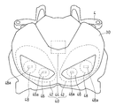
同自動二輪車の要部を示す正面図である。
同ヘッドランプ装置を示す斜視図である。
同ヘッドランプ装置を示す背面図である。
同ヘッドランプ装置の電源回路ユニット、ボックス、ランプブラケットの組立状態を示す斜視図である。
同電源回路ユニットを示す斜視図である。
同ボックスを示す斜視図である。
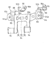
同ランプブラケットを示す斜視図である。
同ヘッドランプ装置の上部の車体への組立状態を示す、後方斜め上方から見た斜視図である。
同ヘッドランプ装置の下部の車体への組立状態を示す底面図である。
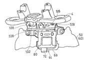
同ランプブラケットに設けたケーブル保持部材によるケーブル保持状態を示す、前方斜め左側方から見た斜視図である。
以下、本発明の好ましい実施形態について図面を参照しながら説明する。本明細書において、「左側」および「右側」は、車両に乗車した操縦者から見た左右側をいう。
図1は本発明が適用される自動二輪車を示す。この自動二輪車の車体フレームFRは、前半部を構成するメインフレーム1と、後半部を構成するリヤフレーム2とを有する。リヤフレーム2は、メインフレーム1の後部に連結されている。このメインフレーム1の前端にヘッドパイプ3が取り付けられ、このヘッドパイプ3にステアリングシャフト(図示せず)が回動自在に挿通されている。このステアリングシャフトに、トップブリッジ4およびボトムブリッジ5が取り付けられ、これらトップブリッジ4およびボトムブリッジ5にフロントフォーク8が支持されている。このフロントフォーク8の下端部に前輪9が支持され、前輪9の上方にフロントフェンダ15が取り付けられている。フロントフォーク8の上端部のトップブリッジ4に、ハンドル10が取り付けられている。
メインフレーム1の後端部には、スイングアームブラケット11が設けられている。このスイングアームブラケット11に、スイングアーム12が、前端部に挿通されたピボット軸13を介して上下揺動自在に支持されている。このスイングアーム12の後端部には後輪14が支持されている。メインフレーム1の中央下部にはエンジンEが支持されている。このエンジンEが、チェーンのような動力伝達機構16を介して後輪14を駆動する。
リヤフレーム2にライダーシート22と同乗者シート24とが支持され、リヤフレーム2の後端にテールランプ26が支持されている。テールランプ26の下方には、後輪14の上方に位置するリヤフェンダ36が取り付けられている。
メインフレーム1の上部、つまり、車体上部で、前記ハンドル10とライダーシート22との間には、燃料タンク25が取り付けられている。また、前記トップブリッジ4およびボトムブリッジ5にヘッドランプ装置40が支持されている。このヘッドランプ装置40に樹脂製のフロントカウル30が支持され、ヘッドランプ装置40を上方、下方および両側方から覆っている。フロントカウル30の後方に、樹脂製のサイドカウル31が装着され、燃料タンク25の下部からエンジンEの前方および下部にかけての部分を側方から覆っている。
図2に示すように、ヘッドランプ装置40は、ランプユニット42と電源回路ユニット44とを有している。ランプユニット42は、フロントカウル30の下方に配置されている。電源回路ユニット44は、ランプユニット42の左右方向中央部でランプユニット42の上方に配置されている。
ランプユニット42は、車幅方向内側に配置された左右一対のロービーム用ランプ46と、車幅方向外側に配置された左右一対のハイビーム用ランプ48とを有している。各ランプ46,48の光源46a,48aはLEDにより構成されている。電源回路ユニット44は、電源(図示しないバッテリ)からの直流電力を制御して光源46a,48aであるLEDに給電する。
図3はヘッドランプ装置40を前方斜め左側方から見た斜視図で、図4はヘッドランプ装置40の背面図である。図3に示すように、ヘッドランプ装置40のランプユニット42は、ランプ46,48(図2)を支持するフレーム(図示せず)が共通のランプベース50にボルト51および後述の調整ねじ62,64(図4)で連結されている。ランプベース50は、例えば、樹脂製である。ランプユニット42の前方にレンズカバー52が配置されている。レンズカバー52はランプベース50に爪で係合されたうえで、接着剤で固着される。
ランプベース50の上部および下部に、挿通孔54aを有するカウル取付片54がそれぞれ一体形成されている。カウル取付片54は、ランプベース50の上部に4つ、下部に2つ設けられている。図4では、上部のカウル取付片54は2つのみ見えている。これら挿通孔54aにボルト53を後方から挿入し、図2のフロントカウル30に設けたねじ孔(図示せず)に締め付ける。これにより、フロントカウル30がヘッドランプ装置40に装着される。
図3のランプベース50の上部における左右方向の中央部に、下方へ凹入した凹所56が設けられている。この凹所56に電源回路ユニット44が収納されている。詳細には、凹所56はランプベース50の上部の後部に設けられている。ランプベース50の上部に設けられる4つ前記カウル取付片54は、凹所56(図4)を挟んで左右側に2つずつ形成されている。左側に形成された2つのカウル取付片54の間に、後方に突出したスクリューボス55、55がそれぞれ形成されている。
図4に示すように、ランプベース50の背面における左右のランプ46,48に対応する位置に開口58,58が形成されている。この開口58,58からヒートシンク60,60が露出するように配置されている。ヒートシンク60は、LEDに取り付けられ、熱の放散によってLEDの温度を下げる役割を果たす。
ランプベース50の背面の上部の左右端部に、左右のランプユニット42,42の左右方向の光軸を調整するための左右方向調整ねじ62,62がそれぞれ設けられている。下部の左右方向中央に、左右のランプユニット42,42の上下方向の光軸を調整するための上下方向調整ねじ64,64が設けられている。
ランプベース50の背面の下部、詳細には、下部における上下方向調整ねじ64,64の外側に、下部ブラケット取付片66,66がそれぞれ形成されている。各下部ブラケット取付片66には、上下方向を向く下部ブラケット取付孔66aが形成されている。
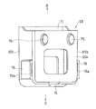
図6に示すように、電源回路ユニット44は、正面視で矩形のユニット本体68を有している。ユニット本体68の上部に上方を向いた出力側コネクタ70が2つ設けられ、下部に下方を向いた入力側コネクタ72が1つ設けられている。入力側コネクタ72は、電源回路ユニット44と車体側の電源とを接続するケーブルに接続されている。出力側コネクタ70は、電源回路ユニット44とランプユニット42とを接続するケーブルに接続される。
図4の電源回路ユニット44のユニット本体68は、上方に開口したボックス69に収納されている。ボックス69は、ゴムのような弾性体で形成されている。つまり、電源回路ユニット44とヘッドランプ装置40の凹所56との間に弾性体が介在している。
図7に示すように、ボックス69は、上部にボックス開口71を有するほぼ直方体形状であり、ボックス69の下部にコネクタ開口74が形成されている。図4に示すように、ユニット本体68がボックス69に収納された状態で、出力側コネクタ70がボックス開口71から上方に突出し、入力側コネクタ72がコネクタ開口74から下方に突出している。
図7のボックス69は、背面69aの上部に左右に並んで2つの係合突部76,76が形成されている。また、ボックス69の両側面69b、69bの下部に、外側方に突出するブラケット係止部78,78がそれぞれ形成されている。各ブラケット係止部78に、上下方向に長い係合溝78aが形成されている。
図4のヘッドランプ装置40は、上部ランプブラケット80および下部ランプブラケット82を介して、図1のトップブリッジ4およびボトムブリッジ5にそれぞれ取り付けられている。
上部ランプブラケット80は、図8に示すように、板金を折り曲げることで形成されている。上部ランプブラケット80は、左右方向中央部のボックス係止部84と、ボックス係止部84の左右両端部から左右方向にそれぞれ延びる上側ランプ支持部86,86と、各上側ランプ支持部86,86から後方に延びるブリッジ取付部88とを有している。図5に示すように、上側ランプ支持部86には、前後方向を向くランプ取付孔86aが形成されている。なお、図5では後述する第2の保持部材100が省略されている。
図8のボックス係止部84は、上部を構成する左右方向に長い長方形状の上半部90と、上半部90の両端部から下方に延びる一対の下半部92,92とを有する門型である。ボックス係止部84の上半部90に、前後方向を向いた貫通孔である係合孔90a,90aが左右に並んで2つ形成されている。ボックス係止部84の下半部92,92の下端に、前方に延びる係止片94,94がそれぞれ形成されている。
各ブリッジ取付部88,88の後端は、後方斜め上方に傾斜する傾斜壁96,96を有している。傾斜壁96,96に、ボルト挿通孔96a,96aが形成されている。各ブリッジ取付部88に、後述する第1の保持部材98と協働してケーブル類99(図11)を保持する第2の保持部材100が設けられている。第2の保持部材100は、ワイヤを折り曲げることで形成され、溶接によりブリッジ取付部88に固着されている。
図3に示すように、上部ランプブラケット80は、取付ブラケット102を介してトップブリッジ4に取り付けられる。取付ブラケット102は、左右の支持部材104,104と、これら支持部材104,104を接続する接続部材106とが、溶接により連結されて構成されている。支持部材104,104は、上部ランプブラケット80の左右のブリッジ取付部88,88の傾斜壁96,96にそれぞれ連結されている。支持部材104,104は、例えば金属性の板材で、接続部材106は、例えば金属性の棒材である。
支持部材104の後面には、溶接ナット108(図9)が固着されている。また、支持部材104における溶接ナット108(図9)より車幅方向内側にボルト挿通孔110が形成されている。なお、図3では、右側のボルト挿通孔110はボルトが挿通されていない状態を示し、左側のボルト挿通孔はボルト105が挿通されている状態を示している。支持部材104の前面に、前記ケーブル類99(図11)を挿通させて保持する前記第1の保持部材98が設けられている。第1の保持部材98は、ワイヤを折り曲げることで形成され、溶接により支持部材104に固着されている。
右側の支持部材104には、下方斜め外側方を向く第1のケーブル支持部112が設けられ、この第1のケーブル支持部112に第1の貫通孔112aが形成されている。第1のケーブル支持部112は、支持部材104の上端を前側に折り曲げて形成される。接続部材106に、上方斜め後方に延びる第2のケーブル支持部114が設けられている。第2のケーブル支持部114は、金属製の板材からなり、接続部材106に溶接により固着されている。第2のケーブル支持部114に、第2の貫通孔114aが形成されている。
上部ランプブラケット80と取付ブラケット102とにより、上下方向の開口が形成されている。この開口にケーブルを導くように、第1および第2の保持部材98,100と、第1および第2のケーブル支持部112,114とが配置されている。
図4に示すように、下部ランプブラケット82は、ヘッドランプ装置40の下部ブラケット取付片66,66にそれぞれ取り付けられる下側ランプ支持部116,116と、ボトムブリッジ5(図1)に取り付けられる車体取付部118とを有している。これら下側ランプ支持部116,116と車体取付部118とが、図10に明示された前後方向に延びる棒状の連結部材120,120により連結されている。図4の各部材の連結は溶接により行われている。車体取付部118は、左右方向に延びて上下方向を向く金属製の板材からなる。車体取付部118における左右方向両端部に、ねじ挿通孔122,122がそれぞれ形成されている。下部ランプブラケット82に、上部ランプブラケット80のようなケーブル保持部材を設けてもよい。
つぎに、電源回路ユニット44のランプベース50への組み付け、およびヘッドランプ装置40の車体への取り付けについて説明する。図5の電源回路ユニット44をボックス69の上部開口71に上方から嵌め込む。さらに、ボックス69の左右のブラケット係止部78,78の係合溝78a,78aに、図8の上部ランプブラケット80の左右の係止片94,94を係止させ、図7のボックス69の係合突部76,76を、図8の上部ランプブラケット80の係合孔90a,90aに係合させる。これによって、図5のボックス69が上部ランプブラケット80に係止される。これにより、電源回路ユニット44、ボックス69および上部ランプブラケット80が一体化される。
さらに、上部ランプブラケット80のランプ取付孔86aに、図8に示すように、両端に鍔が設けられた防振用の弾性グロメット124を嵌合する。つづいて、一体化された電源回路ユニット44、ボックス69および上部ランプブラケット80を、図4のランプベース50の上部の凹所56に収納する。このとき、ボックス69が凹所56の内面に圧接される。この状態で、弾性部材124の中心孔124a(図8)に、スクリュー126を後方から挿通し、図3に示すランプベース50のスクリューボス55に締め付ける。これにより、ランプユニット42と電源回路ユニット44とが上部ランプブラケット80に支持される。
つぎに、トップブリッジ4に取付ブラケット102を取り付ける。具体的には、取付ブラケット102のボルト挿通孔110に、ボルト105を前方から挿通し、トップブリッジ4に形成したねじ孔(図示せず)に締め付ける。
さらに、ボトムブリッジ5に、図4の下部ランプブラケット82を取り付ける。具体的には、下部ランプブラケット82のねじ挿通孔122に、下方から図10のねじ体134を挿通し、ボトムブリッジ5に設けたねじ孔(図示せず)にねじ込む。
つづいて、フロントカウル30をヘッドランプ装置40に取り付ける。図3のランプベース50のカウル取付片54に設けた挿通孔54aに、図4のボルト53を後方から挿入し、図2のフロントカウル30に設けたねじ孔(図示せず)に締め付ける。これにより、フロントカウル30がヘッドランプ装置40に装着される。
つぎに、フロントカウル30が固定されたヘッドランプ装置40を車体に取り付ける。まず、ヘッドランプ装置40の上部のトップブリッジ4への取り付けについて説明する。具体的には、図4の上部ランプブラケット80のボルト挿通孔96aに、図3のボルト128を前方から挿通し、取付ブラケット102の支持部材104を貫通して溶接ナット108(図9)にねじ込む。これによって、上部ランプブラケット80が取付ブラケット102に取り付けられる。これにより、ヘッドランプ装置40の上部が、上部ランプブラケット80および取付ブラケット102を介してトップブリッジ4に支持される。
つづいて、ヘッドランプ装置40の下部のボトムブリッジ5への取り付けについて説明する。具体的には、図4のランプベース50の下部ブラケット取付片66の下部ブラケット取付孔66aに、両端に鍔が設けられた防振用の弾性グロメット130を装着する。下部ランプブラケット82の下側ランプ支持部116に固定されたピン132を、下方からグロメット130の中心孔に嵌合する。ピン132は、下側ランプ支持部116に溶接により固着されている。これにより、図10のヘッドランプ装置40の下部が、下部ランプブラケット82を介してボトムブリッジ5に支持される。
つぎに、ケーブル保持構造について説明する。図11に示すように、トップブリッジ4に支持されるハンドル10、メータユニット6等からのケーブル類99は、取付ブラケット102に設けた第1の保持部材98および上部ランプブラケット80に設けた第2の保持部材100に案内されて、取付ブラケット102と上部ランプブラケット80とで形成される上下方向の開口に導かれる。ケーブル類99は、例えば、アクセルグリップ用ケーブル、グリップスイッチ用ケーブル、ブレーキホース、メータ用ハーネス、クラッチホース等である。
ケーブル類99の一部、例えば、ブレーキホース99aは、取付ブラケット102の第1のケーブル支持部112に支持される。具体的には、ブレーキホース99aを弾性グロメット136に挿通し、第1のケーブル支持部112の第1の貫通孔112aに取り付けたクランプ部材138で、この弾性部材136を挟持する。これにより、ブレーキホース99aが取付ブラケット102に支持される。
また、ケーブル類99の一部、例えばメータ用ハーネス99bが、取付ブラケット102の第2のケーブル支持部114に支持される。具体的には、第2のケーブル支持部114の第2の貫通孔114a(図3)に取り付けた結束部材140で、メータ用ハーネス99bを保持する。これにより、メータ用ハーネス99bが取付ブラケット102に支持される。
このようにして、ヘッドランプ装置40、フロントカウル30、上部および下部ランプブラケット80,82、取付ブラケット102、ケーブル類99からなるアッシーが構成される。このアッシーを、図1のトップブリッジ4およびボトムブリッジ5に取り付けることで、ヘッドランプ装置40およびフロントカウル30が車体に支持される。ケーブル類99はコネクタを介して各機器に接続される。
上記構成において、図2に示すランプユニット42の光源46a,48aとして、LEDが使用されているので、ランプユニット42を小形化できる。このように小形化されたランプユニット42をフロントカウル30内部の最も下方の位置に配置することで、フロントカウル30を小形化してもフロントカウル30内に容易に収納できる。フロントカウル30は、上部の前後方向長さが小さく下部の前後方向長さが長い先すぼまり形状であるから、スペースに余裕があるフロントカウル30内部の下方にランプユニットを配置するのが小形のフロントカウル30には好ましい。
このとき、図4のランプユニット42の上部に設けた凹所56に電源回路ユニット44を収納しているので、電源回路ユニット44に邪魔されずにランプユニット42をフロントカウル30内の下部に配置できる。こうして、フロントカウル30を小形化しつつ、ランプユニット42と電源回路ユニット44とをフロントカウル30内にコンパクトに収納できる。
また、電源回路ユニット44とランプユニット42の凹所56との間に、弾性体からなるボックス69が介在しているので、弾性体により電源回路ユニット44とランプユニット42との前後方向および左右方向の位置ずれが吸収される。
さらに、ボックス69を凹所56に収納するだけで電源回路ユニット44がランプユニット42に組み込まれるので、組立が容易である。また、ボックス69が凹所56の内面に圧接されているので、ボックス69のランプユニット42に対する相対位置が安定する。これにより、ボックス69と上部ランプブラケット80とは、締結ではなく、簡単な差込み式の係止構造により連結できる。さらに、ボックス69は弾性体からなるので、走行時に上部ランプブラケット80から伝達される振動も吸収される。
さらに、上部ランプブラケット80が、ランプユニット42および電源回路ユニット44の両方の支持を兼用するので、部品点数、組立工数が低減する。また、ヘッドランプ装置40およびフロントカウル30に、上部ランプブラケット80および取付ブラケット102を連結して介してアッシーが構成され、このアッシーをトップブリッジ4に取り付けることで、ヘッドランプ装置30およびフロントカウル40が車体に組み付けられる。したがって、ヘッドランプ装置40およびフロントカウル30の組立性が向上する。
図11に示す取付ブラケット102および上部ランプブラケット80に、第1および第2の保持部材98,100がそれぞれ設けられているので、取付ブラケット102および上部ランプブラケット80をケーブル保持用にも兼用できる。さらに、上記アッシーを構成した際に、ケーブル類99を第1および第2の保持部材98,100で保持することで組立性が一層向上する。
本発明は、以上の実施形態に限定されるものでなく、本発明の要旨を逸脱しない範囲内で、種々の追加、変更または削除が可能である。したがって、そのようなものも本発明の範囲内に含まれる。
4 トップブリッジ
8 フロントフォーク
30 フロントカウル
40 ヘッドランプ装置
42 ランプユニット
44 電源回路ユニット
46a,48a 光源(LED)
56 凹所
69 ボックス(弾性体)
80 上部ランプブラケット(ランプブラケット)
98 第1の保持部材
100 第2の保持部材
102 取付ブラケット
8 フロントフォーク
30 フロントカウル
40 ヘッドランプ装置
42 ランプユニット
44 電源回路ユニット
46a,48a 光源(LED)
56 凹所
69 ボックス(弾性体)
80 上部ランプブラケット(ランプブラケット)
98 第1の保持部材
100 第2の保持部材
102 取付ブラケット
Claims (7)
- 自動二輪車のフロントカウル内に収納されるヘッドランプ装置であって、
LEDを光源とするランプユニットと、電源からの電力を制御して前記光源に給電する電源回路ユニットとを備え、
前記電源回路ユニットが、前記ランプユニットの上部に設けた凹所に収納されている自動二輪車のヘッドランプ装置。 - 請求項1に記載の自動二輪車のヘッドランプ装置において、前記電源回路ユニットと前記ランプユニットの前記凹所との間に弾性体が介在している自動二輪車のヘッドランプ装置。
- 請求項2に記載の自動二輪車のヘッドランプ装置において、前記凹所が前記ランプユニットの上部の後部に設けられ、
前記電源回路ユニットが、上方に開口した前記弾性体からなるボックスに収納されて前記凹所の内面に圧接されている自動二輪車のヘッドランプ装置。 - 請求項1,2または3に記載の自動二輪車のヘッドランプ装置おいて、前記電源回路ユニットと前記ランプユニットがランプブラケットに支持され、
前記ランプブラケットが、フロントフォークを支持するトップブリッジに取り付けられている自動二輪車のヘッドランプ装置。 - 請求項4に記載の自動二輪車のヘッドランプ装置において、前記ランプブラケットが、取付ブラケットを介して前記トップブリッジに取り付けられている自動二輪車のヘッドランプ装置。
- 請求項5に記載の自動二輪車のヘッドランプ装置において、前記取付ブラケットに、ケーブル類を挿通させて保持する第1の保持部材が設けられている自動二輪車のヘッドランプ装置。
- 請求項6に記載の自動二輪車のヘッドランプ装置において、前記ランプブラケットに、前記第1の保持部材と協働して前記ケーブル類を保持する第2の保持部材が設けられている自動二輪車のヘッドランプ装置。
Priority Applications (3)
| Application Number | Priority Date | Filing Date | Title |
|---|---|---|---|
| CN201380065993.4A CN104870300B (zh) | 2012-12-14 | 2013-10-24 | 自动二轮车的前灯装置 |
| EP13863502.4A EP2933173B1 (en) | 2012-12-14 | 2013-10-24 | Motorcycle |
| US14/731,265 US9963064B2 (en) | 2012-12-14 | 2015-06-04 | Headlight device for motorcycle |
Applications Claiming Priority (2)
| Application Number | Priority Date | Filing Date | Title |
|---|---|---|---|
| JP2012273252A JP6026879B2 (ja) | 2012-12-14 | 2012-12-14 | 自動二輪車のヘッドランプ装置 |
| JP2012-273252 | 2012-12-14 |
Related Child Applications (1)
| Application Number | Title | Priority Date | Filing Date |
|---|---|---|---|
| US14/731,265 Continuation US9963064B2 (en) | 2012-12-14 | 2015-06-04 | Headlight device for motorcycle |
Publications (1)
| Publication Number | Publication Date |
|---|---|
| WO2014091826A1 true WO2014091826A1 (ja) | 2014-06-19 |
Family
ID=50934124
Family Applications (1)
| Application Number | Title | Priority Date | Filing Date |
|---|---|---|---|
| PCT/JP2013/078838 Ceased WO2014091826A1 (ja) | 2012-12-14 | 2013-10-24 | 自動二輪車のヘッドランプ装置 |
Country Status (5)
| Country | Link |
|---|---|
| US (1) | US9963064B2 (ja) |
| EP (1) | EP2933173B1 (ja) |
| JP (1) | JP6026879B2 (ja) |
| CN (1) | CN104870300B (ja) |
| WO (1) | WO2014091826A1 (ja) |
Cited By (1)
| Publication number | Priority date | Publication date | Assignee | Title |
|---|---|---|---|---|
| CN109383682A (zh) * | 2018-11-28 | 2019-02-26 | 南京金城机械有限公司 | 摩托车头部安装连接结构 |
Families Citing this family (15)
| Publication number | Priority date | Publication date | Assignee | Title |
|---|---|---|---|---|
| JP6130222B2 (ja) * | 2013-05-24 | 2017-05-17 | 川崎重工業株式会社 | 自動二輪車のハーネス支持構造 |
| JP6306533B2 (ja) * | 2015-03-30 | 2018-04-04 | 本田技研工業株式会社 | 鞍乗り型車両の前部構造 |
| JP6192238B2 (ja) * | 2015-09-30 | 2017-09-06 | 本田技研工業株式会社 | 自動二輪車 |
| JP6844955B2 (ja) * | 2016-05-10 | 2021-03-17 | 川崎重工業株式会社 | 乗物用のヘッドランプ装置 |
| JP6739991B2 (ja) * | 2016-05-10 | 2020-08-12 | 川崎重工業株式会社 | 鞍乗型乗物のヘッドランプ装置 |
| JP6702794B2 (ja) | 2016-05-10 | 2020-06-03 | 川崎重工業株式会社 | 鞍乗型乗物用のヘッドランプ装置 |
| JP2018094942A (ja) * | 2016-12-08 | 2018-06-21 | ヤマハ発動機株式会社 | 鞍乗型車両 |
| JP6545201B2 (ja) * | 2017-01-13 | 2019-07-17 | 本田技研工業株式会社 | 鞍乗り型車両の車体前部構造 |
| EP3746332B1 (en) * | 2018-02-02 | 2023-12-27 | Varroc Engineering Private Limited | Headlight assembly for two-wheeler |
| JP6982173B2 (ja) * | 2018-05-23 | 2021-12-17 | 本田技研工業株式会社 | 鞍乗型車両 |
| JP7273605B2 (ja) * | 2019-04-24 | 2023-05-15 | カワサキモータース株式会社 | 鞍乗車両 |
| JP7046892B2 (ja) * | 2019-11-26 | 2022-04-04 | 本田技研工業株式会社 | 鞍乗り型車両 |
| JP7585626B2 (ja) * | 2020-06-12 | 2024-11-19 | スズキ株式会社 | 鞍乗型車両のフロント構造 |
| JP2022040831A (ja) * | 2020-08-31 | 2022-03-11 | ヤマハ発動機株式会社 | 鞍乗型車両 |
| JP7563094B2 (ja) * | 2020-10-09 | 2024-10-08 | スズキ株式会社 | レクチファイヤの支持構造 |
Citations (7)
| Publication number | Priority date | Publication date | Assignee | Title |
|---|---|---|---|---|
| JPH09293403A (ja) * | 1996-04-30 | 1997-11-11 | Koito Mfg Co Ltd | 放電バルブを有する車両用灯具 |
| JPH11238405A (ja) * | 1998-02-23 | 1999-08-31 | Suzuki Motor Corp | 車両用前照灯装置 |
| JP4376528B2 (ja) | 2003-03-06 | 2009-12-02 | 本田技研工業株式会社 | 自動二輪車の前部灯火装置 |
| JP2010116127A (ja) * | 2008-11-14 | 2010-05-27 | Honda Motor Co Ltd | 自動二輪車の盗難対策装置 |
| JP2011173504A (ja) * | 2010-02-24 | 2011-09-08 | Suzuki Motor Corp | 車両のヘッドライト装置 |
| JP2011235881A (ja) * | 2010-05-07 | 2011-11-24 | Honda Motor Co Ltd | 自動二輪車のヘッドライト装置 |
| WO2012120947A1 (ja) * | 2011-03-04 | 2012-09-13 | 本田技研工業株式会社 | 車両の灯火装置及び同装置の取付構造 |
Family Cites Families (14)
| Publication number | Priority date | Publication date | Assignee | Title |
|---|---|---|---|---|
| JP3132987B2 (ja) | 1995-07-19 | 2001-02-05 | 三菱重工業株式会社 | 金属片の連続鋳造方法及び金属片の連続鋳造用電磁ブレーキ装置 |
| JP4377460B2 (ja) * | 1998-01-09 | 2009-12-02 | 本田技研工業株式会社 | 自動二輪車の放電ランプ用点灯回路取付け構造 |
| JP4333887B2 (ja) * | 1999-03-31 | 2009-09-16 | 本田技研工業株式会社 | 車両用前照灯装置 |
| JP2003205878A (ja) * | 2002-01-16 | 2003-07-22 | Suzuki Motor Corp | 自動二輪車の前照灯取付け構造 |
| US7287889B2 (en) | 2003-03-06 | 2007-10-30 | Honda Motor Co., Ltd. | Lamp apparatus for vehicle |
| JP2007030835A (ja) * | 2005-07-29 | 2007-02-08 | Yamaha Motor Co Ltd | 自動二輪車 |
| JP2009161011A (ja) * | 2007-12-28 | 2009-07-23 | Yamaha Motor Co Ltd | 自動二輪車 |
| JP5239052B2 (ja) * | 2008-02-26 | 2013-07-17 | 本田技研工業株式会社 | 小型車両用ヘッドライト |
| TW201033063A (en) * | 2009-03-10 | 2010-09-16 | Kwang Yang Motor Co | Structure of motorcycle front lamp |
| US8413754B2 (en) * | 2009-12-29 | 2013-04-09 | Kawasaki Jukogyo Kabushiki Kaisha | Straddle vehicle |
| JP5393889B2 (ja) * | 2010-07-05 | 2014-01-22 | 三菱電機株式会社 | ヘッドランプ用led光源点灯装置 |
| CN202368720U (zh) * | 2011-12-13 | 2012-08-08 | 力帆实业(集团)股份有限公司 | 多功能摩托车大灯支架 |
| DE202012004965U1 (de) * | 2012-05-19 | 2012-06-15 | Automotive Lighting Reutlingen Gmbh | Gasdichte LED-Leuchte |
| JP6101452B2 (ja) * | 2012-08-31 | 2017-03-22 | 本田技研工業株式会社 | 鞍乗型車両のヘッドライト支持構造 |
-
2012
- 2012-12-14 JP JP2012273252A patent/JP6026879B2/ja active Active
-
2013
- 2013-10-24 CN CN201380065993.4A patent/CN104870300B/zh active Active
- 2013-10-24 WO PCT/JP2013/078838 patent/WO2014091826A1/ja not_active Ceased
- 2013-10-24 EP EP13863502.4A patent/EP2933173B1/en active Active
-
2015
- 2015-06-04 US US14/731,265 patent/US9963064B2/en active Active
Patent Citations (7)
| Publication number | Priority date | Publication date | Assignee | Title |
|---|---|---|---|---|
| JPH09293403A (ja) * | 1996-04-30 | 1997-11-11 | Koito Mfg Co Ltd | 放電バルブを有する車両用灯具 |
| JPH11238405A (ja) * | 1998-02-23 | 1999-08-31 | Suzuki Motor Corp | 車両用前照灯装置 |
| JP4376528B2 (ja) | 2003-03-06 | 2009-12-02 | 本田技研工業株式会社 | 自動二輪車の前部灯火装置 |
| JP2010116127A (ja) * | 2008-11-14 | 2010-05-27 | Honda Motor Co Ltd | 自動二輪車の盗難対策装置 |
| JP2011173504A (ja) * | 2010-02-24 | 2011-09-08 | Suzuki Motor Corp | 車両のヘッドライト装置 |
| JP2011235881A (ja) * | 2010-05-07 | 2011-11-24 | Honda Motor Co Ltd | 自動二輪車のヘッドライト装置 |
| WO2012120947A1 (ja) * | 2011-03-04 | 2012-09-13 | 本田技研工業株式会社 | 車両の灯火装置及び同装置の取付構造 |
Cited By (2)
| Publication number | Priority date | Publication date | Assignee | Title |
|---|---|---|---|---|
| CN109383682A (zh) * | 2018-11-28 | 2019-02-26 | 南京金城机械有限公司 | 摩托车头部安装连接结构 |
| CN109383682B (zh) * | 2018-11-28 | 2024-01-19 | 南京金城机械有限公司 | 摩托车头部安装连接结构 |
Also Published As
| Publication number | Publication date |
|---|---|
| JP6026879B2 (ja) | 2016-11-16 |
| CN104870300B (zh) | 2018-01-12 |
| US20150266410A1 (en) | 2015-09-24 |
| EP2933173A1 (en) | 2015-10-21 |
| JP2014117994A (ja) | 2014-06-30 |
| EP2933173A4 (en) | 2016-09-14 |
| CN104870300A (zh) | 2015-08-26 |
| US9963064B2 (en) | 2018-05-08 |
| EP2933173B1 (en) | 2017-12-06 |
Similar Documents
| Publication | Publication Date | Title |
|---|---|---|
| JP6026879B2 (ja) | 自動二輪車のヘッドランプ装置 | |
| CN105228890B (zh) | 自动二轮车的电线束支承构造 | |
| US10391925B2 (en) | Vehicle headlight with a plurality of inner non spherical lenses transmitting light from a high beam and a low beam light source | |
| US20110273896A1 (en) | Headlamp device for two-wheeled motor vehicle | |
| JP2020119768A (ja) | 車両用灯具 | |
| CN104870301B (zh) | 机动两轮车的位置灯安装结构 | |
| EP2933174A1 (en) | Saddled vehicle | |
| JP2005082051A (ja) | ウインカ装置 | |
| US11414148B2 (en) | Straddled vehicle | |
| CN102275617B (zh) | 跨骑型车辆用车灯器支承装置 | |
| CN100522728C (zh) | 前照灯支承构造体 | |
| CN107406111B (zh) | 用于摩托车的头灯安装结构 | |
| JP2009132219A (ja) | 自動二輪車 | |
| JP2024127041A (ja) | 乗物のカメラの取付構造 | |
| JP4758286B2 (ja) | ヘッドランプ装置 | |
| JP4915528B2 (ja) | 自動二輪車用の灯火器 | |
| WO2020085491A1 (ja) | 鞍乗車両のヘッドランプ装置 | |
| EP3960599B1 (en) | Straddled vehicle | |
| JP2016037213A (ja) | フレームカバー構造 | |
| KR200268275Y1 (ko) | 이륜자동차의 와이어링 지지구조 | |
| JP4447268B2 (ja) | ヘッドランプカバー | |
| WO2023189927A1 (ja) | 車両用灯具 | |
| JP2022094436A (ja) | ハンドルバー用操作装置 | |
| JP2023019172A (ja) | 鞍乗型車両のメータブラケット |
Legal Events
| Date | Code | Title | Description |
|---|---|---|---|
| 121 | Ep: the epo has been informed by wipo that ep was designated in this application |
Ref document number: 13863502 Country of ref document: EP Kind code of ref document: A1 |
|
| NENP | Non-entry into the national phase |
Ref country code: DE |
|
| WWE | Wipo information: entry into national phase |
Ref document number: 2013863502 Country of ref document: EP |