WO2014091844A1 - 車両用情報提供装置 - Google Patents
車両用情報提供装置 Download PDFInfo
- Publication number
- WO2014091844A1 WO2014091844A1 PCT/JP2013/080177 JP2013080177W WO2014091844A1 WO 2014091844 A1 WO2014091844 A1 WO 2014091844A1 JP 2013080177 W JP2013080177 W JP 2013080177W WO 2014091844 A1 WO2014091844 A1 WO 2014091844A1
- Authority
- WO
- WIPO (PCT)
- Prior art keywords
- unit
- vehicle
- display
- information
- external
- Prior art date
- Legal status (The legal status is an assumption and is not a legal conclusion. Google has not performed a legal analysis and makes no representation as to the accuracy of the status listed.)
- Ceased
Links
Images




Classifications
-
- B—PERFORMING OPERATIONS; TRANSPORTING
- B60—VEHICLES IN GENERAL
- B60K—ARRANGEMENT OR MOUNTING OF PROPULSION UNITS OR OF TRANSMISSIONS IN VEHICLES; ARRANGEMENT OR MOUNTING OF PLURAL DIVERSE PRIME-MOVERS IN VEHICLES; AUXILIARY DRIVES FOR VEHICLES; INSTRUMENTATION OR DASHBOARDS FOR VEHICLES; ARRANGEMENTS IN CONNECTION WITH COOLING, AIR INTAKE, GAS EXHAUST OR FUEL SUPPLY OF PROPULSION UNITS IN VEHICLES
- B60K35/00—Instruments specially adapted for vehicles; Arrangement of instruments in or on vehicles
- B60K35/10—Input arrangements, i.e. from user to vehicle, associated with vehicle functions or specially adapted therefor
-
- B—PERFORMING OPERATIONS; TRANSPORTING
- B60—VEHICLES IN GENERAL
- B60K—ARRANGEMENT OR MOUNTING OF PROPULSION UNITS OR OF TRANSMISSIONS IN VEHICLES; ARRANGEMENT OR MOUNTING OF PLURAL DIVERSE PRIME-MOVERS IN VEHICLES; AUXILIARY DRIVES FOR VEHICLES; INSTRUMENTATION OR DASHBOARDS FOR VEHICLES; ARRANGEMENTS IN CONNECTION WITH COOLING, AIR INTAKE, GAS EXHAUST OR FUEL SUPPLY OF PROPULSION UNITS IN VEHICLES
- B60K35/00—Instruments specially adapted for vehicles; Arrangement of instruments in or on vehicles
- B60K35/20—Output arrangements, i.e. from vehicle to user, associated with vehicle functions or specially adapted therefor
- B60K35/21—Output arrangements, i.e. from vehicle to user, associated with vehicle functions or specially adapted therefor using visual output, e.g. blinking lights or matrix displays
- B60K35/22—Display screens
-
- B—PERFORMING OPERATIONS; TRANSPORTING
- B60—VEHICLES IN GENERAL
- B60K—ARRANGEMENT OR MOUNTING OF PROPULSION UNITS OR OF TRANSMISSIONS IN VEHICLES; ARRANGEMENT OR MOUNTING OF PLURAL DIVERSE PRIME-MOVERS IN VEHICLES; AUXILIARY DRIVES FOR VEHICLES; INSTRUMENTATION OR DASHBOARDS FOR VEHICLES; ARRANGEMENTS IN CONNECTION WITH COOLING, AIR INTAKE, GAS EXHAUST OR FUEL SUPPLY OF PROPULSION UNITS IN VEHICLES
- B60K35/00—Instruments specially adapted for vehicles; Arrangement of instruments in or on vehicles
- B60K35/20—Output arrangements, i.e. from vehicle to user, associated with vehicle functions or specially adapted therefor
- B60K35/29—Instruments characterised by the way in which information is handled, e.g. showing information on plural displays or prioritising information according to driving conditions
-
- B—PERFORMING OPERATIONS; TRANSPORTING
- B60—VEHICLES IN GENERAL
- B60K—ARRANGEMENT OR MOUNTING OF PROPULSION UNITS OR OF TRANSMISSIONS IN VEHICLES; ARRANGEMENT OR MOUNTING OF PLURAL DIVERSE PRIME-MOVERS IN VEHICLES; AUXILIARY DRIVES FOR VEHICLES; INSTRUMENTATION OR DASHBOARDS FOR VEHICLES; ARRANGEMENTS IN CONNECTION WITH COOLING, AIR INTAKE, GAS EXHAUST OR FUEL SUPPLY OF PROPULSION UNITS IN VEHICLES
- B60K35/00—Instruments specially adapted for vehicles; Arrangement of instruments in or on vehicles
- B60K35/80—Arrangements for controlling instruments
-
- B—PERFORMING OPERATIONS; TRANSPORTING
- B60—VEHICLES IN GENERAL
- B60K—ARRANGEMENT OR MOUNTING OF PROPULSION UNITS OR OF TRANSMISSIONS IN VEHICLES; ARRANGEMENT OR MOUNTING OF PLURAL DIVERSE PRIME-MOVERS IN VEHICLES; AUXILIARY DRIVES FOR VEHICLES; INSTRUMENTATION OR DASHBOARDS FOR VEHICLES; ARRANGEMENTS IN CONNECTION WITH COOLING, AIR INTAKE, GAS EXHAUST OR FUEL SUPPLY OF PROPULSION UNITS IN VEHICLES
- B60K35/00—Instruments specially adapted for vehicles; Arrangement of instruments in or on vehicles
- B60K35/80—Arrangements for controlling instruments
- B60K35/81—Arrangements for controlling instruments for controlling displays
-
- B—PERFORMING OPERATIONS; TRANSPORTING
- B60—VEHICLES IN GENERAL
- B60K—ARRANGEMENT OR MOUNTING OF PROPULSION UNITS OR OF TRANSMISSIONS IN VEHICLES; ARRANGEMENT OR MOUNTING OF PLURAL DIVERSE PRIME-MOVERS IN VEHICLES; AUXILIARY DRIVES FOR VEHICLES; INSTRUMENTATION OR DASHBOARDS FOR VEHICLES; ARRANGEMENTS IN CONNECTION WITH COOLING, AIR INTAKE, GAS EXHAUST OR FUEL SUPPLY OF PROPULSION UNITS IN VEHICLES
- B60K2360/00—Indexing scheme associated with groups B60K35/00 or B60K37/00 relating to details of instruments or dashboards
- B60K2360/18—Information management
- B60K2360/184—Displaying the same information on different displays
-
- B—PERFORMING OPERATIONS; TRANSPORTING
- B60—VEHICLES IN GENERAL
- B60K—ARRANGEMENT OR MOUNTING OF PROPULSION UNITS OR OF TRANSMISSIONS IN VEHICLES; ARRANGEMENT OR MOUNTING OF PLURAL DIVERSE PRIME-MOVERS IN VEHICLES; AUXILIARY DRIVES FOR VEHICLES; INSTRUMENTATION OR DASHBOARDS FOR VEHICLES; ARRANGEMENTS IN CONNECTION WITH COOLING, AIR INTAKE, GAS EXHAUST OR FUEL SUPPLY OF PROPULSION UNITS IN VEHICLES
- B60K2360/00—Indexing scheme associated with groups B60K35/00 or B60K37/00 relating to details of instruments or dashboards
- B60K2360/55—Remote control arrangements
- B60K2360/56—Remote control arrangements using mobile devices
- B60K2360/566—Mobile devices displaying vehicle information
Definitions
- the present invention relates to a vehicle information providing apparatus that provides various types of information to a vehicle user, and more particularly, to a vehicle information providing apparatus that provides various types of information using a vehicle-mounted device and an external device.
- Patent Document 1 a vehicle-mounted device (vehicle-mounted device) such as a vehicle-mounted navigation device and a mobile terminal (external device) are connected by wire or wirelessly, and a connection state between the vehicle-mounted device and the mobile terminal Is detected, the control device on the mobile terminal side supplies the display data (external information of the vehicle) displayed on the screen of the mobile terminal to the in-vehicle device side, and the control device on the in-vehicle device side supplies from the mobile terminal The displayed display data is displayed on the in-vehicle device side display.
- vehicle-mounted device vehicle-mounted device
- a mobile terminal external device
- the control device on the mobile terminal side supplies the display data (external information of the vehicle) displayed on the screen of the mobile terminal to the in-vehicle device side
- the control device on the in-vehicle device side supplies from the mobile terminal
- the displayed display data is displayed on the in-vehicle device side display.
- the user of the vehicle can visually recognize the information to be displayed on the screen of the external device such as the portable terminal on the on-vehicle device side display (display unit) having a larger screen.
- the display information of the portable terminal is displayed on the large-screen in-vehicle device side display installed at the optimal position in the vehicle. Can be confirmed.
- the life cycle (function evolution) of the product is very short compared to the in-vehicle device, and the interface part on the mobile terminal side changes within the life cycle of the in-vehicle device (for example, (Change from wired communication to wireless communication). Since the user of the vehicle displays the display data displayed on the screen of the latest mobile terminal on the in-vehicle device display side having a larger screen size, it is necessary to replace the in-vehicle device.
- the present invention provides external information held by an external device to a vehicle user via a display unit provided in the vehicle-mounted device, while avoiding an increase in cost. It is an object of the present invention to provide a vehicle information providing apparatus that can cope with a change in specifications of an interface unit of a device.
- the present invention provides a device unit having a display unit that displays various vehicle states as vehicle state information to a user and first control means for operating the display unit, and outputs external information of the vehicle to the device unit.
- a vehicle-mounted device having a communication unit that performs communication between the external device and the device unit, wherein the communication unit is configured to be connectable via the device unit and attachment / detachment means, and the device unit is When connected to the communication unit via attachment / detachment means, a signal including at least one of a video signal and a sound signal is output to the device unit as external information of the vehicle.
- the display unit displays a first display area for displaying predetermined information among the vehicle state information, and a second display area for displaying other information of the vehicle state information different from the predetermined information.
- the first control unit is connected to the communication unit via the attachment / detachment unit, the first display mode for displaying the vehicle state information on the display unit and the vehicle state information And a second display mode for displaying the external information of the vehicle on the display unit, and the external information of the vehicle is displayed in the second display area in the second display mode.
- the display unit is operated.
- the operation information when the first control means detects operation information related to operation of the external device output from the operation means by the user operating a predetermined operation means, the operation information Is output to a second control unit provided in the external device via the communication unit, and the second control unit operates the external device based on the operation information.
- the external device is composed of at least two external devices having different communication interfaces
- the communication unit is connected to one external device of the at least two external devices.
- the communication unit comprising: a type of interface unit; at least two types of decoders provided so as to correspond to the at least two types of interface units; and a selection unit for selecting outputs from the at least two types of decoders.
- the control unit is configured to control the selection unit according to the one external device connected thereto.
- the sound signal output from the communication unit is input to a sounding body via a sounding body driving circuit having an amplifier, and the sounding body driving circuit is separate from the communication unit or the device unit. It is comprised by the member, It is characterized by the above-mentioned.
- control unit provided in the communication unit receives the vehicle state information via the device unit and the attaching / detaching means, and the received vehicle state information is provided in the external device. 2 to the control means.
- the first control unit displays the operation information related to the operation of the external device in the second display area when the second display mode is executed. It is characterized by operating.
- the present invention is characterized in that the operation means is configured to be able to operate at least one of the operation of the device unit and the operation of the external device.
- the present invention can respond to changes in the specifications of the interface unit of the external device while avoiding an increase in cost when providing external information possessed by the external device to the vehicle user via the display unit provided in the vehicle mounted device.
- a vehicle information providing device can be provided.
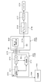
- the block diagram which shows the connection state of the information provision apparatus for vehicles by 1st Embodiment of this invention, and various electrical components.
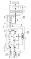
- the block diagram of the information provision apparatus for vehicles by the embodiment It is a block diagram of the information provision apparatus for vehicles when the vehicle equipment according to the embodiment and an external device are wirelessly connected. It is a block diagram of the information provision apparatus for vehicles in case the vehicle-mounted apparatus and external apparatus by the same embodiment are wired-connected. It is a general-view figure which shows an example of the vehicle mounting apparatus by the same embodiment. It is a figure which shows the display layout of the 1st display part in the 1st display mode by the embodiment.
- (A) is a figure which shows the display layout of the 1st display part in the 2nd display mode by the embodiment
- (b) is a 2nd display mode by the same embodiment
- the 1st control means is a warning. It is a figure which shows the display layout of the 1st display part at the time of receiving a signal.
- (A) is a figure which shows the display layout of the 1st display part in 2nd display mode by 2nd Embodiment of this invention
- (b) is 2nd in the 2nd display mode by the 2nd embodiment.
- FIG. 1 is a block diagram showing an embodiment of the present invention.
- 100 indicates a vehicle.
- Reference numeral 101 denotes a vehicular information providing apparatus.
- the vehicular information providing apparatus 101 includes a vehicle-mounted device (here, a vehicle instrument) 102 and an external device (here, a smartphone) that is a portable information terminal.
- the vehicle-mounted device 102 is connected to electrical components such as an audio 106, an air conditioner 107, a body control unit 108, and an engine control unit 109 via an in-vehicle LAN (multiplex communication line) 105. Further, the external device 103 connected to the vehicle-mounted device 102 via the connection means 104 can be connected to the Internet via the external communication means 110.
- electrical components such as an audio 106, an air conditioner 107, a body control unit 108, and an engine control unit 109 via an in-vehicle LAN (multiplex communication line) 105.
- the external device 103 connected to the vehicle-mounted device 102 via the connection means 104 can be connected to the Internet via the external communication means 110.
- the vehicle-mounted device 102 includes a device unit 200 and a first communication unit 220 as a communication unit, and the first communication unit 220 performs communication between the device unit 200 and the external device 103. is there.
- the device unit 200 includes a vehicle information terminal (vehicle information means) 210 and a multiplex communication input / output terminal (multiplex communication input / output means) 211 for inputting / outputting various information (vehicle state signals) relating to various states of the vehicle, and a predetermined operation.
- vehicle information terminal vehicle information means
- multiplex communication input / output terminal multiplex communication input / output means
- the control means 202 the first storage means 203 comprising a non-volatile memory such as a flash memory or EEPROM in which the processing program of the first control means 202 is stored, and various information (various states of the vehicle) to the vehicle user
- the first display unit (display unit) 204 such as a liquid crystal display panel or an organic EL panel for visually informing the vehicle and various information to the vehicle user
- the first notifying means 206 including the first sounding body 205 such as a speaker for audibly informing various states of the vehicle, and also the drive control of the first display unit 204 and the first sounding body 205.
- first driving means 207 the first driving means 207.
- the first sounding body 205 may be a helmet speaker housed in a helmet worn by a passenger (user) who rides on the motorcycle.
- the operation means 213 includes an operation input unit for performing various operations of the vehicle-mounted device 102, and includes, for example, a cursor button and a determination button that are installed at appropriate locations in the vehicle so that the user can reach them.
- a cross key type operation input unit can be applied, and an operation instruction signal (remote operation instruction signal) to the external device 103 output from the operation unit 213 when the user operates the operation unit 213 is an operation information terminal 212.
- it is input to the first control unit 202 through the vehicle interface unit 201 and further to the external device 103 side through the connection unit 104.
- the operation means 213 may be a touch panel type operation input unit instead of the cross key type operation input unit described above.
- the first communication unit (communication unit) 220 constitutes the connection unit 104 for connecting to the external device 103, and here, Wi-Fi or Bluetooth (registered trademark) is used as the first communication unit 220. It is done.
- the first communication unit 220 is configured to be connectable to the device unit 200 constituting the main part of the vehicle-mounted device 102 via the attaching / detaching means 215 including a connector.
- the attaching / detaching means 215 may be configured such that the device unit 200 and the first communication unit 220 can be attached / detached by soldering connection of terminals, for example, instead of a connector.
- the external device 103 includes a second communication unit (here, Wi-Fi or Bluetooth (registered trademark)) 260 constituting the connection unit 104 for connecting to the vehicle-mounted device 102, and various sensors (here, A GPS module) 261, an interface (I / F) means 251, a second control means 252 comprising, for example, a microcomputer for controlling the external device 103, and a processing program for the second control means 252 are stored.
- a second storage unit 253 comprising a non-volatile memory such as a flash memory or an EEPROM, and a second display unit 254 such as a display with a touch panel for visually informing various information (various states of the vehicle) to the vehicle user.
- a second sounding body such as a speaker for audibly informing various users (various conditions of the vehicle) to the vehicle user 55, second informing means 256, second display means 254 and second sounding body 255, second driving means 257 that also serves as drive control, and external communication means 110 for connecting to the Internet.
- the communication module 258 is configured.
- the second communication unit 260 performs wireless communication with the first communication unit 220 provided in the vehicle-mounted device 102. That is, the second communication unit 260 can exchange data with the first communication unit 220 provided in the vehicle-mounted device 102.
- the first and second communication units 220 and 260 including the wireless communication unit are applied to the connection unit 104 between the vehicle-mounted device 102 and the external device 103.
- the present invention is not limited to this. It is also possible to connect the vehicle-mounted device 102 and the external device 103 by using the connection means 104 as a wired communication means made up of a cable such as USB or HDMI (registered trademark).
- the vehicle-mounted device 102 and the external device 103 are exchanged by replacing the first communication unit 220 with one corresponding to the wired communication means. Wired connection with can be realized.
- FIG. 3 shows a block diagram of the vehicle information providing apparatus 101 when a vehicle-mounted device and an external device are wirelessly connected.
- the first communication unit 220 corresponding to the wireless connection includes an antenna 270, It mainly includes a wireless I / F 271, a decoder (wireless decoder) 272, and a control unit 273.
- the control unit 273 controls the antenna 270, the wireless I / F 271 and the decoder 272.
- the device unit 200 and the first communication unit 220 are connected via the attaching / detaching means 215, the data exchange between the device unit 200 of the on-vehicle equipment 102 and the external equipment 103 is performed by the connecting means 104. , Antenna 270, wireless I / F 271, and decoder 272.
- the device unit 200 when the device unit 200 is connected to the first communication unit 220 via the attaching / detaching unit 215, data exchanged between the device unit 200 and the first communication unit 220 via the attaching / detaching unit 215 is performed. Includes a video signal S1, a sound signal S2, a control signal S3, a GND signal (ground signal) (not shown), a power supply, and the like.
- the first communication unit 220 can output to the device unit 200 at least one of the video signal S1 and the sound signal S2 sent from the external device 103 side as external information of the vehicle. .
- the video signal S 1 is output from the decoder 272 and input (supplied) to the first control unit 202
- the control signal S 3 is output from the control unit 273 and the first control unit 202
- the sound signal S 2 is output from the decoder 272 and input (supplied) to the sound output terminal 214.
- the sound signal S2 output from the sound output terminal 214 is output via the drive driver 218 serving as a drive unit (sound generator drive circuit) having the D / A converter 216 and the amplifier 217. Is input to a speaker 219 as a sound generator.
- the drive driver 218 is configured by a separate member (separate body) from the communication unit 220 or the device unit 200.
- the drive driver 218 is configured by a member different from the communication unit 220 or the device unit 200.
- the vehicle is a motorcycle
- the drive driver 218 is not mounted using a helmet speaker housed in the helmet to be mounted, but such a case can be easily dealt with.
- the speaker 219 for example, a speaker for a navigation device or an audio device mounted on a vehicle can be applied.
- the speaker 219 corresponds to the sounding body of claim 5 in the claims.
- the control unit 273 provided in the first communication unit 220 uses vehicle state information (here, a vehicle speed signal indicating the traveling speed of the vehicle) as the vehicle state signal via the device unit 200 and the attachment / detachment means 215.
- vehicle state information here, a vehicle speed signal indicating the traveling speed of the vehicle
- the received vehicle state information is output to the second control means 252 provided in the external device 103 via the connection means 104.
- the second control means 252 calculates the travel distance of the vehicle based on the vehicle speed signal, and predetermined maintenance information (for example, oil change timing information) corresponding to the travel distance of the vehicle is displayed on the second display unit 254. Therefore, the second display unit 254 can be displayed to prompt the user to be alerted.
- the first communication unit 220 does not need to have an interface directly with the vehicle, and parts such as a protection circuit are not necessary, so that an increase in cost can be suppressed as much as possible.
- FIG. 4 shows a block diagram of the vehicle information providing apparatus 101 when the on-vehicle device and the external device are connected by wire instead of the wireless connection, and the first corresponding to this wired connection is shown.
- the communication unit 220 mainly includes a wired I / F 281, a decoder (wired decoder) 282, and a control unit 283.
- the control unit 283 controls the wired I / F 281 and the decoder 282.
- the connecting means 104 Via a wired I / F 281 and a decoder 282.
- the device unit 200 when the device unit 200 is connected to the first communication unit 220 via the attaching / detaching unit 215, data exchanged between the device unit 200 and the first communication unit 220 via the attaching / detaching unit 215 is performed. Includes a video signal S1, a sound signal S2, a control signal S3, a GND signal (ground signal) (not shown), a power supply, and the like.
- the first communication unit 220 can output to the device unit 200 at least one of the video signal S1 and the sound signal S2 sent from the external device 103 side as external information of the vehicle. .
- the video signal S1 is output from the decoder 282 and input (supplied) to the first control unit 202
- the control signal S3 is output from the control unit 283 and the first control unit 202
- the sound signal S2 is output from the decoder 282 and input (supplied) to the sound output terminal 214.
- the sound signal S2 output from the sound output terminal 214 is input to the speaker 219 via a drive driver 218 as a drive unit configured by the D / A converter 216 and the amplifier 217.
- the first control unit 202 provided in the vehicle-mounted device 102 displays on the first display unit 204 when the first and second display modes described later are executed.
- a display layout to be performed will be described.
- the device unit 200 provided in the vehicle-mounted device 102 includes a first display unit 204 including the liquid crystal display panel, and the first display unit 204 is a vehicle user. It consists of a display for an instrument that displays various vehicle states as vehicle state information.
- the first control unit 202 When the first control unit 202 is connected to the first communication unit 220 via the attachment / detachment unit 215, the first control unit 202 receives the vehicle state signal via the multiplex communication input / output terminal 211 (or the vehicle information terminal 210). Based on the vehicle state signal, control is performed to display the first display unit 204 so that the vehicle state information corresponding to the first display mode M1 as shown in FIG. 6 is displayed on the first display unit 204. Do.
- the first control unit 202 uses the vehicle running information as the vehicle state information.
- a vehicle speed display unit 300 that displays the speed
- a shift position display unit 310 that displays the shift position
- a fuel remaining amount display unit 320 that displays the remaining amount of fuel
- a direction indication display unit 330 that indicates the traveling direction of the vehicle, and an average fuel consumption of the vehicle
- the first display unit 204 is controlled so as to display the fuel consumption display unit 340 for displaying the temperature, the outside temperature display unit 350 for displaying the temperature outside the vehicle, and the warning display unit 360 on the first display unit 204.
- the first display unit 204 has a divided first display area R1 and second display area R2.
- the first display region R1 is located above the first display unit 204, and the vehicle speed display unit 300, the shift position display unit 310, the remaining fuel amount display unit 320, which are the predetermined information D1 among the vehicle state information,
- the direction instruction display unit 330 is displayed.
- the vehicle speed display unit 300 is displayed at the center of the first display region R1, the shift position display unit 310 is positioned on the left side of the vehicle speed display unit 300 so as to be adjacent to the vehicle speed display unit 300, and the fuel remaining amount display unit 320 is a vehicle speed display.
- the direction indication display unit 330 is located at both ends of the first display region R1 so as to sandwich the shift position display unit 310 and the remaining fuel amount display unit 320. Is located.
- the predetermined information D1 including the vehicle speed display unit 300, the shift position display unit 310, the fuel remaining amount display unit 320, and the direction indication display unit 330 has a high priority and the frequency with which the vehicle user visually recognizes the information. There is a lot of vehicle state information.
- the display layout is such that the predetermined information D1 is displayed in the first display region R1.
- the second display region R2 is located below the first display unit 204, and the fuel consumption display unit 340 and the outside air temperature display unit described above, which are other information D2 of vehicle state information different from the predetermined information D1. 350 and the warning display part 360 are displayed.
- the fuel consumption display unit 340 and the outside air temperature display unit 350 are displayed in a state of being arranged side by side on the left side of the second display region R2, and the outside air temperature display unit 350 is displayed directly below the fuel consumption display unit 340.
- both the fuel consumption display unit 340 and the outside air temperature display unit 350 displayed in the second display region R2 are displayed differently (for example, the travel distance display and the engine speed). It is also possible to switch to (display).
- the operation means 213 is at least one of an operation of the external device 103 described later and an operation of the device unit 200 provided in the vehicle-mounted device 102 (operation related to the vehicle instrument function of the device unit 200). It means that it is configured to be operable.
- the first control means 202 receives various warning signals via the multiplex communication input / output terminal 211 (or the vehicle information terminal 210) (in this case, a trunk open signal indicating that the trunk at the rear of the vehicle is open). Is received, the first display unit 204 is displayed based on the warning signal, and accordingly, a warning “the trunk is open” is displayed on the right side of the second display region R2 in the first display unit 204. A display unit 360 is displayed. As described above, in this example, one of the vehicle state information includes the warning display unit 360 as alert information for calling attention to the user of the vehicle.
- the other information D2 including the fuel consumption display unit 340, the outside air temperature display unit 350, and the warning display unit 360 is vehicle state information that is less frequently viewed by the vehicle user.
- the display layout is such that other information D2 is displayed in the second display region R2.
- the first control means 202 receives the vehicle state signal via the multiplex communication input / output terminal 211 (or the vehicle information terminal 210) and simultaneously via the attachment / detachment means 215.
- the first communication unit 220 When the first communication unit 220 is connected, external information on the vehicle (herein, referred to as navigation information) is received from the external device 103 via the communication units 260 and 220, and the vehicle state signal and the navigation information are received.
- the first display unit 204 is controlled to display the display information corresponding to the second display mode M2 as shown in FIG. 7A on the first display unit 204.
- the second control unit 252 (external device 103) communicates with the first control unit 202 (device unit 200) via the communication units 260 and 220 (connection unit 104).
- the navigation information is output, and the first control unit 202 performs control to display the first display unit 204 so that the navigation display unit 370 (external information of the vehicle) is displayed in the second display region R2. .
- the display information corresponding to the second display mode M2 includes the vehicle speed display unit 300, the shift position display unit 310, the fuel remaining amount display unit 320, the direction indication display unit 330, the fuel consumption display unit 340, and the navigation display unit 370. It is included.
- the vehicle external information may be incoming mail information, incoming telephone information, music information, or the like.
- the predetermined information D1 including the vehicle speed display unit 300, the shift position display unit 310, the remaining fuel amount display unit 320, and the direction indication display unit 330 is the same as in the first display mode M1.
- the individual display positions of the vehicle speed display unit 300, the shift position display unit 310, the remaining fuel amount display unit 320, and the direction indication display unit 330 displayed in the display region R1 and in the second display mode M2 are the first display.
- the position is the same as in the mode M1.
- the first display region R1 includes the vehicle speed display unit 300, the shift position display unit 310, the fuel remaining amount display unit 320, and the direction indication display unit 330 when the both display modes M1 and M2 are executed. It is configured as a fixed display area capable of displaying the predetermined information D1 in the form of a predetermined display position.
- the fuel consumption display unit 340 that is information other than the predetermined information D1 including the vehicle speed display unit 300, the shift position display unit 310, the remaining fuel amount display unit 320, and the direction indication display unit 330, and navigation The display unit 370 is displayed in the second display region R2.
- the second display mode M2 includes vehicle state information including the vehicle speed display unit 300, the shift position display unit 310, the fuel remaining amount display unit 320, the direction indication display unit 330, and the fuel consumption display unit 340, and navigation display.
- vehicle state information including the vehicle speed display unit 300, the shift position display unit 310, the fuel remaining amount display unit 320, the direction indication display unit 330, and the fuel consumption display unit 340, and navigation display.
- This is a display mode in which external information of the vehicle composed of the unit 370 is displayed on the first display unit 204.
- the outside air temperature display unit 350 and the warning display unit 360 displayed in the second display region R2 in the first display mode M1 are not displayed, and the fuel consumption display is performed.
- the digital display value of fuel consumption and the unit display are moved directly below the display of “average fuel consumption”, and the above-mentioned left side region 500 is reduced.
- the reduced left area 500 in the second display area R2 in the second display mode M2 will be described as the left area 600.
- a navigation display unit 370 including a turn-by-turn display is displayed in an area excluding the left area 600 and located on the right side of the left area 600.
- the turn-by-turn display includes an arrow display 371, an intersection name display 372, and a remaining distance display 373 to the intersection.
- the navigation display unit 370 may apply a map display instead of the turn-by-turn display.
- the above-described right area 510 formed in the second display area R2 when the first display mode M1 is executed is the right area where the right area 510 is enlarged when the second display mode M2 is executed.
- the navigation display unit 370 is displayed in the right area 610.
- the second display region R2 is displayed with other information D2 (in accordance with the display of the navigation display unit 370 that is external information of the vehicle when the second display mode M2 is executed.
- the display form of the fuel consumption display unit 340 and the navigation display unit 370 is configured as a variable display area that can be changed.
- FIG. 7B shows a modified example of the second display mode M2 in which the above-described warning display unit 360 is displayed so as to interrupt a part (at least a part) of the navigation display unit 370.
- the first control unit 202 has a function of determining whether or not the warning signal is generated during execution of the second display mode M2, and when it is determined that the warning signal is generated. Controls the display operation of the first display unit 204 so that a part of the navigation display unit 370 displayed on the right side of the second display region R2 is switched to the warning display unit 360.
- the first control unit 202 returns the first display unit 204 to the display layout of FIG. 7A based on the trunk closing signal. In other words, control is performed to display the first display unit 204 (in order to hide the warning display unit 360 and redisplay the arrow display 371 and the intersection name display 372).
- the device unit 200 includes the first display unit 204 that displays various vehicle states as vehicle state information to the user, and the first control unit 202 that operates the first display unit 204. And a vehicle-mounted device 102 having an external device 103 that outputs vehicle external information to the device unit 200 and a first communication unit 220 that performs communication between the device unit 200 and a first communication unit. 220 is configured to be connectable to the device unit 220 via the attaching / detaching means 215. When the device unit 220 is connected to the first communication unit 220 via the attaching / detaching means 215, the video signal S1 and the sound signal S2 A signal including at least one of them is output to the equipment unit 220 as external information of the vehicle.
- the vehicle there is no need to replace the device unit 200 provided in the mounted device 102, and the first communication unit 220 provided in the vehicle-mounted device 102 is for the wireless connection shown in FIG. 3 from the wired connection shown in FIG.
- the connection (cooperation) between the vehicle-mounted device 102 and the external device 103 can be realized simply by exchanging the device, and the cost can be avoided and the external information held by the external device 103 can be transmitted to the user.
- a vehicle information providing apparatus capable of responding to changes in the specifications of the interface unit (communication unit) of the external device 103 Rukoto can.
- the first display unit 204 displays the first display region R1 that displays the predetermined information D1 among the vehicle state information, and other information D2 of the vehicle state information that is different from the predetermined information D1.
- the first control unit 202 displays vehicle state information on the first display unit 204 when connected to the first communication unit 220 via the attaching / detaching unit 215.
- the first display mode M1 to be displayed and the second display mode M2 to display the vehicle state information and navigation display unit (vehicle external information) 370 on the first display unit 204, and the second display mode In M2, the first display unit 204 is operated so that the navigation display unit 370 is displayed in the second display region R2.
- the first display on the first display unit 204 is performed.
- Predetermined information D1 that is displayed in the region R1 by the vehicle speed display unit 300, the shift position display unit 310, the remaining fuel amount display unit 320, and the direction indication display unit 330 is displayed regardless of the switching between the display modes M1 and M2. Since the position (display layout) is not changed, the amount of movement of information displayed on the first display unit 204 is minimized, and a vehicle information providing apparatus with an improved human machine interface is provided. Can be provided.
- the second embodiment is different from the first embodiment in that the fuel consumption display section 340 displayed on the left side of the second display region R2 in the second display mode M2 as shown in FIG. 8A. Is in a non-display state, and the operation display unit 380 is displayed instead of the fuel consumption display unit 340.
- the first control unit 202 includes an operation display unit 380 and a navigation display unit 370 that are operation information related to the operation of the external device 103 when the second display mode M2 is executed. Control is performed to display the first display unit 204 so that external information of the vehicle is displayed in the second display region R2.
- the predetermined information D1 displayed in the first display region R1 is the vehicle speed display unit 300, the shift position display unit 310, and the remaining fuel amount display unit, as in the first embodiment. 320 and a direction instruction display unit 330.
- the operation display unit 380 displays operation information of the external device 103 corresponding to the navigation display unit 370 displayed so as to be adjacent to the right side.
- the operation display unit 380 displays the outer shape of the operation means 213 and the operation functions that can be operated.
- “Zoom +” corresponding to the enlargement of the map display, “Zoom-” corresponding to the reduction of the map display, and “Speak” corresponding to the voice guidance of the route guidance are exemplified as the operation functions. Has been.
- the user operates the operation means 213 while viewing the operation information displayed on the operation display unit 380 (here, “Zoom +” described above is operated).
- the operation signal output from the operation means 213 to the external device 103 side is input to the first control means 202 through the operation information terminal 212 and the vehicle interface means 201. 1 is input to the second control unit 252 of the external device 103 via the connection unit 104 and the control unit 273 (or the control unit 283) provided in the first communication unit 220.
- the first control unit 202 detects the operation signal (the operation information) related to the operation of the external device 103 output from the operation unit 213 when the user operates the operation unit 213.
- the operation signal is output to the second control unit 252 provided in the external device 103 via the first communication unit 220.
- the second control unit 252 operates the external device 103 based on the operation signal, inputs the enlarged map data to the second communication unit 260, and further connects the connection unit 104 and the first communication unit 220.
- the first control unit 202 causes the first display unit 204 to perform a display operation so that the enlarged map data (video signal) is displayed on the navigation display unit 370.
- the specification of the second communication unit 260 provided in the external device 103 is changed from, for example, a communication unit for wired connection (for wired communication) to a communication unit for wireless connection (for wireless communication).
- a communication unit for wired connection for wired communication
- a communication unit for wireless connection for wireless communication
- the first communication unit 220 provided in the vehicle-mounted device 102 is shown in FIG. Since it is only necessary to replace it with one for wireless connection, the same effect as the first embodiment can be obtained.
- the vehicle user is substantially cross-shaped.
- the button position (operation position) of the operation means 213 which is a key-type operation input unit and the operation content can be presented in an easy-to-understand manner.
- the first control unit 202 when the first control unit 202 receives the warning information, at least the navigation display unit 370 shown in FIG.
- the first display unit 204 is displayed and operated so that a part (for example, the arrow display 371 and the intersection name display 372) is switched and displayed to the warning display unit 360 (other information D2) that “the trunk is open”.
- the same processing as the display switching from the display layout shown in FIG. 7A to the display layout shown in FIG. 7B in the first embodiment is performed.
- the third embodiment is different from the first embodiment in that the external device 103 has at least two external devices having different communication interfaces (here, there are two external devices, the first external device 103a and the first external device 103a).
- the first communication unit 220 is configured to correspond to the two external devices.
- the first external device 103a has a wirelessly connected communication interface and can be connected to the vehicle-mounted device 102 via the connection means 104. It is assumed that the second external device 103 b has a wired communication interface and can be connected to the vehicle-mounted device 102 via the connection unit 104.
- the configuration of the first and second external devices 103a and 103b is basically the same as that of the external device 103 employed in the first embodiment, and the second communication unit 260 (the communication Only the configuration of the interface) is different.
- the first communication unit 220 in the third embodiment is connected to one external device (the first external device 103a or the second external device 103b) of the two external devices as shown in FIG. ,
- An antenna 270 at least two types of interface units (here, there are two types of interface units, which are referred to as wireless I / F 271 and wired I / F 281), and at least two types of decoders (here, there are two types of decoders, wireless A decoder 272 and a wired decoder 282), a control unit 291 that controls the antenna 270, the wireless I / F 271, the wireless decoder 272, the wired I / F 281, and the wired decoder 282, a wireless decoder 272, a wired decoder And a selection unit 292 that selects an output from the decoder 282.
- the two types of decoders are provided so as to correspond to the two types of interface units. That is, paying attention to the first communication unit 220 and the two external devices, the wireless I / F 271 is provided so as to correspond to the first external device 103a and the wireless decoder 272, and the wired I / F 281 is connected to the first external device 103a.
- the second external device 103b and the wired decoder 282 are provided.
- control unit 291 provided in the first communication unit 220 in the third embodiment is connected to one external device (that is, whether the connected external device is the first external device 103a or the second external device). 103b), the selection unit 292 can be controlled to support the first external device 103a or the second external device 103b having different communication interfaces.
- the device unit 200 and the first communication unit 220 are connected via the attaching / detaching means 215, the device unit 200 of the vehicle-mounted device 102 and the two external devices (first and second external devices 103a). 103b) is exchanged via the connection means 104, the antenna 270, the wireless I / F 271, the wireless decoder 272, and the selection unit 292 in the case of wireless connection, and in the case of wired connection, the connection means. 104, wired I / F 281, wired decoder 282, and selection unit 292.
- the device unit 200 when the device unit 200 is connected to the first communication unit 220 via the attachment / detachment means 215, data exchanged between the device unit 200 and the first communication unit 220 via the attachment / detachment means 215. Includes the GND signal, the power source, and the like in addition to the video signal S1, the sound signal S2, and the control signal S3.
- the first communication unit 220 can output to the device unit 200 at least one of the video signal S1 and the sound signal S2 sent from the external device 103 side as external information of the vehicle. .
- the video signal S1 is output from the selection unit 292 and input (supplied) to the first control unit 202
- the control signal S3 is output from the control unit 291 and is the first control unit.
- the sound signal S ⁇ b> 2 is output from the selection unit 292 and input (supplied) to the sound output terminal 214.
- the sound signal S2 output from the sound output terminal 214 (communication unit 220) is input to the speaker 219 via the drive driver 218 having the D / A converter 216 and the amplifier 217.
- the drive driver 218 is configured by a member separate from the communication unit 220 or the device unit 200.
- the control unit 291 provided in the first communication unit 220 receives the vehicle state signal (for example, a vehicle speed signal indicating the traveling speed of the vehicle) via the device unit 200 and the attaching / detaching means 215, and receives the received vehicle state.
- the signal is output to the second control means 252 via the connection means 104.
- the second control means 252 calculates the travel distance of the vehicle based on the vehicle speed signal, and displays the maintenance information according to the travel distance of the vehicle on the second display unit 254. It is possible to display the display unit 254 and prompt the user to be alerted.
- the control unit 291 provided in 220 controls the selection unit 292 according to one connected external device, so that the first communication unit 220 has the first external device 103a or the second external device having a different communication interface. Since it is possible to connect to the external device 103b, the versatility of the first communication unit 220 can be improved.
- first display unit 204 is divided into two display regions (first and second display regions R1, R2) has been described.
- first display unit 204 may be divided into three or more display areas.
- the present invention relates to a vehicle information providing apparatus using a vehicle-mounted device and an external device, and the vehicle-mounted device includes not only a vehicle meter (vehicle meter) that displays vehicle information, but also a navigation device mounted on a vehicle, It can also be applied to a multi-display device or the like.
- vehicle-mounted device includes not only a vehicle meter (vehicle meter) that displays vehicle information, but also a navigation device mounted on a vehicle, It can also be applied to a multi-display device or the like.
Landscapes
- Engineering & Computer Science (AREA)
- Mechanical Engineering (AREA)
- Chemical & Material Sciences (AREA)
- Combustion & Propulsion (AREA)
- Transportation (AREA)
- Fittings On The Vehicle Exterior For Carrying Loads, And Devices For Holding Or Mounting Articles (AREA)
- Mobile Radio Communication Systems (AREA)
- Telephone Function (AREA)
- Telephonic Communication Services (AREA)
- Navigation (AREA)
Abstract
Description
そこで、本発明は前述の課題に対して対処するため、車両の利用者へ外部機器の持っている外部情報を車両搭載機器に備えられる表示部を介して提供する場合、コストアップを避けながら外部機器のインターフェース部の仕様の変化に対応可能な車両用情報提供装置の提供を目的とするものである。
102 車両搭載機器
103 外部機器
103a 第1の外部機器
103b 第2の外部機器
104 接続手段
200 機器ユニット
202 第1の制御手段
204 第1の表示部(表示部)
213 操作手段
214 音出力端子
215 着脱手段
217 アンプ
218 駆動ドライバ(発音体駆動回路)
219 スピーカ(発音体)
220 第1の通信部(通信部)
252 第2の制御手段
260 第2の通信部
271 無線I/F(インターフェース部)
272 無線用デコーダ(デコーダ)
281 有線I/F(インターフェース部)
282 有線用デコーダ(デコーダ)
291 制御部
292 選択部
300 車速表示部
310 シフトポジション表示部
320 燃料残量表示部
330 方向指示表示部
340 燃費表示部
350 外気温表示部
360 警告表示部
370 ナビゲーション表示部(車両の外部情報)
380 操作表示部
M1 第1の表示モード
M2 第2の表示モード
R1 第1の表示領域
R2 第2の表示領域
S1 映像信号
S2 音信号
Claims (8)
- 利用者へ車両の各種状態を車両状態情報として表示する表示部及び前記表示部を動作させる第1の制御手段を有する機器ユニットと、
前記機器ユニットに対して車両の外部情報を出力する外部機器と前記機器ユニットとの間の通信を行う通信部とを有する車両搭載機器を備え、
前記通信部は、前記機器ユニットと着脱手段を介して接続可能に構成され、前記機器ユニットが前記着脱手段を介して前記通信部と接続されているとき、映像信号と音信号とのうち少なくとも1つを含む信号を前記車両の外部情報として前記機器ユニットに出力することを特徴とする車両用情報提供装置。 - 前記表示部は、前記車両状態情報のうち所定情報を表示する第1の表示領域と、前記所定情報とは異なる前記車両状態情報の他の情報を表示する第2の表示領域とを有し、
前記第1の制御手段は、前記着脱手段を介して前記通信部と接続されているとき、前記車両状態情報を前記表示部に表示する第1の表示モードと前記車両状態情報及び前記車両の外部情報を前記表示部に表示する第2の表示モードとを実行するとともに、
前記第2の表示モードにおいては、前記車両の外部情報が前記第2の表示領域に表示されるように前記表示部を動作させることを特徴とする請求項1記載の車両用情報提供装置。 - 前記第1の制御手段は、前記利用者が所定の操作手段を操作することにより前記操作手段から出力される前記外部機器の操作に関連した操作情報を検出すると、
前記操作情報は、前記通信部を介して前記外部機器に備えられる第2の制御手段に出力され、
前記第2の制御手段は、前記操作情報に基づいて前記外部機器を動作させることを特徴とする請求項1記載の車両用情報提供装置。 - 前記外部機器は、互いに異なる通信インターフェイスを有する少なくとも2つの外部機器にて構成され、
前記通信部は、前記少なくとも2つの外部機器のうち1つの外部機器と接続するため、
少なくとも2種類のインターフェイス部と、
前記少なくとも2種類のインターフェイス部に対応するように設けられる少なくとも2種類のデコーダと、
前記少なくとも2種類のデコーダからの出力を選択する選択部とを備え、
前記通信部に設けられる制御部は、接続された前記1つの外部機器に応じて前記選択部を制御することを特徴とする請求項1記載の車両用情報提供装置。 - 前記通信部から出力される前記音信号は、アンプを有する発音体駆動回路を介して発音体へ入力され、
前記発音体駆動回路は、前記通信部または前記機器ユニットとは別部材により構成されていることを特徴とする請求項1記載の車両用情報提供装置。 - 前記通信部に設けられる制御部は、前記車両状態情報を前記機器ユニットと前記着脱手段とを介して受信し、
この受信した前記車両状態情報を前記外部機器に備えられる前記第2の制御手段へ出力することを特徴とする請求項1記載の車両用情報提供装置。 - 前記第1の制御手段は、前記第2の表示モードの実行時に、前記外部機器の操作に関連した操作情報が前記第2の表示領域に表示されるように、前記表示部を動作させることを特徴とする請求項2記載の車両用情報提供装置。
- 前記操作手段は、前記機器ユニットの操作と前記外部機器の操作とのうち少なくとも一方の操作を操作可能に構成されていることを特徴とする請求項3記載の車両用情報提供装置。
Priority Applications (3)
| Application Number | Priority Date | Filing Date | Title |
|---|---|---|---|
| KR1020157015999A KR20150095687A (ko) | 2012-12-12 | 2013-11-08 | 차량용 정보제공장치 |
| US14/648,697 US9346359B2 (en) | 2012-12-12 | 2013-11-08 | Vehicle information provision device |
| EP13863641.0A EP2933150B1 (en) | 2012-12-12 | 2013-11-08 | Vehicle information provision device |
Applications Claiming Priority (4)
| Application Number | Priority Date | Filing Date | Title |
|---|---|---|---|
| JP2012-270881 | 2012-12-12 | ||
| JP2012270881 | 2012-12-12 | ||
| JP2013-019347 | 2013-02-04 | ||
| JP2013019347A JP6094798B2 (ja) | 2012-12-12 | 2013-02-04 | 車両用情報提供装置 |
Publications (1)
| Publication Number | Publication Date |
|---|---|
| WO2014091844A1 true WO2014091844A1 (ja) | 2014-06-19 |
Family
ID=50934142
Family Applications (1)
| Application Number | Title | Priority Date | Filing Date |
|---|---|---|---|
| PCT/JP2013/080177 Ceased WO2014091844A1 (ja) | 2012-12-12 | 2013-11-08 | 車両用情報提供装置 |
Country Status (5)
| Country | Link |
|---|---|
| US (1) | US9346359B2 (ja) |
| EP (1) | EP2933150B1 (ja) |
| JP (1) | JP6094798B2 (ja) |
| KR (1) | KR20150095687A (ja) |
| WO (1) | WO2014091844A1 (ja) |
Families Citing this family (13)
| Publication number | Priority date | Publication date | Assignee | Title |
|---|---|---|---|---|
| JP6151214B2 (ja) * | 2014-04-28 | 2017-06-21 | 株式会社東芝 | 電子機器 |
| JP6372246B2 (ja) * | 2014-08-21 | 2018-08-15 | 日本精機株式会社 | 車両用情報提供装置 |
| JP2016078729A (ja) * | 2014-10-20 | 2016-05-16 | トヨタ車体株式会社 | 車両の情報処理装置及びオーディオ装置 |
| JP6567928B2 (ja) * | 2015-03-06 | 2019-08-28 | 株式会社シマノ | 自転車の電動システム |
| US10430073B2 (en) | 2015-07-17 | 2019-10-01 | Crown Equipment Corporation | Processing device having a graphical user interface for industrial vehicle |
| WO2018098025A1 (en) | 2016-11-22 | 2018-05-31 | Crown Equipment Corporation | User interface device for industrial vehicle |
| JP6949482B2 (ja) * | 2016-12-21 | 2021-10-13 | 川崎重工業株式会社 | 鞍乗型車両用の表示装置及び鞍乗型車両 |
| USD901522S1 (en) * | 2017-09-27 | 2020-11-10 | Toyota Research Institute, Inc. | Vehicle heads-up display screen or portion thereof with a graphical user interface |
| JP6854250B2 (ja) * | 2018-02-22 | 2021-04-07 | 株式会社シマノ | 制御装置および報知システム |
| US10405152B1 (en) * | 2018-03-22 | 2019-09-03 | Ford Global Technologies, Llc | Method and apparatus for vehicular communication |
| JP7363851B2 (ja) * | 2021-04-15 | 2023-10-18 | 株式会社デンソー | 車両用システム |
| JP7363850B2 (ja) * | 2021-04-15 | 2023-10-18 | 株式会社デンソー | 車両用システム |
| CN116552427B (zh) * | 2023-05-23 | 2025-09-26 | 武汉海微科技股份有限公司 | 汽车娱乐设备控制系统及方法 |
Citations (8)
| Publication number | Priority date | Publication date | Assignee | Title |
|---|---|---|---|---|
| JPH09123848A (ja) * | 1995-11-06 | 1997-05-13 | Toyota Motor Corp | 車両用情報表示装置 |
| JP2003244343A (ja) | 2002-02-21 | 2003-08-29 | Toyota Motor Corp | 表示装置、携帯端末及び情報表示システム |
| JP2008501574A (ja) * | 2004-06-11 | 2008-01-24 | フオルクスヴアーゲン アクチエンゲゼルシヤフト | 自動車用の表示装置 |
| JP2009281991A (ja) * | 2008-05-26 | 2009-12-03 | Fujitsu Ten Ltd | 車載ディスプレイ制御装置および車載ディスプレイ制御方法 |
| WO2011049070A1 (ja) * | 2009-10-21 | 2011-04-28 | クラリオン株式会社 | ナビゲーション装置及びその表示方法 |
| JP2011166290A (ja) * | 2010-02-05 | 2011-08-25 | Toshiba Corp | 室内通信用中継装置、室内通信システム及び室内通信方法 |
| JP2011193040A (ja) * | 2010-03-11 | 2011-09-29 | Toyota Motor Corp | 車両用入力装置、ポインタ表示方法 |
| JP2012128620A (ja) * | 2010-12-15 | 2012-07-05 | Alpine Electronics Inc | 電子装置 |
Family Cites Families (3)
| Publication number | Priority date | Publication date | Assignee | Title |
|---|---|---|---|---|
| JP4128097B2 (ja) * | 2003-03-17 | 2008-07-30 | カルソニックカンセイ株式会社 | パーソナルコンピュータ車載装置 |
| US20120050028A1 (en) * | 2010-08-27 | 2012-03-01 | Nissan Technical Center North America, Inc. | Vehicle text messaging system and method using a meter cluster display |
| US20130145401A1 (en) * | 2011-11-16 | 2013-06-06 | Flextronics Ap, Llc | Music streaming |
-
2013
- 2013-02-04 JP JP2013019347A patent/JP6094798B2/ja active Active
- 2013-11-08 EP EP13863641.0A patent/EP2933150B1/en active Active
- 2013-11-08 US US14/648,697 patent/US9346359B2/en not_active Expired - Fee Related
- 2013-11-08 WO PCT/JP2013/080177 patent/WO2014091844A1/ja not_active Ceased
- 2013-11-08 KR KR1020157015999A patent/KR20150095687A/ko not_active Ceased
Patent Citations (8)
| Publication number | Priority date | Publication date | Assignee | Title |
|---|---|---|---|---|
| JPH09123848A (ja) * | 1995-11-06 | 1997-05-13 | Toyota Motor Corp | 車両用情報表示装置 |
| JP2003244343A (ja) | 2002-02-21 | 2003-08-29 | Toyota Motor Corp | 表示装置、携帯端末及び情報表示システム |
| JP2008501574A (ja) * | 2004-06-11 | 2008-01-24 | フオルクスヴアーゲン アクチエンゲゼルシヤフト | 自動車用の表示装置 |
| JP2009281991A (ja) * | 2008-05-26 | 2009-12-03 | Fujitsu Ten Ltd | 車載ディスプレイ制御装置および車載ディスプレイ制御方法 |
| WO2011049070A1 (ja) * | 2009-10-21 | 2011-04-28 | クラリオン株式会社 | ナビゲーション装置及びその表示方法 |
| JP2011166290A (ja) * | 2010-02-05 | 2011-08-25 | Toshiba Corp | 室内通信用中継装置、室内通信システム及び室内通信方法 |
| JP2011193040A (ja) * | 2010-03-11 | 2011-09-29 | Toyota Motor Corp | 車両用入力装置、ポインタ表示方法 |
| JP2012128620A (ja) * | 2010-12-15 | 2012-07-05 | Alpine Electronics Inc | 電子装置 |
Also Published As
| Publication number | Publication date |
|---|---|
| US9346359B2 (en) | 2016-05-24 |
| JP2014133542A (ja) | 2014-07-24 |
| KR20150095687A (ko) | 2015-08-21 |
| EP2933150B1 (en) | 2020-07-15 |
| EP2933150A4 (en) | 2016-11-30 |
| EP2933150A1 (en) | 2015-10-21 |
| JP6094798B2 (ja) | 2017-03-15 |
| US20150298549A1 (en) | 2015-10-22 |
Similar Documents
| Publication | Publication Date | Title |
|---|---|---|
| JP6094798B2 (ja) | 車両用情報提供装置 | |
| KR102015688B1 (ko) | 차량용 정보제공장치 | |
| JP6120057B2 (ja) | 車両用情報提供装置 | |
| JP6153065B2 (ja) | 車両用情報提供装置 | |
| JP2014113831A (ja) | 車両用情報提供装置 | |
| JP6375620B2 (ja) | 車両用情報提供装置 | |
| JP2016179816A (ja) | 車両用情報提供装置 | |
| JP6292453B2 (ja) | 車両搭載機器 | |
| JP6455711B2 (ja) | 車両用情報提供装置 | |
| JP6364722B2 (ja) | 車両用情報提供装置 | |
| JP2019108061A (ja) | 車両用情報提供装置 | |
| JP6566242B2 (ja) | 車両用情報提供装置 | |
| JP2018103696A (ja) | 車両用情報提供装置 | |
| JP5850223B2 (ja) | 車両用情報提供装置 | |
| JP6021040B2 (ja) | 車両用情報提供装置 | |
| JP6372239B2 (ja) | 車両用情報提供装置 | |
| JP2018001864A (ja) | 車両用情報提供装置 | |
| JP6303465B2 (ja) | 車両用情報提供装置 | |
| JP2005206029A (ja) | 車両用情報提供装置 | |
| JP2016113030A (ja) | 車両用情報提供装置 | |
| JP2008105673A (ja) | 車両用情報提供装置 | |
| JP2016078757A (ja) | 車両用情報提供装置 |
Legal Events
| Date | Code | Title | Description |
|---|---|---|---|
| 121 | Ep: the epo has been informed by wipo that ep was designated in this application |
Ref document number: 13863641 Country of ref document: EP Kind code of ref document: A1 |
|
| WWE | Wipo information: entry into national phase |
Ref document number: 14648697 Country of ref document: US |
|
| WWE | Wipo information: entry into national phase |
Ref document number: 2013863641 Country of ref document: EP |
|
| NENP | Non-entry into the national phase |
Ref country code: DE |
|
| ENP | Entry into the national phase |
Ref document number: 20157015999 Country of ref document: KR Kind code of ref document: A |