WO2014096348A1 - Coated cutting tool and method for manufacturing the same - Google Patents
Coated cutting tool and method for manufacturing the same Download PDFInfo
- Publication number
- WO2014096348A1 WO2014096348A1 PCT/EP2013/077665 EP2013077665W WO2014096348A1 WO 2014096348 A1 WO2014096348 A1 WO 2014096348A1 EP 2013077665 W EP2013077665 W EP 2013077665W WO 2014096348 A1 WO2014096348 A1 WO 2014096348A1
- Authority
- WO
- WIPO (PCT)
- Prior art keywords
- layer
- cutting tool
- aluminum oxide
- coated cutting
- μηη
- Prior art date
- Legal status (The legal status is an assumption and is not a legal conclusion. Google has not performed a legal analysis and makes no representation as to the accuracy of the status listed.)
- Ceased
Links
Classifications
-
- B—PERFORMING OPERATIONS; TRANSPORTING
- B23—MACHINE TOOLS; METAL-WORKING NOT OTHERWISE PROVIDED FOR
- B23B—TURNING; BORING
- B23B27/00—Tools for turning or boring machines; Tools of a similar kind in general; Accessories therefor
- B23B27/14—Cutting tools of which the bits or tips or cutting inserts are of special material
-
- C—CHEMISTRY; METALLURGY
- C23—COATING METALLIC MATERIAL; COATING MATERIAL WITH METALLIC MATERIAL; CHEMICAL SURFACE TREATMENT; DIFFUSION TREATMENT OF METALLIC MATERIAL; COATING BY VACUUM EVAPORATION, BY SPUTTERING, BY ION IMPLANTATION OR BY CHEMICAL VAPOUR DEPOSITION, IN GENERAL; INHIBITING CORROSION OF METALLIC MATERIAL OR INCRUSTATION IN GENERAL
- C23C—COATING METALLIC MATERIAL; COATING MATERIAL WITH METALLIC MATERIAL; SURFACE TREATMENT OF METALLIC MATERIAL BY DIFFUSION INTO THE SURFACE, BY CHEMICAL CONVERSION OR SUBSTITUTION; COATING BY VACUUM EVAPORATION, BY SPUTTERING, BY ION IMPLANTATION OR BY CHEMICAL VAPOUR DEPOSITION, IN GENERAL
- C23C16/00—Chemical coating by decomposition of gaseous compounds, without leaving reaction products of surface material in the coating, i.e. chemical vapour deposition [CVD] processes
- C23C16/22—Chemical coating by decomposition of gaseous compounds, without leaving reaction products of surface material in the coating, i.e. chemical vapour deposition [CVD] processes characterised by the deposition of inorganic material, other than metallic material
- C23C16/30—Deposition of compounds, mixtures or solid solutions, e.g. borides, carbides, nitrides
- C23C16/40—Oxides
-
- B—PERFORMING OPERATIONS; TRANSPORTING
- B05—SPRAYING OR ATOMISING IN GENERAL; APPLYING FLUENT MATERIALS TO SURFACES, IN GENERAL
- B05D—PROCESSES FOR APPLYING FLUENT MATERIALS TO SURFACES, IN GENERAL
- B05D3/00—Pretreatment of surfaces to which liquids or other fluent materials are to be applied; After-treatment of applied coatings, e.g. intermediate treating of an applied coating preparatory to subsequent applications of liquids or other fluent materials
- B05D3/06—Pretreatment of surfaces to which liquids or other fluent materials are to be applied; After-treatment of applied coatings, e.g. intermediate treating of an applied coating preparatory to subsequent applications of liquids or other fluent materials by exposure to radiation
-
- B—PERFORMING OPERATIONS; TRANSPORTING
- B23—MACHINE TOOLS; METAL-WORKING NOT OTHERWISE PROVIDED FOR
- B23B—TURNING; BORING
- B23B27/00—Tools for turning or boring machines; Tools of a similar kind in general; Accessories therefor
- B23B27/14—Cutting tools of which the bits or tips or cutting inserts are of special material
- B23B27/141—Specially shaped plate-like cutting inserts, i.e. length greater or equal to width, width greater than or equal to thickness
-
- C—CHEMISTRY; METALLURGY
- C23—COATING METALLIC MATERIAL; COATING MATERIAL WITH METALLIC MATERIAL; CHEMICAL SURFACE TREATMENT; DIFFUSION TREATMENT OF METALLIC MATERIAL; COATING BY VACUUM EVAPORATION, BY SPUTTERING, BY ION IMPLANTATION OR BY CHEMICAL VAPOUR DEPOSITION, IN GENERAL; INHIBITING CORROSION OF METALLIC MATERIAL OR INCRUSTATION IN GENERAL
- C23C—COATING METALLIC MATERIAL; COATING MATERIAL WITH METALLIC MATERIAL; SURFACE TREATMENT OF METALLIC MATERIAL BY DIFFUSION INTO THE SURFACE, BY CHEMICAL CONVERSION OR SUBSTITUTION; COATING BY VACUUM EVAPORATION, BY SPUTTERING, BY ION IMPLANTATION OR BY CHEMICAL VAPOUR DEPOSITION, IN GENERAL
- C23C16/00—Chemical coating by decomposition of gaseous compounds, without leaving reaction products of surface material in the coating, i.e. chemical vapour deposition [CVD] processes
- C23C16/22—Chemical coating by decomposition of gaseous compounds, without leaving reaction products of surface material in the coating, i.e. chemical vapour deposition [CVD] processes characterised by the deposition of inorganic material, other than metallic material
- C23C16/30—Deposition of compounds, mixtures or solid solutions, e.g. borides, carbides, nitrides
- C23C16/36—Carbonitrides
-
- C—CHEMISTRY; METALLURGY
- C23—COATING METALLIC MATERIAL; COATING MATERIAL WITH METALLIC MATERIAL; CHEMICAL SURFACE TREATMENT; DIFFUSION TREATMENT OF METALLIC MATERIAL; COATING BY VACUUM EVAPORATION, BY SPUTTERING, BY ION IMPLANTATION OR BY CHEMICAL VAPOUR DEPOSITION, IN GENERAL; INHIBITING CORROSION OF METALLIC MATERIAL OR INCRUSTATION IN GENERAL
- C23C—COATING METALLIC MATERIAL; COATING MATERIAL WITH METALLIC MATERIAL; SURFACE TREATMENT OF METALLIC MATERIAL BY DIFFUSION INTO THE SURFACE, BY CHEMICAL CONVERSION OR SUBSTITUTION; COATING BY VACUUM EVAPORATION, BY SPUTTERING, BY ION IMPLANTATION OR BY CHEMICAL VAPOUR DEPOSITION, IN GENERAL
- C23C16/00—Chemical coating by decomposition of gaseous compounds, without leaving reaction products of surface material in the coating, i.e. chemical vapour deposition [CVD] processes
- C23C16/22—Chemical coating by decomposition of gaseous compounds, without leaving reaction products of surface material in the coating, i.e. chemical vapour deposition [CVD] processes characterised by the deposition of inorganic material, other than metallic material
- C23C16/30—Deposition of compounds, mixtures or solid solutions, e.g. borides, carbides, nitrides
- C23C16/40—Oxides
- C23C16/403—Oxides of aluminium, magnesium or beryllium
-
- C—CHEMISTRY; METALLURGY
- C23—COATING METALLIC MATERIAL; COATING MATERIAL WITH METALLIC MATERIAL; CHEMICAL SURFACE TREATMENT; DIFFUSION TREATMENT OF METALLIC MATERIAL; COATING BY VACUUM EVAPORATION, BY SPUTTERING, BY ION IMPLANTATION OR BY CHEMICAL VAPOUR DEPOSITION, IN GENERAL; INHIBITING CORROSION OF METALLIC MATERIAL OR INCRUSTATION IN GENERAL
- C23C—COATING METALLIC MATERIAL; COATING MATERIAL WITH METALLIC MATERIAL; SURFACE TREATMENT OF METALLIC MATERIAL BY DIFFUSION INTO THE SURFACE, BY CHEMICAL CONVERSION OR SUBSTITUTION; COATING BY VACUUM EVAPORATION, BY SPUTTERING, BY ION IMPLANTATION OR BY CHEMICAL VAPOUR DEPOSITION, IN GENERAL
- C23C16/00—Chemical coating by decomposition of gaseous compounds, without leaving reaction products of surface material in the coating, i.e. chemical vapour deposition [CVD] processes
- C23C16/56—After-treatment
-
- C—CHEMISTRY; METALLURGY
- C23—COATING METALLIC MATERIAL; COATING MATERIAL WITH METALLIC MATERIAL; CHEMICAL SURFACE TREATMENT; DIFFUSION TREATMENT OF METALLIC MATERIAL; COATING BY VACUUM EVAPORATION, BY SPUTTERING, BY ION IMPLANTATION OR BY CHEMICAL VAPOUR DEPOSITION, IN GENERAL; INHIBITING CORROSION OF METALLIC MATERIAL OR INCRUSTATION IN GENERAL
- C23C—COATING METALLIC MATERIAL; COATING MATERIAL WITH METALLIC MATERIAL; SURFACE TREATMENT OF METALLIC MATERIAL BY DIFFUSION INTO THE SURFACE, BY CHEMICAL CONVERSION OR SUBSTITUTION; COATING BY VACUUM EVAPORATION, BY SPUTTERING, BY ION IMPLANTATION OR BY CHEMICAL VAPOUR DEPOSITION, IN GENERAL
- C23C28/00—Coating for obtaining at least two superposed coatings either by methods not provided for in a single one of groups C23C2/00 - C23C26/00 or by combinations of methods provided for in subclasses C23C and C25C or C25D
- C23C28/04—Coating for obtaining at least two superposed coatings either by methods not provided for in a single one of groups C23C2/00 - C23C26/00 or by combinations of methods provided for in subclasses C23C and C25C or C25D only coatings of inorganic non-metallic material
-
- C—CHEMISTRY; METALLURGY
- C23—COATING METALLIC MATERIAL; COATING MATERIAL WITH METALLIC MATERIAL; CHEMICAL SURFACE TREATMENT; DIFFUSION TREATMENT OF METALLIC MATERIAL; COATING BY VACUUM EVAPORATION, BY SPUTTERING, BY ION IMPLANTATION OR BY CHEMICAL VAPOUR DEPOSITION, IN GENERAL; INHIBITING CORROSION OF METALLIC MATERIAL OR INCRUSTATION IN GENERAL
- C23C—COATING METALLIC MATERIAL; COATING MATERIAL WITH METALLIC MATERIAL; SURFACE TREATMENT OF METALLIC MATERIAL BY DIFFUSION INTO THE SURFACE, BY CHEMICAL CONVERSION OR SUBSTITUTION; COATING BY VACUUM EVAPORATION, BY SPUTTERING, BY ION IMPLANTATION OR BY CHEMICAL VAPOUR DEPOSITION, IN GENERAL
- C23C28/00—Coating for obtaining at least two superposed coatings either by methods not provided for in a single one of groups C23C2/00 - C23C26/00 or by combinations of methods provided for in subclasses C23C and C25C or C25D
- C23C28/04—Coating for obtaining at least two superposed coatings either by methods not provided for in a single one of groups C23C2/00 - C23C26/00 or by combinations of methods provided for in subclasses C23C and C25C or C25D only coatings of inorganic non-metallic material
- C23C28/042—Coating for obtaining at least two superposed coatings either by methods not provided for in a single one of groups C23C2/00 - C23C26/00 or by combinations of methods provided for in subclasses C23C and C25C or C25D only coatings of inorganic non-metallic material including a refractory ceramic layer, e.g. refractory metal oxides, ZrO2, rare earth oxides
-
- C—CHEMISTRY; METALLURGY
- C23—COATING METALLIC MATERIAL; COATING MATERIAL WITH METALLIC MATERIAL; CHEMICAL SURFACE TREATMENT; DIFFUSION TREATMENT OF METALLIC MATERIAL; COATING BY VACUUM EVAPORATION, BY SPUTTERING, BY ION IMPLANTATION OR BY CHEMICAL VAPOUR DEPOSITION, IN GENERAL; INHIBITING CORROSION OF METALLIC MATERIAL OR INCRUSTATION IN GENERAL
- C23C—COATING METALLIC MATERIAL; COATING MATERIAL WITH METALLIC MATERIAL; SURFACE TREATMENT OF METALLIC MATERIAL BY DIFFUSION INTO THE SURFACE, BY CHEMICAL CONVERSION OR SUBSTITUTION; COATING BY VACUUM EVAPORATION, BY SPUTTERING, BY ION IMPLANTATION OR BY CHEMICAL VAPOUR DEPOSITION, IN GENERAL
- C23C28/00—Coating for obtaining at least two superposed coatings either by methods not provided for in a single one of groups C23C2/00 - C23C26/00 or by combinations of methods provided for in subclasses C23C and C25C or C25D
- C23C28/04—Coating for obtaining at least two superposed coatings either by methods not provided for in a single one of groups C23C2/00 - C23C26/00 or by combinations of methods provided for in subclasses C23C and C25C or C25D only coatings of inorganic non-metallic material
- C23C28/044—Coating for obtaining at least two superposed coatings either by methods not provided for in a single one of groups C23C2/00 - C23C26/00 or by combinations of methods provided for in subclasses C23C and C25C or C25D only coatings of inorganic non-metallic material coatings specially adapted for cutting tools or wear applications
-
- B—PERFORMING OPERATIONS; TRANSPORTING
- B23—MACHINE TOOLS; METAL-WORKING NOT OTHERWISE PROVIDED FOR
- B23B—TURNING; BORING
- B23B2224/00—Materials of tools or workpieces composed of a compound including a metal
- B23B2224/04—Aluminium oxide
-
- B—PERFORMING OPERATIONS; TRANSPORTING
- B23—MACHINE TOOLS; METAL-WORKING NOT OTHERWISE PROVIDED FOR
- B23B—TURNING; BORING
- B23B2224/00—Materials of tools or workpieces composed of a compound including a metal
- B23B2224/28—Titanium carbide
-
- B—PERFORMING OPERATIONS; TRANSPORTING
- B23—MACHINE TOOLS; METAL-WORKING NOT OTHERWISE PROVIDED FOR
- B23B—TURNING; BORING
- B23B2224/00—Materials of tools or workpieces composed of a compound including a metal
- B23B2224/32—Titanium carbide nitride (TiCN)
-
- B—PERFORMING OPERATIONS; TRANSPORTING
- B23—MACHINE TOOLS; METAL-WORKING NOT OTHERWISE PROVIDED FOR
- B23B—TURNING; BORING
- B23B2224/00—Materials of tools or workpieces composed of a compound including a metal
- B23B2224/36—Titanium nitride
-
- B—PERFORMING OPERATIONS; TRANSPORTING
- B23—MACHINE TOOLS; METAL-WORKING NOT OTHERWISE PROVIDED FOR
- B23B—TURNING; BORING
- B23B2228/00—Properties of materials of tools or workpieces, materials of tools or workpieces applied in a specific manner
- B23B2228/04—Properties of materials of tools or workpieces, materials of tools or workpieces applied in a specific manner applied by chemical vapour deposition [CVD]
-
- B—PERFORMING OPERATIONS; TRANSPORTING
- B23—MACHINE TOOLS; METAL-WORKING NOT OTHERWISE PROVIDED FOR
- B23B—TURNING; BORING
- B23B2228/00—Properties of materials of tools or workpieces, materials of tools or workpieces applied in a specific manner
- B23B2228/08—Properties of materials of tools or workpieces, materials of tools or workpieces applied in a specific manner applied by physical vapour deposition [PVD]
-
- B—PERFORMING OPERATIONS; TRANSPORTING
- B23—MACHINE TOOLS; METAL-WORKING NOT OTHERWISE PROVIDED FOR
- B23B—TURNING; BORING
- B23B2228/00—Properties of materials of tools or workpieces, materials of tools or workpieces applied in a specific manner
- B23B2228/10—Coatings
Definitions
- the present invention relates to coated cutting tools made of ceramics, cermet, cemented carbide, polycrystalline diamond, cubic boronitride or high speed steel suitable for turning, milling, drilling or by other chip forming machining methods.
- Cutting tools made of ceramics, cermet or cemented carbide are usually coated with hard coatings to improve wear resistance and cutting performance.
- the coatings are usually optimized with respect to different applications. This optimization is often based on the predominant wear mechanism of the particular application. For example, alumina is known to improve resistance to crater wear on the rake side and different refractory metal nitrides, carbides and carbonitrides such as titanium carbonitride are known to improve resistance to abrasive wear on the clearance side.
- coatings comprising different layers with different properties, the resistance to wear on different parts of the cutting tool and due to different wear mechanisms can be further improved, and with sophisticated tailoring of composition, microstructure, layer thickness, etc. improved performance for a certain application can be achieved.
- this approach remains a compromise between the wear and performance characteristics with respect to different parts of the cutting tool. As a solution to this different post treatments have been used.
- US 5,861,210 discloses a cutting tool coated with a multi-layered wear resistant coating including an outermost Ti(C,N,0) or Zr(C,N) layer deposited on an ⁇ - ⁇ 2 0 3 layer.
- the outermost layer is mechanically removed by means of brushing, grinding, polishing or blasting, either from only the cutting edge or from both the rake side and the cutting edge, so that the underlying ⁇ - ⁇ 2 0 3 layer is exposed, in order to simultaneously improve wear resistance of rake side and clearance side, and in particular the flaking resistance.
- US 5,776,588 discloses a cutting tool coated with a multi-layered wear resistant coating including e.g. an innermost TiCN, an intermediate Al 2 0 3 layer and an outermost TiN layer.
- the TiN layer and the Al 2 0 3 layer are removed by mechanical means such as a vibratory tumbling, brushing, shot blasting, grinding from the cutting edge, so that the innermost TiCN layer is exposed, in order to improve the resistance to chipping of the coating at the cutting edge.
- US 7,431,747 discloses a cutting tool coated with a multi-layered wear resistant coating including a aluminum oxide layer deposited on a hard material layer.
- the aluminum oxide layer is selectively removed by means of laser treatment from at least a portion of the clearance side so that the underlying hard material layer is exposed in order to eliminate disadvantages of having aluminum oxide layers on the clearance side and thereby avoid increase in the width of the wear mark on the clearance side and retention of the resistance to crater wear on the rake side.
- One object of the invention is to enable improvement of a coated cutting tool with regards to one or more of crater wear resistance, flank wear resistance, edge toughness, flaking resistance and resistance to plastic deformation without significantly impairing one or more of the remaining properties.
- Another object of the invention is to improve crater wear resistance without impairing the edge security due to flaking and/or insufficient toughness in cutting of steel, more particularly in turning of steel.
- Yet another object of the invention is to improve resistance to plastic deformation by decreasing the heat transfer into the substrate from the clearance side and/or the edge without impairing e.g. crater wear resistance in cutting of steel or stainless steel, in particular turning of steel or stainless steel.
- Yet another object of the invention is to improve resistance to plastic deformation by decreasing the heat transfer to the substrate from the rake side without impairing edge security in cutting of stainless steel, more particularly in turning of stainless steel.
- a coated cutting tool in accordance with one embodiment of the invention comprises a substrate with a rake side, a clearance side and a cutting edge with an edge rounding described by an inscribed ellipse with a first axis along the rake side of W and a second axis along the clearance side of H giving the cutting edge a profile corresponding to the ellipse segment in one quadrant of the at the intersection of the rake side and the clearance side, and a coating with a thickness T comprising a first layer and a second layer deposited on the first layer.
- the second layer comprises a sandwich structure consisting of an inner aluminum oxide layer, an intermediate layer and an outer aluminum oxide layer, wherein the inner aluminum oxide layer or the intermediate layer is exposed through an opening in the outer aluminum oxide layer and said opening extends over at least a portion of the width of the cutting edge and along at least a portion of the cutting edge in the orthogonal direction.
- the opening extending at least a portion along the orthogonal direction R is here meant that the opening extends at least a portion along the cutting edge in a direction orthogonal to the width of the cutting edge.
- the substrate can be made of ceramics, cermet, cemented carbide, polycrystalline diamond, cubic boronitride or high speed steel.
- the coated cutting tool can be suitable for turning, milling, drilling or by other chip forming machining methods.
- the opening extends over at least the whole width of the cutting edge.
- the whole width is hereby meant the width W of the edge as indicated in Fig.2.
- the opening extends into the clearance side.
- the edge of the outer layer is further displaced from the cutting edge and hence does not influence the cutting operation. Moreover, flaking of the relatively thick coating due to for example plastic deformation is avoided.
- the opening extends at least H+T+2 mm into the clearance side from the rake side as measured by light optical microscopy in a direction orthogonal to the clearance side. For a cutting tool insert this can be performed by placing the cutting tool insert on a planar surface and observing the clearance side in a direction in parallel with the planar surface. Depending on the insert style, i.e. negative, positive insert, this direction may not be perfectly orthogonal to the clearance side.
- said opening extends into the rake side from the clearance side as measured by light optical microscopy in a direction orthogonal to the rake side.
- this can be performed by placing the cutting tool insert on a planar surface and observing the rake side in a direction perpendicular to the planar surface.
- this direction may not be perfectly orthogonal to the rake side.
- the intermediate layer is exposed through the opening in the outer aluminum oxide layer.
- One advantage of removing the intermediate layer is that material from the workpiece may adhere to the intermediate layer.
- the opening is preferably accomplished by using a laser for lift-off of a portion of the outer layer as further explained in the following.
- a laser for lift-off of a portion of the outer layer By having an outer layer being transparent for the laser beam and an intermediate layer that has a higher absorption coefficient for light, preferably having a higher absorption coefficient for laser light, than the outer layer the light irradiated through the outer layer can be absorbed in the intermediate layer and thereby heat is generated in the intermediate layer whereby the portion of the outer layer is removed. This is typically the situation for nano second pulsed laser ablation.
- the intermediate layer is evaporated directly without essentially no heat formation by the laser beam whereby the outer layer is detached, for example if using a pico second pulsed laser source.
- the inner layer is an inner aluminum oxide layer and the outer layer is an outer aluminum oxide layer, preferably one or both the aluminum oxide layers are made of ⁇ - ⁇ 2 0 3 , preferably made by PVD or CVD, more preferably CVD.
- the aluminum oxide layers has a thickness of 2-10 ⁇ .
- the thickness of the inner aluminum oxide layer can be different from the thickness of the outer aluminum oxide layer.
- the inner aluminum oxide layer is thinner than the outer aluminum oxide layer. In one embodiment the inner aluminum oxide layer is 1-10 ⁇ , preferably 2-5 ⁇ and the outer aluminum oxide layer is 2-20 ⁇ , preferably 4-10 ⁇ .
- Al 2 0 3 layer above is described as a binary layer it should be appreciated that in alternative embodiments of the invention the Al 2 0 3 layer may comprise one or more elements such as for example Zr to form a ternary or a multinary compound such as (AI,Zr)0.
- the Al 2 0 3 layer may also consist of two or more phases of different composition and microstructure.
- the first layer consists of one or more Ti-based layers selected from titanium carbide, titanium nitride, titanium carbonitride, titanium oxycarbide and titanium oxycarbonitride, hereinafter referred to as a Ti(C,N,0) layer, and has a thickness of 2-15 ⁇ .
- the Ti(C,N,0) layer or individual layers thereof may in addition to Ti comprise elements selected from one or more of Zr, Hf, V, Nb, Ta, Cr, Mo, W and Al.
- the intermediate layer is made of a 0.1-3.5 ⁇ Ti-based layer, such as one or more layers made of titanium carbide, titanium nitride, titanium carbonitride, titanium oxycarbide and titanium oxycarbonitride, preferably a 0.5-3.5 ⁇ (AI,Ti)(C,0,N) layer, more preferably consisting of 0.6-1 ⁇ (AI,Ti)(C,0), 0.8-1.2 ⁇ TiN, 0.5-0.9 ⁇ Ti(C,0).
- the coating may further comprise an outermost color layer serving as wear marker, for example a TiN layer.
- the removal of the outer layer, such as the aluminum oxide layer, on or over the cutting edge and optionally on or over the clearance side and optionally at the rake side close to the edge reduces the total thickness of aluminum oxide where it is a disadvantage of having a thick aluminum oxide layer while providing a thick double layer formed by the inner layer and the outer layer in surface areas where it gives an advantage, for example in the crater wear area.
- an intermediate layer having a color with large contrast to the inner layer and the outer layer is that the intermediate layer may serve as wear marker on the clearance side.
- a coating comprising a sandwich structure consisting of AI 2 03/(AI,Ti)(C,0)/AI 2 03 as an outermost layer and an opening extending into the clearance side exceeding the distance where flank wear normally occurs will after a removal of the outer aluminum oxide layer in accordance with one embodiment of the present invention have a wear marker without depositing an outermost TiN layer or the like.
- the second layer comprising a sandwich structure consisting of an inner layer, an intermediate layer and an outer layer on the surface area covered by the first layer,
- the method further comprises blasting the coated cutting tool subsequently to the step of removing the outer layer.
- This blasting is that the stress state and/or the surface roughness of the inner layer can be influenced, by way of example tensile stresses in the inner layer on the edge can be reduced or compressive stresses may be introduced.
- the blasting removes the exposed intermediate layer, at least on the edge.
- One advantage of removing the intermediate layer on the edge is that material from the workpiece may adhere to the intermediate layer.
- the method further comprises blasting the coated cutting tool prior to the step of removing the outer layer.
- the coating is deposited using physical vapor deposition (PVD) or chemical vapor deposition (CVD)
- the incidence angle of the laser beam is adjusted such that the laser beam is essentially in parallel with the surface normal of the clearance side. In one embodiment of the invention the incidence angle of the laser beam is adjusted such that the laser beam is essentially in parallel with the surface normal of the rake side.
- the incidence angle of the laser beam is varied, by way of example using a five-axial positioning system.
- the incidence angle of the laser beam is adjusted such that the laser beam is essentially in parallel with the surface normal of surface of the cutting insert.
- One advantage of using laser for removing the outer layer is that the laser technique enables removal on any parts of the coated cutting tool and any shape of the opening formed. Moreover, laser readily can remove layers of ⁇ - ⁇ 2 0 3 , in contrast to e.g. brushing which only efficiently can remove ⁇ - Al 2 0 3 .
- FIG. 1 schematically illustrates a double oxide layer in accordance with the invention
- FIG. 2 schematically illustrates a cutting edge of a cutting tool where the outer oxide layer has been removed from a portion of the rake side, the edge and a portion of the clearance side
- FIG. 3 is a perspective overview image of a cutting edge of a cutting tool in accordance with one embodiment of the invention where laser lift off has removed the outer oxide layer on a portion of the clearance side,
- FIG. 4 is a cross-sectional image of a coated cutting tool according to the invention where the inner oxidelayer is exposed in the opening
- FIG. 5 is a cross-sectional image of a coated cutting tool according to the invention where the inner oxide layer and the intermediate layer are exposed in the opening
- FIG. 6 is a cross-sectional image of a coated cutting tool wherein the first layer is exposed in the opening (cutting tool lb)
- FIG. 7 is a cross-sectional image of a coated cutting tool in accordance to one embodiment of the invention wherein the inner oxide layer is exposed in the opening (cutting tool 2d).
- Coated cutting tools in accordance with one embodiment of the invention were manufactured.
- the first layer is a Ti(C,N,0) layer with a total thickness of 10.3 ⁇ , which consists of the layer sequence 0.4 ⁇ TiN, 9.1 ⁇ MTCVD Ti(C,N), 0.2 ⁇ HTCVD Ti(C,N) and 0.6 ⁇ Ti(C,0).
- the second layer is a sandwich structure consisting of an inner 4.5 ⁇ ⁇ - ⁇ 2 0 3 layer, an intermediate 2.5 ⁇ (AI,Ti)(C,0)/TiN/Ti(C,0) layer and an outer 6.8 ⁇ ⁇ - ⁇ 2 0 3 layer.
- the coating was deposited in a CVD reactor having radial gas flow using deposition conditions for growth of the MTCVD Ti(C,N) layers and the ⁇ - ⁇ 2 0 3 layer.
- a nucleation step was performed prior to growth of the MTCVD Ti(C,N) layer. Oxidation and nucleation steps were performed prior to growth of the a-alumina layer.
- the coated cutting tools were subjected to a laser operation and a subsequent wet blasting operation.
- the laser was a diode-pumped YAG laser (Violine) operated at 10 W, 1064 nm, a pulse length of 6 ns (measured at 10 kHz) and a repetition frequency of 20 kHz.
- a focal lens with 254 mm focal length was used resulting in a spot size of 100 ⁇ .
- the laser beam was directed in an orthogonal direction to the clearance side at the nose of the cutting tool and an area of 6x2 mm was irradiated in a raster scan with scan lines having a width of 0.1 mm in parallel and orthogonally to the cutting edge, as schematically illustrated in FIG. 2.
- FIG. 2 FIG.
- FIG. 2 also schematically illustrates an inscribed ellipse with the 2W axis and the 2H axis.
- the beam was displaced with a speed of 400 mm/s and three passes were made.
- the laser operation removed the outer ⁇ - ⁇ 2 0 3 layer and exposed the intermediate layer in an opening extending from the clearance side over the cutting edge an into the rake side.
- FIG. 3 is an image of the coated cutting tool after laser lift-off.
- the wet blasting included both top blasting and side blasting, i.e. with the blasting media bombarding the coated cutting tool to the rake side and the clearance side, respectively, using 220 mesh Al 2 0 3 particles at a pressure of 1.4-3 bar.
- the wet blasting removed the intermediate layer in a surface area extending from the edge into the clearance side, see FIG. 4.
- Coated cutting tools were manufactured in accordance with Example 1 except for a different wet blasting operation, where only top blasting was applied, see FIG 5.
- Cutting tools were manufactured as in Example 2 without removing the second aluminum oxide layer.
- Cutting tool inserts from Examples 2-4 were tested with respect to flank wear and crater wear by turning in ball bearing steel (Ovako 825B, Tibnor) with depth of cut 2 mm, cutting speed 240 m/min, feed 0.3 mm/rev and using coolant.
- the tool life is presented in Table 1. Table 1
- Coated cutting tools of Examples 1- 4 were tested in facing of nodular cast iron SS0717 including intermittent cutting operations with coolant under the following conditions. Cutting speed, V c 170 m/min
- Flaking resistance was evaluated based on the percentage of flaking on the edge was observed after machining.
- the coated cutting tools of Ex. 1 and 4 did not show any flaking at all, whereas the cutting tool of Example 3 for individual inserts showed either no flaking at all or a flaking from 19 up to 45%.
- the coated cutting tool of Example 2 showed a flaking degree of from 47 up to 85%.
- the blasting pressure was 1.8 bar and the alumina grits were F150 mesh (FEPA 42-1:2006).
- Said substrates were coated in three different CVD processes in order to define both references as well as embodiments of the invention and they are all described in the following.
- Coating 1 consisting of a first layer and a second layer, was deposited by CVD on the substrates.
- the first layer is a Ti(C,N,0) layer with a total thickness of 11,3 ⁇ , which consists of the layer sequence 0.4 ⁇ TiN, 10.1 ⁇ MTCVD Ti(C,N), 0.2 ⁇ HTCVD Ti(C,N) and 0.6 ⁇ Ti(C,0).
- the second layer is a 11.0 ⁇ ⁇ - ⁇ 2 0 3 layer.
- Coating 2 shown schematically in FIG. 1, is a coating consisting of a first layer and a second layer that was deposited by CVD on the substrates.
- the first layer is a Ti(C,N,0) layer with a total thickness of 11,0 ⁇ , which consists of the layer sequence 0.4 ⁇ TiN, 9.8 ⁇ MTCVD Ti(C,N), 0.2 ⁇ HTCVD Ti(C,N) and 0.6 ⁇ Ti(C,0).
- the second layer is a sandwich structure consisting of an inner 2.9 ⁇ ⁇ - ⁇ 2 0 3 layer, an intermediate 1.2 ⁇ Ti(C,0)/TiN/Ti(C,0) layer and an outer 6.7 ⁇ ct- Al 2 0 3 layer.
- Coating 3 consisting of a first layer and a second layer, was deposited by CVD on the substrates.
- the first layer is a Ti(C,N,0) layer with a total thickness of 11,7 ⁇ , which consists of the layer sequence 0.4 ⁇ TiN, 10.5 ⁇ MTCVD Ti(C,N), 0.2 ⁇ HTCVD Ti(C,N) and 0.6 ⁇ Ti(C,0).
- the second layer is a 3.0 ⁇ ⁇ - ⁇ 2 0 3 layer.
- These three coating variants 1, 2 and 3 were deposited in a CVD reactor having radial gas flow using deposition conditions for growth of the MTCVD Ti(C,N) layers and the ⁇ - ⁇ 2 0 3 layer.
- a nucleation step was performed prior to growth of the MTCVD Ti(C,N) layer. Oxidation and nucleation steps were performed prior to growth of the a-alumina layer.
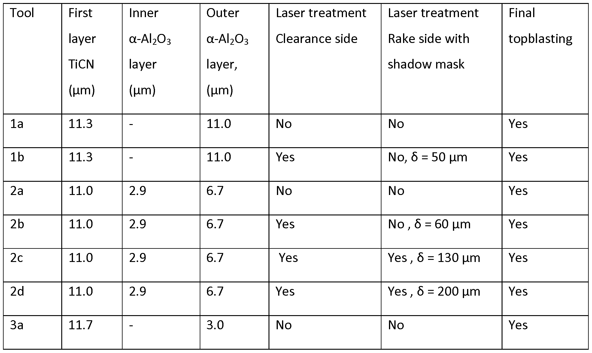
- coated cutting tools were subjected to posttreatments, where lb and 2b were subjected to a laser operation on the clearance side, coated cutting tools 2c, 2d where subjected to a first laser treatment on the clearance side and a second laser treatment with a shadow mask present on the rake side, while tools la, 2a, 3a were not laser treated.
- the laser used was a diode-pumped YAG laser (Violine 3 from Laservall) operated at 10 W, 1064 nm, a pulse length of 6 ns (measured at 10 kHz) and a repetition frequency of 20 kHz.
- a focal lens with 254 mm focal length was used resulting in a spot size of 100 ⁇ .
- the laser beam was directed in an orthogonal direction to the clearance side at the nose of the cutting tool and an area of 6x2 mm was irradiated in a raster scan with scan lines having a width of 0.1 mm in parallel and orthogonally to the cutting edge, as schematically illustrated with arrow in FIG. 2.
- the beam was displaced with a speed of 750 mm/s and two passes were made.
- FIG. 2 also schematically illustrates an inscribed ellipse with the 2W axis and the 2H axis and the total coating thickness T.
- the distance ⁇ is also shown in Fig. 2, defined as a distance ⁇ from the exposed cutting edge to the edge of the remaining outer ⁇ - ⁇ 2 0 3 layer as seen from the rake side.
- the distance ⁇ was measured by light optical microscopy in a direction orthogonal to the rake side when the cutting tool is resting on a flat surface opposite the rake side.
- the direction R is a direction ortigonal to the width of the cutting edge.
- the width is measured in the same plane and direction as ⁇ .
- the laser lift-off treatment on the clearance side remove the outer ⁇ - ⁇ 2 0 3 layer on the whole width of the edge of the coated cutting tools, and into the rake side, to a distance ⁇ of about 50 ⁇ of tool lb and about 60 ⁇ for tool 2b.
- a cemented carbide shadow mask was used to define the extension of such a removal in a controlled way.
- the shadow mask protects the layers beneath the mask from being exposed of the laser and thereby the outer ⁇ - ⁇ 2 0 3 layer is not being removed from the area beneath the shadow mask.
- Different shadow masks were used in order to enable different distances ⁇ of the outer ⁇ - ⁇ 2 0 3 layer being removed from edge and into the rake side in the laser process on the rake side.
- the distance ⁇ is measured as the distance from the exposed cutting edge as seen from the rake side as disclosed above, and to the edge of the remaining outer ⁇ - ⁇ 2 0 3 layer.
- the laser treatment were for all the examples extended in the direction of the cutting edge to a position outside the cutting depth.
- Four different exposed distances ⁇ from the edge into the rake side were thus manufactured, about 50 ⁇ , about 60 ⁇ , about 130 ⁇ and about 200 ⁇ .
- Tools provided with coating 1 was subjected to a laser operation removing the outer ⁇ - ⁇ 2 0 3 layer on the rake side from the edge to a distances ⁇ of about 50 ⁇ .
- Tools provided with coating 2 were subjected to a laser operation removing the outer ⁇ - ⁇ 2 0 3 layer on the rake side from the edge to a distances ⁇ of about 60 ⁇ , about 130 ⁇ and about 200 ⁇ respectively.
- the resulting average disctance ⁇ for the laser treated tool lb, 2b, 2c and 2d is shown in Table 2.
- a wet blasting was performed on the rake sides of all the cutting tools, here called a final top blasting.
- the aim of this treatment was to introduce compressive stresses into the outermost coatings and thereby increase the edge toughness of the tools.
- the aim was further to smoothen the edge of the remaining outer ⁇ - ⁇ 2 0 3 layer and to remove the intermediate layer in the exposed surface area.
- the blaster slurry consisted of 20 vol-% alumina grits in water and an angle of 90° between the rake side of the cutting insert and the direction of the blaster slurry.
- the distance between the gun nozzle and the surface of the insert was about 145 mm.
- the pressure of the slurry to the gun was 1.8 bar for all samples, while the pressure of air to the gun was 2.1 bar for all tools.
- the alumina grits were F220 mesh (FEPA 42-1:2006).
- the time for blasting per area unit was about 4 seconds.
- a summary of the coated cutting tools la, lb, 2a, 2b, 2c, 2d, and 3a manufactured in Example 7 is presented in Table 3.
- FIG. 6 A cross sectional image of the coated cutting tool lb is shown in Fig. 6 and a corresponding image of the coated cutting tool 2d is shown in Fig. 7. Table 3.
- Example 7 The coated cutting tools la, 2a, 2b, 2c, 2d, 3a of Example 7 were tested in a toughness test.
- the work piece material consist of two carbon steel bars (Fe 360BFN), mounted parallel to each other with a distance between them. In longitudinal turning of this work piece the cutting tool will be exposed to two interruptions per revolution. In this test the toughness of the cutting tool has shown to be critical for its lifetime. The following cutting data was used;
- the cutting feed was increased continuously during the test.
- the start value was 0.15 mm/revolution. After 1 minute of cutting the feed value was 0.20 mm/revolution and after 2 minutes of cutting, the feed value was 0.25 mm/revolution, and after 3 minutes of cutting the feed value was 0,30mm/revolution.
- An equipment for measuring the cutting forces was used. When an insert breakage occurred the cutting force increased clearly and the machine was stopped. 25 cutting edges were evaluated per cutting tool variant. The actual value of the cutting feed at fracture for each one of the 25 cutting edges was registered. The values were sorted from the lowest fracture feed value to the highest, for each cutting tool variant.
- the wear performance is shown in Table 4, presenting the feed at fracture for edge number 6, the median value of all 25 edges and the value for edge number 20.
- the tool 3a comprising the relatively thin outer ⁇ - ⁇ 2 0 3 layer shows the best performance in this test and the tool 2a comprising a relativey thick outer ⁇ - ⁇ 2 0 3 layer shows a shorter time to fracture.
- the laser treated tool 2d shows a edge toughness performance in between the performance of tool 3a and tool 2a.
- the edge line toughness is slightly better for the laser treated tool 2d as compared to the tool 2a with a relatively thick outer ct- Al 2 0 3 layer on the edge.
- Tool 2d performs slightly better than the tools 2b and la in this test.
- the crater wear area in this test started at a distance of about 300 ⁇ from the exposed cutting edge, measured by light optical microscope as the shortest distance in the plane of the rake side.
- flank wear In analyzing the flank wear, the distance from the edge line to the bottom of the flank wear pattern, as seen perpendicular to the clearance side, was measured using a light optical microscope. In analyzing the crater wear, the area of removed material on the rake side (crater wear) was measured, using a light optical microscope. The wear of each cutting tool was evaluated after 4 minutes cutting in the light optical microscope. The cutting process was then continued with a measurement after each 4 minutes run. Beside crater wear, flank wear and build up edge were also observed. The results are shown in Table 6.
- the cutting tools la and 2a i.e. the tools with the relatively thickest aluminium oxide over the edge, showed the highest resistance to flank wear.
- the cutting tools 2b, 2c, 2d showed a higher flank wear resistance as compared to cutting tools lb.
- the cutting tool 2d showed a higher wear resistance compared to 2b.
- the crater wear area started at a distance of about 300 ⁇ from the exposed cutting edge, measured as the shortest distance in the plane of the rake side.
- Insert style CN MG120408-PM Water miscible metal working fluid was used.
- One cutting edge per cutting tool was evaluated.
- the area of removed material on the rake side (crater wear) was measured, using a light optical microscope.
- the wear of each cutting tool was evaluated after 4 minutes cutting in the light optical microscope. The cutting process was then continued with a measurement after each 4 minutes run. Beside crater wear, flank wear and build up edge was also observed. The results after 22 minutes are shown in Table 7.
- the flank wear resistance is slightly higher for the cutting tool 2d as compared to the cutting tools 2b and 2c.
- the reason for this might be that a laser lift off close to the edge effects the shape and micro geometry of the cutting edge.
- the crater wear area in this test started at a distance of about 300 ⁇ from the exposed cutting edge, measured as the shortest distance in the plane of the rake side.
Landscapes
- Chemical & Material Sciences (AREA)
- Engineering & Computer Science (AREA)
- Mechanical Engineering (AREA)
- Metallurgy (AREA)
- Materials Engineering (AREA)
- Chemical Kinetics & Catalysis (AREA)
- Organic Chemistry (AREA)
- Inorganic Chemistry (AREA)
- General Chemical & Material Sciences (AREA)
- Ceramic Engineering (AREA)
- Physics & Mathematics (AREA)
- Plasma & Fusion (AREA)
- Cutting Tools, Boring Holders, And Turrets (AREA)
- Chemical Vapour Deposition (AREA)
- Drilling Tools (AREA)
Abstract
Description




Claims
Priority Applications (6)
| Application Number | Priority Date | Filing Date | Title |
|---|---|---|---|
| RU2015130231A RU2648719C2 (en) | 2012-12-21 | 2013-12-20 | Coated cutting tool and method for manufacturing same |
| KR1020157016429A KR102178612B1 (en) | 2012-12-21 | 2013-12-20 | Coated cutting tool and method for manufacturing the same |
| CN201380066618.1A CN104870686A (en) | 2012-12-21 | 2013-12-20 | Coated cutting tool and method for manufacturing the same |
| JP2015548629A JP6324990B2 (en) | 2012-12-21 | 2013-12-20 | Coated cutting tool and manufacturing method thereof |
| US14/653,627 US9950373B2 (en) | 2012-12-21 | 2013-12-20 | Coated cutting tool and method for manufacturing the same |
| EP13815742.5A EP2935647B1 (en) | 2012-12-21 | 2013-12-20 | Coated cutting tool and method for manufacturing the same |
Applications Claiming Priority (2)
| Application Number | Priority Date | Filing Date | Title |
|---|---|---|---|
| SE1200782 | 2012-12-21 | ||
| SE1200782-9 | 2012-12-21 |
Publications (1)
| Publication Number | Publication Date |
|---|---|
| WO2014096348A1 true WO2014096348A1 (en) | 2014-06-26 |
Family
ID=49917073
Family Applications (1)
| Application Number | Title | Priority Date | Filing Date |
|---|---|---|---|
| PCT/EP2013/077665 Ceased WO2014096348A1 (en) | 2012-12-21 | 2013-12-20 | Coated cutting tool and method for manufacturing the same |
Country Status (7)
| Country | Link |
|---|---|
| US (1) | US9950373B2 (en) |
| EP (1) | EP2935647B1 (en) |
| JP (1) | JP6324990B2 (en) |
| KR (1) | KR102178612B1 (en) |
| CN (1) | CN104870686A (en) |
| RU (1) | RU2648719C2 (en) |
| WO (1) | WO2014096348A1 (en) |
Families Citing this family (16)
| Publication number | Priority date | Publication date | Assignee | Title |
|---|---|---|---|---|
| KR101537718B1 (en) * | 2014-04-23 | 2015-07-20 | 한국야금 주식회사 | Cutting tools having coated layer removed partly |
| US11376675B2 (en) * | 2014-04-23 | 2022-07-05 | Korloy Inc. | Cutting tool having partially-removed film formed thereon |
| DE102015213755A1 (en) * | 2015-07-21 | 2017-01-26 | Kennametal Inc. | Method for producing a cutting tool and cutting tool |
| DE102015222491B4 (en) * | 2015-11-13 | 2023-03-23 | Kennametal Inc. | Cutting tool and method of making same |
| FR3046097B1 (en) * | 2015-12-29 | 2018-07-13 | Mecachrome France | PROCESS FOR SHARPENING MACHINING PLATE AND CORRESPONDING STITCHED PLATE. |
| CN107570772B (en) * | 2017-09-07 | 2020-04-28 | 株洲钻石切削刀具股份有限公司 | A cutting insert with several different coatings on the surface |
| CN107775538A (en) * | 2017-09-15 | 2018-03-09 | 富耐克超硬材料股份有限公司 | Diamond-coated tools and its post-processing approach |
| JP6928248B2 (en) * | 2017-09-29 | 2021-09-01 | 三菱マテリアル株式会社 | Diamond coated rotary cutting tool |
| CN109158625A (en) * | 2018-08-14 | 2019-01-08 | 株洲钻石切削刀具股份有限公司 | A kind of flank has the cutting tip of different coating |
| CN114222643B (en) * | 2019-08-30 | 2024-12-31 | 山特维克科洛曼特公司 | Method for treating coated cutting tools |
| CN110976992B (en) * | 2019-12-13 | 2024-10-29 | 深圳富联精匠科技有限公司 | Cutting tool |
| CN115052700B (en) * | 2020-02-05 | 2024-11-29 | 三菱综合材料株式会社 | Method for manufacturing cutting tool |
| KR102450097B1 (en) * | 2020-11-16 | 2022-10-05 | 한국야금 주식회사 | Hard film for cutting tools |
| JP2024139281A (en) * | 2023-03-27 | 2024-10-09 | 株式会社タンガロイ | Coated cutting tool |
| CN118385629B (en) * | 2024-06-28 | 2024-09-10 | 株洲钻石切削刀具股份有限公司 | Cutting blade with annular reinforcing coating on side face |
| CN118385632B (en) * | 2024-06-28 | 2024-09-17 | 株洲钻石切削刀具股份有限公司 | Cutting blade with convex coating unit on rear surface |
Citations (5)
| Publication number | Priority date | Publication date | Assignee | Title |
|---|---|---|---|---|
| US5776588A (en) | 1994-04-27 | 1998-07-07 | Sumitomo Electric Industries, Ltd. | Coated hard alloy tool |
| US5861210A (en) | 1994-07-20 | 1999-01-19 | Sandvik Ab | Aluminum oxide coated tool |
| US20060029831A1 (en) * | 2004-07-13 | 2006-02-09 | Sandvik Intellectual Property Ab | Coated insert and method of making same |
| US7431747B2 (en) | 2003-07-15 | 2008-10-07 | Kennametal Inc. | Cutting tool and method of reducing the width of wear mark on a cutting tool |
| JP2012223872A (en) * | 2011-04-21 | 2012-11-15 | Sumitomo Electric Ind Ltd | Coated cutting tool |
Family Cites Families (14)
| Publication number | Priority date | Publication date | Assignee | Title |
|---|---|---|---|---|
| US4984940A (en) * | 1989-03-17 | 1991-01-15 | Kennametal Inc. | Multilayer coated cemented carbide cutting insert |
| SE464818B (en) * | 1989-06-16 | 1991-06-17 | Sandvik Ab | COVERED SHOULD BE CUTTING |
| SE502174C2 (en) * | 1993-12-23 | 1995-09-04 | Sandvik Ab | Methods and articles when coating a cutting tool with an alumina layer |
| US5722803A (en) | 1995-07-14 | 1998-03-03 | Kennametal Inc. | Cutting tool and method of making the cutting tool |
| JP3814051B2 (en) * | 1996-06-12 | 2006-08-23 | 住友電工ハードメタル株式会社 | Coated hard alloy tool |
| JP3368289B2 (en) | 1996-06-25 | 2003-01-20 | キヤノン化成株式会社 | Cylindrical member holder and processing apparatus and method provided with the cylindrical member holder |
| KR100688923B1 (en) * | 2000-07-12 | 2007-03-09 | 스미토모덴키고교가부시키가이샤 | Sheath cutting tool |
| SE526603C3 (en) * | 2003-01-24 | 2005-11-16 | Sandvik Intellectual Property | Coated cemented carbide insert |
| WO2006103982A1 (en) * | 2005-03-29 | 2006-10-05 | Sumitomo Electric Hardmetal Corp. | Edge replacement cutter tip and method of manufacturing the same |
| US7695222B2 (en) * | 2005-10-21 | 2010-04-13 | Sumitomo Electric Hardmetal Corp. | Indexable insert |
| JP4797608B2 (en) | 2005-12-02 | 2011-10-19 | 三菱マテリアル株式会社 | Surface-coated cutting insert and manufacturing method thereof |
| SE529855C2 (en) | 2005-12-30 | 2007-12-11 | Sandvik Intellectual Property | Coated cemented carbide inserts and ways of making this |
| JP4973880B2 (en) | 2008-11-12 | 2012-07-11 | 住友電工ハードメタル株式会社 | Surface coated cutting tool |
| JP2012192480A (en) * | 2011-03-16 | 2012-10-11 | Mitsubishi Materials Corp | Surface-coated cutting tool with hard coating layer for exhibiting excellent abnormal damage resistance |
-
2013
- 2013-12-20 EP EP13815742.5A patent/EP2935647B1/en active Active
- 2013-12-20 RU RU2015130231A patent/RU2648719C2/en not_active IP Right Cessation
- 2013-12-20 CN CN201380066618.1A patent/CN104870686A/en active Pending
- 2013-12-20 US US14/653,627 patent/US9950373B2/en active Active
- 2013-12-20 KR KR1020157016429A patent/KR102178612B1/en active Active
- 2013-12-20 WO PCT/EP2013/077665 patent/WO2014096348A1/en not_active Ceased
- 2013-12-20 JP JP2015548629A patent/JP6324990B2/en active Active
Patent Citations (5)
| Publication number | Priority date | Publication date | Assignee | Title |
|---|---|---|---|---|
| US5776588A (en) | 1994-04-27 | 1998-07-07 | Sumitomo Electric Industries, Ltd. | Coated hard alloy tool |
| US5861210A (en) | 1994-07-20 | 1999-01-19 | Sandvik Ab | Aluminum oxide coated tool |
| US7431747B2 (en) | 2003-07-15 | 2008-10-07 | Kennametal Inc. | Cutting tool and method of reducing the width of wear mark on a cutting tool |
| US20060029831A1 (en) * | 2004-07-13 | 2006-02-09 | Sandvik Intellectual Property Ab | Coated insert and method of making same |
| JP2012223872A (en) * | 2011-04-21 | 2012-11-15 | Sumitomo Electric Ind Ltd | Coated cutting tool |
Also Published As
| Publication number | Publication date |
|---|---|
| JP6324990B2 (en) | 2018-05-16 |
| EP2935647A1 (en) | 2015-10-28 |
| RU2648719C2 (en) | 2018-03-28 |
| KR102178612B1 (en) | 2020-11-13 |
| CN104870686A (en) | 2015-08-26 |
| EP2935647B1 (en) | 2019-08-14 |
| US9950373B2 (en) | 2018-04-24 |
| KR20150095695A (en) | 2015-08-21 |
| JP2016502936A (en) | 2016-02-01 |
| RU2015130231A (en) | 2017-01-30 |
| US20150298215A1 (en) | 2015-10-22 |
Similar Documents
| Publication | Publication Date | Title |
|---|---|---|
| US9950373B2 (en) | Coated cutting tool and method for manufacturing the same | |
| US9849516B2 (en) | Coated cutting tool and method for manufacturing the same | |
| JP5872747B1 (en) | Surface coated cutting tool | |
| CN102639267B (en) | Surface coating cutting tool | |
| JP5670661B2 (en) | Coated cutting tool insert | |
| KR102107878B1 (en) | Surface-coated cutting tool | |
| US9844816B2 (en) | Surface-coated cutting tool | |
| EP2074241B1 (en) | Coated cutting tool | |
| JP6507456B2 (en) | Method of manufacturing surface coated cutting tool | |
| EP2909359A1 (en) | Coated cutting tool with patterned surface area | |
| JP2009028894A (en) | Coated cutting tool | |
| JP6507457B2 (en) | Method of manufacturing surface coated cutting tool | |
| KR101503128B1 (en) | Surface-coated cutting tool | |
| KR101590203B1 (en) | Oxide coated cutting insert | |
| JP2020522396A (en) | Coated cutting tools | |
| JP5858363B2 (en) | Substrate for cutting tool and surface-coated cutting tool including the same | |
| JP4084678B2 (en) | Surface-coated cutting tool and manufacturing method thereof | |
| CN113195135B (en) | Cutting Tools |
Legal Events
| Date | Code | Title | Description |
|---|---|---|---|
| 121 | Ep: the epo has been informed by wipo that ep was designated in this application |
Ref document number: 13815742 Country of ref document: EP Kind code of ref document: A1 |
|
| WWE | Wipo information: entry into national phase |
Ref document number: 14653627 Country of ref document: US |
|
| ENP | Entry into the national phase |
Ref document number: 20157016429 Country of ref document: KR Kind code of ref document: A Ref document number: 2015548629 Country of ref document: JP Kind code of ref document: A |
|
| NENP | Non-entry into the national phase |
Ref country code: DE |
|
| WWE | Wipo information: entry into national phase |
Ref document number: 2013815742 Country of ref document: EP |
|
| ENP | Entry into the national phase |
Ref document number: 2015130231 Country of ref document: RU Kind code of ref document: A |
|
| REG | Reference to national code |
Ref country code: BR Ref legal event code: B01A Ref document number: 112015015006 Country of ref document: BR |
|
| ENP | Entry into the national phase |
Ref document number: 112015015006 Country of ref document: BR Kind code of ref document: A2 Effective date: 20150622 |