WO2014097367A1 - ヒートシャッタ装置 - Google Patents
ヒートシャッタ装置 Download PDFInfo
- Publication number
- WO2014097367A1 WO2014097367A1 PCT/JP2012/082655 JP2012082655W WO2014097367A1 WO 2014097367 A1 WO2014097367 A1 WO 2014097367A1 JP 2012082655 W JP2012082655 W JP 2012082655W WO 2014097367 A1 WO2014097367 A1 WO 2014097367A1
- Authority
- WO
- WIPO (PCT)
- Prior art keywords
- electronic device
- heat shutter
- heat
- shutter
- rack
- Prior art date
- Legal status (The legal status is an assumption and is not a legal conclusion. Google has not performed a legal analysis and makes no representation as to the accuracy of the status listed.)
- Ceased
Links
Images



Classifications
-
- H—ELECTRICITY
- H05—ELECTRIC TECHNIQUES NOT OTHERWISE PROVIDED FOR
- H05K—PRINTED CIRCUITS; CASINGS OR CONSTRUCTIONAL DETAILS OF ELECTRIC APPARATUS; MANUFACTURE OF ASSEMBLAGES OF ELECTRICAL COMPONENTS
- H05K7/00—Constructional details common to different types of electric apparatus
- H05K7/20—Modifications to facilitate cooling, ventilating, or heating
- H05K7/20009—Modifications to facilitate cooling, ventilating, or heating using a gaseous coolant in electronic enclosures
- H05K7/20136—Forced ventilation, e.g. by fans
- H05K7/20181—Filters; Louvers
-
- H—ELECTRICITY
- H05—ELECTRIC TECHNIQUES NOT OTHERWISE PROVIDED FOR
- H05K—PRINTED CIRCUITS; CASINGS OR CONSTRUCTIONAL DETAILS OF ELECTRIC APPARATUS; MANUFACTURE OF ASSEMBLAGES OF ELECTRICAL COMPONENTS
- H05K7/00—Constructional details common to different types of electric apparatus
- H05K7/20—Modifications to facilitate cooling, ventilating, or heating
- H05K7/20709—Modifications to facilitate cooling, ventilating, or heating for server racks or cabinets; for data centers, e.g. 19-inch computer racks
- H05K7/20718—Forced ventilation of a gaseous coolant
- H05K7/20736—Forced ventilation of a gaseous coolant within cabinets for removing heat from server blades
Definitions
- the present invention relates to a heat shutter device, and more particularly to a technique for preventing warm air discharged from the back of an electronic device from flowing back to the front of the electronic device.
- electronic devices mounted in the rack are generally structured such that air is sucked from the front and exhausted from the back.
- some electronic devices suck and exhaust air from the side of the electronic device.
- heat fever intake / exhaust is disturbed, a heat shutter cannot be installed.
- an object of the present invention is to provide a heat shutter device capable of easily taking a reflux prevention measure in accordance with an installation state of electronic devices in a side space in a rack.
- a heat shutter device is a heat shutter device provided in a rack in which a plurality of electronic devices are mounted in the height direction of the electronic device while securing side spaces for cable wiring on both sides thereof.
- a heat shutter that prevents the recirculation of warm air exhausted from the air through the side space to the front of the electronic device for each electronic device, and a connecting bar provided in the rack in the height direction of the electronic device via the base portion, And a locking portion that is provided on one side of the heat shutter and is rotatably locked to the connecting bar.
- the heat shutter has an elastic member that closes a gap with the electronic device on the back surface.
- the electronic device includes an electronic device having an intake port or an exhaust port on the side surface
- the electronic device having the intake port or the exhaust port on the side surface is connected to the intake port or the exhaust port without attaching the heat shutter to the electronic device. Or it is preferable to attach an exhaust duct.
- the elastic member is made of a flame retardant sponge.
- a plurality of electronic devices mounted in the height direction of the electronic device has a first electronic device having an intake port on the front surface and an exhaust port on the rear surface, and a second electronic device having an intake port or an exhaust port on the side surface.
- the second electronic device is attached with an intake duct or an exhaust duct that communicates the intake port or the exhaust port with the front surface or the back surface of the second electronic device instead of the heat shutter.
- the present invention it is possible to provide a heat shutter device capable of easily taking a reflux prevention measure in accordance with the installation state of the electronic device in the side space in the rack.
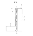
- It is a figure which shows a heat shutter (a) is a front view, (b) is a side view.
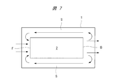
- a plurality of electronic devices 2 such as servers are mounted in a height direction via angles 3 and metal fittings in a cabinet type rack 1.
- a cable 4 is connected to each electronic device 2, and the cable 4 passes through both sides of the electronic device 2 and is concentrated in a space on the back side.
- side spaces S are provided on both sides of the electronic device 2 in the rack 1.
- the electronic device 2 is configured to take in air from the front surface F and to discharge air warmed inside the electronic device 2 from the back surface B in order to release generated heat. Therefore, in the electronic device 2, warm exhaust (warm air) discharged from the back surface B of the electronic device 2 passes through the side space S to the front surface F of the electronic device 2 and is taken into the electronic device 2 again. Reflux occurs. In order to prevent the occurrence of this reflux, a heat shutter device 5 is provided in the side space S.
- the heat shutter device 5 is disposed on both sides of the front surface F of the electronic device 2.
- a plate-like heat shutter (synonymous with a heat shutter plate) 7 that prevents the warm air discharged from the back surface B of the electronic device 2 from flowing back to the front surface F of the electronic device 2 through the side space S for each electronic device 2;
- a connecting bar 9 provided on the rack 1 via a base portion 8 for connecting the heat shutter 7 and a heat shutter 7 provided on the rack 1 and detachably locked to the connecting bar 9 so that the heat shutter 7 can be rotated.
- a locking portion 10 to be supported.
- the base portion 8 is formed in a vertically long rectangular plate shape having a height that is a multiple of the height of the electronic device 2 and four times the height in the example of FIG.
- a metal is preferable.
- the base portion of the base portion 8 is fixed to the frame or side panel of the rack 1.
- screws are preferably used as fixing means
- magnets are preferably used as fixing means.
- the connecting bar 9 is made of a metal rod shaft having a circular cross section, and is provided on the outer surface of the tip portion of the base portion 8 by fixing means such as welding and screwing over the entire length in the height direction. It is preferable for manufacturing that the connecting bar 9 has the same length as the height of the base portion 8.
- the connecting bar 9 may be divided for each heat shutter 7.
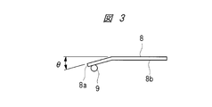
- the base part 8 is formed with a relief groove 11 for avoiding buffering with the engaging part 10 of the heat shutter 7. Further, in order to facilitate the mounting of the heat shutter 7, the tip 8a side of the base 8 is bent outward at a predetermined angle ⁇ with respect to the base 8b as shown in FIG. 3 or FIG. Is preferred.
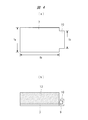
- the heat shutter 7 is made of a metal plate having a predetermined vertical width fa and a horizontal width fb that covers the side space S from the front side of the electronic device 2 as shown in FIGS. .
- the vertical width fa of the heat shutter 7 is the height of one unit of the electronic device 2.
- the horizontal width fb of the heat shutter 7 is a width between the electronic device 2 and the frame or side panel of the rack 1.
- a locking portion 10 that is detachably locked to the connecting bar 9 and rotatably supports the heat shutter 7.
- the locking portion 10 has a vertical width fc that is narrower than the vertical width fa of the heat shutter 7, and has a U-shaped cross section or a U-shaped cross section so as to surround the connection bar 9 with the elastic member 12. It is bent.
- the heat shutter 7 has an elastic member 12 that closes the gap with the electronic device 2 corresponding to the unevenness of the cable 4 or the like.
- the elastic member 12 is formed in a block shape or a rectangular parallelepiped shape having substantially the same size and a predetermined thickness as the plate-like portion excluding the locking portion 10 of the heat shutter 7.
- the elastic member 12 is preferably made of a flame retardant sponge so as to close the gap with the electronic device 2 corresponding to the unevenness of the cable 4 and the like and to withstand the heat generated from the electronic device 2.
- the elastic member 12 is affixed to the inner surface of the heat shutter 7 via an adhesive or an adhesive sheet.
- the electronic devices 2 stacked in the height direction have a first electronic device 2 a having an intake port (not shown) on the front surface and an exhaust port (not shown) on the rear surface, and a side surface. And a second electronic device 2b having an intake port 13 or an exhaust port.
- the second electronic device 2b having the intake port 13 or the exhaust port is included in the side surface as described above, the second electronic device 2x is replaced with the heat shutter 7, and the side surface of the second electronic device 2 is inhaled.
- An intake duct 14 or an exhaust duct (not shown) that connects the port 13 or the exhaust port and the front surface or the back surface of the second electronic device 2b is attached.
- the intake duct 14 has an inner side surface 14a and a front end surface 14b facing the side surfaces of the second electronic device 2x
- the exhaust duct has an inner side surface and a rear end surface open.
- the front end portion of the intake duct 14 or the rear end portion of the exhaust duct is fitted into a rectangular opening 15 surrounded by the second electronic device 2b, the base portion 8 and the heat shutter 7. Installed in condition.
- the heat shutter device 5 having the above-described configuration, it is possible to take a reflux prevention measure according to the installation state of the electronic device 2 in the side space S in the rack 1, and to suppress an increase in the suction temperature of the electronic device 2.
- the heat shutter device 5 that can improve the durability of the device 2 can be provided.
- the heat shutter 7 has a unit size and has a structure in which an elastic member 12 made of a flame-retardant sponge is attached to the back surface, and the engaging portion 10 is hooked on the connecting bar 9 of the base portion 8 so as to be rotatably supported.
- the installation angle with the connecting bar 9 of the heat shutter 7 as a fulcrum can be arbitrarily adjusted corresponding to the amount of the cable 4 in units of one unit, and the heat shutter 7, the electronic device 2, It is possible to prevent the circulation of exhaust gas by sufficiently reducing the gap.
- the heat shutter 7 has the latching
- the intake duct 14 is structured to take in air from the front side of the rack 1, and the exhaust duct is structured to exhaust from the back side of the rack 1, and is connected to the intake port 13 or the exhaust port arranged on the side surface of the electronic device.
- the intake duct or the exhaust duct can be selected, the electronic apparatus can be efficiently cooled, and the durability of the electronic apparatus can be improved.
- server racks are used not only in data centers but also in company server rooms, etc., if there is a side space in the server rack, it is necessary to take measures to prevent the return of warm air in the side space. It can be used.
- the present invention can be applied to an electronic device that sucks and exhausts air from the side such as a network device. Therefore, measures can be taken according to the installed electronic device. Moreover, since the electronic devices such as servers accommodated in the server rack can be efficiently cooled by preventing the reflux, there is also an energy saving effect, and the present invention can be used effectively. .
Landscapes
- Engineering & Computer Science (AREA)
- Microelectronics & Electronic Packaging (AREA)
- Physics & Mathematics (AREA)
- Thermal Sciences (AREA)
- Computer Hardware Design (AREA)
- General Engineering & Computer Science (AREA)
- Cooling Or The Like Of Electrical Apparatus (AREA)
Abstract
Description
2 電子機器
2a 第1の電子機器
2b 第2の電子機器
3 アングル
4 ケーブル
5 ヒートシャッタ装置
S サイドスペース
7 ヒートシャッタ
8 ベース部
8a 先端部
8b 基部
9 連結バー
10 係止部
11 逃げ溝
12 弾性部材
13 吸気口
14 吸気ダクト
14a 内側面
14b 前端面
15 開口部
Claims (4)
- 電子機器をその両側にケーブル配線用のサイドスペースを確保しつつ電子機器の高さ方向に複数搭載するラックに設けられるヒートシャッタ装置であって、
前記電子機器の背面から排気された暖気が前記サイドスペースを通って電子機器の前面に回り込む還流を電子機器毎に阻止するヒートシャッタと、
前記ラックにベース部を介して電子機器の高さ方向に設けられた連結バーと、
前記ヒートシャッタの一側に設けられ、前記連結バーに回動可能に係止される係止部とを備えた、ヒートシャッタ装置。 - 請求項1に記載のヒートシャッタ装置において、
前記ヒートシャッタが、裏面に前記電子機器との間の隙間を塞ぐ弾性部材を有している、ヒートシャッタ装置。 - 請求項2に記載のヒートシャッタ装置において、
前記弾性部材が難燃性のスポンジからなる、ヒートシャッタ装置。 - 請求項1に記載のヒートシャッタ装置において、
前記電子機器の高さ方向に複数搭載された前記電子機器が、前面に吸気口を有し、後面に排気口を有する第1の電子機器と、側面に吸気口または排気口を有する第2の電子機器とを含み、第2の電子機器には前記ヒートシャッタに代えて前記吸気口または排気口と前記第2の電子機器の前面または背面とを連通する吸気ダクトまたは排気ダクトを取付ける、ヒートシャッタ装置。
Priority Applications (4)
| Application Number | Priority Date | Filing Date | Title |
|---|---|---|---|
| US14/652,353 US20150334873A1 (en) | 2012-12-17 | 2012-12-17 | Heat shutter device |
| PCT/JP2012/082655 WO2014097367A1 (ja) | 2012-12-17 | 2012-12-17 | ヒートシャッタ装置 |
| EP12890312.7A EP2934077B1 (en) | 2012-12-17 | 2012-12-17 | Heat shutter device |
| JP2014552766A JP5974113B2 (ja) | 2012-12-17 | 2012-12-17 | ヒートシャッタ装置 |
Applications Claiming Priority (1)
| Application Number | Priority Date | Filing Date | Title |
|---|---|---|---|
| PCT/JP2012/082655 WO2014097367A1 (ja) | 2012-12-17 | 2012-12-17 | ヒートシャッタ装置 |
Publications (1)
| Publication Number | Publication Date |
|---|---|
| WO2014097367A1 true WO2014097367A1 (ja) | 2014-06-26 |
Family
ID=50977756
Family Applications (1)
| Application Number | Title | Priority Date | Filing Date |
|---|---|---|---|
| PCT/JP2012/082655 Ceased WO2014097367A1 (ja) | 2012-12-17 | 2012-12-17 | ヒートシャッタ装置 |
Country Status (4)
| Country | Link |
|---|---|
| US (1) | US20150334873A1 (ja) |
| EP (1) | EP2934077B1 (ja) |
| JP (1) | JP5974113B2 (ja) |
| WO (1) | WO2014097367A1 (ja) |
Cited By (1)
| Publication number | Priority date | Publication date | Assignee | Title |
|---|---|---|---|---|
| JP2018195652A (ja) * | 2017-05-15 | 2018-12-06 | 河村電器産業株式会社 | 電気機器収納用キャビネット |
Families Citing this family (3)
| Publication number | Priority date | Publication date | Assignee | Title |
|---|---|---|---|---|
| JP6613665B2 (ja) * | 2015-07-10 | 2019-12-04 | 富士通株式会社 | 電子機器 |
| US9801308B2 (en) * | 2016-03-09 | 2017-10-24 | Dell Products Lp | Managing cable connections and air flow in a data center |
| US10433464B1 (en) * | 2016-06-06 | 2019-10-01 | ZT Group Int'l, Inc. | Air duct for cooling a rear-mounted switch in a rack |
Citations (5)
| Publication number | Priority date | Publication date | Assignee | Title |
|---|---|---|---|---|
| JPH02187984A (ja) * | 1989-01-13 | 1990-07-24 | Fujitsu Ltd | 磁気ディスク装置 |
| JP2007305754A (ja) | 2006-05-11 | 2007-11-22 | Kawamura Electric Inc | キャビネットラックのヒートシャッタ構造 |
| JP2008117876A (ja) * | 2006-11-02 | 2008-05-22 | Kawamura Electric Inc | 冷気循環システム |
| JP2008130714A (ja) * | 2006-11-20 | 2008-06-05 | Nec Computertechno Ltd | ラックキャビネット |
| JP2012248565A (ja) * | 2011-05-25 | 2012-12-13 | Nec Computertechno Ltd | 電子機器の冷却構造 |
Family Cites Families (29)
| Publication number | Priority date | Publication date | Assignee | Title |
|---|---|---|---|---|
| US6788535B2 (en) * | 2002-12-12 | 2004-09-07 | 3M Innovative Properties Company | Outdoor electronic equipment cabinet |
| US7031154B2 (en) * | 2003-04-30 | 2006-04-18 | Hewlett-Packard Development Company, L.P. | Louvered rack |
| US7033267B2 (en) * | 2003-05-13 | 2006-04-25 | American Power Conversion Corporation | Rack enclosure |
| US20050276017A1 (en) * | 2004-06-10 | 2005-12-15 | Farid Aziz | Common plenum and air intake airflow management for telecom equipment |
| JP2006059448A (ja) * | 2004-08-20 | 2006-03-02 | Hitachi Ltd | ディスクアレイ装置 |
| GB2419038B (en) * | 2004-09-23 | 2010-03-31 | Trox | Cooling methods and apparatus |
| US7113401B2 (en) * | 2004-10-25 | 2006-09-26 | International Business Machines Corporation | System for airflow management in electronic enclosures |
| US7804685B2 (en) * | 2005-09-19 | 2010-09-28 | Chatsworth Products, Inc. | Ducted exhaust equipment enclosure |
| JP2007179655A (ja) * | 2005-12-28 | 2007-07-12 | Hitachi Ltd | ディスクアレイ装置 |
| US20070159791A1 (en) * | 2006-01-11 | 2007-07-12 | Lucent Technologies Inc. | Low-profile articulated electronics enclosure with improved air coolant system |
| US8257155B2 (en) * | 2006-01-20 | 2012-09-04 | Chatsworth Products, Inc. | Selectively routing air within an electronic equipment enclosure |
| US7595985B2 (en) * | 2006-06-19 | 2009-09-29 | Panduit Corp. | Network cabinet with thermal air flow management |
| US7564685B2 (en) * | 2006-12-29 | 2009-07-21 | Google Inc. | Motherboards with integrated cooling |
| US7710720B2 (en) * | 2007-01-23 | 2010-05-04 | Fujitsu Limited | Electronic device and fire protecting mechanism of the electronic device |
| JP5030631B2 (ja) * | 2007-03-22 | 2012-09-19 | 富士通株式会社 | 情報機器の冷却システム |
| US8009430B2 (en) * | 2007-05-17 | 2011-08-30 | International Business Machines Corporation | Techniques for data center cooling |
| US7643291B2 (en) * | 2007-08-30 | 2010-01-05 | Afco Systems | Cabinet for electronic equipment |
| US7907402B2 (en) * | 2007-11-09 | 2011-03-15 | Panduit Corp. | Cooling system |
| US20090122483A1 (en) * | 2007-11-13 | 2009-05-14 | International Business Machines Corporation | Water-assisted air cooling for a row of cabinets |
| US20090255653A1 (en) * | 2008-04-11 | 2009-10-15 | Dell Products L.P. | System and Method for Cooling a Rack |
| JP4607203B2 (ja) * | 2008-04-28 | 2011-01-05 | 株式会社日立製作所 | ディスクアレイ装置 |
| US8040693B2 (en) * | 2008-10-02 | 2011-10-18 | Panduit Corp. | Universal expandable patch panel bracket |
| US8081459B2 (en) * | 2008-10-17 | 2011-12-20 | Cray Inc. | Air conditioning systems for computer systems and associated methods |
| US8279602B2 (en) * | 2009-10-14 | 2012-10-02 | Commscope, Inc. | Communications cabinet with projectile resistant vents |
| US8164897B2 (en) * | 2010-02-19 | 2012-04-24 | International Business Machines Corporation | Airflow recirculation and cooling apparatus and method for an electronics rack |
| US8154867B2 (en) * | 2010-03-10 | 2012-04-10 | Ciena Corporation | High density switching platform with interbay connections arrangement |
| US8203837B2 (en) * | 2010-03-31 | 2012-06-19 | Hewlett-Packard Developmet Company, L.P. | Cooling system |
| US9313927B2 (en) * | 2010-11-08 | 2016-04-12 | Chatsworth Products, Inc. | Header panel assembly for preventing air circulation above electronic equipment enclosure |
| US8576570B2 (en) * | 2011-03-21 | 2013-11-05 | NCS Technologies, Inc. | Adaptive computing system with modular control, switching, and power supply architecture |
-
2012
- 2012-12-17 JP JP2014552766A patent/JP5974113B2/ja not_active Expired - Fee Related
- 2012-12-17 US US14/652,353 patent/US20150334873A1/en not_active Abandoned
- 2012-12-17 WO PCT/JP2012/082655 patent/WO2014097367A1/ja not_active Ceased
- 2012-12-17 EP EP12890312.7A patent/EP2934077B1/en not_active Not-in-force
Patent Citations (5)
| Publication number | Priority date | Publication date | Assignee | Title |
|---|---|---|---|---|
| JPH02187984A (ja) * | 1989-01-13 | 1990-07-24 | Fujitsu Ltd | 磁気ディスク装置 |
| JP2007305754A (ja) | 2006-05-11 | 2007-11-22 | Kawamura Electric Inc | キャビネットラックのヒートシャッタ構造 |
| JP2008117876A (ja) * | 2006-11-02 | 2008-05-22 | Kawamura Electric Inc | 冷気循環システム |
| JP2008130714A (ja) * | 2006-11-20 | 2008-06-05 | Nec Computertechno Ltd | ラックキャビネット |
| JP2012248565A (ja) * | 2011-05-25 | 2012-12-13 | Nec Computertechno Ltd | 電子機器の冷却構造 |
Cited By (2)
| Publication number | Priority date | Publication date | Assignee | Title |
|---|---|---|---|---|
| JP2018195652A (ja) * | 2017-05-15 | 2018-12-06 | 河村電器産業株式会社 | 電気機器収納用キャビネット |
| JP7043182B2 (ja) | 2017-05-15 | 2022-03-29 | 河村電器産業株式会社 | 電気機器収納用キャビネット |
Also Published As
| Publication number | Publication date |
|---|---|
| US20150334873A1 (en) | 2015-11-19 |
| JP5974113B2 (ja) | 2016-08-23 |
| EP2934077A4 (en) | 2016-10-19 |
| JPWO2014097367A1 (ja) | 2017-01-12 |
| EP2934077A1 (en) | 2015-10-21 |
| EP2934077B1 (en) | 2018-08-15 |
Similar Documents
| Publication | Publication Date | Title |
|---|---|---|
| US11132035B2 (en) | Air directing device | |
| US8520385B2 (en) | Server rack | |
| EP2983461B1 (en) | Cabinet structure and container data centre thereof | |
| US20120049706A1 (en) | Air Flow Management Enclosure | |
| TW201422130A (zh) | 數據中心及其伺服器機櫃 | |
| JP5264432B2 (ja) | ラック間通路遮蔽構造 | |
| JP5974113B2 (ja) | ヒートシャッタ装置 | |
| US8199486B2 (en) | Server cabinet | |
| CN103841799A (zh) | 数据中心及其机柜 | |
| JP6537700B2 (ja) | 電装品モジュール及び空気調和機の室外機 | |
| CN204796001U (zh) | 一种机柜背板局部集中散热装置 | |
| JP4281641B2 (ja) | ラックの冷却装置、ラック、及びコンピュータシステム | |
| JP6182747B2 (ja) | 電気電子機器収納用キャビネット | |
| CN102256460B (zh) | 服务器机柜 | |
| JP3149116U (ja) | コンピュータユニット及びコンピュータ装置 | |
| US20170234573A1 (en) | Baffle for directing air flow in a rack | |
| JP5659373B2 (ja) | 気流制御板 | |
| JP2010168767A (ja) | ラック間通路遮へい構造 | |
| TWI428074B (zh) | 伺服器機櫃 | |
| JP2017112129A (ja) | ファンユニット | |
| TW201442590A (zh) | 機櫃式伺服器及虛擬伺服器機箱 | |
| CN223681396U (zh) | 机柜内设备散热用导风装置、机柜及散热系统 | |
| JP5608878B2 (ja) | 電子機器および熱交換機が収納された収納ラック | |
| JP2013197349A (ja) | 電子機器用ラック | |
| JP6225342B2 (ja) | 盤用冷却装置および盤用冷却装置を備えた盤用キャビネット |
Legal Events
| Date | Code | Title | Description |
|---|---|---|---|
| 121 | Ep: the epo has been informed by wipo that ep was designated in this application |
Ref document number: 12890312 Country of ref document: EP Kind code of ref document: A1 |
|
| ENP | Entry into the national phase |
Ref document number: 2014552766 Country of ref document: JP Kind code of ref document: A |
|
| WWE | Wipo information: entry into national phase |
Ref document number: 14652353 Country of ref document: US |
|
| NENP | Non-entry into the national phase |
Ref country code: DE |
|
| WWE | Wipo information: entry into national phase |
Ref document number: 2012890312 Country of ref document: EP |