WO2014097601A1 - 水素生成装置 - Google Patents
水素生成装置 Download PDFInfo
- Publication number
- WO2014097601A1 WO2014097601A1 PCT/JP2013/007375 JP2013007375W WO2014097601A1 WO 2014097601 A1 WO2014097601 A1 WO 2014097601A1 JP 2013007375 W JP2013007375 W JP 2013007375W WO 2014097601 A1 WO2014097601 A1 WO 2014097601A1
- Authority
- WO
- WIPO (PCT)
- Prior art keywords
- temperature
- raw material
- flow path
- hydrodesulfurizer
- hydrodesulfurization
- Prior art date
- Legal status (The legal status is an assumption and is not a legal conclusion. Google has not performed a legal analysis and makes no representation as to the accuracy of the status listed.)
- Ceased
Links
Images

Classifications
-
- H—ELECTRICITY
- H01—ELECTRIC ELEMENTS
- H01M—PROCESSES OR MEANS, e.g. BATTERIES, FOR THE DIRECT CONVERSION OF CHEMICAL ENERGY INTO ELECTRICAL ENERGY
- H01M8/00—Fuel cells; Manufacture thereof
- H01M8/06—Combination of fuel cells with means for production of reactants or for treatment of residues
- H01M8/0606—Combination of fuel cells with means for production of reactants or for treatment of residues with means for production of gaseous reactants
-
- B—PERFORMING OPERATIONS; TRANSPORTING
- B01—PHYSICAL OR CHEMICAL PROCESSES OR APPARATUS IN GENERAL
- B01J—CHEMICAL OR PHYSICAL PROCESSES, e.g. CATALYSIS OR COLLOID CHEMISTRY; THEIR RELEVANT APPARATUS
- B01J8/00—Chemical or physical processes in general, conducted in the presence of fluids and solid particles; Apparatus for such processes
- B01J8/008—Details of the reactor or of the particulate material; Processes to increase or to retard the rate of reaction
-
- B—PERFORMING OPERATIONS; TRANSPORTING
- B01—PHYSICAL OR CHEMICAL PROCESSES OR APPARATUS IN GENERAL
- B01J—CHEMICAL OR PHYSICAL PROCESSES, e.g. CATALYSIS OR COLLOID CHEMISTRY; THEIR RELEVANT APPARATUS
- B01J19/00—Chemical, physical or physico-chemical processes in general; Their relevant apparatus
- B01J19/24—Stationary reactors without moving elements inside
- B01J19/245—Stationary reactors without moving elements inside placed in series
-
- B—PERFORMING OPERATIONS; TRANSPORTING
- B01—PHYSICAL OR CHEMICAL PROCESSES OR APPARATUS IN GENERAL
- B01J—CHEMICAL OR PHYSICAL PROCESSES, e.g. CATALYSIS OR COLLOID CHEMISTRY; THEIR RELEVANT APPARATUS
- B01J8/00—Chemical or physical processes in general, conducted in the presence of fluids and solid particles; Apparatus for such processes
- B01J8/02—Chemical or physical processes in general, conducted in the presence of fluids and solid particles; Apparatus for such processes with stationary particles, e.g. in fixed beds
- B01J8/04—Chemical or physical processes in general, conducted in the presence of fluids and solid particles; Apparatus for such processes with stationary particles, e.g. in fixed beds the fluid passing successively through two or more beds
- B01J8/0446—Chemical or physical processes in general, conducted in the presence of fluids and solid particles; Apparatus for such processes with stationary particles, e.g. in fixed beds the fluid passing successively through two or more beds the flow within the beds being predominantly vertical
- B01J8/0461—Chemical or physical processes in general, conducted in the presence of fluids and solid particles; Apparatus for such processes with stationary particles, e.g. in fixed beds the fluid passing successively through two or more beds the flow within the beds being predominantly vertical in two or more cylindrical annular shaped beds
- B01J8/0465—Chemical or physical processes in general, conducted in the presence of fluids and solid particles; Apparatus for such processes with stationary particles, e.g. in fixed beds the fluid passing successively through two or more beds the flow within the beds being predominantly vertical in two or more cylindrical annular shaped beds the beds being concentric
-
- B—PERFORMING OPERATIONS; TRANSPORTING
- B01—PHYSICAL OR CHEMICAL PROCESSES OR APPARATUS IN GENERAL
- B01J—CHEMICAL OR PHYSICAL PROCESSES, e.g. CATALYSIS OR COLLOID CHEMISTRY; THEIR RELEVANT APPARATUS
- B01J8/00—Chemical or physical processes in general, conducted in the presence of fluids and solid particles; Apparatus for such processes
- B01J8/02—Chemical or physical processes in general, conducted in the presence of fluids and solid particles; Apparatus for such processes with stationary particles, e.g. in fixed beds
- B01J8/04—Chemical or physical processes in general, conducted in the presence of fluids and solid particles; Apparatus for such processes with stationary particles, e.g. in fixed beds the fluid passing successively through two or more beds
- B01J8/0446—Chemical or physical processes in general, conducted in the presence of fluids and solid particles; Apparatus for such processes with stationary particles, e.g. in fixed beds the fluid passing successively through two or more beds the flow within the beds being predominantly vertical
- B01J8/0461—Chemical or physical processes in general, conducted in the presence of fluids and solid particles; Apparatus for such processes with stationary particles, e.g. in fixed beds the fluid passing successively through two or more beds the flow within the beds being predominantly vertical in two or more cylindrical annular shaped beds
- B01J8/0469—Chemical or physical processes in general, conducted in the presence of fluids and solid particles; Apparatus for such processes with stationary particles, e.g. in fixed beds the fluid passing successively through two or more beds the flow within the beds being predominantly vertical in two or more cylindrical annular shaped beds the beds being superimposed one above the other
-
- B—PERFORMING OPERATIONS; TRANSPORTING
- B01—PHYSICAL OR CHEMICAL PROCESSES OR APPARATUS IN GENERAL
- B01J—CHEMICAL OR PHYSICAL PROCESSES, e.g. CATALYSIS OR COLLOID CHEMISTRY; THEIR RELEVANT APPARATUS
- B01J8/00—Chemical or physical processes in general, conducted in the presence of fluids and solid particles; Apparatus for such processes
- B01J8/02—Chemical or physical processes in general, conducted in the presence of fluids and solid particles; Apparatus for such processes with stationary particles, e.g. in fixed beds
- B01J8/04—Chemical or physical processes in general, conducted in the presence of fluids and solid particles; Apparatus for such processes with stationary particles, e.g. in fixed beds the fluid passing successively through two or more beds
- B01J8/0496—Heating or cooling the reactor
-
- C—CHEMISTRY; METALLURGY
- C01—INORGANIC CHEMISTRY
- C01B—NON-METALLIC ELEMENTS; COMPOUNDS THEREOF; METALLOIDS OR COMPOUNDS THEREOF NOT COVERED BY SUBCLASS C01C
- C01B3/00—Hydrogen; Gaseous mixtures containing hydrogen; Separation of hydrogen from mixtures containing it; Purification of hydrogen; Reversible storage of hydrogen
- C01B3/02—Production of hydrogen; Production of gaseous mixtures containing hydrogen
- C01B3/32—Production of hydrogen; Production of gaseous mixtures containing hydrogen by reaction of gaseous or liquid organic compounds with gasifying agents, e.g. water, carbon dioxide or air
- C01B3/34—Production of hydrogen; Production of gaseous mixtures containing hydrogen by reaction of gaseous or liquid organic compounds with gasifying agents, e.g. water, carbon dioxide or air by reaction of hydrocarbons with gasifying agents
- C01B3/38—Production of hydrogen; Production of gaseous mixtures containing hydrogen by reaction of gaseous or liquid organic compounds with gasifying agents, e.g. water, carbon dioxide or air by reaction of hydrocarbons with gasifying agents using catalysts
-
- C—CHEMISTRY; METALLURGY
- C01—INORGANIC CHEMISTRY
- C01B—NON-METALLIC ELEMENTS; COMPOUNDS THEREOF; METALLOIDS OR COMPOUNDS THEREOF NOT COVERED BY SUBCLASS C01C
- C01B3/00—Hydrogen; Gaseous mixtures containing hydrogen; Separation of hydrogen from mixtures containing it; Purification of hydrogen; Reversible storage of hydrogen
- C01B3/02—Production of hydrogen; Production of gaseous mixtures containing hydrogen
- C01B3/32—Production of hydrogen; Production of gaseous mixtures containing hydrogen by reaction of gaseous or liquid organic compounds with gasifying agents, e.g. water, carbon dioxide or air
- C01B3/34—Production of hydrogen; Production of gaseous mixtures containing hydrogen by reaction of gaseous or liquid organic compounds with gasifying agents, e.g. water, carbon dioxide or air by reaction of hydrocarbons with gasifying agents
- C01B3/38—Production of hydrogen; Production of gaseous mixtures containing hydrogen by reaction of gaseous or liquid organic compounds with gasifying agents, e.g. water, carbon dioxide or air by reaction of hydrocarbons with gasifying agents using catalysts
- C01B3/384—Production of hydrogen; Production of gaseous mixtures containing hydrogen by reaction of gaseous or liquid organic compounds with gasifying agents, e.g. water, carbon dioxide or air by reaction of hydrocarbons with gasifying agents using catalysts with external heating of the catalyst
-
- H—ELECTRICITY
- H01—ELECTRIC ELEMENTS
- H01M—PROCESSES OR MEANS, e.g. BATTERIES, FOR THE DIRECT CONVERSION OF CHEMICAL ENERGY INTO ELECTRICAL ENERGY
- H01M8/00—Fuel cells; Manufacture thereof
- H01M8/06—Combination of fuel cells with means for production of reactants or for treatment of residues
- H01M8/0606—Combination of fuel cells with means for production of reactants or for treatment of residues with means for production of gaseous reactants
- H01M8/0612—Combination of fuel cells with means for production of reactants or for treatment of residues with means for production of gaseous reactants from carbon-containing material
- H01M8/0625—Combination of fuel cells with means for production of reactants or for treatment of residues with means for production of gaseous reactants from carbon-containing material in a modular combined reactor/fuel cell structure
- H01M8/0631—Reactor construction specially adapted for combination reactor/fuel cell
-
- B—PERFORMING OPERATIONS; TRANSPORTING
- B01—PHYSICAL OR CHEMICAL PROCESSES OR APPARATUS IN GENERAL
- B01J—CHEMICAL OR PHYSICAL PROCESSES, e.g. CATALYSIS OR COLLOID CHEMISTRY; THEIR RELEVANT APPARATUS
- B01J2208/00—Processes carried out in the presence of solid particles; Reactors therefor
- B01J2208/00008—Controlling the process
- B01J2208/00017—Controlling the temperature
- B01J2208/00106—Controlling the temperature by indirect heat exchange
- B01J2208/00168—Controlling the temperature by indirect heat exchange with heat exchange elements outside the bed of solid particles
- B01J2208/00203—Coils
-
- B—PERFORMING OPERATIONS; TRANSPORTING
- B01—PHYSICAL OR CHEMICAL PROCESSES OR APPARATUS IN GENERAL
- B01J—CHEMICAL OR PHYSICAL PROCESSES, e.g. CATALYSIS OR COLLOID CHEMISTRY; THEIR RELEVANT APPARATUS
- B01J2208/00—Processes carried out in the presence of solid particles; Reactors therefor
- B01J2208/00008—Controlling the process
- B01J2208/00017—Controlling the temperature
- B01J2208/00477—Controlling the temperature by thermal insulation means
- B01J2208/00495—Controlling the temperature by thermal insulation means using insulating materials or refractories
-
- B—PERFORMING OPERATIONS; TRANSPORTING
- B01—PHYSICAL OR CHEMICAL PROCESSES OR APPARATUS IN GENERAL
- B01J—CHEMICAL OR PHYSICAL PROCESSES, e.g. CATALYSIS OR COLLOID CHEMISTRY; THEIR RELEVANT APPARATUS
- B01J2208/00—Processes carried out in the presence of solid particles; Reactors therefor
- B01J2208/00008—Controlling the process
- B01J2208/00017—Controlling the temperature
- B01J2208/00504—Controlling the temperature by means of a burner
-
- B—PERFORMING OPERATIONS; TRANSPORTING
- B01—PHYSICAL OR CHEMICAL PROCESSES OR APPARATUS IN GENERAL
- B01J—CHEMICAL OR PHYSICAL PROCESSES, e.g. CATALYSIS OR COLLOID CHEMISTRY; THEIR RELEVANT APPARATUS
- B01J2208/00—Processes carried out in the presence of solid particles; Reactors therefor
- B01J2208/00008—Controlling the process
- B01J2208/00017—Controlling the temperature
- B01J2208/0053—Controlling multiple zones along the direction of flow, e.g. pre-heating and after-cooling
-
- B—PERFORMING OPERATIONS; TRANSPORTING
- B01—PHYSICAL OR CHEMICAL PROCESSES OR APPARATUS IN GENERAL
- B01J—CHEMICAL OR PHYSICAL PROCESSES, e.g. CATALYSIS OR COLLOID CHEMISTRY; THEIR RELEVANT APPARATUS
- B01J2208/00—Processes carried out in the presence of solid particles; Reactors therefor
- B01J2208/00796—Details of the reactor or of the particulate material
- B01J2208/00823—Mixing elements
- B01J2208/00831—Stationary elements
- B01J2208/0084—Stationary elements inside the bed, e.g. baffles
-
- B—PERFORMING OPERATIONS; TRANSPORTING
- B01—PHYSICAL OR CHEMICAL PROCESSES OR APPARATUS IN GENERAL
- B01J—CHEMICAL OR PHYSICAL PROCESSES, e.g. CATALYSIS OR COLLOID CHEMISTRY; THEIR RELEVANT APPARATUS
- B01J2208/00—Processes carried out in the presence of solid particles; Reactors therefor
- B01J2208/00796—Details of the reactor or of the particulate material
- B01J2208/00893—Feeding means for the reactants
- B01J2208/0092—Perforated plates
-
- B—PERFORMING OPERATIONS; TRANSPORTING
- B01—PHYSICAL OR CHEMICAL PROCESSES OR APPARATUS IN GENERAL
- B01J—CHEMICAL OR PHYSICAL PROCESSES, e.g. CATALYSIS OR COLLOID CHEMISTRY; THEIR RELEVANT APPARATUS
- B01J2208/00—Processes carried out in the presence of solid particles; Reactors therefor
- B01J2208/00796—Details of the reactor or of the particulate material
- B01J2208/00938—Flow distribution elements
-
- B—PERFORMING OPERATIONS; TRANSPORTING
- B01—PHYSICAL OR CHEMICAL PROCESSES OR APPARATUS IN GENERAL
- B01J—CHEMICAL OR PHYSICAL PROCESSES, e.g. CATALYSIS OR COLLOID CHEMISTRY; THEIR RELEVANT APPARATUS
- B01J2219/00—Chemical, physical or physico-chemical processes in general; Their relevant apparatus
- B01J2219/00049—Controlling or regulating processes
- B01J2219/00051—Controlling the temperature
- B01J2219/00074—Controlling the temperature by indirect heating or cooling employing heat exchange fluids
- B01J2219/00087—Controlling the temperature by indirect heating or cooling employing heat exchange fluids with heat exchange elements outside the reactor
-
- B—PERFORMING OPERATIONS; TRANSPORTING
- B01—PHYSICAL OR CHEMICAL PROCESSES OR APPARATUS IN GENERAL
- B01J—CHEMICAL OR PHYSICAL PROCESSES, e.g. CATALYSIS OR COLLOID CHEMISTRY; THEIR RELEVANT APPARATUS
- B01J2219/00—Chemical, physical or physico-chemical processes in general; Their relevant apparatus
- B01J2219/24—Stationary reactors without moving elements inside
-
- C—CHEMISTRY; METALLURGY
- C01—INORGANIC CHEMISTRY
- C01B—NON-METALLIC ELEMENTS; COMPOUNDS THEREOF; METALLOIDS OR COMPOUNDS THEREOF NOT COVERED BY SUBCLASS C01C
- C01B2203/00—Integrated processes for the production of hydrogen or synthesis gas
- C01B2203/02—Processes for making hydrogen or synthesis gas
- C01B2203/0205—Processes for making hydrogen or synthesis gas containing a reforming step
- C01B2203/0227—Processes for making hydrogen or synthesis gas containing a reforming step containing a catalytic reforming step
- C01B2203/0233—Processes for making hydrogen or synthesis gas containing a reforming step containing a catalytic reforming step the reforming step being a steam reforming step
-
- C—CHEMISTRY; METALLURGY
- C01—INORGANIC CHEMISTRY
- C01B—NON-METALLIC ELEMENTS; COMPOUNDS THEREOF; METALLOIDS OR COMPOUNDS THEREOF NOT COVERED BY SUBCLASS C01C
- C01B2203/00—Integrated processes for the production of hydrogen or synthesis gas
- C01B2203/02—Processes for making hydrogen or synthesis gas
- C01B2203/0283—Processes for making hydrogen or synthesis gas containing a CO-shift step, i.e. a water gas shift step
-
- C—CHEMISTRY; METALLURGY
- C01—INORGANIC CHEMISTRY
- C01B—NON-METALLIC ELEMENTS; COMPOUNDS THEREOF; METALLOIDS OR COMPOUNDS THEREOF NOT COVERED BY SUBCLASS C01C
- C01B2203/00—Integrated processes for the production of hydrogen or synthesis gas
- C01B2203/04—Integrated processes for the production of hydrogen or synthesis gas containing a purification step for the hydrogen or the synthesis gas
- C01B2203/0435—Catalytic purification
- C01B2203/044—Selective oxidation of carbon monoxide
-
- C—CHEMISTRY; METALLURGY
- C01—INORGANIC CHEMISTRY
- C01B—NON-METALLIC ELEMENTS; COMPOUNDS THEREOF; METALLOIDS OR COMPOUNDS THEREOF NOT COVERED BY SUBCLASS C01C
- C01B2203/00—Integrated processes for the production of hydrogen or synthesis gas
- C01B2203/06—Integration with other chemical processes
- C01B2203/066—Integration with other chemical processes with fuel cells
-
- C—CHEMISTRY; METALLURGY
- C01—INORGANIC CHEMISTRY
- C01B—NON-METALLIC ELEMENTS; COMPOUNDS THEREOF; METALLOIDS OR COMPOUNDS THEREOF NOT COVERED BY SUBCLASS C01C
- C01B2203/00—Integrated processes for the production of hydrogen or synthesis gas
- C01B2203/08—Methods of heating or cooling
- C01B2203/0805—Methods of heating the process for making hydrogen or synthesis gas
- C01B2203/0811—Methods of heating the process for making hydrogen or synthesis gas by combustion of fuel
- C01B2203/0816—Heating by flames
-
- C—CHEMISTRY; METALLURGY
- C01—INORGANIC CHEMISTRY
- C01B—NON-METALLIC ELEMENTS; COMPOUNDS THEREOF; METALLOIDS OR COMPOUNDS THEREOF NOT COVERED BY SUBCLASS C01C
- C01B2203/00—Integrated processes for the production of hydrogen or synthesis gas
- C01B2203/08—Methods of heating or cooling
- C01B2203/0872—Methods of cooling
- C01B2203/0888—Methods of cooling by evaporation of a fluid
- C01B2203/0894—Generation of steam
-
- C—CHEMISTRY; METALLURGY
- C01—INORGANIC CHEMISTRY
- C01B—NON-METALLIC ELEMENTS; COMPOUNDS THEREOF; METALLOIDS OR COMPOUNDS THEREOF NOT COVERED BY SUBCLASS C01C
- C01B2203/00—Integrated processes for the production of hydrogen or synthesis gas
- C01B2203/12—Feeding the process for making hydrogen or synthesis gas
- C01B2203/1258—Pre-treatment of the feed
- C01B2203/1264—Catalytic pre-treatment of the feed
- C01B2203/127—Catalytic desulfurisation
-
- C—CHEMISTRY; METALLURGY
- C01—INORGANIC CHEMISTRY
- C01B—NON-METALLIC ELEMENTS; COMPOUNDS THEREOF; METALLOIDS OR COMPOUNDS THEREOF NOT COVERED BY SUBCLASS C01C
- C01B2203/00—Integrated processes for the production of hydrogen or synthesis gas
- C01B2203/80—Aspect of integrated processes for the production of hydrogen or synthesis gas not covered by groups C01B2203/02 - C01B2203/1695
- C01B2203/82—Several process steps of C01B2203/02 - C01B2203/08 integrated into a single apparatus
-
- Y—GENERAL TAGGING OF NEW TECHNOLOGICAL DEVELOPMENTS; GENERAL TAGGING OF CROSS-SECTIONAL TECHNOLOGIES SPANNING OVER SEVERAL SECTIONS OF THE IPC; TECHNICAL SUBJECTS COVERED BY FORMER USPC CROSS-REFERENCE ART COLLECTIONS [XRACs] AND DIGESTS
- Y02—TECHNOLOGIES OR APPLICATIONS FOR MITIGATION OR ADAPTATION AGAINST CLIMATE CHANGE
- Y02E—REDUCTION OF GREENHOUSE GAS [GHG] EMISSIONS, RELATED TO ENERGY GENERATION, TRANSMISSION OR DISTRIBUTION
- Y02E60/00—Enabling technologies; Technologies with a potential or indirect contribution to GHG emissions mitigation
- Y02E60/30—Hydrogen technology
- Y02E60/50—Fuel cells
Definitions
- the present invention relates to a hydrogen generator, and more particularly, to a hydrogen generator that includes a hydrodesulfurizer that removes sulfur components in a raw material gas and generates a fuel gas containing hydrogen as a main component from the raw material gas under a catalyst.
- the raw material gas of the hydrogen generator contains a sulfur component as an odorant or impurity. Since this sulfur component poisons the catalyst of the hydrogen generator, the hydrogen generator is provided with a desulfurizer that removes the sulfur component from the raw material gas.
- hydrodesulfurization method There are mainly two types of desulfurizers, an adsorption desulfurization method and a hydrodesulfurization method.
- a hydrodesulfurization method is adopted from the viewpoint of miniaturization and reduction of maintenance.
- Various methods have been proposed as a method for heating such a hydrodesulfurization catalyst to an appropriate temperature.
- a reforming catalyst layer is disposed on the outer periphery of the burner, and a hydrodesulfurizer is disposed on the outer periphery of the reforming catalyst layer via a heat insulating material layer.
- a heat exchanger is disposed above the reaction vessel, and a hydrodesulfurizer is disposed outside the heat exchanger.
- the hydrodesulfurizer is heated by the hydrogen-containing gas that has passed through or passed through the heat exchanger.
- the temperature of the desulfurizer is increased by preheating the fuel supplied to the desulfurizer with the fuel preheater. Moreover, when this temperature is insufficient, the desulfurizer is heated by an electric heater.
- the present invention has been made to solve such problems, and provides a hydrogen generator that reduces the amount of hydrodesulfurization catalyst mounted while maintaining miniaturization and high efficiency. It is aimed.
- a hydrogen generator includes a reformer that generates a fuel gas mainly composed of hydrogen from a raw material gas, a combustor that heats the reformer, and a heater that is heated by the reformer.
- a hydrodesulfurizer that removes sulfur compounds contained in the raw material gas by a hydrodesulfurization reaction, and a cooler that cools the hydrodesulfurizer, the reformer comprising a low-temperature part, and The high-temperature part having a higher temperature than the low-temperature part is included, and the cooler is provided at a position corresponding to the high-temperature part of the reformer.
- the present invention has the configuration described above, and provides an effect that it is possible to provide a hydrogen generator that can reduce the amount of hydrodesulfurization catalyst mounted while maintaining downsizing and high efficiency. .
- a hydrodesulfurizer is disposed on the outer periphery of the reforming catalyst layer via a heat insulating material layer to reduce the size. Furthermore, the heat of the burner is utilized for heating the reforming catalyst layer and the hydrodesulfurizer to increase the efficiency. Further, by interposing a heat insulating material layer between the reforming catalyst layer and the hydrodesulfurizer, the temperature of the hydrodesulfurizer is prevented from becoming too high.
- the temperature distribution of the reforming catalyst layer is not taken into consideration. That is, the temperature distribution of the combustion heat by the burner and the temperature distribution of the combustion gas from the burner are not uniform. For this reason, the amount of heat they give to the reforming catalyst layer is not uniform. In addition, the progress of the reforming reaction (endothermic reaction) in the heated reforming catalyst layer is not uniform. For this reason, the degree of heat absorption due to the reforming reaction in the reforming catalyst layer is not uniform. As a result, a temperature distribution is generated in the reforming catalyst layer in a direction parallel to the burner.
- the temperature distribution is uneven because the combustion heat, the heat from the combustion exhaust gas, the flow of the combustion exhaust gas, the flow of the raw material gas, and the flow of the reformed gas with endothermic reaction are biased. Has occurred.
- the hydrodesulfurization catalyst is heated not by the reformer but by a heat exchanger or a fuel preheater. For this reason, the temperature distribution of the reforming catalyst layer is not a problem. However, it is necessary to provide a heat exchanger and a fuel preheater, which increases the size of each device. Moreover, in the fuel cell power generation device of Patent Document 3, the efficiency of the device is reduced by heating the desulfurizer with an electric heater.
- the present invention has been made on the basis of the above findings, and by taking into account the temperature distribution of the hydrodesulfurization catalyst, the mounting amount of the hydrodesulfurization catalyst is reduced while maintaining downsizing and high efficiency. It is a hydrogen generator that can.
- a hydrogen generator includes a reformer that generates a fuel gas mainly composed of hydrogen from a raw material gas, a combustor that heats the reformer, and is heated by the reformer.
- a hydrodesulfurizer that removes sulfur compounds contained in the raw material gas by a hydrodesulfurization reaction; and a cooler that cools the hydrodesulfurizer, wherein the reformer includes a low-temperature part, and The cooler is provided in the position corresponding to the high temperature part of the reformer including the high temperature part whose temperature is higher than the low temperature part.
- the hydrodesulfurizer has a hydrodesulfurization flow path through which the raw material gas flows, and the cooler includes a cooling flow path.
- the inlet of the cooling channel is provided downstream from the midpoint of the hydrodesulfurization channel.
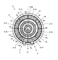
- FIG. 1 is a cross-sectional view showing a hydrogen generator 1 according to the first embodiment.
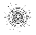
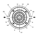
- FIG. 2 is a cross-sectional view showing the hydrogen generator 1 cut by the cooler 19.
- 3 is a cross-sectional view showing the hydrogen generator 1 cut along the line AA ′ in FIG. 1 above CC ′, and cut along the line BB ′ in FIG. 2 below CC ′.
- FIG. For convenience, the upward direction and the downward direction in FIG. 3 will be described as the upward direction and the downward direction of the hydrogen generator 1, respectively.
- the actual hydrogen generator 1 has no directionality and is not limited thereto.
- the hydrogen generator 1 is connected to the fuel cell 11, it may be connected to other hydrogen-using equipment, or the hydrogen generator 1 alone can be used.
- the hydrogen generator 1 mainly includes a reforming catalyst layer (reformer) 6, a burner (combustor) 13, a hydrodesulfurizer 3, and a cooler 19.
- the hydrogen generator 1 may further include the evaporation unit 5, the shift catalyst layer 7, the selective oxidation catalyst layer 9, the inner heat insulating material 15, and the outer heat insulating material 16.
- the hydrogen generator 1 has a hollow cylindrical hydrogen generator 18.
- the hydrogen generator 18 is provided with an evaporator 5, a reforming catalyst layer 6, a shift catalyst layer 7, a selective oxidation catalyst layer 9, and a burner 13.
- a hydrodesulfurizer 3 and a cooler 19 are provided around the hydrogen generator 18 via an inner heat insulating material 15. Further, an outer heat insulating material 16 is provided around the hydrogen generator 18, the hydrodesulfurizer 3 and the cooler 19.
- the hydrogen generator 18 was made into the hollow cylinder shape, it is not limited to this, A square shape may be sufficient.
- the hydrogen generator 18 has an outer wall 18a and a plurality (three in this embodiment) of partition walls 18b, 18c, 18d (18b to 18d).
- the hydrogen generator 18 has a substantially columnar inner space surrounded by a substantially cylindrical outer wall 18a.
- first to third partition walls 18b to 18d having a substantially cylindrical shape are arranged concentrically with respect to the center of the outer wall 18a.
- the internal space is divided into one columnar space and a plurality (three in this embodiment) of cylindrical spaces.
- the first partition wall 18b is disposed at the center of the internal space.
- a cylindrical first space surrounded by the first partition wall 18b is formed.
- the upper end of the first space is closed with a lid, and the lower end is opened.
- a first hole is provided in a part of the lid.
- a burner 13 is inserted into the first space from above through the first hole.
- the second partition wall 18c is disposed outside the first partition wall 18b.
- a cylindrical second space is formed between the second partition wall 18c and the first partition wall 18b.
- the upper end of the second space is opened by the second hole, and the lower end is closed by the first lower surface.
- the second space is connected to the exhaust gas pipe 14 through the second hole. Further, the second space communicates with the first space through a gap between the lower end of the first partition wall 18b and the first lower surface.
- the third partition wall 18d is disposed outside the second partition wall 18c.
- a cylindrical third space is formed between the third partition wall 18d and the second partition wall 18c. The upper end of the third space is opened through the third hole, and the lower end is opened.
- the third space is connected to the downstream source gas supply pipe 2B and the reformed water supply pipe 4 through the third hole.
- the lower space of the third space is filled with a reforming catalyst.
- the reforming catalyst, the third partition wall 18 d and the second partition wall 18 c constitute the reforming catalyst layer 6.
- a wire is arranged so as to wind the second partition wall 18c spirally.
- the wire, the third partition wall 18d, and the second partition wall 18c constitute the evaporation unit 5.
- the outer wall 18a is disposed outside the third partition wall 18d.
- a cylindrical fourth space is formed between the outer wall 18a and the third partition wall 18d. The upper end of the fourth space is opened through the fourth hole, and the lower end is closed by the second lower surface.
- a fifth hole is opened in the outer wall 18a.
- the fourth space communicates with the third space through a gap between the lower end of the third partition wall 18d and the second lower surface.
- the fourth space is connected to the fuel gas supply pipe 10 through the fourth hole. Further, the fourth space is connected to the air supply pipe 8 through the fifth hole.
- the lower space of the fourth space is arranged around the reforming catalyst layer 6, and the upper space of the fourth space is arranged around the evaporation unit 5.
- the lower region in the upper space of the fourth space is filled with the shift catalyst.
- the shift catalyst, the third partition wall 18 d and the outer wall 18 a constitute the shift catalyst layer 7.
- the upper region in the upper space of the fourth space is filled with a selective oxidation catalyst.
- This selective oxidation catalyst, the third partition wall 18d and the outer wall 18a constitute the selective oxidation catalyst layer 9.
- the fifth hole is disposed between the shift catalyst layer 7 and the selective oxidation catalyst layer 9.
- Burner 13 is a combustor that burns combustible gas and heats reforming catalyst layer 6.
- the burner 13 is connected to the fuel cell 11 by an offgas pipe 12, and a combustible gas is supplied through the offgas pipe 12.
- Examples of the combustible gas include raw material gas and fuel gas (off gas) remaining without being consumed by the fuel cell 11.
- the combustor is not limited to a burner as long as the reforming catalyst layer 6 can be heated to an appropriate temperature. Moreover, city gas etc. are used for source gas.
- the reforming catalyst layer 6 is a reformer that generates a fuel gas mainly composed of hydrogen from a raw material gas by a reforming reaction.
- the reforming catalyst layer 6 is heated by the combustion heat of the burner 13 and the combustion gas discharged from the burner 13 so as to reach an appropriate temperature of the reforming catalyst, for example, 650 ° C.
- an appropriate temperature of the reforming catalyst for example, 650 ° C.
- a reforming reaction that is an endothermic reaction occurs in the presence of the reforming catalyst.
- the reforming catalyst layer 6 is formed with a low temperature portion and a high temperature portion having a higher temperature than the low temperature portion.
- the evaporating unit 5 is a device that generates water vapor from water (reformed water) used for the water vapor reforming reaction.
- the evaporation unit 5 is connected to a reforming water supplier (not shown) by the reforming water supply pipe 4.
- the space between the spiral metal rods becomes the reformed water flow path. The reforming water evaporates while flowing through this flow path.
- the shift catalyst layer 7 is a carbon monoxide remover that undergoes a shift reaction with carbon monoxide in the fuel gas under the shift catalyst to remove carbon monoxide from the fuel gas.
- the selective oxidation catalyst layer 9 is a carbon monoxide remover that oxidizes carbon monoxide in the fuel gas with oxygen under the selective oxidation catalyst and removes carbon monoxide from the fuel gas.
- the selective oxidation catalyst layer 9 is disposed on the downstream side of the shift catalyst layer 7.
- An air supply pipe 8 is connected downstream of the shift catalyst layer 7 and upstream of the selective oxidation catalyst layer 9. Air containing oxygen used for oxidation is supplied to the selective oxidation catalyst layer 9 through the air supply pipe 8.
- the hydrodesulfurizer 3 is a reactor that removes sulfur compounds contained in the raw material gas by hydrodesulfurization reaction in the presence of the hydrodesulfurization catalyst 17.
- the hydrodesulfurizer 3 is heated by the reforming catalyst layer 6 so as to reach an appropriate temperature of the hydrodesulfurization catalyst 17, for example, 200 to 300 ° C.
- the hydrodesulfurizer 3 has a flow path (hydrodesulfurization flow path) 21 through which a raw material gas flows.
- the cooler 19 is provided at a position corresponding to the high temperature portion of the reforming catalyst layer 6 and cools the hydrodesulfurizer 3.
- the cooler 19 has a cooling flow path 24 for cooling the hydrodesulfurizer 3.
- air is used as the cooling medium, but a gas other than air or a liquid such as water can be used.
- the cooler 19 is arrange
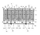
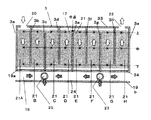
- FIG. 4 is a diagram in which the hydrodesulfurizer 3 is developed by cutting along O-L1 in FIG. 1, and the cooler 19 is developed by cutting along O-L2 in FIG. O is the central axis of the hydrogen generator 1.
- the hydrogen generator 18, the hydrodesulfurizer 3, and the cooler 19 are arranged such that their centers coincide with the central axis O.
- the hydrodesulfurizer 3 has an annular shape and surrounds the outer periphery of the lower portion of the outer wall 18 a via the inner heat insulating material 15.
- the hydrodesulfurizer 3 has a cylindrical first inner cylinder 31 and a first outer cylinder 32.
- the first inner cylinder 31 is concentrically arranged in the first outer cylinder 32, and the annular space between them constitutes a raw material gas flow path (hydrodesulfurization flow path) 21.
- the hydrodesulfurization flow path 21 is filled with a hydrodesulfurization catalyst 17 and an adsorbent.
- the hydrodesulfurization catalyst 17 is a catalyst that promotes a reaction for converting a sulfur component in a raw material gas into hydrogen sulfide, and examples thereof include a catalyst made of copper oxide and zinc oxide.
- the adsorbent for example, a zinc oxide-based adsorbent that adsorbs hydrogen sulfide is used.
- the upper end of the hydrodesulfurization flow path 21 is closed with a first top plate 33 and the lower end is closed with a first bottom plate 34.
- the first top plate 33 is provided with two holes.
- One hole is an inlet (raw material inlet) 20 through which a raw material is supplied, and is connected to a raw material gas supply device (not shown) by an upstream raw material gas supply pipe 2A.
- the other hole is an outlet (raw material outlet) 22 through which the raw material is discharged, and is connected to the downstream raw material gas supply pipe 2B.
- the downstream source gas supply pipe 2B is connected to the reforming water supply pipe 4 and connected to the evaporation section 5 in the first space.
- the hydrodesulfurization flow path 21 is partitioned by a plurality of partition plates.
- the hydrodesulfurization flow path 21 is divided into eight portions (flow path portions) 21A to 21H by eight first to eighth partition plates 3a to 3h.
- the partition plates 3a to 3h are arranged radially from the center O of the hydrodesulfurizer 3 at equal intervals.
- the inner ends of the partition plates 3 a to 3 h are fixed to the first inner cylinder 31, and the outer ends are fixed to the first outer cylinder 32.
- a gap may be provided between the inner ends of the partition plates 3a to 3h and the first inner cylinder 31, or / and between the outer ends and the first outer cylinder 32.
- the eight flow path portions 21H are arranged in the circumferential direction in this order.
- the first flow path portion 21A is a portion where the raw material gas flows from the raw material inlet 20 (FIG. 3) into the hydrodesulfurization flow path 21 as indicated by an arrow a1, and is disposed upstream of the hydrodesulfurization flow path 21.
- the eighth flow passage portion 21H is a portion where the raw material gas flows out from the hydrodesulfurization flow passage 21 to the raw material outlet 22 (FIG.
- the upstream first flow path portion 21A and the downstream eighth flow path portion 21H are adjacent to each other with the first partition plate 3a interposed therebetween.
- the raw material inlet 20 has been arrange
- the raw material outlet 22 has been arrange
- the position of these raw material inlets 20 and the raw material outlets 22 is not limited to this.
- the raw material inlet 20 may be disposed in the eighth flow path portion 21H, and the raw material outlet 22 may be disposed in the first flow path portion 21A.
- the first partition plate 3 a has an upper end fixed to the first top plate 33 and a lower end fixed to the first bottom plate 34. Adjacent first flow path portion 21A and eighth flow path portion 21H are separated by the first partition plate 3a. For this reason, one flow path through which the source gas flows from the first flow path portion 21A to the eighth flow path portion 21H is formed.
- the second to eighth partition plates 3b to 3h other than the first partition plate 3a are alternately fixed to the first top plate 33 or the first bottom plate 34.
- the upper end of the second partition plate 3b is fixed to the first top plate 33, and there is a gap between the lower end and the second bottom plate 19b.
- the lower end of the next third partition plate 3 c is fixed to the first bottom plate 34, and there is a gap between the upper end and the first top plate 33. In this way, gaps are provided alternately. Since the flow passage portions 21A to 21H communicate with each other through this gap, the hydrodesulfurization flow passage 21 meanders in the vertical direction.
- the cooler 19 has an annular shape and surrounds the outer periphery of the lower portion of the outer wall 18 a via the inner heat insulating material 15.
- the cooler 19 has a cylindrical second inner cylinder and a second outer cylinder.
- the second inner cylinder is concentrically arranged in the second outer cylinder, and the annular space between them constitutes a cooling air flow path (cooling flow path) 24.
- the upper end of the cooling channel 24 is closed by the second top plate 19a, and the lower end is closed by the second bottom plate 19b.
- Two holes are provided in the second outer cylinder.
- One hole is an inlet (air inlet) 23 into which cooling air flows, and is connected to an air supplier (not shown).
- the other hole is an outlet (air outlet) 25 through which cooling air flows out, and is open to the atmosphere, for example.
- the second top plate 19 a is also used as the first bottom plate 34 of the hydrodesulfurizer 3.
- the second top plate 19a and the first bottom plate 34 may be provided separately.
- the air supply device may also be used as a supply device for combustion air supplied to the burner 13. Further, the cooling air discharged from the air outlet 25 may be returned to the burner 13. Alternatively, the air supply device may also be used as a supply device for the oxidation air supplied to the selective oxidation catalyst layer 9.
- the air inlet 23 and the air outlet 25 are provided at symmetrical positions in the circumferential direction of the cooling flow path 24. Thereby, the air outlet 25 is arranged at a position farthest from the air inlet 23. Two flow paths are formed in which cooling air flows from the air inlet 23 to the air outlet 25 clockwise and counterclockwise.
- the air inlet 23 and the air outlet 25 are provided between the raw material inlet 20 and the raw material outlet 22 of the hydrodesulfurizer 3.
- the air inlet 23 is closer to the raw material inlet 20 than the raw material outlet 22, and is disposed, for example, between the second flow path portion 21B and the third flow path portion 21C in the circumferential direction.
- the air outlet 25 is closer to the raw material outlet 22 than the raw material inlet 20, and is disposed, for example, between the sixth flow path portion 21F and the seventh flow path portion 21G in the circumferential direction.
- This combustible gas may be a raw material gas supplied from a raw material gas supply device, or may be a combustible gas for the burner 13.
- Burner 13 burns raw material gas with oxygen in the air. Further, high-temperature combustion gas exits from the burner 13 and flows downward in the first space. The combustion gas passes through the gap between the lower end of the first partition wall 18b and the first lower surface, flows upward in the second space, and flows out from the exhaust gas pipe 14.
- the evaporation section 5 and the reforming catalyst layer 6 are heated by the combustion heat of the burner 13 and the high-temperature combustion gas. Then, the shift catalyst layer 7 and the selective oxidation catalyst layer 9 are heated by the high temperature evaporation section 5. Further, the hydrodesulfurizer 3 is heated by the high temperature reforming catalyst layer 6 through the inner heat insulating material 15.
- the reformed water is supplied from the reformed water supply pipe 4 to the evaporation section 5 and is vaporized. Then, the reformed water that has become steam flows into the reforming catalyst layer 6.
- the raw material gas is supplied from the upstream raw material gas supply pipe 2 ⁇ / b> A and flows into the hydrodesulfurizer 3. In the presence of the hydrodesulfurization catalyst at an appropriate temperature, sulfur in the raw material gas reacts and is removed.
- the raw material gas from which sulfur has been removed passes through the downstream raw material gas supply pipe 2 ⁇ / b> B, merges with the water vapor in the evaporator 5, and flows into the reforming catalyst layer 6.
- the raw material gas undergoes a reforming reaction with water vapor to generate fuel gas.
- the fuel gas flows into the shift catalyst layer 7 through the gap between the lower end of the third partition wall 18d and the second lower surface.
- carbon monoxide in the fuel gas is removed by the shift reaction at the shift catalyst layer 7 and flows into the selective oxidation catalyst layer 9.
- air flows from the air supply pipe 8 into the selective oxidation catalyst layer 9.
- carbon monoxide in the remaining fuel gas is oxidized and removed by oxygen in the air.
- the fuel gas from which carbon monoxide has been removed is supplied to the fuel cell 11 via the fuel gas supply pipe 10.
- the fuel gas remaining without being used in the fuel cell 11 is supplied from the off-gas pipe 12 to the burner 13 as combustible gas.
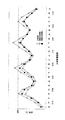
- FIG. 5 is a graph showing the temperature distribution of the hydrodesulfurizer 3.
- the vertical axis represents temperature (° C.), and the horizontal axis represents the position in the hydrodesulfurizer 3.
- This position indicates the position of the x mark in FIG. 5 indicates the temperature in the hydrodesulfurizer of the hydrogen generator not provided with the cooler 19 as a comparative example.
- a circle indicates a temperature in the hydrodesulfurizer 3 of the hydrogen generator 1 according to the first embodiment.
- the flame that generates the combustion heat of the burner 13 extends in the first space in the vertical direction.
- the temperature varies depending on the position of the flame.
- the combustion gas exchanges heat with the reforming catalyst layer 6 while flowing through the first space downward from the burner 13 and flowing upward through the second space. For this reason, the temperature of combustion gas also changes with flow positions.
- the combustion temperature of the burner 13 that heats the reforming catalyst layer 6 and the temperature of the combustion gas are not uniform in the vertical direction. For this reason, the temperature of the heated reforming catalyst layer 6 differs in the vertical direction, and a high temperature portion and a low temperature portion are formed in the reforming catalyst layer 6.
- the extent of the reforming reaction varies depending on the temperature of the reforming catalyst layer 6.
- the reforming catalyst layer 6 has a temperature gradient that becomes higher as it goes downward.
- the temperature is 300 ° C. to 400 ° C. upstream (upper part) of the reforming catalyst layer 6, while the temperature reaches 600 ° C. or more downstream (lower part).
- the temperature becomes higher as it goes downward.
- the temperature is low at a position above the hydrodesulfurizer 3, for example, about 200 ° C.
- the temperature is high at a position below the hydrodesulfurizer 3, for example, 300 ° C. or higher.
- the temperature of the raw material gas also changes in the vertical direction. Specifically, the raw material gas flows from the raw material inlet 20 into the hydrodesulfurization passage 21. The source gas flows downward through the first flow path portion 21A, then flows upward through the second flow path portion 21B, and further flows downward through the third flow path portion 21C. In this way, the flow of the raw material gas flows while alternately changing upward or downward. The source gas then flows out from the source outlet 22.
- a cooler 19 is provided below the hydrodesulfurizer 3.
- the air flowing through the cooling flow path 24 cools the high-temperature hydrodesulfurizer 3. For this reason, the temperature of the hydrodesulfurizer 3 is lower than the temperature indicated by the x mark, as indicated by the ⁇ mark in FIG.
- the cooler 19 is cooled from the bottom of the hydrodesulfurizer 3, the temperature at the lower position in each of the flow path portions 21A to 21H is significantly lower than the upper position. For this reason, it is suppressed that the temperature of the high temperature part of the hydrodesulfurization unit 3 located in the lower part becomes higher than the appropriate temperature of the hydrodesulfurization catalyst 17, and thermal degradation of the hydrodesulfurization catalyst 17 can be prevented. .
- the temperature drop of the high temperature part of the hydrodesulfurizer 3 is larger than that of the low temperature part.
- the entire temperature of the hydrodesulfurization catalyst 17 can be made more uniform while maintaining the temperature of the low temperature portion of the hydrodesulfurizer 3.
- the overall temperature of the hydrodesulfurization catalyst 17 is maintained at 200 ° C. to 300 ° C. More preferably, the entire temperature of the hydrodesulfurization catalyst 17 is 250 ° C. to 300 ° C., and the temperature difference is about 50 ° C. Thereby, the hydrodesulfurization catalyst 17 is maintained at an appropriate temperature.
- the cooler 19 is provided at a position corresponding to the high temperature portion of the reforming catalyst layer 6. Thereby, the cooler 19 can cool the high temperature part of the hydrodesulfurizer 3 heated by this high temperature part. As a result, thermal degradation of the hydrodesulfurization catalyst 17 is prevented, and an increase in the amount of the hydrodesulfurization catalyst 17 mounted in preparation for thermal degradation can be suppressed. Therefore, the increase in the mounting amount can prevent the hydrogen generating apparatus 1 from becoming large, increasing costs, reducing efficiency, and lengthening startup.
- the cooler 19 is cooled from the high temperature portion of the hydrodesulfurizer 3.
- the temperature rise of a high temperature part can be suppressed, suppressing the temperature fall of the low temperature part of the hydrodesulfurizer 3.
- FIG. 1 the entire temperature of the hydrodesulfurization catalyst 17 can be maintained at a substantially uniform temperature close to the upper limit of the appropriate temperature. Therefore, the hydrodesulfurization catalyst 17 can fully function as a whole. For this reason, the loading amount of the hydrodesulfurization catalyst 17 can be suppressed.
- the burner 13 and the combustion gas path are formed so that the high temperature portion of the reforming catalyst layer 6 and the high temperature portion of the hydrodesulfurizer 3 are located below the respective portions 6 and 3. Using the property that heat moves from bottom to top, the heat of the high temperature part can be moved upward in each part 6, 3. As a result, the temperature difference between the reforming catalyst layer 6 and the hydrodesulfurizer 3 can be reduced.
- the hydrodesulfurizer 3 is disposed outside the reforming catalyst layer 6. Thereby, the heat of the reforming catalyst layer 6 can be used for heating the hydrodesulfurization catalyst 17. For this reason, the efficiency and size reduction of the hydrogen generator 1 are achieved.
- Embodiment 2 The hydrogen generator 1 according to Embodiment 2 is different from the hydrogen generator 1 according to Embodiment 1 in the relative positional relationship between the air inlet 23 and the air outlet 25 with respect to the raw material inlet 20 and the raw material outlet 22.
- FIG. 6 is a cross-sectional view of the hydrogen generator 1 according to the second embodiment.
- FIG. 7 is a diagram in which the hydrodesulfurizer 3 is developed by cutting along O-L1 in FIG. 1, and the cooler 19 is developed by cutting along O-L3 in FIG.
- the air inlet 23 is disposed closer to the raw material outlet 22 than the raw material inlet 20.
- the air inlet 23 is disposed between the sixth flow path portion 21F and the seventh flow path portion 21G in the circumferential direction.
- the position of the air inlet 23 is preferably arranged downstream of the middle point of the hydrodesulfurization flow path 21 in the circumferential direction.
- This midpoint is a position that bisects the hydrodesulfurization flow path 21 in the circumferential direction.
- the midpoint corresponds to a position facing the fifth partition plate 3e.
- the position of the air inlet 23 is preferably on the downstream side of the position facing the raw material inlet 20.
- the position facing the raw material inlet 20 is a position farthest from the raw material inlet 20 linearly. In this embodiment, as shown in FIG. 1, it exists in the 5th flow-path part 21E facing the 1st flow-path part 21A connected to the raw material inlet 20 (FIG. 7).
- the position of the air inlet 23 is preferably on the downstream side from the maximum temperature portion of the hydrodesulfurizer 3 or the vicinity thereof.
- the maximum temperature portion of the hydrodesulfurizer 3 is located between the fifth flow path portion 21E and the sixth flow path portion 21F, as shown in FIG.
- the fifth flow path portion 21E and the sixth flow path portion 21F including the highest temperature portion can be cited.
- the position of the air inlet 23 is preferably upstream of the raw material outlet 22 in the circumferential direction. Furthermore, the position of the air inlet 23 may be upstream of the flow path portion adjacent to the first flow path portion 21A where the raw material inlet 20 is located in the circumferential direction (in this embodiment, the eighth flow path portion 21H). preferable.
- the position of the air inlet 23 is preferably in the range of 180 to 360 degrees from the upstream end of the hydrodesulfurization passage 21 with respect to the center of the hydrodesulfurizer 3.
- the position of the air inlet 23 is more preferably in the range of 180 degrees to 315 degrees from the upstream end of the hydrodesulfurization flow path 21.
- the upstream end of the hydrodesulfurization passage 21 is the raw material inlet 20 or the vicinity thereof. In this embodiment, the upstream end corresponds to the first flow path portion 21A side of the first partition plate 3a.
- the air outlet 25 is disposed closer to the raw material inlet 20 than the raw material outlet 22.
- the air outlet 25 is disposed between the second flow path portion 21B and the third flow path portion 21C in the circumferential direction.
- the position of the air outlet 25 is not particularly limited, but is provided to face the air inlet 23.
- the cooler 19 is provided at a position corresponding to the high temperature portion of the reforming catalyst layer 6 as in the first embodiment.
- thermal degradation of the hydrodesulfurization catalyst 17 can be prevented, and the entire temperature of the hydrodesulfurization catalyst 17 can be maintained at a substantially uniform temperature close to the upper limit of the appropriate temperature.
- the burner 13 and the combustion gas path are formed so that the high temperature portion of the reforming catalyst layer 6 and the high temperature portion of the hydrodesulfurizer 3 are located below the respective portions 6 and 3. Thereby, the temperature difference in the reforming catalyst layer 6 and the hydrodesulfurizer 3 can be reduced.
- the hydrodesulfurizer 3 is disposed outside the reforming catalyst layer 6. Thereby, the heat of the reforming catalyst layer 6 can be used for heating the hydrodesulfurization catalyst 17.
- the raw material gas flows through the hydrodesulfurization passage 21 in the circumferential direction from the raw material inlet 20 to the raw material outlet 22 while being heated by the reforming catalyst layer 6. For this reason, the temperature of the raw material gas rises toward the downstream side of the hydrodesulfurization flow path 21, and accordingly, the temperature of the hydrodesulfurization catalyst 17 at the raw material outlet 22 is higher than that of the raw material inlet 20.
- the air inlet 23 is arranged closer to the raw material outlet 22 than the raw material inlet 20.
- the cooling air can flow from the air inlet 23 and cool the high-temperature hydrodesulfurization catalyst 17 in the vicinity of the raw material outlet 22.
- This cooling air is before the temperature of the hydrodesulfurization catalyst 17 near the air inlet 23 is cooled and raised. For this reason, the temperature of the cooling air is low, and the high-temperature hydrodesulfurization catalyst 17 can be cooled to an appropriate temperature. Therefore, thermal degradation of the hydrodesulfurization catalyst 17 can be prevented more reliably.
- the air inlet 23 is disposed downstream from the midpoint of the hydrodesulfurization flow path 21 in the circumferential direction. Thereby, the low-temperature cooling air that has flowed in from the air inlet 23 can be cooled to an appropriate temperature on the downstream side of the middle point of the hydrodesulfurization flow path 21 that is likely to become high temperature. Thereby, thermal degradation of the hydrodesulfurization catalyst 17 can be prevented.
- the air inlet 23 is arranged on the downstream side from the position facing the raw material inlet 20.
- the temperature at the position facing the raw material inlet 20 tends to be the highest.
- the low-temperature cooling air that has flowed from the air inlet 23 can be cooled to an appropriate temperature at the position of the hydrodesulfurization flow path 21 that tends to become high temperature. Thereby, thermal degradation of the hydrodesulfurization catalyst 17 can be prevented.
- the air inlet 23 is disposed downstream from the maximum temperature portion of the hydrodesulfurizer 3 or the vicinity thereof. On the downstream side of the maximum temperature portion of the hydrodesulfurizer 3 or the vicinity thereof, the low-temperature cooling air flowing from the air inlet 23 can be cooled to an appropriate temperature. Thereby, thermal degradation of the hydrodesulfurization catalyst 17 can be prevented.
- the air inlet 23 is arranged on the upstream side of the channel portion adjacent to the first channel portion 21A where the material inlet 20 is located in the circumferential direction.
- the eighth flow path portion 21H where the raw material outlet 22 is located is normally located downstream of the hydrodesulfurization flow path 21, and therefore has the highest temperature.
- the eighth flow path portion 21H is adjacent to the first flow path portion 21A where the raw material inlet 20 is at the lowest temperature. For this reason, the temperature of the eighth flow path portion 21H is lowered by heat exchange with the first flow path portion 21A. Therefore, the temperatures of the fifth to seventh flow path portions 21E to 21G on the upstream side of the eighth flow path portion 21H are increased.
- the low-temperature cooling air that has flowed in from the air inlet 23 can cool the high-temperature flow channel portion upstream of the eighth flow channel portion 21H adjacent to the first flow channel portion 21A to an appropriate temperature. Thereby, thermal degradation of the hydrodesulfurization catalyst 17 can be prevented.
- the air inlet 23 is arranged close to the raw material outlet 22 and the air outlet 25 is arranged close to the raw material inlet 20.
- the low-temperature cooling air flowing in from the air inlet 23 first cools the hydrodesulfurization catalyst 17 in the high-temperature fifth to eighth flow path portions 21E to 21H near the raw material outlet 22.
- the cooling air that has cooled and raised the temperature of these high temperature portions cools the hydrodesulfurization catalyst 17 in the first to fourth flow path portions 21A to 21D in the vicinity of the low temperature raw material inlet 20. Accordingly, as shown in FIG.
- the temperature of the hydrodesulfurization catalyst 17 according to the second embodiment is the same as that of the hydrodesulfurization catalyst according to the first embodiment. The temperature is lower than 17.
- the temperature of the hydrodesulfurization catalyst 17 according to the second embodiment is higher than the temperature of the hydrodesulfurization catalyst 17 according to the first embodiment. .
- the entire temperature of the hydrodesulfurization catalyst 17 can be made high and uniform within the appropriate temperature range. As a result, the hydrodesulfurization catalyst 17 can function efficiently.
- the hydrodesulfurization flow path 21 is partitioned by the eight first to eighth partition plates 3a to 3h.
- the number of partition plates is not limited to eight.
- the hydrodesulfurization flow path 21 may be partitioned only by the first partition plate 3 a between the raw material inlet 20 and the raw material outlet 22. Further, the hydrodesulfurization flow path 21 may be divided into one flow path without partitioning.
- the hydrogen generator of the present invention is useful as a hydrogen generator that reduces the amount of hydrodesulfurization catalyst mounted while maintaining miniaturization and high efficiency.
Landscapes
- Chemical & Material Sciences (AREA)
- Chemical Kinetics & Catalysis (AREA)
- Organic Chemistry (AREA)
- Engineering & Computer Science (AREA)
- Life Sciences & Earth Sciences (AREA)
- Combustion & Propulsion (AREA)
- Inorganic Chemistry (AREA)
- General Health & Medical Sciences (AREA)
- Health & Medical Sciences (AREA)
- Manufacturing & Machinery (AREA)
- Sustainable Development (AREA)
- Sustainable Energy (AREA)
- Electrochemistry (AREA)
- General Chemical & Material Sciences (AREA)
- Fuel Cell (AREA)
- Hydrogen, Water And Hydrids (AREA)
Abstract
Description
本発明者らは、水素生成装置の小型化および高効率化を維持しながら、水添脱硫触媒の搭載量の低減化を図るために鋭意検討をした。この結果、本発明者らは従来技術には下記のような問題があることを見出した。
第1の本発明に係る水素生成装置は、原料ガスから水素を主成分とする燃料ガスを生成する改質器と、前記改質器を加熱する燃焼器と、前記改質器により加熱されて、前記原料ガス中に含まれる硫黄化合物を水添脱硫反応により除去する水添脱硫器と、前記水添脱硫器を冷却する冷却器と、を備え、前記改質器は、低温部、および、前記低温部より温度が高い高温部を含み、前記冷却器は、前記改質器の高温部に対応する位置に設けられている。
<水素生成装置の構成>
図1は、実施の形態1に係る水素生成装置1を示す断面図である。図2は、冷却器19で切断した水素生成装置1を示す断面図である。図3は、C-C’より上は図1のA-A’に沿って切断し、C-C’より下は図2のB-B’に沿って切断した水素生成装置1を示す断面図である。なお、便宜上、図3における上方向および下方向をそれぞれ水素生成装置1の上方向および下方向として説明する。但し、実際の水素生成装置1に方向性はなく、これに限定されるものではない。また、水素生成装置1は、燃料電池11に接続されているが、他の水素利用機器に接続されていてもよいし、また、水素生成装置1単独でも使用することができる。
図4は、図1のO-L1に沿って切断して水添脱硫器3を展開し、図2のO-L2に沿って切断して冷却器19の展開した図である。なお、Oは、水素生成装置1の中心軸である。水素生成装置1において、水素生成器18、水添脱硫器3および冷却器19は、各中心が中心軸Oに一致するように配置されている。
図3に示すように、冷却器19は、環形状であって、内断熱材15を介して外壁18aの下部の外周を取り囲んでいる。冷却器19は、円筒形状の第2内筒および第2外筒を有している。第2外筒内に第2内筒が同心円状に配置されており、これらの間の環状空間が冷却用の空気の流路(冷却流路)24を構成している。
図3に示すように、水素生成装置1が動作すると、可燃性ガスおよび空気がバーナ13に供給される。この可燃性ガスは、原料ガス供給器から供給される原料ガスであってもよいし、バーナ13用の可燃性ガスであってもよい。
図5は、水添脱硫器3の温度分布を示すグラフである。縦軸が温度(℃)を示し、横軸が水添脱硫器3における位置を示している。この位置は、図4の×印の位置を示している。図5の×印は、比較例として、冷却器19が設けられていない水素生成装置の水添脱硫器における温度を示す。○印は、実施の形態1に係る水素生成装置1の水添脱硫器3における温度を示す。
冷却器19は、改質触媒層6の高温部に対応する位置に設けられている。これにより、この高温部により加熱された水添脱硫器3の高温部を冷却器19は冷却することができる。この結果、水添脱硫触媒17の熱劣化が防止され、熱劣化に備えた水添脱硫触媒17の搭載量の増加を抑制することができる。したがって、この搭載量の増加によって水素生成装置1の大型化、コスト上昇、効率の低下、および、起動の長時間化を防止することができる。
実施の形態2に係る水素生成装置1では、実施の形態1に係る水素生成装置1と、原料入口20および原料出口22に関する空気入口23および空気出口25の相対的な位置関係が異なる。
上記全実施の形態では、8枚の第1~第8仕切り板3a~3hにより、水添脱硫流路21を仕切った。ただし、仕切り板の数は8枚に限定されない。たとえば、原料入口20と原料出口22との間の第1仕切り板3aのみで水添脱硫流路21を仕切ってもよい。また、水添脱硫流路21を仕切らず、1つの流路としてもよい。
3 水添脱硫器
6 改質触媒層(改質器)
13 バーナ(燃焼器)
19 冷却器
21 水添脱硫流路
24 冷却流路
23 空気入口(冷却流路の入口)
25 空気出口
Claims (2)
- 原料ガスから水素を主成分とする燃料ガスを生成する改質器と、
前記改質器を加熱する燃焼器と、
前記改質器により加熱されて、前記原料ガス中に含まれる硫黄化合物を水添脱硫反応により除去する水添脱硫器と、
前記水添脱硫器を冷却する冷却器と、を備え、
前記改質器は、低温部、および、前記低温部より温度が高い高温部を含み、
前記冷却器は、前記改質器の高温部に対応する位置に設けられている、水素生成装置。 - 前記水添脱硫器は、前記原料ガスを流す水添脱硫流路をその内部に有し、
前記冷却器は、冷却流路を有し、
前記冷却流路の入口は、前記水添脱硫流路の中点よりも下流に設けられている、請求項1記載の水素生成装置。
Priority Applications (3)
| Application Number | Priority Date | Filing Date | Title |
|---|---|---|---|
| US14/647,447 US20150303502A1 (en) | 2012-12-17 | 2013-12-16 | Hydrogen generator |
| EP13865205.2A EP2933226A4 (en) | 2012-12-17 | 2013-12-16 | HYDROGEN PRODUCTION DEVICE |
| JP2014552928A JP5895169B2 (ja) | 2012-12-17 | 2013-12-16 | 水素生成装置 |
Applications Claiming Priority (2)
| Application Number | Priority Date | Filing Date | Title |
|---|---|---|---|
| JP2012-274287 | 2012-12-17 | ||
| JP2012274287 | 2012-12-17 |
Publications (1)
| Publication Number | Publication Date |
|---|---|
| WO2014097601A1 true WO2014097601A1 (ja) | 2014-06-26 |
Family
ID=50977963
Family Applications (1)
| Application Number | Title | Priority Date | Filing Date |
|---|---|---|---|
| PCT/JP2013/007375 Ceased WO2014097601A1 (ja) | 2012-12-17 | 2013-12-16 | 水素生成装置 |
Country Status (4)
| Country | Link |
|---|---|
| US (1) | US20150303502A1 (ja) |
| EP (1) | EP2933226A4 (ja) |
| JP (1) | JP5895169B2 (ja) |
| WO (1) | WO2014097601A1 (ja) |
Cited By (1)
| Publication number | Priority date | Publication date | Assignee | Title |
|---|---|---|---|---|
| JP2023103838A (ja) * | 2022-01-14 | 2023-07-27 | 株式会社デンソー | 燃料電池装置 |
Families Citing this family (3)
| Publication number | Priority date | Publication date | Assignee | Title |
|---|---|---|---|---|
| AT519860B1 (de) * | 2017-04-13 | 2020-11-15 | Avl List Gmbh | Brennstoffzellensystem mit ringförmigem Reformer |
| US10369540B2 (en) | 2017-04-17 | 2019-08-06 | Honeywell International Inc. | Cell structures for use in heat exchangers, and methods of producing the same |
| US10128518B2 (en) | 2017-04-17 | 2018-11-13 | Honeywell International Inc. | Hydrogen production system and methods of producing the same |
Citations (11)
| Publication number | Priority date | Publication date | Assignee | Title |
|---|---|---|---|---|
| JPH10214632A (ja) | 1997-01-31 | 1998-08-11 | Toshiba Corp | 燃料電池発電装置 |
| JP2005255896A (ja) * | 2004-03-12 | 2005-09-22 | Nippon Oil Corp | 脱硫器、脱硫システム、水素製造装置および燃料電池システム |
| JP2007273142A (ja) * | 2006-03-30 | 2007-10-18 | Kyocera Corp | 脱硫装置およびその使用方法 |
| JP2010058995A (ja) | 2008-09-01 | 2010-03-18 | Tokyo Gas Co Ltd | 水添脱硫器一体型円筒式水蒸気改質器 |
| JP2010067353A (ja) * | 2008-09-08 | 2010-03-25 | Honda Motor Co Ltd | 脱硫装置 |
| JP2011207704A (ja) * | 2010-03-30 | 2011-10-20 | Jx Nippon Oil & Energy Corp | 水素製造装置及び燃料電池システム |
| JP2012020898A (ja) * | 2010-07-14 | 2012-02-02 | Panasonic Corp | 水素生成装置及びそれを備える燃料電池システム |
| JP2012041238A (ja) | 2010-08-20 | 2012-03-01 | Panasonic Corp | 水素生成装置及び燃料電池システム |
| WO2013061580A1 (ja) * | 2011-10-24 | 2013-05-02 | パナソニック株式会社 | 水添脱硫装置、水素生成装置及び燃料電池システム |
| WO2013150798A1 (ja) * | 2012-04-05 | 2013-10-10 | パナソニック株式会社 | 水素生成装置 |
| JP2013216543A (ja) * | 2012-04-10 | 2013-10-24 | Panasonic Corp | 水素生成装置 |
Family Cites Families (16)
| Publication number | Priority date | Publication date | Assignee | Title |
|---|---|---|---|---|
| US4909808A (en) * | 1987-10-14 | 1990-03-20 | The United States Of America As Represented By The Administrator Of The National Aeronautics And Space Administration | Steam reformer with catalytic combustor |
| US6126908A (en) * | 1996-08-26 | 2000-10-03 | Arthur D. Little, Inc. | Method and apparatus for converting hydrocarbon fuel into hydrogen gas and carbon dioxide |
| JP2000034103A (ja) * | 1998-07-21 | 2000-02-02 | Matsushita Electric Works Ltd | 燃料改質装置 |
| EP1094031A4 (en) * | 1999-04-20 | 2005-02-02 | Tokyo Gas Co Ltd | CYLINDRICAL ONE-TUBE REFORMER AND METHOD OF USE THEREOF |
| CA2357960C (en) * | 2000-10-10 | 2007-01-30 | Tokyo Gas Co., Ltd. | Single-pipe cylinder type reformer |
| US7182921B2 (en) * | 2001-06-04 | 2007-02-27 | Tokyo Gas Co., Ltd. | Cylindrical steam reforming unit |
| US6936238B2 (en) * | 2002-09-06 | 2005-08-30 | General Motors Corporation | Compact partial oxidation/steam reactor with integrated air preheater, fuel and water vaporizer |
| US6932958B2 (en) * | 2003-03-26 | 2005-08-23 | Gas Technology Institute | Simplified three-stage fuel processor |
| US7332003B1 (en) * | 2003-09-04 | 2008-02-19 | Aspen Products Group, Inc. | Hydrocarbon fuel processing for hydrogen generation |
| KR101127688B1 (ko) * | 2004-12-07 | 2012-03-23 | 에스케이이노베이션 주식회사 | 원통형 소형 개질 장치 |
| US8273489B2 (en) * | 2006-06-12 | 2012-09-25 | Fuji Electric Co., Ltd. | Hydrogen generator and fuel cell system including the same |
| KR101328983B1 (ko) * | 2006-10-13 | 2013-11-13 | 삼성에스디아이 주식회사 | 수소생성장치 및 그 구동 방법 |
| KR101328984B1 (ko) * | 2006-10-24 | 2013-11-13 | 삼성에스디아이 주식회사 | 연료전지 시스템의 개질기 및 이의 제어 방법 |
| US9079771B2 (en) * | 2007-07-18 | 2015-07-14 | Panasonic Corporation | Hydrogen generation system, fuel cell system, and method for operation of hydrogen generation system |
| KR100981109B1 (ko) * | 2008-10-27 | 2010-09-08 | 한국과학기술원 | 고체산화물 연료전지의 연료 개질을 위한 통합반응기 |
| JP5681211B2 (ja) * | 2011-06-08 | 2015-03-04 | パナソニックIpマネジメント株式会社 | 水素発生装置、これを備える燃料電池システム、及び水素発生装置の運転方法 |
-
2013
- 2013-12-16 WO PCT/JP2013/007375 patent/WO2014097601A1/ja not_active Ceased
- 2013-12-16 US US14/647,447 patent/US20150303502A1/en not_active Abandoned
- 2013-12-16 EP EP13865205.2A patent/EP2933226A4/en not_active Withdrawn
- 2013-12-16 JP JP2014552928A patent/JP5895169B2/ja not_active Expired - Fee Related
Patent Citations (11)
| Publication number | Priority date | Publication date | Assignee | Title |
|---|---|---|---|---|
| JPH10214632A (ja) | 1997-01-31 | 1998-08-11 | Toshiba Corp | 燃料電池発電装置 |
| JP2005255896A (ja) * | 2004-03-12 | 2005-09-22 | Nippon Oil Corp | 脱硫器、脱硫システム、水素製造装置および燃料電池システム |
| JP2007273142A (ja) * | 2006-03-30 | 2007-10-18 | Kyocera Corp | 脱硫装置およびその使用方法 |
| JP2010058995A (ja) | 2008-09-01 | 2010-03-18 | Tokyo Gas Co Ltd | 水添脱硫器一体型円筒式水蒸気改質器 |
| JP2010067353A (ja) * | 2008-09-08 | 2010-03-25 | Honda Motor Co Ltd | 脱硫装置 |
| JP2011207704A (ja) * | 2010-03-30 | 2011-10-20 | Jx Nippon Oil & Energy Corp | 水素製造装置及び燃料電池システム |
| JP2012020898A (ja) * | 2010-07-14 | 2012-02-02 | Panasonic Corp | 水素生成装置及びそれを備える燃料電池システム |
| JP2012041238A (ja) | 2010-08-20 | 2012-03-01 | Panasonic Corp | 水素生成装置及び燃料電池システム |
| WO2013061580A1 (ja) * | 2011-10-24 | 2013-05-02 | パナソニック株式会社 | 水添脱硫装置、水素生成装置及び燃料電池システム |
| WO2013150798A1 (ja) * | 2012-04-05 | 2013-10-10 | パナソニック株式会社 | 水素生成装置 |
| JP2013216543A (ja) * | 2012-04-10 | 2013-10-24 | Panasonic Corp | 水素生成装置 |
Non-Patent Citations (1)
| Title |
|---|
| See also references of EP2933226A4 |
Cited By (2)
| Publication number | Priority date | Publication date | Assignee | Title |
|---|---|---|---|---|
| JP2023103838A (ja) * | 2022-01-14 | 2023-07-27 | 株式会社デンソー | 燃料電池装置 |
| JP7753893B2 (ja) | 2022-01-14 | 2025-10-15 | 株式会社デンソー | 燃料電池装置 |
Also Published As
| Publication number | Publication date |
|---|---|
| EP2933226A1 (en) | 2015-10-21 |
| US20150303502A1 (en) | 2015-10-22 |
| JP5895169B2 (ja) | 2016-03-30 |
| JPWO2014097601A1 (ja) | 2017-01-12 |
| EP2933226A4 (en) | 2016-06-15 |
Similar Documents
| Publication | Publication Date | Title |
|---|---|---|
| JP5870320B2 (ja) | 燃料電池システム | |
| CN101500940B (zh) | 氢生成装置以及燃料电池系统 | |
| US20020085970A1 (en) | Shell and tube reactor | |
| JP5476392B2 (ja) | 燃料電池システム | |
| JP5895169B2 (ja) | 水素生成装置 | |
| JP5468713B1 (ja) | 水素生成装置および燃料電池システム | |
| JP5600460B2 (ja) | 水素製造装置及び燃料電池システム | |
| JP6405211B2 (ja) | 燃料電池システム | |
| JP5477748B2 (ja) | 水素発生装置及び燃料電池発電装置 | |
| JP5807167B2 (ja) | 水素生成装置 | |
| JP5163147B2 (ja) | 熱交換器及び複合型燃料反応器 | |
| JP5948605B2 (ja) | 水素生成装置 | |
| JP6518086B2 (ja) | 燃料電池システム | |
| JP2012041238A (ja) | 水素生成装置及び燃料電池システム | |
| JP5618451B2 (ja) | 燃料電池発電システムの液体燃料処理装置 | |
| JP2022121769A (ja) | 水素生成装置 | |
| JP5938580B2 (ja) | 水素生成装置 | |
| JP5538025B2 (ja) | 水素製造装置及び燃料電池システム | |
| JP2017001922A (ja) | 水素発生装置と水素発生方法 | |
| US9614241B2 (en) | Hydrogen-purification apparatus and fuel-cell system using same | |
| JP2014189410A (ja) | 水素生成装置 | |
| JP2016160141A (ja) | 水素生成装置およびそれを備えた燃料電池システム | |
| JP2011136867A (ja) | 改質装置、改質ユニット、および、燃料電池システム | |
| JP2017039626A (ja) | 水素生成装置 | |
| JP2016181369A (ja) | 燃料電池システム |
Legal Events
| Date | Code | Title | Description |
|---|---|---|---|
| 121 | Ep: the epo has been informed by wipo that ep was designated in this application |
Ref document number: 13865205 Country of ref document: EP Kind code of ref document: A1 |
|
| DPE1 | Request for preliminary examination filed after expiration of 19th month from priority date (pct application filed from 20040101) | ||
| ENP | Entry into the national phase |
Ref document number: 2014552928 Country of ref document: JP Kind code of ref document: A |
|
| WWE | Wipo information: entry into national phase |
Ref document number: 14647447 Country of ref document: US |
|
| NENP | Non-entry into the national phase |
Ref country code: DE |
|
| WWE | Wipo information: entry into national phase |
Ref document number: 2013865205 Country of ref document: EP |