WO2014097702A1 - 画像処理装置、電子機器、内視鏡装置、プログラム及び画像処理方法 - Google Patents
画像処理装置、電子機器、内視鏡装置、プログラム及び画像処理方法 Download PDFInfo
- Publication number
- WO2014097702A1 WO2014097702A1 PCT/JP2013/075870 JP2013075870W WO2014097702A1 WO 2014097702 A1 WO2014097702 A1 WO 2014097702A1 JP 2013075870 W JP2013075870 W JP 2013075870W WO 2014097702 A1 WO2014097702 A1 WO 2014097702A1
- Authority
- WO
- WIPO (PCT)
- Prior art keywords
- information
- unit
- subject
- distance
- image
- Prior art date
- Legal status (The legal status is an assumption and is not a legal conclusion. Google has not performed a legal analysis and makes no representation as to the accuracy of the status listed.)
- Ceased
Links
Images








Classifications
-
- A—HUMAN NECESSITIES
- A61—MEDICAL OR VETERINARY SCIENCE; HYGIENE
- A61B—DIAGNOSIS; SURGERY; IDENTIFICATION
- A61B1/00—Instruments for performing medical examinations of the interior of cavities or tubes of the body by visual or photographical inspection, e.g. endoscopes; Illuminating arrangements therefor
- A61B1/06—Instruments for performing medical examinations of the interior of cavities or tubes of the body by visual or photographical inspection, e.g. endoscopes; Illuminating arrangements therefor with illuminating arrangements
- A61B1/0661—Endoscope light sources
- A61B1/0684—Endoscope light sources using light emitting diodes [LED]
-
- G—PHYSICS
- G06—COMPUTING OR CALCULATING; COUNTING
- G06T—IMAGE DATA PROCESSING OR GENERATION, IN GENERAL
- G06T7/00—Image analysis
- G06T7/0002—Inspection of images, e.g. flaw detection
- G06T7/0012—Biomedical image inspection
-
- A—HUMAN NECESSITIES
- A61—MEDICAL OR VETERINARY SCIENCE; HYGIENE
- A61B—DIAGNOSIS; SURGERY; IDENTIFICATION
- A61B1/00—Instruments for performing medical examinations of the interior of cavities or tubes of the body by visual or photographical inspection, e.g. endoscopes; Illuminating arrangements therefor
- A61B1/00002—Operational features of endoscopes
- A61B1/00004—Operational features of endoscopes characterised by electronic signal processing
- A61B1/00009—Operational features of endoscopes characterised by electronic signal processing of image signals during a use of endoscope
-
- A—HUMAN NECESSITIES
- A61—MEDICAL OR VETERINARY SCIENCE; HYGIENE
- A61B—DIAGNOSIS; SURGERY; IDENTIFICATION
- A61B1/00—Instruments for performing medical examinations of the interior of cavities or tubes of the body by visual or photographical inspection, e.g. endoscopes; Illuminating arrangements therefor
- A61B1/00002—Operational features of endoscopes
- A61B1/00004—Operational features of endoscopes characterised by electronic signal processing
- A61B1/00009—Operational features of endoscopes characterised by electronic signal processing of image signals during a use of endoscope
- A61B1/000094—Operational features of endoscopes characterised by electronic signal processing of image signals during a use of endoscope extracting biological structures
-
- A—HUMAN NECESSITIES
- A61—MEDICAL OR VETERINARY SCIENCE; HYGIENE
- A61B—DIAGNOSIS; SURGERY; IDENTIFICATION
- A61B1/00—Instruments for performing medical examinations of the interior of cavities or tubes of the body by visual or photographical inspection, e.g. endoscopes; Illuminating arrangements therefor
- A61B1/04—Instruments for performing medical examinations of the interior of cavities or tubes of the body by visual or photographical inspection, e.g. endoscopes; Illuminating arrangements therefor combined with photographic or television appliances
- A61B1/046—Instruments for performing medical examinations of the interior of cavities or tubes of the body by visual or photographical inspection, e.g. endoscopes; Illuminating arrangements therefor combined with photographic or television appliances for infrared imaging
-
- A—HUMAN NECESSITIES
- A61—MEDICAL OR VETERINARY SCIENCE; HYGIENE
- A61B—DIAGNOSIS; SURGERY; IDENTIFICATION
- A61B1/00—Instruments for performing medical examinations of the interior of cavities or tubes of the body by visual or photographical inspection, e.g. endoscopes; Illuminating arrangements therefor
- A61B1/06—Instruments for performing medical examinations of the interior of cavities or tubes of the body by visual or photographical inspection, e.g. endoscopes; Illuminating arrangements therefor with illuminating arrangements
- A61B1/0638—Instruments for performing medical examinations of the interior of cavities or tubes of the body by visual or photographical inspection, e.g. endoscopes; Illuminating arrangements therefor with illuminating arrangements providing two or more wavelengths
-
- A—HUMAN NECESSITIES
- A61—MEDICAL OR VETERINARY SCIENCE; HYGIENE
- A61B—DIAGNOSIS; SURGERY; IDENTIFICATION
- A61B5/00—Measuring for diagnostic purposes; Identification of persons
- A61B5/0059—Measuring for diagnostic purposes; Identification of persons using light, e.g. diagnosis by transillumination, diascopy, fluorescence
- A61B5/0082—Measuring for diagnostic purposes; Identification of persons using light, e.g. diagnosis by transillumination, diascopy, fluorescence adapted for particular medical purposes
- A61B5/0084—Measuring for diagnostic purposes; Identification of persons using light, e.g. diagnosis by transillumination, diascopy, fluorescence adapted for particular medical purposes for introduction into the body, e.g. by catheters
- A61B5/0086—Measuring for diagnostic purposes; Identification of persons using light, e.g. diagnosis by transillumination, diascopy, fluorescence adapted for particular medical purposes for introduction into the body, e.g. by catheters using infrared radiation
-
- A—HUMAN NECESSITIES
- A61—MEDICAL OR VETERINARY SCIENCE; HYGIENE
- A61B—DIAGNOSIS; SURGERY; IDENTIFICATION
- A61B5/00—Measuring for diagnostic purposes; Identification of persons
- A61B5/103—Measuring devices for testing the shape, pattern, colour, size or movement of the body or parts thereof, for diagnostic purposes
- A61B5/107—Measuring physical dimensions, e.g. size of the entire body or parts thereof
- A61B5/1077—Measuring of profiles
-
- A—HUMAN NECESSITIES
- A61—MEDICAL OR VETERINARY SCIENCE; HYGIENE
- A61B—DIAGNOSIS; SURGERY; IDENTIFICATION
- A61B5/00—Measuring for diagnostic purposes; Identification of persons
- A61B5/103—Measuring devices for testing the shape, pattern, colour, size or movement of the body or parts thereof, for diagnostic purposes
- A61B5/107—Measuring physical dimensions, e.g. size of the entire body or parts thereof
- A61B5/1079—Measuring physical dimensions, e.g. size of the entire body or parts thereof using optical or photographic means
-
- G—PHYSICS
- G01—MEASURING; TESTING
- G01B—MEASURING LENGTH, THICKNESS OR SIMILAR LINEAR DIMENSIONS; MEASURING ANGLES; MEASURING AREAS; MEASURING IRREGULARITIES OF SURFACES OR CONTOURS
- G01B11/00—Measuring arrangements characterised by the use of optical techniques
- G01B11/14—Measuring arrangements characterised by the use of optical techniques for measuring distance or clearance between spaced objects or spaced apertures
-
- G—PHYSICS
- G01—MEASURING; TESTING
- G01B—MEASURING LENGTH, THICKNESS OR SIMILAR LINEAR DIMENSIONS; MEASURING ANGLES; MEASURING AREAS; MEASURING IRREGULARITIES OF SURFACES OR CONTOURS
- G01B11/00—Measuring arrangements characterised by the use of optical techniques
- G01B11/24—Measuring arrangements characterised by the use of optical techniques for measuring contours or curvatures
-
- G—PHYSICS
- G02—OPTICS
- G02B—OPTICAL ELEMENTS, SYSTEMS OR APPARATUS
- G02B23/00—Telescopes, e.g. binoculars; Periscopes; Instruments for viewing the inside of hollow bodies; Viewfinders; Optical aiming or sighting devices
- G02B23/24—Instruments or systems for viewing the inside of hollow bodies, e.g. fibrescopes
- G02B23/2407—Optical details
- G02B23/2415—Stereoscopic endoscopes
-
- G—PHYSICS
- G06—COMPUTING OR CALCULATING; COUNTING
- G06F—ELECTRIC DIGITAL DATA PROCESSING
- G06F18/00—Pattern recognition
- G06F18/20—Analysing
- G06F18/24—Classification techniques
-
- G—PHYSICS
- G06—COMPUTING OR CALCULATING; COUNTING
- G06T—IMAGE DATA PROCESSING OR GENERATION, IN GENERAL
- G06T7/00—Image analysis
- G06T7/60—Analysis of geometric attributes
- G06T7/64—Analysis of geometric attributes of convexity or concavity
-
- H—ELECTRICITY
- H04—ELECTRIC COMMUNICATION TECHNIQUE
- H04N—PICTORIAL COMMUNICATION, e.g. TELEVISION
- H04N23/00—Cameras or camera modules comprising electronic image sensors; Control thereof
- H04N23/50—Constructional details
- H04N23/555—Constructional details for picking-up images in sites, inaccessible due to their dimensions or hazardous conditions, e.g. endoscopes or borescopes
-
- H—ELECTRICITY
- H04—ELECTRIC COMMUNICATION TECHNIQUE
- H04N—PICTORIAL COMMUNICATION, e.g. TELEVISION
- H04N23/00—Cameras or camera modules comprising electronic image sensors; Control thereof
- H04N23/56—Cameras or camera modules comprising electronic image sensors; Control thereof provided with illuminating means
-
- H—ELECTRICITY
- H04—ELECTRIC COMMUNICATION TECHNIQUE
- H04N—PICTORIAL COMMUNICATION, e.g. TELEVISION
- H04N23/00—Cameras or camera modules comprising electronic image sensors; Control thereof
- H04N23/70—Circuitry for compensating brightness variation in the scene
- H04N23/74—Circuitry for compensating brightness variation in the scene by influencing the scene brightness using illuminating means
-
- A—HUMAN NECESSITIES
- A61—MEDICAL OR VETERINARY SCIENCE; HYGIENE
- A61B—DIAGNOSIS; SURGERY; IDENTIFICATION
- A61B1/00—Instruments for performing medical examinations of the interior of cavities or tubes of the body by visual or photographical inspection, e.g. endoscopes; Illuminating arrangements therefor
- A61B1/31—Instruments for performing medical examinations of the interior of cavities or tubes of the body by visual or photographical inspection, e.g. endoscopes; Illuminating arrangements therefor for the rectum, e.g. proctoscopes, sigmoidoscopes, colonoscopes
-
- G—PHYSICS
- G06—COMPUTING OR CALCULATING; COUNTING
- G06T—IMAGE DATA PROCESSING OR GENERATION, IN GENERAL
- G06T2207/00—Indexing scheme for image analysis or image enhancement
- G06T2207/10—Image acquisition modality
- G06T2207/10068—Endoscopic image
-
- G—PHYSICS
- G06—COMPUTING OR CALCULATING; COUNTING
- G06T—IMAGE DATA PROCESSING OR GENERATION, IN GENERAL
- G06T2207/00—Indexing scheme for image analysis or image enhancement
- G06T2207/30—Subject of image; Context of image processing
- G06T2207/30004—Biomedical image processing
- G06T2207/30028—Colon; Small intestine
-
- G—PHYSICS
- G06—COMPUTING OR CALCULATING; COUNTING
- G06T—IMAGE DATA PROCESSING OR GENERATION, IN GENERAL
- G06T2207/00—Indexing scheme for image analysis or image enhancement
- G06T2207/30—Subject of image; Context of image processing
- G06T2207/30004—Biomedical image processing
- G06T2207/30092—Stomach; Gastric
Definitions
- the present invention relates to an image processing device, an electronic device, an endoscope device, a program, an image processing method, and the like.
- a process for enhancing the structure of a captured image for example, an uneven structure such as a groove
- a process for enhancing a specific spatial frequency has been widely used. Is not suitable.
- a method of capturing an image of a changed subject by causing some change on the subject side instead of detecting the uneven state by image processing.
- a pigment such as indigo carmine.
- it is troublesome and costly to disperse the dye and the original color of the subject may be damaged by the dispersed dye, and the visibility of structures other than the unevenness may be reduced.
- the pigment is applied to the living body, there may be a problem that the patient is highly invasive.
- Patent Document 1 a method of enhancing the concavo-convex structure by comparing a luminance level of a pixel of interest in a local extraction region with a luminance level of its peripheral pixels and performing a coloring process when the region of interest is darker than the peripheral region. Is disclosed.
- a pit pattern As a specific example of the concavo-convex structure of a living body, one using a gland duct structure (called a pit pattern) on the surface of the living body is conceivable.
- a pit pattern is used for early lesion diagnosis in the large intestine. This diagnostic method is called pit pattern diagnosis.
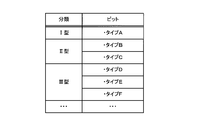
- the pit patterns observed for pit pattern shapes classified into six types (from I type to V type) according to the type of lesion from the normal state. Is determined according to which classification is similar.
- Patent Document 2 describes an apparatus for acquiring a three-dimensional optical tomographic image using an endoscope and an optical probe, and based on the three-dimensional optical tomographic image, a plane perpendicular to the depth direction of biological tissue is described.
- a method is disclosed in which an XY screen image is cut out at a plurality of depth positions and a pit pattern shape is highlighted from the average image.
- Patent Document 1 The process of Patent Document 1 is based on the assumption that when the distance from the imaging unit to the subject (the surface of the living body) is long, the image is darkly captured because the amount of reflected light reflected from the surface of the living body is reduced. Therefore, for example, even if there is no direct relation to the minute unevenness on the surface of the living body, such as the shadow area around the bright spot or the structure in the foreground, or the blood vessel and the surrounding mucous membrane, the uneven structure is It will be erroneously detected.
- the case where the pit pattern diagnosis is performed is a state where a region suspected to be a lesion is already found by screening observation, and corresponds to a state where close inspection is performed with the tip of the endoscope approaching the region.
- the captured image of the surface of the living body to be observed has a large magnification, so that the influence of relative movement between the living body and the imaging unit is large.
- a scanning operation of the optical probe is required, and therefore pits in the XY image caused by relative movement between the living body and the imaging unit. Shape deformation cannot be ignored. For this reason, there is a problem that the similarity with the model pattern used for pit pattern detection cannot be stably calculated, and an accurate image cannot be acquired.
- an image processing device an electronic apparatus, an endoscope device, a program, and image processing that accurately detect uneven portions of a subject based on known characteristic information and distance information about the subject A method can be provided.
- an image acquisition unit that acquires a captured image including an image of a subject by imaging of the imaging unit, and a distance that acquires distance information based on a distance from the imaging unit to the subject at the time of imaging
- An information acquisition unit a known property information acquisition unit that acquires known property information that is information representing a known property related to the structure of the subject, and the captured subject based on the distance information and the known property information
- the present invention relates to an image processing apparatus including an unevenness specifying unit that performs an unevenness specifying process for specifying an unevenness part of the subject that matches a characteristic specified by the known characteristic information.
- the distance information to the subject and the known characteristic information are acquired, and the uneven portion of the subject that matches the characteristic specified by the known characteristic information is specified.
- the concavo-convex portion is specified by a technique using image processing.
- Another aspect of the present invention relates to an electronic apparatus including the image processing apparatus.
- Another aspect of the present invention relates to an endoscope apparatus including the above-described image processing apparatus.
- the uneven portion of the living body can be specified in the captured image, so that it is possible to easily find a lesioned portion and the like.
- Another aspect of the present invention relates to a program that causes a computer to function as each of the above-described units.
- known characteristic information which is information representing a known characteristic related to the structure of the subject, and based on the distance information and the known characteristic information, from the photographed subject based on the known characteristic information.
- the present invention relates to an image processing method for performing unevenness specifying processing for specifying the uneven portion of the subject that matches the specified characteristics.
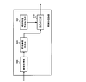
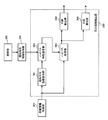
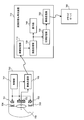
- FIG. 1 is a system configuration example of an image processing apparatus.
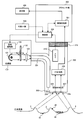
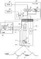
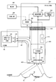
- FIG. 2 is a configuration example of an endoscope apparatus including the image processing apparatus according to the first embodiment.
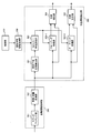
- FIG. 3 is a configuration example of an image processing unit according to the first embodiment.
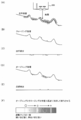
- FIG. 4A to FIG. 4F are diagrams for explaining extraction processing according to the first embodiment.
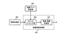
- FIG. 5 is a configuration example of a distance information acquisition unit and an unevenness information extraction unit according to the first embodiment.
- FIG. 6 is a configuration example of an endoscope apparatus including an image processing apparatus according to the second embodiment.
- FIG. 7 is a configuration example of an image processing unit according to the second embodiment.
- FIG. 8A to FIG. 8D are diagrams for explaining extraction processing according to the second embodiment.
- FIG. 9 is a configuration example of the unevenness information extraction unit of the second embodiment.
- FIG. 10 is a configuration example of an endoscope apparatus including an image processing apparatus according to the third embodiment.
- FIG. 11 is a configuration example of an image processing unit according to the third embodiment.
- FIG. 12 is a configuration example of the unevenness information extraction unit of the third embodiment.
- FIG. 13 is a configuration example of a distance information acquisition unit according to the third embodiment.
- FIG. 14 is a configuration example of an image recording / reproducing apparatus including the image processing apparatus according to the fourth embodiment and a capsule endoscope.
- FIG. 15 is a configuration example of an image processing unit according to the fourth embodiment.
- FIG. 16 is a configuration example of an image processing unit according to the fifth embodiment.
- FIG. 17A is an example of a cross-sectional view of a gland duct structure
- FIG. 17B is an example of a gland duct structure in a captured image.
- 18A and 18B are explanatory diagrams of processing for obtaining surface shape information.
- 19A and 19B show examples of the reference pattern and the correction pattern.
- FIG. 20 is a configuration example of the surface shape calculation unit.
- FIG. 21 is a configuration example of a classification processing unit according to the fifth embodiment.
- FIG. 22 shows an example of a classification map that is a result of the classification process.
- FIG. 23 is a configuration example of an endoscope apparatus including an image processing apparatus according to the sixth embodiment.
- FIG. 24 is a configuration example of a classification processing unit according to the sixth embodiment.
- FIG. 25 shows an example in which a plurality of reference patterns are held.
- FIG. 26A to FIG. 26D are examples of classification maps that are the results of classification processing when a plurality of reference patterns are used.
- FIGS. 27A to 27F are diagrams for explaining similarity calculation processing. 28A to 28F show examples of pit patterns.
- the image processing apparatus obtains a captured image including an image of a subject by imaging with an imaging unit (such as the imaging unit 200 in FIG. 2 described later).
- An acquisition unit 390 a distance information acquisition unit 340 that acquires distance information based on a distance from the imaging unit to the subject at the time of imaging, and a known characteristic that acquires known characteristic information that is information representing a known characteristic related to the structure of the subject
- the concave / convex identification process for performing the concave / convex identification process for identifying the concave / convex part of the subject that matches the characteristic specified by the known characteristic information from the subject captured in the captured image.
- Part 310 is included.
- the concavo-convex portion specified by the concavo-convex specifying portion 310 is a minute concavo-convex structure such as a groove or a polyp having a given dimension (width, depth, height, etc.) specified by known characteristic information. It may be the gland duct structure (pit pattern) on the surface of the living body described above.
- the distance information acquired by the distance information acquisition unit 340 is information corresponding to the distance from the imaging unit to the subject, as shown in FIG. In particular, it is information representing the structure of the surface). That is, the distance information includes a minute uneven structure on the surface of the subject.
- the distance information includes information on other structures of the subject surface.
- many living bodies observed with an endoscope apparatus are luminal, such as the esophagus and the large intestine.
- the distance represented by the distance information includes a change in value according to the situation.
- the distance information includes various other structures, but the distance information as a whole represents a structure in which the distance from the imaging unit to the subject increases in the right direction.
- the surface of the subject may include a concavo-convex structure different from the concavo-convex structure desired to be specified by the method of the present embodiment.
- a wrinkle structure is seen on the surface of a living body such as the stomach or large intestine as shown in FIGS.
- the distance information includes information on the heel structure, but the uneven portion assumed in the observation using the endoscope apparatus in the present embodiment is naturally seen on the surface of such a living body.
- the structure to be obtained is a minute uneven structure having different dimensions.
- the distance information includes distance fluctuations corresponding to the curved surface of a circular pipe, grooves that have been dug to give the pipe a given function, and the severity. Although information such as scratches that may be overlooked because of its low level may be included, it is preferable to extract useful concavo-convex structures as extracted concavo-convex information by excluding them.
- the present applicant proposes a method of acquiring known characteristic information, which is information representing a known characteristic related to the structure of the subject, and identifying the uneven portion of the subject that matches the characteristic specified by the known characteristic information in the captured image.
- the known characteristic information is information that can separate a useful structure in the present embodiment from a structure that is not so, among the structures on the surface of the subject.
- the information such as the curvature of the living body wall surface and the dimension information of the eyelids are held as known characteristic information, and information that matches the known characteristic information is excluded from the distance information.
- the uneven portion may be specified by using the information as the extracted uneven information.
- the dimension information of the useful concavo-convex structure may be used as the known characteristic information.
- the known characteristic information includes information corresponding to the exclusion target and information corresponding to the extraction target.
- the “characteristic specified by the known characteristic information” here represents a characteristic that corresponds to the extraction target and does not correspond to the exclusion target. For example, a value that can clearly separate the extraction target and the exclusion target is defined as a boundary. It is a characteristic having a value (or having a value in a range determined by the boundary value).
- the size of a typical wrinkle or the dimension of a useful uneven structure may differ depending on the region to be observed (the stomach for the upper digestive system, the large intestine for the lower digestive system, etc.). is assumed. Therefore, it is desirable that the known characteristic information is not one piece of information but can be selected and changed according to the observation target.
- the processing is adaptively changed according to the value (distance) represented by the distance information.
- the extraction process parameter used when extracting the extracted unevenness information from the distance information is adaptively controlled according to the value of the distance information.
- a pit pattern will be described as an example.
- the present embodiment can be widely applied to a method for identifying a structure by a matching process using a two-dimensional pattern, and a pattern other than a pit pattern can be used. It is.
- the pit pattern on the surface of the living body depends on whether it is in a normal state or an abnormal state. It is known that the shape changes depending on the like. For example, in the case of a normal mucous membrane, the pit pattern is nearly circular as shown in FIG. 28A, and when the lesion progresses, the star-shaped pattern in FIG. 28B, FIG. 28C, and FIG. If it progresses further, the pit pattern disappears as shown in FIG. 28 (F). Therefore, it is possible to determine the state of the subject by holding these typical patterns as reference patterns and determining the degree of similarity between the surface of the subject captured in the captured image and the reference pattern. . A method for assisting such pit pattern diagnosis is disclosed in Patent Document 2 and the like.
- the typical shape of the pit pattern does not always match the appearance of the pit pattern on the captured image.
- the living body includes a wall surface of a luminal structure and a structure such as a heel. Therefore, it is fully possible that the optical axis direction of the imaging unit and the surface of the living body are not orthogonal to each other. In this case, even if there is a circular pit pattern on the surface of the living body, the captured image has an elliptical shape or the like. Can be considered.
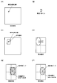
- FIG. 17 (A) consider a case where a subject having an eyelid 2 on the surface of the living body and a circular pit pattern (normal gland duct 40) seen on the surface of the eyelid 2 is imaged.
- FIG. 17B due to the angle formed by the optical axis direction of the imaging unit and the surface of the living body, the originally circular pit pattern is observed with various deformations. become.
- the applicant acquires surface shape information representing the structure of the subject surface based on the known characteristic information and distance information, and the uneven portion is obtained by classification processing using a classification criterion set using the surface shape information. Suggest a method to identify.
- the surface shape information represents a general structure of the surface of the subject, and is, for example, the curved surface shown in FIG. 18B (distance information excluding the minute uneven structure in FIG. 18A). Alternatively, it may be a set of normal vectors of the curved surface.
- the surface shape information By using the surface shape information, as shown in FIGS. 19A and 19B, if a reference pattern exists in the subject surface area to be processed, how is the pattern on the captured image? It can be estimated whether it is deformed and observed. In other words, whether or not a pit pattern corresponding to the reference pattern can be seen on the surface of the subject is determined by the pattern after the deformation processing is performed based on the surface shape information (hereinafter referred to as a correction pattern) as shown in FIG.
- the classification process may be performed using as a classification criterion.
- the known characteristic information is a pit pattern, and specifically, information such as a pit shape and size.
- the endoscope apparatus will be described as an example as shown in FIG. 2, but as described above with reference to FIG. 1, the present embodiment is applicable to an image processing apparatus that is not limited to the endoscope apparatus.
- the first to fourth embodiments correspond to methods for specifying a minute concavo-convex structure using the extracted concavo-convex information.
- a method of acquiring distance information based on parallax information obtained from captured images corresponding to a plurality of viewpoints and extracting extracted unevenness information from distance information by morphological processing will be described.
- the extraction processing parameter is the size of the structural element used for the morphological processing.
- a method of acquiring distance information using the Time of Flight method and extracting extracted unevenness information by filter processing (particularly, low-pass filter processing) will be described.
- the extraction process parameter is a parameter that determines the frequency characteristics of the filter used for the filter process.
- distance information is acquired by combining a method based on parallax information obtained from captured images corresponding to a plurality of viewpoints, and a Time of Flight method, and by filtering (particularly, high-pass filtering). A method for extracting the extracted unevenness information will be described.
- filtering particularly, high-pass filtering
- the combination of the distance information acquisition process and the extracted unevenness information extraction process can be variously changed. That is, a method based on disparity information and filter processing may be combined, or a Time-of-Flight method and morphological processing may be combined. In addition, this embodiment is realizable by arbitrary combinations of the method mentioned above.
- a method for identifying a concavo-convex portion by generating classification criteria using surface shape information and performing classification processing.
- a method is described in which a normal state pit pattern is held as a reference pattern, and a classification process for classifying each region of a subject of a captured image as a normal state is performed.
- a plurality of pit patterns (for example, a normal state and one or a plurality of abnormal pit patterns) are stored as reference patterns, and each region of the subject of the captured image is set to any state.
- a method for performing a classification process for classifying whether the classification is applicable (or not applicable) will be described.
- a second correction pattern obtained by acquiring a second reference pattern from a captured image using a correction pattern obtained by deforming the reference pattern and deforming the second reference pattern with the surface shape information.
- FIG. 2 shows a configuration example of an endoscope apparatus including an image processing apparatus (corresponding to the image processing unit 301) according to the first embodiment.
- the endoscope apparatus constituting the first embodiment includes a light source unit 100, an imaging unit 200, a processor unit 300, a display unit 400, and an external I / F unit 500.
- the light source unit 100 includes a white light source 101, a rotating color filter 102 having a plurality of spectral transmittances, a rotation driving unit 103 for driving the rotating color filter 102, and light having spectral characteristics from the rotating color filter 102 as a light guide fiber. And a condensing lens 104 for condensing light on the incident end face 201.
- the rotary color filter 102 is composed of three primary colors, a red color filter, a green color filter, a blue color filter, and a rotary motor.
- the rotation driving unit 103 rotates the rotating color filter 102 at a predetermined number of rotations in synchronization with the imaging period of the imaging elements 206 and 207 based on a control signal from the control unit 302 of the processor unit 300. For example, when the color filter is rotated 20 times per second, each color filter crosses the incident white light at intervals of 1/60 second, and the image sensors 206 and 207 have the light of each of the three primary colors (at 1/60 second intervals). The reflected light from the observation target for R, G, or B) is imaged, and the transfer of the image is completed. That is, this embodiment is an example of an endoscope apparatus in which an R image, a G image, and a B image are imaged in a frame sequential manner at 1/60 second intervals, and the actual frame rate is 20 fps.
- the imaging unit 200 is formed to be elongated and bendable so that it can be inserted into a body cavity such as the stomach or the large intestine.
- the imaging unit 200 includes a light guide fiber 201 for guiding the light collected by the light source unit 100, an illumination lens 203 for diffusing the light guided to the tip by the light guide fiber 201 and irradiating the observation target, Objective lenses 204 and 205 for collecting the reflected light returning from the observation target, imaging elements 206 and 207 for detecting the focused imaging light, and photoelectrically converted analog signals from the imaging elements 206 and 207 are converted into digital signals.
- An A / D conversion unit 209 for converting the image to the camera a memory 210 in which unique information including scope ID information and manufacturing variation of the imaging unit 200 is recorded, and a processor 212 and a connector 212 that is detachable.
- the image sensors 206 and 207 are monochrome single-plate image sensors, and a CCD, a CMOS, or the like can be used.
- the objective lenses 204 and 205 are disposed at positions separated by a predetermined distance, and are disposed at positions where a predetermined parallax image (hereinafter referred to as a stereo image) can be captured. Is imaged. Further, the left image and the right image output from the image sensors 206 and 207 are converted into digital signals by the A / D conversion unit 209 and output to the image processing unit 301.
- the memory 210 is connected to the control unit 302, and unique information including scope ID information and manufacturing variations is sent to the control unit 302.
- the processor unit 300 includes an image processing unit 301 and a control unit 302.
- the display unit 400 is a display device capable of displaying a moving image such as a CRT or a liquid crystal monitor.
- the external I / F unit 500 is an interface for performing input from the user to the endoscope apparatus, a power switch for turning on / off the power, a shutter button for starting a photographing operation, and photographing. It includes a mode changeover switch (for example, a switch for selectively emphasizing the uneven portion on the surface of the living body) for switching between modes and other various modes.
- the external I / F unit 500 outputs input information to the control unit 302.
- the lesioned part 10 is a concave-type slightly depressed early lesion
- the lesion 20 is a bulge-type slightly protruding early lesion
- the lesioned part 30 is an early lesion with an irregular mucosal surface.
- the uneven part similar to the uneven part seen in the lesion part is also found in the normal part.
- the method of the present embodiment is not for detecting a lesion part itself, but for obtaining extraction unevenness information useful for lesion detection or the like, and therefore, an uneven part included in a lesion part and an uneven part included in a normal part Are not handled separately.
- the image processing unit 301 includes an image acquisition unit 390, an image configuration unit 320, a distance information acquisition unit 340 (distance map calculation unit), a known characteristic information acquisition unit 350, a concavo-convex specification unit 310, and an enhancement processing unit 330.
- Reference numeral 310 further includes an unevenness information extraction unit 360 and a specific processing unit 370.
- a stereo image composed of a left image and a right image output from the imaging elements 206 and 207 of the imaging unit 200 is acquired by the image acquisition unit 390, and the acquired stereo image is sent to the image configuration unit 320 and the distance information acquisition unit 340. Entered.
- the image composing unit 320 performs predetermined image processing (OB processing, gain processing, ⁇ processing) on the captured stereo image so as to be an image that can be output to the display unit 400, and outputs the processed image to the enhancement processing unit 330.
- the distance information acquisition unit 340 uses the left image constituting the captured stereo image as a reference image, performs a matching operation with the local region of the right image on the epipolar line passing through the target pixel located at the center of the local region of the left image, The position having the maximum correlation is calculated as the parallax.
- the distance information acquisition unit 340 further converts the calculated parallax into a distance in the Z direction to acquire distance information (a distance map in a narrow sense), and the acquired distance information is the unevenness information extraction unit 360 of the unevenness specifying unit 310. Is output.
- the known characteristic information acquisition unit 350 acquires known characteristic information from the control unit 302 (or a storage unit (not shown)). Specifically, the size of the unevenness part specific to the living body to be extracted from the surface of the living body due to the lesion (dimension information such as width, height, depth, etc.), and the size of the site-specific lumen and fold based on the observation site information (Dimension information such as width, height and depth) is acquired as known characteristic information.
- the observation part information is information representing the part to be observed, which is determined based on the scope ID information input from the memory 210 to the control unit 302, and the observation part information may be included in the known characteristic information. Good.
- the observation site is information that is determined to be the esophagus, stomach, and duodenum. Since the dimension information of the uneven part to be extracted and the dimension information of the lumen and the heel specific to the part differ depending on the part, the known characteristic information acquisition unit 350 obtains the standard information acquired based on the observation part information. Information such as the size of the lumen and the eyelid is output to the unevenness information extraction unit 360.
- the observation site information is not limited to that determined by the scope ID information, and may be determined by other methods such as selection using a switch operable by the user in the external I / F unit 500.
- the unevenness information extraction unit 360 determines an extraction process parameter based on the known characteristic information, and performs an extraction process of the extracted unevenness information based on the determined extraction process parameter.
- the unevenness information extraction unit 360 performs a low-pass filter process of a predetermined size of N ⁇ N pixels on the input distance information, and extracts rough distance information. Based on the extracted rough distance information, the extraction processing parameter is adaptively determined. Details of the extraction processing parameter will be described later.
- the morphological kernel size structure element size
- the morphological kernel size adapted to the distance information at the plane position orthogonal to the distance information of the distance map, or the distance of the plane position It may be a low-pass filter adapted to information or a high-pass filter adapted to the planar position. That is, it is change information for changing an adaptive non-linear and linear low-pass filter or high-pass filter according to the distance information.
- the concavo-convex information extraction unit 360 extracts only the concavo-convex part of a desired size that actually exists in the subject by performing an extraction process based on the determined extraction processing parameter. These extracted concavo-convex portions are associated with the captured image in the specific processing unit 370.
- the extracted unevenness information here is information such as that shown in FIG. 4C and FIG. 4E, which will be described later, and it is also possible that a predetermined process is required for association with the captured image. For example, when the extracted unevenness information is acquired as an uneven image having a size that is a constant multiple of the captured image, the specific processing unit 370 converts the position of the uneven portion on the uneven image into a position on the captured image. A scaling process of the uneven image is performed.
- unevenness information extraction unit 360 when extracted unevenness information (unevenness image) having the same size as the image output from the image configuration unit 320 is acquired, the specific unevenness information 370 is omitted and the extraction unevenness information is omitted. Information may be output to the enhancement processing unit 330.
- the enhancement processing unit 330 performs desired enhancement processing (for example, enhancement for luminance, hue or saturation enhancement for color) corresponding to the specified uneven portion, and a captured image (for example, the image configuration unit 320). Left image as a reference for parallax calculation in the left and right images output from), and outputs only the processed left image to the display unit 400. That is, a 2D image is displayed without outputting as a stereoscopic image.
- the display image in the present embodiment is not limited to this, and a highlighted stereoscopic image may be output. Alternatively, both the highlighted 2D image and the stereoscopic image that is not highlighted may be output to enable switching display.
- the extraction process parameters in FIGS. 4A to 4F are the diameters of the structural elements (spheres) used for the opening process and the closing process of the morphological process.
- FIG. 4A is a diagram schematically showing a cross section in the vertical direction of the surface of the living body of the subject and the imaging unit 200. It is assumed that wrinkles 2, 3, and 4 on the surface of the living body are wrinkles on the stomach wall, for example. Further, it is assumed that the early lesions 10, 20, and 30 are formed on the surface of the living body.
- What is desired to be realized by the extraction process parameter determination process in the unevenness information extraction unit 360 is to extract only the early lesions 10, 20, and 30 without extracting the folds 2, 3, and 4 from the surface of such a living body. It is to determine an extraction processing parameter.
- the size of the concavo-convex part specific to the living body to be extracted from the control part 302 dimension information such as width, height, depth, etc.
- the part-specific lumen based on the observation part information dimension information such as width, height and depth
- the diameter of the sphere is set to be smaller than the size of the region-specific lumen and fold based on the observation region information, and larger than the size of the unevenness portion specific to the living body to be extracted due to the lesion. More specifically, it is preferable to set the diameter to be equal to or larger than the size of the concavo-convex part inherent to the living body to be extracted due to the lesion with a diameter less than half of the size of the eyelid.
- FIGS. 4 (A) to 4 (F) An example in which a sphere satisfying the above conditions is used for the opening process and the closing process is illustrated in FIGS. 4 (A) to 4 (F).
- FIG. 4B shows the surface of the living body after the closing process.
- an appropriate extraction processing parameter size of the structural element
- FIG. 4 (D) shows the surface of the living body after the opening process, and it can be seen that information obtained by removing the convex portion of the irregular portion of the dimension to be extracted is obtained. Therefore, by taking the difference between the information obtained by the opening process and the original biological surface, only the convex portion of the biological surface as shown in FIG.
- an opening process and a closing process using spheres of the same size may be performed on the actual living body surface, but a stereo image is formed on the image sensor as a smaller area as the distance information increases. Therefore, in order to extract a concavo-convex portion of a desired size, the diameter of the sphere may be increased when the distance information is close, and the diameter of the sphere may be decreased when the distance information is far.
- FIG. 4 (F) shows that control is performed so as to change the diameter of the sphere with respect to the average distance information when the opening process and the closing process are performed on the distance map. That is, in order to extract a desired uneven portion from the distance map, it is necessary to correct the actual size of the living body surface with the optical magnification in order to match the size of the pixel pitch on the image formed on the image sensor. Therefore, the unevenness information extraction unit 360 may acquire the optical magnification and the like of the imaging unit 200 determined based on the scope ID information from the memory 210.
- the distance information acquisition unit 340 includes a stereo matching unit 341 and a parallax / distance conversion unit 342.
- the unevenness information extracting unit 360 includes a local average distance calculating unit 361, a morphological characteristic setting unit 362, a closing processing unit 363-1, an opening processing unit 363-2, a concave portion extracting unit 364, and a convex portion extracting unit 365.
- the stereo image output from the imaging unit 200 is input to the stereo matching unit 341, and the processing target pixel and its surrounding area (block of a predetermined size) are block-matched on the epipolar line with respect to the right image using the left image as a reference image.
- the calculated parallax information is converted into distance information by the parallax / distance conversion unit 342. This conversion includes a process for correcting the optical magnification of the imaging unit 200.
- the converted distance information is output to the local average distance calculation unit 361 as a distance map composed of pixels of the same size as the stereo image in a narrow sense.
- the local average distance calculation unit 361 calculates an average value of, for example, 3 ⁇ 3 pixels with respect to the input distance map, and calculates an average distance in a local region.
- the calculated average distance is input to the morphological property setting unit 362, and the size (dimension information such as width, height, depth, etc.) of the living body specific to be extracted from the control unit 302 and the observation site
- the diameter (extraction processing parameter in the present embodiment) of the sphere used for the opening process and the closing process is determined based on the size of the lumen and the eyelid specific to the region based on the information (dimension information such as width, height, and depth).
- the diameter information of the determined sphere is input to the closing processing unit 363-1 and the opening processing unit 363-2 as a diameter map having the same number of pixels as the distance map.
- the closing processing unit 363-1 and the opening processing unit 363-2 perform the closing process and the opening process by changing the diameter in units of pixels based on the diameter map.
- the processing result of the closing processing unit 363-1 is output to the recess extraction unit 364. Further, the processing result of the opening processing unit 363-2 is output to the convex portion extraction unit 365.
- the distance map before and after the closing process is input to the recessed part extracting unit 364, and a recessed part image in which only a desired recessed part is extracted by subtracting the distance map after the closing process from the distance map before the closing process is output.
- a distance map before and after the opening process is input to the convex part extraction unit 365, and a convex part image in which only a desired convex part is extracted by subtracting the distance map after the opening process from the distance map before the opening process is obtained. Is output.
- a living body-specific uneven portion to be extracted due to a lesion can be extracted with high accuracy without being affected by a wrinkle or a lumen shape unique to an observation site. For example, it is possible to selectively highlight an uneven portion caused by a lesion.
- the image processing apparatus includes an image acquisition unit 390 that acquires a captured image including an image of a subject by imaging by the imaging unit 200, and imaging at the time of imaging.
- a distance information acquisition unit 340 that acquires distance information based on a distance from the unit 200 to the subject
- a known characteristic information acquisition unit 350 that acquires known characteristic information that is information representing a known characteristic related to the structure of the subject, distance information
- an unevenness specifying unit 310 that performs unevenness specifying processing for specifying an uneven part of the subject that matches the characteristic specified by the known characteristic information from the subject captured in the captured image is included.
- the distance information is various pieces of information acquired based on the distance from the imaging unit 200 to the subject.
- a distance based on an arbitrary point on a surface connecting two lenses that generate parallax is a distance.
- Information can be used.
- the Time-of-Flight method described later in the second embodiment or the like for example, a distance based on each pixel position on the image sensor surface is acquired as distance information.
- a reference point for distance measurement is set in the imaging unit 200, but the reference point is set at an arbitrary location other than the imaging unit 200, for example, an arbitrary location in a three-dimensional space including the imaging unit and the subject. It may be set, and information when such a reference point is used is also included in the distance information of this embodiment.
- the distance from the imaging unit 200 to the subject can be, for example, the distance in the depth direction from the imaging unit 200 to the subject.
- the distance in the optical axis direction of the imaging unit 200 may be used.
- the viewpoint is set in a direction perpendicular to the optical axis as shown in FIG. (In the example of FIG. 4A, the distance from the imaging unit 200 to the subject in the vertical direction indicated by an arrow) may be used.
- the distance information acquisition unit 340 converts the coordinates of each corresponding point in the first coordinate system with the first reference point of the imaging unit 200 as the origin into a second coordinate in the three-dimensional space by a known coordinate conversion process.
- the distance may be measured based on the coordinates of the corresponding point in the second coordinate system with the reference point as the origin and converted into the coordinates of the corresponding point.
- the distance from the second reference point to each corresponding point in the second coordinate system is the distance from the first reference point to each corresponding point in the first coordinate system, that is, “from the imaging unit to each corresponding point. The distance between the two is the same.
- the distance information acquisition unit 340 has a virtual position at a position where a magnitude relationship similar to the magnitude relationship of the distance values between pixels on the distance map acquired when the reference point is set in the imaging unit 200 can be maintained.
- distance information based on the distance from the imaging unit 200 to the corresponding point may be acquired. For example, when the actual distances from the imaging unit 200 to the three corresponding points are “3”, “4”, and “5”, the distance information acquisition unit 340 maintains the magnitude relationship of the distance values between the pixels. You may acquire "1.5", “2", and "2.5" by which those distances were equally halved.
- the unevenness information extraction unit 360 uses a different parameter as the extraction processing parameter as compared with the case where the reference point is set in the imaging unit 200. This is because the distance information needs to be used for the determination of the extraction processing parameter, and therefore, the method for determining the extraction processing parameter also changes when the representation method of the distance information changes due to the change of the reference point of the distance measurement. For example, as described above in the present embodiment, in the case where extraction unevenness information is extracted by morphological processing, the size (for example, the diameter of a sphere) of a structural element used for the extraction processing is adjusted, and the adjusted structural element is used. Then, the unevenness extraction process is performed.
- the size for example, the diameter of a sphere
- the present invention is not limited thereto. At that time, since it is not necessary to use a method of changing the subject side such as pigment dispersion, it is not necessary to consider the reduction in the visibility of subjects other than the object to be emphasized, the invasive problem when targeting a living body, etc. There is also an advantage.
- the unevenness specifying unit 310 extracts information representing the uneven portion of the subject that matches the characteristics specified by the known characteristic information from the distance information based on the distance information and the known characteristic information as extracted unevenness information. Part 360 may be included. Then, the unevenness specifying unit 310 performs unevenness specifying processing based on the extracted unevenness information.
- extracted unevenness information for example, information shown in FIG. 4C or FIG. 4E
- distance information for example, information shown in FIG. 4A
- the extracted unevenness information is used.
- grooved part is located can be performed.
- the extracted unevenness information has, in a narrow sense, a distance map or the number of pixels (for example, the same number of pixels) corresponding to the image formed by the image configuration unit 320, and each pixel value is a value corresponding to the unevenness.
- An uneven image may be used.
- the value corresponding to the unevenness for example, the convex portion has a positive value and the concave portion has a negative value. The higher the height of the convex portion and the deeper the concave portion, the larger the absolute value can be considered.
- the extracted unevenness information is not limited to the unevenness image, and may be other types of information.
- the unevenness information extraction unit 360 may determine an extraction process parameter based on the known characteristic information, and extract the uneven part of the subject as the extracted unevenness information based on the determined extraction process parameter.
- extraction processing for example, separation processing
- the specific method of the extraction process may be the morphological process described above in this embodiment, the filter process described later, or the like.
- various methods included in the distance information it is necessary to control to exclude other structures (for example, a structure unique to a living body such as a bag) while extracting information on a desired uneven portion from the information on the structure.
- control is realized by setting extraction processing parameters based on the known characteristic information.
- the known characteristic information acquisition unit 350 may acquire, as known characteristic information, type information indicating the type of the subject, and unevenness characteristic information that is information related to the unevenness portion of the subject associated with the type information. Then, the unevenness information extraction unit 360 determines an extraction processing parameter based on the type information and the unevenness characteristic information, and extracts the unevenness portion of the subject as the extracted unevenness information based on the determined extraction processing parameter.
- the type information is information for specifying the type of subject.
- information for specifying an apparatus to be observed may be used.
- the information which specifies the kind in a narrower range may be sufficient, for example, the information which specifies what thickness pipe is observed among several pipes with different thickness contained in an apparatus may be sufficient.
- the unevenness characteristic information is information for specifying the unevenness characteristics of the subject to be extracted from the distance information. Specifically, information including at least one of information indicating the characteristics of the unevenness to be excluded among the unevenness included in the distance information and information indicating the characteristics of the unevenness to be extracted is included.
- the image processing apparatus of the present embodiment stores a plurality of unevenness characteristic information for each type information, and determines an appropriate extraction processing parameter by selecting an appropriate one according to the acquired type information.
- the unevenness characteristic information may be one piece of information serving as a reference, or the one value may be used after being converted according to the type information.
- the captured image is an in-vivo image obtained by imaging the inside of the living body
- the known characteristic information acquisition unit 350 includes part information indicating which part of the living body the subject corresponds to and information on the uneven part of the living body. Certain uneven characteristic information may be acquired as known characteristic information.
- the unevenness information extraction unit 360 determines an extraction processing parameter based on the part information and the unevenness characteristic information, and extracts the unevenness portion of the subject as the extracted unevenness information based on the determined extraction processing parameter.
- the part information related to the part of the subject of the in-vivo image is changed to the known characteristics. It can be acquired as information.
- the method of this embodiment is applied to an in vivo image, it is assumed that an uneven structure useful for detection of an early lesion is extracted as extracted unevenness information.
- the characteristics (for example, dimension information) of the concavo-convex part may vary depending on the part.
- the structure such as wrinkles
- the process is performed based on the part information.
- a storage unit (not shown) stores first to Nth unevenness characteristic information corresponding to each of the first to Nth parts of the living body, and When the subject information specifies that the subject corresponds to the kth part, the unevenness information extraction unit 360 uses the kth unevenness characteristic information among the first to Nth unevenness characteristic information to perform the extraction. Processing parameters may be determined.
- a storage unit (not shown) stores reference unevenness characteristic information as the unevenness characteristic information, and the unevenness information extraction unit 360 performs a conversion process on the reference unevenness characteristic information based on the part information. The extraction process parameter may be determined using the unevenness characteristic information after the conversion process.
- the unevenness information extraction unit 360 determines the size of the structural element used for the opening process and the closing process based on the known characteristic information as an extraction process parameter, and performs the opening process using the structural element of the determined size,
- the unevenness portion of the subject may be extracted as the extracted unevenness information by performing a closing process.
- the extraction process parameter at that time is the size of the structural element used in the opening process and the closing process. Since a sphere is assumed as a structural element in FIG. 4A, the extraction processing parameter is a parameter that represents the diameter of the sphere. Specifically, as described above, when a process using a structural element is performed on a shape to be excluded such as a heel (when a sphere is slid on the surface in FIG. 4A), the shape is The size of the structural element is determined so as not to be crushed (the sphere moves following the shape).
- the concavo-convex part to be extracted is subjected to the processing by the structural element as the extracted concavo-convex information, the concavo-convex part is eliminated (when it is slid from the top, it does not enter the concave part or is slid from the bottom.
- the size of the structural element may be determined so that it does not enter the convex portion. Since the morphological process is a widely known technique, detailed description thereof is omitted.
- the unevenness information extraction unit 360 may set the size of the structural element that is the extraction process parameter to be smaller as the value of the distance information corresponding to the processing target pixel of the opening process and the closing process is larger.
- the known characteristic information is a known characteristic relating to the structure of the subject, it is assumed that the known characteristic information is expressed in an actual size (for example, a size determined in units such as micrometers and millimeters) when considered in the real space.
- an actual size for example, a size determined in units such as micrometers and millimeters
- the subject having the same actual size for example, a groove having the same width
- the known characteristic information must be converted between the actual size and the apparent size on the distance information (if the distance information is a distance map expressed in units of pixels, the size determined in units of pixels).
- the conversion is performed by changing the extraction processing parameter according to the value of the distance information. Specifically, the larger the distance, the smaller the uneven portion to be extracted, so the size of the structural element may be set small.
- the unevenness information extraction unit 360 acquires the imaging magnification information from the imaging unit 200, and It is desirable to perform conversion processing based on the imaging magnification.
- the subject has a global three-dimensional structure and a local concavo-convex structure as compared with the global three-dimensional structure.
- the concavo-convex information extraction unit 360 includes a local three-dimensional structure and a local Of the general concavo-convex structure, the concavo-convex part of the subject that matches the characteristic specified by the known characteristic information may be extracted as the extracted concavo-convex information.
- the captured image is an in-vivo image obtained by imaging the inside of the living body, and the subject is formed in a general three-dimensional structure of the living body, which is a lumen structure inside the living body, and a tubular structure.
- the unevenness information extraction unit 360 has a local uneven structure compared to the original structure, and the unevenness information extraction unit 360 matches the characteristics specified by the known characteristic information among the global three-dimensional structure and unevenness included in the object. May be extracted as extracted unevenness information.
- the method of the present embodiment is a global three-dimensional structure included in the distance information (here, refers to a structure having a lower spatial frequency than the uneven portion), and It becomes possible to implement
- an uneven portion useful for finding an early lesion is selected as an extraction target. That is, it is not necessary to extract the three-dimensional structure unique to the living body, such as a structure inherent to the living body-specific wrinkles or the curvature of the wall surface, and the unevenness information extracting unit 360 may extract the unevenness portion by removing them.
- the distance information acquisition unit 340 may acquire, as distance information, a distance map that associates information regarding the distance from the imaging unit to the subject imaged by each pixel in each pixel of the acquired captured image. .
- the distance map is a subordinate concept of distance information.
- each point for example, each pixel
- the distance (depth / depth) is in the Z axis direction to the subject. This is a map with the distance (depth / depth) as the value of the point.
- the distance information, the extracted unevenness information extracted from the distance information, and the subject image (the image acquired by the image configuration unit 320) subjected to the image configuration processing or the like are easily associated with each pixel. be able to. Therefore, it is possible to easily grasp at which position in the subject image the uneven portion to be extracted is present, and the pixel to be emphasized when performing the emphasis processing of the uneven portion using the enhancement processing unit 330 or the like. It is easy to determine pixels that are not.
- the imaging unit 200 has a plurality of viewpoints
- the image acquisition unit 390 acquires a plurality of captured images corresponding to each of the plurality of viewpoints via the imaging unit 200
- the distance information acquisition unit 340 The distance information may be acquired based on the parallax information obtained from the plurality of acquired captured images.
- the image sensor (206 and 207 in FIG. 2) a widely used element such as a Bayer array single plate element can be used.
- a widely used element such as a Bayer array single plate element can be used.
- the electronic device here is hardware for creating the imaging unit 200 and distance information (in this embodiment, a stereo optical system, but a laser light source 105 or a distance measurement sensor in a Time of Flight system described later) 214 may be included, or only one of them may be included, or both may not be included.
- the electronic device of this embodiment may be a device (for example, a PC or a server) that acquires information from an artificial satellite, for example. In this case, the distance from the artificial satellite to Mt. Fuji is measured by emitting a laser from the artificial satellite, and the electronic device according to the present invention acquires an image of the Mt.
- the electronic device acquires information indicating the geometric information of the caldera (concave portion) on Mt. Fuji as known characteristic information from the recording unit, and based on the characteristics, the caldera part formed on Mt. Fuji on the image It is conceivable to perform processing such as recognizing.
- an endoscope apparatus that detects uneven portions by the method of the present embodiment.
- a minute uneven portion of a living body is useful for finding an early lesion portion, but conventionally, the detection accuracy of the uneven portion is not sufficient or image processing is not performed.
- Techniques such as highly invasive pigment spraying were used for the subjects.
- the method of the present embodiment it is possible to detect the concavo-convex portion with high accuracy by image processing, which is useful in the medical field and the like.
- the method of this embodiment detects the uneven part of the characteristic similar to the uneven part seen in an early lesion part etc., not only the uneven part of the lesion part 10, 20, and 30 of FIG. The part is also detected without distinction. In other words, it is certain that the extracted extracted unevenness information is useful for finding an early lesion, but the method of the present embodiment is not related to how the early lesion is actually detected. .
- the image processing apparatus or the like of the present embodiment may realize part or most of the processing by a program.
- a processor such as a CPU executes the program, thereby realizing the image processing apparatus according to the present embodiment.
- a program stored in the information storage device is read, and a processor such as a CPU executes the read program.
- the information storage device (device readable by a computer) stores programs, data, and the like, and functions as an optical disk (DVD, CD, etc.), HDD (hard disk drive), or memory (card type). It can be realized by memory, ROM, etc.
- a processor such as a CPU performs various processes of the present embodiment based on a program (data) stored in the information storage device.
- a program for causing a computer an apparatus including an operation unit, a processing unit, a storage unit, and an output unit
- a program for causing the computer to execute processing of each unit Is memorized.
- FIG. 6 is a functional block diagram of an endoscope apparatus according to a second embodiment.
- the endoscope apparatus constituting the second embodiment also includes a light source unit 100, an imaging unit 200, a processor unit 300, a display unit 400, and an external I / F unit 500.
- the light source unit 100 includes a white LED, a blue laser light source 105, and a condenser lens 104 that condenses the combined light of the white LED and the blue laser on the incident end face of the light guide fiber 201.
- the white LED and the blue laser light source 105 are pulsed and controlled by the control from the control unit 302.
- the blue laser uses a shorter wavelength than the blue light emitted by the white LED, for example.
- the imaging unit 200 is formed to be elongated and bendable so that it can be inserted into a body cavity such as the stomach or the large intestine.
- the imaging unit 200 includes a light guide fiber 201 for guiding the light collected by the light source unit 100, an illumination lens 203 for diffusing the light guided to the tip by the light guide fiber 201 and irradiating the observation target, An objective lens 204 that condenses the reflected light returning from the observation target, a dichroic prism 217 that reflects only the wavelength of the blue laser light and transmits light of other wavelengths, and emission of the blue laser light.
- a time-of-flight distance measuring sensor 214 that detects the time from the start to the imaging start time and an image sensor 213 that detects the imaging light of the white LED light are arranged.
- the imaging unit 200 includes an A / D conversion unit 209 that converts an analog signal photoelectrically converted from the image sensor 213 and an analog signal of distance information from the distance measuring sensor 214 into a digital signal, and a scope ID of the imaging unit 200.
- a memory 210 in which unique information including information and manufacturing variations is recorded, and a processor 212 and a connector 212 that can be attached and detached are provided.
- the image pickup device 213 is a primary color single plate image pickup device (Bayer array), and a CCD, a CMOS, or the like can be used.
- the image from the image sensor 213 converted into a digital signal by the A / D conversion unit 209 is output to the image processing unit 301, and the distance information from the distance measuring sensor 214 is converted into a digital signal by the A / D conversion unit 209. And output to the distance map recording unit 303.
- the memory 210 is connected to the control unit 302, and unique information including scope ID information and manufacturing variations is sent to the control unit 302.
- the processor unit 300 includes an image processing unit 301, a control unit 302, and a distance map recording unit 303.
- the display unit 400 is a display device capable of displaying a moving image such as a CRT or a liquid crystal monitor.
- the external I / F unit 500 is an interface for performing input from the user to the endoscope apparatus, a power switch for turning on / off the power, a shutter button for starting a photographing operation, and photographing. It includes a mode changeover switch (for example, a switch for selectively emphasizing the uneven portion on the surface of the living body) for switching between modes and other various modes.
- the external I / F unit 500 outputs input information to the control unit 302.
- the image processing unit 301 includes an image acquisition unit 390, an image configuration unit 320, a known characteristic information acquisition unit 350, a concavo-convex identification unit 310, and an enhancement processing unit 330.
- the concavo-convex specification unit 310 further includes a concavo-convex information extraction unit 360 and a specific processing unit. 370.
- the image output from the image sensor 213 of the imaging unit 200 is acquired by the image acquisition unit 390, and the acquired image is input to the image configuration unit 320. Further, distance information from the distance measuring sensor 214 is input to the distance map recording unit 303.
- the image construction unit 320 performs predetermined image processing (OB processing, gain processing, and ⁇ processing) on the captured image so that the image can be output to the display unit 400 and outputs the processed image to the enhancement processing unit 330.
- predetermined image processing OB processing, gain processing, and ⁇ processing
- the distance map from the distance measuring sensor 214 recorded in the distance map recording unit 303 (assuming that the number of pixels is the same as the number of pixels of the image sensor 213) is output to the unevenness information extracting unit 360.
- the unevenness information extraction unit 360 includes a local average distance calculation unit 361, a low-pass characteristic setting unit 366, a low-pass processing unit 367, a recess extraction unit 364, and a projection extraction unit 365.
- the unevenness information extraction unit 360 of the present embodiment performs processing similar to the morphology of the first embodiment by changing the frequency characteristics of the low-pass filter according to the local average distance.
- the low-pass filter may be a linear Gaussian or a non-linear bilateral filter.
- the reference plane necessary for extracting the desired uneven portion is determined based on the distance information. It is necessary to change and create. That is, the extraction processing parameter in the present embodiment is a parameter that determines the characteristic (frequency characteristic in a narrow sense) of the low-pass filter.
- the local average distance calculation unit 361 calculates an average value of, for example, 3 ⁇ 3 pixels as in the first embodiment, and outputs the average value to the low-pass characteristic setting unit 366.
- the low-pass characteristic setting unit 366 includes, from the known characteristic information acquisition unit 350, the size of the unevenness part specific to the living body to be extracted due to the lesion (dimension information such as width, height, depth, etc.) and the part based on the observation part information
- the unique lumen and heel size are input as known characteristic information.
- the low-pass characteristic setting unit 366 receives the optical magnification of the imaging unit 200 and the local average distance. First, the object corresponding to the coordinate system (pixel pitch) orthogonal to the size of the distance map (Z direction) and the z direction is input. After matching the sizes, the irregularities unique to the living body to be extracted due to the lesion can be smoothed, and the characteristics of the low-pass filter that retains the structure of the lumen and the eyelid specific to the observation site are determined.
- the low-pass filter may be a known Gaussian filter or a bilateral filter, and its characteristic is controlled by ⁇ , and a ⁇ map corresponding to the pixels of the distance map may be created (in the case of a bilateral filter, the luminance difference ⁇ and A ⁇ map may be created with both or one of the distances ⁇ ).
- the luminance in “ ⁇ of luminance difference” represents a pixel value when the distance map is regarded as an image, and thus the luminance difference represents a difference in distance in the Z direction.
- the distance in the “distance ⁇ ” represents the distance between the pixel of interest in the XY direction and the surrounding pixels.
- the Gaussian filter can be expressed by the following equation (1)
- the bilateral filter can be expressed by the following equation (2).
- the ⁇ map may be output to the low-pass processing unit 367 by creating a thinned ⁇ map even if it is not a pixel unit.
- the low-pass processing unit 367 applies a desired low-pass filter to the distance map using the distance map and the ⁇ map.
- ⁇ that determines the characteristics of the low-pass filter is larger than a predetermined multiple ⁇ (> 1) of the inter-pixel distance D1 of the distance map corresponding to the size of the concavo-convex portion unique to the living body to be extracted.
- a value smaller than a predetermined multiple ⁇ ( ⁇ 1) of the inter-pixel distance D2 of the distance map corresponding to the size is set.
- ⁇ ( ⁇ * D1 + ⁇ * D2) / 2 * R ⁇ may be set.
- a sharper sharp cut characteristic can be set as the characteristic of the low pass filter.
- the filter characteristics are controlled not by ⁇ but by the cut-off frequency fc.
- R ⁇ is a function of the local average distance, and the output value increases as the local average distance decreases, and decreases as the local average distance increases.
- Rf is a function whose output value decreases as the local average distance decreases and increases as the local average distance increases.
- the recess extraction unit 364 receives the output of the low-pass processing unit 367 and the distance map from the distance map recording unit 303, and extracts only a negative region by subtracting the low-pass processing result from the non-low-pass processing distance map.
- a concave image can be output.
- the convex extraction unit 365 receives the output of the low-pass processing unit 367 and the distance map from the distance map recording unit 303, and extracts only a positive region by subtracting the low-pass processing result from the distance map not subjected to the low-pass processing. Can output a convex image.
- FIG. 8A to 8D show the concept of extracting a desired uneven portion derived from a lesion using a low-pass filter.
- a filtering process using a low-pass filter on the distance map in FIG. 8A, while maintaining the structure such as a change in distance due to a biological wall surface and a heel as shown in FIG. 8B, It can be seen that the information obtained by removing the uneven portion of the dimension to be extracted is obtained.
- the low pass filter processing result becomes the reference phase (FIG. 8B) for extracting the desired uneven portion without performing the two processings of the opening processing and the closing processing as in the first embodiment, the distance of the main book
- the uneven portion can be extracted by the subtraction process with the map (FIG. 8A).
- the characteristic of the low-pass filter may be changed according to the rough distance information in the second embodiment. An example thereof is shown in FIG.
- the distance information is provided with a time-of-flight distance measuring sensor and the illumination for distance measurement is a blue laser, so that it does not enter the mucous membrane layer and copes with unevenness on the surface of the living body.
- the illumination for distance measurement is a blue laser
- the unevenness information extraction unit 360 determines the frequency characteristic of the filter used for the filtering process for the distance information as the extraction process parameter based on the known characteristic information, and the filter having the determined frequency characteristic The used filtering process is performed to extract the uneven portion of the subject as the extracted uneven portion information.
- the filter processing (this embodiment has been described using the low-pass filter, but the high-pass filter or bandpass described later in the third embodiment is used. It is possible to extract the extracted irregularity information based on a filter.
- the extraction process parameter at that time is a characteristic of the filter used in the filter process (spatial frequency characteristic in a narrow sense). Specifically, as described above, the value of ⁇ and the cutoff frequency may be determined based on the frequency corresponding to the exclusion target such as wrinkles and the frequency corresponding to the uneven portion.
- the imaging unit 200 includes a light source unit (blue laser light source 105) that emits blue light and a distance measuring element (range sensor 214) that receives reflected light of blue light from the subject.
- the distance information acquisition unit 340 may acquire the distance information based on time information from the timing when the blue light is emitted from the light source unit to the timing when the reflected light is received by the distance measuring element.
- distance information can be acquired from the sensor information itself from the distance measuring sensor 214 or simply by performing a correction process on the sensor information. It becomes easy. Further, by using blue light having a short wavelength, it is possible to prevent the irradiation light from entering the subject (in the narrow sense, the living body). Therefore, when extracting the uneven portion of the subject surface as the uneven portion of the subject, the distance information to the subject surface is obtained with high accuracy, so that the extraction accuracy can be improved.
- FIG. 10 is a functional block diagram of an endoscope apparatus according to a third embodiment.
- the endoscope apparatus constituting the third embodiment also includes a light source unit 100, an imaging unit 200, a processor unit 300, a display unit 400, and an external I / F unit 500.
- the light source unit 100 is a white LED and an infrared laser light source 106
- the imaging unit 200 is provided with two imaging elements 215 and 216.
- the image sensors 215 and 216 output a stereo image to the processor unit 300 as in the first embodiment, and at least one of the image sensors 215 and 216 is a time-of-flight distance measuring sensor for infrared light. It is assumed that the pixels are stacked below the RGB pixels of the primary color single plate. With such a configuration, the stereo image is output to the image processing unit 301, and the distance map detected by infrared rays is output to the distance map recording unit 303.
- the image processing unit 301 includes an image acquisition unit 390, an image configuration unit 320, a distance information acquisition unit 601, a known characteristic information acquisition unit 350, an unevenness specifying unit 310, and an enhancement processing unit 330.
- the unevenness specifying unit 310 further extracts uneven information. Part 360 and a specific processing part 370.
- a stereo image composed of a left image and a right image output from the imaging elements 215 and 216 of the imaging unit 200 is acquired by the image acquisition unit 390, and the acquired stereo image is sent to the image configuration unit 320 and the distance information acquisition unit 601. Entered.
- the image composing unit 320 performs predetermined image processing (OB processing, gain processing, ⁇ processing) on the captured stereo image so as to be an image that can be output to the display unit 400, and outputs the processed image to the enhancement processing unit 330.
- predetermined image processing OB processing, gain processing, ⁇ processing
- the distance information acquisition unit 601 includes a stereo matching unit 602 and a parallax / distance conversion unit 342 as shown in FIG.
- the stereo matching unit 602 performs a matching operation with the local region of the right image on the epipolar line passing through the target pixel located at the center of the local region of the left image with the left image constituting the captured stereo image as the reference image,
- the position to be correlated is calculated as parallax.
- the matching calculation searches only around the position of the parallax corresponding to the distance recorded in the distance map recording unit 303.
- the search range at the time of distance information acquisition is limited by the distance map acquired by the Time of Flight method and stored in the distance map recording unit 303, and distance information acquisition using a stereo image is performed.
- the limited search range is searched. Therefore, in stereo matching, not only can matching be performed at high speed, but it is also useful for preventing erroneous determination. Since the disparity information is acquired from the matching process, the distance information acquisition unit 601 converts the acquired disparity information into a distance in the Z direction, and outputs the converted distance map to the unevenness information extraction unit 360.
- the unevenness information extraction unit 360 uses a high-pass filter for extraction processing of extracted unevenness information.
- the details are shown in FIG. 12, and the distance map acquired by the distance information acquisition unit 601 is input to the local average distance calculation unit 361, and the same local average distance as in the first and second embodiments is calculated to set the high pass characteristics. Is output to the unit 368.
- the high-pass characteristic setting unit 368 obtains the size of the concavo-convex part unique to the living body to be extracted from the known characteristic information acquisition unit 350 (dimension information such as width, height, depth, etc.) to be extracted. , And the size of the lumen and the wrinkle specific to the part based on the observation part information (dimension information such as width, height, and depth) are input as known characteristic information.
- the high-pass characteristic setting unit 368 receives the optical magnification of the imaging unit 200 and the local average distance. First, the size of the distance map (Z direction) and the object corresponding to the coordinate system (pixel pitch) orthogonal to the z direction are input. After matching the sizes, the characteristics of the high-pass filter that retains the undulations unique to the living body to be extracted due to the lesion and cuts the structure of the lumen and fold specific to the observation site are determined.
- the filter characteristic is controlled by the cut-off frequency fhc.
- the cut-off frequency fhc may be specified so as to pass the frequency F1 having the D1 period and cut the frequency F2 having the D2 period.
- Rf is a function whose output value decreases as the local average distance decreases and increases as the local average distance increases.
- the high-pass filter characteristics are set for each pixel in the same manner as in the second embodiment, and the high-pass processing unit 369 can directly extract the uneven portion desired to be extracted due to the lesion.
- the extracted unevenness information is directly acquired without taking the difference, and the acquired extracted unevenness information includes the recessed portion extracting unit 364 and the protruding portion extracting unit. To 365.
- the recess extraction unit 364 outputs a recess image by extracting only a region having a negative sign from the extracted unevenness information including the input unevenness.
- the convex part extraction part 365 outputs a convex part image by extracting only the area
- the distance information is acquired by providing a stereo image and a time-of-flight distance measuring sensor, and firstly extracting distance information on the surface of the living body using a distance measuring illumination as a red laser.
- the distance information was calculated with high accuracy by stereo matching.
- the matching range of stereo matching can be limited by the distance information, so that erroneous determination of matching can be reduced and the processing speed can be further improved.
- the distance information acquisition unit 340 acquires low-accuracy provisional distance information that represents the distance from the imaging unit 200 to the subject, and targets a search range that has been narrowed down by the acquired provisional distance information. Based on the parallax information obtained from a plurality of captured images, distance information with higher accuracy than the provisional distance information is acquired.
- the imaging unit 200 includes a light source unit (red laser light source 106) that emits infrared light and a distance measuring element that receives reflected light of infrared light from the subject, and includes distance information.
- the acquisition unit 340 may acquire provisional distance information based on time information from the timing at which infrared light is emitted from the light source unit to the timing at which reflected light is received by the distance measuring element.
- the imaging unit 200 may include an imaging element in which a ranging element is stacked below a single plate element in which RGB pixels used for the configuration of a captured image are arranged.
- a ranging element is stacked below a single plate element in which RGB pixels used for the configuration of a captured image are arranged.
- FIG. 10 it is assumed that one of the image sensors 215 and 216 is such an element.
- Infrared light is illumination light that is widely used in the Time-of-Flight method.
- it does not reflect on the surface of the subject and enters the subject (in the narrow sense, the living body), and the light scattered inside the subject is measured.
- There is a risk of detection by a distance element In this case, it may be difficult to obtain accurate distance information, but sufficient information can be obtained if it is used to limit the search range of stereo matching.
- FIG. 14 is a functional block diagram of a capsule endoscope apparatus according to a fourth embodiment.
- a capsule endoscope apparatus 700 constituting the fourth embodiment includes a white LED 701, an infrared laser 702, an objective lens 706, illumination lenses 704 and 705, and the same image sensor 703 used in the third embodiment. (Element in which a time-of-flight ranging sensor (using infrared light) is combined), a control unit 707, and a wireless transmission unit 708.
- the white LED 701 and the infrared laser 702 are controlled by the control unit 707 so as to emit light in pulses, and the image sensor 703 outputs the captured image and the distance map to the wireless transmission unit 708 in accordance with the light emission timing.
- the wireless transmission unit 708 wirelessly communicates with the wireless reception unit 711 of the image recording / reproducing apparatus 710, and the captured image and the distance map are transferred to the image recording / reproducing apparatus 710.
- the transferred captured image and distance map are output to the image processing unit 720.
- the image processing unit 720 performs lesion recognition processing based on the distance map and the captured image, and outputs the lesion recognition processing to the image storage unit 730 and the display unit 740.
- the images stored in the image storage unit 730 are transmitted to the server via the wireless transmission unit 750.
- the image processing unit 720 includes a distance information acquisition unit 721, a known characteristic information acquisition unit 729, an unevenness specification unit 722, an image configuration unit (first half) 723, a known characteristic information storage unit 726, and lesion recognition.
- a processing unit 727 and an image selection & image configuration unit (second half) 728 are included.
- the unevenness specifying unit 722 includes an unevenness information extracting unit 7222 and a specific processing unit 7223 as in the first to third embodiments.
- the processes of the known characteristic information acquisition unit 729 and the specific processing unit 7223 are the same as those of the known characteristic information acquisition unit 350 and the specific processing unit 370 in the first to third embodiments, and thus detailed description thereof is omitted.
- the unevenness information extraction unit 7222 also has the same processing as the unevenness information extraction unit 360 of the second embodiment, although there is a difference that the light used for the Time of Flight method is infrared light, and thus description thereof is omitted.
- the image construction unit (first half) 723 performs OB processing, WB processing, demosaicing, and color matrix processing, and outputs the results to the lesion recognition processing unit 727 and the image selection & image construction unit (second half) 728.
- the lesion recognition processing unit 727 determines the presence or absence of a lesioned part based on the captured image in which the uneven part is specified and the color information of the image corresponding to the uneven part.
- the determination result is sent to the image selection & image configuration unit (second half) 728, and the image processed by the image configuration processing unit (first half) 723 is subjected to ⁇ processing, enlargement / reduction, and enhancement processing, and the display unit 740 and the image
- the data is output to the storage unit 730.
- the distance information is acquired by using the time-of-flight distance measuring sensor, so that the uneven portion on the surface of the living body can be used for the image recognition process, thereby reducing the erroneous determination rate of image recognition Therefore, unnecessary images can be deleted, and image summarization can be effectively realized.
- FIG. 17A A functional block diagram of an endoscope apparatus according to a fifth embodiment is the same as FIG. 1 shown in the first embodiment.
- the living body surface 1 of the large intestine to be observed has a polyp 2 of a raised lesion, and the normal mucous duct 40 and the mucosal surface layer of the polyp 2
- an abnormal gland duct 50 is provided, and a polyp 2 root has a depressed lesion 60 in which the glandular duct structure has disappeared.
- FIG. 17B is a schematic view of the upper part of the polyp 2 on the living body surface 1 as viewed from above.
- the normal gland duct 40 has a substantially circular shape, and the abnormal gland duct 50 is deformed from the normal gland duct 40. It has a shape.
- the image processing unit 301 includes an image acquisition unit 390, an image configuration unit 320, a distance information acquisition unit 340, a known characteristic information acquisition unit 350, a concavo-convex specification unit 310, and an enhancement processing unit 330, as in the first embodiment. Is done.
- the configuration of the unevenness specifying unit 310 is different, and the unevenness specifying unit 310 of this embodiment includes a surface shape calculating unit 380 and a classification processing unit 385.
- description of the same configuration as that of the first embodiment and the like will be omitted, and each part of the unevenness specifying part 310 will be described.
- the surface shape calculation unit 380 extracts a structure greater than a predetermined structural element by performing a closing process or a process of applying an adaptive low-pass filter on the distance information (for example, a distance map) input from the distance information acquisition unit 340.
- the predetermined structural element is a duct structure to be classified and determined formed on the living body surface 1 of the observation site.
- the structural element information is acquired by the known characteristic information acquisition unit 350 as one of the known characteristic information, and is output from the known characteristic information acquisition unit 350 to the surface shape calculation unit 380.
- the structural element information is determined by the optical magnification of the imaging unit 200 determined based on the scope ID information from the memory 210 and the size (width information) of the duct structure desired to be classified from the surface structure of the living body surface 1. This corresponds to the size on the captured image when the gland duct structure is imaged at a predetermined distance.
- the observation region is determined based on scope ID information input from the memory 210 by the control unit 302, for example.
- the observation site is information that is determined to be the esophagus, stomach, and duodenum.
- a standard gland duct size is recorded in advance in the control unit 302 based on the observation site, and this information is output to the surface shape calculation unit 380.
- the determination method of the observation site is performed by a method other than the scope ID information
- the external I / F unit 500 may be selected by a switch that can be operated by the user.
- the surface shape calculation unit 380 adaptively generates surface shape calculation information based on the input distance information.
- the details of the surface shape calculation information will be described later.
- the morphology kernel size structure element size
- the low-pass characteristic filter adapted to the distance information.
- the change information changes adaptive non-linear and linear low-pass filters according to the distance information.
- the generated surface shape information is input to the classification processing unit 385 together with the distance map.
- a basic pit modeled one normal gland duct structure for classifying the gland duct structure (pit pattern)
- a binary image is corrected, and corrected pits adapted to the three-dimensional shape of the living body surface of the captured image are generated as classification criteria.
- the terms “basic pit” and “corrected pit” are used. However, a broader term can be replaced with a reference pattern and a corrected pattern.
- the classification processing unit 385 performs a classification process based on the generated classification standard (corrected pit).
- the classification processing unit 385 further receives a predetermined image processed image from the image construction unit 320, and determines whether or not the corrected pit exists on the captured image by a known pattern matching process, as shown in FIG.
- a classification map (binary image) obtained by grouping the classification areas is output to the enhancement processing unit 330.
- an image (the same size as the classified image) subjected to the predetermined image processing output from the image construction unit 320 is input to the enhancement processing unit 330.
- the enhancement processing unit 330 performs enhancement processing on the image output from the image construction unit 320 using the information representing the classification result of FIG.
- FIG. 18A shows a cross section in the vertical direction of the living body surface 1 of the subject and the imaging unit 200, and further illustrates a state in which the surface shape is calculated by morphological processing (closing processing).
- the radius of the structural element (sphere) used for the closing process is at least twice (including its value) the size of the gland duct structure to be classified, which is the surface shape calculation information.
- This is a correction of a corrected pit in which a smooth three-dimensional surface shape of the living body surface 1 is extracted and the basic pit is corrected without picking up the fine irregularities of the normal gland duct 40, the abnormal gland duct 50 and the gland duct disappearing region 60. It is to reduce the error.
- FIG. 18B is a cross section of the surface of the living body after the closing process, and further shows the result of calculating a normal vector with respect to the surface of the living body.
- This normal vector becomes surface shape information.
- the surface shape information is not limited to the normal vector, and may be the curved surface itself shown in FIG. 18B or other information that can express the surface shape.
- the gland duct size (width in the longitudinal direction, etc.) unique to the living body may be acquired from the known characteristic information acquisition unit 350 as known characteristic information.
- the radius of the sphere that traces the actual living body surface by the closing process only the desired surface shape can be extracted.
- the radius of the sphere is set larger than the size of the gland duct.
- the closing process itself is the same as that in the first embodiment, and a detailed description thereof will be omitted.
- the size of the structural element may be adaptively determined using distance information, the imaging magnification of the imaging unit 200, and the like, as in the first embodiment.
- the surface shape calculation unit 380 includes a morphological characteristic setting unit 381, a closing processing unit 382, and a normal vector calculation unit 383.
- the size (longitudinal width, etc.) of the body-specific gland duct, which is the known characteristic information, is input to the morphological characteristic setting unit 381, and the surface shape calculation information (the radius of the sphere used for the closing process, etc.) ) Is determined.
- the determined radius information of the sphere is input to the closing processing unit 382 as a radius map having the same number of pixels as the distance map.
- the closing processing unit 382 performs the closing process by changing the radius in units of pixels using the radius map.
- the processing result of the closing processing unit 382 is output to the normal vector calculation unit 383.
- the normal vector calculation unit 383 receives the distance map after the closing process, defines a plane based on the three-dimensional information of the sample position of interest in the distance map and two adjacent sample positions, and calculates the normal vector of the defined plane. calculate.
- the calculated normal vector is output to the classification processing unit 385 as a normal vector map having the same sampling number as that of the distance map.
- the classification processing unit 385 includes a classification reference data storage unit 3851, a projection conversion unit 3852, a search region size setting unit 3853, a similarity calculation unit 3854, and a region setting unit 3855 as shown in FIG.
- the classification reference data storage unit 3851 stores basic pits that model normal gland ducts exposed on the surface of the living body shown in FIG.
- This basic pit is a binary image, which is an image having a size corresponding to a case where a normal gland duct at a predetermined distance is imaged.
- the basic pit is output to the projective conversion unit 3852.
- the projection conversion unit 3852 receives the distance map from the distance information acquisition unit 340, the normal vector map from the surface shape calculation unit 380, and the optical magnification from the control unit 302. Extracts the normal vector of the sample position corresponding to the distance information of the sample position of interest in the distance map, performs projective transformation on the basic pit, further corrects the magnification according to the optical magnification, generates a corrected pit, The result is output to the similarity calculation unit 3854. An example of the corrected pit is shown in FIG. The size of the corrected pit generated by the projective conversion unit 3852 is output to the search region size setting unit 3853.
- the search area size setting unit 3853 sets an area twice the vertical and horizontal sizes of the corrected pit as a search area for the similarity calculation process, and outputs the search area to the similarity calculation unit 3854.
- the similarity calculation unit 3854 receives the correction pit at the sample position of interest from the projection conversion unit 3852 and the search region corresponding to the correction pit from the search region size setting unit 3853 and outputs the search region from the image construction unit 320.
- the search area is extracted from the image subjected to the predetermined image processing.
- the similarity calculation unit 3854 generates a binary search region that has been subjected to binarization processing after high-pass filter or band-pass filter processing is performed on the extracted search region image to cut low frequency components.
- the correlation value is calculated by pattern matching processing (correlation value is calculated as the sum of absolute differences) with the correction pits that are classification criteria, and the peak position and the maximum correlation value (the minimum of the sum of absolute differences) are calculated. Value) map is output to the region setting unit 3855.
- pattern matching processing correlation value is calculated as the sum of absolute differences
- the peak position and the maximum correlation value the minimum of the sum of absolute differences
- Value map is output to the region setting unit 3855.
- POC Phase Only Correlation
- the accuracy of the correlation calculation can be increased because the rotation and the change in magnification are unchanged.
- the region setting unit 3855 Based on the maximum correlation value map input from the similarity calculation unit 3854, the region setting unit 3855 extracts a region where the sum of absolute differences is equal to or less than the predetermined threshold T (including that value), and further, the maximum in the region A three-dimensional distance is calculated between the position of the correlation value and the position of the maximum correlation value in the adjacent search range.
- T including that value
- grouping is performed with the region including the maximum correlation position as a normal region, and a classification map as illustrated in FIG. 22 is output to the enhancement processing unit 330.
- the classification determination corresponding to the change in the pit shape of the normal gland duct based on the surface shape of the living body is performed, so that the classification accuracy with the abnormal gland duct region can be improved.
- the unevenness specifying unit 310 is based on the surface shape calculation unit 380 that obtains the surface shape information of the subject based on the distance information and the known characteristic information, and on the basis of the surface shape information.
- a classification processing unit 385 that generates a classification standard and performs a classification process using the generated classification standard.
- specification part 310 performs the classification
- the known characteristic information acquisition unit 350 acquires a reference pattern corresponding to the structure of the subject in a given state as known characteristic information, and the classification processing unit 385 is based on the surface shape information with respect to the reference pattern.
- a correction pattern acquired by performing the deformation process may be generated as a classification standard, and the classification process may be performed using the generated classification standard.
- the reference pattern acquired as the known characteristic information can be subjected to the classification process using the correction pattern obtained by performing the deformation process based on the surface shape information as the classification reference, so that the structure of the subject is deformed by the surface shape.
- classification processing can be performed with high accuracy.
- the circular glandular duct structure is imaged in various deformed states, but the surface shape is determined from the reference pattern (reference pit in FIG. 19A). Accordingly, by generating an appropriate correction pattern (correction pit in FIG. 19B) and using it as a classification reference, it is possible to appropriately detect and classify the pit pattern even in a deformed area.
- the deformation process based on the surface shape information is performed by, for example, the projective conversion unit 3852 shown in FIG.
- the classification processing unit 385 obtains the similarity between the structure of the subject imaged in the captured image and the classification reference that is the correction pattern at each image position of the captured image, and based on the obtained similarity. Classification processing may be performed.
- FIGS. 27A to 27F Specific examples are shown in FIGS. 27A to 27F.
- a position in an image is set as a processing target position as shown in FIG. 27A
- the reference pattern is deformed according to the surface shape information at the processing target position, as shown in FIG.
- a correction pattern at the processing target position is acquired.
- a search area around the processing target position is set from the acquired correction pattern (in the above example, an area having a size twice the height and width of the correction pattern).
- the search area matching is performed between the imaged structure and the correction pattern. If this matching is performed on a pixel basis, the similarity is calculated for each pixel.
- a pixel corresponding to the peak of similarity in the search region is specified, and it is determined whether or not the similarity at the pixel is equal to or greater than a given threshold. If the similarity is greater than or equal to the threshold value, correction is made to the area of the correction pattern size with reference to the peak position (in FIG. 27E, the center position of the correction pattern is used as the reference position, but is not limited to this). Since the pattern is detected, the area can be classified as an area that matches the reference pattern. Note that, as shown in FIG. 27F, the inside of the shape representing the correction pattern may be an area that matches the classification criteria, and various modifications can be made.
- the similarity is less than the threshold value, there is no structure matching the reference pattern in the peripheral region of the processing target position.
- a region that matches zero, one, or a plurality of reference patterns and other regions are set in the captured image. If there are a plurality of regions that match the reference pattern, the classification results as shown in FIG. 22 are finally obtained by integrating the overlapping or adjacent ones.
- the classification processing method based on the similarity described here is an example, and the classification processing may be performed by another method. As specific methods for calculating the similarity, various methods for calculating the similarity between images and the difference between images are known, and detailed description thereof will be omitted.
- the known characteristic information acquisition unit 350 may acquire a reference pattern corresponding to the structure of the subject in a normal state as acquisition of known characteristic information.
- An abnormal region is a region suspected of being a lesioned part of a living body, for example, in the case of an endoscope for a living body. Since it is assumed that such a region has a high degree of attention to the user, it is possible to suppress oversight of the region to be noted by appropriately classifying the region.
- the subject has a global three-dimensional structure and a local uneven structure compared to the global three-dimensional structure, and the surface shape calculation unit 380 has a global three-dimensional structure that the subject has.
- surface shape information may be obtained by extracting a global three-dimensional structure from the distance information.
- a classification reference is generated based on the surface shape information.
- the concavo-convex structure does not significantly affect the deformation of the reference pattern on the captured image. It is dominant because of the global structure, which is a larger structure.
- the accuracy of the reference pattern deformation processing may be reduced by creating a classification reference using a local uneven structure.
- the subject surface is perpendicular to the optical axis direction of the imaging unit 200, and a part of the surface has a dent smaller than the reference pattern.
- the subject structure corresponding to the reference pattern is imaged according to or sufficiently close to the reference pattern, and matching is possible if the reference pattern is used as it is. is there.
- the angle between the subject surface and the optical axis direction at the dent will be greatly different from 90 degrees, and the correction that is the classification standard around the dent. Unnecessary deformation will be added to the pattern. Therefore, in the present embodiment, the surface shape information is obtained from the global three-dimensional structure, thereby performing the classification process with high accuracy.
- the surface shape calculation unit 380 may obtain a normal vector on the surface of the subject represented by a global three-dimensional structure as surface shape information.
- the surface shape information is not limited to the normal vector, and may be a surface representing a general three-dimensional structure itself (information representing the result of the closing process in FIG. 18B) or the subject. It may be a set of tangent lines in contact with the surface, or other information representing the surface shape.
- the known characteristic information acquisition unit 350 acquires a reference pattern corresponding to the structure of the subject in a given state as acquisition of known characteristic information, and the classification processing unit 385 performs the given reference on the reference pattern.
- a correction pattern acquired by performing deformation processing based on an angle of a normal vector with respect to a direction may be generated as a classification criterion, and the classification processing may be performed using the generated classification criterion.
- the classification reference can be generated by the deformation process using the direction of the normal vector.
- the given reference direction is an optical axis direction of the imaging unit 200 or a direction determined by the optical axis direction.
- the normal vector is obtained. It can be estimated how much the subject structure at the corresponding position is deformed and captured in the captured image. Therefore, it is possible to perform the classification process with high accuracy by performing the modification process similar to the estimation result on the reference pattern as shown in FIGS. 19A and 19B.
- FIG. 23 is a functional block diagram of an endoscope apparatus according to a sixth embodiment.
- the endoscope apparatus constituting the sixth embodiment of the present invention also includes a light source unit 100, an imaging unit 200, a processor unit 300, a display unit 400, and an external I / F unit 500.
- the light source unit 100 is a white LED and an infrared laser light source 106
- the imaging unit 200 has one imaging element 215, and a time-of-flight range sensor for infrared light. It is assumed that the pixels are stacked below the RGB pixels of the primary color single plate. With such a configuration, an image from the image sensor 215 is output to the image processing unit 301, and a distance map detected by infrared rays is output to the distance map recording unit 303.
- the configuration of the image processing unit 301 of this embodiment is the same as that of FIG. 16 described in the fifth embodiment, and thus detailed description thereof is omitted. Further, the processing of the surface shape calculation unit 380 is not changed from the content of the fifth embodiment. However, as in the second embodiment, it is possible to perform modifications such as performing filter processing instead of morphological processing.
- FIG. 24 shows a configuration example of the classification processing unit 385 of the present embodiment.
- a second classification reference data generation unit 3856 is added.
- basic pits that are classification criteria are prepared not only for normal gland ducts but also for abnormal gland ducts, and pits of actual captured images are extracted to obtain second classification standard data (second).
- second classification standard data (second)
- the classification reference data is replaced as a reference pattern), and the similarity is calculated again based on the replaced second classification reference data.
- the difference will be explained in detail.
- the classification reference data storage unit 3851 of the classification processing unit 385 not only basic pits of normal gland ducts but also a plurality of pits as shown in FIG. 25 are recorded and output to the projective conversion unit 3852.
- the process of the projective conversion unit 3852 is the same as that of the fifth embodiment.
- the projective conversion process is performed on all the pits stored in the classification reference data storage unit 3851, and the corrected pits for a plurality of classification types are searched.
- the data is output to the size setting unit 3853 and the similarity calculation unit 3854.
- the similarity calculation unit 3854 generates respective maximum correlation value maps for a plurality of modified pits.
- the maximum correlation value map at this point is not used for generation of the classification map (generation of the final output of the classification process), but is output to the second classification reference data generation unit 3856, and a new It will be used to generate classification reference data.
- the pit image at the position on the image determined by the similarity calculation unit 3854 to have high similarity is adopted as the classification reference.
- difference absolute value is equal to or less than a predetermined value
- the second classification reference data generation unit 3856 includes a maximum correlation value map for each classification from the similarity calculation unit 3854, an image from the image configuration unit 320, and a distance from the distance information acquisition unit 340.
- the map, the optical magnification from the control unit 302, and the size of the gland duct for each classification from the known characteristic information acquisition unit 350 are input.
- the second classification reference data generation unit 3856 extracts image data corresponding to the sample position of the maximum correlation value for each classification based on the distance information of that position, the size of the gland duct, and the optical magnification.
- the second classification reference data generation unit 3856 obtains a grayscale image (in order to cancel the difference in brightness) obtained by removing the low frequency component from the extracted actual image, and uses the grayscale image as the second classification.
- the reference data is output to the classification reference data storage unit 3851 together with the normal vector and the distance information, and the classification reference data storage unit 3851 stores the output second classification reference data and related information. As a result, the second classification reference data having high correlation with the subject can be collected in each classification.
- the second classification reference data generation unit 3856 may generate the second classification reference data after performing processing for canceling the influence thereof.
- the result of performing deformation processing (projection conversion processing and scaling processing) on the gray scale image so as to correspond to the case where the image is captured at a given distance from a given reference direction. May be the second classification reference data.
- the projection conversion unit 3852, the search area size setting unit 3853, and the similarity calculation unit 3854 may perform the process again for the second classification reference data. Specifically, projective transformation processing is performed on the second classification reference data to generate a second correction pattern, and the same processing as in the fifth embodiment is performed using the generated second correction pattern as a classification reference. Do.
- the region setting unit 3855 generates a classification map as shown in FIGS. 26 (A) to 26 (D).
- FIG. 26A shows a region where correlation is obtained with corrected pits classified into normal ducts
- FIGS. 26B and 26C show corrected pits classified into different abnormal ducts. This is the area where the correlation was obtained.
- FIG. 26D shows a combination of three classification maps (multi-valued images). The overlap area of the areas for which correlation is obtained in each classification may be an unclassified area or may be replaced with a classification with a higher malignancy level. From the region setting unit 3855, the combined classification map of FIG. 26D is output to the enhancement processing unit 330.
- the enhancement processing unit 330 performs luminance or color enhancement processing based on the multi-valued image classification map.
- classification determination is performed including not only normal gland ducts but also various abnormal gland duct patterns, and classification standards themselves are acquired from captured images instead of average standards. It is possible to improve the accuracy of determination.
- the known characteristic information acquisition unit 350 acquires a reference pattern corresponding to the structure of the subject in an abnormal state as acquisition of known characteristic information.
- the first to Nth classification criteria are generated from the first to Nth (N is an integer of 2 or more (including its value)) reference patterns.
- N is an integer of 2 or more (including its value)
- the captured image may be divided into a region that matches the classification criterion and a region that does not match the classification criterion, and the results may be integrated.
- Examples of processing results using the respective classification criteria are FIG. 26 (A) to FIG. 26 (C), and FIG. 26 (D) shows an example of the result of integrating them (result of classification processing result output).
- the known characteristic information acquisition unit 350 acquires a reference pattern corresponding to the structure of the subject in a given state as known characteristic information, and the classification processing unit 385 is based on the surface shape information with respect to the reference pattern.
- a correction pattern is obtained by performing deformation processing, and the degree of similarity between the structure of the subject captured in the captured image and the correction pattern is obtained at each image position of the captured image, and based on the obtained similarity, A second reference pattern candidate may be acquired.
- category process part 385 produces
- the second correction pattern acquired by performing the deformation process based on the shape information may be generated as a classification standard, and the classification process may be performed using the generated classification standard.
- the classification reference since a classification reference can be created from the subject actually captured in the captured image, the classification reference well reflects the characteristics of the subject to be processed, and the reference pattern acquired as the known characteristic information is used. Compared with the case where it is used as it is, the accuracy of the classification process can be further improved.
- the present invention is not limited to the first to sixth embodiments and modified examples as they are.
- the constituent elements can be modified and embodied without departing from the spirit of the invention.
- Various inventions can be formed by appropriately combining a plurality of constituent elements disclosed in the above-described first to sixth embodiments and modifications. For example, some components may be deleted from all the components described in the first to sixth embodiments and the modified examples. Furthermore, you may combine suitably the component demonstrated in different embodiment and modification. Thus, various modifications and applications are possible without departing from the spirit of the invention.
Landscapes
- Health & Medical Sciences (AREA)
- Life Sciences & Earth Sciences (AREA)
- Engineering & Computer Science (AREA)
- Physics & Mathematics (AREA)
- Surgery (AREA)
- General Health & Medical Sciences (AREA)
- Medical Informatics (AREA)
- Public Health (AREA)
- Biomedical Technology (AREA)
- Veterinary Medicine (AREA)
- Heart & Thoracic Surgery (AREA)
- Biophysics (AREA)
- Pathology (AREA)
- Molecular Biology (AREA)
- Animal Behavior & Ethology (AREA)
- Radiology & Medical Imaging (AREA)
- Optics & Photonics (AREA)
- Nuclear Medicine, Radiotherapy & Molecular Imaging (AREA)
- General Physics & Mathematics (AREA)
- Theoretical Computer Science (AREA)
- Signal Processing (AREA)
- Computer Vision & Pattern Recognition (AREA)
- Dentistry (AREA)
- Oral & Maxillofacial Surgery (AREA)
- Multimedia (AREA)
- Quality & Reliability (AREA)
- Astronomy & Astrophysics (AREA)
- Geometry (AREA)
- Data Mining & Analysis (AREA)
- Bioinformatics & Computational Biology (AREA)
- Evolutionary Biology (AREA)
- General Engineering & Computer Science (AREA)
- Bioinformatics & Cheminformatics (AREA)
- Artificial Intelligence (AREA)
- Evolutionary Computation (AREA)
- Microelectronics & Electronic Packaging (AREA)
- Endoscopes (AREA)
- Image Processing (AREA)
- Instruments For Viewing The Inside Of Hollow Bodies (AREA)
- Closed-Circuit Television Systems (AREA)
Abstract
画像処理装置は、撮像部200の撮像により、被写体の像を含む撮像画像を取得する画像取得部390と、撮像の際の撮像部200から被写体までの距離に基づく距離情報を取得する距離情報取得部340と、被写体の構造に関する既知の特性を表す情報である既知特性情報を取得する既知特性情報取得部350と、距離情報と既知特性情報に基づいて、撮像された前記被写体から、既知特性情報により特定される特性と合致する被写体の凹凸部を特定する凹凸特定処理を行う凹凸特定部310を含む。
Description
本発明は、画像処理装置、電子機器、内視鏡装置、プログラム及び画像処理方法等に関する。
内視鏡装置を用いた生体内部の観察、診断においては、生体表面の微小な凹凸状態を観察することで早期病変部か否かの識別を行う手法が広く用いられている。また、生体用の内視鏡装置ではなく、工業用の内視鏡装置においても、被写体(狭義には被写体表面)の凹凸構造を観察することは有用であり、例えば直接の目視が難しいパイプ内部等に発生した亀裂の検出等が可能になる。また、内視鏡装置以外の画像処理装置においても、処理対象となる画像から被写体の凹凸構造を検出することが有用であることは多い。
従来、撮像画像の構造(例えば溝等の凹凸構造)の強調処理としては、特定の空間周波数を強調する処理が広く用いられているが、この手法は上述したような微小な凹凸状態の検出には適していない。また、画像処理により凹凸状態を検出するのではなく、被写体側に何らかの変化を生じさせて、変化後の被写体を撮像する手法も知られている。一例としては、生体用の内視鏡装置であれば、インジゴカルミン等の色素を散布することで、生体自体を染色し表層粘膜にコントラストをつける手法がある。しかし、色素散布は手間やコストがかかる上、散布した色素により被写体本来の色味が損なわれたり、凹凸以外の構造の視認性が落ちるおそれもある。さらに生体に対する色素散布であれば、患者にとって侵襲製が高いという問題も生じうる。
特許文献1では、局所的な抽出領域の注目画素をその周辺画素の輝度レベルを比較し、注目領域が周辺領域よりも暗い場合には着色される処理を行うことで、凹凸構造を強調する手法が開示されている。
生体の凹凸構造の具体例としては、生体表面の腺管構造(ピットパターンと呼ばれている)を用いるものが考えられる。例えば、大腸での早期病変診断にピットパターンが利用されている。この診断方法はピットパターン診断と呼ばれており、正常状態から病変の種類に応じて6種類のタイプ(I型からV型まで)に分類されたピットパターン形状に対して、観察されるピットパターンがどの分類に類似するかにより判定するものである。
特許文献2では、内視鏡および光プローブを用いた三次元光断層画像を取得する装置が記載されており、この三次元光断層画像を基に、生体組織の深さ方向に垂直な平面のXY画面像を複数の深さ位置について切り出し、その平均画像からピットパターン形状を強調表示する手法が開示されている。
特許文献1の処理は、撮像部から被写体(生体表面)までの距離が遠い場合は、生体表面から反射してくる反射光量が少なくなる事で暗く撮像されるという仮定に基づく処理となる。よって、例えば輝点周辺部や手前の構造による影の領域や、血管とその周辺の粘膜等といった直接生体表面の微細な凹凸に関係の無い場合にも、輝度変化が発生する領域では凹凸構造を誤検出してしまうことになる。
また、ピットパターン診断を実施する場合とは、既にスクリーニング観察で病変部と疑われる領域が見つかっている状態であり、その領域に内視鏡先端を接近して精査観察をしている状態に当たる。近接、及び拡大観察状態では観察対象となる生体表面の撮像画像は倍率が大きくなるので、生体と撮像部との相対的な動きによる影響が大きい。特に、特許文献2の手法により上記三次元光断層画像を取得する場合には、光プローブのスキャン動作が必要となるため、生体と撮像部との相対的な動きに起因するXY画像内のピット形状の変形は無視できない。そのため、ピットパターン検出に用いるモデルパターンとの類似度を安定して算出できず、精度のよい画像を取得できないという課題がある。
本発明の幾つかの態様によれば、被写体に関する既知特性情報と距離情報とに基づいて、当該被写体の凹凸部を精度よく検出する画像処理装置、電子機器、内視鏡装置、プログラム及び画像処理方法を提供することができる。
本発明の一態様は、撮像部の撮像により、被写体の像を含む撮像画像を取得する画像取得部と、前記撮像の際の前記撮像部から前記被写体までの距離に基づく距離情報を取得する距離情報取得部と、前記被写体の構造に関する既知の特性を表す情報である既知特性情報を取得する既知特性情報取得部と、前記距離情報と前記既知特性情報に基づいて、撮像された前記被写体から、前記既知特性情報により特定される特性と合致する前記被写体の凹凸部を特定する凹凸特定処理を行う凹凸特定部と、を含む画像処理装置に関係する。
本発明の一態様では、被写体までの距離情報と既知特性情報を取得し、既知特性情報により特定される特性と合致する被写体の凹凸部を特定する。これにより、画像処理を用いた手法により精度よく凹凸部を特定すること等が可能になる。
本発明の他の態様は、上記の画像処理装置を含む電子機器に関係する。
本発明の他の態様は、上記の画像処理装置を含む内視鏡装置に関係する。
本発明の他の態様によれば、生体の凹凸部を撮像画像において特定することができるため、病変部の発見等を容易にすること等が可能になる。
本発明の他の態様は、上記の各部としてコンピュータを機能させるプログラムに関係する。
本発明の他の態様は、撮像部の撮像により、被写体の像を含む撮像画像を取得する処理を行い、前記撮像の際の前記撮像部から前記被写体までの距離に基づく距離情報を取得する処理を行い、前記被写体の構造に関する既知の特性を表す情報である既知特性情報を取得する処理を行い、前記距離情報と前記既知特性情報に基づいて、撮像された前記被写体から、前記既知特性情報により特定される特性と合致する前記被写体の凹凸部を特定する凹凸特定処理を行う画像処理方法に関係する。
以下、本実施形態について説明する。なお、以下に説明する本実施形態は、請求の範囲に記載された本発明の内容を不当に限定するものではない。また本実施形態で説明される構成の全てが、本発明の必須構成要件であるとは限らない。
1.本実施形態の手法
本実施形態の画像処理装置は、図1に示したように、撮像部(後述する図2の撮像部200等)の撮像により、被写体の像を含む撮像画像を取得する画像取得部390と、撮像の際の撮像部から被写体までの距離に基づく距離情報を取得する距離情報取得部340と、被写体の構造に関する既知の特性を表す情報である既知特性情報を取得する既知特性情報取得部350と、距離情報と既知特性情報に基づいて、撮像画像に撮像された被写体から、既知特性情報により特定される特性と合致する被写体の凹凸部を特定する凹凸特定処理を行う凹凸特定部310を含む。
本実施形態の画像処理装置は、図1に示したように、撮像部(後述する図2の撮像部200等)の撮像により、被写体の像を含む撮像画像を取得する画像取得部390と、撮像の際の撮像部から被写体までの距離に基づく距離情報を取得する距離情報取得部340と、被写体の構造に関する既知の特性を表す情報である既知特性情報を取得する既知特性情報取得部350と、距離情報と既知特性情報に基づいて、撮像画像に撮像された被写体から、既知特性情報により特定される特性と合致する被写体の凹凸部を特定する凹凸特定処理を行う凹凸特定部310を含む。
ここで、凹凸特定部310により特定される凹凸部とは、既知特性情報により特定される所与のディメンジョン(幅、深さ、高さ等)を有する溝やポリープ等の、微小な凹凸構造であってもよいし、上述した生体表面の腺管構造(ピットパターン)であってもよい。
まず、微小な凹凸構造を対象とする場合について説明する。距離情報取得部340が取得する距離情報は、撮像部から被写体までの距離に対応する情報であるため、図4(A)に示したように被写体(生体用の内視鏡装置であれば生体であり、特にその表面)の構造を表す情報である。つまり、距離情報は被写体表面の微小な凹凸構造を含んでいる。
しかし、距離情報には被写体表面の他の構造の情報も含まれている。例えば内視鏡装置で観察する生体は、食道や大腸等、管腔状のものが多い。その場合、生体壁面は所与の曲率を有する曲面となるため、距離情報により表される距離は当該局面に応じた値の変動を含むことになる。図4(A)の例であれば、距離情報はさまざまな他の構造を含みつつも、全体としては右方向に行くほど撮像部から被写体までの距離は増加する構造を表している。
また、被写体表面には、本実施形態の手法により特定したい凹凸構造とは異なる凹凸構造も含まれうる。例えば、胃や大腸等の生体の表面には、図2の2,3,4に示したように襞構造が見られる。距離情報には、これらの襞構造に関する情報も含まれることになるが、本実施形態において内視鏡装置を用いた観察で想定している凹凸部とは、そのような生体表面に当然に見られる構造とはディメンジョンの異なる微小な凹凸構造である。
よって、強調処理等を行う際に有用な凹凸部を適切に特定するには、種々の構造に起因する距離変動を含む距離情報のうち、所望の凹凸構造に関する情報を適切に抽出する必要がある。これは工業用の内視鏡装置でも同様であり、距離情報には円形パイプの曲面に相当する距離変動や、パイプに所与の機能を持たせるためにあらかじめ掘られた溝や、深刻度が低いために見逃しても差し支えない傷等の情報が含まれうるが、それらを除外して有用な凹凸構造を抽出凹凸情報として抽出するとよい。
そこで本出願人は、被写体の構造に関する既知の特性を表す情報である既知特性情報を取得し、当該既知特性情報により特定される特性に合致する被写体の凹凸部を撮像画像において特定する手法を提案する。既知特性情報は、被写体表面の構造のうち、本実施形態において有用な構造とそうでない構造とを分離可能な情報である。具体的には、上述した生体壁面の曲率等の情報や、襞のディメンジョン情報等を既知特性情報として保持しておき、距離情報のうち既知特性情報と合致する情報を除外し、除外処理後の情報を抽出凹凸情報とすることで凹凸部を特定してもよい。或いは、有用な凹凸構造のディメンジョン情報を既知特性情報としてもよく、この場合距離情報のうち既知特性情報と合致する情報を抜き出して抽出凹凸情報として、凹凸部を特定すればよい。つまり、既知特性情報には、除外対象に対応する情報と、抽出対象に対応する情報とが含まれることになるが、以下の説明ではこの両方を用いるものとして説明する。ここでの「既知特性情報により特定される特性」とは、抽出対象に対応し、且つ除外対象に対応しない特性を表すものであり、例えば抽出対象と除外対象を明確に分離可能な値を境界値として有する(或いは当該境界値により決定される範囲の値を有する)特性である。
なお、典型的な襞のサイズ、或いは有用な凹凸構造のディメンジョン等は、観察対象となる部位(上部消化器系であれば胃、下部消化器系であれば大腸等)に応じて異なることが想定される。よって、既知特性情報は1つの情報ではなく、観察対象に応じて選択、変更等が可能にしておくことが望ましい。
また、既知特性情報が被写体の実サイズ(例えばマイクロメートル等の単位のサイズ)の情報として取得されていたとしても、画像上(距離情報上)でのサイズに変換する処理も必要である。例えば、所与の実サイズである襞構造も、撮像部から近い位置で撮像された場合には画像上でのサイズは大きくなるのに対して、撮像部から遠い位置で撮像された場合では画像上サイズは小さくなる。そこで本実施形態では、距離情報により表される値(距離)に応じて、適応的に処理を変更するものとする。具体的には、距離情報から抽出凹凸情報を抽出する際に用いられる抽出処理パラメータを、距離情報の値に応じて適応的に制御する。
次に、凹凸部としてピットパターンを特定する例について説明する。なお、以下ではピットパターンを例にとって説明するが、本実施形態は2次元パターンを用いたマッチング処理により、構造物を特定する手法に広く適用可能であり、ピットパターン以外のパターンを用いることが可能である。
生体表面のピットパターンは、図28(A)~図28(F)に示したように、正常状態であるか異常状態であるかに応じて、また異常状態である場合には病変の進行度等に応じて、その形状が変化することが知られている。例えば、正常粘膜であれば図28(A)に示したようにピットパターンは円形に近く、病変が進行すると図28(B)の星芒状や、図28(C)、図28(D)の管状型といった複雑な形状になり、さらに進行すると図28(F)に示したようにピットパターンが消失したりする。よって、これらの典型的なパターンを基準パターンとして保持しておき、撮像画像に撮像された被写体表面と、当該基準パターンとの類似度等を判定することで、被写体の状態を判定することができる。このようなピットパターン診断をアシストする手法は特許文献2等に開示されている。
しかし、ピットパターンの典型的な形状と、撮像画像上でのピットパターンの見え方とが一致するとは限らない。上述したように、生体には管腔構造の壁面や、襞等の構造が含まれる。よって、撮像部の光軸方向と生体表面とが直交しないことも充分考えられ、その場合、生体表面には円形のピットパターンがあったとしても、撮像画像上では楕円形等の形状となることが考えられる。例えば、図17(A)に示すように、生体表面に襞2があり、当該襞2の表面に円形のピットパターン(正常腺管40)が見られる被写体を撮像する場合を考える。この場合、図17(B)に示したように、撮像部の光軸方向と生体表面のなす角度に起因して、本来円形状であるピットパターンが、種々の変形をされて観察されることになる。
図17(B)から明らかなように、単純に基準パターンと撮像画像とのマッチング処理を行ったとしても、上述の理由によりピットパターンが変形している領域においては、精度のよい検出処理を行うことができない。そして、ピットパターン診断が近接、拡大観察時に行われるため、撮像部と生体との相対的な動きによる影響が大きい点、及び特許文献2の手法では光プローブのスキャン動作が必要となる点を考慮すると、撮像画像でのピットパターンの変形は無視できるものではない。
そこで本出願人は、既知特性情報と距離情報に基づいて、被写体表面の構造を表す表面形状情報を取得し、当該表面形状情報を用いて設定された分類基準を用いた分類処理により凹凸部を特定する手法を提案する。ここで表面形状情報とは、被写体表面の大局的な構造を表すものであり、例えば図18(B)に示した曲面(図18(A)の微小な凹凸構造を除外した距離情報)であってもよし、当該曲面の法線ベクトルの集合であってもよい。
表面形状情報を用いることで、図19(A)、図19(B)に示すように、処理対象としている被写体表面領域に、基準パターンが存在するとしたら、当該パターンは撮像画像上でどのように変形されて観察されるかを推定することができる。つまり、被写体表面に基準パターンに対応するピットパターンが見られるか否かは、図19(B)に示したように、表面形状情報により変形処理が行われた後のパターン(以下、修正パターン)を分類基準として分類処理を行えばよい。
なお、ピットパターンを例に説明する分類処理においては、既知特性情報とはピットパターンであり、具体的にはピット形状やサイズ等の情報となる。
以下、第1~第6の実施形態について説明する。なお、以下では図2に示すように内視鏡装置を例にとって説明するが、図1で上述したように、本実施形態は内視鏡装置に限定されない画像処理装置に適用可能である。
第1~第4の実施形態は、抽出凹凸情報を用いて微小な凹凸構造を特定する手法に対応する。第1の実施形態では複数の視点に対応する撮像画像から得られる視差情報に基づいて距離情報を取得するとともに、モルフォロジー処理により距離情報から抽出凹凸情報を抽出する手法を説明する。第1の実施形態では、抽出処理パラメータは、モルフォロジー処理に用いられる構造要素のサイズとなる。また、第2の実施形態ではTime of Flight方式を用いて距離情報を取得するとともに、フィルタ処理(特にローパスフィルタ処理)により抽出凹凸情報を抽出する手法を説明する。第2の実施形態では、抽出処理パラメータは、フィルタ処理に用いられるフィルタの周波数特性を決定するパラメータとなる。
また、第3の実施形態では、複数の視点に対応する撮像画像から得られる視差情報に基づく手法、及びTime of Flight方式を組み合わせて距離情報を取得するとともに、フィルタ処理(特にハイパスフィルタ処理)により抽出凹凸情報を抽出する手法を説明する。また、第4の実施形態では、カプセル内視鏡を対象とした実施形態について説明する。
なお、距離情報の取得処理と、抽出凹凸情報の抽出処理の組み合わせは種々の変更が可能である。つまり、視差情報に基づく手法とフィルタ処理を組み合わせてもよいし、Time of Flight方式とモルフォロジー処理を組み合わせてもよい。その他、本実施形態は上述した手法の任意の組み合わせにより実現可能である。
また、第5~第6の実施形態は、表面形状情報を用いて分類基準を生成して分類処理を行うことで、凹凸部(狭義には腺管構造だがこれに限定されない)を特定する手法に対応する。第5の実施形態では、正常状態のピットパターンを基準パターンとして保持し、撮像画像の被写体の各領域を正常状態か否かに分類する分類処理を行う手法を説明する。
また、第6の実施形態では、複数の状態のピットパターン(例えば正常状態と、1又は複数の異常状態のピットパターン)を基準パターンとして保持し、撮像画像の被写体の各領域をいずれの状態に該当するか(或いはいずれにも該当しないか)に分類する分類処理を行う手法を説明する。また、第6の実施形態では、基準パターンを変形した修正パターンを用いて、撮像画像から第2の基準パターンを取得し、当該第2の基準パターンを表面形状情報で変形した第2の修正パターンを分類基準とする手法についても説明する。このように、実際撮像された被写体から分類基準を求めることで、検出精度のさらなる向上が期待できる。
2.第1の実施形態
図2に第1の実施形態に係る画像処理装置(画像処理部301に対応)を含む内視鏡装置の構成例を示す。第1実施形態を構成する内視鏡装置は、光源部100と撮像部200とプロセッサ部300と表示部400と外部I/F部500からなる。
図2に第1の実施形態に係る画像処理装置(画像処理部301に対応)を含む内視鏡装置の構成例を示す。第1実施形態を構成する内視鏡装置は、光源部100と撮像部200とプロセッサ部300と表示部400と外部I/F部500からなる。
光源部100は、白色光源101と複数の分光透過率を持った回転色フィルタ102と回転色フィルタ102を駆動させる回転駆動部103と回転色フィルタ102からの分光特性を持った光をライトガイドファイバ201の入射端面に集光させる集光レンズ104とからなる。
回転色フィルタ102は三原色の赤の色フィルタと緑の色フィルタと青の色フィルタと回転モータとから構成されている。
回転駆動部103はプロセッサ部300の制御部302からの制御信号に基づき撮像素子206と207の撮像期間と同期して回転色フィルタ102を所定回転数で回転させる。例えば色フィルタを1秒間に20回転させると、各色フィルタは60分の1秒間隔で入射白色光を横切る事になり、撮像素子206と207は60分の1秒間隔で3原色の各色光(R或いはG或いはB)に対する観察対象からの反射光を撮像し、画像の転送を完了することになる。つまりこの実施例はR画像、G画像、B画像が60分の1秒間隔で面順次で撮像される内視鏡装置の例となり、実質のフレームレートは20fpsとなる。
撮像部200は例えば胃や大腸などの体腔への挿入を可能にするため細長くかつ湾曲可能に形成されている。撮像部200には、光源部100で集光された光を導くためのライトガイドファイバ201と、ライトガイドファイバ201により先端まで導かれた光を拡散させて観察対象に照射する照明レンズ203と、観察対象から戻る反射光を集光する対物レンズ204、205と、集光した結像光を検出するための撮像素子206、207と撮像素子206、207からの光電変換されたアナログ信号をデジタル信号に変換するA/D変換部209と、撮像部200のスコープID情報と製造バラツキを含めた固有情報が記録されているメモリ210と、プロセッサ部300と着脱可能なコネクタ212を備えている。ここで前記撮像素子206、207はモノクロ単板撮像素子とし、CCDやCMOS等が利用できる。
対物レンズ204、205は所定間隔離した位置に配置され所定の視差画像(以降、ステレオ画像と記す)が撮影可能な位置に配置されており、撮像素子206、207にそれぞれ左画像、及び右画像が結像されるようになっている。また撮像素子206、及び207から出力された左画像と右画像はA/D変換部209でデジタル信号に変換されて画像処理部301へ出力される。またメモリ210は制御部302と接続されておりスコープID情報と製造バラツキを含めた固有情報が制御部302へ送られる。
プロセッサ部300は画像処理部301と制御部302とから構成される。
表示部400はCRTや液晶モニタ等の動画表示可能な表示装置である。
外部I/F部500は、この内視鏡装置に対するユーザからの入力等を行うためのインターフェースであり、電源のオン/オフを行うための電源スイッチ、撮影操作を開始するためのシャッタボタン、撮影モードやその他各種のモードを切り換えるためのモード切換スイッチ(例えば生体表面の凹凸部の選択的な強調処理を行う為のスイッチ)などを含んで構成されている。そして、この外部I/F部500は、入力された情報を制御部302へ出力するようになっている。
また胃や大腸等の生体表面は正常な生体が予め有している襞2、3、4と病変部10、20、30があるものとする。病変部10は陥凹型の僅かに凹んだ早期病変であり、病変20は隆起型の僅かに出っ張った早期病変であり、病変部30は粘膜面が不整となった早期病変である。なお、病変部10の周辺や、襞4の右側にも凹凸部を示したように、病変部に見られる凹凸と同様の(例えばディメンジョンがよく似た)凹凸部は、正常部にも見られるものである。本実施形態の手法は、病変部の検出そのものではなく、病変検出等に有用な抽出凹凸情報の取得を行うものであるため、病変部に含まれる凹凸部と、正常部に含まれる凹凸部とを区別して取り扱うものではない。
続いて画像処理部301の詳細について図3に基づいて説明する。画像処理部301は、画像取得部390、画像構成部320、距離情報取得部340(距離マップ算出部)、既知特性情報取得部350、凹凸特定部310、強調処理部330からなり、凹凸特定部310は更に凹凸情報抽出部360、特定処理部370から構成される。
撮像部200の撮像素子206、207から出力される左画像と右画像からなるステレオ画像が画像取得部390により取得され、取得されたステレオ画像は、画像構成部320と、距離情報取得部340に入力される。画像構成部320は撮像されたステレオ画像に対して表示部400に出力可能画像とする為に所定画像処理(OB処理、ゲイン処理、γ処理)を施し強調処理部330へ出力される。
距離情報取得部340は撮像されたステレオ画像を構成する左画像を基準画像とし、左画像の局所領域の中央に位置する注目画素を通るエピポーラ線上で右画像の局所領域とのマッチング演算を行い、最大相関となる位置を視差として算出する。距離情報取得部340では更に算出された視差をZ方向の距離に変換して距離情報(狭義には距離マップ)を取得し、取得された距離情報は、凹凸特定部310の凹凸情報抽出部360へ出力される。
既知特性情報取得部350は、制御部302(或いは不図示の記憶部)から既知特性情報を取得する。具体的には、生体表面から病変部起因の抽出したい生体固有の凹凸部のサイズ(幅や高さや深さ等などのディメンジョン情報)、及び観察部位情報に基づく部位固有の管腔及び襞のサイズ(幅や高さや奥行き等のディメンジョン情報)等を、既知特性情報として取得する。ここで観察部位情報は、制御部302にメモリ210から入力されるスコープID情報に基づき決定される、観察対象としている部位を表す情報であり、当該観察部位情報も既知特性情報に含まれてもよい。例えば上部消化器用スコープだと観察部位は食道、胃、十二指腸であり、下部消化器用スコープだと観察部位は大腸と判定される情報である。抽出したい凹凸部のディメンジョン情報、及び部位固有の管腔及び襞のディメンジョン情報は、部位に応じて異なるものであるため、既知特性情報取得部350では、観察部位情報に基づき取得された標準的な管腔及び襞のサイズ等の情報を凹凸情報抽出部360へ出力する。なお、観察部位情報はスコープID情報により決定されるものに限定されず、外部I/F部500においてユーザが操作可能なスイッチを用いて選択される等、他の手法により決定されてもよい。
凹凸情報抽出部360は、既知特性情報に基づいて抽出処理パラメータを決定し、決定された抽出処理パラメータに基づいて抽出凹凸情報の抽出処理を行う。
まず凹凸情報抽出部360は、入力された距離情報に対してN×N画素の所定サイズのローパスフィルタ処理を施し、大まかな距離情報を抽出する。そして抽出された大まかな距離情報に基づいて、適応的に抽出処理パラメータを決定する。抽出処理パラメータの詳細については以降で説明するが、例えば距離マップの距離情報と直交する平面位置での距離情報に適応したモルフォロジーのカーネルサイズ(構造要素のサイズ)であったり、前記平面位置の距離情報に適応したローパス特性のフィルタであったり、前記平面位置に適応したハイパス特性のフィルタであったりする。つまり距離情報に応じた適応的な非線形、及び線形のローパスフィルタやハイパスフィルタを変更する変更情報となる。
次に、凹凸情報抽出部360は、決定された抽出処理パラメータに基づいて、抽出処理を行うことで被写体に実在する所望サイズの凹凸部のみを抽出する。これら抽出した凹凸部は特定処理部370において撮像画像と対応づけられる。ここでの抽出凹凸情報とは、後述する図4(C)や図4(E)等の情報であり、撮像画像との対応付けに所定の処理が必要となる場合も考えられるためである。例えば、抽出凹凸情報が撮像画像の定数倍のサイズを有する凹凸画像として取得された場合、凹凸画像上での凹凸部の位置を撮像画像上での位置に変換するために、特定処理部370では凹凸画像の変倍処理等を行うことになる。ただし、凹凸情報抽出部360において、画像構成部320から出力される画像と同一サイズの抽出凹凸情報(凹凸画像)が取得される場合には、特定処理部370を省略する構成として、当該抽出凹凸情報が強調処理部330へ出力されるものとしてもよい。
強調処理部330は特定された凹凸部に対応する所望の強調処理(例えば、輝度に対する強調であったり、色に対する色相や彩度強調であってもよい)を、撮像画像(例えば画像構成部320から出力された左右画像の内の視差算出の基準とした左画像)に対して処理し、処理した左画像のみを表示部400へ出力する。つまり立体画像としては出力せず、2D画像表示を行う。ただし本実施形態での表示画像はこれに限定されず、強調表示された立体画像を出力してもよい。或いは、強調表示された2D画像と、強調表示されていない立体画像の両方を出力して切り替え表示を可能としてもよい。
続いて凹凸情報抽出部360における抽出処理パラメータの決定処理の詳細を、図4(A)~図4(F)を用いて説明する。図4(A)~図4(F)の抽出処理パラメータはモルフォロジー処理のオープニング処理とクロージング処理に利用する構造要素(球)の直径である。図4(A)は、被写体の生体表面と撮像部200の垂直方向の断面を模式的に示した図である。生体表面にある襞2、3、4は例えば胃壁の襞であるとする。また早期病変部10、20、30が生体表面に形成されているものとする。
凹凸情報抽出部360における抽出処理パラメータの決定処理にて実現したいのは、このような生体表面から襞2、3、4は抽出せずに早期病変部10、20、30のみを抽出するための抽出処理パラメータを決定することである。
これを実現するには、制御部302からの病変部起因の抽出したい生体固有の凹凸部のサイズ(幅や高さや深さ等などのディメンジョン情報)、及び観察部位情報に基づく部位固有の管腔及び襞のサイズ(幅や高さや奥行き等のディメンジョン情報)を用いる必要がある。
この2つの情報を使って実際の生体表面をオープニング処理及びクロージング処理でなぞる球の直径を決定すれば特定のディメンジョン特性を有する凹凸部のみを抽出できる。球の直径は観察部位情報に基づく部位固有の管腔及び襞のサイズよりも小さく、病変部起因の抽出したい生体固有の凹凸部のサイズよりも大きい直径を設定する。より詳細には襞のサイズの半分以下の直径で病変起因の抽出したい生体固有の凹凸部のサイズ以上に設定するのがよい。上記条件を満たす球をオープニング処理とクロージング処理に使用した例が、図4(A)~図4(F)に描かれている。
図4(B)はクロージング処理した後の生体表面であり、適切な抽出処理パラメータ(構造要素のサイズ)を決定することで、生体壁面による距離変化や、襞等の構造を維持しつつ、抽出対象としているディメンジョンの凹凸部のうち、凹部が埋められた情報が得られることがわかる。クロージング処理により得られた情報と、元の生体表面(図4(A)に対応)との差分を取る事で図4(C)のような生体表面の凹部のみを抽出できる。
同様に図4(D)はオープニング処理した後の生体表面であり、抽出対象としているディメンジョンの凹凸部のうち、凸部が削られた情報が得られることがわかる。よってオープニング処理により得られた情報と、元の生体表面との差分を取る事で図4(E)のような生体表面の凸部のみを抽出できる。
上記のように実際の生体表面に対して全て同一サイズの球を使ったオープニング処理、クロージング処理を行えばよいのだが、ステレオ画像は距離情報が遠い程小さい領域として撮像素子上に結像されるので、所望サイズの凹凸部を抽出するには、距離情報が近い場合には上記球の直径を大きく、距離情報が遠い場合は上記球の直径を小さくするように制御すれば良い。
図4(F)には距離マップに対するオープニング処理、クロージング処理を行う場合の平均的な距離情報に対して、球の直径を変更する様に制御している事を示している。つまり距離マップに対して所望の凹凸部を抽出するには生体表面のリアルな大きさを撮像素子上の結像画像上の画素ピッチの大きさと一致させるために光学倍率で補正する必要がある。そのため、凹凸情報抽出部360は、メモリ210からのスコープID情報に基づき決定される撮像部200の光学倍率等を取得しておくとよい。
続いて図5に示した距離情報取得部340、既知特性情報取得部350、凹凸情報抽出部360の詳細ブロック図の説明を行う。距離情報取得部340はステレオマッチング部341と視差・距離変換部342からなる。また凹凸情報抽出部360は、局所平均距離算出部361、モルフォロジー特性設定部362、クロージング処理部363-1、オープニング処理部363-2、凹部抽出部364、凸部抽出部365からなる。
撮像部200から出力されたステレオ画像はステレオマッチング部341へ入力され、左画像を基準画像として、処理対象画素とその周辺領域(所定サイズのブロック)が右画像に対してエピポーラ線上をブロックマッチングして視差情報を算出する。算出した視差情報は視差・距離変換部342にて距離情報に変換される。この変換は撮像部200の光学倍率の補正処理を含んでいる。
変換された距離情報は、狭義にはステレオ画像と同一サイズの画素からなる距離マップとして局所平均距離算出部361へ出力される。局所平均距離算出部361は、入力される距離マップに対して例えば3×3画素での平均値算出を行い局所的な領域での平均距離を算出する。算出した平均距離はモルフォロジー特性設定部362に入力され、更に制御部302からの病変部起因の抽出したい生体固有の凹凸部のサイズ(幅や高さや深さ等などのディメンジョン情報)、及び観察部位情報に基づく部位固有の管腔及び襞のサイズ(幅や高さや奥行き等のディメンジョン情報)によりオープニング処理及びクロージング処理に用いる球の直径(本実施形態での抽出処理パラメータ)を決定する。
決定した球の直径情報は距離マップと同一の画素数を持つ直径マップとしてクロージング処理部363-1とオープニング処理部363-2へ入力される。クロージング処理部363-1とオープニング処理部363-2は、直径マップにより画素単位で直径を変更してクロージング処理及びオープニング処理を行う。クロージング処理部363-1の処理結果は凹部抽出部364へ出力される。またオープニング処理部363-2の処理結果は凸部抽出部365へ出力される。
凹部抽出部364にはクロージング処理前後の距離マップが入力され、クロージング処理前の距離マップからクロージング処理後の距離マップを引き算する事で所望の凹部のみが抽出された凹部画像が出力される。一方、凸部抽出部365にはオープニング処理前後の距離マップが入力され、オープニング処理前の距離マップからオープニング処理後の距離マップを引き算する事で所望の凸部のみが抽出された凸部画像が出力される。
以上のように第1実施形態によれば、観察部位固有の襞や管腔形状に影響されずに病変部起因の抽出したい生体固有の凹凸部を高精度に抽出できるので、表示画像に対して病変部起因の凹凸部を選択的に強調表示すること等が可能となる。
以上の本実施形態では、画像処理装置は図1や図3に示したように、撮像部200の撮像により、被写体の像を含む撮像画像を取得する画像取得部390と、撮像の際の撮像部200から被写体までの距離に基づく距離情報を取得する距離情報取得部340と、被写体の構造に関する既知の特性を表す情報である既知特性情報を取得する既知特性情報取得部350と、距離情報と既知特性情報に基づいて、撮像画像に撮像された被写体から、既知特性情報により特定される特性と合致する被写体の凹凸部を特定する凹凸特定処理を行う凹凸特定部310を含む。
ここで距離情報とは、撮像部200から被写体までの距離に基づいて取得される種々の情報である。例えば、本実施形態で上述したようにステレオ光学系で三角測量する場合は、視差を生む2つのレンズ(図2の対物レンズ204,205)を結ぶ面の任意の点を基準にした距離を距離情報とすればよい。一方、第2の実施形態等で後述するTime of Flight方式を用いた場合は、例えば、撮像素子面の各画素位置を基準にした距離を距離情報として取得することになる。これらは、距離計測の基準点を撮像部200に設定した例であるが、基準点は、撮像部200以外の任意の場所、例えば、撮像部や被写体を含む3次元空間内の任意の場所に設定してもよく、そのような基準点を用いた場合の情報も本実施形態の距離情報に含まれる。
撮像部200から被写体までの距離とは、例えば撮像部200から被写体までの奥行き方向の距離であることが考えられる。一例としては、撮像部200の光軸方向での距離を用いればよく、図4(A)に示したように光軸に対して垂直な方向に視点を設定した場合には、当該視点において観察される距離(図4(A)の例であれば矢印で示した上下方向での撮像部200から被写体までの距離)であってもよい。
例えば、距離情報取得部340は、撮像部200の第1の基準点を原点とした第1の座標系における各対応点の座標を、公知の座標変換処理によって、3次元空間内の第2の基準点を原点とした第2の座標系における対応点の座標に変換し、その変換後の座標をもとに距離を計測してもよい。この場合、第2の座標系における第2の基準点から各対応点までの距離は、第1の座標系における第1の基準点から各対応点までの距離、すなわち「撮像部から各対応点までの距離」となり、両者は一致する。
また、距離情報取得部340は、撮像部200に基準点を設定した場合に取得される距離マップ上の各画素間の距離値の大小関係と同様の大小関係が維持できるような位置に仮想の基準点を設置することで、撮像部200から対応点までの距離をもとにした距離情報を取得してもよい。例えば、距離情報取得部340は、撮像部200から3つの対応点までの実際の距離が「3」、「4」、「5」である場合、各画素間の距離値の大小関係が維持されたまま、それら距離が一律に半分にされた「1.5」、「2」、「2.5」を取得してもよい。この場合、凹凸情報抽出部360は、撮像部200に基準点を設定した場合と比較して、抽出処理パラメータとして異なるパラメータを用いることになる。抽出処理パラメータの決定には距離情報を用いる必要があるため、距離計測の基準点が変わることで距離情報の表し方が変化した場合には、抽出処理パラメータの決定手法も変化するためである。例えば、本実施形態で上述したように、モルフォロジー処理により抽出凹凸情報を抽出する場合には、抽出処理に用いる構造要素のサイズ(例えば球の直径)を調整して、調整後の構造要素を用いて凹凸部の抽出処理を実施する。
これにより、既知特性情報と距離情報を用いて、撮像画像に撮像された被写体から、所与の特性を有する凹凸部を特定することができるため、精度よく被写体の凹凸部(狭義には被写体表面の凹凸部であるがこれには限定されない)を検出することが可能になる。その際、色素散布等の被写体側を変化させる手法を用いる必要がないため、強調対象以外の被写体の視認性低下や、生体を対象とした場合の侵襲性の問題等を考慮しなくてもよいという利点もある。
また、凹凸特定部310は、距離情報と既知特性情報に基づいて、既知特性情報により特定される特性と合致する被写体の凹凸部を表す情報を、抽出凹凸情報として距離情報から抽出する凹凸情報抽出部360を含んでもよい。そして、凹凸特定部310は、抽出凹凸情報とに基づいて凹凸特定処理を行う。
これにより、距離情報(例えば図4(A)に示した情報)から、抽出凹凸情報(例えば図4(C)や図4(E)に示した情報)を抽出し、当該抽出凹凸情報を用いて撮像画像上で凹凸部を特定することが可能になる。つまり、被写体の三次元情報を含む距離情報を用いて、所望の特性を有する凹凸部に関する情報を取得し、その情報と撮像画像を対応づけることで、撮像された被写体のうち、どの部分に所望の凹凸部が位置するかを特定する処理を行うことができる。なお、抽出凹凸情報は狭義には、距離マップ、或いは画像構成部320で構成される画像に対応する画素数(例えば同一の画素数)を有し、各画素値が凹凸に対応する値となる凹凸画像であってもよい。凹凸に対応する値とは、例えば凸部が正、凹部が負の値となり、凸部の高さが高いほど、また凹部の深さが深いほど、その絶対値が大きくなる値が考えられる。ただし、抽出凹凸情報は凹凸画像に限定されず、他の形式の情報であってもよい。
また、凹凸情報抽出部360は、既知特性情報に基づいて抽出処理パラメータを決定し、決定された抽出処理パラメータに基づいて、被写体の凹凸部を抽出凹凸情報として抽出してもよい。
これにより、既知特性情報により決定された抽出処理パラメータを用いて抽出凹凸情報の抽出処理(例えば分離処理)を行うことが可能になる。抽出処理の具体的な手法は、本実施形態で上述したモルフォロジー処理や、後述するフィルタ処理等が考えられるが、いずれにせよ抽出凹凸情報を精度よく抽出するためには、距離情報に含まれる種々の構造の情報から、所望の凹凸部に関する情報を抽出しつつ、他の構造(例えば襞等の生体固有の構造)を除外する制御が必要になる。ここでは既知特性情報に基づいて抽出処理パラメータを設定することで、そのような制御を実現する。
また、既知特性情報取得部350は、被写体の種類を表す種類情報と、種類情報に関連づけられた被写体の凹凸部に関する情報である凹凸特性情報を、既知特性情報として取得してもよい。そして凹凸情報抽出部360は、種類情報と凹凸特性情報に基づいて、抽出処理パラメータを決定し、決定された抽出処理パラメータに基づいて、被写体の凹凸部を抽出凹凸情報として抽出する。
ここで種類情報とは、被写体の種類を特定するための情報である。例えば、工業用の内視鏡を考えた場合、観察対象とする装置等を特定する情報であってもよい。或いはより狭い範囲での種類を特定する情報でもよく、例えば装置に含まれる太さの異なる複数のパイプのうち、どの太さのパイプを観察しているかを特定する情報でもよい。凹凸特性情報とは、距離情報から抽出したい被写体の凹凸の特性を特定する情報である。具体的には、距離情報に含まれる凹凸のうち、除外対象とする凹凸の特性を表す情報と、抽出対象とする凹凸の特性を表す情報との少なくとも一方の情報を含む。
これにより、種類情報と凹凸特性情報を既知特性情報として用いて抽出処理パラメータを決定することが可能になる。上述したパイプの太さの例でもわかるように、観察対象の種類が異なれば抽出すべき凹凸部のディメンジョン等は異なるものになる。よって、本実施形態の画像処理装置は、凹凸特性情報を種類情報毎に複数保持しておき、取得された種類情報に応じて適切なものを選択することで、適切な抽出処理パラメータを決定するものとする。なお、凹凸特性情報は基準となる1つの情報であってもよく、当該1つの値を種類情報に応じて変換して用いるものであってもよい。
また、撮像画像が、生体の内部を撮像した生体内画像であり、既知特性情報取得部350は、被写体が生体のいずれの部位に対応するかを表す部位情報と、生体の凹凸部に関する情報である凹凸特性情報を、既知特性情報として取得してもよい。そして凹凸情報抽出部360は、部位情報と、凹凸特性情報に基づいて、抽出処理パラメータを決定し、決定された抽出処理パラメータに基づいて、被写体の凹凸部を抽出凹凸情報として抽出する。
これにより、生体内画像を対象とする場合(例えば生体用の内視鏡装置に本実施形態の画像処理装置が用いられる場合)に、当該生体内画像の被写体の部位に関する部位情報を、既知特性情報として取得することが可能になる。本実施形態の手法を生体内画像を対象として適用する場合には、早期病変部の検出等に有用な凹凸構造を抽出凹凸情報として抽出することが想定されるが、早期病変部に特徴的な凹凸部の特性(例えばディメンジョン情報)は部位によって異なる可能性がある。また、除外対象である生体固有の構造(襞等)は部位によって当然異なる。よって、生体を対象とするのであれば、部位に応じた適切な処理を行う必要があり、本実施形態では部位情報に基づいて当該処理を行うものとする。
具体的な手法は種々考えられるが、例えば不図示の記憶部は、前記生体の第1~第Nの部位の各部位に対応する第1~第Nの凹凸特性情報を記憶しておき、前記部位情報により前記被写体が第kの部位に対応すると特定された場合に、前記凹凸情報抽出部360は、前記第1~第Nの凹凸特性情報のうち第kの凹凸特性情報を用いて前記抽出処理パラメータを決定するとしてもよい。或いは、不図示の記憶部は、前記凹凸特性情報として基準凹凸特性情報を記憶しておき、前記凹凸情報抽出部360は、前記部位情報に基づいて前記基準凹凸特性情報に対して変換処理を行い、前記変換処理後の前記凹凸特性情報を用いて前記抽出処理パラメータを決定するとしてもよい。
また、凹凸情報抽出部360は、既知特性情報に基づいて、オープニング処理及びクロージング処理に用いられる構造要素のサイズを、抽出処理パラメータとして決定し、決定されたサイズの構造要素を用いたオープニング処理及びクロージング処理を行って、被写体の凹凸部を抽出凹凸情報として抽出してもよい。
これにより、図4(A)~図4(F)に示したように、オープニング処理及びクロージング処理(広義にはモルフォロジー処理)に基づいて抽出凹凸情報を抽出することが可能になる。その際の抽出処理パラメータは、オープニング処理及びクロージング処理で用いられる構造要素のサイズである。図4(A)では構造要素として球を想定しているため、抽出処理パラメータとは球の直径等を表すパラメータとなる。具体的には上述したように、襞等の除外対象とする形状に対して構造要素による処理を行った場合(図4(A)では表面で球を滑らせた場合)には、当該形状を潰さない(形状に追従して球が移動する)ような構造要素のサイズを決定する。逆に、抽出凹凸情報として抽出対象となる凹凸部に対して構造要素による処理を行った場合には、当該凹凸部をなくす(上から滑らせた場合に凹部に入り込まない、或いは下から滑らせた場合に凸部に入り込まない)ような構造要素のサイズを決定すればよい。なおモルフォロジー処理については広く知られた手法であるため詳細な説明は省略する。
また、凹凸情報抽出部360は、オープニング処理及びクロージング処理の処理対象画素に対応する距離情報の値が大きいほど、抽出処理パラメータである構造要素のサイズを小さく設定してもよい。
これにより、実サイズと画像上サイズとの対応を取ることが可能になる。既知特性情報は被写体の構造に関する既知の特性であるため、実空間で考えた場合の実サイズ(例えばマイクロメートル、ミリメートル等の単位で決定されるサイズ)で表現されることが想定される。しかし図4(A)等を考えればわかるように、撮像部200から被写体までの距離にはばらつきがある以上、実サイズが同じ被写体(例えば同じ幅の溝)であっても距離が小さいものの方が距離が大きいものに比べて大きく観察されることになる。よって、実サイズと、距離情報上での見た目のサイズ(距離情報が画素単位で表される距離マップであれば、ピクセル単位で決定されるサイズ)との変換を行わなくては、既知特性情報により特定される特性と合致する凹凸部の抽出を行うことは困難である。そこで本実施形態では、距離情報の値に応じて抽出処理パラメータを変更することでその変換を行うものとする。具体的には、距離が大きいほど抽出すべき対象の凹凸部が小さく見えることから、構造要素のサイズも小さく設定すればよい。なお、この場合には撮像部200における撮像倍率によっても、実サイズと画像上サイズとの対応関係は変化するため、凹凸情報抽出部360は撮像部200から撮像倍率の情報を取得しておき、当該撮像倍率による変換処理も行うことが望ましい。
また、被写体は、大局的な三次元構造と、大局的な三次元構造に比べて局所的な凹凸構造とを有し、凹凸情報抽出部360は、被写体が有する大局的な三次元構造と局所的な凹凸構造のうち、既知特性情報により特定される特性と合致する被写体の凹凸部を、抽出凹凸情報として抽出してもよい。
これにより、被写体が大局的な構造と局所的な構造とを有する場合に、既知特性情報を用いていずれの構造を抽出すべきであるかを決定し、決定された構造に関する情報を抽出凹凸情報として抽出することが可能になる。
また、撮像画像が、生体の内部を撮像した生体内画像であり、被写体は、生体内部の管腔構造である生体の大局的な三次元構造と、管腔構造に形成され、大局的な三次元構造に比べて局所的な凹凸構造とを有し、凹凸情報抽出部360は、被写体に含まれる大局的な三次元構造と凹凸部のうち、既知特性情報により特定される特性と合致する被写体の凹凸部を、抽出凹凸情報として抽出してもよい。
これにより、生体内画像を対象とする場合には、本実施形態の手法は、距離情報に含まれる大局的な(ここでは凹凸部に比べて空間周波数が低い構造を指す)三次元構造と、凹凸部のうち、凹凸部を抽出する処理として実現することが可能になる。上述したように、本実施形態で生体内画像を対象とする場合には、早期病変部の発見に有用な凹凸部を抽出対象とする。つまり、生体固有の襞や、壁面の曲率に起因する構造等の生体固有の三次元構造は抽出対象とする必要はなく、凹凸情報抽出部360はそれらを除いて凹凸部を抽出すればよい。この場合、除外されるものが大局的(空間周波数が低い構造)となり、抽出対象が局所的(空間周波数が高い構造)となるため、その中間に相当する空間周波数等を境界として設定する(狭義には抽出処理パラメータとする)処理等を行うことになる。
また、距離情報取得部340は、取得された撮像画像の各画素において、撮像部から各画素に撮像された被写体までの距離に関する情報を対応づけた距離マップを、距離情報として取得してもよい。
ここで距離マップとは、距離情報の下位概念であり、例えば撮像部200の光軸方向をZ軸とした場合に、XY平面の各点(例えば各画素)について、被写体までのZ軸方向での距離(奥行き・深度)を当該点の値としたマップのことである。
これにより、距離情報として距離マップを取得することが可能になる。この場合、距離情報、及び当該距離情報から抽出される抽出凹凸情報と、画像構成処理等が行われた被写体の画像(画像構成部320で取得される画像)とを、画素毎に容易に対応付けることができる。よって、被写体画像のどの位置に抽出対象となった凹凸部があるかを容易に把握することができ、強調処理部330等を用いた凹凸部の強調処理を行う際にも、強調すべき画素とそうでない画素の判定が容易である。
また、撮像部200は、複数の視点を有するものであり、画像取得部390は、撮像部200を介して、複数の視点のそれぞれに対応する撮像画像を複数取得し、距離情報取得部340は、取得された複数の撮像画像から得られる視差情報に基づいて、距離情報を取得してもよい。
これにより、複数の視点からの画像により取得される視差情報に基づいて、距離情報を取得することが可能になる。視差情報の取得手法、及び距離情報への変換手法等については、ステレオマッチング処理として広く知られているため、詳細な説明は省略する。この場合、撮像素子(図2では206及び207)としては、ベイヤ配列の単板素子等、広く用いられているものを利用可能であるため、実現が容易である。また、そのような素子は小型化等も進んでいるため、視点数に対応するだけの素子と光学系が必要となることを考慮しても、撮像部200を小型化することは可能であり、内視鏡装置等、利用分野が広い。
また、以上の本実施形態は、上記の画像処理装置を含む電子機器に適用できる。
これにより、本実施形態の手法により凹凸部を検出する電子機器を実現することができる。ここでの電子機器は、撮像部200及び距離情報を作成するためのハードウェア(本実施形態であればステレオの光学系であるが、後述するTime of Flight方式でのレーザー光源105や測距センサ214等であってもよい)を含むものでもよいし、その一方のみを含むものでもよいし、或いはその両方を含まないものでもよい。本実施形態の電子機器は例えば人工衛星からの情報を取得する機器(例えばPCやサーバ)であってもよい。この場合、人工衛星からレーザーを発することで人工衛星から富士山までの距離を計測し、本発明に係る電子機器は、人工衛星から、富士山が写った画像と距離情報を、ネットワークを介して取得する。そして電子機器は、富士山上のカルデラ(凹部)の幾何学的情報を示す情報を既知特性情報として記録部から取得し、その特性をもとに、画像上において富士山上に形成されているカルデラ部分を認識するといった処理を行うことが考えられる。
また、以上の本実施形態は、図2に示したように上記の画像処理装置を含む内視鏡装置に適用できる。
これにより、本実施形態の手法により凹凸部を検出する内視鏡装置を実現することができる。上述したように、生体の微小な凹凸部は早期病変部の発見に有用であることが知られているのに対して、従来は当該凹凸部の検出精度が十分でなかったり、画像処理ではなく被験者にとって侵襲製の高い色素散布等の手法が用いられていた。本実施形態の手法によれば、凹凸部を画像処理により精度よく検出することが可能になるため、医療分野等において有用である。なお、本実施形態の手法では早期病変部等に見られる凹凸部と同様の特性の凹凸部を検出するため、図2の病変部10,20,30の凹凸部だけでなく、正常部の凹凸部も区別なく検出する。つまり、出力される抽出凹凸情報が早期病変部の発見に有用であることは確かであるが、実際に早期病変部をどのように検出するかについては本実施形態の手法が関知するものではない。
なお、本実施形態の画像処理装置等は、その処理の一部または大部分をプログラムにより実現してもよい。この場合には、CPU等のプロセッサがプログラムを実行することで、本実施形態の画像処理装置等が実現される。具体的には、情報記憶装置に記憶されたプログラムが読み出され、読み出されたプログラムをCPU等のプロセッサが実行する。ここで、情報記憶装置(コンピュータにより読み取り可能な装置)は、プログラムやデータなどを格納するものであり、その機能は、光ディスク(DVD、CD等)、HDD(ハードディスクドライブ)、或いはメモリ(カード型メモリー、ROM等)などにより実現できる。そして、CPU等のプロセッサは、情報記憶装置に格納されるプログラム(データ)に基づいて本実施形態の種々の処理を行う。即ち、情報記憶装置には、本実施形態の各部としてコンピュータ(操作部、処理部、記憶部、出力部を備える装置)を機能させるためのプログラム(各部の処理をコンピュータに実行させるためのプログラム)が記憶される。
3.第2の実施形態
図6は第2の実施形態となる内視鏡装置の機能ブロック図である。第2実施形態を構成する内視鏡装置も光源部100と撮像部200とプロセッサ部300と表示部400と外部I/F部500からなる。
図6は第2の実施形態となる内視鏡装置の機能ブロック図である。第2実施形態を構成する内視鏡装置も光源部100と撮像部200とプロセッサ部300と表示部400と外部I/F部500からなる。
まず光源部100は、白色LEDと青色レーザー光源105と白色LEDと青色レーザーの合成光をライトガイドファイバ201の入射端面に集光させる集光レンズ104とからなる。白色LEDと青色レーザー光源105は制御部302からの制御によりパルス点灯制御される。また青色レーザーは例えば白色LEDが発光する青色よりもより短波長の波長を使用する。
撮像部200は、例えば胃や大腸などの体腔への挿入を可能にするため細長くかつ湾曲可能に形成されている。撮像部200には、光源部100で集光された光を導くためのライトガイドファイバ201と、ライトガイドファイバ201により先端まで導かれた光を拡散させて観察対象に照射する照明レンズ203と、観察対象から戻る反射光を集光する対物レンズ204と、集光した結像光を青色レーザー光の波長のみ反射してそれ以外の波長の光を透過するダイクロイックプリズム217と、青色レーザー光の発光開始から撮像開始時刻までの時間を検出するTime of Flight方式の測距センサ214と、白色LED光の結像光を検出する撮像素子213が配置されている。さらに撮像部200は、撮像素子213からの光電変換されたアナログ信号と、測距センサ214からの距離情報のアナログ信号をデジタル信号に変換するA/D変換部209と、撮像部200のスコープID情報と製造バラツキを含めた固有情報が記録されているメモリ210と、プロセッサ部300と着脱可能なコネクタ212を備えている。ここで前記撮像素子213は原色単板撮像素子(ベイヤ配列)とし、CCDやCMOS等が利用できる。
またA/D変換部209でデジタル信号に変換された撮像素子213からの画像は画像処理部301へ出力され、測距センサ214からの距離情報はA/D変換部209でデジタル信号に変換されて距離マップ記録部303へ出力される。またメモリ210は制御部302と接続されておりスコープID情報と製造バラツキを含めた固有情報が制御部302へ送られる。
プロセッサ部300は画像処理部301と制御部302と距離マップ記録部303とから構成される。
表示部400はCRTや液晶モニタ等の動画表示可能な表示装置である。
外部I/F部500は、この内視鏡装置に対するユーザからの入力等を行うためのインターフェースであり、電源のオン/オフを行うための電源スイッチ、撮影操作を開始するためのシャッタボタン、撮影モードやその他各種のモードを切り換えるためのモード切換スイッチ(例えば生体表面の凹凸部の選択的な強調処理を行う為のスイッチ)などを含んで構成されている。そして、この外部I/F部500は、入力された情報を制御部302へ出力するようになっている。
続いて画像処理部301の詳細について図7に基づいて説明する。画像処理部301は、画像取得部390、画像構成部320、既知特性情報取得部350、凹凸特定部310、強調処理部330からなり、凹凸特定部310は更に凹凸情報抽出部360、特定処理部370から構成される。
撮像部200の撮像素子213から出力される画像が画像取得部390により取得され、取得された画像は画像構成部320に入力される。また測距センサ214からの距離情報が距離マップ記録部303に入力される。画像構成部320は撮像された画像に対して表示部400に出力可能画像とする為に所定画像処理(OB処理、ゲイン処理、γ処理)を施し強調処理部330へ出力される。
距離マップ記録部303に記録された測距センサ214からの距離マップ(撮像素子213の画素数と同一画素であるとする)は、凹凸情報抽出部360へ出力される。
第2実施形態の凹凸情報抽出部360を図9で説明する。凹凸情報抽出部360は、局所平均距離算出部361、ローパス特性設定部366、ローパス処理部367,凹部抽出部364、及び凸部抽出部365からなる。
ここで本実施形態の凹凸情報抽出部360は、ローパスフィルタの周波数特性を局所平均距離により変更させる事で第1実施形態のモルフォロジーに類似した処理を行う。なお、ローパスフィルタは線形なガウシアンであっても、非線形なバイラテラルフィルタでもよい。つまり距離が近い場合は画像内の病変起因の凹凸部が大きくなり、距離が遠い場合には小さくなるため、所望の凹凸部の抽出に必要な基準面を距離情報に基づいて前記ローパスフィルタの特性を変更して作成する必要が発生する。つまり、本実施形態における抽出処理パラメータとは、ローパスフィルタの特性(狭義には周波数特性)を決定するパラメータとなる。
距離マップ記録部303から出力された距離マップは、局所平均距離算出部361で第1実施形態と同様な例えば3×3画素の平均値を算出し、ローパス特性設定部366へ出力される。
ローパス特性設定部366には、既知特性情報取得部350から、病変部起因の抽出したい生体固有の凹凸部のサイズ(幅や高さや深さ等などのディメンジョン情報)、及び観察部位情報に基づく部位固有の管腔及び襞のサイズ(幅や高さや奥行き等のディメンジョン情報)が既知特性情報として入力される。またローパス特性設定部366には、撮像部200の光学倍率と、局所平均距離が入力され、まず距離マップ(Z方向)の大きさとz方向と直交する座標系(画素ピッチ)に対応する被写体の大きさを一致させた後、上記病変部起因の抽出したい生体固有の凹凸部は平滑化可能で、観察部位固有の管腔及び襞の構造が保持されるローパスフィルタの特性を決定する。
ローパスフィルタは公知のガウスフィルタやバイラテラルフィルタとし、その特性はσで制御し、距離マップの画素に一対一対応するσマップを作成してもよい(バイラテラルフィルタの場合は輝度差のσと距離のσの両方或いはどちらか1つでσマップを作成してもよい)。ここで「輝度差のσ」における輝度とは、距離マップを画像と見なしたときの画素値を表すものであるため、輝度差とはZ方向での距離の差を表す。一方、「距離のσ」における距離とは、XY方向の注目画素と周辺画素との間の距離を表すものである。なお、ガウスフィルタは下式(1)、バイラテラルフィルタは下式(2)で表すことができる。


例えばここでこのσマップは画素単位でなくても間引き処理したσマップを作成してローパス処理部367へ出力されてもよい。ローパス処理部367では距離マップとσマップにより距離マップに対して所望のローパスフィルタを作用させる。
ローパスフィルタの特性を決めるσは、例えば抽出したい生体固有の凹凸部のサイズに対応する距離マップの画素間距離D1の所定倍α(>1)よりも大きく、観察部位固有の管腔及び襞のサイズに対応する距離マップの画素間距離D2の所定倍β(<1)よりも小さい値を設定する。例えば、σ=(α*D1+β*D2)/2*Rσとしてもよい。
また、ローパスフィルタの特性として、より急峻なシャープカットな特性を設定することもできる。この場合はσではなくカットオフ周波数fcでフィルタ特性を制御することになる。カットオフ周波数fcは、上記D1周期の周波数F1をカットし、D2周期の周波数F2を通過するように指定すればよい。例えば、fc=(F1+F2)/2*Rfとしてもよい。
ここでRσは局所平均距離の関数であり、局所平均距離が小さくなれば出力値が大きく、局所平均距離が大きくなれば小さくなる。一方、Rfは局所平均距離が小さくなれば出力値が小さく、局所平均距離が大きくなれば大きくなる関数である。
凹部抽出部364は、ローパス処理部367の出力と距離マップ記録部303からの距離マップが入力され、ローパス処理していない距離マップからローパス処理結果を減算して負となる領域だけ抽出することで凹部画像を出力できる。凸部抽出部365は、ローパス処理部367の出力と距離マップ記録部303からの距離マップが入力され、ローパス処理していない距離マップからローパス処理結果を減算して正となる領域だけ抽出することで凸部画像を出力できる。
ローパスフィルタによる病変由来の所望の凹凸部の抽出に関する考え方を図8(A)~図8(D)に示す。図8(A)の距離マップに対して、ローパスフィルタを用いたフィルタ処理を行うことで、図8(B)に示すように、生体壁面による距離変化や、襞等の構造を維持しつつ、抽出対象としているディメンジョンの凹凸部が除かれた情報が得られることがわかる。第1実施形態のようなオープニング処理とクロージング処理の2つの処理を行わなくてもローパスフィルタ処理結果が所望の凹凸部を抽出する基準局面(図8(B))となるので、大本の距離マップ(図8(A))との減算処理で、図8(C)に示したように凹凸部を抽出できる。第1の実施形態で大まかな距離情報に応じて構造要素のサイズを適応的に変更したのと同様に、第2の実施形態では、大まかな距離情報に応じてローパスフィルタの特性を変更するとよく、その例を図8(D)に示す。
以降の処理は第1実施形態と同様であるので省略する。
以上により第2実施形態によれば、距離情報をTime of Flight方式の測距センサを設け、更に測距用の照明を青色レーザーとしたので、粘膜層への進入が少なく生体表面の凹凸に対応する距離情報を抽出できるので、結果として観察部位固有の襞や管腔形状に影響されずに病変部起因の抽出したい生体固有の凹凸部のみを高精度に抽出できる。
以上の本実施形態では、凹凸情報抽出部360は、既知特性情報に基づいて、距離情報に対するフィルタリング処理に用いられるフィルタの周波数特性を、抽出処理パラメータとして決定し、決定された周波数特性を有するフィルタ用いたフィルタリング処理を行って、被写体の凹凸部を抽出凹凸情報として抽出する。
これにより、図8(A)~図8(D)に示したように、フィルタ処理(本実施形態ではローパスフィルタを用いて説明したが、第3の実施形態で後述するハイパスフィルタ、或いはバンドパスフィルタを用いてもよい)に基づいて抽出凹凸情報を抽出することが可能になる。その際の抽出処理パラメータは、フィルタ処理で用いられるフィルタの特性(狭義には空間周波数特性)である。具体的には上述したように、襞等の除外対象に対応する周波数と、凹凸部に対応する周波数とに基づいてσの値やカットオフ周波数を決定すればよい。
また、撮像部200は、図6に示したように青色光を射出する光源部(青色レーザー光源105)と、被写体による青色光の反射光を受光する測距素子(測距センサ214)とを含み、距離情報取得部340は、光源部から青色光が射出されたタイミングから、測距素子で反射光を受光するタイミングまでの時間情報に基づいて、距離情報を取得してもよい。
これにより、Time of Flight方式を用いて距離情報を取得することが可能になる。この方式を用いることで、測距センサ214からのセンサ情報そのものから、或いはセンサ情報に対して単純な補正処理を行うだけで距離情報を取得することができるため、ステレオマッチング等に比べて処理が容易となる。また、波長の短い青色光を用いることで、照射光が被写体内部(狭義には生体内部)まで進入してしまうことを抑止できる。よって、被写体の凹凸部として特に被写体表面の凹凸部を抽出する際には、被写体表面までの距離情報が精度よく求められることになるため、抽出精度を向上させること等が可能になる。
4.第3の実施形態
図10は第3の実施形態となる内視鏡装置の機能ブロック図である。第3実施形態を構成する内視鏡装置も光源部100と撮像部200とプロセッサ部300と表示部400と外部I/F部500からなる。
図10は第3の実施形態となる内視鏡装置の機能ブロック図である。第3実施形態を構成する内視鏡装置も光源部100と撮像部200とプロセッサ部300と表示部400と外部I/F部500からなる。
第2実施形態との違いは、光源部100が白色LEDと赤外レーザー光源106となり、撮像部200に撮像素子215と216の2つが設けられている点である。撮像素子215,216は、第1実施形態のようにステレオ画像をプロセッサ部300へ出力し、撮像素子215と216は少なくともどちらか1つに赤外光に対してTime of Flight方式の測距センサ画素が原色単板のRGB画素の下層に積層されているものとする。このような構成によりステレオ画像は画像処理部301へ出力され、距離マップ記録部303には赤外線で検出された距離マップが出力される。
続いて画像処理部301の詳細を図11を使って説明する。画像処理部301は、画像取得部390、画像構成部320、距離情報取得部601、既知特性情報取得部350、凹凸特定部310、強調処理部330からなり、凹凸特定部310は更に凹凸情報抽出部360、特定処理部370から構成される。
撮像部200の撮像素子215、216から出力される左画像と右画像からなるステレオ画像が画像取得部390により取得され、取得されたステレオ画像は、画像構成部320と、距離情報取得部601に入力される。
画像構成部320は撮像されたステレオ画像に対して表示部400に出力可能画像とする為に所定画像処理(OB処理、ゲイン処理、γ処理)を施し強調処理部330へ出力される。
距離情報取得部601は、図13に示すようにステレオマッチング部602と、視差・距離変換部342からなる。ステレオマッチング部602は、撮像されたステレオ画像を構成する左画像を基準画像とし左画像の局所領域の中央に位置する注目画素を通るエピポーラ線上で右画像の局所領域とのマッチング演算を行い、最大相関となる位置を視差として算出する。この時、マッチング演算は、距離マップ記録部303に記録されている距離に対応する視差の位置辺りのみ探索するものとする。つまり本実施形態では、Time of Flight方式により取得され距離マップ記録部303に記憶された距離マップにより、距離情報取得の際の探索範囲を限定しておき、ステレオ画像を用いた距離情報取得においては限定された当該探索範囲を探索する。よってステレオマッチングにおいて、高速にマッチングが出来るだけでなく、誤判定の防止にも役に立つ。距離情報取得部601では、マッチング処理からは視差情報が取得されるため、取得された視差情報をZ方向の距離に変換し、変換された距離マップを凹凸情報抽出部360へ出力する。
第3実施形態では、凹凸情報抽出部360は、抽出凹凸情報の抽出処理にハイパスフィルタを利用する。その詳細が図12で、距離情報取得部601で取得された距離マップが、局所平均距離算出部361に入力され、第1、第2実施形態と同様の局所平均距離を算出してハイパス特性設定部368へ出力される。
ハイパス特性設定部368は、第2実施形態と同じように、既知特性情報取得部350から、病変部起因の抽出したい生体固有の凹凸部のサイズ(幅や高さや深さ等などのディメンジョン情報)、及び観察部位情報に基づく部位固有の管腔及び襞のサイズ(幅や高さや奥行き等のディメンジョン情報)が既知特性情報として入力される。またハイパス特性設定部368には、撮像部200の光学倍率と、局所平均距離が入力され、まず距離マップ(Z方向)の大きさとz方向と直交する座標系(画素ピッチ)に対応する被写体の大きさを一致させた後、上記病変部起因の抽出したい生体固有の凹凸部を保持し、観察部位固有の管腔及び襞の構造がカットされるハイパスフィルタの特性を決定する。
ハイパスフィルタの特性として、例えばカットオフ周波数fhcでフィルタ特性を制御する。カットオフ周波数fhcは、上記D1周期の周波数F1を通過し、D2周期の周波数F2をカットするように指定すればよい。例えば、fhc=(F1+F2)/2*Rfとしてもよい。ここで、Rfは局所平均距離が小さくなれば出力値が小さく、局所平均距離が大きくなれば大きくなる関数である。
ハイパスフィルタ特性については第2実施形態と同様に画素毎に設定し、ハイパス処理部369にて、直接病変部起因の抽出したい凹凸部を抽出できる。具体的には、図8(C)に示したように、差分を取らなくとも直接抽出凹凸情報が取得されることになり、取得された抽出凹凸情報は、凹部抽出部364、凸部抽出部365へ出力される。
凹部抽出部364は、入力される凹凸部からなる抽出凹凸情報から符号が負の領域のみを抽出することで凹部画像を出力する。また凸部抽出部365は、入力される凹凸部からなる抽出凹凸情報から符号が正の領域のみを抽出することで凸部画像を出力する。
以降の処理は第1、第2実施形態と同様であるので省略する。
以上により第3実施形態によれば、距離情報の取得はステレオ画像及びTime of Flight方式の測距センサを設け、まず測距用の照明を赤色レーザーとして生体表面の距離情報を抽出し、その後でステレオマッチングで高精度に距離情報を算出するようにした。これによりステレオマッチングのマッチング範囲を前記距離情報により制限をかけられるので、マッチング誤判定を低減でき、更に処理速度の向上が図れる。
以上の本実施形態では、距離情報取得部340は、撮像部200から被写体までの距離を表す低精度の暫定距離情報を取得し、取得した暫定距離情報により絞り込みが行われた探索範囲を対象として、複数の撮像画像から得られる視差情報に基づいて、暫定距離情報に比べて精度の高い距離情報を取得する。
これにより、視差情報を取得して距離情報を求める処理(ステレオマッチング)を行う場合に、処理負荷の軽減及び処理時間の短縮等が可能になる。探索範囲を絞り込まない場合には、計算量が膨大になる他、何らかの要因によりマッチングがとれないような場合に無理にマッチングを取ろうとすることで、取得される距離情報の精度が著しく低下するおそれがある。その点、抽出凹凸情報の抽出に用いられる最終的な距離情報よりも精度が低かったとしても、距離情報の概要をつかんでおくことができれば、その情報を活用した上で探索を行うことで上述の問題が発生することを抑止できる。
また、撮像部200は図10に示したように、赤外光を射出する光源部(赤色レーザー光源106)と、被写体による赤外光の反射光を受光する測距素子とを含み、距離情報取得部340は、光源部から赤外光が射出されたタイミングから、測距素子で反射光を受光するタイミングまでの時間情報に基づいて、暫定距離情報を取得してもよい。
この際、撮像部200は、撮像画像の構成に用いられるRGB画素が配置された単板素子の下層に、測距素子が積層された撮像素子を有してもよい。図10では撮像素子215,216の一方がこのような素子であることを想定している。
これにより、赤外光を用いたTime of Flight方式により、暫定距離情報を取得することが可能になる。赤外光はTime of Flight方式で広く用いられる照射光であるが、波長が長いため被写体表面で反射せずに被写体内部(狭義には生体内部)まで入り込み、当該被写体内部で散乱した光が測距素子により検出されるおそれがある。この場合、正確な距離情報の取得が難しいことが考えられるが、ステレオマッチングの探索範囲を限定するために用いられるのであれば十分な情報が取得可能である。さらに、通常の素子(例えば単板ベイヤ配列の素子)の下層に測距素子を積層することも可能であり、この場合図6の例とは異なり、画像構成用の光と測距用の光を分離する必要がなくなる(図10はこれを想定しており、図6のダイクロイックプリズム217に相当するものがない)ため、撮像部200の構成を簡略化することができ、撮像部200の小型化等が可能になる。
5.第4の実施形態
図14は第4の実施形態となるカプセル内視鏡装置の機能ブロック図である。第4実施形態を構成するカプセル内視鏡装置700は、白色LED701と、赤外線レーザー702と、対物レンズ706と、照明用レンズ704及び705と、第3実施形態で用いたのと同じ撮像素子703(Time of Flight方式の測距センサ(赤外光利用)が合体した素子)と制御部707と無線送信部708とからなる。
図14は第4の実施形態となるカプセル内視鏡装置の機能ブロック図である。第4実施形態を構成するカプセル内視鏡装置700は、白色LED701と、赤外線レーザー702と、対物レンズ706と、照明用レンズ704及び705と、第3実施形態で用いたのと同じ撮像素子703(Time of Flight方式の測距センサ(赤外光利用)が合体した素子)と制御部707と無線送信部708とからなる。
白色LED701及び赤外線レーザー702はパルス発光させるように制御部707が制御し、発光タイミングに合わせて撮像素子703は撮像画像及び距離マップを無線送信部708へ出力する。
無線送信部708は画像記録&再生装置710の無線受信部711と無線通信して撮像画像と距離マップが画像記録&再生装置710へ転送される。転送された撮像画像と距離マップは、画像処理部720へ出力される。画像処理部720は距離マップと撮像画像に基づき病変認識処理を行い、画像記憶部730及び表示部740へ出力する。画像記憶部730に蓄積された画像は無線送信部750を経由してサーバーへ送信される。
画像処理部720の詳細は図15に示されており、距離情報取得部721、既知特性情報取得部729、凹凸特定部722、画像構成部(前半)723、既知特性情報記憶部726、病変認識処理部727、画像選択&画像構成部(後半)728から構成される。
凹凸特定部722は、第1~第3実施形態と同様に、凹凸情報抽出部7222と、特定処理部7223からなる。なお、既知特性情報取得部729及び特定処理部7223の処理は第1~第3の実施形態の、既知特性情報取得部350及び特定処理部370と同様であるため詳細な説明は省略する。また、凹凸情報抽出部7222についても、Time of Flight方式に用いる光が赤外光という違いはあるものの、第2の実施形態の凹凸情報抽出部360と同様の処理となるため説明を省略する。
画像構成部(前半)723はOB処理、WB処理、デモザイキング、色マトリックス処理まで行い、病変認識処理部727と画像選択&画像構成部(後半)728へ出力される。
凹凸特定部722から凹凸部が特定された情報が、病変認識処理部727へ出力される。病変認識処理部727では凹凸部が特定された撮像画像と、凹凸部に対応する画像の色情報により、病変部の有無を判定する。
判定結果は画像選択&画像構成部(後半)728へ送られ、画像構成処理部(前半)723で処理された画像に対してγ処理、拡大縮小、エンハンス処理を行い、表示部740、及び画像記憶部730へ出力される。
以上により第4実施形態によれば、距離情報の取得をTime of Flight方式の測距センサを用いて行うので生体表面の凹凸部を画像認識処理に利用でき、これにより画像認識の誤判定率を低減できるので不要な画像を削除でき、画像要約が効果的に実現できる。
6.第5の実施形態
第5の実施形態となる内視鏡装置の機能ブロック図は、第1の実施形態において示した図1と同様である。ただし本実施形態では、図17(A)に示したように、観察対象である大腸の生体表面1は隆起病変のポリープ2を有しており、ポリープ2の粘膜表層には正常腺管40と異常腺管50を有しているものとし、またポリープ2の付け根には腺管構造が消失した陥凹型病変60を有しているものとする。また図17(B)が生体表面1のポリープ2の上部を上から見た模式図であり、正常腺管40は略円形の形状を示し、異常腺管50は正常腺管40とは異形な形状を呈している。
第5の実施形態となる内視鏡装置の機能ブロック図は、第1の実施形態において示した図1と同様である。ただし本実施形態では、図17(A)に示したように、観察対象である大腸の生体表面1は隆起病変のポリープ2を有しており、ポリープ2の粘膜表層には正常腺管40と異常腺管50を有しているものとし、またポリープ2の付け根には腺管構造が消失した陥凹型病変60を有しているものとする。また図17(B)が生体表面1のポリープ2の上部を上から見た模式図であり、正常腺管40は略円形の形状を示し、異常腺管50は正常腺管40とは異形な形状を呈している。
続いて画像処理部301の詳細について図16に基づいて説明する。画像処理部301は、第1の実施形態等と同様に、画像取得部390、画像構成部320、距離情報取得部340、既知特性情報取得部350、凹凸特定部310、強調処理部330から構成される。そして、第1の実施形態の図3と比較した場合に、凹凸特定部310の構成が異なり、本実施形態の凹凸特定部310は、表面形状算出部380、分類処理部385から構成される。以下、第1の実施形態等と同様の構成については説明を省略し、凹凸特定部310の各部について説明する。
表面形状算出部380は、距離情報取得部340から入力される距離情報(例えば距離マップ)に対して、クロージング処理、或いは適応ローパスフィルタをかける処理を施すことで所定構造要素以上の構造を抽出する。ここで所定構造要素は観察部位の生体表面1に形成されている分類判定したい腺管構造である。
構造要素情報は、既知特性情報の一つとして既知特性情報取得部350により取得されるものであり、既知特性情報取得部350から表面形状算出部380へ出力される。具体的には、構造要素情報はメモリ210からのスコープID情報に基づき決定される撮像部200の光学倍率と生体表面1の表面構造から分類したい腺管構造のサイズ(幅の情報)で決定される大きさ情報であり、これは前記腺管構造が所定距離で撮像された場合の撮像画像上のサイズに対応する。
ここで観察部位は、例えば制御部302にてメモリ210から入力されるスコープID情報に基づき決定される。例えば上部消化器用スコープだと観察部位は食道、胃、十二指腸であり、下部消化器用スコープだと観察部位は大腸と判定される情報である。前記観察部位に基づき標準的な腺管サイズが予め制御部302内に記録されており、この情報が表面形状算出部380へ出力される。観察部位の決定方法をスコープID情報以外の方法で行う例としては外部I/F部500にてユーザが操作可能なスイッチにより選択するようにしてもよい。
表面形状算出部380は、入力される距離情報に基づき適応的に表面形状算出情報を生成する。表面形状算出情報の詳細については以降で説明するが、例えば距離マップの注目位置の距離情報に適応したモルフォロジーのカーネルサイズ(構造要素のサイズ)であったり、前記距離情報に適応したローパス特性のフィルタであったりする。つまり距離情報に応じた適応的な非線形、及び線形のローパスフィルタを変更する変更情報となる。
生成された表面形状情報は、距離マップと共に分類処理部385に入力され、分類処理部385では前記腺管構造(ピットパターン)を分類するための1つの正常腺管構造をモデル化した基本ピット(2値画像)を修正し、撮像画像の生体表面の三次元形状に適応させた修正ピットを、分類基準として生成する。ここではピットパターンを想定しているため、基本ピット、修正ピットという用語を用いるが、より広義な用語として基準パターン、修正パターンと置き換えることが可能である。
さらに分類処理部385は、生成された分類基準(修正ピット)による分類処理を行う。分類処理部385には更に画像構成部320からの所定画像処理された画像が入力され、修正ピットが撮像画像上に存在するかどうかを公知のパターンマッチング処理により判定し、図22に示すように分類領域をグルーピングした分類マップ(2値画像)が強調処理部330へ出力される。更に強調処理部330には画像構成部320から出力される所定画像処理を行った画像(前記分類画像と同一サイズ)が入力される。
そして強調処理部330では、図22の分類結果を表す情報を用いて、画像構成部320から出力される画像に対して強調処理を行う。
続いて表面形状算出部380についての詳細を、図18(A)、図18(B)を用いて説明する。図18(A)では被写体の生体表面1と撮像部200の垂直方向の断面を示しており、更にモルフォロジー処理(クロージング処理)により表面形状を算出している状態を模式化している。ここでクロージング処理に利用する構造要素(球)の半径は表面形状算出情報である分類したい腺管構造のサイズの2倍以上(その値を含む)としている。これは正常腺管40と異常腺管50と腺管消失領域60の微小な凹凸を拾わずに、生体表面1のより滑らかな三次元表面形状を抽出し前記基本ピットを修正した修正ピットの修正誤差を低減することにある。
図18(B)は、クロージング処理した後の生体表面の断面であり、更に生体表面に対して法線ベクトルを算出した結果を示している。この法線ベクトルが表面形状情報となる。ただし、表面形状情報は法線ベクトルに限定されるものではなく、図18(B)で示した曲面そのものであってもよいし、その他表面形状を表現できる他の情報であってもよい。
これを実現するには、既知特性情報取得部350から、生体固有の腺管のサイズ(長手方向の幅など)を既知特性情報として取得すればよい。この情報を使って実際の生体表面をクロージング処理でなぞる球の半径を決定すれば、所望の表面形状のみを抽出できる。球の半径は前記腺管のサイズよりも大きく設定する。
構造要素のサイズについては差異があるものの、クロージング処理自体については第1の実施形態と同様であるため詳細な説明は省略する。また、構造要素のサイズを、距離情報や、撮像部200の撮像倍率等を用いて適応的に決定してもよい点も、第1の実施形態と同様である。
続いて図20に示した表面形状算出部380の詳細ブロック図の説明を行う。表面形状算出部380はモルフォロジー特性設定部381、クロージング処理部382、法線ベクトル算出部383から構成される。
既知特性情報取得部350から、既知特性情報である生体固有の腺管のサイズ(長手方向の幅など)がモルフォロジー特性設定部381に入力され、表面形状算出情報(クロージング処理に用いる球の半径等)が決定される。
決定した球の半径情報は、距離マップと同一の画素数を持つ半径マップとしてクロージング処理部382へ入力される。クロージング処理部382は、前記半径マップにより画素単位で半径を変更してクロージング処理を行う。クロージング処理部382の処理結果は法線ベクトル算出部383へ出力される。
法線ベクトル算出部383は、クロージング処理後の距離マップが入力され、距離マップの注目サンプル位置とその隣接する2つのサンプル位置の三次元情報により平面を定義し、定義した平面の法線ベクトルを算出する。算出した法線ベクトルは距離マップと同一サンプリング数の法線ベクトルマップとして分類処理部385へ出力される。
分類処理部385は、図21に示すように分類基準データ記憶部3851、射影変換部3852、探索領域サイズ設定部3853、類似度算出部3854、領域設定部3855から構成される。
分類基準データ記憶部3851には、図19(A)に示す生体表面に露出している正常腺管をモデル化した基本ピットが記憶されている。この基本ピットは2値画像であり、所定距離にある正常腺管を撮像した場合に相当する大きさの画像である。この基本ピットは射影変換部3852へ出力される。
射影変換部3852には、距離情報取得部340からの距離マップと、表面形状算出部380からの法線ベクトルマップ、更に制御部302から光学倍率が入力される。距離マップの注目サンプル位置の距離情報と対応するサンプル位置の法線ベクトルを抽出し、基本ピットに対する射影変換を行い、更に光学倍率に合わせて倍率補正を行って修正ピットを生成し、分類基準として類似度算出部3854へ出力される。修正ピットの例を、図19(B)に示す。射影変換部3852で生成した修正ピットのサイズは探索領域サイズ設定部3853へ出力される。
探索領域サイズ設定部3853は、修正ピットのサイズの縦横2倍の領域を、類似度算出処理の探索領域として設定して、類似度算出部3854へ出力する。
類似度算出部3854には、射影変換部3852からの注目サンプル位置の修正ピットと、探索領域サイズ設定部3853からの前記修正ピットに対応する探索領域が入力され、画像構成部320から出力される所定画像処理された画像から前記探索領域が抽出される。
類似度算出部3854では、抽出された探索領域画像に対してハイパスフィルタ、あるいはバンドパスフィルタ処理を施して低周波成分をカットした後に2値化処理を行った2値探索領域を生成する。2値探索領域内を、分類基準である修正ピットでパターンマッチング処理(相関値は差分絶対値和で算出)して相関値を算出し、そのピーク位置と最大相関値(差分絶対値和の最小値)マップが領域設定部3855へ出力される。なお、相関値の算出方法としてはPOC(Phase Only Correlation)等、他の手法を用いてもよい。POCを用いる場合には、回転や倍率変化について不変となるので、相関算出の精度を高めることが可能である。
領域設定部3855は、類似度算出部3854から入力される最大相関値マップに基づいて、差分絶対値和が所定閾値T以下(その値を含む)の領域を抽出し、更にその領域内の最大相関値の位置と隣接探索範囲の最大相関値の位置との間で三次元距離を算出する。算出された三次元距離が所定誤差の範囲に含まれている場合はその最大相関位置を含む領域を正常領域としてグルーピングを行い、図22に示したような分類マップを強調処理部330へ出力する。
以上のように第5実施形態によれば、生体の表面形状に基づく正常腺管のピット形状の変更に対応した分類判定を行うので異常腺管領域との分類精度を高める事が可能となる。
以上の本実施形態では、凹凸特定部310は図16に示したように、距離情報と既知特性情報に基づいて、被写体の表面形状情報を求める表面形状算出部380と、表面形状情報に基づいて分類基準を生成し、生成した分類基準を用いた分類処理を行う分類処理部385とを含む。そして凹凸特定部310は、分類基準を用いた分類処理を、凹凸特定処理として行う。
これにより、距離情報及び既知特性情報に基づいて表面形状情報を求め、当該表面形状情報を用いて生成した分類基準を用いた分類処理により凹凸部を特定することが可能になる。よって、表面形状情報により表される表面形状に基づいて、適応的に分類基準を生成し分類処理を行うこと等ができる。上述した撮像部200の光軸方向と被写体表面のなす角度に起因する撮像画像上での構造物の変形等、表面形状による分類処理の精度低下要因は種々考えられるが、本実施形態の手法によれば、そのような場合でも精度よく分類処理、すなわち凹凸特定処理を行うことが可能である。
また、既知特性情報取得部350は、所与の状態における被写体の構造物に対応する基準パターンを、既知特性情報として取得し、分類処理部385は、基準パターンに対して、表面形状情報に基づく変形処理を行うことで取得される修正パターンを分類基準として生成し、生成した分類基準を用いて分類処理を行ってもよい。
これにより、既知特性情報として取得した基準パターンに対して、表面形状情報による変形処理を行った修正パターンを分類基準として分類処理を行うことができるため、被写体の構造物が表面形状によって変形された状態で撮像された場合にも、精度よく分類処理を行うことが可能になる。具体的には、円形の腺管構造は図17(B)に示したように、種々の変形をされた状態で撮像されるが、基準パターン(図19(A)の基準ピット)から表面形状に応じて適切な修正パターン(図19(B)の修正ピット)を生成して分類基準とすることで、変形された領域においても適切にピットパターンを検出、分類することができる。なお、表面形状情報に基づく変形処理は、例えば図21に示した射影変換部3852で行われる。
また、分類処理部385は、撮像画像に撮像された被写体の構造物と、修正パターンである分類基準との類似度を、撮像画像の各画像内位置で求め、求めた類似度に基づいて、分類処理を行ってもよい。
これにより、撮像画像中の構造物と、分類基準(修正パターン)との類似度を用いて分類処理を行うことが可能になる。具体例を図27(A)~図27(F)に示す。ある画像内位置を図27(A)に示すように処理対象位置とした場合、当該処理対象位置での表面形状情報により基準パターンを変形することで、図27(B)に示したように当該処理対象位置での修正パターンが取得される。取得された修正パターンから、図27(C)に示すように処理対象位置の周辺の探索領域(上述の例であれば修正パターンの縦横2倍のサイズの領域)を設定し、図27(D)に示したように当該探索領域において、撮像された構造物と修正パターンとのマッチングをとる。このマッチングを画素単位で行ったとすれば、画素毎に類似度が算出される。そして、図27(E)に示したように、探索領域での類似度のピークに対応する画素を特定し、当該画素での類似度が所与の閾値以上であるか否かを判定する。類似度が閾値以上であれば、当該ピーク位置を基準とする修正パターンの大きさの領域(図27(E)では修正パターンの中心部を基準位置としているが、これに限定されない)に、修正パターンが検出されたということであるから、当該領域は基準パターンに合致する領域であるという分類をすることができる。なお、図27(F)に示したように、修正パターンを表す形状の内部を分類基準に合致する領域としてもよく、種々の変形実施が可能である。一方、類似度が閾値未満の場合には、処理対象位置の周辺領域では基準パターンにマッチングする構造はないということになる。この処理を各画像内位置で行うことで、撮像画像内に、0個、1個、或いは複数の基準パターンに合致する領域と、それ以外の領域とが設定されることになる。そして、基準パターンに合致する領域が複数ある場合には、それらのうち重なり合うものや近接するものを統合していくことで、最終的に図22に示したような分類結果が得られることになる。ただし、ここで述べた類似度に基づく分類処理の手法は一例であり、他の手法により分類処理を行ってもよい。また、類似度の具体的な算出手法については、画像間類似度、画像間相違度を算出する種々の手法が知られているため、詳細な説明は省略する。
また、既知特性情報取得部350は、正常状態における被写体の構造物に対応する基準パターンを、既知特性情報取得として取得してもよい。
これにより、図22に示したように、撮像画像を正常である領域と、正常でない領域とに分類する分類処理を行うことが可能になる。正常でない領域とは、例えば生体用内視鏡であれば、生体の病変部であることが疑われる領域である。このような領域はユーザにとって注目度が高いことが想定されるため、適切に分類することで注目すべき領域の見逃しを抑止すること等が可能になる。
また、被写体は、大局的な三次元構造と、前記大局的な三次元構造に比べて局所的な凹凸構造とを有し、表面形状算出部380は、被写体が有する大局的な三次元構造と局所的な凹凸構造のうち、大局的な三次元構造を距離情報から抽出することで、表面形状情報を求めてもよい。
これにより、被写体の構造を大局的なものと局所的なものに分けた場合に、大局的な構造から表面形状情報を求めることが可能になる。本実施形態では表面形状情報に基づいて分類基準を生成する。その場合、基準パターンに比べて小さい凹凸構造があったとしても、当該凹凸構造による、撮像画像上での基準パターンの変形等の影響は大きくなく、分類処理の精度低下要因としては、基準パターンに比べて大きい構造である大局的な構造に起因するものが支配的である。さらにいえば、局所的な凹凸構造まで用いて分類基準を作成することで、基準パターンの変形処理(修正パターンを求める処理)の精度が低下するおそれもある。例えば、撮像部200の光軸方向に対して被写体面が垂直であり、当該面の一部に基準パターンに比べて小さい凹みがあったとする。その場合、被写体を撮像して得られる画像上では、基準パターンに相当する被写体構造は基準パターン通り、或いはそれに充分近い形状に撮像されることが想定され、基準パターンをそのまま使えばマッチングが可能である。しかし、局所的な凹みの情報まで用いてしまうと、当該凹み部分での被写体面と光軸方向のなす角度は、90度とは大きく異なることになり、凹み部分周辺での分類基準である修正パターンに無用な変形を加えることになってしまう。よって、本実施形態では大局的な三次元構造から表面形状情報を求めることで、精度よく分類処理を行うものとしている。
また、表面形状算出部380は、大局的な三次元構造により表される被写体の表面における法線ベクトルを、表面形状情報として求めてもよい。
これにより、図18(B)に示したように、被写体表面における(狭義には直交する)法線ベクトルを表面形状情報とすることが可能になる。ただし、表面形状情報は法線ベクトルに限定されるものではなく、大局的な三次元構造を表す面そのもの(図18(B)でいえば、クロージング処理の結果を表す情報)でもよいし、被写体面に接する接線の集合であってもよいし、表面形状を表す他の情報であってもよい。
また、既知特性情報取得部350は、所与の状態における被写体の構造物に対応する基準パターンを、既知特性情報取得として取得し、分類処理部385は、基準パターンに対して、所与の基準方向に対する法線ベクトルの向く角度に基づく変形処理を行うことで取得される修正パターンを分類基準として生成し、生成した分類基準を用いて分類処理を行ってもよい。
これにより、表面形状情報として法線ベクトルを求めた場合には、当該法線ベクトルの方向を用いた変形処理により分類基準を生成することが可能になる。ここで所与の基準方向とは、撮像部200の光軸方向、或いは当該光軸方向により決定される方向であり、基準方向と法線ベクトルの向く角度を用いることで、当該法線ベクトルに対応する位置での被写体構造が、どの程度変形されて撮像画像に撮像されるかを推定することができる。よって、基準パターンに対して推定結果と同様の変形処理を図19(A)、図19(B)に示したように施すことで、精度よく分類処理を行うことが可能になる。
7.第6の実施形態
図23は第6の実施形態となる内視鏡装置の機能ブロック図である。本発明の第6の実施形態を構成する内視鏡装置も光源部100と撮像部200とプロセッサ部300と表示部400と外部I/F部500からなる。
図23は第6の実施形態となる内視鏡装置の機能ブロック図である。本発明の第6の実施形態を構成する内視鏡装置も光源部100と撮像部200とプロセッサ部300と表示部400と外部I/F部500からなる。
第3の実施形態との違いは、光源部100が白色LEDと赤外レーザー光源106となり、撮像部200の撮像素子215は1つとし、赤外光に対してTime of Flight方式の測距センサー画素が原色単板のRGB画素の下層に積層されているものとする。このような構成により撮像素子215からの画像は画像処理部301へ出力され、距離マップ記録部303には赤外線で検出された距離マップが出力される。
本実施形態の画像処理部301の構成は、第5の実施形態で説明した図16と同様であるため、詳細な説明は省略する。また、表面形状算出部380の処理も、第5実施形態の内容と変化が無い。ただし、第2の実施形態と同様に、モルフォロジー処理ではなくフィルター処理を行う等の変形が可能である。
本実施形態の分類処理部385の構成例を図24に示す。第5の実施形態の図21と比較した場合に、第2の分類基準データ生成部3856が追加された構成となっている。
本実施形態では、分類基準である基本ピットが正常腺管だけでなく、異常腺管に対しても用意する点、更に実際の撮像画像のピットを抽出し第2の分類基準データ(第2の基準パターン)として分類基準データを置き換えて、置き換え後の第2の分類基準データに基づいて、類似度算出をし直す点が第5実施形態と異なっている。
相違点について詳細に説明する。分類処理部385の分類基準データ記憶部3851には、正常腺管の基本ピットだけでなく図25に示すような複数のピットが記録されており、射影変換部3852へ出力される。射影変換部3852の処理は第5の実施形態と同様であり、分類基準データ記憶部3851に格納されている全てのピットに対して射影変換処理を行い、複数の分類タイプに対する修正ピットが探索領域サイズ設定部3853と、類似度算出部3854へ出力される。
類似度算出部3854では、複数の修正ピットに対してそれぞれの最大相関値マップが生成される。ただし本実施形態では、この時点での最大相関値マップは分類マップの生成(分類処理の最終出力の生成)に用いられるものではなく、第2の分類基準データ生成部3856に出力され、新たな分類基準データの生成に用いられることになる。
第2の分類基準データ生成部3856では、類似度算出部3854で類似度が高い(差分絶対値が所定値以下)と判定された画像上の位置のピット画像を分類基準として採用する。これにより予め用意されている標準的なモデル化したピットではなく、より最適な精度の高い分類判定が可能となる。
具体的には、第2の分類基準データ生成部3856には、類似度算出部3854からの分類毎の最大相関値マップと、画像構成部320からの画像と、距離情報取得部340からの距離マップと、制御部302からの光学倍率と、既知特性情報取得部350からの分類毎の腺管のサイズと、が入力される。そして第2の分類基準データ生成部3856は、分類毎の最大相関値のサンプル位置に対応する画像データをその位置の距離情報と腺管のサイズと光学倍率に基づき抽出する。
さらに第2の分類基準データ生成部3856は、抽出された実画像から低周波成分を除いたグレースケール画像(明るさの違いをキャンセルする為)を取得し、当該グレースケール画像を第2の分類基準データとして、法線ベクトル及び距離情報と併せて分類基準データ記憶部3851へ出力し、分類基準データ記憶部3851は、出力された第2の分類基準データ、及び関連情報を記憶する。これにより各分類で、被写体との相関性が高い第2の分類基準データが収集できたことになる。
なお、上記の第2の分類基準データは、撮像部200の光軸方向と被写体面のなす角度、及び撮像部200から被写体面までの距離による変形の影響が排除されていない。よって、第2の分類基準データ生成部3856は、それらの影響をキャンセルする処理を行った上で第2の分類基準データを生成してもよい。具体的には、上記グレースケール画像に対して、所与の基準方向から所与の距離にあるものとして撮像した場合に相当するように変形処理(射影変換処理及び変倍処理)を行った結果を第2の分類基準データとすればよい。
第2の分類基準データが生成された後は、当該第2の分類基準データを対象として、射影変換部3852、探索領域サイズ設定部3853、類似度算出部3854において、再度処理を行えばよい。具体的には、第2の分類基準データに対して射影変換処理を行って第2の修正パターンを生成し、生成した第2の修正パターンを分類基準として第5の実施形態と同様の処理を行う。
なお、本実施形態で用いる異常腺管の基本ピットは、点対象で無い場合がほとんどである。よって、類似度算出部3854での類似度算出(修正パターンを用いる場合と、第2の修正パターンを用いる場合の両方において)では、回転不変のPOC(Phase Only Correction)を実施して類似度を算出するとよい。
領域設定部3855では、図26(A)~図26(D)に示すような分類マップが生成される。図26(A)は、正常腺管に分類される修正ピットで相関が得られた領域であり、図26(B)と図26(C)は、それぞれ異なる異常腺管に分類される修正ピットで相関が得られた領域である。そして、図26(D)は3つの分類マップ(多値画像)を合成したものである。それぞれの分類で相関が得られた領域のオーバーラップ領域は分類未確定領域としてもよいし、悪性レベルの高い方の分類に置き換えてもよい。領域設定部3855からは、図26(D)の合成した分類マップが強調処理部330へ出力される。
そして、強調処理部330では多値画像の分類マップに基づき、輝度、或は色の強調処理等がなされる。
その他、本実施形態で説明を省略した処理は第5実施形態と同様である。以上により第6実施形態によれば、正常腺管のみならず多様な異常腺管のパターンも含めて分類判定を行うのと、分類基準自体を平均的な基準ではなく撮像画像から取得するので分類判定の精度を向上させることが可能である。
以上の本実施形態では、既知特性情報取得部350は、異常状態における被写体の構造物に対応する基準パターンを、既知特性情報取得として取得する。
これにより、例えば図25に示したように、複数の基準パターンを取得し、それらを用いて分類基準を生成し、分類処理を行うことが可能になる。分類処理の具体的な手法は種々考えられるが、例えば第1~第N(Nは2以上(その値を含む)の整数)の基準パターンから、第1~第Nの分類基準を生成し、それぞれの分類基準について、撮像画像を分類基準に合致する領域と、合致しない領域とに分け、その結果を統合すればよい。それぞれの分類基準を用いた処理結果の例が、図26(A)~図26(C)であり、それらを統合した結果(分類処理の結果出力)の例が図26(D)である。
また、既知特性情報取得部350は、所与の状態における被写体の構造物に対応する基準パターンを、既知特性情報として取得し、分類処理部385は、基準パターンに対して、表面形状情報に基づく変形処理を行うことで修正パターンを取得し、撮像画像に撮像された被写体の構造物と、修正パターンとの類似度を、撮像画像の各画像内位置で求め、求めた類似度に基づいて、第2の基準パターン候補を取得してもよい。そして、分類処理部385は、取得した第2の基準パターン候補と、表面形状情報に基づいて、新たな基準パターンである第2の基準パターンを生成し、第2の基準パターンに対して、表面形状情報に基づく変形処理を行うことで取得される第2の修正パターンを分類基準として生成し、生成した分類基準を用いて分類処理を行ってもよい。
これにより、撮像画像に基づいて第2の基準パターンを生成し、当該第2の基準パターンを用いて分類処理を行うことが可能になる。よって、実際に撮像画像に撮像された被写体から分類基準を作成することができるため、当該分類基準は処理対象としている被写体の特性をよく反映したものとなり、既知特性情報として取得された基準パターンをそのまま用いる場合に比べて、分類処理の精度をより向上させること等が可能になる。
以上、本発明を適用した6つの実施の形態1~6およびその変形例について説明したが、本発明は、各実施の形態1~6やその変形例そのままに限定されるものではなく、実施段階では、発明の要旨を逸脱しない範囲内で構成要素を変形して具体化することができる。また、上記した各実施の形態1~6や変形例に開示されている複数の構成要素を適宜組み合わせることによって、種々の発明を形成することができる。例えば、各実施の形態1~6や変形例に記載した全構成要素からいくつかの構成要素を削除してもよい。さらに、異なる実施の形態や変形例で説明した構成要素を適宜組み合わせてもよい。このように、発明の主旨を逸脱しない範囲内において種々の変形や応用が可能である。
10,20,30 病変部、40 正常腺管、50 異常腺管、60 腺管消失領域、
100 光源部、101 白色光源、102 回転色フィルタ、103 回転駆動部、
104 集光レンズ、105 青色レーザー光源、106 赤外レーザー光源、
200 撮像部、201 ライトガイドファイバ、203 照明レンズ、
204 対物レンズ、206,215,216 撮像素子、209 A/D変換部、
210 メモリ、212 コネクタ、213 撮像素子、214 測距センサ、
217 ダイクロイックプリズム、300 プロセッサ部、301 画像処理部、
302 制御部、303 距離マップ記録部、310 凹凸特定部、
320 画像構成部、330 強調処理部、340 距離情報取得部、
341 ステレオマッチング部、342 視差・距離変換部、
350 既知特性情報取得部、360 凹凸情報抽出部、361 局所平均距離算出部、362 モルフォロジー特性設定部、363-1 クロージング処理部、
363-2 オープニング処理部、364 凹部抽出部、365 凸部抽出部、
366 ローパス特性設定部、367 ローパス処理部、368 ハイパス特性設定部、369 ハイパス処理部、370 特定処理部、380 表面形状算出部、
381 モルフォロジー特性設定部、382 クロージング処理部、
383 法線ベクトル算出部、385 分類処理部、390 画像取得部、
3851 分類基準データ記憶部、3852 射影変換部、
3853 探索領域サイズ設定部、3854 類似度算出部、3855 領域設定部、
3856 分類基準データ生成部400 表示部、500 外部I/F部、
601 距離情報取得部、700 カプセル内視鏡装置、701 白色LED、
702 赤外線レーザー、703 撮像素子、704 照明用レンズ、
706 対物レンズ、707 制御部、708 無線送信部、710 再生装置、
711 無線受信部、720 画像処理部、721 距離情報取得部、
722 凹凸特定部、726 既知特性情報記憶部、727 病変認識処理部、
729 既知特性情報取得部、730 画像記憶部、740 表示部、
750 無線送信部、7222 凹凸情報抽出部、7223 特定処理部
100 光源部、101 白色光源、102 回転色フィルタ、103 回転駆動部、
104 集光レンズ、105 青色レーザー光源、106 赤外レーザー光源、
200 撮像部、201 ライトガイドファイバ、203 照明レンズ、
204 対物レンズ、206,215,216 撮像素子、209 A/D変換部、
210 メモリ、212 コネクタ、213 撮像素子、214 測距センサ、
217 ダイクロイックプリズム、300 プロセッサ部、301 画像処理部、
302 制御部、303 距離マップ記録部、310 凹凸特定部、
320 画像構成部、330 強調処理部、340 距離情報取得部、
341 ステレオマッチング部、342 視差・距離変換部、
350 既知特性情報取得部、360 凹凸情報抽出部、361 局所平均距離算出部、362 モルフォロジー特性設定部、363-1 クロージング処理部、
363-2 オープニング処理部、364 凹部抽出部、365 凸部抽出部、
366 ローパス特性設定部、367 ローパス処理部、368 ハイパス特性設定部、369 ハイパス処理部、370 特定処理部、380 表面形状算出部、
381 モルフォロジー特性設定部、382 クロージング処理部、
383 法線ベクトル算出部、385 分類処理部、390 画像取得部、
3851 分類基準データ記憶部、3852 射影変換部、
3853 探索領域サイズ設定部、3854 類似度算出部、3855 領域設定部、
3856 分類基準データ生成部400 表示部、500 外部I/F部、
601 距離情報取得部、700 カプセル内視鏡装置、701 白色LED、
702 赤外線レーザー、703 撮像素子、704 照明用レンズ、
706 対物レンズ、707 制御部、708 無線送信部、710 再生装置、
711 無線受信部、720 画像処理部、721 距離情報取得部、
722 凹凸特定部、726 既知特性情報記憶部、727 病変認識処理部、
729 既知特性情報取得部、730 画像記憶部、740 表示部、
750 無線送信部、7222 凹凸情報抽出部、7223 特定処理部
Claims (29)
- 撮像部の撮像により、被写体の像を含む撮像画像を取得する画像取得部と、
前記撮像の際の前記撮像部から前記被写体までの距離に基づく距離情報を取得する距離情報取得部と、
前記被写体の構造に関する既知の特性を表す情報である既知特性情報を取得する既知特性情報取得部と、
前記距離情報と前記既知特性情報に基づいて、撮像された前記被写体から、前記既知特性情報により特定される特性と合致する前記被写体の凹凸部を特定する凹凸特定処理を行う凹凸特定部と、
を含むことを特徴とする画像処理装置。 - 請求項1において、
前記凹凸特定部は、
前記距離情報と前記既知特性情報に基づいて、前記既知特性情報により特定される前記特性と合致する前記被写体の前記凹凸部を表す情報を、抽出凹凸情報として前記距離情報から抽出する凹凸情報抽出部を含み、
前記凹凸特定部は、
前記抽出凹凸情報に基づいて前記凹凸特定処理を行うことを特徴とする画像処理装置。 - 請求項2において、
前記凹凸情報抽出部は、
前記既知特性情報に基づいて抽出処理パラメータを決定し、決定された前記抽出処理パラメータに基づいて、前記被写体の前記凹凸部を前記抽出凹凸情報として抽出することを特徴とする画像処理装置。 - 請求項3において、
前記既知特性情報取得部は、
前記被写体の種類を表す種類情報と、前記種類情報に関連づけられた前記被写体の前記凹凸部に関する情報である凹凸特性情報を、前記既知特性情報として取得し、
前記凹凸情報抽出部は、
前記種類情報と前記凹凸特性情報に基づいて、前記抽出処理パラメータを決定し、決定された前記抽出処理パラメータに基づいて、前記被写体の前記凹凸部を前記抽出凹凸情報として抽出することを特徴とする画像処理装置。 - 請求項3において、
前記撮像画像が、生体の内部を撮像した生体内画像であり、
前記既知特性情報取得部は、
前記被写体が前記生体のいずれの部位に対応するかを表す部位情報と、前記生体の前記凹凸部に関する情報である凹凸特性情報を、前記既知特性情報として取得し、
前記凹凸情報抽出部は、
前記部位情報と前記凹凸特性情報に基づいて、前記抽出処理パラメータを決定し、決定された前記抽出処理パラメータに基づいて、前記被写体の前記凹凸部を前記抽出凹凸情報として抽出することを特徴とする画像処理装置。 - 請求項3において、
前記凹凸情報抽出部は、
前記既知特性情報に基づいて、オープニング処理及びクロージング処理に用いられる構造要素のサイズを、前記抽出処理パラメータとして決定し、
決定されたサイズの前記構造要素を用いた前記オープニング処理及び前記クロージング処理を行って、前記被写体の前記凹凸部を前記抽出凹凸情報として抽出することを特徴とする画像処理装置。 - 請求項6において、
前記凹凸情報抽出部は、
前記オープニング処理及び前記クロージング処理の処理対象画素に対応する前記距離情報の値が大きいほど、前記抽出処理パラメータである前記構造要素の前記サイズを小さく設定することを特徴とする画像処理装置。 - 請求項3において、
前記凹凸情報抽出部は、
前記既知特性情報に基づいて、前記距離情報に対するフィルタリング処理に用いられるフィルタの周波数特性を、前記抽出処理パラメータとして決定し、
決定された前記周波数特性を有する前記フィルタ用いた前記フィルタリング処理を行って、前記被写体の前記凹凸部を前記抽出凹凸情報として抽出することを特徴とする画像処理装置。 - 請求項2において、
前記被写体は、大局的な三次元構造と、前記大局的な三次元構造に比べて局所的な凹凸構造とを有し、
前記凹凸情報抽出部は、
前記被写体が有する前記大局的な三次元構造と前記局所的な凹凸構造のうち、前記既知特性情報により特定される特性と合致する前記被写体の前記凹凸部を、前記抽出凹凸情報として抽出することを特徴とする画像処理装置。 - 請求項2において、
前記撮像画像が、生体の内部を撮像した生体内画像であり、
前記被写体は、前記生体内部の管腔構造である大局的な三次元構造と、前記管腔構造に形成され、前記大局的な三次元構造に比べて局所的な凹凸構造とを有し、
前記凹凸情報抽出部は、
前記被写体が有する前記大局的な三次元構造と前記局所的な凹凸構造のうち、前記既知特性情報により特定される特性と合致する前記被写体の前記凹凸部を、前記抽出凹凸情報として抽出することを特徴とする画像処理装置。 - 請求項1において、
前記距離情報取得部は、
取得された前記撮像画像の各画素において、前記撮像部から前記各画素に撮像された前記被写体までの前記距離に関する情報を対応づけた距離マップを、前記距離情報として取得することを特徴とする画像処理装置。 - 請求項1において、
前記撮像部は、複数の視点を有するものであり、
前記画像取得部は、
前記撮像部を介して、前記複数の視点のそれぞれに対応する前記撮像画像を複数取得し、
前記距離情報取得部は、
取得された複数の前記撮像画像から得られる視差情報に基づいて、前記距離情報を取得することを特徴とする画像処理装置。 - 請求項12において、
前記距離情報取得部は、
前記撮像部から前記被写体までの距離を表す低精度の暫定距離情報を取得し、
取得した前記暫定距離情報により絞り込みが行われた探索範囲を対象として、複数の前記撮像画像から得られる前記視差情報に基づいて、前記暫定距離情報に比べて精度の高い前記距離情報を取得することを特徴とする画像処理装置。 - 請求項13において、
前記撮像部は、
赤外光を射出する光源部と、前記被写体による前記赤外光の反射光を受光する測距素子とを含み、
前記距離情報取得部は、
前記光源部から前記赤外光が射出されたタイミングから、前記測距素子で前記反射光を受光するタイミングまでの時間情報に基づいて、前記暫定距離情報を取得することを特徴とする画像処理装置。 - 請求項14において、
前記撮像部は、
前記撮像画像の構成に用いられるRGB画素が配置された単板素子の下層に、前記測距素子が積層された撮像素子を有することを特徴とする画像処理装置。 - 請求項1において、
前記撮像部は、
青色光を射出する光源部と、前記被写体による前記青色光の反射光を受光する測距素子とを含み、
前記距離情報取得部は、
前記光源部から前記青色光が射出されたタイミングから、前記測距素子で前記反射光を受光するタイミングまでの時間情報に基づいて、前記距離情報を取得することを特徴とする画像処理装置。 - 請求項1において、
前記凹凸特定部は、
前記距離情報と前記既知特性情報に基づいて、前記被写体の表面形状情報を求める表面形状算出部と、
前記表面形状情報に基づいて分類基準を生成し、生成した前記分類基準を用いた分類処理を行う分類処理部と、
を含み、
前記凹凸特定部は、
前記分類基準を用いた前記分類処理を、前記凹凸特定処理として行うことを特徴とする画像処理装置。 - 請求項17において、
前記既知特性情報取得部は、
所与の状態における前記被写体の構造物に対応する基準パターンを、前記既知特性情報として取得し、
前記分類処理部は、
前記基準パターンに対して前記表面形状情報に基づく変形処理を行うことで取得される修正パターンを、前記分類基準として生成し、生成した前記分類基準を用いて前記分類処理を行うことを特徴とする画像処理装置。 - 請求項18において、
前記分類処理部は、
前記撮像画像に撮像された前記被写体の前記構造物と、前記修正パターンである前記分類基準との類似度を、前記撮像画像の各画像内位置で求め、求めた前記類似度に基づいて、前記分類処理を行うことを特徴とする画像処理装置。 - 請求項18において、
前記既知特性情報取得部は、
正常状態における前記被写体の前記構造物に対応する前記基準パターンを、前記既知特性情報取得として取得することを特徴とする画像処理装置。 - 請求項20において、
前記既知特性情報取得部は、
異常状態における前記被写体の前記構造物に対応する前記基準パターンを、前記既知特性情報取得として取得することを特徴とする画像処理装置。 - 請求項17において、
前記既知特性情報取得部は、
所与の状態における前記被写体の構造物に対応する基準パターンを、前記既知特性情報として取得し、
前記分類処理部は、
前記基準パターンに対して前記表面形状情報に基づく変形処理を行うことで、修正パターンを取得し、
前記撮像画像に撮像された前記被写体の前記構造物と、前記修正パターンとの類似度を、前記撮像画像の各画像内位置で求め、求めた前記類似度に基づいて、第2の基準パターン候補を取得し、
取得した前記第2の基準パターン候補と、前記表面形状情報に基づいて、新たな基準パターンである第2の基準パターンを生成し、
前記第2の基準パターンに対して前記表面形状情報に基づく変形処理を行うことで取得される第2の修正パターンを、前記分類基準として生成し、生成した前記分類基準を用いて前記分類処理を行うことを特徴とする画像処理装置。 - 請求項17において、
前記被写体は、大局的な三次元構造と、前記大局的な三次元構造に比べて局所的な凹凸構造とを有し、
前記表面形状算出部は、
前記被写体が有する前記大局的な三次元構造と前記局所的な凹凸構造のうち、前記大局的な三次元構造を前記距離情報から抽出することで、前記表面形状情報を求めることを特徴とする画像処理装置。 - 請求項23において、
前記表面形状算出部は、
前記大局的な三次元構造により表される前記被写体の表面における法線ベクトルを、前記表面形状情報として求めることを特徴とする画像処理装置。 - 請求項24において、
前記既知特性情報取得部は、
所与の状態における前記被写体の構造物に対応する基準パターンを、前記既知特性情報取得として取得し、
前記分類処理部は、
前記基準パターンに対して所与の基準方向に対する前記法線ベクトルの向く角度に基づく変形処理を行うことで取得される修正パターンを、前記分類基準として生成し、生成した前記分類基準を用いて前記分類処理を行うことを特徴とする画像処理装置。 - 請求項1乃至25のいずれかに記載の画像処理装置を含むことを特徴とする電子機器。
- 請求項1乃至25のいずれかに記載の画像処理装置を含むことを特徴とする内視鏡装置。
- 撮像部の撮像により、被写体の像を含む撮像画像を取得する処理を行い、
前記撮像の際の前記撮像部から前記被写体までの距離に基づく距離情報を取得する処理を行い、
前記被写体の構造に関する既知の特性を表す情報である既知特性情報を取得する処理を行い、
前記距離情報と前記既知特性情報に基づいて、撮像された前記被写体から、前記既知特性情報により特定される特性と合致する前記被写体の凹凸部を特定する凹凸特定処理を行う、
ステップをコンピュータに実行させるプログラム。 - 撮像部の撮像により、被写体の像を含む撮像画像を取得する処理を行い、
前記撮像の際の前記撮像部から前記被写体までの距離に基づく距離情報を取得する処理を行い、
前記被写体の構造に関する既知の特性を表す情報である既知特性情報を取得する処理を行い、
前記距離情報と前記既知特性情報に基づいて、撮像された前記被写体から、前記既知特性情報により特定される特性と合致する前記被写体の凹凸部を特定する凹凸特定処理を行うことを特徴とする画像処理方法。
Priority Applications (3)
| Application Number | Priority Date | Filing Date | Title |
|---|---|---|---|
| EP13864535.3A EP2937033A4 (en) | 2012-12-20 | 2013-09-25 | Image processing apparatus, electronic device, endoscope apparatus, program, and image processing method |
| CN201380066931.5A CN104883946B (zh) | 2012-12-20 | 2013-09-25 | 图像处理装置、电子设备、内窥镜装置和图像处理方法 |
| US14/744,572 US20150287192A1 (en) | 2012-12-20 | 2015-06-19 | Image processing device, electronic device, endoscope apparatus, information storage device, and image processing method |
Applications Claiming Priority (4)
| Application Number | Priority Date | Filing Date | Title |
|---|---|---|---|
| JP2012-278216 | 2012-12-20 | ||
| JP2012278216 | 2012-12-20 | ||
| JP2013-065117 | 2013-03-26 | ||
| JP2013065117A JP6045417B2 (ja) | 2012-12-20 | 2013-03-26 | 画像処理装置、電子機器、内視鏡装置、プログラム及び画像処理装置の作動方法 |
Related Child Applications (1)
| Application Number | Title | Priority Date | Filing Date |
|---|---|---|---|
| US14/744,572 Continuation US20150287192A1 (en) | 2012-12-20 | 2015-06-19 | Image processing device, electronic device, endoscope apparatus, information storage device, and image processing method |
Publications (1)
| Publication Number | Publication Date |
|---|---|
| WO2014097702A1 true WO2014097702A1 (ja) | 2014-06-26 |
Family
ID=50978052
Family Applications (1)
| Application Number | Title | Priority Date | Filing Date |
|---|---|---|---|
| PCT/JP2013/075870 Ceased WO2014097702A1 (ja) | 2012-12-20 | 2013-09-25 | 画像処理装置、電子機器、内視鏡装置、プログラム及び画像処理方法 |
Country Status (5)
| Country | Link |
|---|---|
| US (1) | US20150287192A1 (ja) |
| EP (1) | EP2937033A4 (ja) |
| JP (1) | JP6045417B2 (ja) |
| CN (1) | CN104883946B (ja) |
| WO (1) | WO2014097702A1 (ja) |
Cited By (2)
| Publication number | Priority date | Publication date | Assignee | Title |
|---|---|---|---|---|
| US9323978B2 (en) | 2013-06-27 | 2016-04-26 | Olympus Corporation | Image processing device, endoscope apparatus, and image processing method |
| EP3275358A4 (en) * | 2015-03-25 | 2018-03-21 | Fujifilm Corporation | Endoscopic diagnosis device, image processing method, program and recording medium |
Families Citing this family (65)
| Publication number | Priority date | Publication date | Assignee | Title |
|---|---|---|---|---|
| US8672837B2 (en) | 2010-06-24 | 2014-03-18 | Hansen Medical, Inc. | Methods and devices for controlling a shapeable medical device |
| US9057600B2 (en) | 2013-03-13 | 2015-06-16 | Hansen Medical, Inc. | Reducing incremental measurement sensor error |
| US9629595B2 (en) | 2013-03-15 | 2017-04-25 | Hansen Medical, Inc. | Systems and methods for localizing, tracking and/or controlling medical instruments |
| US9014851B2 (en) | 2013-03-15 | 2015-04-21 | Hansen Medical, Inc. | Systems and methods for tracking robotically controlled medical instruments |
| US9271663B2 (en) | 2013-03-15 | 2016-03-01 | Hansen Medical, Inc. | Flexible instrument localization from both remote and elongation sensors |
| US11020016B2 (en) | 2013-05-30 | 2021-06-01 | Auris Health, Inc. | System and method for displaying anatomy and devices on a movable display |
| CN105939647B (zh) | 2013-10-24 | 2020-01-21 | 奥瑞斯健康公司 | 机器人辅助腔内外科手术系统及相关方法 |
| WO2016035366A1 (ja) * | 2014-09-04 | 2016-03-10 | オリンパス株式会社 | 撮像システム |
| US10311566B2 (en) | 2015-06-12 | 2019-06-04 | International Business Machines Corporation | Methods and systems for automatically determining image characteristics serving as a basis for a diagnosis associated with an image study type |
| JP6596278B2 (ja) * | 2015-09-14 | 2019-10-23 | オリンパス株式会社 | 情報処理装置、情報処理装置の制御方法、及び情報処理プログラム |
| AU2016323982A1 (en) | 2015-09-18 | 2018-04-12 | Auris Health, Inc. | Navigation of tubular networks |
| KR102457724B1 (ko) * | 2015-09-22 | 2022-10-24 | 삼성전자주식회사 | 영상 처리를 수행하기 위한 방법 및 그 전자 장치 |
| US10143526B2 (en) | 2015-11-30 | 2018-12-04 | Auris Health, Inc. | Robot-assisted driving systems and methods |
| JP6800676B2 (ja) * | 2016-09-27 | 2020-12-16 | キヤノン株式会社 | 画像処理装置、画像処理方法及びプログラム |
| US11373286B2 (en) * | 2016-11-07 | 2022-06-28 | Nabtesco Corporation | Status checking device for built-in object, operation checking device and method for checking built-in object |
| JP6333921B2 (ja) * | 2016-11-09 | 2018-05-30 | ファナック株式会社 | 撮像装置及び撮像方法 |
| US10244926B2 (en) | 2016-12-28 | 2019-04-02 | Auris Health, Inc. | Detecting endolumenal buckling of flexible instruments |
| FR3063374B1 (fr) * | 2017-02-27 | 2019-06-07 | Stmicroelectronics Sa | Procede et dispositif de determination d'une carte de profondeurs d'une scene |
| KR101888963B1 (ko) * | 2017-03-06 | 2018-08-17 | (주)오앤드리메디컬로봇 | 레이저 치료를 위한 영역 분할 방법, 그를 이용한 레이저 치료 방법 및 장치 |
| JP7282685B2 (ja) | 2017-03-31 | 2023-05-29 | オーリス ヘルス インコーポレイテッド | 生理学的ノイズを補償する管腔ネットワークのナビゲーション用ロボットシステム |
| JP6984168B2 (ja) * | 2017-05-17 | 2021-12-17 | セイコーエプソン株式会社 | 撮像装置および内視鏡 |
| US11553829B2 (en) | 2017-05-25 | 2023-01-17 | Nec Corporation | Information processing apparatus, control method and program |
| US10022192B1 (en) | 2017-06-23 | 2018-07-17 | Auris Health, Inc. | Automatically-initialized robotic systems for navigation of luminal networks |
| CN116725667A (zh) | 2017-06-28 | 2023-09-12 | 奥瑞斯健康公司 | 提供定位信息的系统和在解剖结构内定位器械的方法 |
| CN118121324A (zh) | 2017-06-28 | 2024-06-04 | 奥瑞斯健康公司 | 检测电磁失真的系统 |
| US11058493B2 (en) | 2017-10-13 | 2021-07-13 | Auris Health, Inc. | Robotic system configured for navigation path tracing |
| US10555778B2 (en) | 2017-10-13 | 2020-02-11 | Auris Health, Inc. | Image-based branch detection and mapping for navigation |
| WO2019116708A1 (ja) * | 2017-12-12 | 2019-06-20 | ソニー株式会社 | 画像処理装置と画像処理方法およびプログラムと情報処理システム |
| US10832808B2 (en) | 2017-12-13 | 2020-11-10 | International Business Machines Corporation | Automated selection, arrangement, and processing of key images |
| JP7322026B2 (ja) | 2017-12-14 | 2023-08-07 | オーリス ヘルス インコーポレイテッド | 器具の位置推定のシステムおよび方法 |
| CN110809453B (zh) | 2017-12-18 | 2023-06-06 | 奥瑞斯健康公司 | 用于腔网络内的器械跟踪和导航的方法和系统 |
| JP7077093B2 (ja) * | 2018-03-26 | 2022-05-30 | 三菱重工業株式会社 | 領域検出装置、領域検出方法及びそのプログラム |
| CN110913791B (zh) | 2018-03-28 | 2021-10-08 | 奥瑞斯健康公司 | 用于显示所估计的器械定位的系统和方法 |
| JP7214747B2 (ja) | 2018-03-28 | 2023-01-30 | オーリス ヘルス インコーポレイテッド | 位置センサの位置合わせのためのシステム及び方法 |
| MX2020012902A (es) | 2018-05-30 | 2021-02-26 | Auris Health Inc | Sistemas y metodos para la prediccion de ramificacion basada en sensores de ubicacion. |
| MX2020012897A (es) | 2018-05-31 | 2021-05-27 | Auris Health Inc | Sistemas roboticos y metodos para navegacion de la red luminal que detectan ruido fisiologico. |
| MX2020012898A (es) | 2018-05-31 | 2021-02-26 | Auris Health Inc | Navegacion de redes tubulares basada en trayecto. |
| KR102455671B1 (ko) | 2018-05-31 | 2022-10-20 | 아우리스 헬스, 인코포레이티드 | 이미지-기반 기도 분석 및 매핑 |
| CN119924988A (zh) | 2018-09-28 | 2025-05-06 | 奥瑞斯健康公司 | 用于伴随内窥镜和经皮医学规程的机器人系统和方法 |
| WO2020102817A2 (en) * | 2018-11-16 | 2020-05-22 | SeeScan, Inc. | Pipe inspection and/or mapping camera heads, systems, and methods |
| CN109752837B (zh) * | 2019-02-02 | 2024-03-29 | 深圳市艾丽尔特科技有限公司 | 用于内窥镜的冷光源及采用该冷光源的内窥镜 |
| US20220110511A1 (en) * | 2019-02-19 | 2022-04-14 | Sony Group Corporation | Medical observation system, medical system, and distance measuring method |
| US12478444B2 (en) | 2019-03-21 | 2025-11-25 | The Board Of Trustees Of The Leland Stanford Junior University | Systems and methods for localization based on machine learning |
| CN110327046B (zh) * | 2019-04-28 | 2022-03-25 | 安翰科技(武汉)股份有限公司 | 一种基于摄像系统的消化道内物体测量方法 |
| US12159425B2 (en) | 2019-05-22 | 2024-12-03 | Omron Corporation | Three-dimensional measurement system and three-dimensional measurement method |
| WO2021019716A1 (ja) * | 2019-07-31 | 2021-02-04 | オリンパス株式会社 | 光学装置及び内視鏡システム |
| CN114340542B (zh) | 2019-08-30 | 2023-07-21 | 奥瑞斯健康公司 | 用于位置传感器的基于权重的配准的系统和方法 |
| US11147633B2 (en) | 2019-08-30 | 2021-10-19 | Auris Health, Inc. | Instrument image reliability systems and methods |
| CN114641252B (zh) | 2019-09-03 | 2023-09-01 | 奥瑞斯健康公司 | 电磁畸变检测和补偿 |
| CN119055360A (zh) | 2019-12-31 | 2024-12-03 | 奥瑞斯健康公司 | 解剖特征识别和瞄准 |
| EP4084722A4 (en) | 2019-12-31 | 2024-01-10 | Auris Health, Inc. | ALIGNMENT INTERFACES FOR PERCUTANEOUS ACCESS |
| US11660147B2 (en) | 2019-12-31 | 2023-05-30 | Auris Health, Inc. | Alignment techniques for percutaneous access |
| CN113317751A (zh) * | 2020-02-13 | 2021-08-31 | 宁波思康鑫电子科技有限公司 | 一种内窥镜装置 |
| US11737663B2 (en) | 2020-03-30 | 2023-08-29 | Auris Health, Inc. | Target anatomical feature localization |
| US11588734B2 (en) * | 2020-04-28 | 2023-02-21 | Pensando Systems Inc. | Systems for providing an LPM implementation for a programmable data plane through a distributed algorithm |
| US11258707B1 (en) | 2020-08-21 | 2022-02-22 | Pensando Systems Inc. | Systems for building data structures with highly scalable algorithms for a distributed LPM implementation |
| CN112294236B (zh) * | 2020-10-14 | 2022-03-25 | 北京大学 | 内窥镜前端弯曲部形态检测系统及其检测方法 |
| US12210503B2 (en) | 2020-11-06 | 2025-01-28 | Pensando Systems Inc. | Method to perform hash table lookup for keys wider than data path size |
| JP2023551199A (ja) * | 2020-11-19 | 2023-12-07 | シジョン ビジョン, インコーポレイテッド | 短波赤外線ベースの撮像 |
| US12350112B2 (en) * | 2021-02-23 | 2025-07-08 | Asensus Surgical Us, Inc. | Creating surgical annotations using anatomy identification |
| JP7847122B2 (ja) * | 2021-03-26 | 2026-04-16 | 富士フイルム株式会社 | 医療情報処理装置、内視鏡システム、医療情報処理装置の作動方法、医療情報処理プログラム、及び記録媒体 |
| JP7503019B2 (ja) * | 2021-03-31 | 2024-06-19 | Hoya株式会社 | 電子内視鏡用プロセッサ及び電子内視鏡システム |
| WO2023182290A1 (ja) * | 2022-03-25 | 2023-09-28 | パナソニックIpマネジメント株式会社 | 視差情報生成装置、視差情報生成方法、および、視差情報生成プログラム |
| CN116664457B (zh) * | 2023-08-02 | 2023-10-13 | 聊城市洛溪信息科技有限公司 | 一种用于增强去噪的图像处理方法 |
| US20250095180A1 (en) * | 2023-09-15 | 2025-03-20 | UnitX,Inc. | Uniform filter to compensate for global inaccuracies using photometric stereo |
Citations (4)
| Publication number | Priority date | Publication date | Assignee | Title |
|---|---|---|---|---|
| JP2003088498A (ja) | 2001-09-19 | 2003-03-25 | Pentax Corp | 電子内視鏡装置 |
| JP2009273655A (ja) * | 2008-05-14 | 2009-11-26 | Fujifilm Corp | 画像処理システム |
| JP2010068865A (ja) | 2008-09-16 | 2010-04-02 | Fujifilm Corp | 画像診断装置 |
| JP2011200572A (ja) * | 2010-03-26 | 2011-10-13 | Fujifilm Corp | 電子内視鏡システム |
Family Cites Families (13)
| Publication number | Priority date | Publication date | Assignee | Title |
|---|---|---|---|---|
| US4667229A (en) * | 1984-05-18 | 1987-05-19 | Fuji Photo Optical Company, Ltd. | Color video endoscope system |
| US5749830A (en) * | 1993-12-03 | 1998-05-12 | Olympus Optical Co., Ltd. | Fluorescent endoscope apparatus |
| US5861987A (en) * | 1994-08-30 | 1999-01-19 | Olympus Optical Co., Ltd. | Stereoscopic-vision endoscope offering a large angle of introversion and a necessary and sufficient sense of three-dimensionality |
| US6466815B1 (en) * | 1999-03-30 | 2002-10-15 | Olympus Optical Co., Ltd. | Navigation apparatus and surgical operation image acquisition/display apparatus using the same |
| US6947784B2 (en) * | 2000-04-07 | 2005-09-20 | The General Hospital Corporation | System for digital bowel subtraction and polyp detection and related techniques |
| EP1994878B9 (en) * | 2006-03-16 | 2013-09-04 | Olympus Medical Systems Corp. | Medical image processing device and medical image processing method |
| JP4994737B2 (ja) * | 2006-07-27 | 2012-08-08 | オリンパスメディカルシステムズ株式会社 | 医療用画像処理装置及び医療用画像処理方法 |
| JP4855868B2 (ja) * | 2006-08-24 | 2012-01-18 | オリンパスメディカルシステムズ株式会社 | 医療用画像処理装置 |
| US8538113B2 (en) * | 2008-09-01 | 2013-09-17 | Hitachi Medical Corporation | Image processing device and method for processing image to detect lesion candidate region |
| JP5658931B2 (ja) * | 2010-07-05 | 2015-01-28 | オリンパス株式会社 | 画像処理装置、画像処理方法、および画像処理プログラム |
| JP5435746B2 (ja) * | 2011-01-24 | 2014-03-05 | 富士フイルム株式会社 | 内視鏡装置 |
| US8929629B1 (en) * | 2011-06-29 | 2015-01-06 | Given Imaging Ltd. | Method and system for image-based ulcer detection |
| WO2013175686A1 (ja) * | 2012-05-22 | 2013-11-28 | パナソニック株式会社 | 撮像処理装置および内視鏡 |
-
2013
- 2013-03-26 JP JP2013065117A patent/JP6045417B2/ja active Active
- 2013-09-25 EP EP13864535.3A patent/EP2937033A4/en not_active Withdrawn
- 2013-09-25 WO PCT/JP2013/075870 patent/WO2014097702A1/ja not_active Ceased
- 2013-09-25 CN CN201380066931.5A patent/CN104883946B/zh active Active
-
2015
- 2015-06-19 US US14/744,572 patent/US20150287192A1/en not_active Abandoned
Patent Citations (4)
| Publication number | Priority date | Publication date | Assignee | Title |
|---|---|---|---|---|
| JP2003088498A (ja) | 2001-09-19 | 2003-03-25 | Pentax Corp | 電子内視鏡装置 |
| JP2009273655A (ja) * | 2008-05-14 | 2009-11-26 | Fujifilm Corp | 画像処理システム |
| JP2010068865A (ja) | 2008-09-16 | 2010-04-02 | Fujifilm Corp | 画像診断装置 |
| JP2011200572A (ja) * | 2010-03-26 | 2011-10-13 | Fujifilm Corp | 電子内視鏡システム |
Non-Patent Citations (1)
| Title |
|---|
| See also references of EP2937033A4 |
Cited By (3)
| Publication number | Priority date | Publication date | Assignee | Title |
|---|---|---|---|---|
| US9323978B2 (en) | 2013-06-27 | 2016-04-26 | Olympus Corporation | Image processing device, endoscope apparatus, and image processing method |
| EP3275358A4 (en) * | 2015-03-25 | 2018-03-21 | Fujifilm Corporation | Endoscopic diagnosis device, image processing method, program and recording medium |
| US10813541B2 (en) | 2015-03-25 | 2020-10-27 | Fujifilm Corporation | Endoscopic diagnosis apparatus, image processing method, program, and recording medium |
Also Published As
| Publication number | Publication date |
|---|---|
| JP6045417B2 (ja) | 2016-12-14 |
| US20150287192A1 (en) | 2015-10-08 |
| EP2937033A1 (en) | 2015-10-28 |
| CN104883946A (zh) | 2015-09-02 |
| JP2014138691A (ja) | 2014-07-31 |
| CN104883946B (zh) | 2017-06-13 |
| EP2937033A4 (en) | 2017-02-08 |
Similar Documents
| Publication | Publication Date | Title |
|---|---|---|
| JP6045417B2 (ja) | 画像処理装置、電子機器、内視鏡装置、プログラム及び画像処理装置の作動方法 | |
| JP6176978B2 (ja) | 内視鏡用画像処理装置、内視鏡装置、内視鏡用画像処理装置の作動方法及び画像処理プログラム | |
| JP6150583B2 (ja) | 画像処理装置、内視鏡装置、プログラム及び画像処理装置の作動方法 | |
| JP6112879B2 (ja) | 画像処理装置、内視鏡装置、画像処理装置の作動方法及び画像処理プログラム | |
| JP6049518B2 (ja) | 画像処理装置、内視鏡装置、プログラム及び画像処理装置の作動方法 | |
| US9826884B2 (en) | Image processing device for correcting captured image based on extracted irregularity information and enhancement level, information storage device, and image processing method | |
| JP6150554B2 (ja) | 画像処理装置、内視鏡装置、画像処理装置の作動方法及び画像処理プログラム | |
| CN102247118B (zh) | 医疗用图像处理装置 | |
| JP6150555B2 (ja) | 内視鏡装置、内視鏡装置の作動方法及び画像処理プログラム | |
| JP2014161355A (ja) | 画像処理装置、内視鏡装置、画像処理方法及びプログラム | |
| JP6150617B2 (ja) | 検出装置、学習装置、検出方法、学習方法及びプログラム | |
| WO2014208287A1 (ja) | 検出装置、学習装置、検出方法、学習方法及びプログラム | |
| CN115311405A (zh) | 一种双目内窥镜的三维重建方法 | |
| JP6128989B2 (ja) | 画像処理装置、内視鏡装置及び画像処理装置の作動方法 | |
| JP6168878B2 (ja) | 画像処理装置、内視鏡装置及び画像処理方法 |
Legal Events
| Date | Code | Title | Description |
|---|---|---|---|
| 121 | Ep: the epo has been informed by wipo that ep was designated in this application |
Ref document number: 13864535 Country of ref document: EP Kind code of ref document: A1 |
|
| NENP | Non-entry into the national phase |
Ref country code: DE |
|
| WWE | Wipo information: entry into national phase |
Ref document number: 2013864535 Country of ref document: EP |