WO2014097745A1 - プレス成形方法 - Google Patents
プレス成形方法 Download PDFInfo
- Publication number
- WO2014097745A1 WO2014097745A1 PCT/JP2013/079132 JP2013079132W WO2014097745A1 WO 2014097745 A1 WO2014097745 A1 WO 2014097745A1 JP 2013079132 W JP2013079132 W JP 2013079132W WO 2014097745 A1 WO2014097745 A1 WO 2014097745A1
- Authority
- WO
- WIPO (PCT)
- Prior art keywords
- shape
- flange
- molding
- vertical wall
- top plate
- Prior art date
- Legal status (The legal status is an assumption and is not a legal conclusion. Google has not performed a legal analysis and makes no representation as to the accuracy of the status listed.)
- Ceased
Links
Images


Classifications
-
- B—PERFORMING OPERATIONS; TRANSPORTING
- B21—MECHANICAL METAL-WORKING WITHOUT ESSENTIALLY REMOVING MATERIAL; PUNCHING METAL
- B21D—WORKING OR PROCESSING OF SHEET METAL OR METAL TUBES, RODS OR PROFILES WITHOUT ESSENTIALLY REMOVING MATERIAL; PUNCHING METAL
- B21D19/00—Flanging or other edge treatment, e.g. of tubes
- B21D19/08—Flanging or other edge treatment, e.g. of tubes by single or successive action of pressing tools, e.g. vice jaws
-
- B—PERFORMING OPERATIONS; TRANSPORTING
- B21—MECHANICAL METAL-WORKING WITHOUT ESSENTIALLY REMOVING MATERIAL; PUNCHING METAL
- B21D—WORKING OR PROCESSING OF SHEET METAL OR METAL TUBES, RODS OR PROFILES WITHOUT ESSENTIALLY REMOVING MATERIAL; PUNCHING METAL
- B21D22/00—Shaping without cutting, by stamping, spinning, or deep-drawing
- B21D22/20—Deep-drawing
- B21D22/26—Deep-drawing for making peculiarly, e.g. irregularly, shaped articles
-
- B—PERFORMING OPERATIONS; TRANSPORTING
- B21—MECHANICAL METAL-WORKING WITHOUT ESSENTIALLY REMOVING MATERIAL; PUNCHING METAL
- B21D—WORKING OR PROCESSING OF SHEET METAL OR METAL TUBES, RODS OR PROFILES WITHOUT ESSENTIALLY REMOVING MATERIAL; PUNCHING METAL
- B21D25/00—Working sheet metal of limited length by stretching, e.g. for straightening
-
- B—PERFORMING OPERATIONS; TRANSPORTING
- B21—MECHANICAL METAL-WORKING WITHOUT ESSENTIALLY REMOVING MATERIAL; PUNCHING METAL
- B21D—WORKING OR PROCESSING OF SHEET METAL OR METAL TUBES, RODS OR PROFILES WITHOUT ESSENTIALLY REMOVING MATERIAL; PUNCHING METAL
- B21D5/00—Bending sheet metal along straight lines, e.g. to form simple curves
- B21D5/04—Bending sheet metal along straight lines, e.g. to form simple curves on brakes making use of clamping means on one side of the work
Definitions
- the present invention relates to a press forming method for forming a stretch flange by press forming a metal plate.
- stretch flange forming When forming a flange by pressing a metal plate with a die (die of press forming), the bent end of the flange in the metal plate receives a tensile force, causing elongation deformation (stretch flange) There is a case.
- Such molding is called stretch flange forming.
- stretch flange molding cracks occur when the elongation deformation exceeds the deformation limit of the metal plate. This crack is called stretch flange crack.
- Stretch flange cracking is likely to occur particularly in high-strength steel sheet molded parts, such as automotive molded parts. When the stretch flange crack occurs, a predetermined part shape may not be obtained.
- Patent Document 1 discloses a method for suppressing the occurrence of stretch flange cracks by improving the state of the end face of a portion where cracks are likely to occur.
- Patent Document 2 and Non-Patent Document 1 describe a method of applying an excess metal by a press die.
- Patent Documents 3 and 4 disclose a method using a blank shape in which stretch flange cracks are less likely to occur.
- molding is performed using a sequential contact punch to disperse the deformation and suppress the concentration of the deformation on the stretch flange portion, thereby causing the stretch flange crack.
- a method for avoiding the occurrence of is disclosed.
- Patent Document 1 in the method of improving the state of the end face of the part where cracking is likely to occur, the effect is limited, and it is a fundamental solution to the problem of stretch flange cracking. Is not reached.
- Patent Document 2 and Non-Patent Document 1 the method of applying surplus with a press die is also limited in the same way as described above, and the root of the problem that stretch flange cracking occurs. It's not an ideal solution.
- Patent Document 3 and Patent Document 4 in the case of a method using a blank shape in which stretched flange cracks are unlikely to occur, the blank shape is restricted, so that the degree of freedom of the product shape is reduced.
- Non-Patent Document 2 and Non-Patent Document 3 when a sequential contact punch is used, it has been pointed out that the shape of the top plate portion is deteriorated, and the accuracy with respect to the shape of the top plate portion is high. There is a problem that it is difficult to apply when required.
- the present invention has been made to solve the various problems as described above, and fundamentally solves the problem of stretch flange cracking without lowering the degree of freedom of the product shape. It aims at providing the press molding method which is excellent also in the precision with respect to the shape of a board part.
- the press molding method according to the present invention is a molding having a top plate portion having a concave outer peripheral edge in which a part of the outer peripheral edge is recessed inward, and a flange portion bent along the concave outer peripheral edge of the top plate portion.
- a press-molding method for press-molding a part wherein a vertical wall portion that is a part of a flange portion is formed at a portion of the blank material where the flange portion is formed, and is bent outward from the vertical wall portion.
- the first molding step a portion to be a top plate portion in a blank material is sandwiched between a pad and a first die, and a portion to be a flange portion in the blank material is
- the second punch is formed by the first punch, and the second forming step includes a second punch along the shape including the chevron portion in the intermediate shape component by sandwiching a portion to be the top plate portion in the intermediate shape component with the pad and the second die.
- the problem of stretch flange cracking is fundamentally solved without lowering the degree of freedom of the product shape, and further, the accuracy with respect to the shape of the top plate portion is excellent (the deformation of the top plate portion is reduced). (Almost) can provide press forming methods.
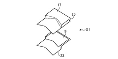
- FIG. 1A is an explanatory view illustrating a first forming step of a press forming method according to an embodiment of the present invention.
- FIG. 1B is an explanatory diagram illustrating a first molding step of the press molding method according to one embodiment of the present invention.
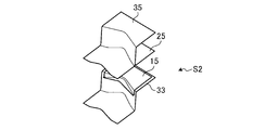
- FIG. 1C is an explanatory diagram illustrating a second molding step of the press molding method according to one embodiment of the present invention.
- FIG. 1D is an explanatory view illustrating a second forming step of the press forming method according to the embodiment of the present invention.
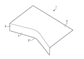
- FIG. 2 is an explanatory view of a molded part molded by the press molding method according to one embodiment of the present invention.
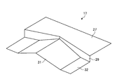
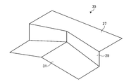
- FIG. 3 is an explanatory diagram of an intermediate-shaped part molded by the first molding step of the press molding method according to one embodiment of the present invention.
- FIG. 4A is an explanatory diagram of the first punch used in the first molding step of the press molding method according to one embodiment of the present invention.
- Drawing 4B is an explanatory view of the 1st punch used for the 1st forming process of the press forming method concerning one embodiment of the present invention.
- FIG. 5 is an explanatory diagram for explaining a mechanism of generation of shear strain (plastic strain generated by shear force) generated in the first molding step of the press molding method according to the embodiment of the present invention.
- shear strain plastic strain generated by shear force
- FIG. 6 is a contour diagram showing the plastic strain caused by the shearing force in the first molding step of the press molding method according to one embodiment of the present invention.
- FIG. 7 is a contour diagram showing the plate thickness reduction rate in the first forming step of the press forming method according to the embodiment of the present invention.
- FIG. 8A is an explanatory diagram of a second punch used in the second molding step of the press molding method according to one embodiment of the present invention.
- Drawing 8B is an explanatory view of the 2nd punch used for the 2nd forming process of the press forming method concerning one embodiment of the present invention.
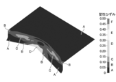
- FIG. 9 is a contour diagram showing the plastic strain caused by the shearing force in the second molding step of the press molding method according to one embodiment of the present invention.
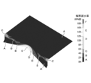
- FIG. 10 is a diagram showing the plate thickness reduction rate in the second forming step of the press forming method according to the embodiment of the present invention in a contour diagram.
- FIG. 11 is a diagram showing the plastic strain generated by the conventional press forming method in a contour diagram.
- FIG. 12 is a diagram showing the plate thickness reduction rate in the case of forming by a conventional press forming method in a contour diagram.
- FIG. 13 is an explanatory view of a molded part in the embodiment of the present invention.
- FIG. 14 is an explanatory diagram of the first punch in the embodiment of the present invention.
- FIG. 15 is an explanatory diagram of the second punch in the embodiment of the present invention.
- FIG. 16 is a graph for explaining the effect of the embodiment of the present invention.
- FIG. 17 is a graph for explaining the effect of the embodiment of the present invention.
- FIG. 18 is an explanatory diagram for explaining the effect of the embodiment of the present invention, and is a diagram showing a stress distribution in a molded part in a contour diagram.
- FIG. 19 is an explanatory view of another aspect of the first punch used in the first forming step in the press forming method of the present invention.
- FIG. 20 is an explanatory view of another aspect of the first punch used in the first forming step in the press forming method of the present invention.
- FIG. 21A is an explanatory view illustrating the mechanism of the press molding method according to the present invention.
- FIG. 21B is an explanatory view illustrating the mechanism of the press molding method according to the present invention.
- FIG. 22 is an explanatory view illustrating the mechanism of the press molding method according to the present invention.
- FIG. 23A is an explanatory view illustrating the mechanism of the press molding method according to the present invention.
- FIG. 23B is an explanatory view illustrating the mechanism of the press molding method according to the present invention.
- FIG. 24 is an explanatory view for explaining the mechanism of the press molding method according to the present invention.
- FIG. 25 is an explanatory view for explaining the mechanism of the press molding method according to the present invention.
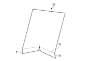
- FIG. 21A is a diagram showing a flat first blank 50.
- a broken line shows the 1st bending line 53 for shape
- FIG. 21B shows the portion of the first notch 55 in the first flange portion 51. open. Therefore, when the plate is connected to the plate without the first notch 55, the first flange portion 51 is stretched at a portion indicated by hatching in FIG. This is stretch flange molding.
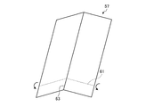
- FIG. 23A is a diagram showing a second blank 57 in which a rectangular plate is chevron shaped at the center.
- a broken line shows the 2nd bending line 61 for shape
- a part of the blank is formed at the center of the second flange portion 59 as shown in FIG. 23B.
- Overlap Therefore, in the case where the plate is connected without the second notch 63 in the plate, in the second flange portion 59, a shrinkage occurs in a portion indicated by hatching in FIG. 24, and the shrinkage is not absorbed by the increase in the plate thickness. Wrinkles occur. This is shrinkage flange forming.
- the flat first blank 50 is bent along the concave first fold line 53 in which a part of the outer edge is recessed inward.
- first flange portion 51 is molded, elongation occurs at the bent end portion of the first flange portion 51.
- FIG. 24 when the second blank 57 having a chevron shape is bent along a fold line 61 along the chevron and the second flange portion 59 is formed, the bent end of the second flange portion 59 is formed. Shrinkage occurs in the part.
- the flange portion is a fold line having two qualities, a first fold line 53 that is a concave shape that is recessed inward as shown in FIG. 22, and a second fold line 61 that is along a mountain shape shown in FIG. 24. It is only necessary to be bent along the shape.
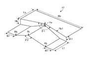
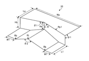
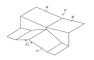
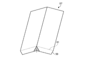
- FIG. 25 is a diagram showing an example of such an intermediate shape.
- the intermediate shape 65 is a shape including a top plate portion 69, a vertical wall portion and a mountain portion 73.
- the top plate 69 has a concave outer peripheral edge 67 in which a part of the outer peripheral edge is recessed inward.
- the vertical wall portion 71 is bent along the concave outer peripheral edge 67 of the top plate portion 69 and becomes a part of the flange portion.
- the chevron 73 is bent outward from the vertical wall 71 and is convex toward the top plate 69.
- the third fold line 75 formed on the vertical wall portion 71 is a fold line having the two characteristics described above. That is, since the intermediate shape 65 is recessed inward when viewed from above, the third fold line 75 has the same shape as the first fold line 53 of FIG. Further, since the intermediate shape 65 has a mountain shape when viewed from the front, the third fold line 75 has the same shape as the second fold line 61 of FIG.
- the press molding method according to an embodiment of the present invention is a press molding method for press molding the molded part 1 shown in FIG.
- the molded part 1 includes a top plate part 5 having a concave outer peripheral edge 3 in which a part of the outer peripheral edge is recessed inward, and a flange part 7 bent and formed along the concave outer peripheral edge 3 of the top plate part 5.
- the press molding method of the present embodiment includes a first molding step S1 and a second molding step S2.
- first forming step S1 as shown in FIG. 1A, a vertical wall portion 11 that is a part of the flange portion 7 and a portion outward from the vertical wall portion 11 at a portion where the flange portion 7 is formed in the blank material 9.
- An intermediate-shaped part 15 (see FIGS. 1B and 3) including a chevron 13 that is bent upward and convex upward is formed.
- the second punch 35 along the shape including the mountain-shaped portion 13 of the intermediate shape component 15 molded in the first molding step S1 vertically extends the portion including the mountain-shaped portion 13.
- the flange portion 7 is formed by bending along a boundary line 19 with the wall portion 11 (see FIG. 1D).
- the molded part 1, the first molding step S1, and the second molding step S2 that are target shapes of the press molding method of the present embodiment will be described in detail.
- a molded part 1 which is a target shape of press molding in the present embodiment includes a top plate portion 5 having a concave outer peripheral edge 3 in which a part of the outer peripheral edge is recessed inward, and the top plate. And a flange portion 7 formed by bending along the concave outer peripheral edge 3 of the portion 5.
- the elongation concentrates on the bent end portion 21 of the flange portion 7, and a crack is likely to occur in the portion.
- the first molding step S1 of the present embodiment is a step in which the intermediate shape part 15 (see FIG. 3) is molded.
- the intermediate-shaped component 15 includes a vertical wall portion 11 that is a part of the flange portion 7 at a portion where the flange portion 7 of the blank material 9 is formed, and is bent outward from the vertical wall and is A chevron portion 13 that protrudes toward the plate portion 5 side is included.
- a first die 23 serving as a lower die, a first punch 17 descending from above the die, and a blank 9 A pad 25 is used to hold the pad.
- the first punch 17 includes a flat portion 27, a vertical wall forming portion 29, and a mountain forming portion 31.
- the flat portion 27 is located at a portion corresponding to the top plate portion 5 of the molded part 1.
- the vertical wall forming part 29 forms the vertical wall part 11 extending downward along the concave outer peripheral edge 3 of the intermediate shaped part 15.
- the mountain forming portion 31 forms a mountain shape extending in the horizontal direction from the vertical wall forming portion 29 and projecting upward.
- the mountain-shaped portion 31 may have a mountain-shaped hem flat portion 32.
- the first die 23 has a shape corresponding to the shape of each molding part of the first punch 17. It is desirable that the pressing force with which the pad 25 presses the blank material 9 against the first die 23 is a sufficiently strong pressure so that the top plate portion 5 is not deformed during molding by the lowering of the first punch 17.
- the first molding step S1 will be described more specifically.
- the first punch 17 is lowered toward the first die 23 in a state where the blank material 9 is sandwiched between the first die 23 and the pad 25.
- both ends of the mountain forming portion 31 (see FIG. 4) of the first punch 17 abut against the blank material 9.
- the first punch 17 is further lowered, the chevron 13 and the vertical wall 11 are simultaneously formed in order from the bottom of the blank 9.
- FIG. 6 is a contour map showing a plastic strain generated by the shearing force in the first molding step S1.
- the part indicated by the symbol A is a part where the plastic strain is zero, and the plastic strain increases in the order of BCDEF.
- FIG. 7 is a contour diagram showing a change in plate thickness after the first forming step S1 is performed.
- the part indicated by the symbol A is a part where the plate thickness reduction rate is zero, and the plate thickness reduction ratio increases in the order of BCDEF. As shown in FIG. 7, the thickness reduction rate was 16% even near the top of the largest chevron 13.
- the chevron 13 is formed without the plastic strain being concentrated, and the boundary line 19 with the chevron 13 is formed on the vertical wall 11 (see FIG. 3).
- This boundary line 19 has the same property as the third fold line 75 shown in FIG. 25, that is, the property of causing the bent end portion 21 of the flange portion 7 to expand and contract at that time.
- sheared strain plastic strain generated by shearing force
- the top plate portion 5 No stress is generated. Therefore, the shape accuracy of the flatness of the top plate part 5 is kept high.
- ⁇ Second molding step> In the second forming step S2, as shown in FIG. 1C, the second die 33 and the pad 25 sandwich the intermediate-shaped part 15 formed in the first forming step S1 and follow the shape including the chevron portion 13. The punch 35 bends the portion including the chevron portion 13 downward along the boundary line 19 to form the flange portion 7.
- the second punch 35 used in the second molding step S2 has a concave shape along the mountain-shaped portion 13 and a shape along the vertical wall portion 11 molded in the first molding step S1. ing.
- the second punch 35 is different from the first punch 17 only in that the length of the vertical wall forming portion 29 is long.
- the second die 33 has a shape corresponding to the shape of each molding part of the second punch 35.
- the second punch 35 When the second punch 35 as shown in FIG. 8A descends along the vertical wall portion 11 formed in the first forming step S1, the second punch 35 comes into contact with the shape including the chevron portion 13. When the second punch 35 is further lowered, the shape including the chevron portion 13 is bent downward vertically from the boundary line 19 with the vertical wall portion 11, and the target shape is formed as shown in FIG. 1D. Note that, as shown in FIG. 8B, the second punch 35 may have a chevron hem flat portion 32. Further, any combination of the second punch 35 shown in FIG. 8A or 8B and the first punch 17 shown in FIG. 4A or 4B may be used.
- the shape including the chevron 13 molded in the first molding step S1 is bent along the boundary line 19 downward. At this time, both expansion and contraction act on the lower end of the center of the flange portion 7 and cancel each other. Therefore, the bending does not cause a large elongation, and no cracks occur.
- FIG. 9 is a contour diagram showing the distribution of plastic strain after the second forming step S2. As shown in FIG. 9, it can be seen that the plastic strain is dispersed over a wide range. That is, the occurrence of cracks is prevented by dispersing the plastic strain without concentrating. As shown in the contour diagram of FIG. 9, even when the method of the present invention is used, the plastic strain is generated at the bent end portion of the flange portion 7 because the elongation and shrinkage occurring in the portion are not completely the same. Because there is no.
- FIG. 10 is a contour diagram showing the distribution of the plate thickness after the second forming step S2. As shown in FIG. 10, the change in the plate thickness is dispersed over a wide range, and the plate thickness reduction rate is 20% even at the portion where the plate thickness reduction rate is the largest. This means that the maximum value of the plate thickness reduction rate is reduced by the canceling action between elongation and shrinkage, and cracks are reliably prevented.
- FIG. 11 is a contour diagram showing a plastic strain distribution when press-molding is performed by a conventional press-molding method in which stretch flange molding is performed in one step.
- FIG. 12 is a contour diagram showing the distribution of the plate thickness when press-molding is performed by a conventional press-molding method in which stretch flange molding is performed in one step. Comparing FIG. 11 with FIG. 9, in the conventional method (FIG. 11), the portion where the plastic strain is generated does not disperse as in FIG. You can see that they are concentrated. Further, comparing FIG. 12 with FIG. 10, in the conventional method (FIG. 12), the portion where the plate thickness change occurs is not dispersed over a wide range of the flange portion 7 as in FIG. You can see that they are focused on.
- the maximum thickness reduction rate in the conventional method shown in FIG. 12 is 41%, which is larger than 20% in the present invention shown in FIG.
- the intermediate-shaped component 15 including the chevron 13 that is bent outward from the top and convex toward the top plate 5 is formed.
- a portion including the chevron portion 13 of the intermediate shape part 15 molded in the first molding step S1 is bent along the boundary line 19 with the vertical wall portion 11 to obtain the final shape.
- the flange part 7 of the molded part 1 is molded.
- the first formation step S1 plastic distortion occurs in the wide range of the flange portion 7 in the molded part 1 to form the mountain portion 13, thereby preventing the concentration of elongation and at the bent end portion of the flange portion 7.
- the required elongation deformation is preformed.
- the second molding step S2 bending is mainly performed, and elongation and shrinkage occur simultaneously at the bent end portion of the flange portion 7 and elongation does not concentrate. It can be performed.
- the plastic strain at the time of forming the chevron portion 13 in the first molding step S1 occurs between the vertical wall portion 11 and the chevron portion 13 serving as the flange portion 7, almost no stress is generated in the top plate portion 5.
- the top plate portion 5 is also excellent in shape accuracy (the top plate portion 5 is hardly deformed).
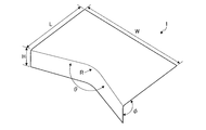
- FIG. 13 is a diagram showing the shape of a target molded part.
- Table 1 is a table showing dimensions and the like of each part of the molded part shown in FIG.
- the units of W, L, H, and R are mm, and the units of ⁇ and ⁇ are degrees.
- FIG. 14 is a diagram showing the first punch used in the first molding step of the present invention.
- FIG. 15 is a view showing the second punch used in the second molding step.
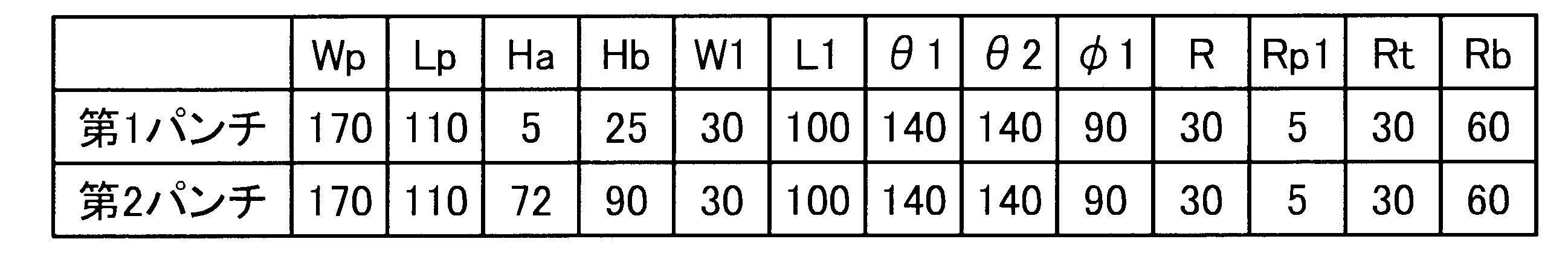
- Table 2 is a table showing dimensions of each part shown in FIGS.
- the units of Wp, Lp, Ha, Hb, W1, L1, R, Rp1, Rt, and Rb are mm, and the units of ⁇ 1, ⁇ 2, and ⁇ 1 are degrees.
- R, Rp1, Rt, and Rb indicate the radius of the round processed portion.
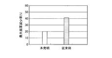
- FIG. 16 compares the maximum sheet thickness reduction rate when the height H of the vertical wall portion of the flange portion is 30 mm between the present invention and the conventional example (conventional press forming method in which stretch flange forming is performed in one step). It is a graph display.
- FIG. 17 is a graph showing the maximum plate thickness reduction rate when the height H of the vertical wall portion of the flange portion is 40 mm in comparison with the present invention and the conventional example. As shown in FIG. 16, when the height H of the vertical wall portion is 30 mm, the maximum thickness reduction rate in the conventional example was 41%, whereas the maximum thickness reduction rate of the present invention was 20%. Met. Further, as shown in FIG.
- the maximum thickness reduction rate in the conventional example was 58%, whereas the maximum thickness reduction rate of the present invention is It was 31%.
- the press molding method of the present invention it has been demonstrated that the maximum thickness reduction rate is reduced as compared with the conventional method. This means that the occurrence of cracks is effectively prevented by stretch flange molding by the press molding method of the present invention.
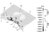
- FIG. 18 is a contour diagram showing the stress distribution of the blank before die release after the second molding step of the present invention.
- a portion where the stress is zero is indicated by a symbol A, and is indicated by ⁇ B,. , + C.
- FIG. 18 it can be seen that almost no stress is generated in the top plate portion 5, and there is almost no deformation of the top plate portion 5 even after release. This is presumed to be because only the flange portion 7 causes plastic strain in both the first molding step S1 and the second molding step S2. For this reason, it was proved that the press molding method of the present invention is extremely useful even when the accuracy of the shape of the top plate portion 5 is required.
- the top-plate part 5 was flat as a molded component shape
- molded by the press molding method of this invention does not need to be flat.
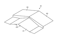
- the concave portion having an inclined surface in which the top plate portion is inclined downward toward the center may be used, or conversely, the convex shape having the inclined surface in which the top plate portion is inclined upward toward the center. It may be a thing.
- the top plate forming portion 39 of the first punch 37 in the case where the top plate portion has a concave shape is a concave shape made of an inclined surface inclined downward toward the center.
- the inclination angle ⁇ 3 is desirably larger than the inclination angle ⁇ 2 when the top plate portion is flat.
- the top plate forming portion 43 of the first punch 41 in the case where the top plate portion has a convex shape, as shown in FIG. 20, is a convex shape composed of an inclined surface that is inclined upward toward the center, and a mountain forming portion
- the inclination angle ⁇ 4 of 31 is preferably smaller than the inclination angle ⁇ 2 when the top plate portion is flat.
- the present invention can be applied to a process of forming a flange by pressing a metal plate. As a result, it is possible to fundamentally solve the problem of stretch flange cracks without reducing the degree of freedom of the product shape, and furthermore, it is possible to perform a press molding process with excellent accuracy with respect to the shape of the top plate portion.
Landscapes
- Engineering & Computer Science (AREA)
- Mechanical Engineering (AREA)
- Shaping Metal By Deep-Drawing, Or The Like (AREA)
Abstract
Description
本実施の形態におけるプレス成形の目標形状である成形部品1は、図2に示すように、外周縁の一部が内方に凹んだ凹状外周縁3を有する天板部5と、該天板部5における前記凹状外周縁3に沿って曲げ成形されたフランジ部7とを有する。このような形状の成形部品1では、フランジ部7における屈曲端部21に伸びが集中して、当該部位に割れが発生しやすい。
本実施の形態の第1成形工程S1は、中間形状部品15(図3参照)が成形される工程である。中間形状部品15には、ブランク材9におけるフランジ部7が形成される部位に、フランジ部7の一部となる縦壁部11と、該縦壁から外方に向けて折り曲げられると共に上方すなわち天板部5側に凸となる山形部13とが含まれる。
第2成形工程S2では、図1Cに示すように、第2ダイ33とパッド25とが、第1成形工程S1で成形された中間形状部品15を挟み、山形部13を含む形状に沿う第2パンチ35が、山形部13を含む部位を境界線19に沿って下方に折り曲げてフランジ部7を成形する。
本発明の効果を検証するため、従来方法と本発明の方法とが有限要素法による解析で検証された。解析に用いたソフトウエアはLSTC社製のLS-DYNAバージョン971であり、動的陽解法(dynamic explicit method)が用いられた。図13は、対象とする成形部品の形状を示した図である。また、表1は、図13に示した成形部品の各部の寸法等を示す表である。成形部品の形状は、フランジ部の縦壁部の高さHが30mmのもの(成形部品形状1)と、縦壁部の高さHが40mmのもの(成形部品形状2)との2種類とした。なお、表1において、W、L、H、Rの単位はmmであり、θ、φの単位はdegree(度)である。

S2 第2成形工程
1 成形部品
3 凹状外周縁
5 天板部
7 フランジ部
9 ブランク材
11 縦壁部
13 山形部
15 中間形状部品
17 第1パンチ
19 境界線
21 屈曲端部(フランジ中央下端部)
23 第1ダイ
25 パッド
27 平坦部
29 縦壁成形部
31 山形成形部
32 山形裾平坦部
33 第2ダイ
35 第2パンチ
37 第1パンチ
39 天板成形部
41 第1パンチ
43 天板成形部
50 第1ブランク
51 第1フランジ部
53 第1折り曲げ線
55 第1切り込み
57 第2ブランク
59 第2フランジ部
61 第2折り曲げ線
63 第2切り込み
65 中間形状
67 凹状外周縁
69 天板部
71 縦壁部
73 山形部
75 第3折り曲げ線
Claims (2)
- 外周縁の一部が内方に凹んだ凹状外周縁を有する天板部と、該天板部における凹状外周縁に沿って曲げ成形されたフランジ部を有する成形部品をプレス成形するプレス成形方法であって、
ブランク材における前記フランジ部が形成される部位に、フランジ部の一部となる縦壁部と、該縦壁部から外方に向けて折り曲げられると共に前記天板部側に凸となる山形部を含む中間形状部品を成形する第1成形工程と、
該第1成形工程で成形された中間形状部品の前記山形部を含む部位を縦壁部との境界となる折り曲げ線に沿って曲げ成形してフランジ部を成形する第2成形工程と、を含むプレス成形方法。 - 前記第1成形工程は、ブランク材における天板部となる部位をパッドと第1ダイで挟持して、前記ブランク材におけるフランジ部となる部位を第1パンチによって成形し、
前記第2成形工程は、中間形状部品における天板部となる部位をパッドと第2ダイで挟持して、前記中間形状部品における山形部を含む形状に沿う第2パンチによって成形する請求項1記載のプレス成形方法。
Priority Applications (4)
| Application Number | Priority Date | Filing Date | Title |
|---|---|---|---|
| CN201380065074.7A CN104870117B (zh) | 2012-12-17 | 2013-10-28 | 冲压成型方法 |
| EP13865147.6A EP2933034B1 (en) | 2012-12-17 | 2013-10-28 | Press forming method |
| KR1020157013909A KR101652877B1 (ko) | 2012-12-17 | 2013-10-28 | 프레스 성형 방법 |
| US14/443,744 US9937546B2 (en) | 2012-12-17 | 2013-10-28 | Press forming method |
Applications Claiming Priority (2)
| Application Number | Priority Date | Filing Date | Title |
|---|---|---|---|
| JP2012274398A JP5510533B1 (ja) | 2012-12-17 | 2012-12-17 | プレス成形方法 |
| JP2012-274398 | 2012-12-17 |
Publications (1)
| Publication Number | Publication Date |
|---|---|
| WO2014097745A1 true WO2014097745A1 (ja) | 2014-06-26 |
Family
ID=50978092
Family Applications (1)
| Application Number | Title | Priority Date | Filing Date |
|---|---|---|---|
| PCT/JP2013/079132 Ceased WO2014097745A1 (ja) | 2012-12-17 | 2013-10-28 | プレス成形方法 |
Country Status (6)
| Country | Link |
|---|---|
| US (1) | US9937546B2 (ja) |
| EP (1) | EP2933034B1 (ja) |
| JP (1) | JP5510533B1 (ja) |
| KR (1) | KR101652877B1 (ja) |
| CN (1) | CN104870117B (ja) |
| WO (1) | WO2014097745A1 (ja) |
Cited By (1)
| Publication number | Priority date | Publication date | Assignee | Title |
|---|---|---|---|---|
| JP7396415B1 (ja) | 2022-09-05 | 2023-12-12 | Jfeスチール株式会社 | プレス成形品の製造方法 |
Families Citing this family (13)
| Publication number | Priority date | Publication date | Assignee | Title |
|---|---|---|---|---|
| JP5569609B1 (ja) * | 2013-02-28 | 2014-08-13 | Jfeスチール株式会社 | プレス成形方法 |
| JP5983585B2 (ja) * | 2013-11-26 | 2016-08-31 | Jfeスチール株式会社 | プレス成形方法 |
| CA2977041A1 (en) | 2015-03-27 | 2016-10-06 | Nippon Steel & Sumitomo Metal Corporation | Computer implemented blank manufacturing method and press forming method |
| WO2017006793A1 (ja) * | 2015-07-06 | 2017-01-12 | 新日鐵住金株式会社 | プレス部品の製造方法および製造装置 |
| MX2018015863A (es) * | 2016-06-27 | 2019-06-17 | Nippon Steel & Sumitomo Metal Corp | Metodo y aparato para producir un componente formado por prensado. |
| JP6479254B2 (ja) * | 2016-09-12 | 2019-03-06 | 古河電気工業株式会社 | 銅箔およびこれを有する銅張積層板 |
| US11247256B2 (en) | 2017-06-28 | 2022-02-15 | Takashi Iiduka | Method for cutting metal plate, method for manufacturing metal product, and metal product |
| JP7070287B2 (ja) * | 2018-09-25 | 2022-05-18 | 日本製鉄株式会社 | プレス成形部品の製造方法、及びプレス成形部品 |
| JP6908078B2 (ja) * | 2018-10-31 | 2021-07-21 | Jfeスチール株式会社 | プレス部品の製造方法及び下金型の設計方法 |
| WO2020153500A1 (ja) * | 2019-01-25 | 2020-07-30 | 日本製鉄株式会社 | プレス成形方法およびプレス装置 |
| JP6683269B1 (ja) * | 2019-02-01 | 2020-04-15 | Jfeスチール株式会社 | スプリングバック量変動要因部位特定方法 |
| WO2021125293A1 (ja) * | 2019-12-18 | 2021-06-24 | 日本製鉄株式会社 | プレス成形品の製造方法およびプレス成形装置、プレス成形ライン |
| WO2026067979A1 (en) * | 2024-09-26 | 2026-04-02 | DeepForm Limited | Forming of sheet metal |
Citations (8)
| Publication number | Priority date | Publication date | Assignee | Title |
|---|---|---|---|---|
| JPS5893322U (ja) * | 1981-12-15 | 1983-06-24 | マツダ株式会社 | フランジ加工装置 |
| JPH0569049A (ja) * | 1991-09-13 | 1993-03-23 | Honda Motor Co Ltd | 伸びフランジ曲げ加工方法及び曲げ加工装置 |
| JP2008119736A (ja) | 2006-11-14 | 2008-05-29 | Kobe Steel Ltd | プレス成形金型装置およびプレス成形方法 |
| JP2009160655A (ja) | 2007-12-11 | 2009-07-23 | Kobe Steel Ltd | フランジ付き成形部材のプレス成形方法 |
| JP2009214118A (ja) | 2008-03-07 | 2009-09-24 | Nippon Steel Corp | プレス成形方法およびプレス成形用素板 |
| JP2009241109A (ja) * | 2008-03-31 | 2009-10-22 | Kobe Steel Ltd | チャンネル部材の曲げ成形方法 |
| JP2009255167A (ja) | 2008-03-24 | 2009-11-05 | Nippon Steel Corp | 面取りダイを用いた打ち抜き加工方法及び装置 |
| WO2012070623A1 (ja) * | 2010-11-24 | 2012-05-31 | 新日本製鐵株式会社 | L形製品の製造方法 |
Family Cites Families (6)
| Publication number | Priority date | Publication date | Assignee | Title |
|---|---|---|---|---|
| US2235090A (en) * | 1939-01-26 | 1941-03-18 | Westinghouse Electric & Mfg Co | Method of forming range platform and back splasher structures |
| FR2655892A1 (fr) * | 1989-12-18 | 1991-06-21 | Lorraine Laminage | Procede et dispositif de mise en forme d'un flan de tole notamment pour realiser un masque de tube cathodique et masque de tube cathodique obtenu selon ce procede. |
| JP4908763B2 (ja) * | 2005-02-04 | 2012-04-04 | 本田技研工業株式会社 | 塗装鋼板の成形方法 |
| JP5145689B2 (ja) * | 2006-10-30 | 2013-02-20 | 新日鐵住金株式会社 | ハット型金属製部品のプレス成形用ブランク |
| DE102010016960A1 (de) * | 2010-05-14 | 2011-11-17 | Thyssenkrupp Steel Europe Ag | Verfahren zur Herstellung von Hohlprofilen mit einem Längsflansch |
| JP5807293B2 (ja) * | 2010-08-27 | 2015-11-10 | 株式会社エフ・シー・シー | アンダーカット部の成形方法およびアンダーカット部を有する成形品の製造方法 |
-
2012
- 2012-12-17 JP JP2012274398A patent/JP5510533B1/ja active Active
-
2013
- 2013-10-28 US US14/443,744 patent/US9937546B2/en active Active
- 2013-10-28 EP EP13865147.6A patent/EP2933034B1/en active Active
- 2013-10-28 CN CN201380065074.7A patent/CN104870117B/zh active Active
- 2013-10-28 KR KR1020157013909A patent/KR101652877B1/ko active Active
- 2013-10-28 WO PCT/JP2013/079132 patent/WO2014097745A1/ja not_active Ceased
Patent Citations (8)
| Publication number | Priority date | Publication date | Assignee | Title |
|---|---|---|---|---|
| JPS5893322U (ja) * | 1981-12-15 | 1983-06-24 | マツダ株式会社 | フランジ加工装置 |
| JPH0569049A (ja) * | 1991-09-13 | 1993-03-23 | Honda Motor Co Ltd | 伸びフランジ曲げ加工方法及び曲げ加工装置 |
| JP2008119736A (ja) | 2006-11-14 | 2008-05-29 | Kobe Steel Ltd | プレス成形金型装置およびプレス成形方法 |
| JP2009160655A (ja) | 2007-12-11 | 2009-07-23 | Kobe Steel Ltd | フランジ付き成形部材のプレス成形方法 |
| JP2009214118A (ja) | 2008-03-07 | 2009-09-24 | Nippon Steel Corp | プレス成形方法およびプレス成形用素板 |
| JP2009255167A (ja) | 2008-03-24 | 2009-11-05 | Nippon Steel Corp | 面取りダイを用いた打ち抜き加工方法及び装置 |
| JP2009241109A (ja) * | 2008-03-31 | 2009-10-22 | Kobe Steel Ltd | チャンネル部材の曲げ成形方法 |
| WO2012070623A1 (ja) * | 2010-11-24 | 2012-05-31 | 新日本製鐵株式会社 | L形製品の製造方法 |
Non-Patent Citations (4)
| Title |
|---|
| "Third Edition of Press Forming Difficulty Handbook", 30 March 2007, NIKKAN KOGYO SHIMBUN, LTD., pages: 234 |
| CURRENT ADVANCES IN MATERIALS AND PROCESSES, vol. 21, 2008, pages 321 |
| JOURNAL OF THE JAPAN SOCIETY FOR TECHNOLOGY OF PLASTICITY, vol. 52, no. 604, 2011, pages 569 - 573 |
| See also references of EP2933034A4 * |
Cited By (4)
| Publication number | Priority date | Publication date | Assignee | Title |
|---|---|---|---|---|
| JP7396415B1 (ja) | 2022-09-05 | 2023-12-12 | Jfeスチール株式会社 | プレス成形品の製造方法 |
| WO2024053186A1 (ja) | 2022-09-05 | 2024-03-14 | Jfeスチール株式会社 | プレス成形品の製造方法 |
| JP2024035883A (ja) * | 2022-09-05 | 2024-03-15 | Jfeスチール株式会社 | プレス成形品の製造方法 |
| KR20250041011A (ko) | 2022-09-05 | 2025-03-25 | 제이에프이 스틸 가부시키가이샤 | 프레스 성형품의 제조 방법 |
Also Published As
| Publication number | Publication date |
|---|---|
| JP5510533B1 (ja) | 2014-06-04 |
| CN104870117A (zh) | 2015-08-26 |
| EP2933034A4 (en) | 2015-12-16 |
| US9937546B2 (en) | 2018-04-10 |
| EP2933034B1 (en) | 2016-06-29 |
| KR101652877B1 (ko) | 2016-08-31 |
| EP2933034A1 (en) | 2015-10-21 |
| US20150298193A1 (en) | 2015-10-22 |
| JP2014117728A (ja) | 2014-06-30 |
| CN104870117B (zh) | 2016-08-24 |
| KR20150080572A (ko) | 2015-07-09 |
Similar Documents
| Publication | Publication Date | Title |
|---|---|---|
| JP5510533B1 (ja) | プレス成形方法 | |
| JP5569609B1 (ja) | プレス成形方法 | |
| US11731185B2 (en) | Method for manufacturing pressed component | |
| JP5114688B2 (ja) | 形状凍結性に優れた金属部材の成形方法 | |
| CN107708884B (zh) | 拉伸凸缘成型部件的制造方法 | |
| JP2011206789A (ja) | プレス成形方法 | |
| US20210260640A1 (en) | Method for designing mold shape and method for producing pressed part | |
| WO2016194503A1 (ja) | プレス成形方法及びプレス成形金型 | |
| CN115666809A (zh) | 冲压成形方法 | |
| CN113365752B (zh) | 冲压部件的制造方法以及坯料的制造方法 | |
| CN107921504A (zh) | 拉伸凸缘成形零件的制造方法 | |
| CN113727791A (zh) | 冲压成型方法 | |
| JP2016104492A (ja) | プレス成形方法 | |
| WO2015079794A1 (ja) | プレス成形方法 | |
| WO2021010352A1 (ja) | ブランク材の製造方法、プレス成形品の製造方法、形状判定方法、形状判定プログラム、ブランク材の製造装置、及びブランク材 | |
| CN109475916B (zh) | 冲压件制造方法 | |
| JP2012115868A (ja) | プレス板曲げ加工方法 | |
| US12233445B2 (en) | Press forming method | |
| JP2020049494A (ja) | プレス成形部品の製造方法、及びプレス成形部品 | |
| WO2015079791A1 (ja) | プレス成形方法 | |
| JP6119716B2 (ja) | プレス成形方法及びプレス成形用金型 |
Legal Events
| Date | Code | Title | Description |
|---|---|---|---|
| 121 | Ep: the epo has been informed by wipo that ep was designated in this application |
Ref document number: 13865147 Country of ref document: EP Kind code of ref document: A1 |
|
| WWE | Wipo information: entry into national phase |
Ref document number: 14443744 Country of ref document: US |
|
| ENP | Entry into the national phase |
Ref document number: 20157013909 Country of ref document: KR Kind code of ref document: A |
|
| WWE | Wipo information: entry into national phase |
Ref document number: IDP00201503585 Country of ref document: ID Ref document number: 2013865147 Country of ref document: EP |
|
| NENP | Non-entry into the national phase |
Ref country code: DE |