WO2014097831A1 - 冷媒循環装置 - Google Patents
冷媒循環装置 Download PDFInfo
- Publication number
- WO2014097831A1 WO2014097831A1 PCT/JP2013/081760 JP2013081760W WO2014097831A1 WO 2014097831 A1 WO2014097831 A1 WO 2014097831A1 JP 2013081760 W JP2013081760 W JP 2013081760W WO 2014097831 A1 WO2014097831 A1 WO 2014097831A1
- Authority
- WO
- WIPO (PCT)
- Prior art keywords
- electric compressor
- vehicle
- refrigerant
- temperature
- pressure
- Prior art date
- Legal status (The legal status is an assumption and is not a legal conclusion. Google has not performed a legal analysis and makes no representation as to the accuracy of the status listed.)
- Ceased
Links
Images

Classifications
-
- B—PERFORMING OPERATIONS; TRANSPORTING
- B60—VEHICLES IN GENERAL
- B60L—PROPULSION OF ELECTRICALLY-PROPELLED VEHICLES; SUPPLYING ELECTRIC POWER FOR AUXILIARY EQUIPMENT OF ELECTRICALLY-PROPELLED VEHICLES; ELECTRODYNAMIC BRAKE SYSTEMS FOR VEHICLES IN GENERAL; MAGNETIC SUSPENSION OR LEVITATION FOR VEHICLES; MONITORING OPERATING VARIABLES OF ELECTRICALLY-PROPELLED VEHICLES; ELECTRIC SAFETY DEVICES FOR ELECTRICALLY-PROPELLED VEHICLES
- B60L1/00—Supplying electric power to auxiliary equipment of vehicles
- B60L1/003—Supplying electric power to auxiliary equipment of vehicles to auxiliary motors, e.g. for pumps, compressors
-
- B—PERFORMING OPERATIONS; TRANSPORTING
- B60—VEHICLES IN GENERAL
- B60H—ARRANGEMENTS OF HEATING, COOLING, VENTILATING OR OTHER AIR-TREATING DEVICES SPECIALLY ADAPTED FOR PASSENGER OR GOODS SPACES OF VEHICLES
- B60H1/00—Heating, cooling or ventilating devices
- B60H1/32—Cooling devices
- B60H1/3204—Cooling devices using compression
- B60H1/3205—Control means therefor
- B60H1/3216—Control means therefor for improving a change in operation duty of a compressor in a vehicle
-
- B—PERFORMING OPERATIONS; TRANSPORTING
- B60—VEHICLES IN GENERAL
- B60H—ARRANGEMENTS OF HEATING, COOLING, VENTILATING OR OTHER AIR-TREATING DEVICES SPECIALLY ADAPTED FOR PASSENGER OR GOODS SPACES OF VEHICLES
- B60H1/00—Heating, cooling or ventilating devices
- B60H1/00271—HVAC devices specially adapted for particular vehicle parts or components and being connected to the vehicle HVAC unit
- B60H1/00278—HVAC devices specially adapted for particular vehicle parts or components and being connected to the vehicle HVAC unit for the battery
-
- B—PERFORMING OPERATIONS; TRANSPORTING
- B60—VEHICLES IN GENERAL
- B60H—ARRANGEMENTS OF HEATING, COOLING, VENTILATING OR OTHER AIR-TREATING DEVICES SPECIALLY ADAPTED FOR PASSENGER OR GOODS SPACES OF VEHICLES
- B60H1/00—Heating, cooling or ventilating devices
- B60H1/00357—Air-conditioning arrangements specially adapted for particular vehicles
- B60H1/00385—Air-conditioning arrangements specially adapted for particular vehicles for vehicles having an electrical drive, e.g. hybrid or fuel cell
-
- B—PERFORMING OPERATIONS; TRANSPORTING
- B60—VEHICLES IN GENERAL
- B60L—PROPULSION OF ELECTRICALLY-PROPELLED VEHICLES; SUPPLYING ELECTRIC POWER FOR AUXILIARY EQUIPMENT OF ELECTRICALLY-PROPELLED VEHICLES; ELECTRODYNAMIC BRAKE SYSTEMS FOR VEHICLES IN GENERAL; MAGNETIC SUSPENSION OR LEVITATION FOR VEHICLES; MONITORING OPERATING VARIABLES OF ELECTRICALLY-PROPELLED VEHICLES; ELECTRIC SAFETY DEVICES FOR ELECTRICALLY-PROPELLED VEHICLES
- B60L1/00—Supplying electric power to auxiliary equipment of vehicles
- B60L1/02—Supplying electric power to auxiliary equipment of vehicles to electric heating circuits
-
- B—PERFORMING OPERATIONS; TRANSPORTING
- B60—VEHICLES IN GENERAL
- B60L—PROPULSION OF ELECTRICALLY-PROPELLED VEHICLES; SUPPLYING ELECTRIC POWER FOR AUXILIARY EQUIPMENT OF ELECTRICALLY-PROPELLED VEHICLES; ELECTRODYNAMIC BRAKE SYSTEMS FOR VEHICLES IN GENERAL; MAGNETIC SUSPENSION OR LEVITATION FOR VEHICLES; MONITORING OPERATING VARIABLES OF ELECTRICALLY-PROPELLED VEHICLES; ELECTRIC SAFETY DEVICES FOR ELECTRICALLY-PROPELLED VEHICLES
- B60L58/00—Methods or circuit arrangements for monitoring or controlling batteries or fuel cells, specially adapted for electric vehicles
- B60L58/10—Methods or circuit arrangements for monitoring or controlling batteries or fuel cells, specially adapted for electric vehicles for monitoring or controlling batteries
- B60L58/24—Methods or circuit arrangements for monitoring or controlling batteries or fuel cells, specially adapted for electric vehicles for monitoring or controlling batteries for controlling the temperature of batteries
- B60L58/26—Methods or circuit arrangements for monitoring or controlling batteries or fuel cells, specially adapted for electric vehicles for monitoring or controlling batteries for controlling the temperature of batteries by cooling
-
- B—PERFORMING OPERATIONS; TRANSPORTING
- B60—VEHICLES IN GENERAL
- B60H—ARRANGEMENTS OF HEATING, COOLING, VENTILATING OR OTHER AIR-TREATING DEVICES SPECIALLY ADAPTED FOR PASSENGER OR GOODS SPACES OF VEHICLES
- B60H1/00—Heating, cooling or ventilating devices
- B60H1/00271—HVAC devices specially adapted for particular vehicle parts or components and being connected to the vehicle HVAC unit
- B60H2001/00307—Component temperature regulation using a liquid flow
-
- B—PERFORMING OPERATIONS; TRANSPORTING
- B60—VEHICLES IN GENERAL
- B60L—PROPULSION OF ELECTRICALLY-PROPELLED VEHICLES; SUPPLYING ELECTRIC POWER FOR AUXILIARY EQUIPMENT OF ELECTRICALLY-PROPELLED VEHICLES; ELECTRODYNAMIC BRAKE SYSTEMS FOR VEHICLES IN GENERAL; MAGNETIC SUSPENSION OR LEVITATION FOR VEHICLES; MONITORING OPERATING VARIABLES OF ELECTRICALLY-PROPELLED VEHICLES; ELECTRIC SAFETY DEVICES FOR ELECTRICALLY-PROPELLED VEHICLES
- B60L2240/00—Control parameters of input or output; Target parameters
- B60L2240/10—Vehicle control parameters
- B60L2240/34—Cabin temperature
-
- B—PERFORMING OPERATIONS; TRANSPORTING
- B60—VEHICLES IN GENERAL
- B60L—PROPULSION OF ELECTRICALLY-PROPELLED VEHICLES; SUPPLYING ELECTRIC POWER FOR AUXILIARY EQUIPMENT OF ELECTRICALLY-PROPELLED VEHICLES; ELECTRODYNAMIC BRAKE SYSTEMS FOR VEHICLES IN GENERAL; MAGNETIC SUSPENSION OR LEVITATION FOR VEHICLES; MONITORING OPERATING VARIABLES OF ELECTRICALLY-PROPELLED VEHICLES; ELECTRIC SAFETY DEVICES FOR ELECTRICALLY-PROPELLED VEHICLES
- B60L2240/00—Control parameters of input or output; Target parameters
- B60L2240/10—Vehicle control parameters
- B60L2240/36—Temperature of vehicle components or parts
-
- B—PERFORMING OPERATIONS; TRANSPORTING
- B60—VEHICLES IN GENERAL
- B60L—PROPULSION OF ELECTRICALLY-PROPELLED VEHICLES; SUPPLYING ELECTRIC POWER FOR AUXILIARY EQUIPMENT OF ELECTRICALLY-PROPELLED VEHICLES; ELECTRODYNAMIC BRAKE SYSTEMS FOR VEHICLES IN GENERAL; MAGNETIC SUSPENSION OR LEVITATION FOR VEHICLES; MONITORING OPERATING VARIABLES OF ELECTRICALLY-PROPELLED VEHICLES; ELECTRIC SAFETY DEVICES FOR ELECTRICALLY-PROPELLED VEHICLES
- B60L2240/00—Control parameters of input or output; Target parameters
- B60L2240/40—Drive Train control parameters
- B60L2240/54—Drive Train control parameters related to batteries
- B60L2240/545—Temperature
-
- F—MECHANICAL ENGINEERING; LIGHTING; HEATING; WEAPONS; BLASTING
- F25—REFRIGERATION OR COOLING; COMBINED HEATING AND REFRIGERATION SYSTEMS; HEAT PUMP SYSTEMS; MANUFACTURE OR STORAGE OF ICE; LIQUEFACTION SOLIDIFICATION OF GASES
- F25B—REFRIGERATION MACHINES, PLANTS OR SYSTEMS; COMBINED HEATING AND REFRIGERATION SYSTEMS; HEAT PUMP SYSTEMS
- F25B2600/00—Control issues
- F25B2600/25—Control of valves
- F25B2600/2513—Expansion valves
-
- F—MECHANICAL ENGINEERING; LIGHTING; HEATING; WEAPONS; BLASTING
- F25—REFRIGERATION OR COOLING; COMBINED HEATING AND REFRIGERATION SYSTEMS; HEAT PUMP SYSTEMS; MANUFACTURE OR STORAGE OF ICE; LIQUEFACTION SOLIDIFICATION OF GASES
- F25B—REFRIGERATION MACHINES, PLANTS OR SYSTEMS; COMBINED HEATING AND REFRIGERATION SYSTEMS; HEAT PUMP SYSTEMS
- F25B2700/00—Sensing or detecting of parameters; Sensors therefor
- F25B2700/19—Pressures
- F25B2700/193—Pressures of the compressor
- F25B2700/1931—Discharge pressures
-
- F—MECHANICAL ENGINEERING; LIGHTING; HEATING; WEAPONS; BLASTING
- F25—REFRIGERATION OR COOLING; COMBINED HEATING AND REFRIGERATION SYSTEMS; HEAT PUMP SYSTEMS; MANUFACTURE OR STORAGE OF ICE; LIQUEFACTION SOLIDIFICATION OF GASES
- F25B—REFRIGERATION MACHINES, PLANTS OR SYSTEMS; COMBINED HEATING AND REFRIGERATION SYSTEMS; HEAT PUMP SYSTEMS
- F25B2700/00—Sensing or detecting of parameters; Sensors therefor
- F25B2700/19—Pressures
- F25B2700/195—Pressures of the condenser
-
- F—MECHANICAL ENGINEERING; LIGHTING; HEATING; WEAPONS; BLASTING
- F25—REFRIGERATION OR COOLING; COMBINED HEATING AND REFRIGERATION SYSTEMS; HEAT PUMP SYSTEMS; MANUFACTURE OR STORAGE OF ICE; LIQUEFACTION SOLIDIFICATION OF GASES
- F25B—REFRIGERATION MACHINES, PLANTS OR SYSTEMS; COMBINED HEATING AND REFRIGERATION SYSTEMS; HEAT PUMP SYSTEMS
- F25B2700/00—Sensing or detecting of parameters; Sensors therefor
- F25B2700/21—Temperatures
- F25B2700/2115—Temperatures of a compressor or the drive means therefor
-
- Y—GENERAL TAGGING OF NEW TECHNOLOGICAL DEVELOPMENTS; GENERAL TAGGING OF CROSS-SECTIONAL TECHNOLOGIES SPANNING OVER SEVERAL SECTIONS OF THE IPC; TECHNICAL SUBJECTS COVERED BY FORMER USPC CROSS-REFERENCE ART COLLECTIONS [XRACs] AND DIGESTS
- Y02—TECHNOLOGIES OR APPLICATIONS FOR MITIGATION OR ADAPTATION AGAINST CLIMATE CHANGE
- Y02T—CLIMATE CHANGE MITIGATION TECHNOLOGIES RELATED TO TRANSPORTATION
- Y02T10/00—Road transport of goods or passengers
- Y02T10/60—Other road transportation technologies with climate change mitigation effect
- Y02T10/70—Energy storage systems for electromobility, e.g. batteries
Definitions
- the present invention relates to a heat protection technique for an electric compressor in a refrigerant circulation device mounted on a vehicle.
- An electric compressor is used for refrigerant compression in a vehicle air conditioner in a vehicle such as an electric vehicle and a hybrid vehicle that have been developed in recent years, in which an engine is not mounted or the engine is not operated during traveling. It has been.
- electric vehicles and hybrid vehicles are equipped with a high-voltage battery for driving driving, and in order to maintain the temperature of the vehicle battery at an appropriate temperature, the vehicle air conditioner is used to There has also been proposed a vehicle configured to adjust the temperature.
- an evaporator for cooling an in-vehicle battery is provided in the refrigerant circulation path in addition to the evaporator for the in-vehicle battery, and both the evaporator for the in-vehicle battery and the evaporator for cooling the in-vehicle battery are provided by the same compressor. It is configured to supply a compressed refrigerant.
- a technique for adjusting the temperature of equipment mounted on a vehicle by using a part of a heat medium used in an air conditioner for a vehicle interior has been conventionally known.
- Patent Document 1 engine cooling water is used in an in-vehicle heating device, and a part of this cooling water is used to exchange heat with a gear box, so that the temperature of the gear box can be adjusted.
- the electric compressor as described above is provided with an electronic device in order to control its operation.
- the control electronic device provided in the electric compressor can suppress a slight increase in temperature by the refrigerant passing through the electric compressor, there is a risk that the temperature increases as the driving current increases as the load of the electric compressor increases.
- the load of the electric compressor is further increased, and the temperature of the electronic device for controlling the electric compressor exceeds the allowable level. There is a risk of rising.
- the present invention has been made to solve the above-described problems, and an object of the present invention is to provide an electric compressor for a vehicle air conditioner capable of adjusting the temperature of both the vehicle interior and the vehicle battery using the electric compressor. An object of the present invention is to provide a vehicle air conditioner capable of suppressing the temperature rise and protecting the electric compressor.
- the refrigerant circulation device is an in-vehicle battery cooling system including an in-vehicle air conditioner for cooling the interior of the vehicle and an in-vehicle battery cooling evaporator for cooling the in-vehicle battery mounted in the vehicle.
- a compressor for supplying refrigerant to one or both of a vehicle device, a vehicle interior air conditioning device, and an in-vehicle battery cooling device, temperature detecting means for detecting the temperature of the electric compressor, and compression by the electric compressor Pressure detecting means for detecting the pressure of the refrigerant, and control means for regulating the operation of the on-vehicle battery cooling evaporator to reduce the load on the electric compressor based on the temperature of the electric compressor and the pressure of the refrigerant. It was decided.
- the refrigerant circulation device includes an interior air conditioning evaporator and an air conditioning system that exchanges heat with the refrigerant in the interior air conditioning evaporator and is supplied to the interior of the vehicle interior.
- the control means has an internal / external air switching means for exchanging heat between the indoor air and the refrigerant in order to reduce the load on the electric compressor. I decided to switch.
- a vehicle air conditioner according to the first or second aspect, wherein the in-vehicle battery cooling device has a blower fan for supplying conditioned air to the in-vehicle battery cooling evaporator, and the control means is a load of the electric compressor. In order to reduce this, the rotational speed of the blower fan was reduced.
- a vehicle air conditioner according to any one of the first to third aspects, wherein the refrigerant compressed by the electric compressor and outdoor air are heat-exchanged to cool the refrigerant, and the condenser is connected to the outdoor.
- the control means increases the rotational speed of the condenser fan in order to reduce the load on the electric compressor.
- the electric compressor is disposed adjacent to the electric motor that operates the compressor that compresses the refrigerant, and the electric motor.
- the temperature detecting means detects the temperature of the control electronic device.
- the operation of the on-vehicle battery cooling evaporator is regulated to reduce the load on the electric compressor based on the temperature of the electric compressor and the pressure of the refrigerant compressed by the electric compressor, While maintaining the air conditioning capacity of the vehicle interior by the evaporator, the load on the electric compressor can be reduced, and the temperature of the electric compressor rises, especially for the control provided in the electric compressor, without impairing the comfort of passengers in the vehicle interior
- the temperature rise of the electronic device can be suppressed, and the electric compressor can be protected.
- the inside / outside air switching means so as to exchange heat between the indoor air and the refrigerant in the indoor air conditioning evaporator, the amount of heat exchange in the indoor air conditioning evaporator is suppressed, and the electric compressor The load can be reduced. Therefore, it is possible to reduce the load on the electric compressor while maintaining the air conditioning capability for both the passenger compartment and the on-board battery, and protect the passenger compartment by suppressing the temperature rise without impairing the comfort of passengers in the passenger compartment. Can be achieved.
- the heat exchange amount in the in-vehicle battery cooling evaporator is suppressed, and the load of the electric compressor Can be reduced. Therefore, it is possible to reduce the load on the electric compressor while maintaining the air conditioning capability for the passenger compartment, and to protect the passenger by suppressing the temperature rise of the electric compressor without impairing the comfort of passengers in the passenger compartment. .
- the cooling efficiency of the refrigerant is improved by increasing the rotational speed of the condenser fan, the amount of heat exchange in the on-vehicle battery cooling evaporator is suppressed, and the load of the electric compressor can be reduced. it can.
- the load of the electric compressor can be accurately suppressed.
- FIG. 1 is a schematic configuration diagram of a vehicle air conditioner according to an embodiment of the present invention. It is a flowchart which shows the temperature control point of the electric compressor in the air-conditioner control unit of this embodiment. It is a flowchart which shows the temperature control point of the electric compressor in the air-conditioner control unit of this embodiment.
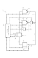
- FIG. 1 is a schematic configuration diagram of a vehicle air conditioner 1 according to an embodiment of the present invention.
- the vehicle air conditioner 1 according to the present embodiment is mounted on a plug-in hybrid vehicle (hereinafter referred to as a vehicle).
- a vehicle-mounted battery (driving battery) for supplying electric power to the traveling motor is mounted on the vehicle.
- the in-vehicle battery is likely to become high temperature because it outputs high-voltage electric power, and is provided with a cooling device in order to prevent an excessive increase in temperature in summer or when the vehicle is stopped when traveling wind cannot be obtained.
- the on-vehicle battery cooling device uses an air conditioner that adjusts the room temperature of the vehicle.
- the vehicle air conditioner (refrigerant circulation device) 1 includes an indoor air conditioner evaporator unit.
- an in-vehicle battery cooling evaporator unit (in-vehicle battery cooling device) 3 is provided in addition to the (vehicle interior air conditioning device) 2.
- an electric compressor 5, a condenser 6, and an indoor air conditioning evaporator unit 2 are interposed in the order of the refrigerant circulation direction.
- the circulation path 4 is branched between the condenser 6 and the indoor air conditioning evaporator unit 2, and a branch flow path 7 is provided to join between the indoor air conditioning evaporator unit 2 and the electric compressor 5.
- An in-vehicle battery cooling evaporator unit 3 is interposed in the branch channel 7.
- an electromagnetic on-off valve 8 for opening and closing the circulation path 4 between the branch position of the branch path 7 and the indoor air conditioning evaporator unit 2 is provided.
- the electric compressor 5 has a function of compressing the refrigerant by operating the compressor with a built-in electric motor.
- the electric compressor 5 is equipped with a control unit 20 (control electronic device) for controlling the operation of the electric motor.
- the control unit 20 is configured by an electronic device such as an inverter for supplying electric power to the electric motor.
- the condenser 6 has a function of exchanging heat between the high-temperature and high-pressure refrigerant compressed by the electric compressor 5 and the outside air and cooling the refrigerant.
- the condenser 6 is provided with a condenser fan 21 for introducing outside air.
- the indoor air conditioning evaporator unit 2 includes an expansion valve 22, an evaporator (vehicle compartment air conditioning evaporator 23), and a blower fan 24.
- the expansion valve 22 has a function of expanding the high-pressure and low-temperature refrigerant discharged from the capacitor 6.
- the blower fan 24 has a function of supplying outdoor or indoor air (air conditioned air) to the vehicle interior air conditioning evaporator 23.
- the vehicle interior air conditioning evaporator 23 has a function of exchanging heat between the refrigerant that has been expanded by the expansion valve 22 to a low temperature and normal pressure and the conditioned air supplied by the blower fan 24.
- the conditioned air cooled by exchanging heat in the vehicle interior air conditioning evaporator 23 is supplied to the vehicle interior to enable temperature adjustment in the vehicle interior.
- the indoor air conditioning evaporator unit 2 is provided in an indoor air conditioning unit 25 (HVAC unit) provided in front of the passenger compartment.
- HVAC unit indoor air conditioning unit
- the inside / outside air switching damper 26 inside / outside air switching means
- the in-vehicle battery cooling evaporator unit 3 includes an expansion valve 31, an evaporator (an in-vehicle battery cooling evaporator 32), and a blower fan 33, and heat exchange is performed in the in-vehicle battery cooling evaporator 32.
- the conditioned air cooled in this way is used for cooling the vehicle-mounted battery.
- the solenoid on-off valve 8 When the solenoid on-off valve 8 is opened, the refrigerant discharged from the condenser 6 can be supplied to the indoor air conditioning evaporator unit 2. When the solenoid on-off valve 8 is closed, all of the refrigerant discharged from the condenser 6 is supplied to the in-vehicle battery cooling evaporator unit 3. It has the function to supply to.
- the electric compressor 5, the condenser fan 21, the blower fan 24 of the evaporator unit 2 for indoor air conditioning, the inside / outside air switching damper 26, the blower fan 33 of the evaporator unit 3 for cooling the on-vehicle battery and the electromagnetic on-off valve 8 include an air conditioner control unit 40 (control means). ).
- the electric compressor 5 is provided with a temperature sensor 41 (temperature detecting means) for detecting the internal temperature Tc of the electric compressor 5, more specifically, the temperature of the control unit 20.
- the refrigerant circulation path 4 is provided with a pressure sensor 42 (pressure detection means) for detecting the refrigerant pressure Pa output from the capacitor 6.
- the air conditioner control unit 40 includes an input / output device, a storage device (ROM, RAM, nonvolatile RAM, etc.), a central processing unit (CPU), and the like.
- the air conditioner control unit 40 controls various vehicle air conditioners such as the electric compressor 5 based on the set temperature, the vehicle interior temperature, etc., and controls various vehicle air conditioners in the normal vehicle air conditioner 1 that controls the temperature in the vehicle interior.
- the on-off battery 8 is closed when the temperature of the in-vehicle battery rises excessively, and only the in-vehicle battery is cooled.
- the internal temperature Tc of the electric compressor 5 is input from the temperature sensor 41 and the refrigerant pressure Pa is input from the pressure sensor 42, so that the inside / outside air switching damper 26, the in-vehicle battery cooling evaporator unit 3 It has a temperature control function that performs control to forcibly change the operating conditions of various vehicle air conditioners such as the blower fan 33, the condenser fan 21, and the electric compressor 5, and suppresses the temperature rise of the control unit 20 of the electric compressor 5. .
- step S10 the pressure Pa is input from the pressure sensor 42, and the internal temperature Tc is input from the temperature sensor 41. Whether the pressure Pa is equal to or higher than the threshold value Pa4 and whether the internal temperature Tc is equal to or higher than the threshold value Tc4. Is determined. When the pressure Pa is not less than the threshold value Pa4 and the internal temperature Tc is not less than the threshold value Tc4, the process proceeds to step S20. If the pressure Pa is less than the threshold value Pa4 or the internal temperature Tc is less than the threshold value Tc4, the process returns to step S10.
- step S20 battery cooling is turned off. Specifically, the blower fan 33 of the in-vehicle battery cooling evaporator unit 3 is stopped. Then, the process proceeds to step S30.
- step S30 the pressure Tc is input from the pressure sensor 42, and the internal temperature Tc is input from the temperature sensor 41 to determine whether the pressure Pa is less than the threshold value Pa4d and the internal temperature Tc is less than the threshold value Tc4d. Determine.
- the threshold value Pa4d is a value slightly lower than the aforementioned threshold value Pa4, and the threshold value Tc4d is a value slightly lower than the threshold value Tc4.
- step S40 When the pressure Pa is less than the threshold value Pa4d and the internal temperature Tc is less than the threshold value Tc4d, the process proceeds to step S40.
- the pressure Pa is equal to or higher than the threshold value Pa4d, or when the internal temperature Tc is equal to or higher than the threshold value Tc4d, the process proceeds to step S50.
- step S40 battery cooling is turned on. Specifically, the blower fan 33 of the on-vehicle battery cooling evaporator unit 3 is operated. Then, the process returns to step S10.
- step S50 the pressure Pa is input from the pressure sensor 42 and the internal temperature Tc is input from the temperature sensor 41, and it is determined whether or not the pressure Pa is equal to or higher than the threshold value Pa1 and the internal temperature Tc is equal to or higher than the threshold value Tc1. Determine.
- the process proceeds to step S60. If the pressure Pa is less than the threshold value Pa1, or if the internal temperature Tc is less than the threshold value Tc1, the process returns to step S30.
- step S60 the forced inside air mode is set. Specifically, the inside / outside air switching damper 26 is operated so that the conditioned air supplied to the vehicle interior air conditioning evaporator 23 is forced into the inside air. Then, the process proceeds to step S70.
- step S70 the pressure Tc is input from the pressure sensor 42 and the internal temperature Tc is input from the temperature sensor 41, and it is determined whether or not the pressure Pa is less than the threshold value Pa1d and the internal temperature Tc is less than the threshold value Tc1d. Determine.
- the threshold value Pa1d is a value slightly lower than the aforementioned threshold value Pa1
- the threshold value Tc1d is a value slightly lower than the threshold value Tc1.
- step S80 If the pressure Pa is equal to or higher than the threshold value Pa1d or the internal temperature Tc is equal to or higher than the threshold value Tc1d, the process proceeds to step S90.
- step S80 the forced inside air mode is canceled. Then, the process returns to step S50.
- step S90 the pressure Pa is input from the pressure sensor 42 and the internal temperature Tc is input from the temperature sensor 41, and it is determined whether or not the pressure Pa is equal to or higher than the threshold value Pa2 and the internal temperature Tc is equal to or higher than the threshold value Tc2. Determine. When the pressure Pa is not less than the threshold value Pa2 and the internal temperature Tc is not less than the threshold value Tc2, the process proceeds to step S100. If the pressure Pa is less than the threshold value Pa2 or the internal temperature Tc is less than the threshold value Tc2, the process returns to step S70.
- step S100 the voltage of the blower fan 33 of the in-vehicle battery cooling evaporator unit 3 is reduced, that is, the rotational speed of the blower fan 33 is reduced. Then, the process proceeds to step S110.
- step S110 the pressure Tc is input from the pressure sensor 42, and the internal temperature Tc is input from the temperature sensor 41. Whether the pressure Pa is less than the threshold value Pa2d and whether the internal temperature Tc is less than the threshold value Tc2d is determined. Determine.
- the threshold value Pa2d is a value slightly lower than the aforementioned threshold value Pa2, and the threshold value Tc2d is a value slightly lower than the threshold value Tc2.
- step S120 If the pressure Pa is equal to or higher than the threshold value Pa2d, or the internal temperature Tc is equal to or higher than the threshold value Tc2d, the process proceeds to step S130.
- step S120 the voltage drop of the blower fan 33 of the in-vehicle battery cooling evaporator unit 3 is released. Then, the process returns to step S90.
- step S130 the pressure Pa is input from the pressure sensor 42 and the internal temperature Tc is input from the temperature sensor 41, and it is determined whether the pressure Pa is equal to or higher than the threshold value Pa3 and whether the internal temperature Tc is equal to or higher than the threshold value Tc3. Determine. When the pressure Pa is not less than the threshold value Pa3 and the internal temperature Tc is not less than the threshold value Tc3, the process proceeds to step S140. If the pressure Pa is less than the threshold value Pa3 or the internal temperature Tc is less than the threshold value Tc3, the process returns to step S110.
- step S140 the rotational speed of the condenser fan 21 is forcibly set to the highest set value Hi. Then, the process proceeds to step S150.
- step S150 the pressure Tc is input from the pressure sensor 42, and the internal temperature Tc is input from the temperature sensor 41. Whether the pressure Pa is less than the threshold value Pa3d and whether the internal temperature Tc is less than the threshold value Tc3d is determined. Determine.
- the threshold value Pa3d is a value slightly lower than the aforementioned threshold value Pa3, and the threshold value Tc3d is a value slightly lower than the threshold value Tc3.
- the process proceeds to step S160.
- the pressure Pa is equal to or higher than the threshold value Pa3d, or when the internal temperature Tc is equal to or higher than the threshold value Tc3d, the process proceeds to step S170.
- step S160 the forced setting of the capacitor fan 21 to the high setting value Hi is canceled. Then, the process returns to step S130.
- step S170 the pressure Pa is input from the pressure sensor 42 and the internal temperature Tc is input from the temperature sensor 41, and it is determined whether or not the pressure Pa is equal to or higher than the threshold value Pa5 and the internal temperature Tc is equal to or higher than the threshold value Tc5. Determine.
- the process proceeds to step S180.
- the pressure Pa is less than the threshold value Pa5, or when the internal temperature Tc is less than the threshold value Tc5, the process returns to step S150.
- step S180 the rotational speed of the electric compressor 5 is changed. Specifically, the rotational speed of the electric compressor 5 is reduced. Then, this routine ends.
- the threshold values Tc1 to Tc5 and Pa1 to Pa5 may be set as appropriate according to the ability of various vehicle air conditioners and the influence on the load.
- the internal temperature threshold values (Tc1 to Tc5) and the pressure threshold values (Pa1 to Pa5) do not necessarily have to be set to different values.
- various vehicle air conditioners provided in the vehicle air conditioner 1 are changed to reduce the load on the electric compressor 5.
- the cooling of the in-vehicle battery can be stopped and the load on the electric compressor 5 can be reduced.
- the heat in the vehicle interior air conditioning evaporator 23 is maintained while maintaining the vehicle interior temperature by exchanging heat between the indoor air and the refrigerant, that is, by switching the internal / external air switching damper 26 to the internal air mode. The exchange amount can be suppressed, and the load on the electric compressor 5 can be reduced.
- the amount of heat exchange in the in-vehicle battery cooling evaporator 32 can be reduced, and the load on the electric compressor 5 can be reduced.
- the condenser fan 21 to the high set value Hi, the refrigerant temperature after passing through the condenser 6 can be lowered, and the cooling capacity can be increased. Thereby, compression in the electric compressor 5 can be suppressed and a load can be reduced.
- any control for reducing the load of the electric compressor 5 described above since the amount of refrigerant supplied to the indoor air conditioning evaporator unit 2 is ensured, the air conditioning capability of the vehicle interior can be maintained.
- the load on the electric compressor 5 can be reduced, of course, by reducing the rotational speed of the electric compressor 5.
- the rotation speed of the electric compressor 5 is reduced when the load of the electric compressor 5 increases, but also various other types such as the blower fan 33, the inside / outside air switching damper 26, and the condenser fan 21 of the in-vehicle battery cooling evaporator unit 3.
- the load of the electric compressor 5 can be finely reduced, and the temperature rise of the control unit 20 can be effectively suppressed.
- by changing the operating conditions of various vehicle air conditioners as described above it is possible to suppress a decrease in the air conditioning capability in the vehicle interior, and the comfort of passengers in the vehicle interior can be improved.
- the control unit 20 since the operating conditions of various vehicle air conditioners are changed based on both the internal temperature Tc of the electric compressor 5 and the refrigerant pressure Pa, the control unit 20 operates based on the refrigerant pressure Pa.
- the load can be reduced before the temperature rises, and the temperature rise of the control unit 20 can be reliably suppressed based on the internal temperature Tc of the electric compressor 5.
- the cooling of the in-vehicle battery is stopped, the mode is changed to the inside air mode, the rotational speed of the blower fan 33 of the evaporator unit 3 for cooling the on-vehicle battery is increased, the rotational speed of the condenser fan 21 is increased, and the rotational speed of the electric compressor 5 is decreased.
- the load of the electric compressor 5 is reduced by these five controls.
- the cooling of the vehicle battery is stopped, the change to the inside air mode, and the rotation speed of the blower fan 33 of the evaporator unit 3 for cooling the vehicle battery is reduced.
- the present invention can be widely applied to vehicles provided with both the indoor air conditioning evaporator unit 2 and the on-vehicle battery cooling evaporator unit 3, and can be applied to, for example, a hybrid vehicle and an electric vehicle.
- Vehicle air conditioner refrigerant circulation device
- Evaporator unit for cabin air conditioning equipment for cabin air conditioning
- In-vehicle battery cooling evaporator unit in-vehicle battery cooling device
- Electric Compressor 23
- Evaporator for Car Air Conditioning 26 Inside / Outside Air Switching Damper (Inside / Outside Air Switching Means)
- In-vehicle battery cooling evaporator 33
- Blower fan 40
- Air conditioner control unit (control means) 41
- Temperature sensor temperature detection means
- Pressure sensor pressure detection means
Landscapes
- Engineering & Computer Science (AREA)
- Power Engineering (AREA)
- Mechanical Engineering (AREA)
- Transportation (AREA)
- Physics & Mathematics (AREA)
- Thermal Sciences (AREA)
- Life Sciences & Earth Sciences (AREA)
- Sustainable Development (AREA)
- Sustainable Energy (AREA)
- Air-Conditioning For Vehicles (AREA)
- Electric Propulsion And Braking For Vehicles (AREA)
Abstract
車両の室内を冷房する室内空調用エバポレータユニット2と、車両に搭載された車載電池を冷却する車載電池冷却用エバポレータ32を含む車載電池冷却用エバポレータユニット3と、室内空調用エバポレータユニット2及び車載電池冷却用エバポレータユニット3に冷媒を圧縮して供給する電動コンプレッサ5と、電動コンプレッサ5の内部温度を検出する温度センサ41と、電動コンプレッサ5により圧縮された冷媒の圧力を検出する圧力センサ42と、電動コンプレッサ5の内部温度及び冷媒の圧力に基づいて、電動コンプレッサ5の負荷を低減させるべく車載電池冷却用エバポレータ32の作動を規制するエアコンコントロールユニット40を備える。
Description
本発明は、車両に搭載される冷媒循環装置における、電動コンプレッサの熱保護技術に関する。
近年開発されている電気自動車やハイブリッド車のように、エンジンを搭載していない、あるいは走行時にエンジンを作動していない場合のある車両では、車両の空調装置における冷媒圧縮用に、電動コンプレッサが用いられている。
また、電気自動車やハイブリッド車は、走行駆動用のために高電圧の電池を搭載しており、当該車載電池の温度を適温に保持するために、車両の空調装置を利用して、車載電池の温度を調節する構成の車両も提案されている。
また、電気自動車やハイブリッド車は、走行駆動用のために高電圧の電池を搭載しており、当該車載電池の温度を適温に保持するために、車両の空調装置を利用して、車載電池の温度を調節する構成の車両も提案されている。
このような車両では、例えば冷媒の循環路に、車室内用のエバポレータの他に、車載電池冷却用のエバポレータを備え、同一のコンプレッサにより、車室内用のエバポレータ及び車載電池冷却用のエバポレータの両方に圧縮した冷媒を供給するような構成となっている。
このように、車室内用の空調装置に用いられる熱媒体の一部を用いて、車両に搭載される機器の温度調整を行う技術は、従来より公知となっている。例えば特許文献1では、エンジンの冷却水を車内暖房装置に用いており、この冷却水の一部を用いてギヤボックスと熱交換し、ギヤボックスの温度調整が可能になっている。
このように、車室内用の空調装置に用いられる熱媒体の一部を用いて、車両に搭載される機器の温度調整を行う技術は、従来より公知となっている。例えば特許文献1では、エンジンの冷却水を車内暖房装置に用いており、この冷却水の一部を用いてギヤボックスと熱交換し、ギヤボックスの温度調整が可能になっている。
ところで、上記のような電動コンプレッサには、その作動を制御するために電子機器が備えられている。この電動コンプレッサに設けられた制御用電子機器は、電動コンプレッサを通過する冷媒によって若干の温度上昇は抑えられるものの、電動コンプレッサの負荷が高くなると駆動電流の上昇に伴い高く温度上昇する虞がある。
特に、上記のように同一のコンプレッサで車室内と車載電池の両方の温度調整が可能な車両においては、電動コンプレッサの負荷が更に高くなり、電動コンプレッサの制御用電子機器の温度が許容を超えて上昇してしまうといった虞がある。
特に、上記のように同一のコンプレッサで車室内と車載電池の両方の温度調整が可能な車両においては、電動コンプレッサの負荷が更に高くなり、電動コンプレッサの制御用電子機器の温度が許容を超えて上昇してしまうといった虞がある。
本発明は、上述した課題を解決すべくなされたものであり、その目的とするところは、電動コンプレッサを用いて車室内と車載電池の両方の温度調整が可能な車両の空調装置において、電動コンプレッサの温度上昇を抑制して、電動コンプレッサの保護を図ることが可能な車両空調装置を提供することにある。
上記の目的を達成するべく、請求項1の冷媒循環装置は、車両の室内を冷房する車室内空調用装置と、車両に搭載された車載電池を冷却する車載電池冷却用エバポレータを含む車載電池冷却用装置と、車室内空調用装置、および、車載電池冷却用装置の一方又は両方に、冷媒を圧縮して供給する電動コンプレッサと、電動コンプレッサの温度を検出する温度検出手段と、電動コンプレッサにより圧縮された冷媒の圧力を検出する圧力検出手段と、電動コンプレッサの温度及び冷媒の圧力に基づいて、電動コンプレッサの負荷を低減させるべく、車載電池冷却用エバポレータの作動を規制する制御手段と、を備えることとした。
また、請求項2の冷媒循環装置は、請求項1において、車室内空調用装置は、車室内空調用エバポレータと、該車室内空調用エバポレータにおいて冷媒と熱交換して車室内に供給される空調風を室外空気、又は、室内空気に切換可能な内外気切換手段とを有し、制御手段は、電動コンプレッサの負荷を低減させるべく、室内空気を冷媒と熱交換するように内外気切換手段を切換えることとした。
また、請求項3の車両空調装置は、請求項1または2において、車載電池冷却用装置は、車載電池冷却用エバポレータに空調風を供給するブロアファンを有し、制御手段は、電動コンプレッサの負荷を低減させるべく、ブロアファンの回転速度を低下させることとした。
また、請求項4の車両空調装置は、請求項1乃至3のいずれか1項において、電動コンプレッサによって圧縮された冷媒と室外空気とを熱交換して、冷媒を冷却するコンデンサと、コンデンサに室外空気を導入するコンデンサファンと、を有し、制御手段は、電動コンプレッサの負荷を低減させるべく、コンデンサファンの回転速度を高めることとした。
また、請求項5の車両空調装置は、請求項1乃至4のいずれか1項において、電動コンプレッサは、冷媒を圧縮するコンプレッサを作動させる電動モータと、電動モータと隣接して配置され、電動モータの作動を制御する制御用電子機器と、を有し、温度検出手段は、制御用電子機器の温度を検出することとした。
請求項1の発明によれば、電動コンプレッサの温度及び電動コンプレッサにより圧縮された冷媒の圧力に基づいて、電動コンプレッサの負荷を低減させるべく車載電池冷却用エバポレータの作動を規制するので、室内空調用エバポレータによる車室内に対する空調能力を維持した上で、電動コンプレッサの負荷を低減させることができ、車室内の乗員の快適性を損なうことなく、電動コンプレッサの温度上昇、特に電動コンプレッサに備えられる制御用電子機器の温度上昇を抑えることができ、電動コンプレッサの保護を図ることができる。
請求項2の発明によれば、室内空調用エバポレータにおいて室内空気を冷媒と熱交換するように内外気切換手段を切換えることで、室内空調用エバポレータでの熱交換量を抑制して、電動コンプレッサの負荷を低減させることができる。したがって、車室内と車載電池の両方に対する空調能力を維持した上で、電動コンプレッサの負荷を低減させることができ、車室内の乗員の快適性を損なうことなく、電動コンプレッサの温度上昇を抑えて保護を図ることができる。
請求項3の発明によれば、車載電池冷却用エバポレータに空調風を供給するブロアファンの回転速度を低下させることで、車載電池冷却用エバポレータでの熱交換量を抑制して、電動コンプレッサの負荷を低減させることができる。したがって、車室内に対する空調能力を維持した上で、電動コンプレッサの負荷を低減させることができ、車室内の乗員の快適性を損なうことなく、電動コンプレッサの温度上昇を抑えて保護を図ることができる。
請求項4の発明によれば、コンデンサファンの回転速度を高めることで冷媒の冷却効率を向上させ、車載電池冷却用エバポレータでの熱交換量を抑制して、電動コンプレッサの負荷を低減させることができる。
請求項5の発明によれば、温度検出手段により、保護を要する制御用電子機器の温度を直接検出できるので的確に電動コンプレッサの負荷を抑制することができる。
以下、本発明の実施形態について図面を参照しながら説明する。
図1は、本発明の一実施形態に係る車両空調装置1の概略構成図である。
本実施形態に係る車両空調装置1は、プラグインハイブリッド車(以下、車両という)に搭載されている。
車両には、走行モータに電力を供給するための車載電池(駆動用電池)が搭載されている。車載電池は、高電圧の電力を出力するため高温になりやすく、夏期や走行風が得られない車両停止時等において過度な温度上昇を防止するために冷却装置が備えられている。
図1は、本発明の一実施形態に係る車両空調装置1の概略構成図である。
本実施形態に係る車両空調装置1は、プラグインハイブリッド車(以下、車両という)に搭載されている。
車両には、走行モータに電力を供給するための車載電池(駆動用電池)が搭載されている。車載電池は、高電圧の電力を出力するため高温になりやすく、夏期や走行風が得られない車両停止時等において過度な温度上昇を防止するために冷却装置が備えられている。
車載電池の冷却装置は、車両の室内温度を調整する空調装置を利用しており、具体的には、図1に示すように、車両空調装置(冷媒循環装置)1に、室内空調用エバポレータユニット(車室内空調用装置)2の他に、車載電池冷却用エバポレータユニット(車載電池冷却用装置)3を備えている。
車両空調装置1の冷媒の循環路4には、冷媒の循環方向の順番に、電動コンプレッサ5、コンデンサ6、室内空調用エバポレータユニット2が介装されている。更に、本実施形態では、コンデンサ6と室内空調用エバポレータユニット2との間で循環路4が分岐して、室内空調用エバポレータユニット2と電動コンプレッサ5との間で合流する分流路7が設けられている。当該分流路7には、車載電池冷却用エバポレータユニット3が介装されている。また、分流路7の分岐位置と室内空調用エバポレータユニット2との間の循環路4を開閉する電磁開閉弁8が備えられている。
車両空調装置1の冷媒の循環路4には、冷媒の循環方向の順番に、電動コンプレッサ5、コンデンサ6、室内空調用エバポレータユニット2が介装されている。更に、本実施形態では、コンデンサ6と室内空調用エバポレータユニット2との間で循環路4が分岐して、室内空調用エバポレータユニット2と電動コンプレッサ5との間で合流する分流路7が設けられている。当該分流路7には、車載電池冷却用エバポレータユニット3が介装されている。また、分流路7の分岐位置と室内空調用エバポレータユニット2との間の循環路4を開閉する電磁開閉弁8が備えられている。
電動コンプレッサ5は、内蔵する電動モータによってコンプレッサを作動させることで、冷媒を圧縮する機能を有する。電動コンプレッサ5には、電動モータの作動を制御するための制御ユニット20(制御用電子機器)が搭載されている。当該制御ユニット20は、電動モータに電力を供給するためのインバータ等の電子機器によって構成されている。
コンデンサ6は、電動コンプレッサ5によって圧縮された高温高圧の冷媒と外気とを熱交換し、冷媒を冷却する機能を有する。コンデンサ6には、外気を導入するためのコンデンサファン21が備えられている。
コンデンサ6は、電動コンプレッサ5によって圧縮された高温高圧の冷媒と外気とを熱交換し、冷媒を冷却する機能を有する。コンデンサ6には、外気を導入するためのコンデンサファン21が備えられている。
室内空調用エバポレータユニット2は、膨張弁22、エバポレータ(車室内空調用エバポレータ23)及びブロアファン24を備えている。膨張弁22は、コンデンサ6から排出された高圧低温の冷媒を膨張させる機能を有する。ブロアファン24は、車室内空調用エバポレータ23に室外または室内の空気(空調風)を供給する機能を有する。車室内空調用エバポレータ23は、膨張弁22によって膨張され低温常圧となった冷媒と、ブロアファン24によって供給された空調風とを熱交換する機能を有する。車室内空調用エバポレータ23において熱交換して冷却された空調風は、車室内に供給され、車室内の温度調整を可能とする。
また、室内空調用エバポレータユニット2は、車室の前方に備えられる室内空調ユニット25(HVACユニット)に備えられ、室内空調ユニット25には、車室内空調用エバポレータ23に供給される空調風を内気と外気とに切換える内外気切換えダンパ26(内外気切換手段)が備えられている。
車載電池冷却用エバポレータユニット3は、室内空調用エバポレータユニット2と同様に膨張弁31、エバポレータ(車載電池冷却用エバポレータ32)及びブロアファン33を備えており、車載電池冷却用エバポレータ32において熱交換して冷却された空調風は、車載電池の冷却に用いられる。
車載電池冷却用エバポレータユニット3は、室内空調用エバポレータユニット2と同様に膨張弁31、エバポレータ(車載電池冷却用エバポレータ32)及びブロアファン33を備えており、車載電池冷却用エバポレータ32において熱交換して冷却された空調風は、車載電池の冷却に用いられる。
電磁開閉弁8は、開作動時には、コンデンサ6から排出された冷媒を室内空調用エバポレータユニット2に供給可能とし、閉作動時には、コンデンサ6から排出された冷媒の全てを車載電池冷却用エバポレータユニット3に供給させる機能を有する。
電動コンプレッサ5、コンデンサファン21、室内空調用エバポレータユニット2のブロアファン24、内外気切換えダンパ26、車載電池冷却用エバポレータユニット3のブロアファン33及び電磁開閉弁8は、エアコンコントロールユニット40(制御手段)により作動制御される。
電動コンプレッサ5、コンデンサファン21、室内空調用エバポレータユニット2のブロアファン24、内外気切換えダンパ26、車載電池冷却用エバポレータユニット3のブロアファン33及び電磁開閉弁8は、エアコンコントロールユニット40(制御手段)により作動制御される。
更に、電動コンプレッサ5には、電動コンプレッサ5の内部温度Tc、詳しくは制御ユニット20の温度を検出する温度センサ41(温度検出手段)が備えられている。また、冷媒の循環路4には、コンデンサ6から出力された冷媒の圧力Paを検出する圧力センサ42(圧力検出手段)が備えられている。
エアコンコントロールユニット40は、入出力装置、記憶装置(ROM、RAM、不揮発性RAM等)及び中央演算処理装置(CPU)等を含んで構成されている。エアコンコントロールユニット40は、設定温度及び車室内温度等に基づいて、電動コンプレッサ5等の各種車両空調機器を制御して、車室内の温度制御を行う通常の車両空調装置1における各種車両空調機器の作動制御を行うとともに、車載電池の過度な温度上昇時に電磁開閉弁8を閉弁させ、車載電池のみ冷却させる機能を有している。
エアコンコントロールユニット40は、入出力装置、記憶装置(ROM、RAM、不揮発性RAM等)及び中央演算処理装置(CPU)等を含んで構成されている。エアコンコントロールユニット40は、設定温度及び車室内温度等に基づいて、電動コンプレッサ5等の各種車両空調機器を制御して、車室内の温度制御を行う通常の車両空調装置1における各種車両空調機器の作動制御を行うとともに、車載電池の過度な温度上昇時に電磁開閉弁8を閉弁させ、車載電池のみ冷却させる機能を有している。
更に、本実施形態では、温度センサ41から電動コンプレッサ5の内部温度Tcを入力するとともに、圧力センサ42より冷媒の圧力Paを入力して、内外気切換えダンパ26、車載電池冷却用エバポレータユニット3のブロアファン33、コンデンサファン21、電動コンプレッサ5といった各種車両空調機器の作動条件を強制的に変更する制御を行い、電動コンプレッサ5の制御ユニット20の温度上昇を抑制する温度制御機能を有している。
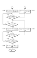
図2、3は、エアコンコントロールユニット40における電動コンプレッサ5の温度制御要領を示すフローチャートである。
本ルーチンは、車両空調装置1の作動時に所定時間毎に繰り返し行なわれる。
始めにステップS10では、圧力センサ42より圧力Paを入力するとともに、温度センサ41から内部温度Tcを入力して、圧力Paが閾値Pa4以上であり、かつ内部温度Tcが閾値Tc4以上であるか否かを判別する。圧力Paが閾値Pa4以上であり、かつ内部温度Tcが閾値Tc4以上である場合には、ステップS20に進む。圧力Paが閾値Pa4未満であるか、または内部温度Tcが閾値Tc4未満である場合には、ステップS10に戻る。
本ルーチンは、車両空調装置1の作動時に所定時間毎に繰り返し行なわれる。
始めにステップS10では、圧力センサ42より圧力Paを入力するとともに、温度センサ41から内部温度Tcを入力して、圧力Paが閾値Pa4以上であり、かつ内部温度Tcが閾値Tc4以上であるか否かを判別する。圧力Paが閾値Pa4以上であり、かつ内部温度Tcが閾値Tc4以上である場合には、ステップS20に進む。圧力Paが閾値Pa4未満であるか、または内部温度Tcが閾値Tc4未満である場合には、ステップS10に戻る。
ステップS20では、電池冷却をオフにする。詳しくは、車載電池冷却用エバポレータユニット3のブロアファン33を停止させる。そして、ステップS30に進む。
ステップS30では、圧力センサ42より圧力Tcを入力するとともに、温度センサ41から内部温度Tcを入力して、圧力Paが閾値Pa4d未満であり、かつ内部温度Tcが閾値Tc4d未満であるか否かを判別する。なお、閾値Pa4dは、前述の閾値Pa4より若干低い値であるとともに、閾値Tc4dは閾値Tc4より若干低い値である。圧力Paが閾値Pa4d未満であり、かつ内部温度Tcが閾値Tc4d未満である場合には、ステップS40に進む。圧力Paが閾値Pa4d以上であるか、または内部温度Tcが閾値Tc4d以上である場合には、ステップS50に進む。
ステップS30では、圧力センサ42より圧力Tcを入力するとともに、温度センサ41から内部温度Tcを入力して、圧力Paが閾値Pa4d未満であり、かつ内部温度Tcが閾値Tc4d未満であるか否かを判別する。なお、閾値Pa4dは、前述の閾値Pa4より若干低い値であるとともに、閾値Tc4dは閾値Tc4より若干低い値である。圧力Paが閾値Pa4d未満であり、かつ内部温度Tcが閾値Tc4d未満である場合には、ステップS40に進む。圧力Paが閾値Pa4d以上であるか、または内部温度Tcが閾値Tc4d以上である場合には、ステップS50に進む。
ステップS40では、電池冷却をONにする。詳しくは、車載電池冷却用エバポレータユニット3のブロアファン33を作動させる。そして、ステップS10に戻る。
ステップS50では、圧力センサ42より圧力Paを入力するとともに、温度センサ41から内部温度Tcを入力して、圧力Paが閾値Pa1以上であり、かつ内部温度Tcが閾値Tc1以上であるか否かを判別する。圧力Paが閾値Pa1以上であり、かつ内部温度Tcが閾値Tc1以上である場合には、ステップS60に進む。圧力Paが閾値Pa1未満であるか、または内部温度Tcが閾値Tc1未満である場合には、ステップS30に戻る。
ステップS50では、圧力センサ42より圧力Paを入力するとともに、温度センサ41から内部温度Tcを入力して、圧力Paが閾値Pa1以上であり、かつ内部温度Tcが閾値Tc1以上であるか否かを判別する。圧力Paが閾値Pa1以上であり、かつ内部温度Tcが閾値Tc1以上である場合には、ステップS60に進む。圧力Paが閾値Pa1未満であるか、または内部温度Tcが閾値Tc1未満である場合には、ステップS30に戻る。
ステップS60では、強制内気モードにする。詳しくは、車室内空調用エバポレータ23に供給される空調風が強制的に内気になるように、内外気切換えダンパ26を作動させる。そして、ステップS70に進む。
ステップS70では、圧力センサ42より圧力Tcを入力するとともに、温度センサ41から内部温度Tcを入力して、圧力Paが閾値Pa1d未満であり、かつ内部温度Tcが閾値Tc1d未満であるか否かを判別する。なお、閾値Pa1dは、前述の閾値Pa1より若干低い値であるとともに、閾値Tc1dは閾値Tc1より若干低い値である。圧力Paが閾値Pa1d未満であり、かつ内部温度Tcが閾値Tc1d未満である場合には、ステップS80に進む。圧力Paが閾値Pa1d以上であるか、または内部温度Tcが閾値Tc1d以上である場合には、ステップS90に進む。
ステップS70では、圧力センサ42より圧力Tcを入力するとともに、温度センサ41から内部温度Tcを入力して、圧力Paが閾値Pa1d未満であり、かつ内部温度Tcが閾値Tc1d未満であるか否かを判別する。なお、閾値Pa1dは、前述の閾値Pa1より若干低い値であるとともに、閾値Tc1dは閾値Tc1より若干低い値である。圧力Paが閾値Pa1d未満であり、かつ内部温度Tcが閾値Tc1d未満である場合には、ステップS80に進む。圧力Paが閾値Pa1d以上であるか、または内部温度Tcが閾値Tc1d以上である場合には、ステップS90に進む。
ステップS80では、強制内気モードを解除する。そして、ステップS50に戻る。
ステップS90では、圧力センサ42より圧力Paを入力するとともに、温度センサ41から内部温度Tcを入力して、圧力Paが閾値Pa2以上であり、かつ内部温度Tcが閾値Tc2以上であるか否かを判別する。圧力Paが閾値Pa2以上であり、かつ内部温度Tcが閾値Tc2以上である場合には、ステップS100に進む。圧力Paが閾値Pa2未満であるか、または内部温度Tcが閾値Tc2未満である場合には、ステップS70に戻る。
ステップS90では、圧力センサ42より圧力Paを入力するとともに、温度センサ41から内部温度Tcを入力して、圧力Paが閾値Pa2以上であり、かつ内部温度Tcが閾値Tc2以上であるか否かを判別する。圧力Paが閾値Pa2以上であり、かつ内部温度Tcが閾値Tc2以上である場合には、ステップS100に進む。圧力Paが閾値Pa2未満であるか、または内部温度Tcが閾値Tc2未満である場合には、ステップS70に戻る。
ステップS100では、車載電池冷却用エバポレータユニット3のブロアファン33の電圧を低下、即ちブロアファン33の回転速度を低下させる。そして、ステップS110に進む。
ステップS110では、圧力センサ42より圧力Tcを入力するとともに、温度センサ41から内部温度Tcを入力して、圧力Paが閾値Pa2d未満であり、かつ内部温度Tcが閾値Tc2d未満であるか否かを判別する。なお、閾値Pa2dは、前述の閾値Pa2より若干低い値であるとともに、閾値Tc2dは閾値Tc2より若干低い値である。圧力Paが閾値Pa2d未満であり、かつ内部温度Tcが閾値Tc2d未満である場合には、ステップS120に進む。圧力Paが閾値Pa2d以上であるか、または内部温度Tcが閾値Tc2d以上である場合には、ステップS130に進む。
ステップS110では、圧力センサ42より圧力Tcを入力するとともに、温度センサ41から内部温度Tcを入力して、圧力Paが閾値Pa2d未満であり、かつ内部温度Tcが閾値Tc2d未満であるか否かを判別する。なお、閾値Pa2dは、前述の閾値Pa2より若干低い値であるとともに、閾値Tc2dは閾値Tc2より若干低い値である。圧力Paが閾値Pa2d未満であり、かつ内部温度Tcが閾値Tc2d未満である場合には、ステップS120に進む。圧力Paが閾値Pa2d以上であるか、または内部温度Tcが閾値Tc2d以上である場合には、ステップS130に進む。
ステップS120では、車載電池冷却用エバポレータユニット3のブロアファン33の電圧低下を解除する。そして、ステップS90に戻る。
ステップS130では、圧力センサ42より圧力Paを入力するとともに、温度センサ41から内部温度Tcを入力して、圧力Paが閾値Pa3以上であり、かつ内部温度Tcが閾値Tc3以上であるか否かを判別する。圧力Paが閾値Pa3以上であり、かつ内部温度Tcが閾値Tc3以上である場合には、ステップS140に進む。圧力Paが閾値Pa3未満であるか、または内部温度Tcが閾値Tc3未満である場合には、ステップS110に戻る。
ステップS130では、圧力センサ42より圧力Paを入力するとともに、温度センサ41から内部温度Tcを入力して、圧力Paが閾値Pa3以上であり、かつ内部温度Tcが閾値Tc3以上であるか否かを判別する。圧力Paが閾値Pa3以上であり、かつ内部温度Tcが閾値Tc3以上である場合には、ステップS140に進む。圧力Paが閾値Pa3未満であるか、または内部温度Tcが閾値Tc3未満である場合には、ステップS110に戻る。
ステップS140では、コンデンサファン21の回転速度を、強制的に最も高い高設定値Hiに設定する。そして、ステップS150に進む。
ステップS150では、圧力センサ42より圧力Tcを入力するとともに、温度センサ41から内部温度Tcを入力して、圧力Paが閾値Pa3d未満であり、かつ内部温度Tcが閾値Tc3d未満であるか否かを判別する。なお、閾値Pa3dは、前述の閾値Pa3より若干低い値であるとともに、閾値Tc3dは閾値Tc3より若干低い値である。圧力Paが閾値Pa3d未満であり、かつ内部温度Tcが閾値Tc3d未満である場合には、ステップS160に進む。圧力Paが閾値Pa3d以上であるか、または内部温度Tcが閾値Tc3d以上である場合には、ステップS170に進む。
ステップS150では、圧力センサ42より圧力Tcを入力するとともに、温度センサ41から内部温度Tcを入力して、圧力Paが閾値Pa3d未満であり、かつ内部温度Tcが閾値Tc3d未満であるか否かを判別する。なお、閾値Pa3dは、前述の閾値Pa3より若干低い値であるとともに、閾値Tc3dは閾値Tc3より若干低い値である。圧力Paが閾値Pa3d未満であり、かつ内部温度Tcが閾値Tc3d未満である場合には、ステップS160に進む。圧力Paが閾値Pa3d以上であるか、または内部温度Tcが閾値Tc3d以上である場合には、ステップS170に進む。
ステップS160では、コンデンサファン21の強制的な高設定値Hiへの設定を解除する。そして、ステップS130に戻る。
ステップS170では、圧力センサ42より圧力Paを入力するとともに、温度センサ41から内部温度Tcを入力して、圧力Paが閾値Pa5以上であり、かつ内部温度Tcが閾値Tc5以上であるか否かを判別する。圧力Paが閾値Pa5以上であり、かつ内部温度Tcが閾値Tc5以上である場合には、ステップS180に進む。圧力Paが閾値Pa5未満であるか、または内部温度Tcが閾値Tc5未満である場合には、ステップS150に戻る。
ステップS170では、圧力センサ42より圧力Paを入力するとともに、温度センサ41から内部温度Tcを入力して、圧力Paが閾値Pa5以上であり、かつ内部温度Tcが閾値Tc5以上であるか否かを判別する。圧力Paが閾値Pa5以上であり、かつ内部温度Tcが閾値Tc5以上である場合には、ステップS180に進む。圧力Paが閾値Pa5未満であるか、または内部温度Tcが閾値Tc5未満である場合には、ステップS150に戻る。
ステップS180では、電動コンプレッサ5の回転速度を変更する。具体的には、電動コンプレッサ5の回転速度を低下させる。そして、本ルーチンを終了する。
なお、上記閾値Tc1~Tc5、Pa1~Pa5は、各種車両空調機器の能力や負荷への影響等に応じて、適宜設定すればよい。また、内部温度の閾値(Tc1~Tc5)、及び圧力の閾値(Pa1~Pa5)については、夫々必ずしも全て異なる値に設定する必要はない。
なお、上記閾値Tc1~Tc5、Pa1~Pa5は、各種車両空調機器の能力や負荷への影響等に応じて、適宜設定すればよい。また、内部温度の閾値(Tc1~Tc5)、及び圧力の閾値(Pa1~Pa5)については、夫々必ずしも全て異なる値に設定する必要はない。
以上のように制御することで、本実施形態の車両空調装置1によれば、温度センサ41によって検出された電動コンプレッサ5の内部温度Tc及び圧力センサ42よって検出された圧縮後の冷媒の圧力Paが各閾値(Tc1~Tc5、Pa1~Pa5)以上となった場合に、車両空調装置1に設けられた各種車両空調機器(車載電池冷却用エバポレータユニット3のブロアファン33、内外気切換えダンパ26、コンデンサファン21、電動コンプレッサ5)の作動条件を変更して、電動コンプレッサ5の負荷を低減させる。
具体的には、車載電池冷却用エバポレータユニット3のブロアファン33を停止させることで、車載電池の冷却を停止させ、電動コンプレッサ5の負荷を低減させことができる。
また、車室内空調用エバポレータ23において室内空気を冷媒と熱交換するように、即ち内気モードに内外気切換えダンパ26を切換えることで、車室内温度を維持しつつ車室内空調用エバポレータ23での熱交換量を抑制することができ、電動コンプレッサ5の負荷を低減させることができる。
また、車室内空調用エバポレータ23において室内空気を冷媒と熱交換するように、即ち内気モードに内外気切換えダンパ26を切換えることで、車室内温度を維持しつつ車室内空調用エバポレータ23での熱交換量を抑制することができ、電動コンプレッサ5の負荷を低減させることができる。
また、車載電池冷却用エバポレータユニット3のブロアファン33の回転速度を低下させることで、車載電池冷却用エバポレータ32での熱交換量を低下させ、電動コンプレッサ5の負荷を低減させることができる。
また、コンデンサファン21を強制的に高設定値Hiにすることで、コンデンサ6通過後の冷媒温度を低下させ、冷房能力を高めることができる。これにより、電動コンプレッサ5における圧縮を抑えて負荷を低減させることができる。
また、コンデンサファン21を強制的に高設定値Hiにすることで、コンデンサ6通過後の冷媒温度を低下させ、冷房能力を高めることができる。これにより、電動コンプレッサ5における圧縮を抑えて負荷を低減させることができる。
更に、上記の電動コンプレッサ5の負荷を低減させる制御については、いずれも室内空調用エバポレータユニット2への冷媒の供給量が確保されるので、車室内に対する空調能力を維持することができる。
また、電動コンプレッサ5の回転速度を低下させることでも、勿論、電動コンプレッサ5の負荷を低減させることができる。
また、電動コンプレッサ5の回転速度を低下させることでも、勿論、電動コンプレッサ5の負荷を低減させることができる。
このように電動コンプレッサ5の内部温度Tc及び冷媒の圧力Paに基づいて車両空調装置1の各種車両空調機器の作動条件を変更することで、電動コンプレッサ5の負荷に見合った方法を選択して電動コンプレッサ5の負荷を低減させることができる。よって、電動コンプレッサ5の温度上昇、特に電動コンプレッサ5に備えられた制御ユニット20の温度上昇を抑制することができ、電動コンプレッサ5の保護を図ることができる。
本実施形態では、電動コンプレッサ5の負荷上昇時に電動コンプレッサ5の回転速度を低下させるだけでなく、車載電池冷却用エバポレータユニット3のブロアファン33、内外気切換えダンパ26、コンデンサファン21といったその他の各種車両空調機器を制御することで、細かに電動コンプレッサ5の負荷を低下させることができ、制御ユニット20の温度上昇を効果的に抑制することができる。更には、上記のように各種車両空調機器の作動条件の変更によって、車室内の空調能力の低下を抑えることも可能となり、車室内の乗員の快適性を向上させることができる。
また、本実施形態では、電動コンプレッサ5の内部温度Tcと冷媒の圧力Paの両方に基づいて、各種車両空調機器の作動条件を変更しているので、冷媒の圧力Paに基づいて制御ユニット20の温度上昇前に負荷を低減させることができるとともに、電動コンプレッサ5の内部温度Tcに基づいて確実に制御ユニット20の温度上昇を抑制することができる。
なお、上記実施形態では、車載電池の冷却停止、内気モードへの変更、車載電池冷却用エバポレータユニット3のブロアファン33の回転速度低下、コンデンサファン21の回転速度増加、電動コンプレッサ5の回転速度低下といった5つの制御で電動コンプレッサ5の負荷を低減させるが、このうち車載電池の冷却停止、内気モードへの変更、及び車載電池冷却用エバポレータユニット3のブロアファン33の回転速度低下のように、車載電池冷却用エバポレータ32の作動を規制するような制御が少なくとも1つあればよく、その上で更に上記5つの制御のいずれかを複数組み合わせてもよい。
また、本願発明は、室内空調用エバポレータユニット2と車載電池冷却用エバポレータユニット3の両方を備えた車両において広く適用することができ、例えばハイブリッド車や電気自動車においても適用可能である。
1 車両空調装置(冷媒循環装置)
2 室内空調用エバポレータユニット(車室内空調用装置)
3 車載電池冷却用エバポレータユニット(車載電池冷却用装置)
5 電動コンプレッサ
23 車室内空調用エバポレータ
26 内外気切換えダンパ(内外気切換手段)
32 車載電池冷却用エバポレータ
33 ブロアファン
40 エアコンコントロールユニット(制御手段)
41 温度センサ(温度検出手段)
42 圧力センサ(圧力検出手段)
2 室内空調用エバポレータユニット(車室内空調用装置)
3 車載電池冷却用エバポレータユニット(車載電池冷却用装置)
5 電動コンプレッサ
23 車室内空調用エバポレータ
26 内外気切換えダンパ(内外気切換手段)
32 車載電池冷却用エバポレータ
33 ブロアファン
40 エアコンコントロールユニット(制御手段)
41 温度センサ(温度検出手段)
42 圧力センサ(圧力検出手段)
Claims (5)
- 車両の室内を冷房する車室内空調用装置と、
前記車両に搭載された車載電池を冷却する車載電池冷却用エバポレータを含む車載電池冷却用装置と、
前記車室内空調用装置、および、前記車載電池冷却用装置の一方又は両方に、冷媒を圧縮して供給する電動コンプレッサと、
前記電動コンプレッサの温度を検出する温度検出手段と、
前記電動コンプレッサにより圧縮された前記冷媒の圧力を検出する圧力検出手段と、
前記電動コンプレッサの温度及び前記冷媒の圧力に基づいて、前記電動コンプレッサの負荷を低減させるべく、前記車載電池冷却用エバポレータの作動を規制する制御手段と、を備えた冷媒循環装置。 - 前記車室内空調用装置は、
前記車室内空調用エバポレータと、
該車室内空調用エバポレータにおいて前記冷媒と熱交換して車室内に供給される空調風を室外空気、又は、室内空気に切換可能な内外気切換手段と、を有し、
前記制御手段は、前記電動コンプレッサの負荷を低減させるべく、前記室内空気を前記冷媒と熱交換するように前記内外気切換手段を切換える、請求項1に記載の冷媒循環装置。 - 前記車載電池冷却用装置は、
前記車載電池冷却用エバポレータに空調風を供給するブロアファンを有し、
前記制御手段は、前記電動コンプレッサの負荷を低減させるべく、前記ブロアファンの回転速度を低下させる、請求項1又は2に記載の冷媒循環装置。 - 前記電動コンプレッサによって圧縮された冷媒と室外空気とを熱交換して、冷媒を冷却するコンデンサと、
前記コンデンサに室外空気を導入するコンデンサファンと、を有し、
前記制御手段は、
前記電動コンプレッサの負荷を低減させるべく、前記コンデンサファンの回転速度を高める、請求項1乃至3のいずれか1項に記載の冷媒循環装置。 - 前記電動コンプレッサは、
冷媒を圧縮するコンプレッサを作動させる電動モータと、
前記電動モータと隣接して配置され、前記電動モータの作動を制御する制御用電子機器と、を有し、
前記温度検出手段は、
前記制御用電子機器の温度を検出する、請求項1乃至4のいずれか1項に記載の冷媒循環装置。
Priority Applications (3)
| Application Number | Priority Date | Filing Date | Title |
|---|---|---|---|
| US14/441,757 US9895959B2 (en) | 2012-12-18 | 2013-11-26 | Refrigerant circulation apparatus with controlled operation of an evporator for on-vehicle battery cooling |
| CN201380066150.6A CN104870225B (zh) | 2012-12-18 | 2013-11-26 | 制冷剂循环设备 |
| EP13863933.1A EP2937236B1 (en) | 2012-12-18 | 2013-11-26 | Refrigerant circulation device |
Applications Claiming Priority (2)
| Application Number | Priority Date | Filing Date | Title |
|---|---|---|---|
| JP2012-276021 | 2012-12-18 | ||
| JP2012276021A JP5743109B2 (ja) | 2012-12-18 | 2012-12-18 | 冷媒循環装置 |
Publications (1)
| Publication Number | Publication Date |
|---|---|
| WO2014097831A1 true WO2014097831A1 (ja) | 2014-06-26 |
Family
ID=50978172
Family Applications (1)
| Application Number | Title | Priority Date | Filing Date |
|---|---|---|---|
| PCT/JP2013/081760 Ceased WO2014097831A1 (ja) | 2012-12-18 | 2013-11-26 | 冷媒循環装置 |
Country Status (5)
| Country | Link |
|---|---|
| US (1) | US9895959B2 (ja) |
| EP (1) | EP2937236B1 (ja) |
| JP (1) | JP5743109B2 (ja) |
| CN (1) | CN104870225B (ja) |
| WO (1) | WO2014097831A1 (ja) |
Cited By (1)
| Publication number | Priority date | Publication date | Assignee | Title |
|---|---|---|---|---|
| CN110536808A (zh) * | 2017-04-26 | 2019-12-03 | 三电汽车空调系统株式会社 | 车用空调装置 |
Families Citing this family (14)
| Publication number | Priority date | Publication date | Assignee | Title |
|---|---|---|---|---|
| GB201520362D0 (en) * | 2015-11-19 | 2016-01-06 | G A H Refrigeration Ltd | Refrigeration system and method |
| CA2913473A1 (en) * | 2015-11-27 | 2017-05-27 | Christer Gotmalm | Method and apparatus for cooling and heating in vehicles |
| CN106196494B (zh) * | 2016-08-01 | 2018-11-09 | 珠海格力电器股份有限公司 | 一种整机过负荷控制方法及装置 |
| KR101875649B1 (ko) * | 2016-10-26 | 2018-07-06 | 현대자동차 주식회사 | 차량용 배터리 냉각 시스템 |
| CN106956567A (zh) * | 2017-05-09 | 2017-07-18 | 合肥天鹅制冷科技有限公司 | 可驻车使用的车载空调制冷系统 |
| FR3067860B1 (fr) * | 2017-06-15 | 2021-04-16 | Airbus Group Sas | Systeme de charge d'au moins une batterie d'accumulateurs d'un vehicule et procede de gestion de recharge de ladite au moins une batterie |
| EP3704427B1 (en) * | 2017-10-31 | 2021-12-01 | Carrier Corporation | Transport refrigeration system and method for controlling the same |
| FR3076606B1 (fr) * | 2018-01-09 | 2020-05-22 | Valeo Systemes Thermiques | Systeme de traitement thermique pour vehicule electrique ou hybride |
| CN111376692B (zh) * | 2018-12-29 | 2022-06-07 | 宇通客车股份有限公司 | 一种车辆、多支路温度调节液冷电源系统及其控制方法 |
| JP7387520B2 (ja) * | 2020-03-31 | 2023-11-28 | サンデン株式会社 | 車両用空気調和装置 |
| CN111829116B (zh) * | 2020-07-27 | 2025-01-14 | 合肥天鹅制冷科技有限公司 | 一用一备空气调节系统 |
| CN112283114A (zh) * | 2020-11-30 | 2021-01-29 | 南京恒天领锐汽车有限公司 | 一种空气压缩机的冷却系统及方法 |
| JP7501410B2 (ja) * | 2021-03-08 | 2024-06-18 | トヨタ自動車株式会社 | 車両用空調制御装置 |
| US12202319B2 (en) * | 2022-06-15 | 2025-01-21 | Ford Global Technologies, Llc | System and method for refrigerant pressure and relief |
Citations (3)
| Publication number | Priority date | Publication date | Assignee | Title |
|---|---|---|---|---|
| JP2003279180A (ja) * | 2002-03-22 | 2003-10-02 | Denso Corp | 車両用冷凍サイクル装置 |
| JP2011105150A (ja) * | 2009-11-18 | 2011-06-02 | Hitachi Ltd | 車両用空調装置 |
| JP2012046163A (ja) | 2010-08-26 | 2012-03-08 | Hyundai Motor Co Ltd | ハイブリッド車両の熱管理システム及び方法 |
Family Cites Families (47)
| Publication number | Priority date | Publication date | Assignee | Title |
|---|---|---|---|---|
| US3984224A (en) * | 1973-12-10 | 1976-10-05 | Dawkins Claude W | Air conditioning system for a motor home vehicle or the like |
| US5605051A (en) * | 1991-04-26 | 1997-02-25 | Nippondenso Co., Ltd. | Automotive air conditioner having condenser and evaporator provided within air duct |
| JP3085335B2 (ja) * | 1991-12-27 | 2000-09-04 | 株式会社デンソー | 空気調和装置 |
| US5507153A (en) * | 1993-03-22 | 1996-04-16 | Seiko Epson Corporation | Electric motor vehicle |
| US5456088A (en) * | 1993-11-12 | 1995-10-10 | Thermo King Corporation | Refrigeration unit and method of operating same |
| JPH07212902A (ja) * | 1993-12-02 | 1995-08-11 | Nippondenso Co Ltd | 電気自動車の空調装置制御システム |
| EP0800940A3 (en) * | 1996-04-10 | 2001-06-06 | Denso Corporation | Vehicular air conditioning system for electric vehicles |
| JP3309742B2 (ja) * | 1996-11-29 | 2002-07-29 | 株式会社デンソー | 車両用空調装置 |
| JP3918319B2 (ja) * | 1998-09-25 | 2007-05-23 | 株式会社デンソー | 電気自動車用空調装置 |
| US6077158A (en) * | 1998-11-12 | 2000-06-20 | Daimlerchrysler Corporation | Air handling controller for HVAC system for electric vehicles |
| US6138466A (en) * | 1998-11-12 | 2000-10-31 | Daimlerchrysler Corporation | System for cooling electric vehicle batteries |
| US6357541B1 (en) * | 1999-06-07 | 2002-03-19 | Mitsubishi Heavy Industries, Ltd. | Circulation apparatus for coolant in vehicle |
| JP4067701B2 (ja) * | 1999-06-10 | 2008-03-26 | カルソニックカンセイ株式会社 | 車両用空調装置 |
| JP3910384B2 (ja) * | 2000-10-13 | 2007-04-25 | 本田技研工業株式会社 | 車両用バッテリ冷却装置 |
| JP2002240547A (ja) * | 2001-02-16 | 2002-08-28 | Toyota Industries Corp | 車両用空調装置及びその運転方法 |
| JP5029980B2 (ja) * | 2001-04-17 | 2012-09-19 | 株式会社ヴァレオジャパン | バッテリー冷却装置 |
| JP2003025832A (ja) * | 2001-07-12 | 2003-01-29 | Denso Corp | 車両用空調装置 |
| US6834511B2 (en) | 2002-03-15 | 2004-12-28 | Calsonic Kansei Corporation | Vehicle air conditioning apparatus |
| US7096925B2 (en) * | 2003-06-19 | 2006-08-29 | General Motors Corporation | Modular electric HVAC systems for vehicles |
| US7259469B2 (en) * | 2003-07-31 | 2007-08-21 | Scs Frigette Inc. | Vehicle auxiliary power unit, assembly, and related methods |
| JP4385678B2 (ja) * | 2003-08-05 | 2009-12-16 | 株式会社デンソー | 車両用バッテリ冷却システム |
| JP4804839B2 (ja) * | 2005-09-05 | 2011-11-02 | カルソニックカンセイ株式会社 | 車両用空調装置の制御システム |
| FR2897016A1 (fr) * | 2006-02-09 | 2007-08-10 | Vehicules Electr Societe Par A | Vehicule automobile electrique ou hybride a systeme de conditionnement thermique valorisant les sources de bas niveau |
| JP4466595B2 (ja) * | 2006-03-28 | 2010-05-26 | トヨタ自動車株式会社 | 冷却システムおよびこれを搭載する自動車並びに冷却システムの制御方法 |
| US20100155018A1 (en) * | 2008-12-19 | 2010-06-24 | Lakhi Nandlal Goenka | Hvac system for a hybrid vehicle |
| US7789176B2 (en) * | 2007-04-11 | 2010-09-07 | Tesla Motors, Inc. | Electric vehicle thermal management system |
| US8049460B2 (en) * | 2007-07-18 | 2011-11-01 | Tesla Motors, Inc. | Voltage dividing vehicle heater system and method |
| US20090249802A1 (en) * | 2008-04-04 | 2009-10-08 | Gm Global Technology Operations, Inc. | Vehicle HVAC and Battery Thermal Management |
| US8215432B2 (en) * | 2008-05-09 | 2012-07-10 | GM Global Technology Operations LLC | Battery thermal system for vehicle |
| US7975757B2 (en) * | 2008-07-21 | 2011-07-12 | GM Global Technology Operations LLC | Vehicle HVAC and RESS thermal management |
| FR2942080B1 (fr) * | 2009-02-09 | 2011-04-01 | Vehicules Electr Soc D | Procede de gestion thermique d'une batterie electrique |
| CN101875290A (zh) * | 2009-04-30 | 2010-11-03 | 比亚迪股份有限公司 | 一种空调系统及控制方法 |
| US9440514B2 (en) * | 2009-08-07 | 2016-09-13 | Mitsubishi Heavy Industries, Ltd. | Vehicle air-conditioning system |
| EP2524829B1 (en) * | 2010-01-15 | 2017-09-13 | Mitsubishi Heavy Industries, Ltd. | Vehicle air-conditioning system and driving control method therefor |
| JP5375764B2 (ja) * | 2010-07-29 | 2013-12-25 | 三菱自動車工業株式会社 | 車両用エアコンシステムの制御装置 |
| US8932743B2 (en) * | 2010-09-30 | 2015-01-13 | GM Global Technology Operations LLC | Thermal management controls for a vehicle having a rechargeable energy storage system |
| DE102010042195A1 (de) * | 2010-10-08 | 2012-04-12 | Robert Bosch Gmbh | Klimatisierungsvorrichtung und Verfahren zum Klimatisieren eines Innenraums und/oder mindestens eines Bauteils eines Elektrofahrzeuges |
| DE102010062869A1 (de) * | 2010-12-10 | 2012-06-14 | Robert Bosch Gmbh | Klimaanlagenvorrichtung, Klimaanlageneinheit, Verfahren zum Klimatisieren eines Innenraumes und Verfahren zum Betreiben einer Klimaanlageneinheit |
| JP5561206B2 (ja) * | 2011-02-25 | 2014-07-30 | 株式会社デンソー | バッテリの充電制御装置 |
| US10522845B2 (en) * | 2011-09-28 | 2019-12-31 | Tesla, Inc. | Battery centric thermal management system utilizing a heat exchanger blending valve |
| WO2013090232A2 (en) * | 2011-12-14 | 2013-06-20 | Magna E-Car Systems Of America, Inc. | Vehicle with traction motor with preemptive cooling of motor fluid circuit prior to cooling of battery fluid circuit |
| WO2013101519A1 (en) * | 2011-12-29 | 2013-07-04 | Magna E-Car Systems Of America, Inc. | Thermal management system for vehicle having traction motor |
| JP6060797B2 (ja) * | 2012-05-24 | 2017-01-18 | 株式会社デンソー | 車両用熱管理システム |
| JP5799924B2 (ja) * | 2012-09-25 | 2015-10-28 | 株式会社デンソー | 冷凍サイクル装置 |
| EP2903854B1 (en) * | 2012-10-04 | 2018-07-04 | Magna E-car Systems Of America, Inc. | Control of compressor outlet pressure based on temperature of thermal load cooled by coolant in electric vehicle |
| US9452659B2 (en) * | 2012-12-31 | 2016-09-27 | GM Global Technology Operations LLC | Method and apparatus for controlling a combined heating and cooling vapor compression system |
| US10293658B2 (en) * | 2016-04-29 | 2019-05-21 | Ford Global Technologies, Llc | Traction battery cooling system for an electrified vehicle |
-
2012
- 2012-12-18 JP JP2012276021A patent/JP5743109B2/ja active Active
-
2013
- 2013-11-26 WO PCT/JP2013/081760 patent/WO2014097831A1/ja not_active Ceased
- 2013-11-26 EP EP13863933.1A patent/EP2937236B1/en active Active
- 2013-11-26 CN CN201380066150.6A patent/CN104870225B/zh active Active
- 2013-11-26 US US14/441,757 patent/US9895959B2/en active Active
Patent Citations (3)
| Publication number | Priority date | Publication date | Assignee | Title |
|---|---|---|---|---|
| JP2003279180A (ja) * | 2002-03-22 | 2003-10-02 | Denso Corp | 車両用冷凍サイクル装置 |
| JP2011105150A (ja) * | 2009-11-18 | 2011-06-02 | Hitachi Ltd | 車両用空調装置 |
| JP2012046163A (ja) | 2010-08-26 | 2012-03-08 | Hyundai Motor Co Ltd | ハイブリッド車両の熱管理システム及び方法 |
Cited By (3)
| Publication number | Priority date | Publication date | Assignee | Title |
|---|---|---|---|---|
| CN110536808A (zh) * | 2017-04-26 | 2019-12-03 | 三电汽车空调系统株式会社 | 车用空调装置 |
| CN110536808B (zh) * | 2017-04-26 | 2023-02-28 | 三电株式会社 | 车用空调装置 |
| US11613165B2 (en) | 2017-04-26 | 2023-03-28 | Sanden Corporation | Air conditioner for vehicle |
Also Published As
| Publication number | Publication date |
|---|---|
| EP2937236A4 (en) | 2017-05-03 |
| CN104870225B (zh) | 2017-03-01 |
| JP5743109B2 (ja) | 2015-07-01 |
| CN104870225A (zh) | 2015-08-26 |
| EP2937236A1 (en) | 2015-10-28 |
| US20150291008A1 (en) | 2015-10-15 |
| US9895959B2 (en) | 2018-02-20 |
| JP2014121212A (ja) | 2014-06-30 |
| EP2937236B1 (en) | 2021-10-20 |
Similar Documents
| Publication | Publication Date | Title |
|---|---|---|
| JP5743109B2 (ja) | 冷媒循環装置 | |
| JP5860360B2 (ja) | 電動車両用熱管理システム | |
| JP7092429B2 (ja) | 車両用空気調和装置 | |
| JP6125330B2 (ja) | 車両用空気調和装置 | |
| US9212838B2 (en) | Cooling device for vehicles and method for controlling and/or regulating a cooling device | |
| US9517678B2 (en) | High-voltage equipment cooling system for electric vehicle and high-voltage equipment cooling method for electric vehicle | |
| WO2019039153A1 (ja) | 車両用空気調和装置 | |
| US20210094443A1 (en) | Cooling system | |
| JP2014037181A (ja) | 電動車両用熱管理システム | |
| JP2013049309A (ja) | 車両用空調装置 | |
| CN105246719A (zh) | 车用空调装置 | |
| US20230130590A1 (en) | Vehicle and method for controlling vehicle | |
| WO2019235412A1 (ja) | 空調装置 | |
| JPWO2012120603A1 (ja) | 車両の空調装置 | |
| US20240059125A1 (en) | Air conditioner for vehicle | |
| JP2012081870A (ja) | 車両用空調装置 | |
| WO2020121737A1 (ja) | 車両用空気調和装置 | |
| JP2014159204A (ja) | 車両用空調装置 | |
| JP2017149324A (ja) | 車両用空調装置 | |
| JP2021035104A (ja) | 車両用冷却装置 | |
| JP5505236B2 (ja) | 車両用空調装置 | |
| WO2018123636A1 (ja) | 車両用空気調和装置 | |
| KR101661345B1 (ko) | 자동차용 공조시스템의 제어 방법 | |
| CN110740889B (zh) | 车用空调装置 | |
| JP2020131846A (ja) | 車両用空気調和装置 |
Legal Events
| Date | Code | Title | Description |
|---|---|---|---|
| 121 | Ep: the epo has been informed by wipo that ep was designated in this application |
Ref document number: 13863933 Country of ref document: EP Kind code of ref document: A1 |
|
| WWE | Wipo information: entry into national phase |
Ref document number: 14441757 Country of ref document: US |
|
| WWE | Wipo information: entry into national phase |
Ref document number: 2013863933 Country of ref document: EP |
|
| NENP | Non-entry into the national phase |
Ref country code: DE |