WO2014098018A1 - インクジェット印刷装置及び液体供給装置 - Google Patents
インクジェット印刷装置及び液体供給装置 Download PDFInfo
- Publication number
- WO2014098018A1 WO2014098018A1 PCT/JP2013/083589 JP2013083589W WO2014098018A1 WO 2014098018 A1 WO2014098018 A1 WO 2014098018A1 JP 2013083589 W JP2013083589 W JP 2013083589W WO 2014098018 A1 WO2014098018 A1 WO 2014098018A1
- Authority
- WO
- WIPO (PCT)
- Prior art keywords
- liquid
- pressure chamber
- pressure
- ink
- supply path
- Prior art date
- Legal status (The legal status is an assumption and is not a legal conclusion. Google has not performed a legal analysis and makes no representation as to the accuracy of the status listed.)
- Ceased
Links
Images





Classifications
-
- B—PERFORMING OPERATIONS; TRANSPORTING
- B41—PRINTING; LINING MACHINES; TYPEWRITERS; STAMPS
- B41J—TYPEWRITERS; SELECTIVE PRINTING MECHANISMS, i.e. MECHANISMS PRINTING OTHERWISE THAN FROM A FORME; CORRECTION OF TYPOGRAPHICAL ERRORS
- B41J2/00—Typewriters or selective printing mechanisms characterised by the printing or marking process for which they are designed
- B41J2/005—Typewriters or selective printing mechanisms characterised by the printing or marking process for which they are designed characterised by bringing liquid or particles selectively into contact with a printing material
- B41J2/01—Ink jet
- B41J2/17—Ink jet characterised by ink handling
- B41J2/175—Ink supply systems ; Circuit parts therefor
- B41J2/17566—Ink level or ink residue control
-
- B—PERFORMING OPERATIONS; TRANSPORTING
- B41—PRINTING; LINING MACHINES; TYPEWRITERS; STAMPS
- B41J—TYPEWRITERS; SELECTIVE PRINTING MECHANISMS, i.e. MECHANISMS PRINTING OTHERWISE THAN FROM A FORME; CORRECTION OF TYPOGRAPHICAL ERRORS
- B41J2/00—Typewriters or selective printing mechanisms characterised by the printing or marking process for which they are designed
- B41J2/005—Typewriters or selective printing mechanisms characterised by the printing or marking process for which they are designed characterised by bringing liquid or particles selectively into contact with a printing material
- B41J2/01—Ink jet
- B41J2/17—Ink jet characterised by ink handling
- B41J2/175—Ink supply systems ; Circuit parts therefor
- B41J2/17503—Ink cartridges
- B41J2/17513—Inner structure
-
- B—PERFORMING OPERATIONS; TRANSPORTING
- B41—PRINTING; LINING MACHINES; TYPEWRITERS; STAMPS
- B41J—TYPEWRITERS; SELECTIVE PRINTING MECHANISMS, i.e. MECHANISMS PRINTING OTHERWISE THAN FROM A FORME; CORRECTION OF TYPOGRAPHICAL ERRORS
- B41J2/00—Typewriters or selective printing mechanisms characterised by the printing or marking process for which they are designed
- B41J2/005—Typewriters or selective printing mechanisms characterised by the printing or marking process for which they are designed characterised by bringing liquid or particles selectively into contact with a printing material
- B41J2/01—Ink jet
- B41J2/17—Ink jet characterised by ink handling
- B41J2/175—Ink supply systems ; Circuit parts therefor
- B41J2/17503—Ink cartridges
- B41J2/17556—Means for regulating the pressure in the cartridge
-
- B—PERFORMING OPERATIONS; TRANSPORTING
- B41—PRINTING; LINING MACHINES; TYPEWRITERS; STAMPS
- B41J—TYPEWRITERS; SELECTIVE PRINTING MECHANISMS, i.e. MECHANISMS PRINTING OTHERWISE THAN FROM A FORME; CORRECTION OF TYPOGRAPHICAL ERRORS
- B41J2/00—Typewriters or selective printing mechanisms characterised by the printing or marking process for which they are designed
- B41J2/005—Typewriters or selective printing mechanisms characterised by the printing or marking process for which they are designed characterised by bringing liquid or particles selectively into contact with a printing material
- B41J2/01—Ink jet
- B41J2/17—Ink jet characterised by ink handling
- B41J2/175—Ink supply systems ; Circuit parts therefor
- B41J2/17596—Ink pumps, ink valves
-
- B—PERFORMING OPERATIONS; TRANSPORTING
- B41—PRINTING; LINING MACHINES; TYPEWRITERS; STAMPS
- B41J—TYPEWRITERS; SELECTIVE PRINTING MECHANISMS, i.e. MECHANISMS PRINTING OTHERWISE THAN FROM A FORME; CORRECTION OF TYPOGRAPHICAL ERRORS
- B41J2/00—Typewriters or selective printing mechanisms characterised by the printing or marking process for which they are designed
- B41J2/005—Typewriters or selective printing mechanisms characterised by the printing or marking process for which they are designed characterised by bringing liquid or particles selectively into contact with a printing material
- B41J2/01—Ink jet
- B41J2/17—Ink jet characterised by ink handling
- B41J2/175—Ink supply systems ; Circuit parts therefor
- B41J2/17503—Ink cartridges
- B41J2/17513—Inner structure
- B41J2002/17516—Inner structure comprising a collapsible ink holder, e.g. a flexible bag
-
- B—PERFORMING OPERATIONS; TRANSPORTING
- B41—PRINTING; LINING MACHINES; TYPEWRITERS; STAMPS
- B41J—TYPEWRITERS; SELECTIVE PRINTING MECHANISMS, i.e. MECHANISMS PRINTING OTHERWISE THAN FROM A FORME; CORRECTION OF TYPOGRAPHICAL ERRORS
- B41J2/00—Typewriters or selective printing mechanisms characterised by the printing or marking process for which they are designed
- B41J2/005—Typewriters or selective printing mechanisms characterised by the printing or marking process for which they are designed characterised by bringing liquid or particles selectively into contact with a printing material
- B41J2/01—Ink jet
- B41J2/17—Ink jet characterised by ink handling
- B41J2/175—Ink supply systems ; Circuit parts therefor
- B41J2/17566—Ink level or ink residue control
- B41J2002/17586—Ink level or ink residue control using ink bag deformation for ink level indication
Definitions
- the present invention relates to an ink jet printing apparatus and a liquid supply apparatus.
- the liquid ejecting apparatus described in Patent Literature 1 includes a bubble unit that uses a flexible film member that is displaced based on a negative pressure generated as the liquid in the pressure chamber decreases. The liquid supply from the liquid container to the pressure chamber is controlled.
- the flexible film member used in the liquid ejecting apparatus described in Patent Document 1 has a low gas barrier property (air tightness), and cavitation (gas dissolved in the ink is bubbled inside the liquid ejecting head to eject the ink). A phenomenon in which ink cannot be ejected, and ink cannot be ejected.
- the present invention has been made in view of the above problems, and an object thereof is to provide an ink jet printing apparatus and a liquid supply apparatus that are excellent in gas barrier properties in an ink supply path of a liquid ejecting head.
- an ink jet printing apparatus includes a liquid supply unit that supplies a liquid to a liquid ejecting head that discharges a liquid onto a medium, and the liquid supply unit stores a liquid container.
- the liquid supply unit Connected to a supply path that connects the liquid jet head, stores a liquid from the liquid container therein, and supplies the liquid jet head to the liquid jet head.
- the liquid container and the pressure chamber And a valve that opens and closes the supply path, and a negative pressure generator that applies a biasing force in a direction that separates the distance between the opposing inner walls of the pressure chamber. It is characterized by being a bag-like body formed of a resin material whose wall surface is displaced with a change in the amount of liquid stored in the container.
- the liquid supply means supplies the liquid in the liquid container to the liquid ejecting head.
- the liquid container and the liquid jet head are connected via a supply path.
- a pressure chamber for storing the liquid is connected inside the supply path, and the liquid in the liquid container is pressurized by opening and closing the supply path by a valve provided between the liquid container and the pressure chamber. It is designed to be supplied to the room.
- the urging force in the direction of separating the distance between the inner walls facing each other is applied to the pressure chamber by the negative pressure generating unit.
- the pressure chamber is a bag-like body formed of a resin material whose wall surface is displaced as the amount of liquid stored inside changes. And a pressure chamber bends so that the distance between inner walls may leave
- the pressure chamber has a negative pressure
- the liquid supply means causes the liquid jet head to eject a liquid by setting a negative pressure in the supply path for supplying the liquid to the liquid jet head.
- the ink jet printing apparatus Since the resin material forming the pressure chamber is excellent in gas barrier properties, the ink jet printing apparatus according to the present invention reduces the occurrence of cavitation in the liquid ejecting head and stabilizes the ejecting characteristics from the liquid ejecting head. be able to. Further, since the resin material forming the pressure chamber is inexpensive, an inexpensive ink jet printing apparatus can be provided.
- the ink jet printing apparatus includes a pressure detection unit that detects a pressure in the supply path, and the liquid when the pressure in the supply path detected by the pressure detection unit falls below a predetermined pressure. It is preferable to further comprise control means for determining that the amount of liquid in the container has fallen below a predetermined amount.
- the pressure in the supply path for supplying the liquid to the liquid ejecting head is detected by the pressure detecting means.
- the control means detects the amount of liquid in the liquid container based on the pressure detected by the pressure detection means. That is, the control means determines that the remaining amount of liquid in the liquid container has fallen below a predetermined amount when the pressure detected by the pressure detection means falls below a predetermined pressure.
- the remaining amount of liquid in the liquid container can be detected by detecting the pressure in the liquid supply path. Therefore, when the control unit determines that the remaining amount of liquid in the liquid container is less than the predetermined amount, the control unit switches to supplying the liquid from the spare liquid container to the liquid ejecting head, or replaces the liquid container to the user. By notifying the printer, it is possible to prevent a printing failure due to running out of ink even during continuous printing for a long time.
- the pressure detection unit includes a capacitance detection unit that detects a displacement of the wall surface of the pressure chamber, and detects a displacement of the wall surface of the pressure chamber detected by the capacitance detection unit. Therefore, it is preferable to detect the pressure in the supply path.
- the pressure detection means detects the pressure in the supply path by detecting the displacement of the wall surface of the pressure chamber by the capacity detection unit.
- the control means detects the remaining amount of liquid in the liquid container based on the pressure in the supply path detected by the pressure detection means, so that the remaining amount of liquid can be grasped in advance. Printing defects can be prevented.
- the pressure detection means is provided in the supply path, and detects an intermediate pack for storing the liquid from the liquid container and a displacement of a wall surface of the intermediate pack.
- the intermediate pack is a bag-like body formed of a resin material whose wall surface is displaced in accordance with a change in the amount of liquid stored therein, and the pressure detection means includes the capacity detection unit.
- the pressure detection means includes the capacity detection unit.
- the pressure detection unit detects the displacement of the wall surface of the intermediate pack by the capacity detection unit, and based on the detected displacement amount of the wall surface, the pressure in the supply path for supplying the liquid to the liquid ejecting head is detected.
- the intermediate pack provided in the supply path is a bag-like body formed of a resin material whose wall surface is displaced in accordance with a change in the amount of liquid stored therein.
- the pressure detection means detects the pressure in the supply path by detecting the displacement of the wall surface of the intermediate pack by the capacity detection unit.
- the control means detects the remaining amount of liquid in the liquid container based on the pressure in the supply path detected by the pressure detection means, so that the remaining amount of liquid can be grasped in advance. Printing defects can be prevented.
- the liquid supply means further includes a case having higher rigidity than the pressure chamber, and a part of the pressure chamber is bonded to the case.
- the pressure chamber which is a bag-like body formed of a flexible resin material, is provided in the apparatus by being bonded in the case having a rigidity higher than that of the pressure chamber. It can be provided in a desired direction at a desired position. Therefore, by providing the pressure chamber accommodated in such a case in the apparatus in a state where the supply direction of the liquid stands up along the side surface of the apparatus, space saving can be realized and the space is narrow. A plurality of liquid supply means can be provided in the space.
- the liquid supply means is mounted in the carriage of the liquid ejecting head, the influence of the inertia force generated by the scanning movement of the carriage on the liquid in the pressure chamber can be reduced. Occurrence of cavitation that occurs and pressure fluctuation in the pressure chamber can be reduced.
- a plate-like body having higher rigidity than the resin material is provided in the pressure chamber.
- the pressure chamber it is possible to prevent the pressure chamber from being deformed in an unexpected direction. For example, when detecting the displacement of the wall surface of the pressure chamber, it is possible to prevent a detection failure. Further, when the liquid supply means is mounted in the carriage of the liquid ejecting head, it is possible to prevent the liquid in the pressure chamber from moving suddenly even if inertia force is generated by the scanning movement of the carriage. Thereby, generation of cavitation caused by scanning movement of the carriage and pressure fluctuation in the pressure chamber can be reduced.
- a liquid supply apparatus is a liquid supply apparatus that supplies liquid to a liquid ejecting head that discharges liquid to a medium, and is connected to a supply path that connects a liquid container that stores the liquid and the liquid ejecting head.
- a pressure chamber for storing the liquid from the liquid container and supplying the liquid jet head to the liquid ejecting head; and a valve provided in the supply path between the liquid container and the pressure chamber for opening and closing the supply path.
- a negative pressure generating section that applies a biasing force in a direction that separates the distance between the opposing inner walls of the pressure chamber, and the wall of the pressure chamber is displaced in accordance with a change in the amount of liquid stored therein. It is characterized by being a bag-like body formed of a resin material.
- the pressure chamber formed of a resin material having an excellent gas barrier property causes the liquid jet head to discharge the liquid by setting a negative pressure in the supply path for supplying the liquid to the liquid jet head.
- the occurrence of cavitation in the head is reduced, and the ejection characteristics of the liquid ejecting head can be stabilized.
- the ink jet printing apparatus 100 includes an ink supply unit (liquid that supplies ink in a liquid container 20 to an ink jet head (liquid ejecting head) 22 that ejects ink (liquid) onto a recording medium (medium).
- Supply means 10
- FIG. 2 is a schematic diagram illustrating an ink supply path in the ink jet printing apparatus according to the embodiment of the present invention.
- the liquid container 20 and the ink supply unit 10, and the ink supply unit 10 and the inkjet head 22 are connected by a supply path 21.
- the ink supply unit 10 may be provided separately from the ink jet head 22, or may be provided in the carriage of the ink jet head 22 to be on-carriage.
- the liquid container 20 is a container that stores ink ejected by the inkjet head 22.
- the ink in the liquid container 20 is supplied to the ink supply unit 10 and the inkjet head 22 via the supply path 21.
- the liquid container 20 has a gas barrier property, and the liquid container 20 and the supply path 21 are preferably connected by a joint member or the like that can prevent gas from entering.
- the liquid container 20 is preferably a container formed of a material having excellent gas barrier properties, and may be, for example, a resin ink pack and an ink tank.
- the liquid container 20 may be a large-capacity container that can be used in an industrial inkjet printing apparatus that is expected to be continuously operated.
- a plurality of liquid containers 20 may be provided as spare liquid containers.
- one liquid container 20 runs out of ink, it is switched to another liquid container 20 to perform ink jetting. Ink may be supplied to the head 22.
- the supply path 21 connects between the liquid container 20 and the inkjet head 22, and configures a path for supplying ink from the liquid container 20 to the inkjet head 22.
- the supply path 21 allows the liquid container 20 and the ink supply unit 10 to communicate with each other, and allows the ink supply unit 10 and the inkjet head 22 to communicate with each other.
- the supply path 21 is a tube having a cavity through which ink passes, and is preferably formed of a material having excellent gas barrier properties.
- the supply path 21 preferably has flexibility from the viewpoint of easy accommodation in the inkjet printing apparatus 100.
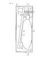
- FIG. 1 is a schematic diagram illustrating an example of an ink supply unit included in an ink jet printing apparatus according to an embodiment of the present invention.
- the pressure chamber 11 may be provided in the case 14.
- the ink supply unit 10 adjusts the pressure in the ink supply path constituted by the liquid container 20, the supply path 21, and the inkjet head 22, thereby preventing the ink jet head 22 from causing problems such as cavitation. It functions as a damper for discharging ink stably. Since the ink supply unit 10 includes a group of members for adjusting the pressure in the ink supply path such as the valve 12, the ink supply unit 10 may be referred to as a bubble unit.
- the pressure chamber 11 is connected to a supply path 21 that connects the liquid container 20 and the inkjet head 22.
- the supply path 21 on the ink jet head 22 side is a supply path 21a
- the supply path 21 on the liquid container 20 side is a supply path 21b.
- the pressure chamber 11 stores the ink supplied from the liquid container 20 to the pressure chamber 11 through the supply path 21b and supplies the ink to the inkjet head 22 through the supply path 21a.
- the pressure chamber 11 is a bag-like body formed of a resin material whose wall surface is displaced in accordance with a change in the amount of liquid stored therein. That is, the pressure chamber 11 is formed of a flexible resin material whose wall surface is displaced as the amount of liquid stored in the pressure chamber 11 changes. This resin material may have flexibility to be bent by the urging force applied from the negative pressure generating unit 13, that is, when the urging force is applied from the negative pressure generating unit, the pressure chamber 11 A resin material that bends and deforms may be used.
- the biasing force applied to the pressure chamber 11 by the negative pressure generating unit 13 is, for example, a force such that the pressure in the pressure chamber 11 is ⁇ 0.5 kPa or more and ⁇ 3.0 kPa or less with respect to the atmospheric pressure. May be.
- Examples of the resin material forming the pressure chamber 11 include polypropylene, polyethylene, polyethylene terephthalate, nylon, and polyamide, and a multilayer in which an aluminum foil or an aluminum vapor deposition layer is provided on these resin materials as necessary. It may be structured.
- the pressure chamber 11 may be an ink pack formed from such a resin material. Since the pressure chamber 11 is formed of such a resin material, it is excellent in gas barrier properties and can be obtained at low cost.
- the pressure chamber 11 When the amount of ink stored in the pressure chamber 11 decreases, the pressure chamber 11 is displaced in a direction in which the distance between the opposing inner walls approaches, and when the amount of ink stored in the interior increases, the pressure chamber 11 is displaced in a direction in which the distance between the opposing inner walls increases. It is formed as follows. That is, in the pressure chamber 11, the ink storage space expands or contracts according to the amount of ink stored inside.
- a stirring member 17 that stirs ink stored inside may be stored.
- the stirring member 17 include a resin or metal spherical body.
- a plurality of stirring members 17 may be stored in the pressure chamber 11.
- the pressure chamber 11 may be provided with a plate-like body having higher rigidity than the resin material forming the pressure chamber 11 therein.
- the size, installation method, and the like of the plate-like body are not limited as long as the flow of ink from the supply path 21b to the supply path 21a is not blocked.
- the plate-like body may be provided so as to partition the pressure chamber 11 into a plurality of liquid chambers. Further, the plate-like body may be provided with holes. Thereby, the rigidity of the pressure chamber 11 can be increased without hindering the flow of ink.
- the ink supply unit 10 is mounted in the carriage of the inkjet head 22, it is possible to prevent the liquid in the pressure chamber 11 from moving suddenly even if an inertial force is generated by the scanning movement of the carriage. Thereby, generation of cavitation caused by scanning movement of the carriage and pressure fluctuation in the pressure chamber 11 can be reduced. Further, by providing a plate member having high rigidity in the pressure chamber 11, it is possible to prevent the pressure chamber 11 from being deformed in an unexpected direction and closing the movement path of the stirring member 17. Can be secured.
- connection port with the supply path 21 a on the ink jet head 22 side is above the liquid level when the liquid of 5% to 50% of the volume of the pressure chamber 11 is accommodated in the pressure chamber 11. It is preferable to be provided. More preferably, the connection port with the supply path 21 a on the ink jet head 22 side is above the liquid level when 15% or more and 40% or less of the volume of the pressure chamber 11 is accommodated in the pressure chamber 11. More preferably, the liquid of 25% or more and 40% or less of the volume of the pressure chamber 11 is provided above the liquid surface when the pressure chamber 11 is accommodated.
- connection port with the supply path 21 a on the inkjet head 22 side is provided on the upper side, so that more ink can be accommodated in the pressure chamber 11.
- the displacement amount can be sufficiently detected, and the detection accuracy is improved.
- the pressure chamber 11 is preferably provided with its longitudinal direction parallel to the direction of gravity. Thus, by providing the pressure chamber 11 vertically, it is possible to reduce the influence of the inertial force due to the carriage operation.
- the connection port with the supply path 21 a on the inkjet head 22 side is preferably provided so as to lead out ink in a direction perpendicular to the scanning movement direction of the carriage. Thereby, the pressure fluctuation of the ink supplied to the inkjet head 22 due to the inertia force generated by the scanning movement of the carriage can be prevented.
- the valve 12 is provided in a supply path 21b between the liquid container 20 and the pressure chamber 11, and adjusts the amount of ink flowing from the liquid container 20 into the pressure chamber 11 by opening and closing the supply path 21b.
- the valve 12 can be configured by a known diaphragm valve.
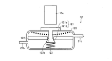
- FIG. 3 is a schematic diagram illustrating an example of a valve included in the ink supply 10 illustrated in FIG. 1.
- the valve body 121 includes an outer part 121 a located outside the liquid chamber 120 and an inner part 121 b located inside the liquid chamber 120.
- the interior of the liquid chamber 120 is divided into a liquid chamber on the liquid container 20 side and a liquid chamber on the pressure chamber 11 side by a partition plate 122 having a liquid chamber flow path 122a.
- the inner part 121b of the valve body 121 is provided so as to penetrate the liquid chamber flow path 122a.
- the inner part 121b of the valve body 121 is connected to a spring 123 connected to the inner wall of the liquid chamber 120 on the pressure chamber 11 side, and is biased by the spring 123 in a direction to close the liquid chamber flow path 122a. .
- the valve 12 is configured such that when the outer portion 121a is pressed by a contact portion 13c of the negative pressure generating portion 13 described later, the liquid chamber flow passage 122a is opened and the liquid is supplied from the supply passage 21b to the pressure chamber 11.
- the abutting portion 13c presses the outer portion 121a the outer portion 121a displaces the side wall of the liquid chamber 120 to the inside (displaced to the position indicated by the broken line in FIG. 3), and the inner portion 121b attaches the spring 123. It moves in the direction to cancel the force, and the liquid chamber flow path 122a opens.
- the ink from the supply path 21b flows from the liquid chamber on the liquid container 20 side into the liquid chamber on the pressure chamber 11 side, and the amount of ink in the pressure chamber 11 increases.
- the contact portion 13c presses the outer portion 121a of the valve 12 when the ink amount in the pressure chamber 11 falls below a predetermined amount, so that the valve 12 causes the ink amount in the pressure chamber 11 to fall below a predetermined amount. Only when the ink volume in the pressure chamber 11 exceeds a predetermined level.
- the predetermined amount of ink in the pressure chamber 11 can be appropriately set according to the size of the pressure chamber, the amount of ink droplets ejected from the inkjet head 22, and the like.
- the negative pressure generation unit 13 applies an urging force in a direction in which the distance between the opposing inner walls of the pressure chamber 11 is increased. Since the pressure chamber 11 is formed so as to be bent by the biasing force applied from the negative pressure generating unit 13, the pressure chamber 11 is bent by the negative pressure generating unit 13 applying the biasing force, and the pressure chamber 11 Can be made negative pressure.
- the negative pressure generating unit 13 is bonded to the pressure chamber 11 at the bonding unit 13a, and is displaced in a direction away from the pressure chamber 11 by its own weight with the fixing unit 13b serving as a fulcrum.
- the wall surface of the pressure chamber 11 on the 13a side is displaced in a direction away from the opposing inner wall.
- the negative pressure generator 13 is provided below the pressure chamber 11 in the gravity direction.
- the negative pressure generating unit 13 generates an urging force in a direction in which the distance between the opposing inner walls in the pressure chamber 11 is separated.
- the wall surface of the pressure chamber 11 on the bonding portion 13a side is bent and displaced by the urging force applied by the negative pressure generating portion 13, and the pressure chamber 11 becomes negative pressure.
- the supply passage 21 connected to the pressure chamber 11 also has a negative pressure. As described above, the negative pressure in the pressure chamber 11 and the supply path 21 is maintained by the negative pressure generation unit 13, so that ink can be stably ejected from the inkjet head 22.
- the fixing part 13b is fixed in the case 14.
- the contact part 13 c is attached to the negative pressure generating part 13.
- the negative pressure generating unit 13 accompanies the displacement of the wall surface of the pressure chamber 11. Is displaced, the distance between the contact portion 13c and the valve 12 approaches, and the contact portion 13c contacts the valve 12.
- the valve 12 is pressed by the contact portion 13 c to open the ink flow path, and the ink flows into the pressure chamber 11.
- the valve 12 is Opened and refilled with ink in the pressure chamber 11.
- the case 14 accommodates the pressure chamber 11.
- the case 14 has a structure having higher rigidity than the pressure chamber 11.
- Examples of the material constituting the case 14 include metals and resins, but it is preferable to use a lightweight and inexpensive resin. Specifically, polypropylene, polyethylene, polyethylene terephthalate, or the like may be used.
- the case 14 is bonded to a position facing the bonding portion 13a of the pressure chamber in the bonding portion 14a. As a result, the position of the pressure chamber 11 itself is not displaced with the displacement of the negative pressure generating unit 13, and the distance between the inner walls of the pressure chamber 11 is displaced.
- the pressure chamber 11 which is a bag-like body formed of a flexible resin material, is bonded to the highly rigid case 14 and provided in the inkjet printing apparatus 100.
- the ink supply unit 10 can be provided in a desired direction at a desired position. Accordingly, space can be saved by providing the pressure chamber 11 accommodated in the case 14 in the ink jet printing apparatus 100 with the ink supply direction standing along the side surface of the apparatus. It is also possible to provide a plurality of ink supply units 10 in a narrow space.
- the inertia force generated by the scanning movement of the carriage causes the liquid in the pressure chamber 11. Can be reduced. Thereby, generation of cavitation caused by scanning movement of the carriage and pressure fluctuation in the pressure chamber 11 can be reduced.
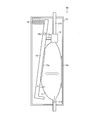
- FIG. 4 is a schematic diagram illustrating another example of the ink supply unit provided in the ink jet printing apparatus according to the embodiment of the present invention.
- the same components as those in FIG. 1 are denoted by the same member numbers. Accordingly, the ink supply unit 40 will be described in detail only with respect to differences from the ink supply unit 10, and details of other points will be omitted.
- a weight 15 is provided on a surface opposite to the surface of the bonding portion 13a on the opposite side of the bonding portion 13a with the fixing portion 13b interposed therebetween. Further, a spring 16 is provided at a position facing the weight 15 with the negative pressure generating unit 13 interposed therebetween.
- the negative pressure generating unit 13 is located above the pressure chamber 11 in the gravity direction.
- the weight 15 side of the fixed unit 13b is displaced in a direction approaching the pressure chamber 11 due to the weight of the weight 15. Then, the force in the direction approaching the pressure chamber 11 due to the weight of the weight 15 is transmitted as a force in the direction away from the pressure chamber 11 to the bonding portion 13a via the fixing portion 13b, and the distance between the inner walls of the pressure chamber 11 is determined. It becomes the urging force in the direction of separating.
- the spring 16 applies a force in a direction away from the pressure chamber 11 to the negative pressure generating unit 13 on the side of the weight 15 relative to the fixed portion 13b in order to adjust the force in the direction approaching the pressure chamber 11 by the weight 15. .
- the negative pressure generating unit 13 may have an end opposite to the side where the weight 15 is provided protruding toward the pressure chamber 11. Thereby, if the displacement amount of the wall surface of the pressure chamber 11 is detected, the displacement amount can be sufficiently detected even if the displacement amount of the wall surface of the pressure chamber 11 is small.
- the negative pressure generation unit 13 can be provided above the pressure chamber 11 in the gravity direction by providing the negative pressure generation unit 13 with the weight 15 and the spring 16.
- FIG. 5 is a schematic diagram illustrating another example of the ink supply unit provided in the ink jet printing apparatus according to the embodiment of the present invention.
- the same components as those in FIG. 1 are denoted by the same member numbers. Accordingly, the ink supply unit 50 will be described in detail only with respect to differences from the ink supply unit 10, and details of other points will be omitted.
- the negative pressure generating unit 13 is provided below the pressure chamber 11 in the gravity direction.
- the weight 15 is provided on a surface opposite to the fixed portion 13b across the adhesive portion 13a and facing away from the surface on the adhesive portion 13a side.
- the weight 15 side of the fixed unit 13 b is displaced in a direction away from the pressure chamber 11 due to the weight of the weight 15.
- the force in the direction away from the pressure chamber 11 due to the weight of the weight 15 is transmitted to the bonding portion 13a as the force in the direction away from the pressure chamber 11, and becomes the biasing force in the direction of separating the distance between the inner walls of the pressure chamber 11.
- connection port between the supply path 21 a on the ink jet head 22 side and the pressure chamber 11 may be provided on the same side as the connection port between the supply path 21 b on the liquid container 20 side and the pressure chamber 11. . That is, the supply path 21a and the supply path 21b may not be provided with the pressure chamber 11 interposed therebetween as shown in FIG. If the connection port to the supply channel 21a and the connection port to the supply channel 21b are provided on the same side of the pressure chamber 11, the supply channel 21a is bent in the direction of the inkjet head 22, and the supply channel 21b is bent in the direction of the liquid container 20. Good.
- the weight 15 is provided in the negative pressure generation unit 13 provided below the pressure chamber 11 in the gravity direction, and the supply path 21 b on the liquid container 20 side and the pressure chamber 11 are connected. It can also be provided on the same side as the connection port.
- FIG. 6 is a schematic diagram illustrating another example of the ink supply unit provided in the ink jet printing apparatus according to the embodiment of the present invention.
- the same components as those in FIG. 1 are denoted by the same member numbers. Accordingly, the ink supply unit 60 will be described in detail only with respect to differences from the ink supply unit 10, and details of other points will be omitted.
- the extending direction of the supply path 21 is provided in parallel to the gravity direction. That is, the longitudinal direction of the pressure chamber 11 is provided in parallel to the gravity direction.
- a spring 16 is attached to the negative pressure generating unit 13 at a position opposite to the bonding portion 13a across the fixed portion 13b and facing away from the surface on the bonding portion 13a side. The spring 16 displaces the spring 16 side of the negative pressure generating unit 13 to the pressure chamber 11 side. Then, the force in the direction approaching the pressure chamber 11 by the spring 16 is transmitted as a force in the direction away from the pressure chamber 11 to the bonding portion 13a via the fixing portion 13b, and the distance between the inner walls of the pressure chamber 11 is separated. It becomes an energizing force.
- the ink supply unit 60 it is possible to suitably maintain the inside of the pressure chamber 11 at a negative pressure even if the length direction of the pressure chamber 11 is arranged in the vertical direction.
- FIG. 7 is a schematic diagram illustrating another example of the ink supply unit provided in the inkjet printing apparatus according to the embodiment of the present invention.
- the same components as those in FIG. 1 are denoted by the same member numbers. Therefore, the ink supply unit 70 will be described in detail only with respect to differences from the ink supply unit 10, and details of other points will be omitted.
- the ink supply unit 60 is provided with the extending direction of the supply path 21 parallel to the direction of gravity. That is, the longitudinal direction of the pressure chamber 11 is provided in parallel to the gravity direction.
- a connecting portion 72 that connects the weight 71 is attached to the negative pressure generating portion 13 at a position opposite to the bonding portion 13a across the fixing portion 13b and facing away from the surface on the bonding portion 13a side.
- the connecting portion 72 includes a rope and a pulley attached to the weight 71, and the negative pressure generating portion 13 is displaced in a direction away from the pressure chamber 11 by the weight of the weight 71.
- the ink supply unit 70 it is possible to suitably maintain the inside of the pressure chamber 11 at a negative pressure even if the length direction of the pressure chamber 11 is arranged in the vertical direction.
- the inkjet printing apparatus 200 includes an ink supply unit 10 that supplies ink in the liquid container 20 to an inkjet head 22 that ejects ink onto a recording medium, a pressure detection unit (pressure detection unit) 23, and the like. It has.
- FIG. 8 is a schematic diagram illustrating an ink supply path in an ink jet printing apparatus according to another embodiment of the present invention.
- the ink jet printing apparatus 200 includes a control unit (not shown).
- the ink jet printing apparatus 200 is different from the ink jet printing apparatus 100 shown in FIG. 2 in that it includes a pressure detection unit 23 and a control unit. Therefore, the inkjet printing apparatus 200 will be described in detail only with respect to differences from the inkjet printing apparatus 100, and details of other points will be omitted.
- the pressure detector 23 detects the pressure in the supply path 21.
- the pressure detection unit 23 may be provided in the supply path 21 and may be provided between the liquid container 20 and the ink supply unit 10 as illustrated in FIG. It may be provided between the inkjet head 22.
- the pressure detection unit 23 may include an intermediate pack 24 and a capacity detection unit 25, and may detect the pressure in the supply path 21 based on the amount of displacement of the wall surface of the intermediate pack 24 detected by the capacity detection unit 25.
- the intermediate pack 24 is provided in the supply path 21 and stores the liquid from the liquid container 20 therein.
- the intermediate pack 24 is a bag-like body formed of a resin material whose wall surface is displaced in accordance with a change in the amount of liquid stored therein.
- the intermediate pack 24 can be configured similarly to the pressure chamber 11.
- the intermediate pack 24 may be accommodated in a case having higher rigidity than the intermediate pack 24.
- the intermediate pack 24 is maintained at a negative pressure inside, and when the amount of stored ink is reduced, the intermediate pack 24 is displaced in a direction in which the distance between the opposing inner walls approaches, and the amount of ink stored inside increases. Then, it forms so that the distance between the inner walls which oppose may displace.
- the ink supply unit 10 and the pressure detection unit 23 may be integrally formed by substituting the intermediate pack 24 with the pressure chamber 11 and causing the pressure chamber 11 to function as the intermediate pack 24. That is, as shown in FIG. 9, a capacity detection unit 25 described later is provided in the ink supply unit 10, and the capacity detection unit 25 detects the displacement of the wall surface of the pressure chamber 11, thereby reducing the amount of ink in the pressure chamber 11. Detect. And the pressure detection part 23 detects the pressure in the supply path 21 based on the displacement amount of the wall surface of the pressure chamber 11. As shown in FIG. 9, the capacity detection unit 25 is provided on the wall surface of the ink supply unit 10, and when the ink amount in the pressure chamber 11 falls below a predetermined amount, the pressure chamber 11 shrinks and becomes negative. What is necessary is just to provide the pressure production
- the capacity detection unit 25 detects the displacement of the wall surface of the intermediate pack 24.
- the capacity detection unit 25 is provided in a case in which the intermediate pack 24 is accommodated, and detects whether the intermediate pack 24 expands or reduces the ink storage space according to the amount of ink stored therein. . For example, when the amount of ink in the intermediate pack 24 falls below a predetermined amount, the capacity detection unit 25 reduces the intermediate pack 24 so that the negative pressure generation unit of the intermediate pack 24 contacts the capacity detection unit 25. What is necessary is just to provide.
- the capacity detection unit 25 detects the amount of displacement of the wall surface of the intermediate pack. Since there is a correlation between the displacement amount of the wall surface of the intermediate pack 24 and the pressure in the supply path 21, the pressure detection unit 23 supplies based on the displacement amount of the wall surface of the intermediate pack 24 detected by the capacity detection unit 25. The pressure in the passage 21 is detected.
- Control means determines that the amount of liquid in the liquid container 20 has fallen below a predetermined amount when the pressure in the supply path 21 detected by the pressure detector 23 is below a predetermined pressure.
- the control means can be configured by a known arithmetic machine such as a computer.
- the control means can prevent printing failure due to unexpected ink out.
- the control unit determines that the remaining amount of the liquid in the liquid container 20 is lower than the predetermined amount, the control unit switches to supply the liquid from the spare liquid container to the inkjet head 22 or notifies the user of the liquid container 20. By notifying the replacement, it is possible to prevent printing failure due to running out of ink even during continuous printing for a long time.
- a liquid supply apparatus is a liquid supply apparatus that supplies liquid to a liquid ejecting head that discharges liquid to a medium, and is connected to a supply path that connects a liquid container that stores the liquid and the liquid ejecting head.
- a pressure chamber for storing the liquid from the liquid container and supplying the liquid jet head to the liquid ejecting head; and a valve provided in the supply path between the liquid container and the pressure chamber for opening and closing the supply path.
- a negative pressure generating section that applies a biasing force in a direction that separates the distance between the opposing inner walls of the pressure chamber, and the wall of the pressure chamber is displaced in accordance with a change in the amount of liquid stored therein. It is characterized by being a bag-like body formed of a resin material.
- one embodiment of the liquid supply apparatus according to the present invention is the ink supply unit 10 of the above-described ink jet printing apparatus 100. Therefore, one embodiment of the liquid supply apparatus according to the present invention conforms to the above description of the ink jet printing apparatus according to the present invention.
- the ink jet printing apparatus 100 includes an ink supply unit 10 that supplies ink to an ink jet head 22 that discharges ink onto a recording medium.
- the ink supply unit 10 connects a liquid container 20 that stores ink and the ink jet head 22.
- a pressure chamber 11 that is connected to the channel 21, stores the ink from the liquid container 20 and supplies the ink to the inkjet head 22, and is provided between the liquid container 20 and the pressure chamber 11 in the supply channel 21.
- a valve 12 that opens and closes the valve 21 and a negative pressure generator 13 that applies a biasing force in a direction that increases the distance between the opposing inner walls of the pressure chamber 11.
- the pressure chamber 11 has an amount of liquid stored therein. It is a bag-like body formed of a resin material whose wall surface is displaced with changes.
- the ink supply unit 10 supplies the ink in the liquid container 20 to the inkjet head 22.
- the liquid container 20 and the inkjet head 22 are connected via a supply path 21.
- a pressure chamber 11 for storing ink is connected to the inside of the supply path 21, and the inside of the supply path 21 is opened and closed by a valve 12 provided between the liquid container 20 and the pressure chamber.
- the ink in 20 is supplied to the pressure chamber 11.
- the urging force in the direction of separating the distance between the inner walls facing each other is applied to the pressure chamber 11 by the negative pressure generator 13.
- the pressure chamber 11 is a bag-like body formed of a resin material whose wall surface is displaced in accordance with a change in the amount of liquid stored inside. Then, the pressure chamber 11 is bent by the urging force applied by the negative pressure generating unit 13 so that the distance between the inner walls is increased. As a result, the pressure chamber 11 has a negative pressure, and the supply passage 21 connected to the pressure chamber 11 also has a negative pressure. In this manner, the ink supply unit 10 causes the ink to be ejected from the inkjet head 22 by setting a negative pressure in the supply path for supplying the ink to the inkjet head 22.
- the ink jet printing apparatus 100 can reduce the occurrence of cavitation in the ink jet head 22 and stabilize the ejection characteristics from the ink jet head 22. it can.
- the resin material forming the pressure chamber 11 is inexpensive, the inexpensive inkjet printing apparatus 100 can be provided.
- the ink jet printing apparatus 200 includes a pressure detection unit 23 that detects the pressure in the supply path 21 and ink in the liquid container 20 when the pressure in the supply path 21 detected by the pressure detection unit 23 falls below a predetermined pressure. Control means for determining that the amount has fallen below a predetermined amount.
- the pressure in the supply path for supplying ink to the inkjet head 22 is detected by the pressure detector 23.
- the control unit detects the amount of ink in the liquid container 20 based on the pressure detected by the pressure detection unit 23. That is, the control means determines that the remaining amount of ink in the liquid container 20 has fallen below a predetermined amount when the pressure detected by the pressure detector 23 falls below a predetermined pressure.
- the remaining amount of ink in the liquid container 20 can be detected by detecting the pressure in the ink supply path. Accordingly, when the control means determines that the remaining amount of ink in the liquid container 20 has fallen below a predetermined amount, the control means switches to supplying ink from the spare liquid container to the inkjet head 22 or notifies the user of the liquid container 20. By notifying the replacement, it is possible to prevent printing failure due to running out of ink even during continuous printing for a long time.
- the pressure detection unit 23 includes a capacitance detection unit 25 that detects the displacement of the wall surface of the pressure chamber 11, and detects the displacement of the wall surface of the pressure chamber 11 detected by the capacitance detection unit 25. The pressure in the supply path 21 is detected.
- the pressure detection unit 23 detects the pressure in the supply path 21 by detecting the displacement of the wall surface of the pressure chamber 11 by the capacity detection unit 25.
- the control means detects the remaining amount of liquid in the liquid container 20, so that the remaining amount of liquid can be grasped in advance. It is possible to prevent printing defects from occurring due to running out of ink.
- the pressure detection unit 23 is provided in the supply path 21, and has an intermediate pack 24 that stores the ink from the liquid container 20 therein, and a capacity that detects a displacement amount of the wall surface of the intermediate pack 24.
- the intermediate pack 24 is a bag-like body formed of a resin material whose wall surface is displaced in accordance with a change in the amount of ink stored therein, and the pressure detection unit 23 is a capacity detection unit 25.
- the pressure in the supply path 21 is detected by detecting the displacement of the wall surface of the intermediate pack 24.
- the pressure detection unit 23 detects the displacement amount of the wall surface of the intermediate pack 24 by the capacitance detection unit 25, and supplies the ink to the inkjet head 22 based on the detected displacement amount of the wall surface.
- the pressure inside is detected.
- the intermediate pack 24 provided in the supply path 21 is a bag-like body formed of a resin material whose wall surface is displaced in accordance with a change in the amount of ink stored therein.
- the pressure detection unit 23 detects the pressure in the supply path 21 by detecting the displacement of the wall surface of the intermediate pack 24 by the capacity detection unit 25.
- the control means detects the ink remaining amount in the liquid container 20 based on the pressure in the supply path 21 detected by the pressure detection unit 23, so that the ink remaining amount can be grasped in advance. It is possible to prevent printing defects from occurring due to running out of ink.
- the ink supply unit 10 further includes a case 14 having higher rigidity than the pressure chamber 11, and a part of the pressure chamber 11 is bonded to the case 14.
- the part 10 can be provided in a desired direction at a desired position in the apparatus. Therefore, space saving can be realized by providing the pressure chamber 11 accommodated in the case 14 in the apparatus in a state where the ink supply direction stands along the side surface of the apparatus, and It is possible to provide a plurality of ink supply units 10 in a narrow space.
- the pressure chamber 11 is provided with a plate-like body having higher rigidity than the resin material.
- the ink supply unit 10 is mounted in the carriage of the inkjet head 22, it is possible to prevent the ink in the pressure chamber 11 from moving suddenly even if an inertial force is generated by the scanning movement of the carriage. Thereby, generation of cavitation caused by scanning movement of the carriage and pressure fluctuation in the pressure chamber 11 can be reduced.
- the ink supply unit 10 is a liquid supply unit that supplies ink to the inkjet head 22 that ejects ink onto a print medium, and is connected to a supply path 21 that connects the liquid container 20 that stores the ink and the inkjet head 22.
- the pressure chamber 11 that stores ink from the liquid container 20 and supplies the ink to the inkjet head 22 and the supply path 21 are provided between the liquid container 20 and the pressure chamber 11 and open and close the supply path 21.
- 12 and a negative pressure generating unit 13 that applies a biasing force in a direction that separates the distance between the opposing inner walls of the pressure chamber 11, and the pressure chamber 11 has a wall surface according to a change in the amount of liquid stored therein.
- the present invention can be used for a liquid supply device in an ink jet recording apparatus.
- Inkjet printer 10 Ink supply section (liquid supply means) DESCRIPTION OF SYMBOLS 11 Pressure chamber 12 Valve 13 Negative pressure production
Landscapes
- Ink Jet (AREA)
Abstract
インク供給経路内のガスバリア性に優れた印刷装置を提供することを課題とする。 解決手段として、インクジェット印刷装置(100)のインク供給部(10)は、供給路(21)に接続された圧力室(11)を備えている。圧力室(11)はガスバリア性に優れた樹脂材料により形成されており、その対向する内壁間の距離を離す方向の付勢力によって撓むことにより、インク供給経路内を負圧にすることができる。
Description
本発明はインクジェット印刷装置及び液体供給装置に関する。
インクジェット印刷装置において、液体噴射ヘッドから液体を噴出するために、液体噴射ヘッド内のインク経路内の圧力を負圧にすることが知られている。このような、インクジェット印刷装置の例として、特許文献1に記載の液体噴射装置が挙げられる。
特許文献1に記載の液体噴射装置は、圧力室内の液体の減少に伴って発生する負圧に基づいて変位する可撓性のフィルム部材を用いたバブルユニットを備え、フィルム部材の変位により供給路を開閉して、液体収容体から圧力室内への液体の供給を制御する。
しかしながら、特許文献1に記載の液体噴射装置において用いられる可撓性のフィルム部材はガスバリア性(気密性)が低く、液体噴射ヘッド内部にキャビテーション(インク内部に溶存する気体が気泡化し、インクが噴射できなくなる現象)が発生して、インクが噴射できなくなるという問題があった。
本発明は、上記問題点に鑑みてなされたものであり、その目的は、液体噴射ヘッドのインク供給路内のガスバリア性に優れたインクジェット印刷装置及び液体供給装置を提供することにある。
上記の課題を解決するために、本発明に係るインクジェット印刷装置は、媒体に液体を吐出する液体噴射ヘッドに液体を供給する液体供給手段を備え、上記液体供給手段は、液体を収容する液体容器と上記液体噴射ヘッドとを接続する供給路に接続され、上記液体容器からの液体を内部に貯留し、上記液体噴射ヘッドに供給する圧力室と、上記供給路において、上記液体容器と上記圧力室との間に設けられ、上記供給路を開閉するバルブと、上記圧力室の対向する内壁間の距離を離す方向に付勢力を付与する負圧生成部とを備え、上記圧力室は、その内部に貯留する液体の量の変化に伴って壁面が変位する樹脂材料によって形成された袋状体であることを特徴としている。
上記の構成によれば、液体供給手段は、液体容器内の液体を液体噴射ヘッドに供給する。液体容器と液体噴射ヘッドとは、供給路を介して接続されている。供給路内には、内部に液体を貯留する圧力室が接続されており、液体容器と圧力室との間に設けられたバルブにより供給路内を開閉することによって、液体容器内の液体を圧力室に供給するようになっている。
圧力室には、負圧生成部によって、対向する内壁間の距離を離す方向の付勢力が付与される。圧力室は、内部に貯留する液体の量の変化に伴って壁面が変位する樹脂材料によって形成された袋状体である。そして、圧力室は、負圧生成部により付与された付勢力によって、内壁間の距離が離れるように撓む。これにより、圧力室内が負圧となり、圧力室に接続された供給路内も負圧になる。このように、液体供給手段によって、液体噴射ヘッドに液体を供給する供給経路内を負圧にすることによって、液体噴射ヘッドから液体を噴射させる。
圧力室を形成する樹脂材料は、ガスバリア性に優れているので、本発明に係るインクジェット印刷装置によれば、液体噴射ヘッド内のキャビテーションの発生が低減し、液体噴射ヘッドからの噴射特性を安定させることができる。また、圧力室を形成する樹脂材料は安価であるため、安価なインクジェット印刷装置を提供することができる。
また、本発明に係るインクジェット印刷装置は、上記供給路内の圧力を検知する圧力検知手段と、上記圧力検知手段が検知した上記供給路内の圧力が、所定の圧力を下回ったとき、上記液体容器内の液体量が所定の量を下回ったと判断する制御手段とをさらに備えていることが好ましい。
上記の構成によれば、圧力検知手段により液体噴射ヘッドに液体を供給する供給経路内の圧力を検知する。そして、制御手段は、圧力検知手段が検知した圧力に基づいて、液体容器内の液体量を検知する。すなわち、制御手段は、圧力検知手段が検知した圧力が、所定の圧力を下回ったとき、液体容器内の液体の残量が所定の量を下回ったと判断する。
このように、液体の供給経路内の圧力を検知することによって、液体容器内の液体の残量を検知することができる。したがって、制御手段が、液体容器内の液体の残量が所定の量を下回ったと判断したときに、予備の液体容器から液体噴射ヘッドに液体を供給するように切り替えたり、ユーザに液体容器の交換を通知したりすることによって、長時間の連続印刷中であっても、インク切れにより印刷不良が生じるのを防ぐことができる。
また、本発明に係るインクジェット印刷装置において、上記圧力検知手段は、上記圧力室の壁面の変位を検知する容量検知部を備え、当該容量検知部が検知した上記圧力室の壁面の変位を検知することによって、上記供給路内の圧力を検知することが好ましい。
上記の構成によれば、圧力検知手段は、容量検知部により圧力室の壁面の変位を検知することによって、供給路内の圧力を検知する。このように圧力検知手段が検知した供給路内の圧力に基づいて、制御手段が液体容器内の液体残量を検知することによって、予め液体残量を把握することが可能であり、インク切れにより印刷不良が生じるのを防ぐことができる。
さらに、本発明に係るインクジェット印刷装置において、上記圧力検知手段は、上記供給路内に設けられ、上記液体容器からの液体を内部に貯留する中間パックと、上記中間パックの壁面の変位を検知する容量検知部とを備え、上記中間パックは、その内部に貯留する液体量の変化に伴って壁面が変位する樹脂材料によって形成された袋状体であり、上記圧力検知手段は、上記容量検知部により上記中間パックの壁面の変位を検知することによって、上記供給路内の圧力を検知することが好ましい。
上記の構成によれば、圧力検知手段は、容量検知部により中間パックの壁面の変位を検知し、検知した壁面の変位量に基づいて、液体噴射ヘッドに液体を供給する供給経路内の圧力を検知する。供給路内に設けられた中間パックは、その内部に貯留する液体量の変化に伴って壁面が変位する樹脂材料によって形成された袋状体である。
すなわち、圧力検知手段は、容量検知部により中間パックの壁面の変位を検知することによって、供給路内の圧力を検知する。このように圧力検知手段が検知した供給路内の圧力に基づいて、制御手段が液体容器内の液体残量を検知することによって、予め液体残量を把握することが可能であり、インク切れにより印刷不良が生じるのを防ぐことができる。
また、本発明に係るインクジェット印刷装置において、上記液体供給手段は、上記圧力室よりも高い剛性を有するケースをさらに備え、上記圧力室の一部が上記ケース内に接着されていることが好ましい。
上記の構成よれば、可撓性を有する樹脂材料により形成された袋状体である圧力室を、圧力室よりも剛性の高いケース内に接着して装置内に設けるので、液体供給手段を装置内の所望の位置において、所望の方向に設けることができる。したがって、このようなケース内に収容した圧力室を、その液体の供給方向が装置の側面に沿うように起立した状態で装置内に設けることによって、省スペース化が実現可能であり、かつ、狭い空間内に複数の液体供給手段を設けることが可能である。
また、液体供給手段を液体噴射ヘッドのキャリッジ内に搭載した場合であっても、キャリッジの走査移動により生じる慣性力が圧力室内の液体に及ぼす影響を低減することができるので、キャリッジの走査移動により生じるキャビテーションの発生及び圧力室内の圧力変動を低減することができる。
さらに、本発明に係るインクジェット印刷装置において、上記圧力室は、その内部に、上記樹脂材料よりも高い剛性を有する板状体が設けられていることが好ましい。
上記の構成によれば、予期しない方向に圧力室が変形するのを防ぐことができるので、例えば、圧力室の壁面の変位を検出する場合に、検出不良となるのを防ぐことができる。また、液体供給手段を液体噴射ヘッドのキャリッジ内に搭載した場合に、キャリッジの走査移動により慣性力が生じても、圧力室内の液体が急激に移動するのを防ぐことができる。これにより、キャリッジの走査移動により生じるキャビテーションの発生及び圧力室内の圧力変動を低減することができる。
本発明に係る液体供給装置は、媒体に液体を吐出する液体噴射ヘッドに液体を供給する液体供給装置であって、液体を収容する液体容器と液体噴射ヘッドとを接続する供給路内に接続され、上記液体容器からの液体を内部に貯留し、上記液体噴射ヘッドに供給する圧力室と、上記供給路において、上記液体容器と上記圧力室との間に設けられ、上記供給路を開閉するバルブと、上記圧力室の対向する内壁間の距離を離す方向に付勢力を付与する負圧生成部とを備え、上記圧力室は、その内部に貯留する液体の量の変化に伴って壁面が変位する樹脂材料によって形成された袋状体であることを特徴としている。
上記の構成によれば、本発明に係るインクジェット印刷装置と同様の効果を奏する。
本発明は、ガスバリア性に優れた樹脂材料によって形成された圧力室により、液体噴射ヘッドに液体を供給する供給経路内を負圧にすることによって、液体噴射ヘッドから液体を吐出させるので、液体噴射ヘッド内のキャビテーションの発生が低減し、液体噴射ヘッドの吐出特性を安定させることができる。
以下、本発明の実施の形態について、図1~8に基づいて以下に詳細に説明する。
〔インクジェット印刷装置100〕
図2に示すように、インクジェット印刷装置100は、記録媒体(媒体)にインク(液体)を吐出するインクジェットヘッド(液体噴射ヘッド)22に、液体容器20内のインクを供給するインク供給部(液体供給手段)10を備えている。図2は、本発明の一実施形態に係るインクジェット印刷装置におけるインク供給経路を説明する模式図である。液体容器20及びインク供給部10、並びに、インク供給部10及びインクジェットヘッド22は、それぞれ供給路21により接続されている。なお、インク供給部10は、図2に示すように、インクジェットヘッド22とは別に設けられていてもよいし、インクジェットヘッド22のキャリッジ内に設けてオンキャリッジにしてもよい。
図2に示すように、インクジェット印刷装置100は、記録媒体(媒体)にインク(液体)を吐出するインクジェットヘッド(液体噴射ヘッド)22に、液体容器20内のインクを供給するインク供給部(液体供給手段)10を備えている。図2は、本発明の一実施形態に係るインクジェット印刷装置におけるインク供給経路を説明する模式図である。液体容器20及びインク供給部10、並びに、インク供給部10及びインクジェットヘッド22は、それぞれ供給路21により接続されている。なお、インク供給部10は、図2に示すように、インクジェットヘッド22とは別に設けられていてもよいし、インクジェットヘッド22のキャリッジ内に設けてオンキャリッジにしてもよい。
(液体容器20)
液体容器20は、インクジェットヘッド22が吐出するインクを貯留する容器である。液体容器20内のインクは、供給路21を介してインク供給部10及びインクジェットヘッド22に供給される。液体容器20は、ガスバリア性を有しており、液体容器20と供給路21とは、気体の侵入を防止可能なジョイント部材等により接続されていることが好ましい。液体容器20としては、ガスバリア性に優れた材料により形成された容器であることが好ましく、例えば、樹脂製のインクパック及びインクタンク等であってもよい。また、液体容器20は、連続稼働が期待される産業用インクジェット印刷装置に使用可能な大容量の容器であってもよい。さらに、インク切れを防止するために、予備の液体容器として、複数の液体容器20が設けられていてもよく、1つの液体容器20がインク切れしたときに、他の液体容器20に切り換えてインクジェットヘッド22にインクを供給してもよい。
液体容器20は、インクジェットヘッド22が吐出するインクを貯留する容器である。液体容器20内のインクは、供給路21を介してインク供給部10及びインクジェットヘッド22に供給される。液体容器20は、ガスバリア性を有しており、液体容器20と供給路21とは、気体の侵入を防止可能なジョイント部材等により接続されていることが好ましい。液体容器20としては、ガスバリア性に優れた材料により形成された容器であることが好ましく、例えば、樹脂製のインクパック及びインクタンク等であってもよい。また、液体容器20は、連続稼働が期待される産業用インクジェット印刷装置に使用可能な大容量の容器であってもよい。さらに、インク切れを防止するために、予備の液体容器として、複数の液体容器20が設けられていてもよく、1つの液体容器20がインク切れしたときに、他の液体容器20に切り換えてインクジェットヘッド22にインクを供給してもよい。
(供給路21)
供給路21は、インクジェット印刷装置100において、液体容器20からインクジェットヘッド22までの間を繋ぎ、液体容器20からインクジェットヘッド22にインクを供給するための経路を構成する。図2に示すように、インクジェット印刷装置100において、供給路21は、液体容器20とインク供給部10とを連通させ、かつ、インク供給部10とインクジェットヘッド22とを連通させる。供給路21は、その内部にインクを通過させる空洞を有する管であり、ガスバリア性に優れた材料により形成されていることが好ましい。また、供給路21は、インクジェット印刷装置100内への収容の容易性の観点から、可撓性を有することが好ましい。
供給路21は、インクジェット印刷装置100において、液体容器20からインクジェットヘッド22までの間を繋ぎ、液体容器20からインクジェットヘッド22にインクを供給するための経路を構成する。図2に示すように、インクジェット印刷装置100において、供給路21は、液体容器20とインク供給部10とを連通させ、かつ、インク供給部10とインクジェットヘッド22とを連通させる。供給路21は、その内部にインクを通過させる空洞を有する管であり、ガスバリア性に優れた材料により形成されていることが好ましい。また、供給路21は、インクジェット印刷装置100内への収容の容易性の観点から、可撓性を有することが好ましい。
(インク供給部10)
インク供給部10は、図1に示すように、圧力室11、バルブ12、及び、負圧生成部13を備えている。図1は、本発明の一実施形態に係るインクジェット印刷装置が備えるインク供給部の例を示す模式図である。また、インク供給部10において、圧力室11は、ケース14内に設けられていてもよい。インク供給部10は、液体容器20、供給路21、及び、インクジェットヘッド22により構成されるインクの供給経路内の圧力を調整することによって、キャビテーション等の不具合を生じさせることなく、インクジェットヘッド22から安定してインクを吐出させるためのダンパとして機能するものである。インク供給部10は、バルブ12等のインクの供給経路内の圧力を調整するための一群の部材を含むため、バブルユニットと称することもある。
インク供給部10は、図1に示すように、圧力室11、バルブ12、及び、負圧生成部13を備えている。図1は、本発明の一実施形態に係るインクジェット印刷装置が備えるインク供給部の例を示す模式図である。また、インク供給部10において、圧力室11は、ケース14内に設けられていてもよい。インク供給部10は、液体容器20、供給路21、及び、インクジェットヘッド22により構成されるインクの供給経路内の圧力を調整することによって、キャビテーション等の不具合を生じさせることなく、インクジェットヘッド22から安定してインクを吐出させるためのダンパとして機能するものである。インク供給部10は、バルブ12等のインクの供給経路内の圧力を調整するための一群の部材を含むため、バブルユニットと称することもある。
<圧力室11>
圧力室11は、液体容器20とインクジェットヘッド22とを接続する供給路21に接続されている。図1において、インクジェットヘッド22側の供給路21を、供給路21aとし、液体容器20側の供給路21を、供給路21bとしている。圧力室11は、供給路21bを介して液体容器20から圧力室11に供給されるインクを内部に貯留し、供給路21aを介してインクジェットヘッド22に供給する。
圧力室11は、液体容器20とインクジェットヘッド22とを接続する供給路21に接続されている。図1において、インクジェットヘッド22側の供給路21を、供給路21aとし、液体容器20側の供給路21を、供給路21bとしている。圧力室11は、供給路21bを介して液体容器20から圧力室11に供給されるインクを内部に貯留し、供給路21aを介してインクジェットヘッド22に供給する。
圧力室11は、その内部に貯留する液体の量の変化に伴って壁面が変位する樹脂材料によって形成された袋状体である。すなわち、圧力室11は、その内部に貯留する液体の量の変化に伴って壁面が変位する可撓性を有する樹脂材料によって形成されている。この樹脂材料は、負圧生成部13から付与される付勢力により撓む可撓性を有していてもよく、つまり、負圧生成部から付勢力が付与されたときに、圧力室11が撓んで変形するような樹脂材料であってもよい。負圧生成部13が圧力室11に付与する付勢力とは、例えば、圧力室11内の圧力が、大気圧に対して-0.5kPa以上、-3.0kPa以下となるような力であってもよい。
圧力室11を形成する樹脂材料としては、例えば、ポリプロピレン、ポリエチレン、ポリエチレンテレフタレート、ナイロン、及びポリアミド等が挙げられ、必要に応じて、これらの樹脂材料上にアルミ箔又はアルミ蒸着層を設けた多層構造としたものであってもよい。圧力室11は、このような樹脂材料から形成されたインクパックであってもよい。圧力室11は、このような樹脂材料により形成されているので、ガスバリア性に優れている上に、安価に得ることができる。
圧力室11は、内部に貯留するインク量が減少すると、対向する内壁間の距離が近づく方向に変位し、内部に貯留するインク量が増加すると、対向する内壁間の距離が離れる方向に変位するように形成されている。すなわち、圧力室11は、内部に貯留するインクの量に応じて、インクの貯留スペースが膨張又は縮小する。
圧力室11内には、内部に貯留するインクを撹拌する撹拌部材17が格納されていてもよい。撹拌部材17としては、例えば、樹脂又は金属製の球状体が挙げられる。撹拌部材17は、圧力室11内に複数格納されていてもよい。このような撹拌部材17を圧力室内に格納することによって、例えば、圧力室11をキャリッジに搭載して走査させる場合、キャリッジの走査移動に伴って撹拌部材17が圧力室11内を移動し、圧力室11内のインクを撹拌することができる。
圧力室11は、内部に、圧力室11を形成する樹脂材料よりも高い剛性を有する板状体が設けられていてもよい。このような板状体は、供給路21bから供給路21aへのインクの流れを遮断しない限り、その大きさ、設置方法等は限定されない。板状体は、圧力室11内を複数の液室に仕切るように設けられていてもよい。また、板状体には、孔が設けられていてもよい。これにより、インクの流れを妨げることなく、圧力室11の剛性を高めることができる。
このように、圧力室11内に剛性の高い板状体を設けることによって、予期しない方向に圧力室11が変形するのを防ぐことができるので、例えば、圧力室11の壁面の変位を検出する場合に、検出不良となるのを防ぐことができる。インク供給部10をインクジェットヘッド22のキャリッジ内に搭載した場合に、キャリッジの走査移動により慣性力が生じても、圧力室11内の液体が急激に移動するのを防ぐことができる。これにより、キャリッジの走査移動により生じるキャビテーションの発生及び圧力室11内の圧力変動を低減することができる。また、圧力室11内に剛性の高い板状体を設けることによって、圧力室11が予期しない方向に変形し、撹拌部材17の運動経路が閉ざされてしまうのを防ぎ、撹拌部材17の運動経路を確保することができる。
圧力室11における、インクジェットヘッド22側の供給路21aとの接続口は、圧力室11の容積の5%以上、50%以下の液体が圧力室11に収容された時の液面よりも上側に設けられていることが好ましい。また、より好ましくは、インクジェットヘッド22側の供給路21aとの接続口は、圧力室11の容積の15%以上、40%以下の液体が圧力室11に収容された時の液面よりも上側、さらに好ましくは、圧力室11の容積の25%以上、40%以下の液体が圧力室11に収容された時の液面よりも上側に設けられている。これにより、圧力室11において、インクジェットヘッド22側の供給路21aとの接続口は、より上部側に設けられることになるので、圧力室11内により多くのインクを収容することができる。これにより、例えば、圧力室11の壁面の変位量を検知する場合に、変位量を十分に検知することが可能であり、検出精度が向上する。
圧力室11は、その長手方向が重力方向に平行に設けられていることが好ましい。このように、圧力室11を縦に設けることによって、キャリッジ操作による慣性力の影響を低減することができる。また、圧力室11において、インクジェットヘッド22側の供給路21aとの接続口は、キャリッジの走査移動方向に対して垂直な方向にインクを導出するように設けられていることが好ましい。これにより、キャリッジの走査移動により生じる慣性力によるインクジェットヘッド22に供給するインクの圧力変動を防止することができる。
<バルブ12>
バルブ12は、液体容器20と圧力室11との間の供給路21bに設けられており、供給路21bを開閉することによって、液体容器20から圧力室11に流れ込むインクの量を調整する。
バルブ12は、液体容器20と圧力室11との間の供給路21bに設けられており、供給路21bを開閉することによって、液体容器20から圧力室11に流れ込むインクの量を調整する。
バルブ12は、公知のダイヤフラム弁により構成することができる。バルブ12としては、例えば、図3に示すような、液室120内外の圧力差に応じて弁体121が変位することによって、インクの流路が開閉するようなバルブを用いることができる。図3は、図1に示すインク供給10が備えるバルブの例を示す模式図である。
図3に示すように、弁体121は、液室120の外側に位置する外側部121aと、液室120の内側に位置する内側部121bとにより構成されている。液室120の内部は、液室内流路122aを有する仕切板122により、液体容器20側の液室と、圧力室11側の液室とに仕切られている。弁体121の内側部121bは、液室内流路122aを貫通するように設けられている。また、弁体121の内側部121bは、液室120の圧力室11側の内壁に連結されたバネ123に連結されており、バネ123により液室内流路122aを塞ぐ方向に付勢されている。
バルブ12は、後述する負圧生成部13の当接部13cにより外側部121aが押さえられたとき、液室内流路122aが開き、供給路21bから圧力室11に液体が供給されるように構成されている。すなわち、当接部13cが外側部121aを押さえると、外側部121aが液室120の側壁をその内側に変位させ(図3中破線で示す位置に変位し)、内側部121bがバネ123の付勢力を打ち消す方向に移動し、液室内流路122aが開く。これにより、供給路21bからのインクが、液体容器20側の液室から圧力室11側の液室に流れ込み、圧力室11内のインク量が増える。
当接部13cは、圧力室11内のインク量が所定の量を下回ったときに、バルブ12の外側部121aを押さえるため、バルブ12は、圧力室11内のインク量が所定の量を下回ったときにのみ開き、圧力室11内のインク量が所定の量以上のときには閉じる。圧力室11内の所定のインク量は、圧力室の大きさ、インクジェットヘッド22から吐出させるインク滴量等に応じて、適宜設定することができる。
<負圧生成部13>
負圧生成部13は、圧力室11の対向する内壁間の距離を離す方向に付勢力を付与するものである。圧力室11は、負圧生成部13から付与される付勢力により撓むように形成されているので、負圧生成部13がこの付勢力を付与することによって、圧力室11が撓み、圧力室11内を負圧にすることができる。
負圧生成部13は、圧力室11の対向する内壁間の距離を離す方向に付勢力を付与するものである。圧力室11は、負圧生成部13から付与される付勢力により撓むように形成されているので、負圧生成部13がこの付勢力を付与することによって、圧力室11が撓み、圧力室11内を負圧にすることができる。
図1に示すように、負圧生成部13は、接着部13aにおいて圧力室11に接着されており、固定部13bを支点として、自重により圧力室11から離れる方向に変位することによって、接着部13a側の圧力室11の壁面を、その対向する内壁から離れる方向に変位させる。図1において、負圧生成部13は、圧力室11よりも重力方向下側に設けられている。
これにより、負圧生成部13は、圧力室11内の対向する内壁間の距離を離す方向の付勢力を生じさせる。負圧生成部13が付与する付勢力により、接着部13a側の圧力室11の壁面が撓んで変位し、圧力室11内が負圧になる。また、圧力室11内が負圧となることによって、圧力室11に接続された供給路21内も負圧になる。このように、負圧生成部13により圧力室11及び供給路21内の負圧が維持されることによって、インクジェットヘッド22からのインクの吐出を安定して行うことができる。
固定部13bは、ケース14内に固定されている。当接部13cは、負圧生成部13に取り付けられている。圧力室11内のインク量が減少し、圧力室11のインクの貯留スペースが縮小して、対向する内壁間の距離が近づいたとき、圧力室11の壁面の変位に伴って負圧生成部13が変位し、当接部13cとバルブ12との距離が近づいて、当接部13cがバルブ12に当接する。さらに圧力室11内のインク量が減少すると、バルブ12が当接部13cに押さえられてインク流路を開き、圧力室11内にインクが流れ込む。このように、圧力室11内にインクが十分に貯留されているときには、バルブ12が閉じていることによって圧力室11内の圧力が保たれ、圧力室11内のインクが減少すると、バルブ12が開かれ圧力室11内のインクが補充される。
<ケース14>
ケース14は、圧力室11を収容するものである。ケース14は、圧力室11よりも高い剛性を有する構造になっている。ケース14を構成する材料として、金属、樹脂等が挙げられるが、軽量で安価な樹脂を用いるとよい。具体的にはポリプロピレン、ポリエチレン、ポリエチレンテレフタレート等を用いるとよい。
ケース14は、圧力室11を収容するものである。ケース14は、圧力室11よりも高い剛性を有する構造になっている。ケース14を構成する材料として、金属、樹脂等が挙げられるが、軽量で安価な樹脂を用いるとよい。具体的にはポリプロピレン、ポリエチレン、ポリエチレンテレフタレート等を用いるとよい。
ケース14は、接着部14aにおいて、圧力室の接着部13aに対向する位置に接着されている。これにより、負圧生成部13の変位に伴って圧力室11自体の位置は変位せず、圧力室11の内壁間の距離が離れるように変位する。
このように、可撓性を有する樹脂材料により形成された袋状体である圧力室11を、剛性の高いケース14内に接着してインクジェット印刷装置100内に設けるので、インクジェット印刷装置100内の所望の位置において、所望の方向にインク供給部10を設けることができる。したがって、このようなケース14内に収容した圧力室11を、そのインクの供給方向が装置の側面に沿うように起立した状態でインクジェット印刷装置100内に設けることによって、省スペース化が実現可能であり、かつ、狭い空間内に複数のインク供給部10を設けることも可能である。
また、ケース14内に圧力室11を収容することによって、インク供給部10をインクジェットヘッド22のキャリッジ内に搭載した場合であっても、キャリッジの走査移動により生じる慣性力が圧力室11内の液体に及ぼす影響を低減することができる。これにより、キャリッジの走査移動により生じるキャビテーションの発生及び圧力室11内の圧力変動を低減することができる。
(インク供給部40)
インク供給部40は、図4に示すように、主に負圧生成部13に錘15及びバネ16を取り付けた点において、図1に示すインク供給部10と異なっている。図4は、本発明の一実施形態に係るインクジェット印刷装置が備えるインク供給部の他の例を示す模式図である。また、図4において、図1と同様の構成については同一の部材番号を付して示している。したがって、インク供給部40については、インク供給部10と異なる点についてのみ詳細に説明し、他の点についてはその詳細を省略する。
インク供給部40は、図4に示すように、主に負圧生成部13に錘15及びバネ16を取り付けた点において、図1に示すインク供給部10と異なっている。図4は、本発明の一実施形態に係るインクジェット印刷装置が備えるインク供給部の他の例を示す模式図である。また、図4において、図1と同様の構成については同一の部材番号を付して示している。したがって、インク供給部40については、インク供給部10と異なる点についてのみ詳細に説明し、他の点についてはその詳細を省略する。
負圧生成部13において、固定部13bを挟んで接着部13aの反対側の位置であって、接着部13a側の面に背向する面には、錘15が設けられている。また、負圧生成部13を挟んで、錘15に対向する位置には、バネ16が設けられている。図4において、負圧生成部13は、圧力室11よりも重力方向上側に位置している。
負圧生成部13は、固定部13bよりも錘15側が、錘15の重さにより圧力室11に近づく方向に変位する。そして、この錘15の重さによる圧力室11に近づく方向の力が、固定部13bを介して接着部13aに、圧力室11から離れる方向の力として伝わり、圧力室11の内壁間の距離を離す方向の付勢力となる。バネ16は、錘15による圧力室11に近づく方向の力を調節するために、固定部13bよりも錘15側の負圧生成部13に圧力室11から離れる方向の力を付与するものである。
負圧生成部13は、図4に示すように、錘15が設けられた側とは反対側の端部が、圧力室11側に突出していてもよい。これにより、圧力室11の壁面の変位量を検知すれば、圧力室11の壁面の変位量が少ない場合であっても、変位量を十分に検知することができる。
このように、インク供給部40によれば、負圧生成部13に錘15及びバネ16を設けることによって、負圧生成部13を圧力室11よりも重力方向上側に設けることができる。
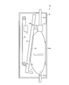
(インク供給部50)
インク供給部50は、図5に示すように、主に負圧生成部13の構成及び供給路21と圧力室11との位置関係において、図1に示すインク供給部10と異なっている。図5は、本発明の一実施形態に係るインクジェット印刷装置が備えるインク供給部の他の例を示す模式図である。また、図5において、図1と同様の構成については同一の部材番号を付して示している。したがって、インク供給部50については、インク供給部10と異なる点についてのみ詳細に説明し、他の点についてはその詳細を省略する。
インク供給部50は、図5に示すように、主に負圧生成部13の構成及び供給路21と圧力室11との位置関係において、図1に示すインク供給部10と異なっている。図5は、本発明の一実施形態に係るインクジェット印刷装置が備えるインク供給部の他の例を示す模式図である。また、図5において、図1と同様の構成については同一の部材番号を付して示している。したがって、インク供給部50については、インク供給部10と異なる点についてのみ詳細に説明し、他の点についてはその詳細を省略する。
図5において、負圧生成部13は、圧力室11よりも重力方向下側に設けられている。そして、錘15は、接着部13aを挟んで固定部13bの反対側の位置であって、接着部13a側の面に背向する面に設けられている。負圧生成部13は、固定部13bよりも錘15側が、錘15の重さにより圧力室11から離れる方向に変位する。この錘15の重さによる圧力室11から離れる方向の力が、接着部13aに、圧力室11から離れる方向の力として伝わり、圧力室11の内壁間の距離を離す方向の付勢力となる。
また、図5において、インクジェットヘッド22側の供給路21aと圧力室11との接続口は、液体容器20側の供給路21bと圧力室11との接続口と同じ側に設けられていてもよい。すなわち、供給路21aと供給路21bとは、図1に示すように、圧力室11を挟んで設けられていなくてもよい。供給路21aとの接続口と供給路21bとの接続口とを、圧力室11の同じ側に設け、供給路21aをインクジェットヘッド22方向に曲げ、供給路21bを液体容器20方向に曲げればよい。
このように、インク供給部50によれば、圧力室11よりも重力方向下側に設けた負圧生成部13に錘15を設けると共に、液体容器20側の供給路21bと圧力室11との接続口と同じ側に設けることもできる。
(インク供給部60)
インク供給部60は、図6に示すように、主に負圧生成部13の構成において、図1に示すインク供給部10と異なっている。図6は、本発明の一実施形態に係るインクジェット印刷装置が備えるインク供給部の他の例を示す模式図である。また、図6において、図1と同様の構成については同一の部材番号を付して示している。したがって、インク供給部60については、インク供給部10と異なる点についてのみ詳細に説明し、他の点についてはその詳細を省略する。
インク供給部60は、図6に示すように、主に負圧生成部13の構成において、図1に示すインク供給部10と異なっている。図6は、本発明の一実施形態に係るインクジェット印刷装置が備えるインク供給部の他の例を示す模式図である。また、図6において、図1と同様の構成については同一の部材番号を付して示している。したがって、インク供給部60については、インク供給部10と異なる点についてのみ詳細に説明し、他の点についてはその詳細を省略する。
図6においては、インク供給部60では、供給路21の延伸方向は重力方向に平行に設けられている。すなわち、圧力室11の長手方向が重力方向に平行に設けられている。負圧生成部13には、固定部13bを挟んで接着部13aの反対側の位置であって、接着部13a側の面に背向する面に、バネ16が取り付けられている。バネ16は、負圧生成部13のバネ16側を圧力室11側に変位させる。そして、このバネ16による圧力室11に近づく方向の力が、固定部13bを介して接着部13aに、圧力室11から離れる方向の力として伝わり、圧力室11の内壁間の距離を離す方向の付勢力となる。
このように、インク供給部60によれば、圧力室11の長さ方向を鉛直方向に配置しても好適に圧力室11内を負圧に維持することが可能である。
(インク供給部70)
インク供給部70は、図7に示すように、主に負圧生成部13の構成において、図1に示すインク供給部10と異なっている。図7は、本発明の一実施形態に係るインクジェット印刷装置が備えるインク供給部の他の例を示す模式図である。また、図7において、図1と同様の構成については同一の部材番号を付して示している。したがって、インク供給部70については、インク供給部10と異なる点についてのみ詳細に説明し、他の点についてはその詳細を省略する。
インク供給部70は、図7に示すように、主に負圧生成部13の構成において、図1に示すインク供給部10と異なっている。図7は、本発明の一実施形態に係るインクジェット印刷装置が備えるインク供給部の他の例を示す模式図である。また、図7において、図1と同様の構成については同一の部材番号を付して示している。したがって、インク供給部70については、インク供給部10と異なる点についてのみ詳細に説明し、他の点についてはその詳細を省略する。
図7においては、インク供給部60は、供給路21の延伸方向は重力方向に平行に設けられている。すなわち、圧力室11の長手方向が重力方向に平行に設けられている。負圧生成部13には、固定部13bを挟んで接着部13aの反対側の位置であって、接着部13a側の面に背向する面に、錘71を連結する連結部72が取り付けられている。連結部72は、例えば、錘71に取り付けられたロープと滑車とにより構成し、錘71の重さにより、負圧生成部13を圧力室11から離れる方向に変位させる。これにより、負圧生成部13において、圧力室11の内壁間の距離を離す方向の付勢力を生じさせる。
このように、インク供給部70によれば、圧力室11の長さ方向を鉛直方向に配置しても好適に圧力室11内を負圧に維持することが可能である。
〔インクジェット印刷装置200〕
図8に示すように、インクジェット印刷装置200は、記録媒体にインクを吐出するインクジェットヘッド22に、液体容器20内のインクを供給するインク供給部10と、圧力検知部(圧力検知手段)23とを備えている。図8は、本発明の他の実施形態に係るインクジェット印刷装置におけるインク供給経路を説明する模式図である。また、インクジェット印刷装置200は、制御手段(図示せず)を備えている。インクジェット印刷装置200は、圧力検知部23及び制御手段を備える点において、図2に示すインクジェット印刷装置100と異なっている。したがって、インクジェット印刷装置200については、インクジェット印刷装置100と異なる点についてのみ詳細に説明し、他の点についてはその詳細を省略する。
図8に示すように、インクジェット印刷装置200は、記録媒体にインクを吐出するインクジェットヘッド22に、液体容器20内のインクを供給するインク供給部10と、圧力検知部(圧力検知手段)23とを備えている。図8は、本発明の他の実施形態に係るインクジェット印刷装置におけるインク供給経路を説明する模式図である。また、インクジェット印刷装置200は、制御手段(図示せず)を備えている。インクジェット印刷装置200は、圧力検知部23及び制御手段を備える点において、図2に示すインクジェット印刷装置100と異なっている。したがって、インクジェット印刷装置200については、インクジェット印刷装置100と異なる点についてのみ詳細に説明し、他の点についてはその詳細を省略する。
(圧力検知部23)
圧力検知部23は、供給路21内の圧力を検知する。圧力検知部23は、供給路21内に設けられていればよく、図8に示すように、液体容器20とインク供給部10との間に設けられていてもよいし、インク供給部10とインクジェットヘッド22との間に設けられていてもよい。圧力検知部23は、中間パック24及び容量検知部25を備え、容量検知部25が検知した中間パック24の壁面の変位量に基づいて、供給路21内の圧力を検知してもよい。
圧力検知部23は、供給路21内の圧力を検知する。圧力検知部23は、供給路21内に設けられていればよく、図8に示すように、液体容器20とインク供給部10との間に設けられていてもよいし、インク供給部10とインクジェットヘッド22との間に設けられていてもよい。圧力検知部23は、中間パック24及び容量検知部25を備え、容量検知部25が検知した中間パック24の壁面の変位量に基づいて、供給路21内の圧力を検知してもよい。
<中間パック24>
中間パック24は、供給路21内に設けられており、液体容器20からの液体を内部に貯留する。中間パック24は、その内部に貯留する液体量の変化に伴って壁面が変位する樹脂材料によって形成された袋状体である。中間パック24は、圧力室11と同様に構成することができる。中間パック24は、中間パック24よりも剛性の高いケース内に収容されていてもよい。
中間パック24は、供給路21内に設けられており、液体容器20からの液体を内部に貯留する。中間パック24は、その内部に貯留する液体量の変化に伴って壁面が変位する樹脂材料によって形成された袋状体である。中間パック24は、圧力室11と同様に構成することができる。中間パック24は、中間パック24よりも剛性の高いケース内に収容されていてもよい。
中間パック24は、圧力室11と同様に、その内部が負圧に維持され、貯留するインク量が減少すると、対向する内壁間の距離が近づく方向に変位し、内部に貯留するインク量が増加すると、対向する内壁間の距離が離れる方向に変位するように形成されている。
したがって、中間パック24を圧力室11で代用し、圧力室11を中間パック24として機能させることで、インク供給部10と圧力検知部23とを一体形成してもよい。すなわち、図9に示すように、後述する容量検知部25をインク供給部10内に設け、容量検知部25が圧力室11の壁面の変位を検知することによって、圧力室11内のインク量を検知する。そして圧力検知部が23は、圧力室11の壁面の変位量に基づいて、供給路21内の圧力を検知する。図9に示すように、容量検知部25は、インク供給部10の壁面に設けられており、圧力室11内のインク量が所定の量を下回ったときに、圧力室11が縮小して負圧生成部13が容量検知部25に当接するように設ければよい。
<容量検知部25>
容量検知部25は、中間パック24の壁面の変位を検知する。容量検知部25は、中間パック24が収容されたケース内に設けられており、中間パック24が、内部に貯留するインクの量に応じて、インクの貯留スペースを膨張又は縮小させるのを検知する。容量検知部25は、例えば、中間パック24内のインク量が所定の量を下回ったときに、中間パック24が縮小して中間パック24の負圧生成部が容量検知部25に当接するように設ければよい。
容量検知部25は、中間パック24の壁面の変位を検知する。容量検知部25は、中間パック24が収容されたケース内に設けられており、中間パック24が、内部に貯留するインクの量に応じて、インクの貯留スペースを膨張又は縮小させるのを検知する。容量検知部25は、例えば、中間パック24内のインク量が所定の量を下回ったときに、中間パック24が縮小して中間パック24の負圧生成部が容量検知部25に当接するように設ければよい。
このように容量検知部25は、中間パックの壁面の変位量を検知する。中間パック24の壁面の変位量と供給路21内の圧力とは、相関関係があるので、圧力検知部23は、容量検知部25が検知した中間パック24の壁面の変位量に基づいて、供給路21内の圧力を検知する。
(制御手段)
制御手段は、圧力検知部23が検知した供給路21内の圧力が、所定の圧力を下回ったとき、液体容器20内の液体量が所定の量を下回ったと判断する。制御手段は、コンピュータ等の公知の演算機により構成することができる。
制御手段は、圧力検知部23が検知した供給路21内の圧力が、所定の圧力を下回ったとき、液体容器20内の液体量が所定の量を下回ったと判断する。制御手段は、コンピュータ等の公知の演算機により構成することができる。
圧力検知部23が検知した供給路21内の圧力が、所定の圧力を下回ると、中間パック24内のインク量が所定のインク量を下回っていることを意味しており、液体容器20から中間パック24に液体が供給されない状態、すなわち、液体容器20がインク切れの状態である。このようなインク切れを制御手段が検知することによって、予期せぬインク切れにより、印刷不良が生じるのを防ぐことができる。
したがって、制御手段が、液体容器20内の液体の残量が所定の量を下回ったと判断したときに、予備の液体容器からインクジェットヘッド22に液体を供給するように切り替えたり、ユーザに液体容器20の交換を通知したりすることによって、長時間の連続印刷中であっても、インク切れにより印刷不良が生じるのを防ぐことができる。
〔液体供給装置〕
本発明に係る液体供給装置は、媒体に液体を吐出する液体噴射ヘッドに液体を供給する液体供給装置であって、液体を収容する液体容器と液体噴射ヘッドとを接続する供給路内に接続され、上記液体容器からの液体を内部に貯留し、上記液体噴射ヘッドに供給する圧力室と、上記供給路において、上記液体容器と上記圧力室との間に設けられ、上記供給路を開閉するバルブと、上記圧力室の対向する内壁間の距離を離す方向に付勢力を付与する負圧生成部とを備え、上記圧力室は、その内部に貯留する液体の量の変化に伴って壁面が変位する樹脂材料によって形成された袋状体であることを特徴としている。
本発明に係る液体供給装置は、媒体に液体を吐出する液体噴射ヘッドに液体を供給する液体供給装置であって、液体を収容する液体容器と液体噴射ヘッドとを接続する供給路内に接続され、上記液体容器からの液体を内部に貯留し、上記液体噴射ヘッドに供給する圧力室と、上記供給路において、上記液体容器と上記圧力室との間に設けられ、上記供給路を開閉するバルブと、上記圧力室の対向する内壁間の距離を離す方向に付勢力を付与する負圧生成部とを備え、上記圧力室は、その内部に貯留する液体の量の変化に伴って壁面が変位する樹脂材料によって形成された袋状体であることを特徴としている。
すなわち、本発明に係る液体供給装置の一実施形態は、上述したインクジェット印刷装置100のインク供給部10である。したがって、本発明に係る液体供給装置の一実施形態は、上述した本発明に係るインクジェット印刷装置の説明に準じる。
〔付記事項〕
インクジェット印刷装置100は、記録媒体にインクを吐出するインクジェットヘッド22にインクを供給するインク供給部10を備え、インク供給部10は、インクを収容する液体容器20とインクジェットヘッド22とを接続する供給路21に接続され、液体容器20からのインクを内部に貯留し、インクジェットヘッド22に供給する圧力室11と、供給路21において、液体容器20と圧力室11との間に設けられ、供給路21を開閉するバルブ12と、圧力室11の対向する内壁間の距離を離す方向に付勢力を付与する負圧生成部13とを備え、圧力室11は、その内部に貯留する液体の量の変化に伴って壁面が変位する樹脂材料によって形成された袋状体である。
インクジェット印刷装置100は、記録媒体にインクを吐出するインクジェットヘッド22にインクを供給するインク供給部10を備え、インク供給部10は、インクを収容する液体容器20とインクジェットヘッド22とを接続する供給路21に接続され、液体容器20からのインクを内部に貯留し、インクジェットヘッド22に供給する圧力室11と、供給路21において、液体容器20と圧力室11との間に設けられ、供給路21を開閉するバルブ12と、圧力室11の対向する内壁間の距離を離す方向に付勢力を付与する負圧生成部13とを備え、圧力室11は、その内部に貯留する液体の量の変化に伴って壁面が変位する樹脂材料によって形成された袋状体である。
上記の構成によれば、インク供給部10は、液体容器20内のインクをインクジェットヘッド22に供給する。液体容器20とインクジェットヘッド22とは、供給路21を介して接続されている。供給路21内には、内部にインクを貯留する圧力室11が接続されており、液体容器20と圧力室との間に設けられたバルブ12により供給路21内を開閉することによって、液体容器20内のインクを圧力室11に供給するようになっている。
圧力室11には、負圧生成部13によって、対向する内壁間の距離を離す方向の付勢力が付与される。圧力室11は、内部に貯留する液体の量の変化に伴って壁面が変位する樹脂材料によって形成された袋状体である。そして、圧力室11は、負圧生成部13により付与された付勢力によって、内壁間の距離が離れるように撓む。これにより、圧力室11内が負圧となり、圧力室11に接続された供給路21内も負圧になる。このように、インク供給部10によって、インクジェットヘッド22にインクを供給する供給経路内を負圧にすることによって、インクジェットヘッド22からインクを噴射させる。
圧力室11を形成する樹脂材料は、ガスバリア性に優れているので、インクジェット印刷装置100によれば、インクジェットヘッド22内のキャビテーションの発生が低減し、インクジェットヘッド22からの噴射特性を安定させることができる。また、圧力室11を形成する樹脂材料は安価であるため、安価なインクジェット印刷装置100を提供することができる。
インクジェット印刷装置200は、供給路21内の圧力を検知する圧力検知部23と、圧力検知部23が検知した供給路21内の圧力が、所定の圧力を下回ったとき、液体容器20内のインク量が所定の量を下回ったと判断する制御手段とをさらに備えている。
上記の構成によれば、圧力検知部23によりインクジェットヘッド22にインクを供給する供給経路内の圧力を検知する。そして、制御手段は、圧力検知部23が検知した圧力に基づいて、液体容器20内のインク量を検知する。すなわち、制御手段は、圧力検知部23が検知した圧力が、所定の圧力を下回ったとき、液体容器20内のインクの残量が所定の量を下回ったと判断する。
このように、インクの供給経路内の圧力を検知することによって、液体容器20内のインクの残量を検知することができる。したがって、制御手段が、液体容器20内のインクの残量が所定の量を下回ったと判断したときに、予備の液体容器からインクジェットヘッド22にインクを供給するように切り替えたり、ユーザに液体容器20の交換を通知したりすることによって、長時間の連続印刷中であっても、インク切れにより印刷不良が生じるのを防ぐことができる。
また、インクジェット印刷装置200において、圧力検知部23は、圧力室11の壁面の変位を検知する容量検知部25を備え、容量検知部25が検知した圧力室11の壁面の変位を検知することによって、供給路21内の圧力を検知する。
上記の構成によれば、圧力検知部23は、容量検知部25により圧力室11の壁面の変位を検知することによって、供給路21内の圧力を検知する。このように圧力検知部23が検知した供給路21内の圧力に基づいて、制御手段が液体容器20内の液体残量を検知することによって、予め液体残量を把握することが可能であり、インク切れにより印刷不良が生じるのを防ぐことができる。
さらに、インクジェット印刷装置200において、圧力検知部23は、供給路21内に設けられ、液体容器20からのインクを内部に貯留する中間パック24と、中間パック24の壁面の変位量を検知する容量検知部25とを備え、中間パック24は、その内部に貯留するインク量の変化に伴って壁面が変位する樹脂材料によって形成された袋状体であり、圧力検知部23は、容量検知部25により中間パック24の壁面の変位を検知することによって、供給路21内の圧力を検知する。
上記の構成によれば、圧力検知部23は、容量検知部25により中間パック24の壁面の変位量を検知し、検知した壁面の変位量に基づいて、インクジェットヘッド22にインクを供給する供給経路内の圧力を検知する。供給路21内に設けられた中間パック24は、その内部に貯留するインク量の変化に伴って壁面が変位する樹脂材料によって形成された袋状体である。
すなわち、圧力検知部23は、容量検知部25により中間パック24の壁面の変位を検知することによって、供給路21内の圧力を検知する。このように圧力検知部23が検知した供給路21内の圧力に基づいて、制御手段が液体容器20内のインク残量を検知することによって、予めインク残量を把握することが可能であり、インク切れにより印刷不良が生じるのを防ぐことができる。
また、インクジェット印刷装置100において、インク供給部10は、上記圧力室11よりも高い剛性を有するケース14をさらに備え、圧力室11の一部がケース14内に接着されている。
上記の構成よれば、可撓性を有する樹脂材料により形成された袋状体である圧力室11を、圧力室11よりも剛性の高いケース14内に接着して装置内に設けるので、インク供給部10を装置内の所望の位置において、所望の方向に設けることができる。したがって、このようなケース14内に収容した圧力室11を、そのインクの供給方向が装置の側面に沿うように起立した状態で装置内に設けることによって、省スペース化が実現可能であり、かつ、狭い空間内に複数のインク供給部10を設けることが可能である。
また、インク供給部10をインクジェットヘッド22のキャリッジ内に搭載した場合であっても、キャリッジの走査移動により生じる慣性力が圧力室11内のインクに及ぼす影響を低減することができるので、キャリッジの走査移動により生じるキャビテーションの発生及び圧力室11内の圧力変動を低減することができる。
さらに、インクジェット印刷装置100において、圧力室11は、その内部に、上記樹脂材料よりも高い剛性を有する板状体が設けられている。
上記の構成によれば、予期しない方向に圧力室11が変形するのを防ぐことができるので、例えば、圧力室11の壁面の変位を検出する場合に、検出不良となるのを防ぐことができる。また、インク供給部10をインクジェットヘッド22のキャリッジ内に搭載した場合に、キャリッジの走査移動により慣性力が生じても、圧力室11内のインクが急激に移動するのを防ぐことができる。これにより、キャリッジの走査移動により生じるキャビテーションの発生及び圧力室11内の圧力変動を低減することができる。
インク供給部10は、印刷媒体にインクを吐出するインクジェットヘッド22にインクを供給する液体供給手段であって、インクを収容する液体容器20とインクジェットヘッド22とを接続する供給路21内に接続され、液体容器20からのインクを内部に貯留し、インクジェットヘッド22に供給する圧力室11と、供給路21において、液体容器20と圧力室11との間に設けられ、供給路21を開閉するバルブ12と、圧力室11の対向する内壁間の距離を離す方向に付勢力を付与する負圧生成部13とを備え、圧力室11は、その内部に貯留する液体の量の変化に伴って壁面が変位する樹脂材料によって形成された袋状体であることを特徴としている。
上記の構成によれば、インクジェット印刷装置100と同様の効果を奏する。
本発明は上述した各実施形態に限定されるものではなく、請求項に示した範囲で種々の変更が可能であり、異なる実施形態にそれぞれ開示された技術的手段を適宜組み合わせて得られる実施形態についても本発明の技術的範囲に含まれる。
本発明は、インクジェット記録装置における液体供給装置に利用することができる。
10 インク供給部(液体供給手段)
11 圧力室
12 バルブ
13 負圧生成部
14 ケース
20 液体容器
21 供給路
22 インクジェットヘッド(液体噴射ヘッド)
23 圧力検知部(圧力検知手段)
24 中間パック
25 容量検知部
100 インクジェット印刷装置
11 圧力室
12 バルブ
13 負圧生成部
14 ケース
20 液体容器
21 供給路
22 インクジェットヘッド(液体噴射ヘッド)
23 圧力検知部(圧力検知手段)
24 中間パック
25 容量検知部
100 インクジェット印刷装置
Claims (7)
- 媒体に液体を吐出する液体噴射ヘッドに液体を供給する液体供給手段を備え、
上記液体供給手段は、
液体を収容する液体容器と上記液体噴射ヘッドとを接続する供給路に接続され、上記液体容器からの液体を内部に貯留し、上記液体噴射ヘッドに供給する圧力室と、
上記供給路において、上記液体容器と上記圧力室との間に設けられ、上記供給路を開閉するバルブと、
上記圧力室の対向する内壁間の距離を離す方向に付勢力を付与する負圧生成部とを備え、
上記圧力室は、その内部に貯留する液体の量の変化に伴って壁面が変位する樹脂材料によって形成された袋状体であることを特徴とするインクジェット印刷装置。 - 上記供給路内の圧力を検知する圧力検知手段と、
上記圧力検知手段が検知した上記供給路内の圧力が、所定の圧力を下回ったとき、上記液体容器内の液体量が所定の量を下回ったと判断する制御手段と
をさらに備えていることを特徴とする請求項1に記載のインクジェット印刷装置。 - 上記圧力検知手段は、上記圧力室の壁面の変位を検知する容量検知部を備え、当該容量検知部が検知した上記圧力室の壁面の変位を検知することによって、上記供給路内の圧力を検知することを特徴とする請求項2に記載のインクジェット印刷装置。
- 上記圧力検知手段は、
上記供給路内に設けられ、上記液体容器からの液体を内部に貯留する中間パックと、
上記中間パックの壁面の変位を検知する容量検知部とを備え、
上記中間パックは、その内部に貯留する液体量の変化に伴って壁面が変位する樹脂材料によって形成された袋状体であり、
上記圧力検知手段は、上記容量検知部により上記中間パックの壁面の変位を検知することによって、上記供給路内の圧力を検知する
ことを特徴とする請求項2に記載のインクジェット印刷装置。 - 上記液体供給手段は、上記圧力室よりも高い剛性を有するケースをさらに備え、
上記圧力室の一部が上記ケース内に接着されていることを特徴とする請求項1項に記載のインクジェット印刷装置。 - 上記圧力室は、その内部に、上記樹脂材料よりも高い剛性を有する板状体が設けられていることを特徴とする請求項1~5のいずれか1項に記載のインクジェット印刷装置。
- 媒体に液体を吐出する液体噴射ヘッドに液体を供給する液体供給装置であって、
液体を収容する液体容器と液体噴射ヘッドとを接続する供給路内に接続され、上記液体容器からの液体を内部に貯留し、上記液体噴射ヘッドに供給する圧力室と、
上記供給路において、上記液体容器と上記圧力室との間に設けられ、上記供給路を開閉するバルブと、
上記圧力室の対向する内壁間の距離を離す方向に付勢力を付与する負圧生成部とを備え、
上記圧力室は、内部に貯留する液体の量の変化に伴って壁面が変位する樹脂材料によって形成された袋状体であることを特徴とする液体供給装置。
Priority Applications (3)
| Application Number | Priority Date | Filing Date | Title |
|---|---|---|---|
| US14/650,866 US9623668B2 (en) | 2012-12-17 | 2013-12-16 | Inkjet printing device and liquid supplying device |
| EP13863799.6A EP2933111B1 (en) | 2012-12-17 | 2013-12-16 | Inkjet printing device and liquid supplying device |
| CN201380065660.1A CN104884261B (zh) | 2012-12-17 | 2013-12-16 | 喷墨印刷装置以及液体供给装置 |
Applications Claiming Priority (2)
| Application Number | Priority Date | Filing Date | Title |
|---|---|---|---|
| JP2012275143A JP6166892B2 (ja) | 2012-12-17 | 2012-12-17 | インクジェット印刷装置及び液体供給装置 |
| JP2012-275143 | 2012-12-17 |
Publications (1)
| Publication Number | Publication Date |
|---|---|
| WO2014098018A1 true WO2014098018A1 (ja) | 2014-06-26 |
Family
ID=50978348
Family Applications (1)
| Application Number | Title | Priority Date | Filing Date |
|---|---|---|---|
| PCT/JP2013/083589 Ceased WO2014098018A1 (ja) | 2012-12-17 | 2013-12-16 | インクジェット印刷装置及び液体供給装置 |
Country Status (5)
| Country | Link |
|---|---|
| US (1) | US9623668B2 (ja) |
| EP (1) | EP2933111B1 (ja) |
| JP (1) | JP6166892B2 (ja) |
| CN (1) | CN104884261B (ja) |
| WO (1) | WO2014098018A1 (ja) |
Families Citing this family (1)
| Publication number | Priority date | Publication date | Assignee | Title |
|---|---|---|---|---|
| CN112659756B (zh) * | 2020-12-16 | 2022-11-22 | 云侠科技(苏州)有限公司 | 一种打印机墨盒 |
Citations (6)
| Publication number | Priority date | Publication date | Assignee | Title |
|---|---|---|---|---|
| JP2001162834A (ja) * | 1999-12-13 | 2001-06-19 | Canon Inc | インク供給装置およびインク供給方法 |
| WO2003041964A1 (fr) | 2001-11-12 | 2003-05-22 | Seiko Epson Corporation | Injecteur de liquide |
| JP2003159811A (ja) * | 2001-11-29 | 2003-06-03 | Seiko Epson Corp | インクジェット式記録装置 |
| WO2008102657A1 (ja) * | 2007-02-20 | 2008-08-28 | Seiko I Infotech Inc. | 液体供給システム、インクジェット印刷装置、インク供給方法 |
| JP2009279878A (ja) * | 2008-05-23 | 2009-12-03 | Seiko I Infotech Inc | インクカートリッジ及び記録装置 |
| JP2011016348A (ja) * | 2009-06-08 | 2011-01-27 | Seiko I Infotech Inc | インクジェット記録装置 |
Family Cites Families (8)
| Publication number | Priority date | Publication date | Assignee | Title |
|---|---|---|---|---|
| US6183076B1 (en) * | 1992-04-02 | 2001-02-06 | Hewlett-Packard Company | Printer having multi-chamber print cartridges and off-carriage regulator |
| JP2001353881A (ja) * | 2000-06-15 | 2001-12-25 | Canon Inc | 液体吐出記録装置および液体供給方法 |
| US6959984B2 (en) * | 2001-08-14 | 2005-11-01 | Canon Kabushiki Kaisha | Liquid container and inkjet cartridge |
| US7185975B2 (en) * | 2003-03-11 | 2007-03-06 | Brother Kogyo Kabushiki Kaisha | Ink detecting apparatus and ink package |
| JP2006021380A (ja) * | 2004-07-07 | 2006-01-26 | Konica Minolta Medical & Graphic Inc | インクジェットプリンタ |
| JP4806616B2 (ja) * | 2006-09-29 | 2011-11-02 | 富士フイルム株式会社 | インクカートリッジ及びインクジェット記録装置 |
| TW200922799A (en) * | 2007-10-12 | 2009-06-01 | Toray Industries | Ink supplying apparatus for ink jet head, method of supplying ink, and manufacturing method of color filter |
| JP5499989B2 (ja) * | 2010-03-12 | 2014-05-21 | 株式会社リコー | 画像形成装置 |
-
2012
- 2012-12-17 JP JP2012275143A patent/JP6166892B2/ja active Active
-
2013
- 2013-12-16 CN CN201380065660.1A patent/CN104884261B/zh not_active Expired - Fee Related
- 2013-12-16 EP EP13863799.6A patent/EP2933111B1/en not_active Not-in-force
- 2013-12-16 US US14/650,866 patent/US9623668B2/en not_active Expired - Fee Related
- 2013-12-16 WO PCT/JP2013/083589 patent/WO2014098018A1/ja not_active Ceased
Patent Citations (6)
| Publication number | Priority date | Publication date | Assignee | Title |
|---|---|---|---|---|
| JP2001162834A (ja) * | 1999-12-13 | 2001-06-19 | Canon Inc | インク供給装置およびインク供給方法 |
| WO2003041964A1 (fr) | 2001-11-12 | 2003-05-22 | Seiko Epson Corporation | Injecteur de liquide |
| JP2003159811A (ja) * | 2001-11-29 | 2003-06-03 | Seiko Epson Corp | インクジェット式記録装置 |
| WO2008102657A1 (ja) * | 2007-02-20 | 2008-08-28 | Seiko I Infotech Inc. | 液体供給システム、インクジェット印刷装置、インク供給方法 |
| JP2009279878A (ja) * | 2008-05-23 | 2009-12-03 | Seiko I Infotech Inc | インクカートリッジ及び記録装置 |
| JP2011016348A (ja) * | 2009-06-08 | 2011-01-27 | Seiko I Infotech Inc | インクジェット記録装置 |
Also Published As
| Publication number | Publication date |
|---|---|
| EP2933111A4 (en) | 2017-02-01 |
| US9623668B2 (en) | 2017-04-18 |
| EP2933111A1 (en) | 2015-10-21 |
| CN104884261A (zh) | 2015-09-02 |
| CN104884261B (zh) | 2017-03-08 |
| JP2014117886A (ja) | 2014-06-30 |
| JP6166892B2 (ja) | 2017-07-19 |
| EP2933111B1 (en) | 2018-07-11 |
| US20150328899A1 (en) | 2015-11-19 |
Similar Documents
| Publication | Publication Date | Title |
|---|---|---|
| JP4877028B2 (ja) | 液体収容容器 | |
| EP2371554B1 (en) | Liquid container and liquid consuming device | |
| US7976140B2 (en) | Liquid droplet ejecting apparatus | |
| JP6079686B2 (ja) | 液体供給装置、及び液体吐出装置 | |
| EP2990210B1 (en) | Liquid cartridge | |
| US10155395B2 (en) | Ink circulation device and inkjet recording device | |
| JP5550287B2 (ja) | 液体封止用可撓膜部材を用いた調圧供給装置 | |
| US20160297205A1 (en) | Liquid supply mechanism and printing device | |
| JP5951091B1 (ja) | ダンパー装置及びこれを備えた液体供給システム、並びにインクジェット式記録装置 | |
| EP2314454B1 (en) | Liquid container and image forming apparatus including the liquid container | |
| JP2012152998A (ja) | 液体噴射装置に装着される液体収容容器 | |
| JP2004358918A (ja) | インクジェットプリンタ | |
| EP1997640B1 (en) | Liquid-droplet ejecting apparatus | |
| JP6166892B2 (ja) | インクジェット印刷装置及び液体供給装置 | |
| JP5597324B2 (ja) | プリンタ装置 | |
| JP4009821B2 (ja) | インク充填方法及びインクジェット式記録装置 | |
| JP5575456B2 (ja) | 液滴吐出装置 | |
| JP2007216479A (ja) | 液体収容容器 | |
| JP6399156B2 (ja) | 液体貯留部および液体噴射装置 | |
| JP2018103491A (ja) | 廃液タンク及び液体吐出装置 | |
| JP5418331B2 (ja) | 液滴吐出装置および画像形成装置 | |
| JP6488634B2 (ja) | 液体噴射装置 | |
| CN114514120B (zh) | 用于热喷墨打印机的一体式大容量墨盒 | |
| JP2014050989A (ja) | 画像形成装置 | |
| JP2017061055A (ja) | ダンパー装置及びこれを備えた液体供給システム、並びにインクジェット式記録装置 |
Legal Events
| Date | Code | Title | Description |
|---|---|---|---|
| 121 | Ep: the epo has been informed by wipo that ep was designated in this application |
Ref document number: 13863799 Country of ref document: EP Kind code of ref document: A1 |
|
| WWE | Wipo information: entry into national phase |
Ref document number: 14650866 Country of ref document: US |
|
| NENP | Non-entry into the national phase |
Ref country code: DE |
|
| WWE | Wipo information: entry into national phase |
Ref document number: 2013863799 Country of ref document: EP |