WO2014101794A1 - 吻合器用击发组件及吻合器 - Google Patents
吻合器用击发组件及吻合器 Download PDFInfo
- Publication number
- WO2014101794A1 WO2014101794A1 PCT/CN2013/090561 CN2013090561W WO2014101794A1 WO 2014101794 A1 WO2014101794 A1 WO 2014101794A1 CN 2013090561 W CN2013090561 W CN 2013090561W WO 2014101794 A1 WO2014101794 A1 WO 2014101794A1
- Authority
- WO
- WIPO (PCT)
- Prior art keywords
- piston
- stapler
- pressure chamber
- fluid
- firing
- Prior art date
- Legal status (The legal status is an assumption and is not a legal conclusion. Google has not performed a legal analysis and makes no representation as to the accuracy of the status listed.)
- Ceased
Links
Images


Classifications
-
- A—HUMAN NECESSITIES
- A61—MEDICAL OR VETERINARY SCIENCE; HYGIENE
- A61B—DIAGNOSIS; SURGERY; IDENTIFICATION
- A61B17/00—Surgical instruments, devices or methods
- A61B17/068—Surgical staplers, e.g. containing multiple staples or clamps
-
- A—HUMAN NECESSITIES
- A61—MEDICAL OR VETERINARY SCIENCE; HYGIENE
- A61B—DIAGNOSIS; SURGERY; IDENTIFICATION
- A61B17/00—Surgical instruments, devices or methods
- A61B17/068—Surgical staplers, e.g. containing multiple staples or clamps
- A61B17/072—Surgical staplers, e.g. containing multiple staples or clamps for applying a row of staples in a single action, e.g. the staples being applied simultaneously
-
- A—HUMAN NECESSITIES
- A61—MEDICAL OR VETERINARY SCIENCE; HYGIENE
- A61B—DIAGNOSIS; SURGERY; IDENTIFICATION
- A61B17/00—Surgical instruments, devices or methods
- A61B2017/00535—Surgical instruments, devices or methods pneumatically or hydraulically operated
- A61B2017/00539—Surgical instruments, devices or methods pneumatically or hydraulically operated hydraulically
-
- A—HUMAN NECESSITIES
- A61—MEDICAL OR VETERINARY SCIENCE; HYGIENE
- A61B—DIAGNOSIS; SURGERY; IDENTIFICATION
- A61B17/00—Surgical instruments, devices or methods
- A61B17/068—Surgical staplers, e.g. containing multiple staples or clamps
- A61B17/072—Surgical staplers, e.g. containing multiple staples or clamps for applying a row of staples in a single action, e.g. the staples being applied simultaneously
- A61B2017/07214—Stapler heads
- A61B2017/07242—Stapler heads achieving different staple heights during the same shot, e.g. using an anvil anvil having different heights or staples of different sizes
-
- A—HUMAN NECESSITIES
- A61—MEDICAL OR VETERINARY SCIENCE; HYGIENE
- A61B—DIAGNOSIS; SURGERY; IDENTIFICATION
- A61B17/00—Surgical instruments, devices or methods
- A61B17/068—Surgical staplers, e.g. containing multiple staples or clamps
- A61B17/072—Surgical staplers, e.g. containing multiple staples or clamps for applying a row of staples in a single action, e.g. the staples being applied simultaneously
- A61B2017/07214—Stapler heads
- A61B2017/07278—Stapler heads characterised by its sled or its staple holder
Definitions
- the present invention relates to the field of medical device technology, and in particular to a firing device for a stapler and a stapler using the same.
- the stapler has been used for digestive tract anastomosis for nearly a century. It is generally divided into one-time or multiple-use staplers, imported or domestic staplers. It is an alternative to traditional hand-stitching equipment used in medicine. Due to the development of modern technology and the improvement of production technology, the stapler currently used in clinical practice is reliable in quality, convenient to use, tight and elastic, especially its suturing is fast and easy to operate. And there are few side effects and surgical complications, and sometimes the tumor surgery that can not be removed in the past can be removed, which is very popular and praised by clinical surgeons at home and abroad.
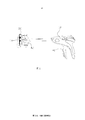
- the stapler includes a body 10, a cartridge assembly 20, an anvil assembly 30, and a firing mechanism, which in turn includes a firing handle/push button 41, a firing handle and a cartridge assembly 20.
- the conventional firing assembly uses a purely mechanical connection, and the firing force is inelastic in use, and the impact is hard.
- the staple forming height is almost the same in a single firing match. But in fact, because the human tissue is not so uniform in thickness, especially in the surgery with a long anastomosis, the thickness of the tissue is more difficult to accurately grasp.
- the staple forming height satisfies the blood-tightening requirement of the thick tissue, it is easy to make the thin tissue part have poor blood-closure effect and cause bleeding, and if the nail forming height is required to meet the blood-tightening requirement of the thin tissue, then For the closure of the thick tissue part, it is easy to be too tight, affecting the blood supply and recovery of the anastomotic site.
- an object of the present invention is to provide a firing assembly for a stapler and a stapler having the same to solve the problem of hardening of the stapler and uneven closure of the staple in the prior art.
- the firing device for a stapler of the present invention comprises:
- a pressure chamber disposed in the component housing and accommodating a fluid
- a push rod disposed under the component housing to provide power, the push rod can push the fluid in the pressure chamber to compress;
- a firing portion that is pushed by the piston A firing portion that is pushed by the piston.
- the present invention also provides an anastomat comprising a stapler body and a firing assembly for the stapler, the stapler firing assembly comprising:
- a pressure chamber disposed in the component housing and accommodating a fluid
- a push rod disposed under the component housing to provide power, the push rod can push the fluid in the pressure chamber to compress;
- a firing portion that is pushed by the piston A firing portion that is pushed by the piston.
- the stapler of the present invention has a soft touch feeling by the firing component, and the staple is closed uniformly and the postoperative effect is good.
- Figure 1 is a partial perspective view of a prior art stapler
- FIG. 2 is a structural view showing an initial state of an embodiment of a firing assembly for a stapler according to the present invention
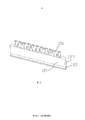
- Figure 3 is a partial perspective view of an embodiment of the firing assembly for a stapler of the present invention, the ratio of which is different from that of Figure 1;
- FIG. 4 is a schematic structural view showing an initial state of firing of a firing assembly for a stapler according to the present invention, wherein an arrow indicates a force at the position;
- Figure 5 is an enlarged view of the area A of Figure 4 showing the difference in the forming height of the staples.
- a firing device 100 for a stapler includes a component housing 101, and guide grooves 1012 and 1014 are formed on both side walls 1011 of the component housing 101.
- the lower portion of the pressure chamber 102 has a booster 103 that is sealingly coupled to the pressure chamber 102.
- Both sides of the booster 103 are housed in the guide grooves 1012 and 1014 and are movable within the guide grooves 1012 and 1014.
- There is a push rod 104 under the booster 103 that can push the booster 103 up to compress the fluid in the pressure chamber 102.
- the purpose of the present invention can also be accomplished if the booster 103 is integrated with the pusher 104.
- the firing assembly further includes a plurality of piston bores 105 in communication with the pressure chamber 102, and a piston 106 is sealingly disposed within the piston bore 105.
- a gasket 107 is disposed between the piston hole 105 and the pressure chamber 102, and a through hole 1071 is formed at a position corresponding to the piston hole 105 on the gasket 107, thereby ensuring communication between the pressure chamber 102 and the piston hole 105.
- the use of the spacer 107 and the through hole 1071 can also be accomplished in other ways, such as providing a blocking member in the piston hole 105.
- the blocking member is not closed, and the fluid pressure in the pressure chamber 102 can be transmitted. To the lower surface of the piston 106 to apply a force to the piston 106.
- firing portion 108 there is a firing portion 108 at the upper portion of the piston 106, and the firing portion 108 on each piston 106 is independently movable in the axial direction of the piston 106.
- the partial or group setting of the firing portion 108 also has the same effect as the independent setting, and can be set according to the specific use situation.
- the pressure in the pressure chamber 102 is the same as the outside, and the piston 106 is in a stationary state.
- the push rod 104 is pushed, and the fluid in the pressure chamber 102 is compressed by the booster 103, so that the pressure of the pressure chamber 102 becomes large, and an upward thrust is generated (as indicated by the arrow in the figure).
- the pressure chamber 102 communicates with the piston hole 105 through the through hole 1071, the pressure inside the piston hole 105 becomes large and pushes the piston 106 upward, thereby causing the firing portion 108 to move up.
- the staple 3 on the firing portion 108 is pushed out and the stapled tissue 2 is fitted and fixed.
- the legs of the staple 3 are bent downward to form a "B" shape by abutting against the anvil 4.
- the forming height of the staples 3 is the same.
- the force of the anastomotic tissue 2 in the staple 3 will also exert a downward thrust on the firing portion 108 (as indicated by the arrow in the figure).
- the reaction force generated by the anastomotic tissue 2 is large, and the fluid is first applied to the piston 106 to act on the firing portion 108.
- the force is balanced, so the staple 3 on the region where the thickness of the anastomosis tissue 2 is large stops deformation.
- the firing portion 108 in the region where the thickness of the anastomotic tissue 2 is small is small because the reaction force generated by the anastomotic tissue 2 is small, and it is not smaller than the force acting on the piston 106 to act on the firing portion 108, so The staple 3 at this point is further deformed to compress the anastomosed tissue 2 until the reaction force on the anastomosed tissue 2 there is balanced with the pressure of the fluid.
- the fluid can transmit the pressure, as long as the area of the piston 106 is the same, the thrust for the firing portion 108 is the same, so that the closing effect of all the anastomotic tissues 2 is the same, but the forming height of the staples 3 is different, please refer to The figure shows.
- the firing assembly of the present invention can be used with a variety of types of staplers, including linear, round tube, and arc-shaped staplers.
- the object of the present invention can be obtained as long as it uses the firing module of the present invention. Since the present invention uses fluid pressure to adjust the difference in the forming height of the staples, the firing action is gentle and ergonomic. In addition, the forming height differs depending on the thickness of the tissue to be stapled, resulting in a final uniform closing effect.
Landscapes
- Health & Medical Sciences (AREA)
- Life Sciences & Earth Sciences (AREA)
- Surgery (AREA)
- Heart & Thoracic Surgery (AREA)
- Engineering & Computer Science (AREA)
- Biomedical Technology (AREA)
- Nuclear Medicine, Radiotherapy & Molecular Imaging (AREA)
- Medical Informatics (AREA)
- Molecular Biology (AREA)
- Animal Behavior & Ethology (AREA)
- General Health & Medical Sciences (AREA)
- Public Health (AREA)
- Veterinary Medicine (AREA)
- Surgical Instruments (AREA)
Abstract
一种吻合器用击发组件(100),包括组件壳体(101);设置于组件壳体(101)内可容纳流体的压力腔(102);设置于组件壳体(101)下以提供动力的推杆(104),推杆(104)可以推动所述压力腔(102)内的流体压缩;与所述压力腔(102)连通的活塞孔(105);容设于所述活塞孔(105)内的活塞(106);通过所述活塞(106)推动的击发部(108)。本吻合器用击发组件(100)击发触感柔和,且吻合钉(3)的闭合均匀。还公开了一种包括该吻合器用击发组件(100)的吻合器。
Description
本申请要求了申请日为2012年12月28日,申请号为CN201210582075.6,发明名称为“吻合器用击发组件及吻合器”的中国专利申请的优先权,其全部内容通过引用结合在本申请中。
【技术领域】
本发明涉及医疗器械技术领域,尤其涉及一种吻合器用击发组件及使用该击发组件的吻合器。
【背景技术】
吻合器用于消化道吻合已近一个世纪,一般分为一次性或多次使用的吻合器,进口或国产吻合器。它是医学上使用的替代传统手工缝合的设备,由于现代科技的发展和制作技术的改进,目前临床上使用的吻合器质量可靠,使用方便,严密、松紧合适,尤其是其缝合快速、操作简便及很少有副作用和手术并发症等优点,有时还使得过去无法切除的肿瘤手术得以病灶切除,很受国内外临床外科医生的青睐和推崇。
一般地,如图1所示,吻合器包括本体10、钉仓组件20、钉砧组件30和击发机构,而击发机构又包括击发把手/推钮41、连接于击发把手和钉仓组件20之间的击发组件42等,传统的击发组件因为使用纯机械式连接,在使用中击发力缺乏弹性,会有击发生硬的感觉。而且,因为受到机构设计的限制,在一次击发吻合中,吻合钉成形高度都几乎相同。但实际上,因为人体组织是厚薄不那么均匀的,尤其是在吻合口较长的手术中,组织的厚薄程度更加难以准确掌握。因此,若吻合钉成型高度满足了厚组织的闭血要求,则容易使较薄组织部分闭血效果不好,而造成出血,而如果想让吻合钉成型高度满足薄组织的闭血要求,则对于厚组织部分的闭合又容易过紧,影响吻合部位的供血、恢复。
因此,需要提供一种能够避免传统吻合器的不利之处的新的击发组件及新型的吻合器。
【发明内容】
为解决上述技术问题,本发明的目的在于提供一种吻合器用击发组件及具有该组件的吻合器以解决现有技术中吻合器击发生硬及钉的闭合不均的问题。
为实现上述发明目的,本发明的吻合器用击发组件,其包括:
组件壳体;
压力腔,设置于所述组件壳体内,并可容纳流体;
推杆;设置于组件壳体下以提供动力,所述推杆可以推动所述压力腔内的流体压缩;
活塞孔,与所述压力腔连通;
活塞,容设于所述活塞孔内;以及
通过所述活塞推动的击发部。
本发明还提供一种吻合器,包括吻合器本体及吻合器用击发组件,所述吻合器用击发组件包括:
组件壳体;
压力腔,设置于所述组件壳体内,并可容纳流体;
推杆;设置于组件壳体下以提供动力,所述推杆可以推动所述压力腔内的流体压缩;
活塞孔,与所述压力腔连通;
活塞,容设于所述活塞孔内;以及
通过所述活塞推动的击发部。
与现有技术相比,本发明的吻合器用击发组件击发触感柔和,且吻合钉的闭合均匀、术后效果好。
【附图说明】
图1为现有技术中吻合器的部分透视图;
图2为本发明吻合器用击发组件的一个实施例的初始状态的结构示图;
图3为本发明吻合器用击发组件的一个实施例的部分立体图,其比例与图1中不同;
图4为本发明吻合器用击发组件的击发初始状态的结构示意图,其中箭头表示在该处的作用力;
图5为图4中A区域的放大图,用以显示吻合钉的成型高度的不同。
【具体实施方式】
下面结合附图所示的各实施方式对本发明进行详细说明,但应当说明的是,这些实施方式并非对本发明的限制,本领域普通技术人员根据这些实施方式所作的功能、方法、或者结构上的等效变换或替代,均属于本发明的保护范围之内。
在本具体实施方式中的描述,如果结合背景技术中的图式及说明更容易理解,但不作为对于本发明的任何限制。且在本发明中,主要的改造在于击发组件的部分,其它部分不作过多描述。
如图2至图5所示,本发明一种吻合器用击发组件100,包括组件壳体101,在组件壳体101的两侧壁1011上开设有引导槽1012及1014。在组件壳体101内还具有压力腔102,所述压力腔102内具有流体,该流体为气体或液体。压力腔102的下部具有助推器103,可与压力腔102密封连接。助推器103的两侧容置于引导槽1012及1014内并可在引导槽1012及1014内移动。在助推器103下具有推杆104,推杆104可以推动助推器103向上运动,从而将压力腔102中的流体压缩。当然,容易理解,如果助推器103与推杆104一体也是可以完成本发明的目的。
该击发组件还包括多个活塞孔105与压力腔102连通,在活塞孔105内密封设置有活塞106。活塞孔105与所述压力腔102之间具有垫片107,在垫片107上对应活塞孔105的位置具有通孔1071,从而保证压力腔102与活塞孔105的连通。当然,垫片107及通孔1071的使用也可以用其它方式来完成,例如在活塞孔105内设置阻挡部件,当然,可以理解,阻挡部件并不闭合,可以使压力腔102中的流体压强传递至活塞106的下表面从而给活塞106施加作用力。
在活塞106的上部具有击发部108,在每个活塞106上的击发部108在活塞106轴向方向上可以独立运动。当然将击发部108中部分独立或成组设置也与独立设置具有同样的效果,可以根据具体的使用情形设定。
本发明在初始状态时,压力腔102内的压强与外界相同,活塞106处于静止状态。在进行击发的过程中,推动推杆104,经过助推器103的作用,将压力腔102内的流体压缩,从而压力腔102的压强变大,产生向上的推力(如图中箭头所示)。因为压力腔102与活塞孔105通过通孔1071进行连通,所以活塞孔105内的压强变大并推动活塞106向上移动,从而带动击发部108上移。于是,将击发部108上的吻合钉3推出并将被吻合组织2吻合、固定。在击发部108向上移动时,吻合钉3的支脚因抵顶于钉砧4上而向下弯折形成“B”型。
在击发部108变形的初期,吻合钉3的成型高度相同。但随着支脚的进一步弯折,吻合钉3内的被吻合组织2受力后也会同样对击发部108产生向下的推力(如图中箭头所示)。此时,对处于被吻合组织2厚度较大的区域的击发部108而言,其因被吻合组织2产生的反作用力较大,较先地与流体作用于活塞106进而作用于击发部108的作用力平衡,所以被吻合组织2厚度较大处的区域上的吻合钉3停止变形。对处于被吻合组织2厚度较小的区域的击发部108而言,其因被吻合组织2产生的反作用力较小,其尚未小于流体作用于活塞106进而作用于击发部108的作用力,所以该处的吻合钉3进一步变形,压紧被吻合组织2,直到该处的被吻合组织2上的反作用力与流体的压力平衡。
根据流体可以传递压强的基本原因,只要活塞106的面积相同,则对于击发部108的推力即相同,从而所有的被吻合组织2的闭合效果相同,但吻合钉3的成型高度不同,请参阅附图所示。
本发明的击发组件可以用于多种类型的吻合器,包括直线型、圆管型、圆弧形吻合器。只要其使用本发明的击发组件,均能够得到本发明的目的。因为本发明采用流体压力来调节吻合钉成型高度的不同,则击发动作柔和,符合人体工学原理,另外,成型高度因被吻合组织的厚度不同而不同,得到最终均匀的闭合效果。
对于本领域技术人员而言,显然本发明不限于上述示范性实施例的细节,而且在不背离本发明的精神或基本特征的情况下,能够以其他的具体形式实现本发明。因此,无论从哪一点来看,均应将实施例看作是示范性的,而且是非限制性的,本发明的范围由所附权利要求而不是上述说明限定,因此旨在将落在权利要求的等同要件的含义和范围内的所有变化囊括在本发明内。不应将权利要求中的任何附图标记视为限制所涉及的权利要求。
此外,应当理解,虽然本说明书按照实施方式加以描述,但并非每个实施方式仅包含一个独立的技术方案,说明书的这种叙述方式仅仅是为清楚起见,本领域技术人员应当将说明书作为一个整体,各实施例中的技术方案也可以经适当组合,形成本领域技术人员可以理解的其他实施方式。
Claims (16)
- 一种吻合器用击发组件,其特征在于,包括:组件壳体;压力腔,设置于所述组件壳体内,并可容纳流体;推杆;设置于组件壳体下以提供动力,所述推杆可以推动所述压力腔内的流体压缩;活塞孔,与所述压力腔连通;活塞,容设于所述活塞孔内;以及通过所述活塞推动的击发部。
- 根据权利要求1所述的吻合器用击发组件,其特征在于,所述压力腔与多个活塞孔相连,多个活塞设置于所述多个活塞孔内,所述活塞上设置有彼此独立的多个击发部。
- 根据权利要求1所述的吻合器用击发组件,其特征在于,所述活塞孔后端具有阻挡部件,以限制所述活塞在所述活塞孔内的运动。
- 根据权利要求3所述的吻合器用击发组件,其特征在于,所述阻挡部件为设置于活塞孔底部的垫片,在所述垫片上对应所述活塞孔部分具有通孔。
- 根据权利要求1所述的吻合器用击发组件,其特征在于,所述压力腔中的流体为液体。
- 根据权利要求1所述的吻合器用击发组件,其特征在于,所述压力腔中的流体为气体。
- 如权利要求1所述的吻合器用击发组件,其特征在于,所述组件壳体的两侧壁上具有引导槽,一助推器设置于所述引导槽中,并通过推杆的作用将所述压力腔中的流体压缩。
- 如权利要求1所述的吻合器用击发组件,其特征在于,所述组件壳体的两侧壁上具有引导槽,所述推杆前端设置有助推器,所述助推器设置于所述引导槽中,可以将所述压力腔中的流体压缩。
- 一种吻合器,包括吻合器本体及吻合器用击发组件,其特征在于,所述吻合器用击发组件包括:组件壳体;压力腔,设置于所述组件壳体内,并可容纳流体;推杆;设置于组件壳体下以提供动力,所述推杆可以推动所述压力腔内的流体压缩;活塞孔,与所述压力腔连通;活塞,容设于所述活塞孔内;以及通过所述活塞推动的击发部。
- 根据权利要求9所述的吻合器,其特征在于,所述压力腔与多个活塞孔相连,多个活塞设置于所述多个活塞孔内,所述活塞上设置有彼此独立的多个击发部。
- 根据权利要求9所述的吻合器,其特征在于,所述活塞孔后端具有阻挡部件,以限制所述活塞在所述活塞孔内的运动。
- 根据权利要求11所述的吻合器,其特征在于,所述阻挡部件为设置于活塞孔底部的垫片,在所述垫片上对应所述活塞孔部分具有通孔。
- 根据权利要求9所述的吻合器,其特征在于,所述压力腔中的流体为液体。
- 根据权利要求1所述的吻合器,其特征在于,所述压力腔中的流体为气体。
- 如权利要求1所述的吻合器,其特征在于,所述组件壳体的两侧壁上具有引导槽,一助推器设置于所述引导槽中,并通过推杆的作用将所述压力腔中的流体压缩。
- 如权利要求1所述的吻合器,其特征在于,所述组件壳体的两侧壁上具有引导槽,所述推杆前端设置有助推器,所述助推器设置于所述引导槽中,可以将所述压力腔中的流体压缩。
Priority Applications (4)
| Application Number | Priority Date | Filing Date | Title |
|---|---|---|---|
| ES13866753T ES2802818T3 (es) | 2012-12-28 | 2013-12-26 | Componente de disparo de uso en grapadora y grapadora |
| JP2015545657A JP6117934B2 (ja) | 2012-12-28 | 2013-12-26 | ステープラ用コッキングアセンブリ及びステープラ |
| EP13866753.0A EP2942017B1 (en) | 2012-12-28 | 2013-12-26 | Stapler-use firing component and stapler |
| US14/750,645 US9888923B2 (en) | 2012-12-28 | 2015-06-25 | Firing assembly for surgical stapler and surgical stapler |
Applications Claiming Priority (2)
| Application Number | Priority Date | Filing Date | Title |
|---|---|---|---|
| CN201210582075.6A CN103142269B (zh) | 2012-12-28 | 2012-12-28 | 吻合器用击发组件及吻合器 |
| CN201210582075.6 | 2012-12-28 |
Related Child Applications (1)
| Application Number | Title | Priority Date | Filing Date |
|---|---|---|---|
| US14/750,645 Continuation US9888923B2 (en) | 2012-12-28 | 2015-06-25 | Firing assembly for surgical stapler and surgical stapler |
Publications (1)
| Publication Number | Publication Date |
|---|---|
| WO2014101794A1 true WO2014101794A1 (zh) | 2014-07-03 |
Family
ID=48540812
Family Applications (1)
| Application Number | Title | Priority Date | Filing Date |
|---|---|---|---|
| PCT/CN2013/090561 Ceased WO2014101794A1 (zh) | 2012-12-28 | 2013-12-26 | 吻合器用击发组件及吻合器 |
Country Status (7)
| Country | Link |
|---|---|
| US (1) | US9888923B2 (zh) |
| EP (1) | EP2942017B1 (zh) |
| JP (1) | JP6117934B2 (zh) |
| CN (1) | CN103142269B (zh) |
| ES (1) | ES2802818T3 (zh) |
| HU (1) | HUE051449T2 (zh) |
| WO (1) | WO2014101794A1 (zh) |
Families Citing this family (17)
| Publication number | Priority date | Publication date | Assignee | Title |
|---|---|---|---|---|
| CN103142269B (zh) * | 2012-12-28 | 2014-12-17 | 苏州天臣国际医疗科技有限公司 | 吻合器用击发组件及吻合器 |
| US11166715B2 (en) | 2019-05-13 | 2021-11-09 | Cilag Gmbh International | Actuator support structure for surgical stapler |
| WO2021022407A1 (en) | 2019-08-02 | 2021-02-11 | Covidien Lp | Surgical stapling device with curved tool assembly |
| CN114727818A (zh) | 2019-11-01 | 2022-07-08 | 柯惠有限合伙公司 | 带有刀片锁的外科钉合装置 |
| CN114845646A (zh) | 2019-12-18 | 2022-08-02 | 柯惠有限合伙公司 | 具有装运盖的手术钉合装置 |
| CN111053587B (zh) * | 2019-12-31 | 2024-12-24 | 重庆迈科唯医疗科技有限公司 | 一段式推进、回退装置及吻合器 |
| EP4099916A4 (en) | 2020-02-03 | 2024-01-17 | Covidien LP | TISSUE GUIDE FOR CURVED END EFFECTORS |
| WO2021159475A1 (en) | 2020-02-14 | 2021-08-19 | Covidien Lp | Surgical stapling device with disposable cutting plate |
| US12318088B2 (en) | 2020-02-27 | 2025-06-03 | Covidien Lp | Surgical stapling device with reloadable cartridge |
| EP4110194A4 (en) | 2020-02-28 | 2023-11-29 | Covidien LP | CLAP CARTRIDGE WITH RETRACTABLE BLADE ARRANGEMENT |
| US11744584B2 (en) | 2020-06-09 | 2023-09-05 | Covidien Lp | Alignment pin assembly for surgical stapler |
| CN112617927B (zh) * | 2020-12-11 | 2022-02-08 | 苏州法兰克曼医疗器械有限公司 | 一种防止误操作的新型吻合器 |
| JP2023554080A (ja) | 2020-12-17 | 2023-12-26 | コヴィディエン リミテッド パートナーシップ | 湾曲エンドエフェクタを有するステープル留め装置 |
| WO2022178758A1 (en) | 2021-02-25 | 2022-09-01 | Covidien Lp | Anvil assembly with reduced deflection |
| EP4312811A1 (en) | 2021-03-30 | 2024-02-07 | Covidien LP | Surgical stapling device including a loading unit alignment indicator |
| WO2022233014A1 (en) | 2021-05-07 | 2022-11-10 | Covidien Lp | End effector for surgical stapling device |
| US12268390B2 (en) | 2021-07-19 | 2025-04-08 | Covidien Lp | Stapling device with replaceable cartridge module |
Citations (6)
| Publication number | Priority date | Publication date | Assignee | Title |
|---|---|---|---|---|
| US4621639A (en) * | 1982-02-03 | 1986-11-11 | Ethicon, Inc | Surgical instrument with hydraulic actuator |
| US20080110958A1 (en) * | 2006-11-10 | 2008-05-15 | Mckenna Robert H | Disposable Cartridge With Adhesive For Use With A Stapling Device |
| CN101305928A (zh) * | 2007-05-15 | 2008-11-19 | 施峻 | 消化道管型吻合器 |
| CN101534725A (zh) * | 2006-09-29 | 2009-09-16 | 伊西康内外科公司 | 带有自调节砧座的外科切割和缝合器械 |
| CN103142269A (zh) * | 2012-12-28 | 2013-06-12 | 苏州天臣国际医疗科技有限公司 | 吻合器用击发组件及吻合器 |
| CN203029297U (zh) * | 2012-12-28 | 2013-07-03 | 苏州天臣国际医疗科技有限公司 | 吻合器用击发组件及吻合器 |
Family Cites Families (41)
| Publication number | Priority date | Publication date | Assignee | Title |
|---|---|---|---|---|
| US3888003A (en) * | 1974-07-12 | 1975-06-10 | Frank R Brown | Power handle for pivotally interconnected lever tools |
| US4331277A (en) * | 1980-05-23 | 1982-05-25 | United States Surgical Corporation | Self-contained gas powered surgical stapler |
| US4586502A (en) * | 1982-02-03 | 1986-05-06 | Ethicon, Inc. | Surgical instrument actuator with non-collinear hydraulic pistons |
| GB8800909D0 (en) * | 1988-01-15 | 1988-02-17 | Ethicon Inc | Gas powered surgical stapler |
| ES2011110A6 (es) * | 1988-09-02 | 1989-12-16 | Lopez Hervas Pedro | Aparato hidraulico de cuerpo flexible para anastomosis quirurgicas. |
| US4930674A (en) * | 1989-02-24 | 1990-06-05 | Abiomed, Inc. | Surgical stapler |
| US5005754A (en) * | 1990-04-04 | 1991-04-09 | Ethicon, Inc. | Bladder and mandrel for use with surgical stapler |
| US5163598A (en) * | 1990-07-23 | 1992-11-17 | Rudolph Peters | Sternum stapling apparatus |
| US5219111A (en) * | 1991-03-11 | 1993-06-15 | Ethicon, Inc. | Pneumatically actuated linear stapling device |
| US5197649A (en) * | 1991-10-29 | 1993-03-30 | The Trustees Of Columbia University In The City Of New York | Gastrointestinal endoscoptic stapler |
| US5658300A (en) * | 1992-06-04 | 1997-08-19 | Olympus Optical Co., Ltd. | Tissue fixing surgical instrument, tissue-fixing device, and method of fixing tissues |
| JPH0647050A (ja) * | 1992-06-04 | 1994-02-22 | Olympus Optical Co Ltd | 組織縫合結紮器 |
| CA2117744A1 (en) * | 1993-10-14 | 1995-04-15 | David T. Green | Gas powered apparatus for applying surgical fasteners to body tissue |
| WO1995018572A1 (en) * | 1994-01-04 | 1995-07-13 | Alpha Surgical Technologies, Inc. | Stapling device |
| US5833695A (en) * | 1994-07-13 | 1998-11-10 | Yoon; Inbae | Surgical stapling system and method of applying staples from multiple staple cartridges |
| US5533521A (en) * | 1994-07-15 | 1996-07-09 | United States Surgical Corporation | Interchangeable tissue measuring device |
| US5868760A (en) * | 1994-12-07 | 1999-02-09 | Mcguckin, Jr.; James F. | Method and apparatus for endolumenally resectioning tissue |
| US6387113B1 (en) * | 1999-02-02 | 2002-05-14 | Biomet, Inc. | Method and apparatus for repairing a torn meniscus |
| US6716233B1 (en) * | 1999-06-02 | 2004-04-06 | Power Medical Interventions, Inc. | Electromechanical driver and remote surgical instrument attachment having computer assisted control capabilities |
| US7695485B2 (en) * | 2001-11-30 | 2010-04-13 | Power Medical Interventions, Llc | Surgical device |
| US6491201B1 (en) * | 2000-02-22 | 2002-12-10 | Power Medical Interventions, Inc. | Fluid delivery mechanism for use with anastomosing, stapling, and resecting instruments |
| US6911032B2 (en) * | 1999-11-18 | 2005-06-28 | Scimed Life Systems, Inc. | Apparatus and method for compressing body tissue |
| US8287561B2 (en) * | 2002-06-28 | 2012-10-16 | Boston Scientific Scimed, Inc. | Balloon-type actuator for surgical applications |
| WO2004032760A2 (en) * | 2002-10-04 | 2004-04-22 | Tyco Healthcare Group, Lp | Pneumatic powered surgical stapling device |
| CA2519461C (en) * | 2003-03-26 | 2012-05-29 | Tyco Healthcare Group Lp | Energy stored in spring with controlled release |
| US7766207B2 (en) * | 2003-12-30 | 2010-08-03 | Ethicon Endo-Surgery, Inc. | Articulating curved cutter stapler |
| US8579178B2 (en) * | 2005-08-15 | 2013-11-12 | Covidien Lp | Surgical stapling instruments including a cartridge having multiple staples sizes |
| US7472815B2 (en) * | 2005-09-21 | 2009-01-06 | Ethicon Endo-Surgery, Inc. | Surgical stapling instruments with collapsible features for controlling staple height |
| US7799039B2 (en) * | 2005-11-09 | 2010-09-21 | Ethicon Endo-Surgery, Inc. | Surgical instrument having a hydraulically actuated end effector |
| US20070106317A1 (en) * | 2005-11-09 | 2007-05-10 | Shelton Frederick E Iv | Hydraulically and electrically actuated articulation joints for surgical instruments |
| US7434716B2 (en) * | 2006-12-21 | 2008-10-14 | Tyco Healthcare Group Lp | Staple driver for articulating surgical stapler |
| US9421006B2 (en) * | 2007-01-08 | 2016-08-23 | Endogastric Solutions, Inc. | Connected fasteners, delivery device and method |
| US8893946B2 (en) * | 2007-03-28 | 2014-11-25 | Ethicon Endo-Surgery, Inc. | Laparoscopic tissue thickness and clamp load measuring devices |
| US9016541B2 (en) * | 2008-05-09 | 2015-04-28 | Covidien Lp | Varying tissue compression with an anvil configuration |
| US8016176B2 (en) * | 2008-06-04 | 2011-09-13 | Tyco Healthcare Group, Lp | Surgical stapling instrument with independent sequential firing |
| US7934631B2 (en) * | 2008-11-10 | 2011-05-03 | Barosense, Inc. | Multi-fire stapling systems and methods for delivering arrays of staples |
| US8955732B2 (en) * | 2009-08-11 | 2015-02-17 | Covidien Lp | Surgical stapling apparatus |
| US8348127B2 (en) * | 2010-04-07 | 2013-01-08 | Covidien Lp | Surgical fastener applying apparatus |
| US8491526B2 (en) * | 2010-05-13 | 2013-07-23 | Ethicon Endo-Surgery, Inc. | Therapeutic cell applicator instrument with modular tips |
| US8596515B2 (en) * | 2010-06-18 | 2013-12-03 | Covidien Lp | Staple position sensor system |
| US9597074B2 (en) * | 2013-08-15 | 2017-03-21 | Ethicon Endo-Surgery, Llc | Endoluminal stapler with rotating wheel cam for multi-staple firing |
-
2012
- 2012-12-28 CN CN201210582075.6A patent/CN103142269B/zh active Active
-
2013
- 2013-12-26 JP JP2015545657A patent/JP6117934B2/ja active Active
- 2013-12-26 EP EP13866753.0A patent/EP2942017B1/en active Active
- 2013-12-26 HU HUE13866753A patent/HUE051449T2/hu unknown
- 2013-12-26 WO PCT/CN2013/090561 patent/WO2014101794A1/zh not_active Ceased
- 2013-12-26 ES ES13866753T patent/ES2802818T3/es active Active
-
2015
- 2015-06-25 US US14/750,645 patent/US9888923B2/en not_active Expired - Fee Related
Patent Citations (6)
| Publication number | Priority date | Publication date | Assignee | Title |
|---|---|---|---|---|
| US4621639A (en) * | 1982-02-03 | 1986-11-11 | Ethicon, Inc | Surgical instrument with hydraulic actuator |
| CN101534725A (zh) * | 2006-09-29 | 2009-09-16 | 伊西康内外科公司 | 带有自调节砧座的外科切割和缝合器械 |
| US20080110958A1 (en) * | 2006-11-10 | 2008-05-15 | Mckenna Robert H | Disposable Cartridge With Adhesive For Use With A Stapling Device |
| CN101305928A (zh) * | 2007-05-15 | 2008-11-19 | 施峻 | 消化道管型吻合器 |
| CN103142269A (zh) * | 2012-12-28 | 2013-06-12 | 苏州天臣国际医疗科技有限公司 | 吻合器用击发组件及吻合器 |
| CN203029297U (zh) * | 2012-12-28 | 2013-07-03 | 苏州天臣国际医疗科技有限公司 | 吻合器用击发组件及吻合器 |
Also Published As
| Publication number | Publication date |
|---|---|
| EP2942017B1 (en) | 2020-05-13 |
| EP2942017A4 (en) | 2016-09-28 |
| JP2016504074A (ja) | 2016-02-12 |
| CN103142269A (zh) | 2013-06-12 |
| US20150289871A1 (en) | 2015-10-15 |
| JP6117934B2 (ja) | 2017-04-19 |
| CN103142269B (zh) | 2014-12-17 |
| US9888923B2 (en) | 2018-02-13 |
| ES2802818T3 (es) | 2021-01-21 |
| HUE051449T2 (hu) | 2021-03-29 |
| EP2942017A1 (en) | 2015-11-11 |
Similar Documents
| Publication | Publication Date | Title |
|---|---|---|
| WO2014101794A1 (zh) | 吻合器用击发组件及吻合器 | |
| US12059150B2 (en) | Surgical stapling and cutting device | |
| WO2020168485A1 (zh) | 具有两种激发形式的活检针 | |
| CN107802302A (zh) | 一种手术用吻合器装置 | |
| CN114869430B (zh) | 房间隔穿刺系统 | |
| CN108378885B (zh) | 一种具有空钉仓安全保险装置的外科吻合器钉仓组件 | |
| CN203417225U (zh) | 电动外科装订器械 | |
| CN105411640B (zh) | 钉仓组件及使用该钉仓组件的医用吻合器 | |
| WO2014094558A1 (zh) | 钉头组件以及应用该钉头组件的直线缝切器 | |
| CN220025109U (zh) | 手术器械 | |
| CN114533159B (zh) | 一种缓冲驱动装置及电动缝合器 | |
| CN209644987U (zh) | 击发机构及吻合器 | |
| CN107242889B (zh) | 一种荷包缝合切割闭合器 | |
| CN203029304U (zh) | 指针件及设有该指针件的圆管型吻合器 | |
| CN211213310U (zh) | 一种外科缝合器的钉砧组件和装载单元、以及外科缝合器 | |
| CN219250305U (zh) | 一种推钉式鼻中隔吻合器 | |
| CN209091489U (zh) | 一种具有空钉仓安全保险装置的外科吻合器钉仓组件 | |
| CN203029297U (zh) | 吻合器用击发组件及吻合器 | |
| CN101926664A (zh) | 适用于食道高位手术的圆管型装订仪 | |
| CN219501012U (zh) | 一体式血糖采集笔 | |
| CN112603415A (zh) | 一种快捷式吻合器 | |
| CN223731437U (zh) | 一种吻合器钉匣底座 | |
| CN115804625B (zh) | 一种推钉式鼻中隔吻合器 | |
| CN219166512U (zh) | 一种具有空钉仓安全保险装置的吻合器钉仓组件 | |
| CN213665468U (zh) | 一种横向腔内缝合器 |
Legal Events
| Date | Code | Title | Description |
|---|---|---|---|
| 121 | Ep: the epo has been informed by wipo that ep was designated in this application |
Ref document number: 13866753 Country of ref document: EP Kind code of ref document: A1 |
|
| ENP | Entry into the national phase |
Ref document number: 2015545657 Country of ref document: JP Kind code of ref document: A |
|
| NENP | Non-entry into the national phase |
Ref country code: DE |
|
| WWE | Wipo information: entry into national phase |
Ref document number: 2013866753 Country of ref document: EP |