WO2014102934A1 - ヒートポンプ温水暖房機 - Google Patents
ヒートポンプ温水暖房機 Download PDFInfo
- Publication number
- WO2014102934A1 WO2014102934A1 PCT/JP2012/083692 JP2012083692W WO2014102934A1 WO 2014102934 A1 WO2014102934 A1 WO 2014102934A1 JP 2012083692 W JP2012083692 W JP 2012083692W WO 2014102934 A1 WO2014102934 A1 WO 2014102934A1
- Authority
- WO
- WIPO (PCT)
- Prior art keywords
- water
- heat exchanger
- refrigerant
- circuit
- heat
- Prior art date
- Legal status (The legal status is an assumption and is not a legal conclusion. Google has not performed a legal analysis and makes no representation as to the accuracy of the status listed.)
- Ceased
Links
Images


Classifications
-
- F—MECHANICAL ENGINEERING; LIGHTING; HEATING; WEAPONS; BLASTING
- F25—REFRIGERATION OR COOLING; COMBINED HEATING AND REFRIGERATION SYSTEMS; HEAT PUMP SYSTEMS; MANUFACTURE OR STORAGE OF ICE; LIQUEFACTION SOLIDIFICATION OF GASES
- F25B—REFRIGERATION MACHINES, PLANTS OR SYSTEMS; COMBINED HEATING AND REFRIGERATION SYSTEMS; HEAT PUMP SYSTEMS
- F25B47/00—Arrangements for preventing or removing deposits or corrosion, not provided for in another subclass
- F25B47/02—Defrosting cycles
- F25B47/022—Defrosting cycles hot gas defrosting
- F25B47/025—Defrosting cycles hot gas defrosting by reversing the cycle
-
- F—MECHANICAL ENGINEERING; LIGHTING; HEATING; WEAPONS; BLASTING
- F24—HEATING; RANGES; VENTILATING
- F24D—DOMESTIC- OR SPACE-HEATING SYSTEMS, e.g. CENTRAL HEATING SYSTEMS; DOMESTIC HOT-WATER SUPPLY SYSTEMS; ELEMENTS OR COMPONENTS THEREFOR
- F24D11/00—Central heating systems using heat accumulated in storage masses
- F24D11/02—Central heating systems using heat accumulated in storage masses using heat pumps
- F24D11/0214—Central heating systems using heat accumulated in storage masses using heat pumps water heating system
-
- F—MECHANICAL ENGINEERING; LIGHTING; HEATING; WEAPONS; BLASTING
- F24—HEATING; RANGES; VENTILATING
- F24D—DOMESTIC- OR SPACE-HEATING SYSTEMS, e.g. CENTRAL HEATING SYSTEMS; DOMESTIC HOT-WATER SUPPLY SYSTEMS; ELEMENTS OR COMPONENTS THEREFOR
- F24D19/00—Details
- F24D19/0095—Devices for preventing damage by freezing
-
- F—MECHANICAL ENGINEERING; LIGHTING; HEATING; WEAPONS; BLASTING
- F24—HEATING; RANGES; VENTILATING
- F24D—DOMESTIC- OR SPACE-HEATING SYSTEMS, e.g. CENTRAL HEATING SYSTEMS; DOMESTIC HOT-WATER SUPPLY SYSTEMS; ELEMENTS OR COMPONENTS THEREFOR
- F24D19/00—Details
- F24D19/10—Arrangement or mounting of control or safety devices
- F24D19/1006—Arrangement or mounting of control or safety devices for water heating systems
- F24D19/1009—Arrangement or mounting of control or safety devices for water heating systems for central heating
- F24D19/1039—Arrangement or mounting of control or safety devices for water heating systems for central heating the system uses a heat pump
-
- F—MECHANICAL ENGINEERING; LIGHTING; HEATING; WEAPONS; BLASTING
- F24—HEATING; RANGES; VENTILATING
- F24H—FLUID HEATERS, e.g. WATER OR AIR HEATERS, HAVING HEAT-GENERATING MEANS, e.g. HEAT PUMPS, IN GENERAL
- F24H15/00—Control of fluid heaters
- F24H15/10—Control of fluid heaters characterised by the purpose of the control
- F24H15/136—Defrosting or de-icing; Preventing freezing
-
- F—MECHANICAL ENGINEERING; LIGHTING; HEATING; WEAPONS; BLASTING
- F24—HEATING; RANGES; VENTILATING
- F24H—FLUID HEATERS, e.g. WATER OR AIR HEATERS, HAVING HEAT-GENERATING MEANS, e.g. HEAT PUMPS, IN GENERAL
- F24H15/00—Control of fluid heaters
- F24H15/20—Control of fluid heaters characterised by control inputs
- F24H15/212—Temperature of the water
- F24H15/215—Temperature of the water before heating
-
- F—MECHANICAL ENGINEERING; LIGHTING; HEATING; WEAPONS; BLASTING
- F24—HEATING; RANGES; VENTILATING
- F24H—FLUID HEATERS, e.g. WATER OR AIR HEATERS, HAVING HEAT-GENERATING MEANS, e.g. HEAT PUMPS, IN GENERAL
- F24H15/00—Control of fluid heaters
- F24H15/20—Control of fluid heaters characterised by control inputs
- F24H15/254—Room temperature
-
- F—MECHANICAL ENGINEERING; LIGHTING; HEATING; WEAPONS; BLASTING
- F24—HEATING; RANGES; VENTILATING
- F24H—FLUID HEATERS, e.g. WATER OR AIR HEATERS, HAVING HEAT-GENERATING MEANS, e.g. HEAT PUMPS, IN GENERAL
- F24H15/00—Control of fluid heaters
- F24H15/30—Control of fluid heaters characterised by control outputs; characterised by the components to be controlled
- F24H15/375—Control of heat pumps
- F24H15/38—Control of compressors of heat pumps
-
- F—MECHANICAL ENGINEERING; LIGHTING; HEATING; WEAPONS; BLASTING
- F25—REFRIGERATION OR COOLING; COMBINED HEATING AND REFRIGERATION SYSTEMS; HEAT PUMP SYSTEMS; MANUFACTURE OR STORAGE OF ICE; LIQUEFACTION SOLIDIFICATION OF GASES
- F25B—REFRIGERATION MACHINES, PLANTS OR SYSTEMS; COMBINED HEATING AND REFRIGERATION SYSTEMS; HEAT PUMP SYSTEMS
- F25B30/00—Heat pumps
- F25B30/02—Heat pumps of the compression type
-
- F—MECHANICAL ENGINEERING; LIGHTING; HEATING; WEAPONS; BLASTING
- F25—REFRIGERATION OR COOLING; COMBINED HEATING AND REFRIGERATION SYSTEMS; HEAT PUMP SYSTEMS; MANUFACTURE OR STORAGE OF ICE; LIQUEFACTION SOLIDIFICATION OF GASES
- F25B—REFRIGERATION MACHINES, PLANTS OR SYSTEMS; COMBINED HEATING AND REFRIGERATION SYSTEMS; HEAT PUMP SYSTEMS
- F25B49/00—Arrangement or mounting of control or safety devices
- F25B49/02—Arrangement or mounting of control or safety devices for compression type machines, plants or systems
-
- F—MECHANICAL ENGINEERING; LIGHTING; HEATING; WEAPONS; BLASTING
- F24—HEATING; RANGES; VENTILATING
- F24D—DOMESTIC- OR SPACE-HEATING SYSTEMS, e.g. CENTRAL HEATING SYSTEMS; DOMESTIC HOT-WATER SUPPLY SYSTEMS; ELEMENTS OR COMPONENTS THEREFOR
- F24D2200/00—Heat sources or energy sources
- F24D2200/12—Heat pump
- F24D2200/123—Compression type heat pumps
-
- F—MECHANICAL ENGINEERING; LIGHTING; HEATING; WEAPONS; BLASTING
- F25—REFRIGERATION OR COOLING; COMBINED HEATING AND REFRIGERATION SYSTEMS; HEAT PUMP SYSTEMS; MANUFACTURE OR STORAGE OF ICE; LIQUEFACTION SOLIDIFICATION OF GASES
- F25B—REFRIGERATION MACHINES, PLANTS OR SYSTEMS; COMBINED HEATING AND REFRIGERATION SYSTEMS; HEAT PUMP SYSTEMS
- F25B2339/00—Details of evaporators; Details of condensers
- F25B2339/04—Details of condensers
- F25B2339/047—Water-cooled condensers
-
- F—MECHANICAL ENGINEERING; LIGHTING; HEATING; WEAPONS; BLASTING
- F25—REFRIGERATION OR COOLING; COMBINED HEATING AND REFRIGERATION SYSTEMS; HEAT PUMP SYSTEMS; MANUFACTURE OR STORAGE OF ICE; LIQUEFACTION SOLIDIFICATION OF GASES
- F25B—REFRIGERATION MACHINES, PLANTS OR SYSTEMS; COMBINED HEATING AND REFRIGERATION SYSTEMS; HEAT PUMP SYSTEMS
- F25B2600/00—Control issues
- F25B2600/01—Timing
-
- F—MECHANICAL ENGINEERING; LIGHTING; HEATING; WEAPONS; BLASTING
- F25—REFRIGERATION OR COOLING; COMBINED HEATING AND REFRIGERATION SYSTEMS; HEAT PUMP SYSTEMS; MANUFACTURE OR STORAGE OF ICE; LIQUEFACTION SOLIDIFICATION OF GASES
- F25B—REFRIGERATION MACHINES, PLANTS OR SYSTEMS; COMBINED HEATING AND REFRIGERATION SYSTEMS; HEAT PUMP SYSTEMS
- F25B2700/00—Sensing or detecting of parameters; Sensors therefor
- F25B2700/21—Temperatures
- F25B2700/2116—Temperatures of a condenser
- F25B2700/21161—Temperatures of a condenser of the fluid heated by the condenser
-
- F—MECHANICAL ENGINEERING; LIGHTING; HEATING; WEAPONS; BLASTING
- F25—REFRIGERATION OR COOLING; COMBINED HEATING AND REFRIGERATION SYSTEMS; HEAT PUMP SYSTEMS; MANUFACTURE OR STORAGE OF ICE; LIQUEFACTION SOLIDIFICATION OF GASES
- F25B—REFRIGERATION MACHINES, PLANTS OR SYSTEMS; COMBINED HEATING AND REFRIGERATION SYSTEMS; HEAT PUMP SYSTEMS
- F25B2700/00—Sensing or detecting of parameters; Sensors therefor
- F25B2700/21—Temperatures
- F25B2700/2117—Temperatures of an evaporator
- F25B2700/21171—Temperatures of an evaporator of the fluid cooled by the evaporator
Definitions
- the present invention relates to a heat pump hot water heater.
- Patent Document 1 Japanese Unexamined Patent Application Publication No. 2010-181104 discloses a water heater that is a heat pump device including a refrigerant circuit and a water circuit.
- the refrigerant circuit is a circuit that includes a compressor, an outdoor heat exchanger, and an indoor heat exchanger, and circulates the refrigerant.
- the water circuit is a circuit through which water flows while sharing the refrigerant circuit and the indoor heat exchanger.
- the high-temperature refrigerant compressed by the compressor is cooled by exchanging heat with water in the indoor heat exchanger, and after being depressurized, it is heated by exchanging heat with the outside air in the outdoor heat exchanger.
- the water flowing through the water circuit is heated by exchanging heat with the refrigerant in the indoor heat exchanger.
- frost adheres to the outdoor heat exchanger and the operating efficiency decreases when the temperature of the outside air is low.
- the heat pump device performs a defrost operation for melting frost attached to the outdoor heat exchanger.
- the heat pump device performs reverse cycle operation in which the refrigerant circulation direction in the refrigerant circuit is reversed from that during normal operation.
- coolant compressed with the compressor flows in into an outdoor heat exchanger, and defrost (defrost) of an outdoor heat exchanger is performed.
- Patent Literature 1 discloses a heat pump device that performs defrosting by reverse cycle operation after flowing hot water in a hot water storage tank connected to a water circuit to an indoor heat exchanger and accumulating heat in the indoor heat exchanger. Has been.
- Patent Document 2 International Publication No.
- 2006/103815 discloses a mode in which defrosting is performed by reverse cycle operation using the heat of hot water remaining in the water circuit, and a high temperature discharged from the compressor of the refrigerant circuit.
- the heat pump device has a mode in which the refrigerant is passed through the outdoor heat exchanger and the refrigerant that has passed through the outdoor heat exchanger is returned to the compressor as it is to perform defrosting.
- An object of the present invention is to provide a heat pump hot water heater capable of preventing freezing of water.
- the heat pump hot water heater includes a refrigerant circuit, a water circuit, and a control unit.
- the refrigerant circuit is a circuit through which the refrigerant circulates.
- the refrigerant circuit includes a first heat exchanger that exchanges heat between the air and the refrigerant, a second heat exchanger that exchanges heat between the refrigerant and water, and a compressor that compresses the refrigerant.
- the water circuit is a circuit through which water flows.
- the water circuit includes a second heat exchanger and a water supply mechanism that supplies water to the second heat exchanger.
- the control unit controls the refrigerant circuit and the water circuit in order to perform the defrost operation of the first heat exchanger.
- the refrigerant circuit can switch between a normal cycle operation and a reverse cycle operation.
- the refrigerant circulates in the order of the compressor, the second heat exchanger, the first heat exchanger, and the compressor.
- the reverse cycle operation the refrigerant circulates in the order of the compressor, the first heat exchanger, the second heat exchanger, and the compressor.
- the control unit performs forward cycle operation or reverse cycle operation by determining the possibility of water freezing in the water circuit at least at the start of defrost operation and at the time of execution of defrost operation. Select and perform defrost operation.
- This heat pump hot water heater is a heat pump device including a refrigerant circuit and a water circuit sharing the second heat exchanger.
- the high-temperature refrigerant compressed by the refrigerant circuit compressor is heat-exchanged with the water flowing through the water circuit in the second heat exchanger.
- heat is transferred from the refrigerant flowing through the refrigerant circuit to the water flowing through the water circuit.
- the control unit can switch between the normal cycle operation and the reverse cycle operation by controlling the refrigerant circuit.
- the high-temperature refrigerant compressed by the compressor flows into the second heat exchanger, and in the reverse cycle operation, the high-temperature refrigerant compressed by the compressor flows into the first heat exchanger.
- frost may adhere under the conditions where the temperature of outside air is low.
- the heat pump hot water heater performs a defrost operation for removing frost attached to the first heat exchanger.
- the control unit normally performs defrost operation by reverse cycle operation. However, when it is determined that the water flowing through the water circuit may be frozen by performing the defrost operation by the reverse cycle operation, the control unit performs the defrost operation by the normal cycle operation.
- the defrost operation by the normal cycle operation is performed by stopping the operation of the water supply mechanism of the water circuit and increasing the opening degree of the expansion mechanism of the refrigerant circuit.
- By stopping the water supply mechanism heat exchange in the second heat exchanger is suppressed, and heat is accumulated in the second heat exchanger.
- By increasing the opening degree of the expansion mechanism the heat of the compressor and the second heat exchanger is transmitted to the first heat exchanger via the refrigerant and the expansion mechanism. Thereby, the 1st heat exchanger is heated and the frost adhering to the 1st heat exchanger is removed.
- This heat pump hot water heater selects and executes either the defrost operation by the normal cycle operation or the defrost operation by the reverse cycle operation based on the possibility of freezing of the water flowing through the water circuit.
- the defrost operation by the reverse cycle operation the high-temperature refrigerant compressed by the compressor directly flows into the first heat exchanger, so that frost attached to the first heat exchanger is efficiently removed.
- the second heat exchanger heat exchange is performed in which heat is transferred from the water flowing in the water circuit to the refrigerant flowing in the refrigerant circuit, so that the water in the water circuit is frozen when the temperature of the water in the water circuit is low. As a result, the water circuit may be destroyed.
- the heat pump hot water heater according to the second aspect of the present invention is the heat pump hot water heater according to the first aspect, and the controller is configured to control the temperature of water flowing into the second heat exchanger at the start of the defrost operation.
- the controller is configured to control the temperature of water flowing into the second heat exchanger at the start of the defrost operation.
- the temperature is equal to or lower than the first temperature, it is selected to perform the positive cycle operation, and the operation of the water supply mechanism is stopped.
- the heat pump hot water heater selects and executes either the defrost operation by the normal cycle operation or the defrost operation by the reverse cycle operation at the start of the defrost operation.
- a control part judges that the water which flows through a water circuit may be frozen by performing defrost operation by reverse cycle operation, when the temperature of the water which flows into the 2nd heat exchanger is below predetermined temperature. . In this case, this heat pump hot water heater starts the defrost operation by the normal cycle operation.
- the heat pump hot water heater according to the third aspect of the present invention is the heat pump hot water heater according to the first aspect or the second aspect, and the control unit performs heat exchange with the first heat exchanger at the start of the defrost operation.
- the normal cycle operation is selected and the operation of the water supply mechanism is stopped.
- the heat pump hot water heater selects and executes either the defrost operation by the normal cycle operation or the defrost operation by the reverse cycle operation at the start of the defrost operation.
- the control unit may freeze the water flowing through the water circuit by performing the defrost operation by the reverse cycle operation. to decide. In this case, this heat pump hot water heater starts the defrost operation by the normal cycle operation.
- a heat pump hot water heater is the heat pump hot water heater according to any of the first to third aspects, wherein the control unit is configured to start the defrost operation before starting the defrost operation.
- the control unit is configured to start the defrost operation before starting the defrost operation.
- the normal cycle operation is selected and the operation of the water supply mechanism is stopped.
- the heat pump hot water heater selects and executes either the defrost operation by the normal cycle operation or the defrost operation by the reverse cycle operation at the start of the defrost operation.
- the control unit performs the defrost operation by the reverse cycle operation when the stop time of the normal operation for heating the water of the water circuit by the normal cycle operation is a predetermined time or more. Judge that the flowing water may freeze. In this case, this heat pump hot water heater starts the defrost operation by the normal cycle operation.
- a heat pump hot water heater is the heat pump hot water heater according to any one of the first aspect to the fourth aspect, and the control unit performs the previous defrost operation at the start of the defrost operation.
- the execution time is equal to or shorter than the second time, it is selected to perform the normal cycle operation, and the operation of the water supply mechanism is stopped.
- the heat pump hot water heater selects and executes either the defrost operation by the normal cycle operation or the defrost operation by the reverse cycle operation at the start of the defrost operation.
- a control part judges that the water which flows through a water circuit may freeze by performing defrost operation by reverse cycle operation, when the execution time of the last defrost operation is below predetermined time. In this case, this heat pump hot water heater starts the defrost operation by the normal cycle operation.
- a heat pump hot water heater is the heat pump hot water heater according to any one of the first aspect to the fifth aspect, wherein the controller is configured to perform the defrosting operation by the reverse cycle operation. 2
- the controller is configured to perform the defrosting operation by the reverse cycle operation. 2
- the temperature of the water flowing into the heat exchanger is equal to or lower than the third temperature, it is selected to perform the normal cycle operation, and the operation of the water supply mechanism is stopped.
- This heat pump hot water heater selects and executes either the defrost operation by the normal cycle operation or the defrost operation by the reverse cycle operation when the defrost operation by the reverse cycle operation is executed.
- the control unit flows through the water circuit by continuing the defrost operation by the reverse cycle operation.
- the heat pump hot water heater stops the defrost operation by the reverse cycle operation and starts the defrost operation by the normal cycle operation.
- a heat pump hot water heater is the heat pump hot water heater according to any one of the first aspect to the sixth aspect, wherein the controller is configured to perform a defrost operation by a reverse cycle operation. 2 When the temperature of the water flowing into the heat exchanger is equal to or lower than the fourth temperature, it is selected to perform the positive cycle operation.
- the heat pump hot water heater selects and executes either a normal operation in which water in the water circuit is heated by a normal cycle operation or a defrost operation by a reverse cycle operation when performing a defrost operation by a reverse cycle operation.
- the control unit flows through the water circuit by continuing the defrost operation by the reverse cycle operation.
- the heat pump hot water heater stops the defrost operation by the reverse cycle operation and starts the normal operation by the normal cycle operation.
- the heat pump hot water heater according to the first to seventh aspects of the present invention can prevent water from freezing.
- the heat pump hot water heater according to the present embodiment is a heater that heats water using a heat pump system and heats indoor air using the heat of the generated hot water.
- the heat pump hot water heater 10 mainly includes a refrigerant circuit 20, a water circuit 30, and a control unit 40.
- the refrigerant circuit 20 is a circuit through which the refrigerant circulates.
- the water circuit 30 is a circuit through which water circulates.
- the refrigerant circuit 20 functions as a heat pump.
- the refrigerant circuit 20 mainly includes a refrigerant in which a first heat exchanger 21, a compressor 22, an expansion valve 23, a four-way switching valve 24, and a second heat exchanger 25 are connected. Circuit.
- the refrigerant circuit 20 has a first temperature sensor 26.
- the refrigerant circulating through the refrigerant circuit 20 is, for example, R134a.
- the refrigerant circuit 20 performs a forward cycle operation or a reverse cycle operation according to the circulation direction of the refrigerant.
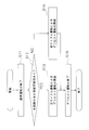
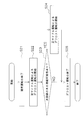
- FIG. 1 and FIG. 3 are circuit configuration diagrams of the heat pump hot water heater 10 when the refrigerant circuit 20 is in a forward cycle operation.
- FIG. 2 is a circuit configuration diagram of the heat pump hot water heater 10 during the reverse cycle operation of the refrigerant circuit 20. 1 to 3, the flow direction of the refrigerant circulating through the refrigerant circuit 20 is indicated by arrows.
- the forward cycle operation of the refrigerant circuit 20 is performed during normal operation or defrost operation of the heat pump hot water heater 10.
- the reverse cycle operation of the refrigerant circuit 20 is performed during the defrost operation of the heat pump hot water heater 10.
- the normal operation of the heat pump hot water heater 10 is an operation in which the water circulating in the water circuit 30 is heated and the generated hot water is used for heating.
- the defrosting operation of the heat pump hot water heater 10 is an operation for removing frost attached to the first heat exchanger 21.
- the refrigerant circuit 20 can switch between the normal cycle operation and the reverse cycle operation.
- the first heat exchanger 21 is a refrigerant-air heat exchanger. In the first heat exchanger 21, heat exchange is performed between the refrigerant circulating in the refrigerant circuit 20 and the heat source.
- the heat source is, for example, outside air and geothermal heat. In the present embodiment, the heat source is outside air.
- the first heat exchanger 21 is, for example, a plate fin coil heat exchanger.
- a fan 21 a is installed in the vicinity of the first heat exchanger 21. The fan 21 a blows outside air to the first heat exchanger 21 and discharges outside air heat-exchanged with the refrigerant in the first heat exchanger 21.
- the first heat exchanger 21 is an outdoor heat exchanger installed outdoors.
- the compressor 22 is a compressor that sucks and compresses low-pressure refrigerant flowing through the refrigerant circuit 20 and discharges high-temperature and high-pressure refrigerant.
- the compressor 22 is a rotary compressor, for example.
- the expansion valve 23 is an electric valve for adjusting the flow rate and pressure of the refrigerant circulating in the refrigerant circuit 20.
- the four-way switching valve 24 is a switching valve for switching the forward cycle operation and the reverse cycle operation to reverse the refrigerant circulation direction in the refrigerant circuit 20.
- the four-way switching valve 24 has a first port 24a, a second port 24b, a third port 24c, and a fourth port 24d.
- the four-way switching valve 24 is in the first communication state or the second communication state. In the first communication state, as shown in FIGS. 1 and 3, the first port 24a and the second port 24b communicate with each other, and the third port 24c and the fourth port 24d communicate with each other. In the second communication state, as shown in FIG. 2, the first port 24a and the third port 24c communicate with each other, and the second port 24b and the fourth port 24d communicate with each other.
- the refrigerant circuit 20 performs the normal cycle operation
- the four-way switching valve 24 is in the first communication state.
- the four-way switching valve 24 is in the second communication state.
- the second heat exchanger 25 is a water-refrigerant heat exchanger. In the second heat exchanger 25, heat exchange is performed between the refrigerant circulating in the refrigerant circuit 20 and the water circulating in the water circuit 30. The refrigerant circuit 20 and the water circuit 30 share the second heat exchanger 25.
- the second heat exchanger 25 includes a refrigerant heat exchanging portion 25 a through which the refrigerant circulating in the refrigerant circuit 20 passes and a water heat exchanging portion 25 b through which water circulating in the water circuit 30 passes.
- a refrigerant pipe that is the refrigerant heat exchange section 25a is spirally wound around the outer circumference of a water pipe that is the water heat exchange section 25b, and a groove is formed inside the water pipe. It is a tornado type heat exchanger which has the composition which has.
- the second heat exchanger 25 is an indoor heat exchanger installed in a space to be heated.
- the first temperature sensor 26 is a sensor that measures the temperature of the outside air heat-exchanged by the first heat exchanger 21.
- the first temperature sensor 26 measures the temperature of the outside air blown to the first heat exchanger 21 by the fan 21a or the temperature of the outdoor air where the first heat exchanger 21 is installed.
- the first temperature sensor 26 is attached to the first heat exchanger 21.
- the configuration of the refrigerant circuit 20 during the normal cycle operation will be described.
- the discharge side of the compressor 22 is connected to the first port 24 a of the four-way switching valve 24.
- the second port 24 b of the four-way switching valve 24 is connected to the refrigerant heat exchange unit 25 a of the second heat exchanger 25.
- the refrigerant heat exchange unit 25 a of the second heat exchanger 25 is connected to the expansion valve 23.
- the expansion valve 23 is connected to the first heat exchanger 21.
- the first heat exchanger 21 is connected to the third port 24 c of the four-way switching valve 24.
- the fourth port 24 d of the four-way switching valve 24 is connected to the suction side of the compressor 21.
- the normal cycle operation is performed during normal operation of the heat pump hot water heater 10.
- the refrigerant is sucked into the compressor 22 as a low-pressure gas refrigerant and compressed.
- the compressed refrigerant is discharged from the compressor 22 as a high-temperature and high-pressure gas refrigerant, passes through the first port 24a and the second port 24b of the four-way switching valve 24, and is sent to the second heat exchanger 25.
- the refrigerant passes through the refrigerant heat exchange unit 25a, and the water passes through the water heat exchange unit 25b.
- heat is transferred between the refrigerant and water by transferring heat from the high-temperature refrigerant to the low-temperature water.
- the refrigerant coolant which is a high temperature / high pressure gas refrigerant condenses and turns into a high pressure liquid refrigerant. Then, the refrigerant is decompressed by passing through the expansion valve 23, and becomes a low-pressure gas-liquid two-phase refrigerant. The low-pressure gas-liquid two-phase refrigerant evaporates by heat exchange with the outside air in the first heat exchanger 21 to become a low-pressure gas refrigerant. Then, the refrigerant passes through the third port 24 c and the fourth port 24 d of the four-way switching valve 24 and is sent to the compressor 22.
- the refrigerant circuit 20 that performs the normal cycle operation supplies the heat of the outside air to the water circulating through the water circuit 30 through the refrigerant by repeating the above steps.
- the refrigerant circuit 20 performs a normal cycle operation or a reverse cycle operation during the defrost operation of the heat pump hot water heater 10. The operation of the refrigerant circuit 20 during the reverse cycle operation will be described later.
- the water circuit 30 is a circuit in which the second heat exchanger 25, the water supply pump 31, the hot water storage tank 32, and the heating unit 33 are mainly connected.
- the water circuit 30 has a second temperature sensor 34.
- water circulates.
- water circulates in the order of the water supply pump 31, the second heat exchanger 25, the hot water storage tank 32, the heating unit 33, and the water supply pump 31. 1 and 2, the flow direction of the water circulating through the water circuit 30 is indicated by arrows.
- the feed water pump 31 is a pump for sending the water flowing through the water circuit 30 to the water heat exchanger 25b of the second heat exchanger 25.
- the second heat exchanger 25 is a water-refrigerant heat exchanger. As described above, in the second heat exchanger 25, heat exchange is performed between the refrigerant circulating in the refrigerant circuit 20 and the water circulating in the water circuit 30. The water that is heat-exchanged in the second heat exchanger 25 passes through the water heat exchanger 25b.
- the inlet of the water heat exchanger 25b is connected to the water supply pump 31 via a pipe.
- the outlet of the water heat exchanger 25b is connected to the hot water storage tank 32 via a pipe.
- the hot water storage tank 32 is a tank for storing the water heated by the second heat exchanger 25. Hot water stored in the hot water storage tank 32 is sent to the heating unit 33.
- the hot water storage tank 32 may be provided with a heat insulation heater for keeping the stored hot water warm.
- the heating unit 33 is installed in a space where heating is performed by normal operation of the heat pump hot water heater 10.
- the heating unit 33 is a floor heating panel installed on the floor of a room, for example.
- the heating unit 33 has a heating pipe 33a through which hot water heated by the second heat exchanger 25 flows.
- the second temperature sensor 34 is a sensor that measures the temperature of the water flowing into the water heat exchanger 25b of the second heat exchanger 25.
- the 2nd temperature sensor 34 is attached to piping near the entrance of water heat exchange part 25b, for example. The operation of the water circuit 30 will be described. Water is sent to the second heat exchanger 25 by the water supply pump 31.
- the second heat exchanger 25 heat is transferred between the refrigerant and water by transferring heat from the high-temperature refrigerant to the low-temperature water. Thereby, in the 2nd heat exchanger 25, water is heated. The water heated by the second heat exchanger 25 is sent to the hot water storage tank 32 as hot water. Hot water stored in the hot water storage tank 32 is supplied to the heating unit 33. In the heating unit 33, hot water flows through the heating pipe 33a, thereby heating the air in the space where the heating unit 33 is installed. The water whose temperature has decreased after passing through the heating pipe 33 a is sent to the water supply pump 31.
- the control unit 40 is a computer for controlling each component of the heat pump hot water heater 10.
- the control unit 40 is connected to the compressor 22, the expansion valve 23, the four-way switching valve 24, the first temperature sensor 26, the water supply pump 31, the heating unit 33, and the second temperature sensor 34.
- the control unit 40 is installed in, for example, an electrical component unit (not shown) inside the heat pump hot water heater 10.
- the control unit 40 can start and stop the compressor 22 by adjusting the operating frequency of the compressor 22.
- the controller 40 can control the flow rate of the refrigerant passing through the expansion valve 23 by adjusting the opening degree of the expansion valve 23.
- the control unit 40 can start and stop the feed water pump 31 by controlling the rotation speed of the feed water pump 31.
- the control unit 40 can adjust the temperature of the space in which the heating unit 33 is installed by adjusting the flow rate of hot water sent to the heating unit 33.
- the controller 40 can control the four-way switching valve 24 to switch between the first communication state and the second communication state. That is, the control unit 40 can switch between the normal cycle operation and the reverse cycle operation by controlling the four-way switching valve 24.
- the control unit 40 can receive the temperature of the air that is heat-exchanged by the first heat exchanger 21 that is measured by the first temperature sensor 26 of the refrigerant circuit 20.
- the controller 40 can receive the temperature of the water flowing into the water heat exchanger 25b of the second heat exchanger 25 measured by the second temperature sensor 34 of the water circuit 30.
- the control unit 40 stores information related to the operation of the heat pump hot water heater 10. For example, the control unit 40 monitors and stores the time when the compressor 22 is activated and the time when the compressor 22 is stopped.
- control part 40 is the time when the compressor 22 has stopped continuously, the time when the normal operation of the heat pump hot water heater 10 is performed continuously, and the defrost of the heat pump hot water heater 10, for example.
- the time during which the operation is continuously performed can be calculated.
- FIG. 1 is a circuit configuration diagram of a heat pump hot water heater 10 during normal operation.
- the refrigerant circuit 20 performs forward cycle operation.
- the four-way switching valve 24 of the refrigerant circuit 20 is in the first communication state.
- water is sent to the second heat exchanger 25 by the water supply pump 31, the water is heated in the second heat exchanger 25, and hot water is sent to the hot water storage tank 32 and the heating unit 33.
- the first heat exchanger 21 of the refrigerant circuit 20 performs heat exchange in which heat is transferred from the outside air to the refrigerant. That is, the outside air blown by the fan 21 a is deprived of heat in the first heat exchanger 21. Therefore, frost may adhere to the first heat exchanger 21 under conditions where the temperature of the outside air is low, such as in cold regions and in winter. When frost adheres to the first heat exchanger 21, the efficiency of heat exchange in the first heat exchanger 21 is lower than in the state where frost does not adhere to the first heat exchanger 21, and the heat pump hot water heater 10 operation efficiency will fall.
- the heat pump hot water heater 10 it is necessary for the heat pump hot water heater 10 to periodically perform a defrost operation for removing frost attached to the first heat exchanger 21 in order to suppress a decrease in operation efficiency under a condition where the temperature of the outside air is low. is there.
- the defrosting operation of the heat pump hot water heater 10 is performed by melting frost attached to the first heat exchanger 21 with heat.
- FIG. 2 is a circuit configuration diagram of the heat pump hot water heater 10 during the defrost operation by the reverse cycle operation.
- FIG. 3 is a circuit configuration diagram of the heat pump hot water heater 10 during the defrost operation by the normal cycle operation.
- the refrigerant circulation direction in the refrigerant circuit 20 in the reverse cycle operation is opposite to the refrigerant circulation direction in the normal cycle operation.
- the refrigerant in the refrigerant circuit 20 includes the compressor 22, the four-way switching valve 24 (first port 24a and third port 24c), the first heat exchanger 21, the expansion valve 23, and the second.
- the heat exchanger 25, the four-way switching valve 24 (second port 24b and fourth port 24d), and the compressor 22 are circulated in order.
- the control unit 30 sets the rotation speed of the compressor 22 to zero and stops the compressor 22.
- the normal operation ends when the compressor 22 is stopped.
- the control unit 30 switches the four-way switching valve 24 from the first communication state to the second communication state.
- the control unit 30 increases the rotational speed of the compressor 22 from zero and starts the operation of the compressor 22.
- the defrosting operation of the heat pump device 10 is started by starting the compressor 22. During the defrost operation, the high-temperature refrigerant discharged from the compressor 22 flows into the first heat exchanger 21.
- the heat accumulated in the second heat exchanger 25 during the normal operation is supplied to the first heat exchanger 21 via the refrigerant circulating in the refrigerant circuit 20.
- the frost adhering to the 1st heat exchanger 21 melts, and the 1st heat exchanger 21 is defrosted.
- the water supply pump 31 of the water circuit 30 is operating.
- the control part 30 makes the rotation speed of the water supply pump 31 zero, and stops the water supply pump 31.
- FIG. By stopping the feed pump 31, the supply of water to the second heat exchanger 25 is stopped.
- the control unit 30 increases the opening degree of the expansion valve 23. Further, the control unit 30 maintains the four-way switching valve 24 in the first communication state. That is, during the defrost operation by the normal cycle operation, the high-temperature refrigerant discharged from the compressor 22 is supplied to the second heat exchanger 25 as in the normal operation.
- the second heat exchanger 25 since water does not pass through the water heat exchanger 25b, heat exchange between the refrigerant and water in the second heat exchanger 25 is suppressed. Therefore, the heat of the high-temperature refrigerant supplied from the compressor 22 is accumulated in the second heat exchanger 25. As a result, the temperature of the second heat exchanger 25 increases. Further, the temperature of the compressor 22 also increases due to the operation of the compressor 22. The heat accumulated in the compressor 22 and the second heat exchanger 25 is supplied to the first heat exchanger 21 via the expansion valve 23 via the refrigerant circulating in the refrigerant circuit 20. Thereby, the frost adhering to the 1st heat exchanger 21 melts, and the 1st heat exchanger 21 is defrosted.
- the control unit 40 determines whether water water in the water circuit 30 can be frozen, and performs defrost operation by normal cycle operation. Alternatively, it is selected whether to perform defrost operation by reverse cycle operation. When it is determined that the water in the water circuit 30 may freeze, the control unit 40 performs the defrost operation by the normal cycle operation. When it is determined that the water in the water circuit 30 is not likely to freeze, the control unit 40 performs the defrost operation by the reverse cycle operation. The time when the control unit 40 determines the possibility of water freezing in the water circuit 30 is at least one of when the normal operation ends and the defrost operation starts, or when the defrost operation is performed by the reverse cycle operation.
- FIG. 4 is a flowchart illustrating a routine in which the control unit 40 determines the possibility of water freezing in the water circuit 30 when the normal operation ends and the defrost operation starts.
- This routine is composed of steps S11 to S15.
- step S11 the control unit 40 stops the normal operation.
- step S ⁇ b> 12 the control unit 40 determines the possibility of water freezing in the water circuit 30. If the control unit 40 determines that the water in the water circuit 30 may be frozen, it executes Step S13, and if it determines that there is no possibility of freezing, it executes Step S14.
- step S13 the control unit 40 starts the defrost operation by the normal cycle operation.
- step S14 the control unit 40 starts defrost operation by reverse cycle operation.
- step S15 the control unit 40 stops the defrost operation.
- FIG. 5 is a flowchart illustrating a routine in which the control unit 40 determines the possibility of water freezing in the water circuit 30 during execution of the defrost operation by the reverse cycle operation.
- This routine is composed of steps S21 to S25.
- step S21 the control unit 40 stops the normal operation.
- step S22 the control unit 40 starts defrosting operation by reverse cycle operation.
- step S ⁇ b> 23 the control unit 40 determines the possibility of water freezing in the water circuit 30.
- the control unit 40 determines that the water in the water circuit 30 is likely to freeze, it executes step S24, and when it is determined that there is no possibility of freezing, the defrosting operation by the reverse cycle operation is continued.
- step S24 the control unit 40 stops the defrost operation by the reverse cycle operation and starts the defrost operation by the normal cycle operation.
- step S25 the control unit 40 stops the defrost operation.
- control unit 40 determines the possibility of water freezing in the water circuit 30 based on any one of six determination criteria described below. Next, each criterion will be described.
- the control unit 40 determines the possibility of water freezing in the water circuit 30 when the normal operation is terminated and the defrost operation is started.
- the control unit 40 acquires the temperature of the water flowing into the water heat exchange unit 25b of the second heat exchanger 25 from the second temperature sensor 34 of the water circuit 30.
- the control unit 40 stops the water supply pump 31, maintains the four-way switching valve 24 in the first communication state, and performs the normal cycle operation.
- Start defrost operation When the temperature of the water flowing into the water heat exchanger 25b exceeds a predetermined temperature, the control unit 40 switches the four-way switching valve 24 from the first communication state to the second communication state, and starts defrost operation by reverse cycle operation. To do.
- the control unit 40 determines the possibility of water freezing in the water circuit 30 when the normal operation is terminated and the defrost operation is started.
- the control unit 40 acquires the temperature of air that is heat-exchanged by the first heat exchanger 21 from the first temperature sensor 26 of the refrigerant circuit 20.
- the control unit 40 stops the feed water pump 31 and maintains the four-way switching valve 24 in the first communication state.
- the control unit 40 switches the four-way switching valve 24 from the first communication state to the second communication state when the air heat-exchanged in the first heat exchanger 21 exceeds a predetermined temperature, and performs the defrost operation by the reverse cycle operation. Start.
- the control unit 40 determines the possibility of water freezing in the water circuit 30 when the normal operation is terminated and the defrost operation is started.
- the control unit 40 acquires information related to the operation of the compressor 22 of the refrigerant circuit 20.
- the control unit 40 stops the water supply pump 31 and maintains the four-way switching valve 24 in the first communication state when the time during which the compressor 22 is continuously stopped before the start of the defrost operation is a predetermined time or longer. Then, the defrost operation by the normal cycle operation is started.
- the control unit 40 switches the four-way switching valve 24 from the first communication state to the second communication state, Start defrost operation by reverse cycle operation.
- the control unit 40 determines the possibility of water freezing in the water circuit 30 when the normal operation is terminated and the defrost operation is started.
- the control unit 40 acquires information related to the defrost operation of the heat pump hot water heater 10.
- the control unit 40 stops the water supply pump 31, maintains the four-way switching valve 24 in the first communication state, and starts the defrost operation by the normal cycle operation. To do.
- the control unit 40 switches the four-way switching valve 24 from the first communication state to the second communication state, and starts the defrost operation by the reverse cycle operation.
- the control unit 40 freezes the water in the water circuit 30 when the normal operation is terminated and the defrost operation is performed by the reverse cycle operation. Determine the possibility.
- the control unit 40 acquires the temperature of the water flowing into the water heat exchange unit 25b of the second heat exchanger 25 from the second temperature sensor 34 of the water circuit 30.
- the control unit 40 stops the water supply pump 31 of the water circuit 30 and changes the four-way switching valve 24 from the second communication state to the first communication state.
- the control unit 40 continues the defrost operation by the reverse cycle operation.
- the control unit 40 freezes the water in the water circuit 30 when the normal operation is terminated and the defrost operation is performed by the reverse cycle operation. Determine the possibility.
- the control unit 40 acquires the temperature of the water flowing into the water heat exchange unit 25b of the second heat exchanger 25 from the second temperature sensor 34 of the water circuit 30.
- the control unit 40 switches the four-way switching valve 24 from the second communication state to the first communication state, stops the defrost operation, Start normal operation by normal cycle operation.
- the control unit 40 continues the defrost operation by the reverse cycle operation.
- This heat pump hot water heater 10 is a heat pump device including a refrigerant circuit 20 and a water circuit 30 that share the second heat exchanger 25.
- the high-temperature refrigerant compressed by the compressor 22 of the refrigerant circuit 20 is heat-exchanged with water flowing through the water circuit 30 in the second heat exchanger 25.
- heat is transferred from the refrigerant flowing through the refrigerant heat exchange unit 25a to the water flowing through the water heat exchange unit 25b.
- the water which flows through the water circuit 30 is heated, and hot water is produced
- the generated hot water is temporarily stored in the hot water storage tank 32 and used for heating the room by the heating unit 33.
- the control unit 40 can control the four-way switching valve 24 of the refrigerant circuit 20 to switch between the normal cycle operation and the reverse cycle operation.
- frost may adhere in the conditions where the temperature of outside air is low.
- the heat pump hot water heater 10 can perform a defrost operation for removing frost attached to the first heat exchanger 21.
- the control unit 40 normally performs defrost operation by reverse cycle operation. However, when it is determined that the water flowing through the water circuit 30 may be frozen by performing the defrost operation by the reverse cycle operation, the control unit 40 performs the defrost operation by the normal cycle operation.
- the defrost operation by the normal cycle operation is performed by stopping the operation of the water supply pump 31 of the water circuit 30 and increasing the opening degree of the expansion valve 23 of the refrigerant circuit 20.
- By stopping the feed water pump 31 heat exchange in the second heat exchanger 25 is suppressed, and heat is accumulated in the second heat exchanger 25.
- the heat pump hot water heater 10 selects and executes either the defrost operation by the normal cycle operation or the defrost operation by the reverse cycle operation based on the possibility of freezing of the water flowing through the water circuit 30.
- the defrost operation by the reverse cycle operation the high-temperature refrigerant compressed by the compressor 22 directly flows into the first heat exchanger 21, so that frost attached to the first heat exchanger 21 is efficiently removed.
- the second heat exchanger 25 performs heat exchange in which heat is transferred from the water flowing through the water circuit 30 to the refrigerant flowing through the refrigerant circuit 20.
- the heat pump hot water heater 10 can prevent freezing of water during the defrost operation.
- the control unit 40 of the heat pump hot water heater 10 determines the possibility of water freezing in the water circuit 30 based on the first to sixth determination criteria, and performs the defrost operation by the normal cycle operation or vice versa. Select whether to perform defrost operation by cycle operation. Based on the first criterion, the control unit 40 performs the defrost operation by the reverse cycle operation when the temperature of the water flowing into the second heat exchanger 25 is equal to or lower than a predetermined temperature at the start of the defrost operation. It is determined that there is a possibility that the water in the water circuit 30 is frozen by performing. In this case, the heat pump hot water heater 10 can prevent freezing of water in the water circuit 30 by terminating the normal operation and starting the defrost operation by the normal cycle operation.
- control unit 40 performs the reverse cycle operation when the temperature of the air exchanged in the first heat exchanger 21 is equal to or lower than a predetermined temperature at the start of the defrost operation based on the second determination criterion. It is determined that the water in the water circuit 30 may be frozen by performing the defrost operation. In this case, the heat pump hot water heater 10 can prevent freezing of water in the water circuit 30 by terminating the normal operation and starting the defrost operation by the normal cycle operation.
- control unit 40 based on the third determination criterion, at the start of the defrost operation, when the stop time of the normal operation for heating the water of the water circuit 30 by the normal cycle operation is a predetermined time or more, It is determined that the water in the water circuit 30 may be frozen by performing the defrost operation by the reverse cycle operation.
- the heat pump hot water heater 10 can prevent freezing of water in the water circuit 30 by terminating the normal operation and starting the defrost operation by the normal cycle operation.
- the control unit 40 performs the defrost operation by the reverse cycle operation when the execution time of the previous defrost operation is equal to or less than a predetermined time at the start of the defrost operation. It is determined that the water in the water circuit 30 may be frozen. In this case, the heat pump hot water heater 10 can prevent freezing of water in the water circuit 30 by terminating the normal operation and starting the defrost operation by the normal cycle operation.
- control unit 40 performs reverse operation when the temperature of the water flowing into the second heat exchanger 25 is equal to or lower than a predetermined temperature when the defrost operation is performed by the reverse cycle operation based on the fifth determination criterion. It is determined that the water flowing through the water circuit 30 may be frozen by continuing the defrost operation by the cycle operation. In this case, the heat pump hot water heater 10 stops the defrost operation by the reverse cycle operation and starts the defrost operation by the normal cycle operation. Further, the control unit 40 performs reverse operation when the temperature of the water flowing into the second heat exchanger 25 is equal to or lower than a predetermined temperature when performing the defrost operation by the reverse cycle operation based on the sixth determination criterion. It is determined that the water flowing through the water circuit 30 may be frozen by continuing the defrost operation by the cycle operation. In this case, the heat pump hot water heater 10 stops the defrost operation by the reverse cycle operation and starts the normal operation by the normal cycle operation.
- the temperature of the water flowing into the second heat exchanger 25 does not decrease, so that the water in the water circuit 30 is less likely to freeze.
- the time required for defrosting the first heat exchanger 21 is increased because the temperature of the first heat exchanger 21 is unlikely to rise until sufficient heat is accumulated in the second heat exchanger 25. Therefore, when the heat pump hot water heater 10 performs only the defrost operation by the normal cycle operation, the average heating capacity decreases. Moreover, when the heat pump hot water heater 10 performs only the defrost operation by reverse cycle operation, the water of the water circuit 30 may freeze.
- the heat pump hot water heater 10 selects whether to perform the defrost operation by the reverse cycle operation or the defrost operation by the normal cycle operation according to the possibility that the water in the water circuit 30 is frozen. Thereby, the heat pump hot water heater 10 can prevent the water in the water circuit 30 from freezing and can secure an average heating capacity.
- the control unit 40 of the heat pump hot water heater 10 determines the possibility of water freezing in the water circuit 30 based on any one of the first to sixth determination criteria. However, the control unit 40 selects a plurality of determination criteria from the first to sixth determination criteria, and determines the water freezing possibility of the water circuit 30 based on the determination criteria obtained by combining the selected plurality of determination criteria. You may judge. For example, when the heat pump hot water heater 10 ends the normal operation and starts the defrost operation, the heat pump hot water heater 10 may start the defrost operation based on the first determination criterion and the second determination criterion.
- control unit 40 is configured such that the temperature of the water flowing into the water heat exchange unit 25b is equal to or lower than a predetermined temperature, or the temperature of air exchanged in the first heat exchanger 21 is equal to or lower than the predetermined temperature.
- the defrost operation by the normal cycle operation may be started. Further, in this case, the control unit 40 determines that the temperature of the water flowing into the water heat exchange unit 25b is equal to or lower than a predetermined temperature and the temperature of the air exchanged in the first heat exchanger 21 is a predetermined temperature.
- the defrost operation by the normal cycle operation may be started.
- the heat pump hot water heater 10 starts the defrost operation based on the first determination criterion and executes the defrost operation by the reverse cycle operation.
- the defrost operation by the reverse cycle operation may be stopped and the defrost operation by the normal cycle operation may be started based on the fifth determination criterion.
- the heat pump hot water heater 10 may stop the defrost operation by the normal cycle operation and start the defrost operation by the reverse cycle operation when performing the defrost operation by the normal cycle operation.
- the control unit 40 may start the defrost operation based on the reverse cycle operation based on the fifth determination criterion. That is, at the time of performing the defrost operation by the normal cycle operation, the control unit 40 activates the water supply pump 31 of the water circuit 30 when the temperature of the water flowing into the water heat exchange unit 25b exceeds a predetermined temperature, The defrost operation by the reverse cycle operation may be started by switching the four-way switching valve 24 from the first communication state to the second communication state. In this case, when the temperature of the water flowing into the water heat exchanger 25b is equal to or lower than the predetermined temperature, the controller 40 continues the defrost operation by the normal cycle operation.
- control unit 40 determines that the possibility of water freezing in the water circuit 30 has become zero when the execution time of the defrost operation by the normal cycle operation exceeds a predetermined time.
- the defrost operation by reverse cycle operation may be started by starting the water supply pump 31 of the circuit 30 and switching the four-way switching valve 24 from the first communication state to the second communication state.
- the heat pump hot water heater according to the present invention can prevent water from freezing.
Landscapes
- Engineering & Computer Science (AREA)
- Physics & Mathematics (AREA)
- Thermal Sciences (AREA)
- Mechanical Engineering (AREA)
- General Engineering & Computer Science (AREA)
- Chemical & Material Sciences (AREA)
- Combustion & Propulsion (AREA)
- Heat-Pump Type And Storage Water Heaters (AREA)
- Compression-Type Refrigeration Machines With Reversible Cycles (AREA)
- Steam Or Hot-Water Central Heating Systems (AREA)
Abstract
ヒートポンプ温水暖房機(10)は、冷媒回路(20)と、水回路(30)と、制御部(40)とを備える。冷媒回路は、空気と冷媒とを熱交換させる第1熱交換器(21)と、冷媒と水とを熱交換させる第2熱交換器(25)と、冷媒を圧縮する圧縮機(22)とを有する。水回路は、第2熱交換器と、第2熱交換器に水を供給する給水機構(31)とを有する。制御部は、第1熱交換器のデフロスト運転を行うために、冷媒回路および水回路を制御する。冷媒回路は、正サイクル運転と、逆サイクル運転とを切り替え可能である。制御部は、デフロスト運転の開始時、および、デフロスト運転の実行時の少なくとも一方において、水回路の水の凍結可能性を判断して、正サイクル運転を行うか、または、逆サイクル運転を行うかを選択し、デフロスト運転を行う。
Description
本発明は、ヒートポンプ温水暖房機に関する。
従来、ヒートポンプシステムを利用する給湯器および温水暖房機等が用いられている。例えば、特許文献1(特開2010-181104号公報)には、冷媒回路および水回路を備えるヒートポンプ装置である給湯器が開示されている。冷媒回路は、圧縮機、室外熱交換器および室内熱交換器から構成され、冷媒が循環する回路である。水回路は、冷媒回路と室内熱交換器を共有し、水が流れる回路である。冷媒回路において、圧縮機で圧縮された高温の冷媒は、室内熱交換器において水と熱交換されて冷却され、減圧された後、室外熱交換器で外気と熱交換されて加熱される。水回路を流れる水は、室内熱交換器において冷媒と熱交換されて加熱される。
この給湯器のように、外気と冷媒との熱交換が行われる室外熱交換器を備えるヒートポンプ装置では、外気の温度が低い場合に、室外熱交換器に霜が付着して運転効率が低下することがある。この場合、ヒートポンプ装置は、室外熱交換器に付着した霜を融かすためのデフロスト運転を行う。例えば、ヒートポンプ装置は、冷媒回路における冷媒の循環方向を通常運転時と逆にする逆サイクル運転を行う。これにより、圧縮機で圧縮された高温の冷媒が室外熱交換器に流入して、室外熱交換器の除霜(デフロスト)が行われる。
この給湯器のように、外気と冷媒との熱交換が行われる室外熱交換器を備えるヒートポンプ装置では、外気の温度が低い場合に、室外熱交換器に霜が付着して運転効率が低下することがある。この場合、ヒートポンプ装置は、室外熱交換器に付着した霜を融かすためのデフロスト運転を行う。例えば、ヒートポンプ装置は、冷媒回路における冷媒の循環方向を通常運転時と逆にする逆サイクル運転を行う。これにより、圧縮機で圧縮された高温の冷媒が室外熱交換器に流入して、室外熱交換器の除霜(デフロスト)が行われる。
しかし、外気の温度が低い条件下において、逆サイクル運転によるデフロストを長時間行うと、水回路の水が凍結するおそれがある。水の凍結を防止するために、水回路に残っている湯の熱を利用して室外熱交換器をデフロストするヒートポンプ装置が知られている。例えば、特許文献1には、水回路に接続される貯湯タンク内の湯を室内熱交換器に流して、室内熱交換器に熱を蓄積した後に、逆サイクル運転によるデフロストを行うヒートポンプ装置が開示されている。また、特許文献2(国際公開第2006/103815号)には、水回路に残っている湯の熱を利用して逆サイクル運転によるデフロストを行うモードと、冷媒回路の圧縮機から吐出された高温の冷媒を室外熱交換器に通し、室外熱交換器を通過した冷媒をそのまま圧縮機に戻してデフロストを行うモードとを有するヒートポンプ装置が開示されている。
しかし、これらのヒートポンプ装置では、室外熱交換器のデフロストを行うために、冷媒回路または水回路の構成を変更する必要がある。また、冷媒回路の逆サイクル運転によって室外熱交換器をデフロストする場合、水回路の水の温度、および、外気の温度が低い条件下において、依然として、水回路の水が凍結するおそれがある。
本発明の目的は、水の凍結を防止することができるヒートポンプ温水暖房機を提供することである。
本発明の目的は、水の凍結を防止することができるヒートポンプ温水暖房機を提供することである。
本発明の第1観点に係るヒートポンプ温水暖房機は、冷媒回路と、水回路と、制御部とを備える。冷媒回路は、冷媒が循環する回路である。冷媒回路は、空気と冷媒とを熱交換させる第1熱交換器と、冷媒と水とを熱交換させる第2熱交換器と、冷媒を圧縮する圧縮機とを有する。水回路は、水が流れる回路である。水回路は、第2熱交換器と、第2熱交換器に水を供給する給水機構とを有する。制御部は、第1熱交換器のデフロスト運転を行うために、冷媒回路および水回路を制御する。冷媒回路は、正サイクル運転と、逆サイクル運転とを切り替え可能である。正サイクル運転では、圧縮機、第2熱交換器、第1熱交換器および圧縮機の順に、冷媒が循環する。逆サイクル運転では、圧縮機、第1熱交換器、第2熱交換器および圧縮機の順に、冷媒が循環する。制御部は、デフロスト運転の開始時、および、デフロスト運転の実行時の少なくとも一方において、水回路の水の凍結可能性を判断して、正サイクル運転を行うか、または、逆サイクル運転を行うかを選択し、デフロスト運転を行う。
このヒートポンプ温水暖房機は、第2熱交換器を共有する冷媒回路および水回路を備えるヒートポンプ装置である。冷媒回路の圧縮機で圧縮された高温の冷媒は、第2熱交換器において、水回路を流れる水と熱交換される。第2熱交換器では、冷媒回路を流れる冷媒から、水回路を流れる水に、熱が移動する。これにより、水回路を流れる水が加熱されて、湯が生成される。制御部は、冷媒回路を制御して、正サイクル運転と逆サイクル運転とを切り替えることができる。正サイクル運転では、圧縮機で圧縮された高温の冷媒は第2熱交換器に流入し、逆サイクル運転では、圧縮機で圧縮された高温の冷媒は第1熱交換器に流入する。屋外に設置される第1熱交換器は、外気の温度が低い条件下において、霜が付着する場合がある。このヒートポンプ温水暖房機は、第1熱交換器に付着した霜を除去するデフロスト運転を行う。制御部は、通常、逆サイクル運転によるデフロスト運転を行う。しかし、制御部は、逆サイクル運転によるデフロスト運転を行うことで水回路を流れる水が凍結する可能性があると判断した場合には、正サイクル運転によるデフロスト運転を行う。正サイクル運転によるデフロスト運転は、水回路の給水機構の運転を停止して、冷媒回路の膨張機構の開度を上げることで行われる。給水機構の停止により、第2熱交換器における熱交換が抑制され、第2熱交換器に熱が蓄積される。膨張機構の開度を上げることで、圧縮機および第2熱交換器の熱が、冷媒を介して、膨張機構を経由して第1熱交換器に伝達される。これにより、第1熱交換器が加熱されて、第1熱交換器に付着した霜が除去される。
このヒートポンプ温水暖房機は、水回路を流れる水の凍結可能性に基づいて、正サイクル運転によるデフロスト運転、または、逆サイクル運転によるデフロスト運転のいずれかを選択して実行する。逆サイクル運転によるデフロスト運転では、圧縮機で圧縮された高温の冷媒が第1熱交換器に直接流入するので、第1熱交換器に付着した霜が効率的に除去される。しかし、第2熱交換器において、水回路を流れる水から冷媒回路を流れる冷媒に熱が移動する熱交換が行われるため、水回路の水の温度が低い場合等において、水回路の水が凍結して水回路が破壊されるおそれがある。一方、正サイクル運転によるデフロスト運転では、第2熱交換器における熱交換が抑制された状態で、圧縮機および第2熱交換器の熱によって、第1熱交換器に付着した霜が除去される。そのため、正サイクル運転によるデフロスト運転では、水回路の水が凍結するおそれがない。従って、このヒートポンプ温水暖房機は、デフロスト運転時における水の凍結を防止することができる。
本発明の第2観点に係るヒートポンプ温水暖房機は、第1観点に係るヒートポンプ温水暖房機であって、制御部は、デフロスト運転の開始時において、第2熱交換器に流入する水の温度が第1温度以下である場合に、正サイクル運転を行うことを選択し、かつ、給水機構の運転を停止する。
このヒートポンプ温水暖房機は、デフロスト運転の開始時に、正サイクル運転によるデフロスト運転、または、逆サイクル運転によるデフロスト運転のいずれかを選択して実行する。制御部は、第2熱交換器に流入する水の温度が所定の温度以下である場合に、逆サイクル運転によるデフロスト運転を行うことで水回路を流れる水が凍結する可能性があると判断する。この場合、このヒートポンプ温水暖房機は、正サイクル運転によるデフロスト運転を開始する。
このヒートポンプ温水暖房機は、デフロスト運転の開始時に、正サイクル運転によるデフロスト運転、または、逆サイクル運転によるデフロスト運転のいずれかを選択して実行する。制御部は、第2熱交換器に流入する水の温度が所定の温度以下である場合に、逆サイクル運転によるデフロスト運転を行うことで水回路を流れる水が凍結する可能性があると判断する。この場合、このヒートポンプ温水暖房機は、正サイクル運転によるデフロスト運転を開始する。
本発明の第3観点に係るヒートポンプ温水暖房機は、第1観点または第2観点に係るヒートポンプ温水暖房機であって、制御部は、デフロスト運転の開始時において、第1熱交換器で熱交換される空気の温度が第2温度以下である場合に、正サイクル運転を行うことを選択し、かつ、給水機構の運転を停止する。
このヒートポンプ温水暖房機は、デフロスト運転の開始時に、正サイクル運転によるデフロスト運転、または、逆サイクル運転によるデフロスト運転のいずれかを選択して実行する。制御部は、第1熱交換器で熱交換される空気の温度が所定の温度以下である場合に、逆サイクル運転によるデフロスト運転を行うことで水回路を流れる水が凍結する可能性があると判断する。この場合、このヒートポンプ温水暖房機は、正サイクル運転によるデフロスト運転を開始する。
このヒートポンプ温水暖房機は、デフロスト運転の開始時に、正サイクル運転によるデフロスト運転、または、逆サイクル運転によるデフロスト運転のいずれかを選択して実行する。制御部は、第1熱交換器で熱交換される空気の温度が所定の温度以下である場合に、逆サイクル運転によるデフロスト運転を行うことで水回路を流れる水が凍結する可能性があると判断する。この場合、このヒートポンプ温水暖房機は、正サイクル運転によるデフロスト運転を開始する。
本発明の第4観点に係るヒートポンプ温水暖房機は、第1観点から第3観点のいずれかに係るヒートポンプ温水暖房機であって、制御部は、デフロスト運転の開始時において、デフロスト運転の開始前に圧縮機が停止している時間が第1時間以上である場合に、正サイクル運転を行うことを選択し、かつ、給水機構の運転を停止する。
このヒートポンプ温水暖房機は、デフロスト運転の開始時に、正サイクル運転によるデフロスト運転、または、逆サイクル運転によるデフロスト運転のいずれかを選択して実行する。制御部は、デフロスト運転の開始時において、正サイクル運転によって水回路の水を加熱する通常運転の停止時間が所定の時間以上である場合に、逆サイクル運転によるデフロスト運転を行うことで水回路を流れる水が凍結する可能性があると判断する。この場合、このヒートポンプ温水暖房機は、正サイクル運転によるデフロスト運転を開始する。
このヒートポンプ温水暖房機は、デフロスト運転の開始時に、正サイクル運転によるデフロスト運転、または、逆サイクル運転によるデフロスト運転のいずれかを選択して実行する。制御部は、デフロスト運転の開始時において、正サイクル運転によって水回路の水を加熱する通常運転の停止時間が所定の時間以上である場合に、逆サイクル運転によるデフロスト運転を行うことで水回路を流れる水が凍結する可能性があると判断する。この場合、このヒートポンプ温水暖房機は、正サイクル運転によるデフロスト運転を開始する。
本発明の第5観点に係るヒートポンプ温水暖房機は、第1観点から第4観点のいずれかに係るヒートポンプ温水暖房機であって、制御部は、デフロスト運転の開始時において、前回のデフロスト運転の実行時間が第2時間以下である場合に、正サイクル運転を行うことを選択し、かつ、給水機構の運転を停止する。
このヒートポンプ温水暖房機は、デフロスト運転の開始時に、正サイクル運転によるデフロスト運転、または、逆サイクル運転によるデフロスト運転のいずれかを選択して実行する。制御部は、前回のデフロスト運転の実行時間が所定の時間以下である場合に、逆サイクル運転によるデフロスト運転を行うことで水回路を流れる水が凍結する可能性があると判断する。この場合、このヒートポンプ温水暖房機は、正サイクル運転によるデフロスト運転を開始する。
このヒートポンプ温水暖房機は、デフロスト運転の開始時に、正サイクル運転によるデフロスト運転、または、逆サイクル運転によるデフロスト運転のいずれかを選択して実行する。制御部は、前回のデフロスト運転の実行時間が所定の時間以下である場合に、逆サイクル運転によるデフロスト運転を行うことで水回路を流れる水が凍結する可能性があると判断する。この場合、このヒートポンプ温水暖房機は、正サイクル運転によるデフロスト運転を開始する。
本発明の第6観点に係るヒートポンプ温水暖房機は、第1観点から第5観点のいずれかに係るヒートポンプ温水暖房機であって、制御部は、逆サイクル運転によるデフロスト運転の実行時において、第2熱交換器に流入する水の温度が第3温度以下である場合に、正サイクル運転を行うことを選択し、かつ、給水機構の運転を停止する。
このヒートポンプ温水暖房機は、逆サイクル運転によるデフロスト運転の実行時に、正サイクル運転によるデフロスト運転、または、逆サイクル運転によるデフロスト運転のいずれかを選択して実行する。制御部は、逆サイクル運転によるデフロスト運転の実行時において、第2熱交換器に流入する水の温度が所定の温度以下である場合に、逆サイクル運転によるデフロスト運転を続けることで水回路を流れる水が凍結する可能性があると判断する。この場合、このヒートポンプ温水暖房機は、逆サイクル運転によるデフロスト運転を停止して、正サイクル運転によるデフロスト運転を開始する。
このヒートポンプ温水暖房機は、逆サイクル運転によるデフロスト運転の実行時に、正サイクル運転によるデフロスト運転、または、逆サイクル運転によるデフロスト運転のいずれかを選択して実行する。制御部は、逆サイクル運転によるデフロスト運転の実行時において、第2熱交換器に流入する水の温度が所定の温度以下である場合に、逆サイクル運転によるデフロスト運転を続けることで水回路を流れる水が凍結する可能性があると判断する。この場合、このヒートポンプ温水暖房機は、逆サイクル運転によるデフロスト運転を停止して、正サイクル運転によるデフロスト運転を開始する。
本発明の第7観点に係るヒートポンプ温水暖房機は、第1観点から第6観点のいずれかに係るヒートポンプ温水暖房機であって、制御部は、逆サイクル運転によるデフロスト運転の実行時において、第2熱交換器に流入する水の温度が第4温度以下である場合に、正サイクル運転を行うことを選択する。
このヒートポンプ温水暖房機は、逆サイクル運転によるデフロスト運転の実行時に、正サイクル運転によって水回路の水を加熱する通常運転、または、逆サイクル運転によるデフロスト運転のいずれかを選択して実行する。制御部は、逆サイクル運転によるデフロスト運転の実行時において、第2熱交換器に流入する水の温度が所定の温度以下である場合に、逆サイクル運転によるデフロスト運転を続けることで水回路を流れる水が凍結する可能性があると判断する。この場合、このヒートポンプ温水暖房機は、逆サイクル運転によるデフロスト運転を停止して、正サイクル運転による通常運転を開始する。
このヒートポンプ温水暖房機は、逆サイクル運転によるデフロスト運転の実行時に、正サイクル運転によって水回路の水を加熱する通常運転、または、逆サイクル運転によるデフロスト運転のいずれかを選択して実行する。制御部は、逆サイクル運転によるデフロスト運転の実行時において、第2熱交換器に流入する水の温度が所定の温度以下である場合に、逆サイクル運転によるデフロスト運転を続けることで水回路を流れる水が凍結する可能性があると判断する。この場合、このヒートポンプ温水暖房機は、逆サイクル運転によるデフロスト運転を停止して、正サイクル運転による通常運転を開始する。
本発明の第1観点乃至第7観点に係るヒートポンプ温水暖房機は、水の凍結を防止することができる。
本発明の実施形態に係るヒートポンプ温水暖房機について、図面を参照しながら説明する。本実施形態に係るヒートポンプ温水暖房機は、ヒートポンプシステムを利用して水を加熱し、生成された温水の熱を利用して室内の空気を加熱する暖房機である。
(1)ヒートポンプ温水暖房機の構成
本実施形態に係るヒートポンプ温水暖房機10は、主として、冷媒回路20と、水回路30と、制御部40とから構成される。冷媒回路20は、冷媒が循環する回路である。水回路30は、水が循環する回路である。冷媒回路20は、ヒートポンプとして機能する。
本実施形態に係るヒートポンプ温水暖房機10は、主として、冷媒回路20と、水回路30と、制御部40とから構成される。冷媒回路20は、冷媒が循環する回路である。水回路30は、水が循環する回路である。冷媒回路20は、ヒートポンプとして機能する。
(1-1)冷媒回路
冷媒回路20は、主として、第1熱交換器21と、圧縮機22と、膨張弁23と、四方切替弁24と、第2熱交換器25とが接続された冷媒回路である。冷媒回路20は、第1温度センサ26を有している。冷媒回路20を循環する冷媒は、例えば、R134aである。
冷媒回路20は、主として、第1熱交換器21と、圧縮機22と、膨張弁23と、四方切替弁24と、第2熱交換器25とが接続された冷媒回路である。冷媒回路20は、第1温度センサ26を有している。冷媒回路20を循環する冷媒は、例えば、R134aである。
冷媒回路20は、冷媒の循環方向に応じて、正サイクル運転または逆サイクル運転を行う。図1および図3は、冷媒回路20の正サイクル運転時におけるヒートポンプ温水暖房機10の回路構成図である。図2は、冷媒回路20の逆サイクル運転時におけるヒートポンプ温水暖房機10の回路構成図である。図1~3において、冷媒回路20を循環する冷媒の流れ方向は、矢印で示されている。冷媒回路20の正サイクル運転は、ヒートポンプ温水暖房機10の通常運転時またはデフロスト運転時に行われる。冷媒回路20の逆サイクル運転は、ヒートポンプ温水暖房機10のデフロスト運転時に行われる。ヒートポンプ温水暖房機10の通常運転は、水回路30を循環する水を加熱して、生成された湯を暖房に利用する運転である。ヒートポンプ温水暖房機10のデフロスト運転は、第1熱交換器21に付着した霜を除去する運転である。冷媒回路20は、正サイクル運転と逆サイクル運転とを切り替え可能である。
第1熱交換器21は、冷媒-空気熱交換器である。第1熱交換器21では、冷媒回路20を循環する冷媒と、熱源との間の熱交換が行われる。熱源は、例えば、外気および地熱である。本実施形態では、熱源は、外気である。第1熱交換器21は、例えば、プレートフィンコイル熱交換器である。第1熱交換器21の近傍には、ファン21aが設置されている。ファン21aは、第1熱交換器21に外気を送風し、第1熱交換器21において冷媒と熱交換された外気を排出する。第1熱交換器21は、屋外に設置される室外熱交換器である。
圧縮機22は、冷媒回路20を流れる低圧の冷媒を吸入して圧縮し、高温高圧の冷媒を吐出する圧縮機である。圧縮機22は、例えば、ロータリー圧縮機である。
膨張弁23は、冷媒回路20を循環する冷媒の流量および圧力を調節するための電動弁である。
圧縮機22は、冷媒回路20を流れる低圧の冷媒を吸入して圧縮し、高温高圧の冷媒を吐出する圧縮機である。圧縮機22は、例えば、ロータリー圧縮機である。
膨張弁23は、冷媒回路20を循環する冷媒の流量および圧力を調節するための電動弁である。
四方切替弁24は、正サイクル運転と逆サイクル運転とを切り替えて、冷媒回路20における冷媒の循環方向を逆転させるための切替弁である。四方切替弁24は、第1ポート24aと、第2ポート24bと、第3ポート24cと、第4ポート24dとを有する。四方切替弁24は、第1連通状態または第2連通状態にある。第1連通状態では、図1および図3に示されるように、第1ポート24aと第2ポート24bとが連通し、かつ、第3ポート24cと第4ポート24dとが連通している。第2連通状態では、図2に示されるように、第1ポート24aと第3ポート24cとが連通し、かつ、第2ポート24bと第4ポート24dとが連通している。冷媒回路20が正サイクル運転を行うとき、四方切替弁24は、第1連通状態にある。冷媒回路20が逆サイクル運転を行うとき、四方切替弁24は、第2連通状態にある。
第2熱交換器25は、水-冷媒熱交換器である。第2熱交換器25では、冷媒回路20を循環する冷媒と、水回路30を循環する水との間の熱交換が行われる。冷媒回路20および水回路30は、第2熱交換器25を共有する。第2熱交換器25は、冷媒回路20を循環する冷媒が通過する冷媒熱交換部25aと、水回路30を循環する水が通過する水熱交換部25bとを有する。第2熱交換器25は、例えば、水熱交換部25bである水管の外周に、冷媒熱交換部25aである冷媒管が螺旋状に巻きつけられ、かつ、水管の内部に溝が形成されている構成を有するトルネード式の熱交換器である。第2熱交換器25は、暖房される空間に設置される室内熱交換器である。
第1温度センサ26は、第1熱交換器21で熱交換される外気の温度を測定するセンサである。第1温度センサ26は、ファン21aによって第1熱交換器21に送風される外気の温度、または、第1熱交換器21が設置されている屋外の空気の温度を測定する。第1温度センサ26は、第1熱交換器21に取り付けられている。
第1温度センサ26は、第1熱交換器21で熱交換される外気の温度を測定するセンサである。第1温度センサ26は、ファン21aによって第1熱交換器21に送風される外気の温度、または、第1熱交換器21が設置されている屋外の空気の温度を測定する。第1温度センサ26は、第1熱交換器21に取り付けられている。
正サイクル運転時における冷媒回路20の構成について説明する。圧縮機22の吐出側は、四方切替弁24の第1ポート24aに接続されている。四方切替弁24の第2ポート24bは、第2熱交換器25の冷媒熱交換部25aに接続されている。第2熱交換器25の冷媒熱交換部25aは、膨張弁23に接続されている。膨張弁23は、第1熱交換器21に接続されている。第1熱交換器21は、四方切替弁24の第3ポート24cに接続されている。四方切替弁24の第4ポート24dは、圧縮機21の吸入側に接続されている。
正サイクル運転時における冷媒回路20の動作について説明する。正サイクル運転は、ヒートポンプ温水暖房機10の通常運転時に行われる。冷媒は、低圧のガス冷媒として圧縮機22に吸入されて圧縮される。圧縮された冷媒は、高温高圧のガス冷媒として圧縮機22から吐出され、四方切替弁24の第1ポート24aおよび第2ポート24bを通過して、第2熱交換器25に送られる。第2熱交換器25では、冷媒が冷媒熱交換部25aを通過し、水が水熱交換部25bを通過する。第2熱交換器25では、高温の冷媒から低温の水へ熱が移動することで、冷媒と水との間で熱交換が行われる。これにより、第2熱交換器25において、高温高圧のガス冷媒である冷媒は、凝縮して高圧の液冷媒となる。そして、冷媒は、膨張弁23を通過することで減圧され、低圧の気液二相状態の冷媒となる。低圧の気液二相状態の冷媒は、第1熱交換器21において外気との熱交換により蒸発して、低圧のガス冷媒となる。そして、冷媒は、四方切替弁24の第3ポート24cおよび第4ポート24dを通過して、圧縮機22に送られる。正サイクル運転を行う冷媒回路20は、以上の工程を繰り返すことで、外気の熱を、冷媒を介して、水回路30を循環する水に供給する。
正サイクル運転時における冷媒回路20の動作について説明する。正サイクル運転は、ヒートポンプ温水暖房機10の通常運転時に行われる。冷媒は、低圧のガス冷媒として圧縮機22に吸入されて圧縮される。圧縮された冷媒は、高温高圧のガス冷媒として圧縮機22から吐出され、四方切替弁24の第1ポート24aおよび第2ポート24bを通過して、第2熱交換器25に送られる。第2熱交換器25では、冷媒が冷媒熱交換部25aを通過し、水が水熱交換部25bを通過する。第2熱交換器25では、高温の冷媒から低温の水へ熱が移動することで、冷媒と水との間で熱交換が行われる。これにより、第2熱交換器25において、高温高圧のガス冷媒である冷媒は、凝縮して高圧の液冷媒となる。そして、冷媒は、膨張弁23を通過することで減圧され、低圧の気液二相状態の冷媒となる。低圧の気液二相状態の冷媒は、第1熱交換器21において外気との熱交換により蒸発して、低圧のガス冷媒となる。そして、冷媒は、四方切替弁24の第3ポート24cおよび第4ポート24dを通過して、圧縮機22に送られる。正サイクル運転を行う冷媒回路20は、以上の工程を繰り返すことで、外気の熱を、冷媒を介して、水回路30を循環する水に供給する。
なお、冷媒回路20は、ヒートポンプ温水暖房機10のデフロスト運転時において、正サイクル運転または逆サイクル運転を行う。逆サイクル運転時における冷媒回路20の動作については後述する。
(1-2)水回路
水回路30は、主として、第2熱交換器25と、給水ポンプ31と、貯湯タンク32と、暖房ユニット33とが接続された回路である。水回路30は、第2温度センサ34を有している。水回路30では、水が循環する。水回路30では、給水ポンプ31、第2熱交換器25、貯湯タンク32、暖房ユニット33および給水ポンプ31の順に、水が循環する。図1および図2において、水回路30を循環する水の流れ方向は、矢印で示されている。
水回路30は、主として、第2熱交換器25と、給水ポンプ31と、貯湯タンク32と、暖房ユニット33とが接続された回路である。水回路30は、第2温度センサ34を有している。水回路30では、水が循環する。水回路30では、給水ポンプ31、第2熱交換器25、貯湯タンク32、暖房ユニット33および給水ポンプ31の順に、水が循環する。図1および図2において、水回路30を循環する水の流れ方向は、矢印で示されている。
給水ポンプ31は、水回路30を流れる水を、第2熱交換器25の水熱交換部25bへ送るためのポンプである。
第2熱交換器25は、水-冷媒熱交換器である。上述したように、第2熱交換器25では、冷媒回路20を循環する冷媒と、水回路30を循環する水との間の熱交換が行われる。第2熱交換器25において熱交換される水は、水熱交換部25bを通過する。水熱交換部25bの入口は、給水ポンプ31と配管を介して接続されている。水熱交換部25bの出口は、貯湯タンク32と配管を介して接続されている。
貯湯タンク32は、第2熱交換器25で加熱された水を貯留するためのタンクである。貯湯タンク32に貯留された湯は、暖房ユニット33に送られる。貯湯タンク32は、貯留されている湯を保温するための保温ヒーターを備えていてもよい。
第2熱交換器25は、水-冷媒熱交換器である。上述したように、第2熱交換器25では、冷媒回路20を循環する冷媒と、水回路30を循環する水との間の熱交換が行われる。第2熱交換器25において熱交換される水は、水熱交換部25bを通過する。水熱交換部25bの入口は、給水ポンプ31と配管を介して接続されている。水熱交換部25bの出口は、貯湯タンク32と配管を介して接続されている。
貯湯タンク32は、第2熱交換器25で加熱された水を貯留するためのタンクである。貯湯タンク32に貯留された湯は、暖房ユニット33に送られる。貯湯タンク32は、貯留されている湯を保温するための保温ヒーターを備えていてもよい。
暖房ユニット33は、ヒートポンプ温水暖房機10の通常運転によって暖房が行われる空間に設置される。暖房ユニット33は、例えば、部屋の床面に設置される床暖房パネルである。暖房ユニット33は、第2熱交換器25で加熱された湯が流れる暖房用配管33aを有している。
第2温度センサ34は、第2熱交換器25の水熱交換部25bに流入する水の温度を測定するセンサである。第2温度センサ34は、例えば、水熱交換部25bの入口近傍の配管に取り付けられている。
水回路30の動作について説明する。給水ポンプ31によって第2熱交換器25に水が送られる。第2熱交換器25では、高温の冷媒から低温の水へ熱が移動することで、冷媒と水との間で熱交換が行われる。これにより、第2熱交換器25において、水が加熱される。第2熱交換器25で加熱された水は、湯として、貯湯タンク32に送られる。貯湯タンク32に貯留されている湯は、暖房ユニット33に供給される。暖房ユニット33では、暖房用配管33aの内部を湯が流れることで、暖房ユニット33が設置されている空間の空気を加熱する。暖房用配管33aを通過して温度が低下した水は、給水ポンプ31に送られる。
(1-3)制御部
制御部40は、ヒートポンプ温水暖房機10の各構成要素を制御するためのコンピュータである。制御部40は、圧縮機22、膨張弁23、四方切替弁24、第1温度センサ26、給水ポンプ31、暖房ユニット33および第2温度センサ34に接続されている。制御部40は、例えば、ヒートポンプ温水暖房機10内部の電装品ユニット(図示せず)に設置されている。
制御部40は、圧縮機22の運転周波数を調節して、圧縮機22を起動および停止させることができる。制御部40は、膨張弁23の開度を調節して、膨張弁23を通過する冷媒の流量を制御することができる。制御部40は、給水ポンプ31の回転数を制御して、給水ポンプ31を起動および停止させることができる。制御部40は、暖房ユニット33に送られる湯の流量を調節して、暖房ユニット33が設置されている空間の温度を調節することができる。
制御部40は、四方切替弁24を制御して、第1連通状態と第2連通状態とを切り替えることができる。すなわち、制御部40は、四方切替弁24を制御して、正サイクル運転と逆サイクル運転とを切り替えることができる。
制御部40は、冷媒回路20の第1温度センサ26によって測定された、第1熱交換器21で熱交換される空気の温度を受け取ることができる。制御部40は、水回路30の第2温度センサ34によって測定された、第2熱交換器25の水熱交換部25bに流入する水の温度を受け取ることができる。
また、制御部40は、ヒートポンプ温水暖房機10の運転に関する情報を記憶する。制御部40は、例えば、圧縮機22が起動した時間、および、圧縮機22が停止した時間を監視して記憶する。これにより、制御部40は、例えば、圧縮機22が連続して停止している時間、ヒートポンプ温水暖房機10の通常運転が連続して行われている時間、および、ヒートポンプ温水暖房機10のデフロスト運転が連続して行われている時間を算出することができる。
(2)ヒートポンプ温水暖房機の動作
(2-1)通常運転およびデフロスト運転について
ヒートポンプ温水暖房機10の動作について説明する。ヒートポンプ温水暖房機10は、通常運転またはデフロスト運転を行う。図1は、通常運転時におけるヒートポンプ温水暖房機10の回路構成図である。ヒートポンプ温水暖房機10の通常運転時において、冷媒回路20は正サイクル運転を行う。この場合、図1に示されるように、冷媒回路20の四方切替弁24は、第1連通状態にある。水回路30では、給水ポンプ31によって第2熱交換器25に水が送られ、第2熱交換器25において水が加熱され、貯湯タンク32および暖房ユニット33に湯が送られる。
ヒートポンプ温水暖房機10の通常運転時において、冷媒回路20の第1熱交換器21では、外気から冷媒へ熱が移動する熱交換が行われる。すなわち、ファン21aによって送風される外気は、第1熱交換器21において熱が奪われる。そのため、寒冷地および冬季等、外気の温度が低い条件下において、第1熱交換器21に霜が付着することがある。第1熱交換器21に霜が付着すると、第1熱交換器21に霜が付着していない状態と比べて、第1熱交換器21における熱交換の効率が低下して、ヒートポンプ温水暖房機10の運転効率が低下してしまう。そのため、ヒートポンプ温水暖房機10は、外気の温度が低い条件下において、運転効率の低下を抑制するために、第1熱交換器21に付着した霜を除去するデフロスト運転を定期的に行う必要がある。ヒートポンプ温水暖房機10のデフロスト運転は、第1熱交換器21に付着した霜を熱で融かすことによって行われる。
ヒートポンプ温水暖房機10のデフロスト運転時には、冷媒回路20の逆サイクル運転によるデフロスト運転、および、冷媒回路20の正サイクル運転によるデフロスト運転のいずれかが行われる。図2は、逆サイクル運転によるデフロスト運転時におけるヒートポンプ温水暖房機10の回路構成図である。図3は、正サイクル運転によるデフロスト運転時におけるヒートポンプ温水暖房機10の回路構成図である。
逆サイクル運転における冷媒回路20の冷媒の循環方向は、正サイクル運転における冷媒の循環方向と反対である。具体的には、逆サイクル運転において、冷媒回路20の冷媒は、圧縮機22、四方切替弁24(第1ポート24aおよび第3ポート24c)、第1熱交換器21、膨張弁23、第2熱交換器25、四方切替弁24(第2ポート24bおよび第4ポート24d)、圧縮機22を、順番に通過して循環する。
逆サイクル運転における冷媒回路20の冷媒の循環方向は、正サイクル運転における冷媒の循環方向と反対である。具体的には、逆サイクル運転において、冷媒回路20の冷媒は、圧縮機22、四方切替弁24(第1ポート24aおよび第3ポート24c)、第1熱交換器21、膨張弁23、第2熱交換器25、四方切替弁24(第2ポート24bおよび第4ポート24d)、圧縮機22を、順番に通過して循環する。
次に、ヒートポンプ温水暖房機10が、通常運転を終了して、逆サイクル運転によるデフロスト運転を開始する際の動作について説明する。最初に、制御部30は、圧縮機22の回転数をゼロにして、圧縮機22を停止させる。圧縮機22の停止により、通常運転が終了する。次に、制御部30は、四方切替弁24を第1連通状態から第2連通状態へ切り替える。次に、制御部30は、圧縮機22の回転数をゼロから上げて、圧縮機22の運転を開始する。圧縮機22の起動により、ヒートポンプ装置10のデフロスト運転が開始する。デフロスト運転時には、圧縮機22から吐出される高温の冷媒が、第1熱交換器21に流入する。また、デフロスト運転時には、通常運転時に第2熱交換器25に蓄積された熱が、冷媒回路20を循環する冷媒を介して、第1熱交換器21に供給される。これにより、第1熱交換器21に付着している霜が融けて、第1熱交換器21がデフロストされる。なお、逆サイクル運転によるデフロスト運転時には、水回路30の給水ポンプ31は運転している。
次に、ヒートポンプ温水暖房機10が、通常運転を終了して、正サイクル運転によるデフロスト運転を開始する際の動作について説明する。最初に、制御部30は、給水ポンプ31の回転数をゼロにして、給水ポンプ31を停止させる。給水ポンプ31の停止により、第2熱交換器25への水の供給が停止する。次に、制御部30は、膨張弁23の開度を上げる。また、制御部30は、四方切替弁24を第1連通状態に維持する。すなわち、正サイクル運転によるデフロスト運転時において、圧縮機22から吐出される高温の冷媒は、通常運転時と同様に、第2熱交換器25に供給される。第2熱交換器25では、水熱交換部25bを水が通過していないので、第2熱交換器25における冷媒と水との熱交換は抑制されている。そのため、第2熱交換器25には、圧縮機22から供給される高温の冷媒の熱が蓄積される。その結果、第2熱交換器25の温度が上昇する。また、圧縮機22の温度も、圧縮機22の運転によって上昇する。圧縮機22および第2熱交換器25に蓄積された熱は、冷媒回路20を循環する冷媒を介して、膨張弁23を経由して第1熱交換器21に供給される。これにより、第1熱交換器21に付着している霜が融けて、第1熱交換器21がデフロストされる。
(2-2)水の凍結可能性の判断について
このヒートポンプ温水暖房機10では、制御部40は、水回路30の水の凍結可能性を判断して、正サイクル運転によるデフロスト運転を行うか、または、逆サイクル運転によるデフロスト運転を行うかを選択する。制御部40は、水回路30の水が凍結する可能性があると判断した場合に、正サイクル運転によるデフロスト運転を行う。制御部40は、水回路30の水が凍結する可能性がないと判断した場合に、逆サイクル運転によるデフロスト運転を行う。
制御部40が、水回路30の水の凍結可能性を判断する時点は、通常運転が終了してデフロスト運転が開始する時点、または、逆サイクル運転によるデフロスト運転の実行時の少なくとも一方である。
このヒートポンプ温水暖房機10では、制御部40は、水回路30の水の凍結可能性を判断して、正サイクル運転によるデフロスト運転を行うか、または、逆サイクル運転によるデフロスト運転を行うかを選択する。制御部40は、水回路30の水が凍結する可能性があると判断した場合に、正サイクル運転によるデフロスト運転を行う。制御部40は、水回路30の水が凍結する可能性がないと判断した場合に、逆サイクル運転によるデフロスト運転を行う。
制御部40が、水回路30の水の凍結可能性を判断する時点は、通常運転が終了してデフロスト運転が開始する時点、または、逆サイクル運転によるデフロスト運転の実行時の少なくとも一方である。
図4は、通常運転が終了してデフロスト運転が開始する時点において、制御部40が、水回路30の水の凍結可能性を判断するルーチンを表すフローチャートである。このルーチンは、ステップS11~S15から構成される。ステップS11では、制御部40は、通常運転を停止する。ステップS12では、制御部40は、水回路30の水の凍結可能性を判断する。制御部40が、水回路30の水が凍結する可能性があると判断した場合、ステップS13を実行し、凍結する可能性がないと判断した場合、ステップS14を実行する。ステップS13では、制御部40は、正サイクル運転によるデフロスト運転を開始する。ステップS14では、制御部40は、逆サイクル運転によるデフロスト運転を開始する。ステップS15では、制御部40は、デフロスト運転を停止する。
図5は、逆サイクル運転によるデフロスト運転の実行時において、制御部40が、水回路30の水の凍結可能性を判断するルーチンを表すフローチャートである。このルーチンは、ステップS21~S25から構成される。ステップS21では、制御部40は、通常運転を停止する。ステップS22では、制御部40は、逆サイクル運転によるデフロスト運転を開始する。ステップS23では、制御部40は、水回路30の水の凍結可能性を判断する。制御部40が、水回路30の水が凍結する可能性があると判断した場合、ステップS24を実行し、凍結する可能性がないと判断した場合、逆サイクル運転によるデフロスト運転を続行する。ステップS24では、制御部40は、逆サイクル運転によるデフロスト運転を停止して、正サイクル運転によるデフロスト運転を開始する。ステップS25では、制御部40は、デフロスト運転を停止する。
図5は、逆サイクル運転によるデフロスト運転の実行時において、制御部40が、水回路30の水の凍結可能性を判断するルーチンを表すフローチャートである。このルーチンは、ステップS21~S25から構成される。ステップS21では、制御部40は、通常運転を停止する。ステップS22では、制御部40は、逆サイクル運転によるデフロスト運転を開始する。ステップS23では、制御部40は、水回路30の水の凍結可能性を判断する。制御部40が、水回路30の水が凍結する可能性があると判断した場合、ステップS24を実行し、凍結する可能性がないと判断した場合、逆サイクル運転によるデフロスト運転を続行する。ステップS24では、制御部40は、逆サイクル運転によるデフロスト運転を停止して、正サイクル運転によるデフロスト運転を開始する。ステップS25では、制御部40は、デフロスト運転を停止する。
具体的には、制御部40は、以下に説明する6つの判断基準のいずれか1つに基づいて、水回路30の水の凍結可能性を判断する。次に、各判断基準について説明する。
(2-2-1)第1の判断基準
第1の判断基準では、制御部40は、通常運転を終了してデフロスト運転を開始する時に、水回路30の水の凍結可能性を判断する。制御部40は、水回路30の第2温度センサ34から、第2熱交換器25の水熱交換部25bに流入する水の温度を取得する。制御部40は、水熱交換部25bに流入する水の温度が所定の温度以下である場合、給水ポンプ31を停止し、四方切替弁24を第1連通状態に維持して、正サイクル運転によるデフロスト運転を開始する。制御部40は、水熱交換部25bに流入する水の温度が所定の温度を超える場合、四方切替弁24を第1連通状態から第2連通状態に切り替えて、逆サイクル運転によるデフロスト運転を開始する。
第1の判断基準では、制御部40は、通常運転を終了してデフロスト運転を開始する時に、水回路30の水の凍結可能性を判断する。制御部40は、水回路30の第2温度センサ34から、第2熱交換器25の水熱交換部25bに流入する水の温度を取得する。制御部40は、水熱交換部25bに流入する水の温度が所定の温度以下である場合、給水ポンプ31を停止し、四方切替弁24を第1連通状態に維持して、正サイクル運転によるデフロスト運転を開始する。制御部40は、水熱交換部25bに流入する水の温度が所定の温度を超える場合、四方切替弁24を第1連通状態から第2連通状態に切り替えて、逆サイクル運転によるデフロスト運転を開始する。
(2-2-2)第2の判断基準
第2の判断基準では、制御部40は、通常運転を終了してデフロスト運転を開始する時に、水回路30の水の凍結可能性を判断する。制御部40は、冷媒回路20の第1温度センサ26から、第1熱交換器21で熱交換される空気の温度を取得する。制御部40は、第1熱交換器21で熱交換される空気の温度が所定の温度以下である場合、給水ポンプ31を停止し、四方切替弁24を第1連通状態に維持して、正サイクル運転によるデフロスト運転を開始する。制御部40は、第1熱交換器21で熱交換される空気が所定の温度を超える場合、四方切替弁24を第1連通状態から第2連通状態に切り替えて、逆サイクル運転によるデフロスト運転を開始する。
第2の判断基準では、制御部40は、通常運転を終了してデフロスト運転を開始する時に、水回路30の水の凍結可能性を判断する。制御部40は、冷媒回路20の第1温度センサ26から、第1熱交換器21で熱交換される空気の温度を取得する。制御部40は、第1熱交換器21で熱交換される空気の温度が所定の温度以下である場合、給水ポンプ31を停止し、四方切替弁24を第1連通状態に維持して、正サイクル運転によるデフロスト運転を開始する。制御部40は、第1熱交換器21で熱交換される空気が所定の温度を超える場合、四方切替弁24を第1連通状態から第2連通状態に切り替えて、逆サイクル運転によるデフロスト運転を開始する。
(2-2-3)第3の判断基準
第3の判断基準では、制御部40は、通常運転を終了してデフロスト運転を開始する時に、水回路30の水の凍結可能性を判断する。制御部40は、冷媒回路20の圧縮機22の運転に関する情報を取得する。制御部40は、デフロスト運転の開始前に圧縮機22が連続して停止している時間が所定の時間以上である場合、給水ポンプ31を停止し、四方切替弁24を第1連通状態に維持して、正サイクル運転によるデフロスト運転を開始する。制御部40は、デフロスト運転の開始前に圧縮機22が連続して停止している時間が所定の時間未満である場合、四方切替弁24を第1連通状態から第2連通状態に切り替えて、逆サイクル運転によるデフロスト運転を開始する。
第3の判断基準では、制御部40は、通常運転を終了してデフロスト運転を開始する時に、水回路30の水の凍結可能性を判断する。制御部40は、冷媒回路20の圧縮機22の運転に関する情報を取得する。制御部40は、デフロスト運転の開始前に圧縮機22が連続して停止している時間が所定の時間以上である場合、給水ポンプ31を停止し、四方切替弁24を第1連通状態に維持して、正サイクル運転によるデフロスト運転を開始する。制御部40は、デフロスト運転の開始前に圧縮機22が連続して停止している時間が所定の時間未満である場合、四方切替弁24を第1連通状態から第2連通状態に切り替えて、逆サイクル運転によるデフロスト運転を開始する。
(2-2-4)第4の判断基準
第4の判断基準では、制御部40は、通常運転を終了してデフロスト運転を開始する時に、水回路30の水の凍結可能性を判断する。制御部40は、ヒートポンプ温水暖房機10のデフロスト運転に関する情報を取得する。制御部40は、前回のデフロスト運転の実行時間が所定の時間以下である場合、給水ポンプ31を停止し、四方切替弁24を第1連通状態に維持して、正サイクル運転によるデフロスト運転を開始する。制御部40は、前回のデフロスト運転の実行時間が所定の時間を超える場合、四方切替弁24を第1連通状態から第2連通状態に切り替えて、逆サイクル運転によるデフロスト運転を開始する。
第4の判断基準では、制御部40は、通常運転を終了してデフロスト運転を開始する時に、水回路30の水の凍結可能性を判断する。制御部40は、ヒートポンプ温水暖房機10のデフロスト運転に関する情報を取得する。制御部40は、前回のデフロスト運転の実行時間が所定の時間以下である場合、給水ポンプ31を停止し、四方切替弁24を第1連通状態に維持して、正サイクル運転によるデフロスト運転を開始する。制御部40は、前回のデフロスト運転の実行時間が所定の時間を超える場合、四方切替弁24を第1連通状態から第2連通状態に切り替えて、逆サイクル運転によるデフロスト運転を開始する。
(2-2-5)第5の判断基準
第5の判断基準では、制御部40は、通常運転を終了して逆サイクル運転によるデフロスト運転を実行している時に、水回路30の水の凍結可能性を判断する。制御部40は、水回路30の第2温度センサ34から、第2熱交換器25の水熱交換部25bに流入する水の温度を取得する。制御部40は、水熱交換部25bに流入する水の温度が所定の温度以下である場合、水回路30の給水ポンプ31を停止し、四方切替弁24を第2連通状態から第1連通状態に切り替えて、正サイクル運転によるデフロスト運転を開始する。制御部40は、水熱交換部25bに流入する水の温度が所定の温度を超える場合、逆サイクル運転によるデフロスト運転を続行する。
第5の判断基準では、制御部40は、通常運転を終了して逆サイクル運転によるデフロスト運転を実行している時に、水回路30の水の凍結可能性を判断する。制御部40は、水回路30の第2温度センサ34から、第2熱交換器25の水熱交換部25bに流入する水の温度を取得する。制御部40は、水熱交換部25bに流入する水の温度が所定の温度以下である場合、水回路30の給水ポンプ31を停止し、四方切替弁24を第2連通状態から第1連通状態に切り替えて、正サイクル運転によるデフロスト運転を開始する。制御部40は、水熱交換部25bに流入する水の温度が所定の温度を超える場合、逆サイクル運転によるデフロスト運転を続行する。
(2-2-6)第6の判断基準
第6の判断基準では、制御部40は、通常運転を終了して逆サイクル運転によるデフロスト運転を実行している時に、水回路30の水の凍結可能性を判断する。制御部40は、水回路30の第2温度センサ34から、第2熱交換器25の水熱交換部25bに流入する水の温度を取得する。制御部40は、水熱交換部25bに流入する水の温度が所定の温度以下である場合、四方切替弁24を第2連通状態から第1連通状態に切り替えて、デフロスト運転を中止して、正サイクル運転による通常運転を開始する。制御部40は、水熱交換部25bに流入する水の温度が所定の温度を超える場合、逆サイクル運転によるデフロスト運転を続行する。
第6の判断基準では、制御部40は、通常運転を終了して逆サイクル運転によるデフロスト運転を実行している時に、水回路30の水の凍結可能性を判断する。制御部40は、水回路30の第2温度センサ34から、第2熱交換器25の水熱交換部25bに流入する水の温度を取得する。制御部40は、水熱交換部25bに流入する水の温度が所定の温度以下である場合、四方切替弁24を第2連通状態から第1連通状態に切り替えて、デフロスト運転を中止して、正サイクル運転による通常運転を開始する。制御部40は、水熱交換部25bに流入する水の温度が所定の温度を超える場合、逆サイクル運転によるデフロスト運転を続行する。
(3)ヒートポンプ温水暖房機の特徴
このヒートポンプ温水暖房機10は、第2熱交換器25を共有する冷媒回路20および水回路30を備えるヒートポンプ装置である。冷媒回路20の圧縮機22で圧縮された高温の冷媒は、第2熱交換器25において、水回路30を流れる水と熱交換される。第2熱交換器25では、冷媒熱交換部25aを流れる冷媒から、水熱交換部25bを流れる水に、熱が移動する。これにより、水回路30を流れる水が加熱されて、湯が生成される。生成された湯は、貯湯タンク32に一時的に貯留され、暖房ユニット33によって室内の暖房に利用される。
このヒートポンプ温水暖房機10は、第2熱交換器25を共有する冷媒回路20および水回路30を備えるヒートポンプ装置である。冷媒回路20の圧縮機22で圧縮された高温の冷媒は、第2熱交換器25において、水回路30を流れる水と熱交換される。第2熱交換器25では、冷媒熱交換部25aを流れる冷媒から、水熱交換部25bを流れる水に、熱が移動する。これにより、水回路30を流れる水が加熱されて、湯が生成される。生成された湯は、貯湯タンク32に一時的に貯留され、暖房ユニット33によって室内の暖房に利用される。
制御部40は、冷媒回路20の四方切替弁24を制御して、正サイクル運転と逆サイクル運転とを切り替えることができる。第1熱交換器21は、外気の温度が低い条件下において、霜が付着する場合がある。ヒートポンプ温水暖房機10は、第1熱交換器21に付着した霜を除去するデフロスト運転を行うことができる。制御部40は、通常、逆サイクル運転によるデフロスト運転を行う。しかし、制御部40は、逆サイクル運転によるデフロスト運転を行うことで水回路30を流れる水が凍結する可能性があると判断した場合には、正サイクル運転によるデフロスト運転を行う。正サイクル運転によるデフロスト運転は、水回路30の給水ポンプ31の運転を停止して、冷媒回路20の膨張弁23の開度を上げることで行われる。給水ポンプ31の停止により、第2熱交換器25における熱交換が抑制され、第2熱交換器25に熱が蓄積される。膨張弁23の開度を上げることで、圧縮機22および第2熱交換器25に蓄積された熱が、冷媒を介して、膨張弁23を経由して第1熱交換器21に伝達される。これにより、第1熱交換器21が加熱されて、第1熱交換器21に付着した霜が除去される。
このヒートポンプ温水暖房機10は、水回路30を流れる水の凍結可能性に基づいて、正サイクル運転によるデフロスト運転、または、逆サイクル運転によるデフロスト運転のいずれかを選択して実行する。
逆サイクル運転によるデフロスト運転では、圧縮機22で圧縮された高温の冷媒が第1熱交換器21に直接流入するので、第1熱交換器21に付着した霜が効率的に除去される。しかし、逆サイクル運転によるデフロスト運転では、第2熱交換器25において、水回路30を流れる水から、冷媒回路20を流れる冷媒に熱が移動する熱交換が行われる。そのため、第2熱交換器25に流入する水の温度が低い場合に、第2熱交換器25で熱交換される水の温度が低下して、水が凍結する可能性がある。水は、凝固すると、その体積が増加する。そのため、水回路30の水が、水回路30の配管内で凍結すると、配管内の圧力の増加によって配管が破壊されるおそれがある。一方、正サイクル運転によるデフロスト運転では、第2熱交換器25における熱交換が抑制され、圧縮機22および第2熱交換器25に蓄積された熱によって、第1熱交換器21に付着した霜が除去される。そのため、水回路30の水が凍結するおそれがない。従って、ヒートポンプ温水暖房機10は、デフロスト運転時における水の凍結を防止することができる。
逆サイクル運転によるデフロスト運転では、圧縮機22で圧縮された高温の冷媒が第1熱交換器21に直接流入するので、第1熱交換器21に付着した霜が効率的に除去される。しかし、逆サイクル運転によるデフロスト運転では、第2熱交換器25において、水回路30を流れる水から、冷媒回路20を流れる冷媒に熱が移動する熱交換が行われる。そのため、第2熱交換器25に流入する水の温度が低い場合に、第2熱交換器25で熱交換される水の温度が低下して、水が凍結する可能性がある。水は、凝固すると、その体積が増加する。そのため、水回路30の水が、水回路30の配管内で凍結すると、配管内の圧力の増加によって配管が破壊されるおそれがある。一方、正サイクル運転によるデフロスト運転では、第2熱交換器25における熱交換が抑制され、圧縮機22および第2熱交換器25に蓄積された熱によって、第1熱交換器21に付着した霜が除去される。そのため、水回路30の水が凍結するおそれがない。従って、ヒートポンプ温水暖房機10は、デフロスト運転時における水の凍結を防止することができる。
ヒートポンプ温水暖房機10の制御部40は、第1乃至第6の判断基準に基づいて、水回路30の水の凍結可能性を判断して、正サイクル運転によるデフロスト運転を行うか、または、逆サイクル運転によるデフロスト運転を行うかを選択する。
制御部40は、第1の判断基準に基づいて、デフロスト運転の開始時において、第2熱交換器25に流入する水の温度が所定の温度以下である場合に、逆サイクル運転によるデフロスト運転を行うことで水回路30の水が凍結する可能性があると判断する。この場合、ヒートポンプ温水暖房機10は、通常運転を終了して、正サイクル運転によるデフロスト運転を開始することで、水回路30の水の凍結を防止することができる。
また、制御部40は、第2の判断基準に基づいて、デフロスト運転の開始時において、第1熱交換器21で熱交換される空気の温度が所定の温度以下である場合に、逆サイクル運転によるデフロスト運転を行うことで水回路30の水が凍結する可能性があると判断する。この場合、ヒートポンプ温水暖房機10は、通常運転を終了して、正サイクル運転によるデフロスト運転を開始することで、水回路30の水の凍結を防止することができる。
また、制御部40は、第3の判断基準に基づいて、デフロスト運転の開始時において、正サイクル運転によって水回路30の水を加熱する通常運転の停止時間が所定の時間以上である場合に、逆サイクル運転によるデフロスト運転を行うことで水回路30の水が凍結する可能性があると判断する。この場合、ヒートポンプ温水暖房機10は、通常運転を終了して、正サイクル運転によるデフロスト運転を開始することで、水回路30の水の凍結を防止することができる。
また、制御部40は、第4の判断基準に基づいて、デフロスト運転の開始時において、前回のデフロスト運転の実行時間が所定の時間以下である場合に、逆サイクル運転によるデフロスト運転を行うことで水回路30の水が凍結する可能性があると判断する。この場合、ヒートポンプ温水暖房機10は、通常運転を終了して、正サイクル運転によるデフロスト運転を開始することで、水回路30の水の凍結を防止することができる。
また、制御部40は、第4の判断基準に基づいて、デフロスト運転の開始時において、前回のデフロスト運転の実行時間が所定の時間以下である場合に、逆サイクル運転によるデフロスト運転を行うことで水回路30の水が凍結する可能性があると判断する。この場合、ヒートポンプ温水暖房機10は、通常運転を終了して、正サイクル運転によるデフロスト運転を開始することで、水回路30の水の凍結を防止することができる。
また、制御部40は、第5の判断基準に基づいて、逆サイクル運転によるデフロスト運転の実行時において、第2熱交換器25に流入する水の温度が所定の温度以下である場合に、逆サイクル運転によるデフロスト運転を続けることで水回路30を流れる水が凍結する可能性があると判断する。この場合、ヒートポンプ温水暖房機10は、逆サイクル運転によるデフロスト運転を停止して、正サイクル運転によるデフロスト運転を開始する。
また、制御部40は、第6の判断基準に基づいて、逆サイクル運転によるデフロスト運転の実行時において、第2熱交換器25に流入する水の温度が所定の温度以下である場合に、逆サイクル運転によるデフロスト運転を続けることで水回路30を流れる水が凍結する可能性があると判断する。この場合、ヒートポンプ温水暖房機10は、逆サイクル運転によるデフロスト運転を停止して、正サイクル運転による通常運転を開始する。
また、制御部40は、第6の判断基準に基づいて、逆サイクル運転によるデフロスト運転の実行時において、第2熱交換器25に流入する水の温度が所定の温度以下である場合に、逆サイクル運転によるデフロスト運転を続けることで水回路30を流れる水が凍結する可能性があると判断する。この場合、ヒートポンプ温水暖房機10は、逆サイクル運転によるデフロスト運転を停止して、正サイクル運転による通常運転を開始する。
正サイクル運転によるデフロスト運転では、第2熱交換器25に流入する水の温度は低下しないため、水回路30の水が凍結する可能性は少ない。しかし、第2熱交換器25に十分な熱が蓄積されるまでは、第1熱交換器21の温度が上昇しにくいため、第1熱交換器21のデフロストに必要な時間が長くなる。そのため、ヒートポンプ温水暖房機10は、正サイクル運転によるデフロスト運転のみを行う場合、平均暖房能力が低下してしまう。また、ヒートポンプ温水暖房機10は、逆サイクル運転によるデフロスト運転のみを行う場合、水回路30の水が凍結する可能性がある。本実施形態に係るヒートポンプ温水暖房機10は、水回路30の水が凍結する可能性に応じて、逆サイクル運転によるデフロスト運転を行うか、正サイクル運転によるデフロスト運転を行うかを選択する。これにより、ヒートポンプ温水暖房機10は、水回路30の水の凍結を防止することができると共に、平均暖房能力を確保することができる。
(4)変形例
本発明の実施形態の具体的構成は、本発明の要旨を逸脱しない範囲内で変更可能である。以下、本発明の実施形態に適用可能な変形例について説明する。
本発明の実施形態の具体的構成は、本発明の要旨を逸脱しない範囲内で変更可能である。以下、本発明の実施形態に適用可能な変形例について説明する。
(4-1)変形例A
本実施形態では、ヒートポンプ温水暖房機10の制御部40は、第1乃至第6の判断基準のいずれか1つに基づいて、水回路30の水の凍結可能性を判断する。しかし、制御部40は、第1乃至第6の判断基準から複数の判断基準を選択し、選択された複数の判断基準を組み合わせた判断基準に基づいて、水回路30の水の凍結可能性を判断してもよい。
例えば、ヒートポンプ温水暖房機10は、通常運転を終了してデフロスト運転を開始する時に、第1の判断基準および第2の判断基準に基づいてデフロスト運転を開始してもよい。この場合、制御部40は、水熱交換部25bに流入する水の温度が所定の温度以下である条件、または、第1熱交換器21で熱交換される空気の温度が所定の温度以下である条件のいずれかが満たされた場合に、正サイクル運転によるデフロスト運転を開始してもよい。また、この場合、制御部40は、水熱交換部25bに流入する水の温度が所定の温度以下である条件、および、第1熱交換器21で熱交換される空気の温度が所定の温度以下である条件の両方が満たされた場合に、正サイクル運転によるデフロスト運転を開始してもよい。
また、ヒートポンプ温水暖房機10は、通常運転を終了してデフロスト運転を開始する時に、第1の判断基準に基づいてデフロスト運転を開始し、かつ、逆サイクル運転によるデフロスト運転を実行している時に、第5の判断基準に基づいて逆サイクル運転によるデフロスト運転を停止して正サイクル運転によるデフロスト運転を開始してもよい。
(4-2)変形例B
ヒートポンプ温水暖房機10は、正サイクル運転によるデフロスト運転の実行時において、正サイクル運転によるデフロスト運転を停止して、逆サイクル運転によるデフロスト運転を開始してもよい。
制御部40は、例えば、第5の判断基準に基づいて、逆サイクル運転によるデフロスト運転を開始してもよい。すなわち、正サイクル運転によるデフロスト運転の実行時において、制御部40は、水熱交換部25bに流入する水の温度が所定の温度を超えている場合、水回路30の給水ポンプ31を起動し、四方切替弁24を第1連通状態から第2連通状態に切り替えて、逆サイクル運転によるデフロスト運転を開始してもよい。この場合、制御部40は、水熱交換部25bに流入する水の温度が所定の温度以下である場合、正サイクル運転によるデフロスト運転を続行する。
また、本変形例では、制御部40は、正サイクル運転によるデフロスト運転の実行時間が所定の時間を超えた場合に、水回路30の水の凍結可能性がゼロになったと判断して、水回路30の給水ポンプ31を起動し、四方切替弁24を第1連通状態から第2連通状態に切り替えて、逆サイクル運転によるデフロスト運転を開始してもよい。
本発明に係るヒートポンプ温水暖房機は、水の凍結を防止することができる。
10 ヒートポンプ温水暖房機
20 冷媒回路
21 第1熱交換器
22 圧縮機
25 第2熱交換器
30 水回路
31 給水ポンプ(給水機構)
40 制御部
20 冷媒回路
21 第1熱交換器
22 圧縮機
25 第2熱交換器
30 水回路
31 給水ポンプ(給水機構)
40 制御部
Claims (7)
- 空気と冷媒とを熱交換させる第1熱交換器(21)と、前記冷媒と水とを熱交換させる第2熱交換器(25)と、前記冷媒を圧縮する圧縮機(22)とを有し、前記冷媒が循環する冷媒回路(20)と、
前記第2熱交換器と、前記第2熱交換器に前記水を供給する給水機構(31)とを有し、前記水が流れる水回路(30)と、
前記第1熱交換器のデフロスト運転を行うために、前記冷媒回路および前記水回路を制御する制御部(40)と、
を備え、
前記冷媒回路は、
前記圧縮機、前記第2熱交換器、前記第1熱交換器および前記圧縮機の順に、前記冷媒が循環する正サイクル運転と、
前記圧縮機、前記第1熱交換器、前記第2熱交換器および前記圧縮機の順に、前記冷媒が循環する逆サイクル運転と、
を切り替え可能であり、
前記制御部は、前記デフロスト運転の開始時、および、前記デフロスト運転の実行時の少なくとも一方において、前記水回路の前記水の凍結可能性を判断して、前記正サイクル運転を行うか、または、前記逆サイクル運転を行うかを選択し、前記デフロスト運転を行う、
ヒートポンプ温水暖房機(10)。 - 前記制御部は、前記デフロスト運転の開始時において、前記第2熱交換器に流入する前記水の温度が第1温度以下である場合に、前記正サイクル運転を行うことを選択し、かつ、前記給水機構の運転を停止する、
請求項1に記載のヒートポンプ温水暖房機。 - 前記制御部は、前記デフロスト運転の開始時において、前記第1熱交換器で熱交換される前記空気の温度が第2温度以下である場合に、前記正サイクル運転を行うことを選択し、かつ、前記給水機構の運転を停止する、
請求項1または2に記載のヒートポンプ温水暖房機。 - 前記制御部は、前記デフロスト運転の開始時において、前記デフロスト運転の開始前に前記圧縮機が停止している時間が第1時間以上である場合に、前記正サイクル運転を行うことを選択し、かつ、前記給水機構の運転を停止する、
請求項1から3のいずれか1項に記載のヒートポンプ温水暖房機。 - 前記制御部は、前記デフロスト運転の開始時において、前回の前記デフロスト運転の実行時間が第2時間以下である場合に、前記正サイクル運転を行うことを選択し、かつ、前記給水機構の運転を停止する、
請求項1から4のいずれか1項に記載のヒートポンプ温水暖房機。 - 前記制御部は、前記逆サイクル運転による前記デフロスト運転の実行時において、前記第2熱交換器に流入する前記水の温度が第3温度以下である場合に、前記正サイクル運転を行うことを選択し、かつ、前記給水機構の運転を停止する、
請求項1から5のいずれか1項に記載のヒートポンプ温水暖房機。 - 前記制御部は、前記逆サイクル運転による前記デフロスト運転の実行時において、前記第2熱交換器に流入する前記水の温度が第4温度以下である場合に、前記正サイクル運転を行うことを選択する、
請求項1から5のいずれか1項に記載のヒートポンプ温水暖房機。
Priority Applications (4)
| Application Number | Priority Date | Filing Date | Title |
|---|---|---|---|
| ES12891024T ES2710923T3 (es) | 2012-12-26 | 2012-12-26 | Calentador de agua caliente con bomba de calor |
| JP2014553940A JP6190388B2 (ja) | 2012-12-26 | 2012-12-26 | ヒートポンプ温水暖房機 |
| PCT/JP2012/083692 WO2014102934A1 (ja) | 2012-12-26 | 2012-12-26 | ヒートポンプ温水暖房機 |
| EP12891024.7A EP2940407B1 (en) | 2012-12-26 | 2012-12-26 | Heat pump hot water heater |
Applications Claiming Priority (1)
| Application Number | Priority Date | Filing Date | Title |
|---|---|---|---|
| PCT/JP2012/083692 WO2014102934A1 (ja) | 2012-12-26 | 2012-12-26 | ヒートポンプ温水暖房機 |
Publications (1)
| Publication Number | Publication Date |
|---|---|
| WO2014102934A1 true WO2014102934A1 (ja) | 2014-07-03 |
Family
ID=51020092
Family Applications (1)
| Application Number | Title | Priority Date | Filing Date |
|---|---|---|---|
| PCT/JP2012/083692 Ceased WO2014102934A1 (ja) | 2012-12-26 | 2012-12-26 | ヒートポンプ温水暖房機 |
Country Status (4)
| Country | Link |
|---|---|
| EP (1) | EP2940407B1 (ja) |
| JP (1) | JP6190388B2 (ja) |
| ES (1) | ES2710923T3 (ja) |
| WO (1) | WO2014102934A1 (ja) |
Cited By (11)
| Publication number | Priority date | Publication date | Assignee | Title |
|---|---|---|---|---|
| JP2016023848A (ja) * | 2014-07-18 | 2016-02-08 | 株式会社コロナ | 複合熱源ヒートポンプ装置 |
| EP3249321A4 (en) * | 2015-02-02 | 2017-12-27 | Mitsubishi Heavy Industries Thermal Systems, Ltd. | Control device, control method, and program |
| WO2018025382A1 (ja) * | 2016-08-04 | 2018-02-08 | 三菱電機株式会社 | 熱源システム |
| JP2019117035A (ja) * | 2017-12-27 | 2019-07-18 | 株式会社コロナ | ヒートポンプ装置 |
| JP2020056571A (ja) * | 2016-08-04 | 2020-04-09 | 三菱電機株式会社 | 熱源システム |
| CN111649451A (zh) * | 2020-05-11 | 2020-09-11 | 宁波奥克斯电气股份有限公司 | 一种两联供系统及其控制方法 |
| JPWO2021009924A1 (ja) * | 2019-07-18 | 2021-01-21 | ||
| US11397035B2 (en) | 2018-07-20 | 2022-07-26 | Mitsubishi Electric Corporation | Controller of air conditioning apparatus, outdoor unit, relay unit, heat source unit, and air conditioning apparatus |
| JP2022124106A (ja) * | 2021-02-15 | 2022-08-25 | 株式会社コロナ | ハイブリッド温水暖房システム |
| JPWO2023119552A1 (ja) * | 2021-12-23 | 2023-06-29 | ||
| WO2025229719A1 (ja) * | 2024-04-30 | 2025-11-06 | 三菱電機株式会社 | 給湯システム |
Families Citing this family (6)
| Publication number | Priority date | Publication date | Assignee | Title |
|---|---|---|---|---|
| FR3049697B1 (fr) * | 2016-04-01 | 2019-08-02 | Societe Industrielle De Chauffage (Sic) | Systeme de rafraichissement, climatisation ou chauffage a unites separees |
| CN107525295B (zh) * | 2017-07-18 | 2020-02-21 | 广东美的暖通设备有限公司 | 热水机 |
| CN111189098A (zh) * | 2020-01-13 | 2020-05-22 | 欧贝多物联科技(嵊州)有限公司 | 一种智能供暖水力模块 |
| KR20250014102A (ko) * | 2023-07-19 | 2025-02-03 | 엘지전자 주식회사 | 열공급장치 |
| KR20250016536A (ko) * | 2023-07-19 | 2025-02-04 | 엘지전자 주식회사 | 열공급장치 |
| US20250237426A1 (en) * | 2024-01-18 | 2025-07-24 | A. O. Smith Corporation | Heat pump defrost control |
Citations (5)
| Publication number | Priority date | Publication date | Assignee | Title |
|---|---|---|---|---|
| JPS62213654A (ja) * | 1986-03-14 | 1987-09-19 | 株式会社日立製作所 | ヒ−トポンプ式冷凍サイクル |
| JP2003090653A (ja) * | 2001-09-13 | 2003-03-28 | Denso Corp | ヒートポンプ式給湯機 |
| WO2006103815A1 (ja) | 2005-03-28 | 2006-10-05 | Toshiba Carrier Corporation | 給湯機 |
| JP2010181104A (ja) | 2009-02-06 | 2010-08-19 | Mitsubishi Heavy Ind Ltd | ヒートポンプ式給湯・空調装置 |
| WO2011092802A1 (ja) * | 2010-01-26 | 2011-08-04 | 三菱電機株式会社 | ヒートポンプ装置及び冷媒バイパス方法 |
Family Cites Families (6)
| Publication number | Priority date | Publication date | Assignee | Title |
|---|---|---|---|---|
| JPS61191828A (ja) * | 1985-02-21 | 1986-08-26 | Matsushita Electric Ind Co Ltd | 太陽熱利用給湯装置 |
| JP2001108256A (ja) * | 1999-10-07 | 2001-04-20 | Daikin Ind Ltd | 給湯装置 |
| JP3783711B2 (ja) * | 2003-11-19 | 2006-06-07 | 松下電器産業株式会社 | ヒートポンプ給湯装置 |
| DE102004010066B4 (de) * | 2004-03-02 | 2021-01-21 | Stiebel Eltron Gmbh & Co. Kg | Abtauverfahren für eine Wärmepumpe |
| JP2010060182A (ja) * | 2008-09-02 | 2010-03-18 | Daikin Ind Ltd | 空気調和機 |
| EP2645019B1 (en) * | 2010-11-24 | 2020-10-28 | Mitsubishi Electric Corporation | Heat pump hot-water supply device |
-
2012
- 2012-12-26 WO PCT/JP2012/083692 patent/WO2014102934A1/ja not_active Ceased
- 2012-12-26 JP JP2014553940A patent/JP6190388B2/ja active Active
- 2012-12-26 ES ES12891024T patent/ES2710923T3/es active Active
- 2012-12-26 EP EP12891024.7A patent/EP2940407B1/en active Active
Patent Citations (5)
| Publication number | Priority date | Publication date | Assignee | Title |
|---|---|---|---|---|
| JPS62213654A (ja) * | 1986-03-14 | 1987-09-19 | 株式会社日立製作所 | ヒ−トポンプ式冷凍サイクル |
| JP2003090653A (ja) * | 2001-09-13 | 2003-03-28 | Denso Corp | ヒートポンプ式給湯機 |
| WO2006103815A1 (ja) | 2005-03-28 | 2006-10-05 | Toshiba Carrier Corporation | 給湯機 |
| JP2010181104A (ja) | 2009-02-06 | 2010-08-19 | Mitsubishi Heavy Ind Ltd | ヒートポンプ式給湯・空調装置 |
| WO2011092802A1 (ja) * | 2010-01-26 | 2011-08-04 | 三菱電機株式会社 | ヒートポンプ装置及び冷媒バイパス方法 |
Non-Patent Citations (1)
| Title |
|---|
| See also references of EP2940407A4 |
Cited By (18)
| Publication number | Priority date | Publication date | Assignee | Title |
|---|---|---|---|---|
| JP2016023848A (ja) * | 2014-07-18 | 2016-02-08 | 株式会社コロナ | 複合熱源ヒートポンプ装置 |
| EP3249321A4 (en) * | 2015-02-02 | 2017-12-27 | Mitsubishi Heavy Industries Thermal Systems, Ltd. | Control device, control method, and program |
| GB2567331B (en) * | 2016-08-04 | 2021-01-13 | Mitsubishi Electric Corp | Heat source system |
| GB2567331A (en) * | 2016-08-04 | 2019-04-10 | Mitsubishi Electric Corp | Heat source system |
| JP2020056571A (ja) * | 2016-08-04 | 2020-04-09 | 三菱電機株式会社 | 熱源システム |
| JPWO2018025382A1 (ja) * | 2016-08-04 | 2019-03-07 | 三菱電機株式会社 | 熱源システム |
| WO2018025382A1 (ja) * | 2016-08-04 | 2018-02-08 | 三菱電機株式会社 | 熱源システム |
| JP2021152448A (ja) * | 2017-12-27 | 2021-09-30 | 株式会社コロナ | ヒートポンプ装置 |
| JP2019117035A (ja) * | 2017-12-27 | 2019-07-18 | 株式会社コロナ | ヒートポンプ装置 |
| JP7074915B2 (ja) | 2017-12-27 | 2022-05-24 | 株式会社コロナ | ヒートポンプ装置 |
| US11397035B2 (en) | 2018-07-20 | 2022-07-26 | Mitsubishi Electric Corporation | Controller of air conditioning apparatus, outdoor unit, relay unit, heat source unit, and air conditioning apparatus |
| JPWO2021009924A1 (ja) * | 2019-07-18 | 2021-01-21 | ||
| JP2023156370A (ja) * | 2019-07-18 | 2023-10-24 | 三菱電機株式会社 | 空調装置 |
| CN111649451A (zh) * | 2020-05-11 | 2020-09-11 | 宁波奥克斯电气股份有限公司 | 一种两联供系统及其控制方法 |
| JP2022124106A (ja) * | 2021-02-15 | 2022-08-25 | 株式会社コロナ | ハイブリッド温水暖房システム |
| JP7508386B2 (ja) | 2021-02-15 | 2024-07-01 | 株式会社コロナ | ハイブリッド温水暖房システム |
| JPWO2023119552A1 (ja) * | 2021-12-23 | 2023-06-29 | ||
| WO2025229719A1 (ja) * | 2024-04-30 | 2025-11-06 | 三菱電機株式会社 | 給湯システム |
Also Published As
| Publication number | Publication date |
|---|---|
| EP2940407A1 (en) | 2015-11-04 |
| ES2710923T3 (es) | 2019-04-29 |
| EP2940407A4 (en) | 2016-05-25 |
| EP2940407B1 (en) | 2018-11-14 |
| JPWO2014102934A1 (ja) | 2017-01-12 |
| JP6190388B2 (ja) | 2017-08-30 |
Similar Documents
| Publication | Publication Date | Title |
|---|---|---|
| JP6190388B2 (ja) | ヒートポンプ温水暖房機 | |
| JP5327308B2 (ja) | 給湯空調システム | |
| JP5634071B2 (ja) | 空気調和機および空気調和機の除霜運転方法 | |
| JP5488678B1 (ja) | 水加熱システム | |
| JP6177811B2 (ja) | 車両用ヒートポンプの除霜に使用する自動制御方法 | |
| JP6266456B2 (ja) | 空気調和機 | |
| JP5053430B2 (ja) | 空気調和機 | |
| JP2019049393A (ja) | 温水暖房システム | |
| CN107076477A (zh) | 用于自由和积极除霜的系统和方法 | |
| EP2522934A2 (en) | Heat storing apparatus having cascade cycle and control process of the same | |
| JP2014105891A (ja) | 冷凍サイクル装置及びそれを備えた温水生成装置 | |
| JP2013119954A (ja) | ヒートポンプ式温水暖房機 | |
| JP6053201B2 (ja) | 冷凍装置 | |
| JP5773897B2 (ja) | ヒートポンプシステム及びヒートポンプシステムの制御方法 | |
| JP2011257098A (ja) | ヒートポンプサイクル装置 | |
| JP2019148382A (ja) | ヒートポンプ式暖房装置 | |
| JP5701084B2 (ja) | 加温システム | |
| JP5516332B2 (ja) | ヒートポンプ式温水暖房機 | |
| JP5287821B2 (ja) | 空気調和機 | |
| JP2020056571A (ja) | 熱源システム | |
| JP2021055854A (ja) | 冷凍サイクルユニット及びそれを備えた空気調和器及びヒートポンプ式給湯器 | |
| JP6258802B2 (ja) | 複合熱源ヒートポンプ装置 | |
| JP6367642B2 (ja) | 空気調和機 | |
| JP6208086B2 (ja) | 複合熱源ヒートポンプ装置 | |
| KR101488903B1 (ko) | 축열장치 및 그 운전방법 |
Legal Events
| Date | Code | Title | Description |
|---|---|---|---|
| 121 | Ep: the epo has been informed by wipo that ep was designated in this application |
Ref document number: 12891024 Country of ref document: EP Kind code of ref document: A1 |
|
| ENP | Entry into the national phase |
Ref document number: 2014553940 Country of ref document: JP Kind code of ref document: A |
|
| NENP | Non-entry into the national phase |
Ref country code: DE |
|
| WWE | Wipo information: entry into national phase |
Ref document number: 2012891024 Country of ref document: EP |