WO2014102993A1 - パケット中継装置、パケット転送方法および通信システム - Google Patents
パケット中継装置、パケット転送方法および通信システム Download PDFInfo
- Publication number
- WO2014102993A1 WO2014102993A1 PCT/JP2012/084008 JP2012084008W WO2014102993A1 WO 2014102993 A1 WO2014102993 A1 WO 2014102993A1 JP 2012084008 W JP2012084008 W JP 2012084008W WO 2014102993 A1 WO2014102993 A1 WO 2014102993A1
- Authority
- WO
- WIPO (PCT)
- Prior art keywords
- packet
- relay device
- received packet
- information
- route information
- Prior art date
- Legal status (The legal status is an assumption and is not a legal conclusion. Google has not performed a legal analysis and makes no representation as to the accuracy of the status listed.)
- Ceased
Links
Images





Classifications
-
- H—ELECTRICITY
- H04—ELECTRIC COMMUNICATION TECHNIQUE
- H04L—TRANSMISSION OF DIGITAL INFORMATION, e.g. TELEGRAPHIC COMMUNICATION
- H04L12/00—Data switching networks
- H04L12/28—Data switching networks characterised by path configuration, e.g. LAN [Local Area Networks] or WAN [Wide Area Networks]
- H04L12/46—Interconnection of networks
- H04L12/4604—LAN interconnection over a backbone network, e.g. Internet, Frame Relay
- H04L12/462—LAN interconnection over a bridge based backbone
- H04L12/4625—Single bridge functionality, e.g. connection of two networks over a single bridge
-
- H—ELECTRICITY
- H04—ELECTRIC COMMUNICATION TECHNIQUE
- H04L—TRANSMISSION OF DIGITAL INFORMATION, e.g. TELEGRAPHIC COMMUNICATION
- H04L45/00—Routing or path finding of packets in data switching networks
-
- H—ELECTRICITY
- H04—ELECTRIC COMMUNICATION TECHNIQUE
- H04L—TRANSMISSION OF DIGITAL INFORMATION, e.g. TELEGRAPHIC COMMUNICATION
- H04L45/00—Routing or path finding of packets in data switching networks
- H04L45/56—Routing software
- H04L45/566—Routing instructions carried by the data packet, e.g. active networks
Definitions
- the present invention relates to a packet routing technique in a wide area network system.
- Patent Document 1 Japanese Patent Application Laid-Open No. 2000-209271
- Patent Document 2 OpenFlow Switch Specification Version 1.1.0 Implemented”, [online], February 28, 2011, Open Networking Foundation, Heisei Searched on October 16, 2012, Internet ⁇ URL: http: // www. openflow. org / documents / openflow-spec-v1.1.0. pdf> (Non-Patent Document 1).
- Patent Document 1 describes a method in which a relay apparatus holds a plurality of route tables and switches the route tables at the timing when a failure occurs (see paragraphs [0013] and [0015], etc.).
- route information of a relay device is managed by a controller different from the relay device, and the controller updates a route table of each relay device by transmitting a route information update message to the relay device. (See P3 Figure 1 and P24 Appendix A etc.).
- Patent Document 1 JP 2000-209271 A
- Non-Patent Document 1 “OpenFlow Specification Specification 1.1.0 Implemented”, [online], February 28, 2011, Open Networking Foundation, October 16, 2012 search, Internet ⁇ URL: http: // www. openflow. org / documents / openflow-spec-v1.1.0. pdf> P3 Figure 1, P24 Appendix A, etc.
- a large-scale communication system usually has a network configuration in which a plurality of relay apparatuses exist in the middle of an end-to-end communication path. Each relay apparatus transmits a communication packet according to a preset route table. Communication between communication terminals is realized by sequentially transferring.
- routing device route table As a general problem of such a communication system, there is simultaneous update of the routing device route table. For example, in the event of a network failure such as a network or relay device failure, it is necessary to reset the route so as to avoid the failure location. In addition, when a new communication terminal is added or address information is updated due to exchange of the communication terminal, etc., it is necessary to add or update information in the route table.
- Patent Document 1 and Non-Patent Document 1 disclose a method for realizing switching and updating of a route table.
- packets transmitted before and after the timing when the routing table of each relay device is switched cannot be transferred correctly.
- the relay terminal that the packet first arrives forwards the packet according to the route table before switching, but the route table changes when the packet reaches the next relay device. Therefore, it is possible that the packet is lost or transferred to an unexpected device. Since the time required for packet transmission between the relay apparatuses is greater than zero, this problem is unavoidable even if all the relay apparatuses are completely synchronized to switch the routing table.
- the present invention has been made in view of the above problems, and realizes a communication system capable of correctly delivering a packet transmitted at an arbitrary timing to the final destination without any contradiction in the route information of the relay device.
- the purpose is to do.
- a packet relay apparatus of the present invention is connected to one or more communication interfaces connected to a network, a processor connected to the one or more communication interfaces, and the processor.
- Information that is included in the received packet and holds the route information including a plurality of pairs of the final destination and the next transfer destination of the packet, and the conditions for applying each pair of the route information.
- determining whether the received packet satisfies a condition for applying each set of the route information, corresponding to the condition determined to be satisfied, and included in the received packet The received packet is transferred to one or more next transfer destinations included in one or more sets of the route information including the final destination of the packet that matches the destination information.
- FIG. 1 is a configuration example of a system in which the communication device A 101, the communication device B 102, and the communication device C 103 transmit / receive business messages to / from each other.
- the communication devices A101 to C103 are communication terminals on which applications that perform communication operate, and are, for example, a server, a PC (Personal Computer), a control controller, or the like.
- the communication device A101 is connected to the relay device 1_104 via the business network a108.
- the relay device 1_104 is connected to the relay device 2_105 and the relay device 3_106 via the business network b109.
- the relay device 2_105 is connected to the communication device B102 and the relay device 4_107 via the business network c110, and the relay device c106 is connected to the communication device C103 and the relay device 4_107 via the business network d111. Yes.
- the relay device 1_104 to the relay device 4_107 are connected to the route table management server 113 via the management network e112.
- the relay device 1_104 to the relay device 4_107 have a function of transferring a business message in accordance with a transfer rule described in a route table in each device.
- the relay device 1_104 transfers the business message transmitted from the communication device A101 to the relay device 2_105 or the relay device 3 106, and from the communication device B102 or the communication device C103 transferred from the relay device 2_105 or the relay device 3_106.
- the business message is transferred to the communication apparatus A101. Details of the functions of the relay device such as the route table will be described later.
- the route table management server 113 is a server that operates (adds, updates, and deletes) the route tables of the relay devices 1_104 to 4_107, and various management messages for operating the route table via the management network e112. To the relay device.
- the business network a108 to business network d111 are networks for the communication devices A101 to C103 to exchange business messages. Each network may be logically partitioned as a VLAN or a network segment, or may be physically partitioned into networks using different media such as light or radio waves.
- the management network e112 is a network for exchanging management messages for operating the route table between the route table management server 113 and the relay devices 1_104 to 4_107.
- the business network and the management network are handled as separate networks, but these networks may be integrated so that the business message and the management message flow on the same integrated network.
- the business network and the management network are described as IP networks, but any other type of network may be used.
- the signal used for communication may be, for example, any one of electricity, light, radio waves, sound, or a combination thereof.
- the relay device 1_104 includes a network interface (NIC) 201 to NIC 203, a packet transmission / reception processing unit 204, a transfer destination address resolution unit 205, a time stamp generation unit 206, a route table management unit 207, a table management packet processing unit 208, a route table validity period.
- NIC network interface
- a management table 209 and a plurality of route tables 210 are provided.
- the NIC 201 is an interface between the management network e112 and the relay device 1_104.
- the NIC 201 passes a communication packet received from the management network e112 to the table management packet processing unit 208, or receives a communication packet passed from the table management packet processing unit 208. It transmits to the management network e112.
- the NIC 202 and the NIC 203 are interfaces between the business network a108, the business network b109, and the relay device 1_104.
- the communication packet transferred from the processing unit 204 is transmitted to the business network a108 or the business network b109.
- the packet transmission / reception processing unit 204 reconstructs a business message from the received packet passed from the NIC 202 or the NIC 203 or creates a transmission packet from the business message and passes it to the NIC 202 or the NIC 203. Further, when creating a transmission packet, the packet transmission / reception processing unit 204 acquires a time stamp or transfer destination address information necessary for creating the transmission packet from the time stamp generation unit 206 or the transfer destination address resolution unit 205. A detailed sequence of these transfer processes will be described later.
- the transfer destination address resolution unit 205 acquires the transfer destination address information from the route table management unit 207 based on the time stamp passed from the packet transmission / reception processing unit 204 and the address information of the received packet.
- the time stamp generation unit 206 acquires the time stamp of the relay device 1_104 at the time of reception and passes it to the packet transmission / reception processing unit 204 when the received packet does not include a time stamp.
- the route table management unit 207 manages the route table validity period management table 209 and the route table 210 stored in the relay device 1_104. In response to a request from the transfer destination address resolution unit 205, the route table management unit 207 refers to the route table valid period management table 209 to search for a valid route table using the time stamp information as a key, The forwarding address information is searched by referring to the address information of the received packet as a key. Also, the route table management unit 207 adds, updates, and deletes the route table valid period management table 209 and the route table 210 in response to a request from the table management packet processing unit 208.
- the table management packet processing unit 208 reconstructs the routing table management message from the received packet passed from the NIC 201, and requests the routing table management unit 207 to add, update, or delete the routing table in accordance with the contents of the management message. The result is stored in a transmission packet and passed to the NIC 201.
- the route table validity period management table 209 is a table for managing the validity period of the route table 210 stored in the relay apparatus 1_104. By referring to this table, the route table management unit 207 identifies a route table effective at a certain time. Details of the table structure will be described later.
- Each route table 210 is a table for managing transfer destination addresses.
- Each route table 210 has a valid period, and the route table management unit 207 selects a valid route table 210 based on the time stamp of the received packet, and acquires a transfer destination address. Details of the table structure will be described later.
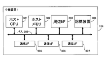
- the relay device 1_104 includes a host CPU (Central Processing Unit) 301 that performs various processes, a host memory 302, a peripheral I / F 303, a storage device 304, a communication I / F 305, and a bus 306.
- the host CPU 301, the host memory 302, the peripheral I / F 310, the storage device 304, and the communication I / F 305 are communicably connected via a bus 306.
- the host CPU 301 executes a program.
- the host memory 302 is used as a working memory and a temporary buffer for input / output data when the host CPU 301 executes a program.
- the peripheral I / F 303 is an interface for connecting the relay device 1_104 to input / output devices such as a mouse, a keyboard, and a monitor, and various peripheral devices such as an external storage such as a USB (Universal Serial Bus) memory.
- input / output devices such as a mouse, a keyboard, and a monitor
- peripheral devices such as an external storage such as a USB (Universal Serial Bus) memory.
- the storage device 304 is composed of a magnetic disk device, a flash ROM (Read Only Memory), or the like.
- the OS various drivers, various application programs, and various information used in the programs (for example, set by an administrator or a maintenance person) Stored information).
- the storage device 304 of the relay device 1_104 of this embodiment stores a route table valid period management table 209 and a plurality of route tables 210.
- the packet transmission / reception processing unit 204, the transfer destination address resolution unit 205, the time stamp generation unit 206, the route table management unit 207, and the table management packet processing unit 208 execute a program stored in the storage device 304 by the host CPU 301. It is realized by. In the following description, the processing executed by each unit described above is actually executed by the host CPU 301.
- the communication I / F 305 to the communication I / F 307 provide interfaces when the relay device 1_104 communicates with a communication device, another relay device, a route table management server, or the like via a business network or a management network.
- the communication I / F 305 may be, for example, a NIC (Network Interface Card). Although only three communication I / Fs 305 are illustrated in FIG. 3, the relay device 1_104 may have two or less communication I / Fs 305 or four or more.
- relay device 2_105 Since the functional configuration and hardware configuration of the relay device 2_105, the relay device 3_106, and the relay device 4_107 may be the same as those of the relay device 1_104, description thereof will be omitted.
- the route table effective period management table 209 stores a route table number 401, an effective period (start) 402, and an effective period (end) 403.
- the information in this table is set in advance by the administrator or maintenance person of the relay apparatus 1_104 at the time of shipment, or is distributed from the route table management server 113 via the management network e112.
- the column of the route table number 401 is an area storing IDs for uniquely identifying a plurality of route tables 210 held in the relay device 1_104.
- the column of the valid period (start) 402 is an area that stores the start date and time of the valid period of each route table.
- the column of the valid period (end) 403 is an area storing the end date and time of the valid period of each route table.
- the effective period can represent not only a period from a specific date to a date, but also a plurality of periods or periodic periods by using an asterisk (*) notation and a comma (,). .
- the route table 210 with the route table number “1” is valid for five years from January 1, 2000 to December 31, 2004, and the row 405 shows the route with the route table number “2”.
- the table 210 indicates that it is valid for five years from January 1, 2005 to December 31, 2009.
- the row 406 indicates that the route table 210 of the route table number “3” has a time zone from 13:00 to 14:00 on January 1, 2010 and from 13:00 to 14:00 on January 2, 2010. It is valid for the time zone.
- a row 407 indicates that the route table 210 with the route table number “4” is effective every day from 8:00 to 10:00.
- the notation in year / month / millisecond units is used. However, a time that is less than microseconds, a day of the week, a regular expression or a mathematical expression is used. It may be expressed.
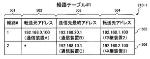
- the route table # 1_210-1 (FIG. 5A) and the route table # 2_210-2 (FIG. 5B) are examples of the two route tables 210 held by the relay device 1_104.
- the route table numbers are “1” and “ 2 ”. These route table numbers correspond to the route table number 401 of the route table valid period management table 209.
- Each route table 210 stores a route number 501, a transfer source address 502, a destination final address 503, and a transfer destination address 504.
- the information in this table is set in advance by the administrator or maintenance person of the relay apparatus 1_104 at the time of shipment, or is distributed from the route table management server 113 via the management network e112.
- the column of the route number 501 is an area for storing an ID for uniquely identifying each transfer rule (that is, correspondence between the address information of the received packet and the transfer destination address) in the route table.
- the route number 501 is assigned so as to be unique within the relay device, and each relay device searches for the transfer destination address using the address information of the received packet as a key.
- the route number is unique throughout the system. May be assigned so that the route number is embedded in the packet to be transferred, and each relay device may search for the transfer destination address using the route number as a key.
- the column of the transfer source address 502 is an area in which address information of the transfer source device of the received packet is stored.
- the transfer source device is a device that directly communicates with the relay device 1_104.
- the transfer source device is the communication device A101, the relay device 2_105, or the relay device 3_106.
- the IP address is described here as the address information, a port number may be added, or other information for uniquely identifying the transfer source such as a MAC address or a node ID uniquely assigned instead of the IP address. May be used.
- the column of the destination final address 503 is an area that stores address information indicating the final destination of the received packet.
- the IP address is described here as the address information, a port number may be added, or other information that uniquely identifies the final destination, such as a MAC address or a uniquely assigned node ID instead of the IP address. May be used.
- the column of transfer destination address 504 is an area in which address information indicating the next transfer destination is stored.
- IP address is described here as the address information, a port number may be added, or other information for uniquely identifying the transfer destination such as a MAC address or a uniquely assigned node ID instead of the IP address. May be used.
- the row 505 of the route table # 1 indicates that when the relay device 1_104 receives a packet addressed to the communication device B102 from the communication device A101, the packet is transferred to the relay device 2_105. Regardless of this, when the relay device 1_104 receives a packet addressed to the communication device C103, this indicates that the packet is transferred to the relay device 3_106. Similarly to the row 505, the row 507 of the route table # 2 indicates that even when the relay device 1_104 receives a packet addressed to the communication device B102 from the communication device A101, the packet is transferred to the relay device 3_106. Yes.
- the route table # 1 is made valid and a failure occurs in the relay device 2_105.
- the relay device 1_104 of the present embodiment needs to hold at least information that associates the destination final address, the transfer destination address, and the valid period of the combination thereof.
- the tables shown in FIGS. 4, 5A and 5B are merely examples of such information, and these tables can be replaced by another form of table containing the above information or any form of data.
- the relay apparatus 1_104 may not hold the route table valid period management table 209, but may hold only one route table 210, and each row of the route table 210 may further include information on the valid period.
- one route table 210 includes rows 505, 506, and 507, and the row 505 further includes information indicating a validity period from January 1, 2000 to December 31, 2004, Line 506 further includes information indicating the validity period from January 1, 2000 to December 31, 2009, and line 507 represents the validity period from January 1, 2005 to December 31, 2009. Information to be displayed may be further included.
- the relay device 2_105, the relay device 3_106, and the relay device 4_107 also hold a route table valid period management table and a plurality of route tables. Since the structures of these tables may be the same as those shown in FIGS. 4, 5A and 5B, the illustration and detailed description thereof will be omitted. However, the contents of the routing tables corresponding to the same effective period held by the respective relay apparatuses need to be consistent with each other.
- the relay device 1_104 determines the validity period (from January 1, 2000 to December 31, 2004) of the packet addressed to the communication device B102 from the communication device A101.
- the address of the relay device 2_105 is held as information designating a transfer destination corresponding to “first period” (see lines 404 and 505).
- the relay device 1_104 has information for designating a transfer destination corresponding to a valid period of a similar packet from January 1, 2005 to December 31, 2009 (hereinafter also referred to as “second period”).
- the address of the relay device 3_106 is held (see lines 405 and 507).
- the relay apparatus 1_104 transfers a packet addressed to the communication apparatus B102 from the communication apparatus A101 including the time stamp within the first period to the relay apparatus 2_105 (detailed procedure will be described later). For this reason, the relay device 2_105 transmits at least information (for example, the address of the communication device B102) specifying the transfer destination of the packet addressed to the communication device B102 from the communication device A101 corresponding to the first period, for example, the route table valid period. Must be kept in the management table and routing table. On the other hand, the relay device 3_106 does not need to hold the information specifying the packet transfer destination corresponding to the first period.
- the relay device 3_106 does not need to hold the information specifying the packet transfer destination corresponding to the first period.
- the relay device 1_104 transfers the packet including the time stamp in the second period to the relay device 3_106 without transferring the packet to the relay device 2_105.
- the relay device 2_105 does not need to hold the information for designating the packet transfer destination similar to the above corresponding to the second period, but the relay device 3_106 corresponds to at least the second period. It is necessary to hold information (for example, the address of the relay device 4_107) that designates a transfer destination of a packet addressed to the communication device B102 from the communication device A101.
- the route information corresponding to each valid period held by each relay apparatus is matched with each other by including information for causing a packet including a time stamp within each valid period to reach the final destination communication apparatus. Need to be. New registration and update of the route table (see FIGS. 8 and 11), which will be described later, are executed so that the contents of the route table held by each relay device are consistent with each other.
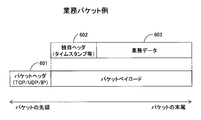
- the business packet is roughly composed of a packet header 601 and a packet payload, and the packet payload is composed of a unique header 602 and business data 603.
- the packet header 601 stores header information necessary for general-purpose communication protocols such as TCP / IP, UDP / IP, and Ethernet.
- the unique header 602 stores information necessary for resolving the transfer destination address such as a time stamp, a path number, and a final destination address.
- the business data 603 stores part or all of the business message.
- the information stored in the unique header 602 may be replaced with a standard item of the general-purpose packet header 601 or may be stored in an extended area. In this case, the area of the unique header 602 may be unnecessary.
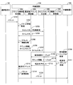
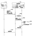
- the communication device A101 transmits a packet to the relay device 1_104 (step S701).
- the packet transmission / reception processing unit 204 of the relay device 1_104 performs reception processing of the packet received via the NIC 202 and reconstructs the packetized business message (step S702). If a time stamp is stored in the received packet, the process proceeds to step S705. If a time stamp is not stored in the received packet, the packet transmission / reception processing unit 204 makes a time stamp acquisition request to the time stamp generation unit 206 in order to acquire the time at the time of reception (step S703). A stamp is acquired (step S704).
- the packet transmission / reception processing unit 204 acquires transfer source address information and transmission destination final address information from the received packet (step S705). Such address information is stored in an IP header or a unique header.
- the packet transmission / reception processing unit 204 passes the time stamp and the address information to the transfer destination address resolution unit 205 (step S706).
- the transfer destination address resolution unit 205 passes the time stamp to the route table management unit 207 (step S707).
- the route table management unit 207 refers to the route table validity period management table 209, searches for a valid route table number based on the passed time stamp (step S708), and transfers the hit route table number list to the transfer destination address resolution unit. It passes to 205 (step S709).
- the transfer destination address resolution unit 205 passes the address information passed in step S706 and the valid route table number to the route table management unit 207 (step S710).
- the route table management unit 207 transfers the transfer destination address corresponding to the address information passed in step S706 from the route table 210 specified by the valid route table number passed in step S710 (ie, the received packet).
- the transfer destination address 504 value corresponding to the same destination final address 503 as the destination destination address information included is acquired (step S711) and passed to the transfer destination address resolution unit 205 (step S712). Steps S710 to S712 are repeatedly executed for the number of valid route tables.
- the transfer destination address resolution unit 205 passes the transfer destination address list to the packet transmission / reception processing unit 204 (step S713).
- the packet transmission / reception processing unit 204 creates a transmission packet for each transferred transfer destination address (step S714), and transmits the packet to each transfer destination via the NIC 202 or 203 (step S715).
- the route table management server 113 transmits a registration request packet to the relay device 1_104 (step S801).
- This packet includes registration target route table information and a valid period.
- the table management packet processing unit 208 of the relay apparatus 1_104 performs reception processing of the packet received via the NIC 201, and reconstructs the packetized route table registration message (step S802). Then, the table management packet processing unit 208 passes the route table to be registered and the valid period to the route table management unit 207 (step S803).
- the route table management unit 207 newly registers a route table (step S804), newly registers the effective period of the registered route table in the route table effective period management table (step S805), and manages the registration result as a table.
- the packet is transferred to the packet processing unit 208 (step S806).
- the table management packet processing unit 208 returns the registration result to the route table management server 113 (step S807).
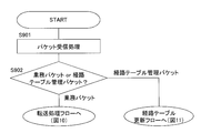
- FIG. 9 is an overall flowchart of the relay apparatus 1_104.
- step S901 the packet transmission / reception processing unit 204 or the table management packet processing unit 208 performs reception processing.
- step S902 the relay device 1_104 determines whether the received packet is a business packet or a routing table management packet. If it is a business packet, the flow proceeds to a transfer processing flow (FIG. 9), and if it is a management packet, the flow proceeds to a route table update flow (FIG. 10).
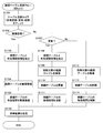
- FIG. 10 is a transfer processing flow of the relay device 1_104.
- step S1001 the packet transmission / reception processing unit 204 checks the time stamp of the received packet.
- step S1002 the packet transmission / reception processing unit 204 determines whether there is a time stamp. If the time stamp is stored, the process proceeds to step S1004. If the time stamp is not stored, the process proceeds to step S1003.
- step S1003 the packet transmission / reception processing unit 204 requests the time stamp generating unit 206 for a time stamp in the current apparatus and acquires it. Thereafter, the time stamp acquired in this step is given to the packet as the time stamp of the business message and transferred to the final destination.
- step S1004 the packet transmission / reception processing unit 204 acquires transfer source address information and final transmission destination address information from the packet header or unique header of the received packet.
- the address information acquired in this step is a key for searching for transfer destination address information from the route table 210.
- step S1005 the packet transmission / reception processing unit 204 passes the time stamp and the address information acquired from the received packet to the transfer destination address resolution unit 205 in order to acquire the transfer destination address. Then, the transfer destination address resolution unit 205 first passes the time stamp to the route table management unit 207 and searches for a valid route table list.
- step S1006 the transfer destination address resolution unit 205 checks whether there is a valid route table 210 (that is, the route table 210 corresponding to the valid period including the time of the time stamp passed from the packet transmission / reception processing unit 204). If no valid route table 210 exists, the process proceeds to step S1101. If one or more valid route tables 210 exist, the process proceeds to step S1007.
- step S1007 the transfer destination address resolution unit 205 passes the route table number and the address information acquired from the received packet to the route table management unit 207, and searches for a transfer destination address corresponding to each route table. Specifically, a transfer destination address 504 corresponding to the same destination final address 503 as the destination final address information included in the received packet is searched from the valid route table 210.
- step S1008 the transfer destination address resolution unit 205 checks whether or not there is a transfer destination address obtained by the search in step S1007. If the forwarding address does not hit any valid route table 210, the process proceeds to step S1101. If the transfer destination address is hit in one or more route tables 210, the transfer destination address resolution unit 205 passes the hit transfer destination address list to the packet transmission / reception processing unit 204, and the process proceeds to step S1009.
- step S1009 the packet transmission / reception processing unit 204 creates a transmission packet for each transfer destination address.
- the packet transmission / reception processing unit 204 stores, in a packet header or a unique header, information necessary for transfer processing in the relay device through which the packet passes before reaching the destination communication device, such as a time stamp.
- step S1010 the packet transmission / reception processing unit 204 transmits a packet to each transfer destination.
- step S1011 since the forwarding address cannot be resolved, the business message received by the packet transmission / reception processing unit 204 is discarded.
- FIG. 11 is a route table update processing flow of the relay device 1_104.
- step S1101 the table management packet processing unit 208 checks the message type (new registration, update, or deletion) of the management message received from the routing table management server 113.
- step S1102 the table management packet processing unit 208 confirms whether the message type is new registration. If the message type is new registration, the process proceeds to step S1103. If the message type is other than new registration, the process proceeds to step S1107.
- step S1103 the table management packet processing unit 208 acquires information on the route table newly registered and the validity period, and passes them to the route table management unit 207.
- step S1104 the route table management unit 207 newly creates a route table and registers route information.
- step S1105 the route table management unit 207 newly registers the validity period information of the added route table in the route table validity period management table. Then, the route table management unit 207 passes the registration result to the table management packet processing unit 208.
- step S 1106 the table management packet processing unit 208 returns a table update result to the route table management server 113.
- step S1107 the table management packet processing unit 208 checks whether the message type is update. If the message type is update, the process proceeds to step S1108; otherwise, the process proceeds to step S1112.
- step S1108 the table management packet processing unit 208 acquires the information and valid period of the route table to be updated, and passes them to the route table management unit 207.
- step S1109 the route table management unit 207 searches for a route table to be updated.
- step S1110 the route table management unit 207 updates route information for the route table to be updated.
- step S1111 the route table management unit 207 updates the validity period information of the route table to be updated in the route table validity period management table.
- step S1112 the route table management unit 207 searches for a route table to be deleted.
- step S1113 the route table management unit 207 deletes the route table to be deleted.
- step S1114 the route table management unit 207 deletes the validity period information of the route table to be deleted from the route table validity period management table.
- the routing table of each relay device is, for example, when a failure occurs or when an instruction from an external controller is received. Can be switched to.
- the route table # 1_210-1 of the relay device 1_104 is switched to the route table # 2_210-2 at midnight on January 1, 2005.
- the route tables held by each of relay device 2_105 to relay device 4_107 also match from route table # 1_210-1 to route table # 2_210-2 at midnight on January 1, 2005. Can be switched to.
- the relay apparatus 1_104 when the relay apparatus 1_104 receives a packet addressed to the communication apparatus B102 from the communication apparatus A101 before midnight on January 1, 2005, the relay apparatus 1_104 transfers the packet based on the route table # 1_210-1.
- the destination is determined as the relay device 2_105 and transmitted.
- the relay device 2_105 determines the transfer destination of the packet in order to determine the transfer destination of the packet. Refers to the route table that matches Since this does not match the routing table # 1_210-1, there is a possibility that the information specifying the transfer destination of the packet addressed from the communication apparatus A101 to the communication apparatus B102 may not be included.
- the relay apparatus 2_105 cannot determine the transfer destination of the received packet and may discard the packet.
- the same problem as described above may occur due to a difference in time when the instruction reaches each relay apparatus.
- the relay device 1_104 when the relay device 1_104 receives a packet addressed to the communication device B102 from the communication device A101 before midnight on January 1, 2005, the packet includes January 1, 2005. Includes time stamps before midnight on the day. When the received packet does not include a time stamp, the relay apparatus 1_104 gives a time stamp of a time before midnight on January 1, 2005. Then, relay device 1_104 determines the transfer destination of the packet as relay device 2_105 based on route table # 1_210-1 corresponding to this time stamp, and transmits it.
- the time stamp included in the packet is referred to without being changed in all the relay devices through which the packet reaches the communication device B102 which is the final transmission destination. Therefore, even if the time when the packet is received is after midnight on January 1, 2005, the relay device 2_105 matches the routing table # 1_210-1 to determine the transfer destination of the packet. Refer to the route table. As a result, the transfer destination of the packet can be determined with certainty.
- the route table valid period management table 209 may be created so that at least a part of the valid periods of the plurality of route tables 210 overlap. This makes it possible to easily transfer one transmission packet to a plurality of routes simultaneously.
- the communication apparatus A 101 that is the transmission source of a packet normally transmits a packet including a time stamp indicating a transmission time, but can also add a time stamp indicating another time to the packet. .
- the communication device A 101 has the scheduled time.
- the packet can be transmitted with a time stamp of the scheduled time zone assigned to the packet in a time zone where the communication cost is lower than the time zone or a time zone where the communication load is low.
- a flexible transmission schedule can be easily realized.
- each route table 210 is held by the route table validity period management table 209.
- This valid period is only an example of a condition to which the route information included in each route table 210 (specifically, at least a combination of the transmission destination final address 503 and the transfer destination address 504) is applied. There may be a variation in which conditions other than the validity period are defined. Hereinafter, typical modifications will be described.
- each route table 210 may hold information indicating the version of route information as the above condition.
- the route table # 1_210-1 may hold version information “1”
- the route table # 2_210-2 may hold version information “2”.
- the communication apparatus A101 transmits a packet including version information.
- the relay device 1_104 transfers the packet based on the route table # 1_210-1 if the version information included in the received packet is “1”, and based on the route table # 2_210-2 if the version information is “2”. Determine the destination.
- each route table 210 may include information indicating a position range to which each route table 210 is applied as the above condition.
- the position range to which the route table # 1_210-1 is applied is referred to as a first position range
- the position range to which the route table # 2_210-2 is applied is referred to as a second position range.
- the communication device A101 is a mobile communication device, and transmits a packet including the current position information of the communication device A101.
- the relay device 1_104 determines the transfer destination of the packet based on the route table # 1_210-1, and determines the position within the second position range.
- the transfer destination of the packet is determined based on the route table # 2_210-2.
- the above-described position range may be managed by a table different from the route table 210, such as the route table validity period management table 209.
- Information such as a program, a table, and a file that realize each function of the above embodiment is a storage device such as a nonvolatile semiconductor memory, a hard disk drive, an SSD (Solid State Drive), or an IC card, an SD card, a DVD, or the like. It can be stored on a computer readable non-transitory data storage medium.
- a storage device such as a nonvolatile semiconductor memory, a hard disk drive, an SSD (Solid State Drive), or an IC card, an SD card, a DVD, or the like. It can be stored on a computer readable non-transitory data storage medium.
- the present invention is not limited to the above-described embodiment, and includes various modifications.
- the above-described embodiment has been described in detail for easy understanding of the present invention, and is not necessarily limited to one having all the configurations described.
Landscapes
- Engineering & Computer Science (AREA)
- Computer Networks & Wireless Communication (AREA)
- Signal Processing (AREA)
- Data Exchanges In Wide-Area Networks (AREA)
Abstract
Description
本実施形態における中継装置を適用したシステム構成例について、図1を用いて説明する。
次に、中継装置1_104の機能構成について図2を用いて説明する。
次に、中継装置1_104のハードウェア構成について、図3を用いて説明する(適宜、図2参照)。
次に、経路テーブル有効期間管理テーブル209に格納される情報について、図4を用いて説明する。
次に、経路テーブル210に格納される情報について、図5Aおよび図5Bを用いて説明する。
次に図6を用いて、通信装置間でやりとりされる業務パケットの構成について説明する。
次に、図7を用いて、中継装置1_104が通信装置A101から受信した業務メッセージを中継装置2_105に転送する場合の一連の処理シーケンスについて説明する。
次に、図8を用いて、経路テーブル管理サーバ113が中継装置1_104の経路テーブルを新規に登録する場合の一連の処理シーケンスについて説明する。
次に、図9~図11を用いて中継装置1_104がパケットを受信した場合の処理フローについて説明する。これらは、図7および図8に示した中継装置1_104の処理を詳細に説明するものである。
図10は、中継装置1_104の転送処理フローである。
図11は、中継装置1_104の経路テーブル更新処理フローである。
図1に示す通信システムにおいて本発明の代わりに従来の技術が適用される場合、各中継装置の経路テーブルは、例えば、障害が発生したとき、または、外部のコントローラからの指示を受けたとき等に切り替えられる。ここで、中継装置1_104の経路テーブル#1_210-1が、2005年1月1日午前0時に経路テーブル#2_210-2へと切り替えられると仮定する。この場合、中継装置2_105~中継装置4_107のそれぞれが保持する経路テーブルも、2005年1月1日午前0時に、経路テーブル#1_210-1に整合するものから経路テーブル#2_210-2に整合するものへと切り替えられる。
本実施形態では、各経路テーブル210の有効期間を示す情報が経路テーブル有効期間管理テーブル209によって保持される。この有効期間は、各経路テーブル210に含まれる経路情報(具体的には少なくとも送信先最終アドレス503と転送先アドレス504との組)が適用される条件の一例に過ぎず、本実施形態には有効期間以外の条件が定義される変形例があり得る。以下、代表的な変形例を説明する。
Claims (10)
- ネットワークに接続される一つ以上の通信インタフェースと、前記一つ以上の通信インタフェースに接続されるプロセッサと、前記プロセッサに接続されるメモリと、を有し、
パケットの最終宛先と次の転送先との複数の組を含む経路情報と、前記経路情報の各組を適用する条件と、を保持し、
受信したパケットに含まれる情報に基づいて、前記受信したパケットが前記経路情報の各組を適用する条件を満たすか否かを判定し、
満たされると判定された前記条件に対応し、かつ、前記受信したパケットに含まれる最終宛先情報と一致する前記パケットの最終宛先を含む一つ以上の前記経路情報の組に含まれる一つ以上の前記次の転送先に、前記受信したパケットを転送することを特徴とするパケット中継装置。 - 請求項1に記載のパケット中継装置であって、
前記経路情報の各組を適用する条件は、前記経路情報の各組の有効期間であり、
前記受信したパケットに含まれる時刻情報が、前記経路情報の各組の有効期間内の時刻を示す場合、前記受信したパケットが前記経路情報の各組を適用する条件を満たすと判定することを特徴とするパケット中継装置。 - 請求項2に記載のパケット中継装置であって、
前記受信したパケットに時刻情報が含まれない場合、新たな時刻情報を、前記受信したパケットに含まれるように追加し、
前記受信したパケットに含まれる時刻情報を変更せずに、前記受信したパケットを前記一つ以上の次の転送先に転送することを特徴とするパケット中継装置。 - パケット中継装置が実行するパケット転送方法であって、
前記パケット中継装置は、
ネットワークに接続される一つ以上の通信インタフェースと、前記一つ以上の通信インタフェースに接続されるプロセッサと、前記プロセッサに接続されるメモリと、を有し、
パケットの最終宛先と次の転送先との複数の組を含む経路情報と、前記経路情報の各組を適用する条件と、を保持し、
前記転送方法は、
受信したパケットに含まれる情報に基づいて、前記受信したパケットが前記経路情報の各組を適用する条件を満たすか否かを判定する第1手順と、
満たされると判定された前記条件に対応し、かつ、前記受信したパケットに含まれる最終宛先情報と一致する前記パケットの最終宛先を含む一つ以上の前記経路情報の組に含まれる一つ以上の前記次の転送先に、前記受信したパケットを転送する第2手順と、を含むことを特徴とするパケット転送方法。 - 請求項4に記載のパケット転送方法であって、
前記経路情報の各組を適用する条件は、前記経路情報の各組の有効期間であり、
前記第1手順において、前記パケット中継装置は、前記受信したパケットに含まれる時刻情報が、前記経路情報の各組の有効期間内の時刻を示す場合、前記受信したパケットが前記経路情報の各組を適用する条件を満たすと判定することを特徴とするパケット転送方法。 - 請求項5に記載のパケット転送方法であって、
前記受信したパケットに時刻情報が含まれない場合、新たな時刻情報を、前記受信したパケットに含まれるように追加する第3手順をさらに含み、
前記第2手順において、前記パケット中継装置は、前記受信したパケットに含まれる時刻情報を変更せずに、前記受信したパケットを前記一つ以上の次の転送先に転送することを特徴とするパケット転送方法。 - 複数のパケット中継装置と、ネットワークを介して各々がいずれかの前記パケット中継装置に接続される複数の通信装置と、を有する通信システムであって、
前記各パケット中継装置は、
パケットの最終宛先と次の転送先との複数の組を含む経路情報と、前記経路情報の各組を適用する条件とを、前記複数のパケット中継装置が保持する同一の前記条件に対応する前記経路情報の組が互いに整合するように保持し、
受信したパケットに含まれる情報に基づいて、前記受信したパケットが前記経路情報の各組を適用する条件を満たすか否かを判定し、
満たされると判定された前記条件に対応し、かつ、前記受信したパケットに含まれる最終宛先情報と一致する前記パケットの最終宛先を含む一つ以上の前記経路情報の組に含まれる一つ以上の前記次の転送先に、前記受信したパケットを転送することを特徴とする通信システム。 - 請求項7に記載の通信システムであって、
前記経路情報の各組を適用する条件は、前記経路情報の各組の有効期間であり、
前記各パケット中継装置は、前記受信したパケットに含まれる時刻情報が、前記経路情報の各組の有効期間内の時刻を示す場合、前記受信したパケットが前記経路情報の各組を適用する条件を満たすと判定することを特徴とする通信システム。 - 請求項8に記載の通信システムであって、
前記各通信装置は、時刻情報を含むパケットを、前記各通信装置に接続されたパケット中継装置に送信し、
前記各パケット中継装置は、前記通信装置又は他の前記パケット中継装置から受信したパケットに含まれる時刻情報を変更せずに、前記受信したパケットを前記一つ以上の次の転送先に転送することを特徴とする通信システム。 - 請求項8に記載の通信システムであって、
前記各通信装置は、時刻情報を含まないパケットを、前記各通信装置に接続されたパケット中継装置に送信し、
前記各通信装置から前記パケットを受信した前記パケット中継装置は、前記受信したパケットに新たな時刻情報を追加し、前記追加した時刻情報を含む前記受信したパケットを前記一つ以上の次の転送先に転送し、
他の前記パケット中継装置から前記追加した時刻情報を含むパケットを受信した前記パケット中継装置は、前記受信したパケットに含まれる時刻情報を変更せずに、前記受信したパケットを前記一つ以上の次の転送先に転送することを特徴とする通信システム。
Priority Applications (4)
| Application Number | Priority Date | Filing Date | Title |
|---|---|---|---|
| US14/649,344 US20150304215A1 (en) | 2012-12-28 | 2012-12-28 | Packet relay apparatus, packet transfer method, and communication system |
| PCT/JP2012/084008 WO2014102993A1 (ja) | 2012-12-28 | 2012-12-28 | パケット中継装置、パケット転送方法および通信システム |
| EP12890973.6A EP2940945A4 (en) | 2012-12-28 | 2012-12-28 | PACKAGE AMPLIFIER, PACKET TRANSFER PROCESS AND COMMUNICATION SYSTEM |
| JP2014553984A JP5941556B2 (ja) | 2012-12-28 | 2012-12-28 | パケット中継装置、パケット転送方法および通信システム |
Applications Claiming Priority (1)
| Application Number | Priority Date | Filing Date | Title |
|---|---|---|---|
| PCT/JP2012/084008 WO2014102993A1 (ja) | 2012-12-28 | 2012-12-28 | パケット中継装置、パケット転送方法および通信システム |
Publications (1)
| Publication Number | Publication Date |
|---|---|
| WO2014102993A1 true WO2014102993A1 (ja) | 2014-07-03 |
Family
ID=51020144
Family Applications (1)
| Application Number | Title | Priority Date | Filing Date |
|---|---|---|---|
| PCT/JP2012/084008 Ceased WO2014102993A1 (ja) | 2012-12-28 | 2012-12-28 | パケット中継装置、パケット転送方法および通信システム |
Country Status (4)
| Country | Link |
|---|---|
| US (1) | US20150304215A1 (ja) |
| EP (1) | EP2940945A4 (ja) |
| JP (1) | JP5941556B2 (ja) |
| WO (1) | WO2014102993A1 (ja) |
Cited By (3)
| Publication number | Priority date | Publication date | Assignee | Title |
|---|---|---|---|---|
| JP2018125607A (ja) * | 2017-01-30 | 2018-08-09 | 古河電気工業株式会社 | ノード装置およびその制御方法 |
| JP2019200698A (ja) * | 2018-05-18 | 2019-11-21 | 日本電信電話株式会社 | パケット処理装置及びそのメモリアクセス制御方法 |
| JP2021504983A (ja) * | 2017-11-28 | 2021-02-15 | ホアウェイ・テクノロジーズ・カンパニー・リミテッド | メッセージ転送方法、制御プレーンゲートウェイおよびユーザプレーンゲートウェイ |
Families Citing this family (1)
| Publication number | Priority date | Publication date | Assignee | Title |
|---|---|---|---|---|
| US10361899B2 (en) | 2015-09-30 | 2019-07-23 | Nicira, Inc. | Packet processing rule versioning |
Citations (5)
| Publication number | Priority date | Publication date | Assignee | Title |
|---|---|---|---|---|
| JP2000209271A (ja) | 1999-01-18 | 2000-07-28 | Nec Corp | ル―タ装置 |
| JP2004297265A (ja) * | 2003-03-26 | 2004-10-21 | Hitachi Kokusai Electric Inc | パケット伝送システム |
| JP2005159501A (ja) * | 2003-11-21 | 2005-06-16 | Yokogawa Electric Corp | パケット選別装置 |
| JP2008131240A (ja) * | 2006-11-20 | 2008-06-05 | Fujitsu Ltd | ネットワークシステム、その装置及び方法 |
| WO2010142356A1 (en) * | 2009-06-09 | 2010-12-16 | Telefonaktiebolaget Lm Ericsson (Publ) | Packet forwarding in a network |
Family Cites Families (10)
| Publication number | Priority date | Publication date | Assignee | Title |
|---|---|---|---|---|
| JPH08191328A (ja) * | 1995-01-09 | 1996-07-23 | Oki Electric Ind Co Ltd | 自動方路選択装置 |
| JP3601393B2 (ja) * | 2000-01-11 | 2004-12-15 | 日本電気株式会社 | データグラム中継装置及びその方法 |
| JP3833450B2 (ja) * | 2000-07-27 | 2006-10-11 | 三菱電機株式会社 | 通信制御方式及びルータ |
| JP2004266342A (ja) * | 2003-02-03 | 2004-09-24 | Sony Corp | 無線アドホック通信システム、端末、その端末における復号方法、暗号化方法及びブロードキャスト暗号鍵配布方法並びにそれらの方法を端末に実行させるためのプログラム |
| KR20050114654A (ko) * | 2003-03-13 | 2005-12-06 | 소니 가부시끼 가이샤 | 무선 애드 혹 통신 시스템, 단말기, 그 단말기에 있어서의처리 방법 및 그 방법을 단말기에 실행하도록 하기 위한프로그램 |
| US7620732B2 (en) * | 2003-11-18 | 2009-11-17 | Kabushiki Kaisha Toshiba | Apparatus for and method of setting communication path |
| DE602004025280D1 (de) * | 2003-12-17 | 2010-03-11 | Nec Corp | Netzwerk, routereinrichtung, routenaktualisierungs-unterdrückungsverfahren dafür und programm dafür |
| JP4090482B2 (ja) * | 2005-12-27 | 2008-05-28 | ソフトバンクテレコム株式会社 | ネットワーク接続装置、ネットワーク接続システム、ネットワーク接続方法、及びネットワーク接続処理プログラム |
| WO2007114183A1 (ja) * | 2006-03-31 | 2007-10-11 | Matsushita Electric Industrial Co., Ltd. | ネットワーク中継装置、データ受信装置、データ送信装置、マルチ経路mtu発見方法並びにマルチ経路mtu発見システム |
| EP2055056B1 (de) * | 2006-08-24 | 2009-12-30 | Siemens Aktiengesellschaft | Verfahren und netzwerkknoten zum routen von datenpaketen in kommunikationsnetzen |
-
2012
- 2012-12-28 EP EP12890973.6A patent/EP2940945A4/en not_active Withdrawn
- 2012-12-28 US US14/649,344 patent/US20150304215A1/en not_active Abandoned
- 2012-12-28 WO PCT/JP2012/084008 patent/WO2014102993A1/ja not_active Ceased
- 2012-12-28 JP JP2014553984A patent/JP5941556B2/ja not_active Expired - Fee Related
Patent Citations (5)
| Publication number | Priority date | Publication date | Assignee | Title |
|---|---|---|---|---|
| JP2000209271A (ja) | 1999-01-18 | 2000-07-28 | Nec Corp | ル―タ装置 |
| JP2004297265A (ja) * | 2003-03-26 | 2004-10-21 | Hitachi Kokusai Electric Inc | パケット伝送システム |
| JP2005159501A (ja) * | 2003-11-21 | 2005-06-16 | Yokogawa Electric Corp | パケット選別装置 |
| JP2008131240A (ja) * | 2006-11-20 | 2008-06-05 | Fujitsu Ltd | ネットワークシステム、その装置及び方法 |
| WO2010142356A1 (en) * | 2009-06-09 | 2010-12-16 | Telefonaktiebolaget Lm Ericsson (Publ) | Packet forwarding in a network |
Non-Patent Citations (2)
| Title |
|---|
| OPENFLOW SWITCH SPECIFICATION VERSION 1.1.0 IMPLEMENTED, 28 February 2011 (2011-02-28), Retrieved from the Internet <URL:http: / jwww.openflow.orgjdocumentsjopenflow-spec-v1.1.0.pdf> |
| See also references of EP2940945A4 |
Cited By (5)
| Publication number | Priority date | Publication date | Assignee | Title |
|---|---|---|---|---|
| JP2018125607A (ja) * | 2017-01-30 | 2018-08-09 | 古河電気工業株式会社 | ノード装置およびその制御方法 |
| JP2021504983A (ja) * | 2017-11-28 | 2021-02-15 | ホアウェイ・テクノロジーズ・カンパニー・リミテッド | メッセージ転送方法、制御プレーンゲートウェイおよびユーザプレーンゲートウェイ |
| JP7065034B2 (ja) | 2017-11-28 | 2022-05-11 | ホアウェイ・テクノロジーズ・カンパニー・リミテッド | メッセージ転送方法、制御プレーンゲートウェイおよびユーザプレーンゲートウェイ |
| JP2019200698A (ja) * | 2018-05-18 | 2019-11-21 | 日本電信電話株式会社 | パケット処理装置及びそのメモリアクセス制御方法 |
| JP6991446B2 (ja) | 2018-05-18 | 2022-01-12 | 日本電信電話株式会社 | パケット処理装置及びそのメモリアクセス制御方法 |
Also Published As
| Publication number | Publication date |
|---|---|
| US20150304215A1 (en) | 2015-10-22 |
| EP2940945A4 (en) | 2016-08-31 |
| JPWO2014102993A1 (ja) | 2017-01-12 |
| JP5941556B2 (ja) | 2016-06-29 |
| EP2940945A1 (en) | 2015-11-04 |
Similar Documents
| Publication | Publication Date | Title |
|---|---|---|
| JP5446040B2 (ja) | コンピュータシステム、及び仮想マシンのマイグレーション方法 | |
| JP5590263B2 (ja) | 情報システム、制御装置、仮想ネットワークの提供方法およびプログラム | |
| JP5850068B2 (ja) | 制御装置、通信システム、通信方法およびプログラム | |
| JP5754506B2 (ja) | 通信システム、コントローラ、スイッチ、ストレージ管理装置、及び通信方法 | |
| US9014088B2 (en) | System and method for delivering data in an intermittent communication environment | |
| JP4257151B2 (ja) | パケット制御システム、パケット制御装置、パケット中継装置およびパケット制御プログラム | |
| JP2019523608A (ja) | パケット監視 | |
| JP5941556B2 (ja) | パケット中継装置、パケット転送方法および通信システム | |
| JP2018093358A (ja) | 経路探索システム、経路探索方法及び経路探索プログラム | |
| US11088937B1 (en) | System and method for synchronized route update | |
| CN104508651A (zh) | 镜像非对称集群多处理器系统中的连接网 | |
| WO2014175335A1 (ja) | 制御装置、計算機システム、通信制御方法及びプログラム | |
| JPWO2014126094A1 (ja) | 通信システム、通信方法、制御装置、制御装置の制御方法及びプログラム | |
| JP6379702B2 (ja) | データ転送システム、データ転送サーバ、データ転送方法、および、プログラム | |
| EP2645677B1 (en) | A method and a network element for content based addressing in a data transfer network | |
| JP4378205B2 (ja) | ブレード型ネットワーク中継装置 | |
| JP7656108B1 (ja) | 通信処理装置、ゲートウェイ装置及び通信システム | |
| JP6062394B2 (ja) | 中継装置および中継方法 | |
| JP2008072521A (ja) | 通信装置、通信方法及び通信プログラム | |
| JP5833184B2 (ja) | ネットワーク輻輳回避システム及び方法 | |
| JP5553036B2 (ja) | 通信制御装置、通信制御方法および通信制御プログラム | |
| CN105051628B (zh) | 网络单元 | |
| JP2015220496A (ja) | データ転送方法及びデータ転送システム | |
| JP2016046755A (ja) | 通信装置、通信システム、通信制御プログラム、及び通信制御方法 | |
| JP2008148145A (ja) | 経路監視装置、経路監視方法および経路監視プログラム |
Legal Events
| Date | Code | Title | Description |
|---|---|---|---|
| 121 | Ep: the epo has been informed by wipo that ep was designated in this application |
Ref document number: 12890973 Country of ref document: EP Kind code of ref document: A1 |
|
| ENP | Entry into the national phase |
Ref document number: 2014553984 Country of ref document: JP Kind code of ref document: A |
|
| WWE | Wipo information: entry into national phase |
Ref document number: 14649344 Country of ref document: US |
|
| REEP | Request for entry into the european phase |
Ref document number: 2012890973 Country of ref document: EP |
|
| WWE | Wipo information: entry into national phase |
Ref document number: 2012890973 Country of ref document: EP |
|
| NENP | Non-entry into the national phase |
Ref country code: DE |