WO2014103111A1 - 水素生成装置及び燃料電池システム - Google Patents
水素生成装置及び燃料電池システム Download PDFInfo
- Publication number
- WO2014103111A1 WO2014103111A1 PCT/JP2013/006144 JP2013006144W WO2014103111A1 WO 2014103111 A1 WO2014103111 A1 WO 2014103111A1 JP 2013006144 W JP2013006144 W JP 2013006144W WO 2014103111 A1 WO2014103111 A1 WO 2014103111A1
- Authority
- WO
- WIPO (PCT)
- Prior art keywords
- gas
- ejector
- fuel cell
- hydrogen
- flow path
- Prior art date
- Legal status (The legal status is an assumption and is not a legal conclusion. Google has not performed a legal analysis and makes no representation as to the accuracy of the status listed.)
- Ceased
Links
Images


Classifications
-
- H—ELECTRICITY
- H01—ELECTRIC ELEMENTS
- H01M—PROCESSES OR MEANS, e.g. BATTERIES, FOR THE DIRECT CONVERSION OF CHEMICAL ENERGY INTO ELECTRICAL ENERGY
- H01M8/00—Fuel cells; Manufacture thereof
- H01M8/06—Combination of fuel cells with means for production of reactants or for treatment of residues
- H01M8/0606—Combination of fuel cells with means for production of reactants or for treatment of residues with means for production of gaseous reactants
- H01M8/0612—Combination of fuel cells with means for production of reactants or for treatment of residues with means for production of gaseous reactants from carbon-containing material
- H01M8/0618—Reforming processes, e.g. autothermal, partial oxidation or steam reforming
-
- B—PERFORMING OPERATIONS; TRANSPORTING
- B01—PHYSICAL OR CHEMICAL PROCESSES OR APPARATUS IN GENERAL
- B01J—CHEMICAL OR PHYSICAL PROCESSES, e.g. CATALYSIS OR COLLOID CHEMISTRY; THEIR RELEVANT APPARATUS
- B01J19/00—Chemical, physical or physico-chemical processes in general; Their relevant apparatus
- B01J19/24—Stationary reactors without moving elements inside
- B01J19/245—Stationary reactors without moving elements inside placed in series
-
- C—CHEMISTRY; METALLURGY
- C01—INORGANIC CHEMISTRY
- C01B—NON-METALLIC ELEMENTS; COMPOUNDS THEREOF; METALLOIDS OR COMPOUNDS THEREOF NOT COVERED BY SUBCLASS C01C
- C01B3/00—Hydrogen; Gaseous mixtures containing hydrogen; Separation of hydrogen from mixtures containing it; Purification of hydrogen; Reversible storage of hydrogen
- C01B3/02—Production of hydrogen; Production of gaseous mixtures containing hydrogen
- C01B3/32—Production of hydrogen; Production of gaseous mixtures containing hydrogen by reaction of gaseous or liquid organic compounds with gasifying agents, e.g. water, carbon dioxide or air
- C01B3/34—Production of hydrogen; Production of gaseous mixtures containing hydrogen by reaction of gaseous or liquid organic compounds with gasifying agents, e.g. water, carbon dioxide or air by reaction of hydrocarbons with gasifying agents
- C01B3/38—Production of hydrogen; Production of gaseous mixtures containing hydrogen by reaction of gaseous or liquid organic compounds with gasifying agents, e.g. water, carbon dioxide or air by reaction of hydrocarbons with gasifying agents using catalysts
-
- H—ELECTRICITY
- H01—ELECTRIC ELEMENTS
- H01M—PROCESSES OR MEANS, e.g. BATTERIES, FOR THE DIRECT CONVERSION OF CHEMICAL ENERGY INTO ELECTRICAL ENERGY
- H01M8/00—Fuel cells; Manufacture thereof
- H01M8/06—Combination of fuel cells with means for production of reactants or for treatment of residues
- H01M8/0606—Combination of fuel cells with means for production of reactants or for treatment of residues with means for production of gaseous reactants
- H01M8/0612—Combination of fuel cells with means for production of reactants or for treatment of residues with means for production of gaseous reactants from carbon-containing material
- H01M8/0625—Combination of fuel cells with means for production of reactants or for treatment of residues with means for production of gaseous reactants from carbon-containing material in a modular combined reactor/fuel cell structure
-
- H—ELECTRICITY
- H01—ELECTRIC ELEMENTS
- H01M—PROCESSES OR MEANS, e.g. BATTERIES, FOR THE DIRECT CONVERSION OF CHEMICAL ENERGY INTO ELECTRICAL ENERGY
- H01M8/00—Fuel cells; Manufacture thereof
- H01M8/06—Combination of fuel cells with means for production of reactants or for treatment of residues
- H01M8/0662—Treatment of gaseous reactants or gaseous residues, e.g. cleaning
- H01M8/0675—Removal of sulfur
-
- H—ELECTRICITY
- H01—ELECTRIC ELEMENTS
- H01M—PROCESSES OR MEANS, e.g. BATTERIES, FOR THE DIRECT CONVERSION OF CHEMICAL ENERGY INTO ELECTRICAL ENERGY
- H01M8/00—Fuel cells; Manufacture thereof
- H01M8/10—Fuel cells with solid electrolytes
- H01M8/12—Fuel cells with solid electrolytes operating at high temperature, e.g. with stabilised ZrO2 electrolyte
- H01M8/124—Fuel cells with solid electrolytes operating at high temperature, e.g. with stabilised ZrO2 electrolyte characterised by the process of manufacturing or by the material of the electrolyte
- H01M8/1246—Fuel cells with solid electrolytes operating at high temperature, e.g. with stabilised ZrO2 electrolyte characterised by the process of manufacturing or by the material of the electrolyte the electrolyte consisting of oxides
-
- B—PERFORMING OPERATIONS; TRANSPORTING
- B01—PHYSICAL OR CHEMICAL PROCESSES OR APPARATUS IN GENERAL
- B01J—CHEMICAL OR PHYSICAL PROCESSES, e.g. CATALYSIS OR COLLOID CHEMISTRY; THEIR RELEVANT APPARATUS
- B01J2219/00—Chemical, physical or physico-chemical processes in general; Their relevant apparatus
- B01J2219/00049—Controlling or regulating processes
- B01J2219/00051—Controlling the temperature
- B01J2219/00074—Controlling the temperature by indirect heating or cooling employing heat exchange fluids
- B01J2219/00087—Controlling the temperature by indirect heating or cooling employing heat exchange fluids with heat exchange elements outside the reactor
-
- B—PERFORMING OPERATIONS; TRANSPORTING
- B01—PHYSICAL OR CHEMICAL PROCESSES OR APPARATUS IN GENERAL
- B01J—CHEMICAL OR PHYSICAL PROCESSES, e.g. CATALYSIS OR COLLOID CHEMISTRY; THEIR RELEVANT APPARATUS
- B01J2219/00—Chemical, physical or physico-chemical processes in general; Their relevant apparatus
- B01J2219/24—Stationary reactors without moving elements inside
-
- C—CHEMISTRY; METALLURGY
- C01—INORGANIC CHEMISTRY
- C01B—NON-METALLIC ELEMENTS; COMPOUNDS THEREOF; METALLOIDS OR COMPOUNDS THEREOF NOT COVERED BY SUBCLASS C01C
- C01B2203/00—Integrated processes for the production of hydrogen or synthesis gas
- C01B2203/02—Processes for making hydrogen or synthesis gas
- C01B2203/0205—Processes for making hydrogen or synthesis gas containing a reforming step
- C01B2203/0227—Processes for making hydrogen or synthesis gas containing a reforming step containing a catalytic reforming step
-
- C—CHEMISTRY; METALLURGY
- C01—INORGANIC CHEMISTRY
- C01B—NON-METALLIC ELEMENTS; COMPOUNDS THEREOF; METALLOIDS OR COMPOUNDS THEREOF NOT COVERED BY SUBCLASS C01C
- C01B2203/00—Integrated processes for the production of hydrogen or synthesis gas
- C01B2203/04—Integrated processes for the production of hydrogen or synthesis gas containing a purification step for the hydrogen or the synthesis gas
- C01B2203/0435—Catalytic purification
- C01B2203/045—Purification by catalytic desulfurisation
-
- C—CHEMISTRY; METALLURGY
- C01—INORGANIC CHEMISTRY
- C01B—NON-METALLIC ELEMENTS; COMPOUNDS THEREOF; METALLOIDS OR COMPOUNDS THEREOF NOT COVERED BY SUBCLASS C01C
- C01B2203/00—Integrated processes for the production of hydrogen or synthesis gas
- C01B2203/06—Integration with other chemical processes
- C01B2203/066—Integration with other chemical processes with fuel cells
- C01B2203/067—Integration with other chemical processes with fuel cells the reforming process taking place in the fuel cell
-
- C—CHEMISTRY; METALLURGY
- C01—INORGANIC CHEMISTRY
- C01B—NON-METALLIC ELEMENTS; COMPOUNDS THEREOF; METALLOIDS OR COMPOUNDS THEREOF NOT COVERED BY SUBCLASS C01C
- C01B2203/00—Integrated processes for the production of hydrogen or synthesis gas
- C01B2203/08—Methods of heating or cooling
- C01B2203/0805—Methods of heating the process for making hydrogen or synthesis gas
-
- C—CHEMISTRY; METALLURGY
- C01—INORGANIC CHEMISTRY
- C01B—NON-METALLIC ELEMENTS; COMPOUNDS THEREOF; METALLOIDS OR COMPOUNDS THEREOF NOT COVERED BY SUBCLASS C01C
- C01B2203/00—Integrated processes for the production of hydrogen or synthesis gas
- C01B2203/12—Feeding the process for making hydrogen or synthesis gas
- C01B2203/1205—Composition of the feed
- C01B2203/1211—Organic compounds or organic mixtures used in the process for making hydrogen or synthesis gas
-
- C—CHEMISTRY; METALLURGY
- C01—INORGANIC CHEMISTRY
- C01B—NON-METALLIC ELEMENTS; COMPOUNDS THEREOF; METALLOIDS OR COMPOUNDS THEREOF NOT COVERED BY SUBCLASS C01C
- C01B2203/00—Integrated processes for the production of hydrogen or synthesis gas
- C01B2203/12—Feeding the process for making hydrogen or synthesis gas
- C01B2203/1258—Pre-treatment of the feed
- C01B2203/1264—Catalytic pre-treatment of the feed
- C01B2203/127—Catalytic desulfurisation
-
- C—CHEMISTRY; METALLURGY
- C01—INORGANIC CHEMISTRY
- C01B—NON-METALLIC ELEMENTS; COMPOUNDS THEREOF; METALLOIDS OR COMPOUNDS THEREOF NOT COVERED BY SUBCLASS C01C
- C01B2203/00—Integrated processes for the production of hydrogen or synthesis gas
- C01B2203/14—Details of the flowsheet
- C01B2203/148—Details of the flowsheet involving a recycle stream to the feed of the process for making hydrogen or synthesis gas
-
- H—ELECTRICITY
- H01—ELECTRIC ELEMENTS
- H01M—PROCESSES OR MEANS, e.g. BATTERIES, FOR THE DIRECT CONVERSION OF CHEMICAL ENERGY INTO ELECTRICAL ENERGY
- H01M8/00—Fuel cells; Manufacture thereof
- H01M8/10—Fuel cells with solid electrolytes
- H01M8/12—Fuel cells with solid electrolytes operating at high temperature, e.g. with stabilised ZrO2 electrolyte
- H01M2008/1293—Fuel cells with solid oxide electrolytes
-
- H—ELECTRICITY
- H01—ELECTRIC ELEMENTS
- H01M—PROCESSES OR MEANS, e.g. BATTERIES, FOR THE DIRECT CONVERSION OF CHEMICAL ENERGY INTO ELECTRICAL ENERGY
- H01M2250/00—Fuel cells for particular applications; Specific features of fuel cell system
- H01M2250/10—Fuel cells in stationary systems, e.g. emergency power source in plant
-
- H—ELECTRICITY
- H01—ELECTRIC ELEMENTS
- H01M—PROCESSES OR MEANS, e.g. BATTERIES, FOR THE DIRECT CONVERSION OF CHEMICAL ENERGY INTO ELECTRICAL ENERGY
- H01M2300/00—Electrolytes
- H01M2300/0017—Non-aqueous electrolytes
- H01M2300/0065—Solid electrolytes
- H01M2300/0068—Solid electrolytes inorganic
- H01M2300/0071—Oxides
- H01M2300/0074—Ion conductive at high temperature
-
- Y—GENERAL TAGGING OF NEW TECHNOLOGICAL DEVELOPMENTS; GENERAL TAGGING OF CROSS-SECTIONAL TECHNOLOGIES SPANNING OVER SEVERAL SECTIONS OF THE IPC; TECHNICAL SUBJECTS COVERED BY FORMER USPC CROSS-REFERENCE ART COLLECTIONS [XRACs] AND DIGESTS
- Y02—TECHNOLOGIES OR APPLICATIONS FOR MITIGATION OR ADAPTATION AGAINST CLIMATE CHANGE
- Y02B—CLIMATE CHANGE MITIGATION TECHNOLOGIES RELATED TO BUILDINGS, e.g. HOUSING, HOUSE APPLIANCES OR RELATED END-USER APPLICATIONS
- Y02B90/00—Enabling technologies or technologies with a potential or indirect contribution to GHG emissions mitigation
- Y02B90/10—Applications of fuel cells in buildings
-
- Y—GENERAL TAGGING OF NEW TECHNOLOGICAL DEVELOPMENTS; GENERAL TAGGING OF CROSS-SECTIONAL TECHNOLOGIES SPANNING OVER SEVERAL SECTIONS OF THE IPC; TECHNICAL SUBJECTS COVERED BY FORMER USPC CROSS-REFERENCE ART COLLECTIONS [XRACs] AND DIGESTS
- Y02—TECHNOLOGIES OR APPLICATIONS FOR MITIGATION OR ADAPTATION AGAINST CLIMATE CHANGE
- Y02E—REDUCTION OF GREENHOUSE GAS [GHG] EMISSIONS, RELATED TO ENERGY GENERATION, TRANSMISSION OR DISTRIBUTION
- Y02E60/00—Enabling technologies; Technologies with a potential or indirect contribution to GHG emissions mitigation
- Y02E60/30—Hydrogen technology
- Y02E60/50—Fuel cells
Definitions
- the present invention relates to a hydrogen generator and a fuel cell system.
- a fuel cell system In the fuel cell system, hydrogen used for fuel during power generation is not established as a general raw material infrastructure. Therefore, a fuel cell system is usually used to generate hydrogen-containing gas from city gas, natural gas, LPG, etc., which are general raw material infrastructures. Equipped with a quality device.
- a raw material gas such as city gas reacts at a high temperature of about 600 ° C. to 700 ° C. using a reforming catalyst to generate a hydrogen-containing gas containing hydrogen as a main component.
- the raw material gas contains a sulfur compound, and since this sulfur compound is a poisoning substance of the reforming catalyst, it must be removed.
- the sulfur compound can be removed from the source gas by hydrodesulfurization, for example, by mixing hydrogen gas and the source gas.
- Patent Document 1 does not examine the problem of condensed water in an ejector into which a hydrogen-containing gas from a recycle channel flows.
- the present invention has been made in view of such circumstances, and it has been suggested that there is a possibility that flow path resistance is increased due to condensed water in an ejector into which hydrogen-containing gas from a recycle flow path flows or that flow path blockage occurs. It is an object of the present invention to provide a hydrogen generator and a fuel cell system that can be further reduced.
- a hydrogen generator of one embodiment of the present invention includes a reformer that generates a hydrogen-containing gas using a raw material gas, a hydrodesulfurizer that removes a sulfur compound in the raw material gas, Provided in a recycle passage for supplying a hydrogen-containing gas to the raw material gas before flowing into the hydrodesulfurizer, and in a raw material gas passage upstream from the hydrodesulfurizer, and from the recycle passage An ejector into which the contained gas flows and a heater for heating the ejector are provided.
- the hydrogen generation device and the fuel cell system according to one aspect of the present invention have a possibility that flow path resistance may increase due to condensed water or blockage may occur in an ejector into which a hydrogen-containing gas from a recycle flow path flows. It can be reduced.
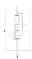
- FIG. 1 is a diagram illustrating an example of a hydrogen generator according to the first embodiment.
- FIG. 2 is a diagram illustrating an example of a hydrogen generator according to the second embodiment.
- FIG. 3 is a diagram illustrating an example of a hydrogen generator according to a first modification of the second embodiment.
- FIG. 4 is a diagram illustrating an example of a hydrogen generator according to a second modification of the second embodiment.
- FIG. 5 is a diagram showing an example of a fuel cell system according to the third embodiment.
- FIG. 6 is a diagram illustrating an example of a fuel cell system according to the fourth embodiment.
- FIG. 7 is a diagram showing an example of a fuel cell system according to the fifth embodiment.
- Recycled gas contains water vapor, so when it is cooled, condensed water is generated from the recycled gas. For example, when raw material gas lower in temperature than the recycled gas is mixed with the recycled gas, the recycled gas is cooled. Therefore, in the ejector where these gases merge, the flow resistance may increase due to condensed water, or the flow path may be blocked. There is sex.
- the hydrogen generator of the first embodiment flows into a reformer that generates a hydrogen-containing gas using a raw material gas, a hydrodesulfurizer that removes sulfur compounds in the raw material gas, and a hydrodesulfurizer.
- a recycle channel for supplying a hydrogen-containing gas to the previous source gas, a feed gas channel upstream of the hydrodesulfurizer, and an ejector into which the hydrogen-containing gas from the recycle channel flows A heater for heating.
- the ejector is heated by a heater, so even if hydrogen-containing gas flows into the ejector, the possibility of increased flow resistance or blockage of the flow path due to condensed water in the ejector is reduced compared to the conventional case. obtain.
- FIG. 1 is a diagram illustrating an example of a hydrogen generator according to the first embodiment.
- the hydrogen generator 100 of this embodiment includes a reformer 1, a hydrodesulfurizer 2, a recycle channel 3, an ejector 5, and a heater 6.
- the reformer 1 generates a hydrogen-containing gas using the raw material gas. Specifically, in the reforming catalyst section (not shown) in the reformer 1, the raw material gas undergoes a reforming reaction to generate a hydrogen-containing gas.
- the reforming reaction may take any form, and examples thereof include a steam reforming reaction, an autothermal reaction, and a partial oxidation reaction.
- equipment required for each reforming reaction is provided as appropriate. For example, if the reforming reaction is a steam reforming reaction, a combustor that heats the reforming catalyst unit, an evaporator that generates steam, and a water supplier that supplies water to the evaporator are provided.
- the hydrogen generator 100 is further provided with an air supply device that supplies air to the reformer.
- the source gas contains an organic compound composed of at least carbon and hydrogen, such as city gas mainly composed of methane, natural gas, and LPG.
- the hydrodesulfurizer 2 removes sulfur compounds in the raw material gas.
- the hydrodesulfurizer 2 is configured by filling a container with a hydrodesulfurization agent.
- a hydrodesulfurization agent for example, a CuZn-based catalyst having both a function of converting a sulfur compound into hydrogen sulfide and a function of adsorbing hydrogen sulfide is used.
- the hydrodesulfurization agent is not limited to this example, and is a CoMo-based catalyst that converts a sulfur compound in the raw material gas into hydrogen sulfide, and a sulfur adsorbent that is provided downstream thereof to adsorb and remove hydrogen sulfide. You may comprise with a ZnO type catalyst or a CuZn type catalyst.
- the recycle channel 3 is a channel for supplying a hydrogen-containing gas to the raw material gas before flowing into the hydrodesulfurizer 2.
- the upstream end of the recycle flow path 3 may be connected to any location as long as it is a flow path through which the hydrogen-containing gas sent from the reformer 1 flows.
- the upstream end of the recycle channel 2 is a flow between the reformer 1 and the CO reducer. It may be connected to a path, may be connected to a CO reducer, or may be connected downstream of the CO reducer.
- the recycle flow path 3 You may comprise so that the upstream end of may be connected to the flow path between a transformer and a CO remover. Moreover, you may connect the upstream end of the recycle flow path 3 to the flow path downstream of the apparatus (for example, fuel cell etc.) using hydrogen containing gas. Note that the hydrogen generator 100 is not necessarily provided with a CO reducer, and may be omitted as long as necessary performance can be obtained for an apparatus using the hydrogen-containing gas generated by the hydrogen generator 100.
- the ejector 5 is provided in the raw material gas flow path upstream of the hydrodesulfurizer 2, and the hydrogen-containing gas from the recycle flow path 3 flows in.
- the ejector 5 is a device that increases the flow rate of the raw material gas by narrowing the cross-sectional area of the raw material gas flow path through which the raw material gas flows, and generates a lower pressure than the low flow rate portion.
- the source gas channel is a channel through which the source gas supplied to the reformer 1 flows.
- the recycle channel 3 may be configured to merge with the source gas channel of the ejector 5 at a position where the flow rate of the source gas is maximized. At the position where the flow rate of the raw material gas is maximum, the gas pressure is the lowest. Therefore, when the gas flow path cross-sectional area of the ejector 5 is designed so that this gas pressure is lower than the upstream side of the recycle flow path 3, the hydrogen-containing gas from the recycle flow path 3 is drawn into the ejector 5. Can do. By such an action of drawing the hydrogen-containing gas by the ejector 5, a configuration in which a device (for example, a pressure reducer) for balancing the pressure is not provided in the recycle channel 3 is possible. Thereby, the structure of the hydrogen generator 100 can be simplified and the cost of the hydrogen generator 100 can be reduced.
- a device for example, a pressure reducer
- the heater 6 heats the ejector 5.
- the source gas and the hydrogen-containing gas flow. Since the hydrogen-containing gas contains water vapor, condensed water may be generated from the water vapor when the hydrogen-containing gas is cooled.
- the hydrogen-containing gas is cooled.
- the narrowed portion of the source gas flow path in the ejector 5 is likely to cause an increase in flow path resistance or blockage of the flow path due to condensed water.
- the reformer 1 When the flow resistance increases, a predetermined amount of hydrogen-containing gas cannot be sent to the hydrodesulfurizer 2, and the reformer 1 can be modified without removing the sulfur compound in the raw material gas in the hydrodesulfurizer 2.
- the quality catalyst may be poisoned by sulfur compounds.
- a predetermined amount of the raw material gas cannot be flowed, and the hydrogen-containing gas in the reformer 1 may not be generated.
- the heater 6 heats the ejector 5, thereby suppressing the water vapor of the hydrogen-containing gas from condensing in the ejector 5.
- Any heat source may be used for the heater 6 as long as the ejector 5 can be heated.
- the ejector 5 can be heated by the heat generated from the reformer 1.
- the ejector 5 may be disposed on the surface of the reformer 1, or the ejector 5 may be disposed inside the reformer 1.
- the ejector 5 can be heated by heat generated from a device that uses a hydrogen-containing gas (for example, a fuel cell).
- a hydrogen-containing gas for example, a fuel cell
- the ejector 5 may be disposed inside a hot module of the fuel cell.
- the hydrogen generator 100 is configured to include a combustor that heats the reformer 1, the ejector 5 can be heated by the heat of the combustion exhaust gas from the combustor.
- the ejector 5 can be heated using a dedicated heat source (for example, an electric heater).
- a dedicated heat source for example, an electric heater
- the raw material gas passes through the hydrodesulfurizer 2 to remove sulfur compounds in the raw material gas.
- a part of the hydrogen-containing gas generated in the reformer 1 is returned to the raw material gas flow path through the recycle flow path 3, mixed with the raw material gas, and then supplied to the hydrodesulfurizer 2.
- the hydrodesulfurizer 2 can remove sulfur compounds in the raw material gas by a hydrogenation reaction.
- the hydrogen-containing gas from the reformer 1 is supplied to the hydrodesulfurizer 2 after being mixed with the raw material gas in the ejector 5 via the recycle channel 3. That is, the mixed gas of the raw material gas and the recycled gas flows through the raw material gas passage downstream of the junction with the recycle passage 3.
- the cross-sectional area of the raw material gas flow path is gradually narrowed, and the cross-sectional area of the raw material gas flow path is gradually widened downstream of the junction with the recycle flow path 3.
- the ejector 5 when the recycle gas is drawn into the raw material gas flow path, the ejector 5 is heated using the heater 6.
- the heating temperature of the ejector 5 may be any temperature as long as it is equal to or higher than the dew point temperature of the recycled gas.
- the heating of the ejector 5 when the hydrogen generator 100 is started may be started before the recycle gas starts flowing through the recycle flow path 3, for example.
- Recycled gas contains water vapor, so when it is cooled, condensed water is generated from the recycled gas.
- the raw material gas and the recycled gas are mixed upstream of the booster, the raw material gas having a temperature lower than the recycled gas is mixed with the recycled gas. Then, since the recycled gas is cooled, the condensed water flows into the booster that is the supply destination. Then, in the booster, flow path resistance increases due to condensed water, or the flow path is blocked, which may cause a problem that an appropriate amount of gas flow cannot be supplied, or a problem that the booster fails.
- the hydrogen generator of the second embodiment is provided with a booster for supplying the raw material gas to the reformer in the hydrogen generator of the first embodiment, and the ejector is disposed in the raw material gas flow path downstream of the booster. Is provided.
- the hydrogen generator of this embodiment may be configured in the same manner as the hydrogen generator of the first embodiment except for the above features.
- FIG. 2 is a diagram illustrating an example of a fuel cell system according to the second embodiment.
- the hydrogen generator 100 of the present embodiment includes a reformer 1, a hydrodesulfurizer 2, a recycle channel 3, a booster 4, an ejector 5, and a heater 6. Prepare.
- the booster 4 supplies the raw material gas to the reformer 1.
- the raw material gas is pressurized using the booster 4. That is, in order to flow a predetermined amount of source gas, the source gas needs to be boosted to a pressure that takes into account the flow path resistance in the equipment downstream of the booster 4.
- the booster 4 may have any configuration as long as the source gas can be boosted.
- a diaphragm pump can be used as the booster 4, for example.
- the source gas is supplied from a source gas supply source.
- the source gas supply source has a predetermined supply pressure, and examples thereof include a source gas cylinder and a source gas infrastructure.
- the ejector 5 is provided in the raw material gas flow path downstream of the booster 4. Thereby, the hydrogen-containing gas from the recycle channel 3 flows into the ejector 5 downstream of the booster 4. Therefore, compared with the past, the inflow of the condensed water in the pressure
- the operation of the hydrogen generator 100 of this embodiment may be the same as that of the first embodiment. Therefore, detailed description is omitted.
- the hydrogen generator of the 1st modification of 2nd Embodiment is a hydrogen generator of 2nd Embodiment. Said heater heats a recycle channel.
- Such a configuration can reduce the possibility of an increase in channel resistance or blockage of the channel due to condensed water in the ejector.
- the possibility of an increase in channel resistance due to condensed water in the recycling channel or a blockage of the channel may be reduced as compared with the conventional case.
- the hydrogen generator of this modification may be configured in the same manner as the hydrogen generator of the second embodiment except for the above features.
- FIG. 3 is a diagram illustrating an example of a hydrogen generator according to a first modification of the second embodiment.
- the hydrogen generator 100 of the present modification includes a reformer 1, a hydrodesulfurizer 2, a recycle channel 3, a booster 4, an ejector 5, and a heater 6 ⁇ / b> A. Prepare.
- the reformer 1, the hydrodesulfurizer 2, the recycle flow path 3, the booster 4 and the ejector 5 are the same as those in the second embodiment, and thus description thereof is omitted.
- the heater 6A heats the recycling flow path 3.
- both the ejector 5 and the recycling flow path 3 are heated by the heater 6A.
- the heat source of the heater 6A may be the same as the heat source of the heater 6 of the second embodiment. Therefore, detailed description is omitted.
- the amount of heat obtained from the heater 6A of the present modification may be increased as compared with the amount of heat obtained from the heater 6 of the second embodiment by the amount required to heat the recycle flow path 3, and the heater 6
- the amount of heat equivalent to the amount of heat obtained from the above may be distributed from the heater 6A to each of the ejector 5 and the recycle flow path 3.
- the same amount of heat as that obtained from the heater 6 is distributed from the heater 6 ⁇ / b> A to the ejector 5 and the recycle channel 3.
- the total amount of heat obtained from the heater 6 of the second embodiment is equivalent. This is because it can be considered that the amount of heat is used for heating the gas in the ejector 5.
- the recycle gas can be maintained at a high temperature and drawn into the ejector 5, and the possibility that the flow path resistance is increased or the flow path is blocked by the condensed water in the ejector 5 can be reduced as compared with the conventional case.
- the temperature drop of the recycle gas which flows through the recycle flow path 3 can be suppressed, and the possibility that the flow path resistance is increased or the flow path is blocked by the condensed water in the recycle flow path 3 can be reduced as compared with the conventional case.
- due to the heating action of the recycle flow path 3 it is possible to reduce the size of the condenser even if the recycle flow path 3 is not provided with a condenser or provided. Thereby, the structure of the hydrogen generator 100 can be simplified and the cost of the hydrogen generator 100 can be reduced.
- the hydrogen generator of the second modification of the second embodiment is the hydrogen generator of any one of the second embodiment and the first modification of the second embodiment.
- the heater heats the reformer.
- Such a configuration can reduce the possibility of an increase in channel resistance or blockage of the channel due to condensed water in the ejector.
- the possibility of an increase in channel resistance due to condensed water in the recycling channel or a blockage of the channel may be reduced as compared with the conventional case.
- the amount of heat of the heater can be used efficiently.
- the hydrogen generator of this modification may be configured similarly to the hydrogen generator of any one of the second embodiment and the first modification of the second embodiment, except for the above features.
- FIG. 4 is a diagram illustrating an example of a hydrogen generator according to a second modification of the second embodiment.
- the hydrogen generator 100 of this modification includes a reformer 1, a hydrodesulfurizer 2, a recycle channel 3, a booster 4, an ejector 5, and a heater 6 ⁇ / b> B. Prepare.
- the reformer 1, the hydrodesulfurizer 2, the recycle flow path 3, the booster 4 and the ejector 5 are the same as those in the second embodiment, and thus description thereof is omitted.
- the heater 6B heats the reformer 1.
- each of the ejector 5, the recycle flow path 3, and the reformer 1 is heated by the heater 6B.
- the heat source of the heater 6B the heat of the combustion exhaust gas of the combustor that heats the reformer 1 may be used.
- the fuel Battery heat may be used.
- the reformer 1, the recycle channel 3, and the ejector 5 can be heated together.
- heat necessary for the catalytic reaction for generating the hydrogen-containing gas is obtained.
- the possibility that the flow path resistance is increased or the flow path is blocked by the condensed water in the ejector 5 due to the heating of the ejector 5 can be reduced as compared with the conventional case.
- the possibility that the flow path resistance increases due to the condensed water in the recycle flow path or the flow path is blocked by heating the recycle flow path 3 can be reduced as compared with the conventional case.
- the amount of heat of the heater 6B can be used efficiently.
- the heat of the combustor that heats the reformer 1 can be used for heating the recycle flow path 3 and the ejector 5, condensation of water vapor in the recycle gas can be efficiently suppressed.
- the configuration of the hydrogen generator 100 can be simplified. This makes it possible to reduce the cost and size of the hydrogen generator 100.
- the fuel cell system according to the third embodiment includes the hydrogen generator according to any one of the second embodiment, the first modification and the second modification of the second embodiment, and the hydrogen-containing gas supplied from the hydrogen generator. And a fuel cell for generating electricity.
- FIG. 5 is a diagram illustrating an example of a fuel cell system according to the third embodiment.
- the fuel cell system 200 of the present embodiment includes the hydrogen generator 100 according to any one of the second embodiment, the first modified example and the second modified example of the second embodiment, the fuel cell 7, and the like. Is provided.
- the fuel cell 7 generates power using the hydrogen-containing gas supplied from the hydrogen generator 100.
- the fuel cell 7 may be any type of fuel cell.
- a polymer electrolyte fuel cell, a solid oxide fuel cell, or a phosphoric acid fuel cell can be used.
- the operation of the hydrogen generator 100 of the present embodiment is as follows.
- the second embodiment, the first modified example of the second embodiment, and the second modified example are the same as those of the hydrogen-using device that uses the hydrogen. Therefore, detailed description is omitted.
- the fuel cell system according to the fourth embodiment is the same as the fuel cell system according to the third embodiment.
- the fuel cell is a solid oxide fuel cell, and includes a hot module that includes a reformer and a fuel cell. It is configured to receive heat from the hot module.
- the heat of the solid oxide fuel cell can be effectively used for heating the ejector, and the hot module can serve as a heater. Therefore, the configuration of the fuel cell system can be simplified. This makes it possible to reduce the cost and size of the fuel cell system.
- the fuel cell system of this embodiment may be configured in the same manner as the fuel cell system of the third embodiment except for the above features.
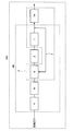
- FIG. 6 is a diagram illustrating an example of a fuel cell system according to the fourth embodiment.
- the fuel cell system 200 includes a reformer 1, a hydrodesulfurizer 2, a recycle channel 3, a booster 4, an ejector 5, a solid oxide fuel cell 7 ⁇ / b> A, A hot module 9.
- the reformer 1, the hydrodesulfurizer 2, the recycle flow path 3, the booster 4 and the ejector 5 are the same as those in the third embodiment, and thus description thereof is omitted.
- the solid oxide fuel cell 7A generates power using the hydrogen-containing gas supplied from the hydrogen generator 100.
- the solid oxide fuel cell 7A uses ion-conducting ceramics as an electrolyte, and oxide ions purified at the air electrode permeate the electrolyte and react with hydrogen at the fuel electrode. Heat is generated.
- the operating temperature of the solid oxide fuel cell 7A is as high as about 700 ° C.-1000 ° C. For this reason, in order to suppress the heat radiation of the high temperature part of the fuel cell system 200 and efficiently use the heat of the high temperature part, it is common to modularize only the high temperature part of the fuel cell system 200 and take a heat insulation configuration. It is.
- the hot module 9 includes the reformer 1 and the solid oxide fuel cell 7A inside as shown in FIG.
- the solid oxide fuel cell 7A and the reformer 1 are an example of a high-temperature portion of the fuel cell system 200, and these are integrated into a module.
- the ejector 5 is configured to receive heat from the hot module 9.
- a hot hot module 9 heats the ejector 5.
- the possibility that the flow path resistance is increased or the flow path is blocked by the condensed water in the ejector 5 can be reduced as compared with the conventional case.
- it replaces with said heater 6A, 6B, and the high temperature hot module 9 may heat the recycling flow path 3.
- FIG. Thereby, the possibility that the flow path resistance is increased due to the condensed water in the recycle flow path 3 or the flow path is blocked can be reduced as compared with the conventional case.
- the recycling flow path 3 and the ejector 5 are arranged inside the hot module 9. Thereby, the recycle flow path 3 and the ejector 5 become easy to receive the heat from the hot module 9.
- the booster 4 has low durability under a high temperature environment, and it is necessary to use expensive heat-resistant parts. Therefore, in the present embodiment, the booster 4 is arranged outside the hot module 9 so that it is difficult to receive heat from the hot module 9.
- FIG. 6 shows an example in which the hydrodesulfurizer 2 is arranged outside the hot module 9, the hydrodesulfurizer 2 may be arranged inside the hot module 9. Thereby, the hydrodesulfurizer 2 can be heated using the hot module 9.
- the operation of the fuel cell system 200 of the present embodiment may be the same as that of the third embodiment. Therefore, detailed description is omitted.
- the fuel cell system according to the fifth embodiment is the same as the fuel cell system according to the fourth embodiment, except that the raw material gas flow path between the booster and the ejector includes an opening / closing valve, and this valve is provided outside the hot module.
- the gas flow between the booster and the ejector can be appropriately blocked using the on-off valve.
- the fuel cell system of the present embodiment may be configured in the same manner as the fuel cell system of the fourth embodiment except for the above features.
- the fuel cell system 200 includes a reformer 1, a hydrodesulfurizer 2, a recycle channel 3, a booster 4, an ejector 5, a solid oxide fuel cell 7 ⁇ / b> A, A hot module 9 and an on-off valve 10 are provided.
- the reformer 1, the hydrodesulfurizer 2, the recycle flow path 3, the booster 4, the ejector 5, the solid oxide fuel cell 7A and the hot module 9 are the same as those in the fourth embodiment, and thus description thereof is omitted. .
- the on-off valve 10 is provided in the raw material gas flow path between the booster 4 and the ejector 5. Thereby, the flow of the gas between both is interrupted.
- the on-off valve 10 may have any configuration as long as it can block the gas flow between the booster 4 and the ejector 5.
- the on-off valve 10 may be, for example, an electromagnetic valve.
- the on-off valve 10 is provided outside the hot module 9.
- the on-off valve 10 is arranged outside the hot module 9 so that the on-off valve 10 is less likely to receive heat from the hot module 9.
- FIG. 7 an example in which the hydrodesulfurizer 2 is disposed outside the hot module 9 is illustrated, but the hydrodesulfurizer 2 may be disposed inside the hot module 9. Thereby, the hydrodesulfurizer 2 can be heated using the hot module 9.
- the on-off valve 10 is opened. Thereby, the source gas can be sent to the ejector 5 by the booster 4.
- the on-off valve 10 When the operation of the fuel cell system 200 is stopped, the on-off valve 10 is closed. Then, since the gas flow between the booster 4 and the ejector 5 is blocked by the on-off valve 10, the supply of the raw material gas from the booster 4 to the ejector 5 is stopped. When the on-off valve 10 remains open, even if the operation of the booster 4 stops, residual gas may flow from the booster 4 to the ejector 5 for a while. Therefore, such a possibility can be reduced by closing the on-off valve 10.
- the gas flow between the booster 4 and the ejector 5 is blocked by the on-off valve 10, the backflow of the gas in the hot module 9 to the booster 4 can be suppressed.
- the gas in the hot module 9 may flow backward to the booster 4 due to the increase in internal pressure of these devices.
- the gas in the hot module 9 include raw material gas, recycle gas, hydrogen-containing gas before flowing into the solid oxide fuel cell 7A, and hydrogen-containing gas (off gas) flowing out from the solid oxide fuel cell 7A.
- the booster 4 may break down, and there is a possibility that flow path resistance increases due to condensed water in the booster 4 or the flow path is blocked. . Therefore, such a possibility can be reduced by closing the on-off valve 10.
- the opening / closing timing of the opening / closing valve 10 may be linked to the opening / closing timing and the gas supply operation timing of the booster 4.
- the on-off valve 10 may be opened almost at the same time as the operation start timing by the booster 4 or at an earlier timing, or at the same time as the operation stop timing by the booster 4 or at a timing later than that.
- the on-off valve 10 may be closed.
- the operation of the fuel cell system 200 of the present embodiment may be the same as that of the fourth embodiment except for the above.
- one embodiment of the present invention can be used in, for example, a hydrogen generator, a fuel cell system, and the like.
Landscapes
- Chemical & Material Sciences (AREA)
- Chemical Kinetics & Catalysis (AREA)
- Engineering & Computer Science (AREA)
- Manufacturing & Machinery (AREA)
- Organic Chemistry (AREA)
- General Chemical & Material Sciences (AREA)
- Sustainable Energy (AREA)
- Electrochemistry (AREA)
- Life Sciences & Earth Sciences (AREA)
- Sustainable Development (AREA)
- Health & Medical Sciences (AREA)
- General Health & Medical Sciences (AREA)
- Combustion & Propulsion (AREA)
- Inorganic Chemistry (AREA)
- Fuel Cell (AREA)
- Hydrogen, Water And Hydrids (AREA)
Abstract
Description
本発明者らは、リサイクル流路からの水素含有ガスが流入するエジェクターでの凝縮水の問題について鋭意検討し、以下の知見を得た。
図1は、第1実施形態の水素生成装置の一例を示す図である。
以下、水素生成装置100の動作について図1を用いて説明する。
本発明者らは、改質器に原料ガスを供給する昇圧器での凝縮水の問題について鋭意検討し、以下の知見を得た。
図2は、第2実施形態の燃料電池システムの一例を示す図である。
第2実施形態の第1変形例の水素生成装置は、第2実施形態の水素生成装置において、上記の加熱器は、リサイクル流路を加熱する。
図3は、第2実施形態の第1変形例の水素生成装置の一例を示す図である。
第2実施形態の第2変形例の水素生成装置は、第2実施形態及び第2実施形態の第1変形例のいずれかの水素生成装置において、加熱器は、改質器を加熱する。
図4は、第2実施形態の第2変形例の水素生成装置の一例を示す図である。
第3実施形態の燃料電池システムは、第2実施形態、第2実施形態の第1変形例及び第2変形例のいずれかの水素生成装置と、この水素生成装置より供給される水素含有ガスを用いて発電する燃料電池とを備える。
図5は、第3実施形態の燃料電池システムの一例を示す図である。
第4実施形態の燃料電池システムは、第3実施形態の燃料電池システムにおいて、燃料電池が固体酸化物形燃料電池であり、改質器と燃料電池とを内部に備えるホットモジュールを備え、エジェクターは、ホットモジュールからの熱を受けるよう構成されている。
図6は、第4実施形態の燃料電池システムの一例を示す図である。
第5実施形態の燃料電池システムは、第4実施形態の燃料電池システムにおいて、昇圧器と、エジェクターとの間の原料ガス流路に開閉弁を備え、この弁はホットモジュール外に設けられる。
図7に示す例では、燃料電池システム200は、改質器1と、水添脱硫器2と、リサイクル流路3と、昇圧器4と、エジェクター5と、固体酸化物形燃料電池7Aと、ホットモジュール9と、開閉弁10と、を備える。
以下、燃料電池システム200の動作について図7を用いて説明する。
2 水添脱硫器
3 リサイクル流路
4 昇圧器
5 エジェクター
6、6A、6B 加熱器
7 燃料電池
7A 固体酸化物形燃料電池
9 ホットモジュール
10 開閉弁
100 水素生成装置
200 燃料電池システム
Claims (7)
- 原料ガスを用いて水素含有ガスを生成する改質器と、前記原料ガス中の硫黄化合物を除去する水添脱硫器と、前記水添脱硫器に流入する前の原料ガスに水素含有ガスを供給するためのリサイクル流路と、前記水添脱硫器よりも上流の原料ガス流路に設けられ、前記リサイクル流路からの水素含有ガスが流入するエジェクターと、前記エジェクターを加熱する加熱器とを備える水素生成装置。
- 前記改質器に原料ガスを供給する昇圧器を備え、
前記エジェクターは、前記昇圧器よりも下流の原料ガス流路に設けられている、請求項1記載の水素生成装置。 - 前記加熱器は、前記リサイクル流路を加熱する、請求項2記載の水素生成装置。
- 前記加熱器は、前記改質器を加熱する、請求項2又は3記載の水素生成装置。
- 請求項2-4のいずれかに記載の水素生成装置と、前記水素生成装置より供給される水素含有ガスを用いて発電する燃料電池とを備える燃料電池システム。
- 前記燃料電池が固体酸化物形燃料電池であり、前記改質器と前記燃料電池とを内部に備えるホットモジュールを備え、前記エジェクターは、前記ホットモジュールからの熱を受けるよう構成されている、請求項5記載の燃料電池システム。
- 前記昇圧器と、前記エジェクターとの間の原料ガス流路に開閉弁を備え、前記弁はホットモジュール外に設けられる、請求項6記載の燃料電池システム。
Priority Applications (3)
| Application Number | Priority Date | Filing Date | Title |
|---|---|---|---|
| US14/648,237 US9472823B2 (en) | 2012-12-27 | 2013-10-16 | Hydrogen generator and fuel cell system |
| JP2014554074A JP6089325B2 (ja) | 2012-12-27 | 2013-10-16 | 水素生成装置及び燃料電池システム |
| EP13867440.3A EP2939977B1 (en) | 2012-12-27 | 2013-10-16 | Hydrogen generation device and fuel cell system |
Applications Claiming Priority (2)
| Application Number | Priority Date | Filing Date | Title |
|---|---|---|---|
| JP2012-285666 | 2012-12-27 | ||
| JP2012285666 | 2012-12-27 |
Publications (1)
| Publication Number | Publication Date |
|---|---|
| WO2014103111A1 true WO2014103111A1 (ja) | 2014-07-03 |
Family
ID=51020251
Family Applications (2)
| Application Number | Title | Priority Date | Filing Date |
|---|---|---|---|
| PCT/JP2013/006014 Ceased WO2014103109A1 (ja) | 2012-12-27 | 2013-10-09 | 水素生成装置及び燃料電池システム |
| PCT/JP2013/006144 Ceased WO2014103111A1 (ja) | 2012-12-27 | 2013-10-16 | 水素生成装置及び燃料電池システム |
Family Applications Before (1)
| Application Number | Title | Priority Date | Filing Date |
|---|---|---|---|
| PCT/JP2013/006014 Ceased WO2014103109A1 (ja) | 2012-12-27 | 2013-10-09 | 水素生成装置及び燃料電池システム |
Country Status (4)
| Country | Link |
|---|---|
| US (2) | US9312555B2 (ja) |
| EP (2) | EP2813466B1 (ja) |
| JP (2) | JP5589155B1 (ja) |
| WO (2) | WO2014103109A1 (ja) |
Families Citing this family (6)
| Publication number | Priority date | Publication date | Assignee | Title |
|---|---|---|---|---|
| JPWO2016021182A1 (ja) * | 2014-08-04 | 2017-05-25 | パナソニックIpマネジメント株式会社 | 水素生成装置およびその運転方法ならびに燃料電池システム |
| JP6348413B2 (ja) * | 2014-12-19 | 2018-06-27 | アイシン精機株式会社 | 燃料電池システム |
| KR102153760B1 (ko) * | 2015-12-31 | 2020-09-09 | 한국조선해양 주식회사 | 선박 |
| CN109244512B (zh) * | 2018-11-06 | 2024-04-12 | 广东索特能源科技有限公司 | 一种带有增压功能的固体氧化物燃料电池发电系统 |
| IT201900008277A1 (it) * | 2019-06-06 | 2020-12-06 | Amec Foster Wheeler Italiana S R L | Processo di produzione di idrogeno |
| KR102555530B1 (ko) * | 2021-05-12 | 2023-07-13 | 한국기계연구원 | 열분해 반응기, 이를 포함하는 수소 생산 시스템, 및 이를 이용한 수소 생산 방법 |
Citations (4)
| Publication number | Priority date | Publication date | Assignee | Title |
|---|---|---|---|---|
| JPH07215701A (ja) * | 1994-01-28 | 1995-08-15 | Tokyo Gas Co Ltd | 炭化水素の水蒸気改質法 |
| JP2006104003A (ja) * | 2004-10-04 | 2006-04-20 | Fuji Electric Holdings Co Ltd | 燃料改質システム |
| JP2008287959A (ja) * | 2007-05-16 | 2008-11-27 | Nippon Oil Corp | 間接内部改質型高温型燃料電池 |
| JP2011216308A (ja) | 2010-03-31 | 2011-10-27 | Osaka Gas Co Ltd | 固体酸化物形燃料電池システム |
Family Cites Families (20)
| Publication number | Priority date | Publication date | Assignee | Title |
|---|---|---|---|---|
| US3655448A (en) | 1969-05-22 | 1972-04-11 | United Aircraft Corp | Hydrogen generator desulfurizer employing feedback ejector |
| JPH05114414A (ja) * | 1991-10-21 | 1993-05-07 | Mitsubishi Electric Corp | 燃料電池発電装置 |
| JPH11214024A (ja) * | 1998-01-26 | 1999-08-06 | Mitsubishi Electric Corp | りん酸型燃料電池発電設備 |
| EP1002779A1 (en) * | 1998-11-18 | 2000-05-24 | Haldor Topsoe A/S | Process for desulphurisation of a hydrocarbon stream |
| US6726836B1 (en) | 2000-09-01 | 2004-04-27 | Utc Fuel Cells, Llc | Method for desulfurizing gasoline or diesel fuel for use in a fuel cell power plant |
| JP4493257B2 (ja) | 2001-03-26 | 2010-06-30 | 大阪瓦斯株式会社 | 燃料改質システム |
| JP3588776B2 (ja) * | 2001-11-09 | 2004-11-17 | 本田技研工業株式会社 | 燃料循環式燃料電池システム |
| JP4911927B2 (ja) | 2004-07-12 | 2012-04-04 | 大阪瓦斯株式会社 | 固体酸化物形燃料電池システム |
| JP2009249203A (ja) | 2008-04-02 | 2009-10-29 | Tokyo Gas Co Ltd | 燃料電池の燃料水素製造用原燃料の脱硫システム |
| JP2009256120A (ja) | 2008-04-14 | 2009-11-05 | T Rad Co Ltd | 改質装置 |
| WO2010044772A1 (en) | 2008-10-14 | 2010-04-22 | Utc Power Corporation | Solid oxide fuel cell with anode exhaust recycle |
| CN102395523B (zh) * | 2009-12-25 | 2015-04-22 | 松下电器产业株式会社 | 氢生成装置和燃料电池系统 |
| JP5636001B2 (ja) | 2009-12-25 | 2014-12-03 | パナソニック株式会社 | 水素生成装置、燃料電池システム、及び水素生成装置の運転方法 |
| JP5647909B2 (ja) * | 2011-01-31 | 2015-01-07 | パナソニックIpマネジメント株式会社 | 水素生成装置および燃料電池システムの運転方法 |
| JP2012171850A (ja) | 2011-02-24 | 2012-09-10 | Panasonic Corp | 水素生成装置、それを備える燃料電池システム、及び水素生成装置の製造方法 |
| JP5214076B1 (ja) | 2011-04-26 | 2013-06-19 | パナソニック株式会社 | 水素生成装置および燃料電池システム |
| JP5501528B2 (ja) * | 2011-05-27 | 2014-05-21 | パナソニック株式会社 | 水素生成装置及びその運転方法並びに燃料電池システム |
| JP2012250876A (ja) * | 2011-06-03 | 2012-12-20 | Panasonic Corp | 水素生成装置及び燃料電池システム |
| JP5681211B2 (ja) | 2011-06-08 | 2015-03-04 | パナソニックIpマネジメント株式会社 | 水素発生装置、これを備える燃料電池システム、及び水素発生装置の運転方法 |
| JP2013222573A (ja) | 2012-04-16 | 2013-10-28 | Panasonic Corp | 燃料電池システム及び水素生成装置 |
-
2013
- 2013-10-09 US US14/378,602 patent/US9312555B2/en not_active Expired - Fee Related
- 2013-10-09 EP EP13867894.1A patent/EP2813466B1/en not_active Not-in-force
- 2013-10-09 JP JP2014514981A patent/JP5589155B1/ja not_active Expired - Fee Related
- 2013-10-09 WO PCT/JP2013/006014 patent/WO2014103109A1/ja not_active Ceased
- 2013-10-16 WO PCT/JP2013/006144 patent/WO2014103111A1/ja not_active Ceased
- 2013-10-16 JP JP2014554074A patent/JP6089325B2/ja not_active Expired - Fee Related
- 2013-10-16 US US14/648,237 patent/US9472823B2/en not_active Expired - Fee Related
- 2013-10-16 EP EP13867440.3A patent/EP2939977B1/en not_active Not-in-force
Patent Citations (4)
| Publication number | Priority date | Publication date | Assignee | Title |
|---|---|---|---|---|
| JPH07215701A (ja) * | 1994-01-28 | 1995-08-15 | Tokyo Gas Co Ltd | 炭化水素の水蒸気改質法 |
| JP2006104003A (ja) * | 2004-10-04 | 2006-04-20 | Fuji Electric Holdings Co Ltd | 燃料改質システム |
| JP2008287959A (ja) * | 2007-05-16 | 2008-11-27 | Nippon Oil Corp | 間接内部改質型高温型燃料電池 |
| JP2011216308A (ja) | 2010-03-31 | 2011-10-27 | Osaka Gas Co Ltd | 固体酸化物形燃料電池システム |
Also Published As
| Publication number | Publication date |
|---|---|
| JP6089325B2 (ja) | 2017-03-08 |
| EP2813466A4 (en) | 2015-04-22 |
| EP2939977A1 (en) | 2015-11-04 |
| US20140377672A1 (en) | 2014-12-25 |
| US9472823B2 (en) | 2016-10-18 |
| JP5589155B1 (ja) | 2014-09-17 |
| EP2813466A1 (en) | 2014-12-17 |
| EP2939977A4 (en) | 2015-12-23 |
| JPWO2014103111A1 (ja) | 2017-01-12 |
| EP2813466B1 (en) | 2016-07-20 |
| US9312555B2 (en) | 2016-04-12 |
| US20150311550A1 (en) | 2015-10-29 |
| WO2014103109A1 (ja) | 2014-07-03 |
| EP2939977B1 (en) | 2019-06-05 |
| JPWO2014103109A1 (ja) | 2017-01-12 |
Similar Documents
| Publication | Publication Date | Title |
|---|---|---|
| JP6089325B2 (ja) | 水素生成装置及び燃料電池システム | |
| EP2361877A1 (en) | Hydrogen generator, fuel cell system, and method of operating hydrogen generator | |
| JP6098795B2 (ja) | 固体酸化物形燃料電池システム | |
| US9527055B2 (en) | Hydrogen generator and fuel cell system | |
| JP6527719B2 (ja) | 燃料電池システム | |
| JP5777433B2 (ja) | 燃料電池発電システムおよびその製造方法 | |
| JP2015135808A (ja) | 燃料電池システム | |
| JP6677458B2 (ja) | 直列燃料電池を利用した発電のシステムおよび方法 | |
| EP2928001B1 (en) | Fuel cell system | |
| CN101127405A (zh) | 具有一氧化碳去除单元的燃料处理器及其运行方法 | |
| JP2011256059A (ja) | 水素生成装置および燃料電池システムの運転方法 | |
| JP5625441B2 (ja) | 燃料電池システム | |
| JP2014135149A (ja) | 燃料電池システム | |
| JP2015185507A (ja) | 燃料電池 | |
| EP2789582B1 (en) | Method of operation of a hydrogen generation apparatus | |
| JP2014107186A (ja) | 固体酸化物形燃料電池システム | |
| JP2014070013A (ja) | 水素生成装置及び燃料電池システム | |
| JP2016100183A (ja) | 燃料電池システム | |
| KR101270790B1 (ko) | 전처리 어셈블리와 이를 포함하는 연료전지 시스템 | |
| JP2014086337A (ja) | 固体酸化物形燃料電池システム |
Legal Events
| Date | Code | Title | Description |
|---|---|---|---|
| 121 | Ep: the epo has been informed by wipo that ep was designated in this application |
Ref document number: 13867440 Country of ref document: EP Kind code of ref document: A1 |
|
| ENP | Entry into the national phase |
Ref document number: 2014554074 Country of ref document: JP Kind code of ref document: A |
|
| WWE | Wipo information: entry into national phase |
Ref document number: 14648237 Country of ref document: US Ref document number: 2013867440 Country of ref document: EP |
|
| NENP | Non-entry into the national phase |
Ref country code: DE |