WO2014103216A1 - 除湿システム - Google Patents
除湿システム Download PDFInfo
- Publication number
- WO2014103216A1 WO2014103216A1 PCT/JP2013/007301 JP2013007301W WO2014103216A1 WO 2014103216 A1 WO2014103216 A1 WO 2014103216A1 JP 2013007301 W JP2013007301 W JP 2013007301W WO 2014103216 A1 WO2014103216 A1 WO 2014103216A1
- Authority
- WO
- WIPO (PCT)
- Prior art keywords
- air
- unit
- adsorption
- dry
- clean room
- Prior art date
- Legal status (The legal status is an assumption and is not a legal conclusion. Google has not performed a legal analysis and makes no representation as to the accuracy of the status listed.)
- Ceased
Links
Images







Classifications
-
- F—MECHANICAL ENGINEERING; LIGHTING; HEATING; WEAPONS; BLASTING
- F24—HEATING; RANGES; VENTILATING
- F24F—AIR-CONDITIONING; AIR-HUMIDIFICATION; VENTILATION; USE OF AIR CURRENTS FOR SCREENING
- F24F3/00—Air-conditioning systems in which conditioned primary air is supplied from one or more central stations to distributing units in the rooms or spaces where it may receive secondary treatment; Apparatus specially designed for such systems
- F24F3/12—Air-conditioning systems in which conditioned primary air is supplied from one or more central stations to distributing units in the rooms or spaces where it may receive secondary treatment; Apparatus specially designed for such systems characterised by the treatment of the air otherwise than by heating and cooling
- F24F3/14—Air-conditioning systems in which conditioned primary air is supplied from one or more central stations to distributing units in the rooms or spaces where it may receive secondary treatment; Apparatus specially designed for such systems characterised by the treatment of the air otherwise than by heating and cooling by humidification; by dehumidification
- F24F3/1411—Air-conditioning systems in which conditioned primary air is supplied from one or more central stations to distributing units in the rooms or spaces where it may receive secondary treatment; Apparatus specially designed for such systems characterised by the treatment of the air otherwise than by heating and cooling by humidification; by dehumidification by absorbing or adsorbing water, e.g. using an hygroscopic desiccant
- F24F3/1429—Air-conditioning systems in which conditioned primary air is supplied from one or more central stations to distributing units in the rooms or spaces where it may receive secondary treatment; Apparatus specially designed for such systems characterised by the treatment of the air otherwise than by heating and cooling by humidification; by dehumidification by absorbing or adsorbing water, e.g. using an hygroscopic desiccant alternatively operating a heat exchanger in an absorbing/adsorbing mode and a heat exchanger in a regeneration mode
-
- F—MECHANICAL ENGINEERING; LIGHTING; HEATING; WEAPONS; BLASTING
- F24—HEATING; RANGES; VENTILATING
- F24F—AIR-CONDITIONING; AIR-HUMIDIFICATION; VENTILATION; USE OF AIR CURRENTS FOR SCREENING
- F24F3/00—Air-conditioning systems in which conditioned primary air is supplied from one or more central stations to distributing units in the rooms or spaces where it may receive secondary treatment; Apparatus specially designed for such systems
- F24F3/12—Air-conditioning systems in which conditioned primary air is supplied from one or more central stations to distributing units in the rooms or spaces where it may receive secondary treatment; Apparatus specially designed for such systems characterised by the treatment of the air otherwise than by heating and cooling
- F24F3/14—Air-conditioning systems in which conditioned primary air is supplied from one or more central stations to distributing units in the rooms or spaces where it may receive secondary treatment; Apparatus specially designed for such systems characterised by the treatment of the air otherwise than by heating and cooling by humidification; by dehumidification
-
- B—PERFORMING OPERATIONS; TRANSPORTING
- B01—PHYSICAL OR CHEMICAL PROCESSES OR APPARATUS IN GENERAL
- B01D—SEPARATION
- B01D53/00—Separation of gases or vapours; Recovering vapours of volatile solvents from gases; Chemical or biological purification of waste gases, e.g. engine exhaust gases, smoke, fumes, flue gases, aerosols
- B01D53/02—Separation of gases or vapours; Recovering vapours of volatile solvents from gases; Chemical or biological purification of waste gases, e.g. engine exhaust gases, smoke, fumes, flue gases, aerosols by adsorption, e.g. preparative gas chromatography
- B01D53/04—Separation of gases or vapours; Recovering vapours of volatile solvents from gases; Chemical or biological purification of waste gases, e.g. engine exhaust gases, smoke, fumes, flue gases, aerosols by adsorption, e.g. preparative gas chromatography with stationary adsorbents
- B01D53/0462—Temperature swing adsorption
-
- B—PERFORMING OPERATIONS; TRANSPORTING
- B01—PHYSICAL OR CHEMICAL PROCESSES OR APPARATUS IN GENERAL
- B01D—SEPARATION
- B01D53/00—Separation of gases or vapours; Recovering vapours of volatile solvents from gases; Chemical or biological purification of waste gases, e.g. engine exhaust gases, smoke, fumes, flue gases, aerosols
- B01D53/02—Separation of gases or vapours; Recovering vapours of volatile solvents from gases; Chemical or biological purification of waste gases, e.g. engine exhaust gases, smoke, fumes, flue gases, aerosols by adsorption, e.g. preparative gas chromatography
- B01D53/06—Separation of gases or vapours; Recovering vapours of volatile solvents from gases; Chemical or biological purification of waste gases, e.g. engine exhaust gases, smoke, fumes, flue gases, aerosols by adsorption, e.g. preparative gas chromatography with moving adsorbents, e.g. rotating beds
-
- B—PERFORMING OPERATIONS; TRANSPORTING
- B01—PHYSICAL OR CHEMICAL PROCESSES OR APPARATUS IN GENERAL
- B01D—SEPARATION
- B01D53/00—Separation of gases or vapours; Recovering vapours of volatile solvents from gases; Chemical or biological purification of waste gases, e.g. engine exhaust gases, smoke, fumes, flue gases, aerosols
- B01D53/26—Drying gases or vapours
- B01D53/261—Drying gases or vapours by adsorption
-
- F—MECHANICAL ENGINEERING; LIGHTING; HEATING; WEAPONS; BLASTING
- F24—HEATING; RANGES; VENTILATING
- F24F—AIR-CONDITIONING; AIR-HUMIDIFICATION; VENTILATION; USE OF AIR CURRENTS FOR SCREENING
- F24F3/00—Air-conditioning systems in which conditioned primary air is supplied from one or more central stations to distributing units in the rooms or spaces where it may receive secondary treatment; Apparatus specially designed for such systems
- F24F3/12—Air-conditioning systems in which conditioned primary air is supplied from one or more central stations to distributing units in the rooms or spaces where it may receive secondary treatment; Apparatus specially designed for such systems characterised by the treatment of the air otherwise than by heating and cooling
- F24F3/16—Air-conditioning systems in which conditioned primary air is supplied from one or more central stations to distributing units in the rooms or spaces where it may receive secondary treatment; Apparatus specially designed for such systems characterised by the treatment of the air otherwise than by heating and cooling by purification, e.g. by filtering; by sterilisation; by ozonisation
- F24F3/167—Clean rooms, i.e. enclosed spaces in which a uniform flow of filtered air is distributed
-
- B—PERFORMING OPERATIONS; TRANSPORTING
- B01—PHYSICAL OR CHEMICAL PROCESSES OR APPARATUS IN GENERAL
- B01D—SEPARATION
- B01D2257/00—Components to be removed
- B01D2257/80—Water
-
- B—PERFORMING OPERATIONS; TRANSPORTING
- B01—PHYSICAL OR CHEMICAL PROCESSES OR APPARATUS IN GENERAL
- B01D—SEPARATION
- B01D2258/00—Sources of waste gases
- B01D2258/06—Polluted air
-
- F—MECHANICAL ENGINEERING; LIGHTING; HEATING; WEAPONS; BLASTING
- F24—HEATING; RANGES; VENTILATING
- F24F—AIR-CONDITIONING; AIR-HUMIDIFICATION; VENTILATION; USE OF AIR CURRENTS FOR SCREENING
- F24F3/00—Air-conditioning systems in which conditioned primary air is supplied from one or more central stations to distributing units in the rooms or spaces where it may receive secondary treatment; Apparatus specially designed for such systems
- F24F3/12—Air-conditioning systems in which conditioned primary air is supplied from one or more central stations to distributing units in the rooms or spaces where it may receive secondary treatment; Apparatus specially designed for such systems characterised by the treatment of the air otherwise than by heating and cooling
- F24F3/14—Air-conditioning systems in which conditioned primary air is supplied from one or more central stations to distributing units in the rooms or spaces where it may receive secondary treatment; Apparatus specially designed for such systems characterised by the treatment of the air otherwise than by heating and cooling by humidification; by dehumidification
- F24F2003/144—Air-conditioning systems in which conditioned primary air is supplied from one or more central stations to distributing units in the rooms or spaces where it may receive secondary treatment; Apparatus specially designed for such systems characterised by the treatment of the air otherwise than by heating and cooling by humidification; by dehumidification by dehumidification only
-
- F—MECHANICAL ENGINEERING; LIGHTING; HEATING; WEAPONS; BLASTING
- F24—HEATING; RANGES; VENTILATING
- F24F—AIR-CONDITIONING; AIR-HUMIDIFICATION; VENTILATION; USE OF AIR CURRENTS FOR SCREENING
- F24F3/00—Air-conditioning systems in which conditioned primary air is supplied from one or more central stations to distributing units in the rooms or spaces where it may receive secondary treatment; Apparatus specially designed for such systems
- F24F3/12—Air-conditioning systems in which conditioned primary air is supplied from one or more central stations to distributing units in the rooms or spaces where it may receive secondary treatment; Apparatus specially designed for such systems characterised by the treatment of the air otherwise than by heating and cooling
- F24F3/14—Air-conditioning systems in which conditioned primary air is supplied from one or more central stations to distributing units in the rooms or spaces where it may receive secondary treatment; Apparatus specially designed for such systems characterised by the treatment of the air otherwise than by heating and cooling by humidification; by dehumidification
- F24F2003/1458—Air-conditioning systems in which conditioned primary air is supplied from one or more central stations to distributing units in the rooms or spaces where it may receive secondary treatment; Apparatus specially designed for such systems characterised by the treatment of the air otherwise than by heating and cooling by humidification; by dehumidification using regenerators
- F24F2003/1464—Air-conditioning systems in which conditioned primary air is supplied from one or more central stations to distributing units in the rooms or spaces where it may receive secondary treatment; Apparatus specially designed for such systems characterised by the treatment of the air otherwise than by heating and cooling by humidification; by dehumidification using regenerators using rotating regenerators
-
- Y—GENERAL TAGGING OF NEW TECHNOLOGICAL DEVELOPMENTS; GENERAL TAGGING OF CROSS-SECTIONAL TECHNOLOGIES SPANNING OVER SEVERAL SECTIONS OF THE IPC; TECHNICAL SUBJECTS COVERED BY FORMER USPC CROSS-REFERENCE ART COLLECTIONS [XRACs] AND DIGESTS
- Y02—TECHNOLOGIES OR APPLICATIONS FOR MITIGATION OR ADAPTATION AGAINST CLIMATE CHANGE
- Y02P—CLIMATE CHANGE MITIGATION TECHNOLOGIES IN THE PRODUCTION OR PROCESSING OF GOODS
- Y02P70/00—Climate change mitigation technologies in the production process for final industrial or consumer products
- Y02P70/50—Manufacturing or production processes characterised by the final manufactured product
Definitions
- the present invention relates to a dehumidification system that supplies dehumidified air into a room.
- Patent Documents 1 and 2 disclose this type of dehumidification system.
- Patent Documents 1 and 2 describe a configuration in which adsorption rotors are arranged in a plurality of stages in series on an air passage.
- the air passage is composed of an air supply passage that supplies outdoor air after processing it with an adsorption rotor, and an exhaust passage that discharges indoor air to the outside.
- the adsorption rotor is disposed across the air supply passage and the exhaust passage, and is configured to be rotatable about a rotation axis between both passages.
- the adsorption rotor adsorbs moisture in the air flowing through the air supply passage to dehumidify it, and regenerates it by releasing moisture into the air flowing through the exhaust passage.
- the exhaust passage is provided with a heater for heating air in order to heat the air and use it for regeneration of the adsorption rotor.
- the adsorption rotor rotates and moves to the exhaust passage when the moisture adsorption amount of the portion that adsorbs moisture increases, and is regenerated by releasing moisture therein, and then used again on the adsorption side.
- the air adsorbed into the room becomes air with a low dew point.
- the air supplied to a dry clean room for manufacturing a lithium ion battery (air with a dew point of about ⁇ 50 ° C.) Can be used.
- each adsorption rotor becomes a dehumidification regeneration unit.
- the adsorption rotor itself is a high-cost component. Since the regeneration temperature of the adsorption rotor by the heater is high, the running cost required for the heat quantity of the heater is also increased.
- the energy consumption of the air conditioning system accounts for about 50%, and energy saving of this system greatly contributes to the cost reduction of the lithium battery.
- the amount of heat provided for the regeneration of the adsorption rotor is large, it has been extremely difficult to realize a reduction in cost of the dehumidification system.
- the present invention has been made in view of such points, and an object thereof is to enable energy saving and cost reduction of the dehumidification system.
- 1st invention presupposes the dehumidification system provided with the dehumidification apparatus (40, 50) which supplies dehumidified air to a dry clean room (S1).
- the dehumidification system includes a dry chamber (S2) to which air having a lower humidity than that of the dry clean room (S1) is supplied, and the dehumidifier (40, 50) supplies air to the dry clean room (S1).
- a main dehumidifying unit (40) provided in the air supply passage (20) and a terminal dehumidifying unit (50) for processing air supplied to the dry chamber (S2) are provided.
- Dehumidifying unit (50) which is switched to the first and second regenerating parts, and the terminal dehumidifying unit (50) dehumidifies the air in the dry clean room (S1) and supplies it to the dry chamber (S2) And a second adsorbing member (51, 52) that is switched to a regenerating unit that is regenerated with air in a dry clean room (S1).
- the entire dry clean room (S1) has been dehumidified so that the dew point temperature becomes, for example, ⁇ 50 ° C., but in the first invention, the environment of a low dew point temperature such as ⁇ 50 ° C. is used.
- a dry chamber (S2) in the area where the air is actually needed, if only the dry chamber (S2) has a low dew point of -50 ° C, the air supplied to the dry clean room (S1) will have a dew point temperature higher than that. Can be high.
- the air in the dry clean room (S1) supplied from the main dehumidifying unit (40) can be further processed by the terminal dehumidifying unit (50) and supplied to the dry chamber (S2).
- the air in the dry clean room (S1) is also used as air for regenerating the regeneration unit of the terminal dehumidifying unit (50).
- the second invention is characterized in that, in the first invention, the dry chamber (S2) is provided in a dry clean room (S1).
- the air in the dry clean room (S1) supplied from the main dehumidifying unit (40) is further processed by the terminal dehumidifying unit (50) to obtain low dew point temperature air, and the dry clean room (S1) It can be supplied to the internal dry chamber (S2).
- the third invention is characterized in that, in the first invention, the dry chamber (S2) is provided outside the dry clean room (S1).
- the air in the dry clean room (S1) supplied from the main dehumidifying unit (40) is further processed by the terminal dehumidifying unit (50) to obtain low dew point temperature air, and the dry clean room (S1) Can be supplied to an external dry chamber (S2).
- the regeneration passage (32) supplies the air flowing out from the regeneration section of the terminal dehumidification unit (50) to the regeneration section of the main dehumidification unit (40). ).
- the main dehumidification unit (40) is regenerated by the air regenerated from the terminal dehumidification unit (50).
- the main dehumidifying unit (40) includes a switching dehumidifying unit (41) and a rotor dehumidifying unit (42), and the switching dehumidifying unit.
- the unit (41) includes two adsorption heat exchangers (43, 44) that are alternately switched between the adsorption side and the regeneration side as the first adsorption member (43, 44), and the adsorption heat exchanger on the adsorption side (43, 44), the rotor type dehumidifying unit (42) is partly configured as an adsorbing part and the other part is configured as a regenerating part.
- the terminal dehumidification unit (50) is adsorbed as the second adsorption member (51, 52).
- Adsorption heat exchange that can be switched alternately to the regeneration side and the regeneration side It is characterized in that it is provided with an exchanger (51, 52), and is configured to dehumidify the air in the dry clean room (S1) with the heat exchanger on the adsorption side and supply it to the dry chamber (S2).
- the air dehumidified by the switching dehumidifying unit (41) provided with the adsorption heat exchanger (43, 44) is the rotor type dehumidifying having the adsorption rotor (45). It is supplied to the unit (42) and further dehumidified. Since the dehumidified air that has passed through the adsorption heat exchanger (43, 44) has low humidity and low temperature, generation of adsorption heat in the adsorption rotor (45) can be suppressed.
- the terminal dehumidification unit (50) is also a switchable dehumidification unit using the adsorption heat exchanger (51, 52), the air in the dry clean room (S1) becomes low-humidity and low-temperature air.
- a plurality of dry chambers (S2) are provided, and a terminal dehumidifying unit (50) is provided for each dry chamber (S2). It is characterized by that.
- low dew point air treated by the terminal dehumidifying unit (50) is supplied to each dry chamber (S2).
- the air in the dry clean room (S1) supplied from the main dehumidifying unit (40) can be further processed by the terminal dehumidifying unit (50) and supplied to the dry chamber (S2).
- the dew point temperature of the air produced by the dehumidifying unit (40) may be higher than the dew point temperature of the air supplied to the dry chamber (S2), and the power consumption required for dehumidification by the main dehumidifying unit (40) can be reduced.
- the dew point temperature of the air generated by the main dehumidifying unit (40) can be raised, the power consumption required for regeneration can be reduced.
- the low dew point air of the dry clean room (S1) is used for the regeneration of the terminal dehumidification unit (50), it can be efficiently regenerated and the regeneration energy can be reduced.
- the air in the dry clean room (S1) is processed by the terminal dehumidification unit (50) and supplied to the dry chamber (S2) provided in the dry clean room (S1). Energy savings can be realized while satisfying the conditions of the dry chamber (S2) that requires dew point air.
- the air in the dry clean room (S1) is processed by the terminal dehumidification unit (50) and supplied to the dry chamber (S2) provided outside the dry clean room (S1). Energy savings can be realized while satisfying the conditions of the dry chamber (S2) that requires dew point air.
- the main dehumidifying unit (40) can be regenerated with this air. And by doing in this way, the heating energy for reproducing
- the air dehumidified by the switching dehumidifying unit (41) including the adsorption heat exchanger (43, 44) has the adsorption rotor (45).
- the dehumidification unit (42) is supplied and further dehumidified.
- the dehumidified air that has passed through the adsorption heat exchanger (43, 44) of the main dehumidification unit (40) is low in humidity and low in temperature, generation of adsorption heat in the adsorption rotor (45) can be suppressed.
- the regeneration energy of the adsorption rotor (45) can be suppressed.
- the terminal dehumidification unit (50) is also a switchable dehumidification unit using adsorption heat exchangers (51, 52), so the air in the dry clean room (S1) becomes low-humidity and low-temperature air, and the terminal dehumidification unit (50) and the main dehumidifying unit (40) are effective in reducing the regenerative energy.
- the terminal dehumidifying unit (50) is provided for each dry chamber (S2), the air having the dew point temperature required for each dry chamber (S2) is supplied to each dry chamber (S2). it can.
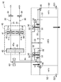
- FIG. 1 is a configuration diagram of a dehumidification system according to an embodiment of the present invention.
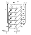
- FIG. 2 is a perspective view showing a schematic configuration of the switchable dehumidifying unit.
- FIG. 3 is a diagram showing the state of air in the dehumidification system of FIG.
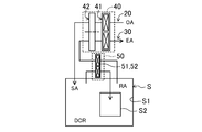
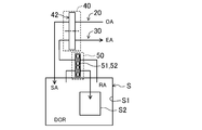
- FIG. 4 is a schematic configuration diagram of the dehumidification system of FIG.
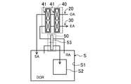
- FIG. 5 is a schematic configuration diagram of a dehumidification system according to the first modification.
- FIG. 6 is a schematic configuration diagram of a dehumidification system according to Modification 2.
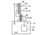
- FIG. 7 is a schematic configuration diagram of a dehumidification system according to Modification 3.
- FIG. 8 is a schematic configuration diagram of a dehumidification system according to Modification 4.
- FIG. 1 is a configuration diagram of a dehumidification system according to an embodiment of the present invention.
- FIG. 2 is a perspective view showing a schematic configuration of the switchable dehumidifying unit.
- FIG. 9 is a schematic configuration diagram of a dehumidification system according to Modification 5.
- FIG. 10 is a schematic configuration diagram of a dehumidification system according to Modification 6.
- FIG. 11 is a schematic configuration diagram of a dehumidification system according to Modification 7.
- FIG. 12 is a system configuration diagram of a dehumidification system according to Modification 8.
- FIG. 13 is a system configuration diagram of a dehumidification system according to Modification 9.
- the embodiment shown in FIG. 1 relates to a dehumidification system (10) that dehumidifies the indoor space (S).
- This dehumidification system (10) dehumidifies outdoor air (OA) and supplies this air to the room as supply air (SA).
- SA supply air
- the indoor space (S) to be dehumidified is a dry clean area of a lithium battery production line where low dew point air is required, and the dehumidification system (10) of FIG. 1 constitutes a part of the lithium ion battery production line. Is.
- the indoor space (S) includes a dry clean room (S1) and a dry chamber (S2).
- the dry chamber (S2) is provided in an area in the dry clean room (S1) where particularly low dew point air (in this embodiment, air having a dew point temperature of ⁇ 50 ° C.) is required.
- air with a dew point temperature of ⁇ 50 ° C is not required in the space inside the dry clean room (S1) except the dry chamber (S2).
- the dry clean room (S1) is provided with a dry chamber (S2) to which air having a dew point lower than that of the dry clean room (S1) is supplied.
- the dry chamber (S2) may be a space that a person can enter, or a relatively small space that allows a person to work without entering a person.
- This dehumidification system (10) includes an air supply passage (20) for dehumidifying outdoor air (OA) and supplying it to the indoor space (S) as supply air (SA).
- the dehumidification system (10) includes an exhaust passage (30) that discharges the indoor air (RA) of the dry clean room (S1) to the outside as exhaust air (EA).
- This dehumidifying system (10) is supplied as a dehumidifying device (40, 50) to the main dehumidifying unit (40) provided in the air supply passage (20) for dehumidifying the outdoor air (OA) and the dry chamber (S2). And a terminal dehumidifying unit (50) for processing air.
- the air supply passage (20) includes a first air supply passage (21) passing through the main dehumidification unit (40) and a second air supply passage (22) passing through the terminal dehumidification unit (50).
- the exhaust passage (30) includes a first exhaust passage (31) passing through the main dehumidification unit (40) and a second exhaust passage (32) passing through the terminal dehumidification unit (50).
- the first air supply passage (21) is a passage for supplying the air treated by the main dehumidification unit (40) to the dry clean room (S1)
- the second air supply passage (22) is the air in the dry clean room (S1). Is a passage that is processed by the terminal dehumidification unit (50) and supplied to the dry chamber (S2).
- the second exhaust passage (32) is a passage through which the air of the dry clean room (S1) passes through the terminal dehumidification unit 50), and the first exhaust passage (31) is the air after passing through the terminal dehumidification unit (50). Is a passage through which the main dehumidifying unit (40) passes and then discharged to the outside.
- the main dehumidifying unit (40) includes a switching dehumidifying unit (41) and a rotor dehumidifying unit (42).
- the switchable dehumidifying unit (41) includes two adsorption heat exchangers (43, 44) that can be switched alternately between the adsorption side and the regeneration side, and dehumidifies the air with the adsorption heat exchanger (43, 44) on the adsorption side. It is configured as follows.
- the adsorption heat exchanger (43, 44) is a heat exchanger in which an adsorbent is supported on the fin surface of the air heat exchanger.
- the switchable dehumidifying unit (41) is configured such that the air flowing through the first air supply passage (21) always passes through the adsorption heat exchanger (43, 44) on the adsorption side, A configuration is adopted in which the flow of air in the casing is switched so that the air flowing through the exhaust passage (31) always passes through the regeneration-side adsorption heat exchanger (44, 43).
- the pair of adsorption heat exchangers (43, 44) is composed of two heat exchangers in the refrigerant circuit, and by reversing the circulation direction of the refrigerant, a heat exchanger that becomes an evaporator and a heat exchanger that becomes a condenser Are switched so that the suction side and the regeneration side are switched alternately.
- FIG. 2 shows a schematic configuration of the switchable dehumidifying unit (41).
- the switchable dehumidifying unit (41) is composed of a plurality of (in this embodiment, five) subunits (46).
- Each of the subunits (46) has a box-shaped casing (46a), and a pair of the adsorption heat exchangers (43, 44) not shown in FIG. 2 is accommodated in each casing (46a). Yes.
- each subunit (46) has a treatment inlet (41a) through which outdoor air flows, a regeneration inlet (41b) through which regeneration air flows, and a treatment outlet (41c) through which process air flows out, A regeneration outlet (41d) through which the exhaust flows is provided.
- the plurality of subunits (46) are connected in parallel to the air supply passage (20) and the exhaust passage (30).
- the outdoor air flowing through the air supply passage (20) branches and flows into each subunit (46) from the processing inlet (41a) and is dehumidified by the adsorption heat exchanger (43, 44) on the adsorption side. After that, it flows out from the processing outlet (41c) and flows downstream.
- the room air flowing through the exhaust passage (30) branches and flows into each subunit (46) from the regeneration inlet (41b), and after regeneration of the regeneration-side adsorption heat exchanger (44, 43), the regeneration outlet. It flows out of (41d) and is discharged outside the room.
- the pair of adsorption heat exchangers (43, 44) are alternately switched between the adsorption side and the regeneration side at a predetermined timing (for example, at intervals of 3 minutes).
- the casing (46a) is configured to switch the air flow in the air passage as the pair of adsorption heat exchangers (43, 44) are switched between the adsorption side and the regeneration side.
- the rotor-type dehumidifying unit (42) includes an adsorption rotor (45) partly configured as an adsorption part and the other part as a regeneration part, and rotates about a rotation shaft (45a). It is configured.
- the adsorption rotor (45) has a structure in which an adsorbent is supported on the surface of a substrate having a honeycomb structure, a portion through which air flowing through the first air supply passage (21) passes is an adsorption portion, and a first exhaust passage ( The part through which the air flowing through 31) passes is the regenerating part.
- the air dehumidified by the adsorption heat exchanger (43, 44) on the adsorption side of the switching dehumidification unit (41) is further dehumidified by the adsorption portion of the adsorption rotor (45).
- Each of the adsorption heat exchangers (43, 44) and the adsorption rotor (45) is a first adsorption member that can be switched between an adsorption unit and a regeneration unit.
- the terminal dehumidifying unit (50) is equipped with two adsorption heat exchangers (51, 52) that can be switched alternately between the adsorption side and the regeneration side, and the air in the dry clean room (S1) is absorbed into the adsorption heat exchanger (51, 52). It is configured to dehumidify and supply to the dry chamber (S2) at 52).
- the adsorption heat exchanger (51, 52) of the terminal dehumidification unit (50) dehumidifies the air in the dry clean room (S1) and supplies it to the dry chamber (S2), and the regeneration regenerated with the air in the dry clean room It is the 2nd adsorption
- a precooling heat exchanger (61) is disposed upstream of the main dehumidifying unit (40) in the first air supply passage (21), and a reheat heat exchanger (62) is disposed downstream of the main dehumidifying unit (40). ) Is arranged. Moreover, the 2nd reheat heat exchanger (63) is arrange
- a plurality of dry chambers (S2) are provided in the dry clean room (S1), and a terminal dehumidifying unit (50) is provided for each dry chamber (S2). Further, a honeycomb-structured moisture absorbent (65) is provided at the air inlet to each dry chamber (S2) on the downstream side of the second reheat heat exchanger (63).
- the dry chamber (S2) is provided with an outflow path (S21) through which the low dew point air of the dry chamber (S2) flows out to the dry clean room (S1).
- the second exhaust passage (32) is a regeneration passage for supplying air flowing out from the adsorption heat exchanger (52, 51) serving as a regeneration portion of the terminal dehumidification unit (50) to the regeneration portion of the main dehumidification unit (40).
- the dry clean room (S1) is provided with a third exhaust passage (33) for discharging the low dew point air of the dry clean room (S1), and the third exhaust passage (33) is connected to the second exhaust passage (33).
- 32) joins downstream of the adsorption heat exchanger (52, 51) of the terminal dehumidification unit (50).
- the precooling heat exchanger (61), the exhaust cooling heat exchanger (64), the reheat heat exchanger (62), and the second reheat heat exchanger (63) are connected to a refrigerant circuit of a heat recovery unit (not shown). It is connected.
- the refrigerant circuit uses the reheat heat exchanger (62) and the second reheat heat exchanger (63) as a condenser, and evaporates the precooling heat exchanger (61) and the exhaust cooling heat exchanger (64).
- the apparatus is configured to perform a refrigeration cycle.
- FIG. 3 is a diagram showing the state of air at points A to O
- FIG. 4 is a simplified diagram of the dehumidification system (10).
- the four columns for each point in Fig. 3 include the air volume (m 3 / min) in the upper left column, the absolute humidity (g / kg) in the lower left column, the dry bulb temperature DB (° C) in the upper right column, and the dew point in the lower right column.
- the temperature DP (° C.) is shown.
- the outdoor air at point A flowing through the air supply passage (20) is cooled and dehumidified by the precooling heat exchanger (61), and then flows into the main dehumidifying unit (40) to be dehumidified.
- This air further changes in the order of B point, C point, D point and E point, becomes air having a dew point temperature of ⁇ 35 ° C., and is supplied to the dry clean room (S1).
- the air at point F in the dry clean room (S1) passes through the terminal dehumidification unit (50), changes its state from point G to point H, the dew point temperature becomes -50 ° C, and is supplied to the dry chamber (S2).
- the air in the dry chamber (S2) is sequentially released to the dry clean room (S1).
- the air at the point J is mixed with the air whose state has changed from the point I to the point K by the terminal dehumidifying unit (50), and the air becomes the state of the point L.
- the air at point L shown in FIG. 3 is an example when three terminal dehumidification units (50) are used.
- the air at point L passes through the main dehumidifying unit (40) and the exhaust cooling heat exchanger, changes its state in the order of point M, point N and point O, and is discharged from the exhaust passage (30) to the outside.
- the air supplied from the main dehumidifying unit (40) to the dry clean room (S1) is further processed by the terminal dehumidifying unit (50) and supplied to the dry chamber (S2). Therefore, since the dew point temperature of the air produced by the main dehumidifying unit (40) may be higher than the dew point temperature of the air supplied to the dry chamber (S2), the power consumption required for dehumidification can be reduced.
- the dew point temperature of the air generated by the main dehumidification unit (40) can be raised above the air dew point temperature required for the dry chamber (S2), the power consumption required for regeneration can be reduced by reducing the amount of moisture for regeneration. it can.
- the main dehumidifying unit (40) since the air regenerated from the terminal dehumidifying unit is low in humidity, the main dehumidifying unit (40) can be regenerated without heating the air at point L.
- the air dehumidified by the switching dehumidifying unit (41) provided with the adsorption heat exchanger (43, 44) is further transferred by the adsorption rotor (45) of the rotor dehumidifying unit (42).
- the dehumidified air that has passed through the adsorption heat exchanger (43, 44) is low in humidity and low in temperature. Therefore, since the generation of heat of adsorption is suppressed in the adsorption rotor (45), the regeneration energy of the adsorption rotor (45) can be suppressed.
- the switching dehumidification unit using the adsorption heat exchanger (51, 52) is used for the terminal dehumidification unit (50)
- the air in the dry clean room (S1) becomes low-humidity and low-temperature air.
- the low dew point air of a dry clean room (S1) is used for reproduction
- regenerate efficiently the regeneration energy of a terminal dehumidification unit (50) can be suppressed.
- the terminal dehumidification unit (50) is provided for each dry chamber (S2), the air at the dew point temperature required for each dry chamber (S2) is reliably supplied to each terminal dehumidification unit (50). Can be generated.
- the hygroscopic material (65) is arrange
- the terminal dehumidifying unit (50) is configured by an adsorption rotor (53) instead of the adsorption heat exchanger (51, 52) in the embodiment of FIG.
- the dew point temperature of the air produced by the main dehumidifying unit (40) is higher than the dew point temperature of the air supplied to the dry chamber (S2). Since it may be high, power consumption required for dehumidification can be suppressed, and power consumption required for regeneration can also be suppressed.
- the main dehumidifying unit (40) is configured by two switchable dehumidifying units (41) in the embodiment of FIG.
- the modification 3 shown in FIG. 7 is an example which comprised the terminal dehumidification unit (50) by the adsorption
- the main dehumidifying unit (40) is configured by one switchable dehumidifying unit (41) in the embodiment of FIG.
- the modification 5 shown in FIG. 9 is an example which comprised the terminal dehumidification unit (50) by the adsorption
- the main dehumidifying unit (40) is constituted by one rotor type dehumidifying unit (42) in the embodiment of FIG.
- the modification 7 shown in FIG. 11 is an example which comprised the terminal dehumidification unit (50) by the adsorption
- FIGS. 1 to 3 show a system configuration in which the dry chamber (S2) is provided inside the dry clean room (S1). As shown in FIGS.
- the dry chamber (S2) may be provided outside the dry clean room (S1).
- Modification 8 shown in FIG. 12 is an example in which a dry chamber (S2) is installed in the vicinity of the dry clean room (S1), and the dry clean room (S1) and the dry chamber (S2) are not adjacent to each other.
- is there. 13 is an example in which a dry chamber (S2) is installed adjacent to the dry clean room (S1), and the dry clean room (S1) and the dry chamber (S2) are adjacent to each other. This is the case.
- air having a dew point temperature of ⁇ 35 ° C. dehumidified by the main dehumidifying unit (40) is supplied to the dry clean room (S1), and the air in the dry clean room (S1) is supplied to the terminal.
- the dehumidification unit (50) further dehumidifies the dew point to ⁇ 50 ° C., and is supplied to the dry chamber (S2) outside the dry clean room (S1) through the second air supply passage (22).
- the other air flows are the same as those in the embodiment shown in FIGS.
- the above embodiment is an essentially preferable example, and is not intended to limit the scope of the present invention, its application, or its use.
- the air state at each point shown in FIG. 3 can be changed according to the dew point temperature of air required in the dry clean room or the dry chamber, the specific configuration of the apparatus, or the like.
- the present invention is useful for a dehumidification system that supplies dehumidified air into a room.
- Dehumidification system 20 Air supply passage 32 Regeneration passage 40 Main dehumidification unit (dehumidification device) 41 Switching dehumidification unit 42 Rotor dehumidification unit 43 Adsorption heat exchanger (first adsorption member) 44 Adsorption heat exchanger (first adsorption member) 45 Suction rotor (first suction member) 50 Terminal dehumidification unit (dehumidifier) 51 Adsorption heat exchanger (second adsorption member) 52 Adsorption heat exchanger (second adsorption member) S1 Dry clean room S2 Dry chamber
Landscapes
- Chemical & Material Sciences (AREA)
- Engineering & Computer Science (AREA)
- Analytical Chemistry (AREA)
- General Chemical & Material Sciences (AREA)
- Oil, Petroleum & Natural Gas (AREA)
- Chemical Kinetics & Catalysis (AREA)
- Combustion & Propulsion (AREA)
- Mechanical Engineering (AREA)
- General Engineering & Computer Science (AREA)
- Drying Of Gases (AREA)
- Central Air Conditioning (AREA)
- Secondary Cells (AREA)
Abstract
Description
次に、この除湿システム(10)の運転動作を説明する。図3は、A点からO点の各点における空気の状態を表した図であり、図4は除湿システム(10)を簡略化した図である。図3の各点の4つの欄には、左上欄に風量(m3/min)、左下欄に絶対湿度(g/kg)、右上欄に乾球温度DB(℃)、右下欄に露点温度DP(℃)を示している。
本実施形態によれば、主除湿ユニット(40)からドライクリーンルーム(S1)に供給された空気を、さらにターミナル除湿ユニット(50)で処理してドライチャンバ(S2)に供給するようにしている。したがって、主除湿ユニット(40)で作る空気の露点温度がドライチャンバ(S2)に供給する空気の露点温度よりも高くてもよくなるので、除湿に要する消費電力を削減できる。
上記実施形態については、以下のような構成としてもよい。
20 給気通路
32 再生通路
40 主除湿ユニット(除湿装置)
41 切り換え式除湿ユニット
42 ロータ式除湿ユニット
43 吸着熱交換器(第1吸着部材)
44 吸着熱交換器(第1吸着部材)
45 吸着ロータ(第1吸着部材)
50 ターミナル除湿ユニット(除湿装置)
51 吸着熱交換器(第2吸着部材)
52 吸着熱交換器(第2吸着部材)
S1 ドライクリーンルーム
S2 ドライチャンバ
Claims (6)
- ドライクリーンルーム(S1)に除湿空気を供給する除湿装置(40,50)を備えた除湿システムであって、
ドライクリーンルーム(S1)よりも低湿度の空気が供給されるドライチャンバ(S2)を備え、
上記除湿装置(40,50)は、ドライクリーンルーム(S1)へ空気を供給する給気通路(20)に設けられた主除湿ユニット(40)と、ドライチャンバ(S2)に供給する空気を処理するターミナル除湿ユニット(50)とを備え、
主除湿ユニット(40)は、吸着部と再生部とに切り換えられる第1吸着部材(43,44)(45)を備え、
ターミナル除湿ユニット(50)は、ドライクリーンルーム(S1)の空気を除湿してドライチャンバ(S2)に供給する除湿部と、ドライクリーンルーム(S1)の空気で再生される再生部とに切り換えられる第2吸着部材(51,52)を備えていることを特徴とする除湿システム。 - 請求項1において、
上記ドライチャンバ(S2)がドライクリーンルーム(S1)の内部に設けられていることを特徴とする除湿システム。 - 請求項1において、
上記ドライチャンバ(S2)がドライクリーンルーム(S1)の外部に設けられていることを特徴とする除湿システム。 - 請求項1から3の何れか1つにおいて、
ターミナル除湿ユニット(50)の再生部から流出した空気を主除湿ユニット(40)の再生部に供給する再生通路(32)を備えていることを特徴とする除湿システム。 - 請求項1から4の何れか1つにおいて、
主除湿ユニット(40)は、切り換え式除湿ユニット(41)とロータ式除湿ユニット(42)とを備え、切り換え式除湿ユニット(41)は、上記第1吸着部材(43,44)として吸着側と再生側に交互に切り換えられる2つの吸着熱交換器(43,44)を備え、空気を吸着側の吸着熱交換器(43,44)で除湿するように構成され、ロータ式除湿ユニット(42)は、一部が吸着部として構成されるとともに他の一部が再生部として構成された上記第1吸着部材(45)としての吸着ロータ(45)を備え、切り換え式除湿ユニット(41)で除湿した空気を除湿するように構成され、
ターミナル除湿ユニット(50)は、上記第2吸着部材(51,52)として吸着側と再生側に交互に切り換えられる2つの吸着熱交換器(51,52)を備え、ドライクリーンルーム(S1)の空気を吸着側の吸着熱交換器(51,52)で除湿してドライチャンバ(S2)に供給するように構成されていることを特徴とする除湿システム。 - 請求項1から5の何れか1つにおいて、
複数のドライチャンバ(S2)が設けられ、
上記ドライチャンバ(S2)ごとにターミナル除湿ユニット(50)が設けられていることを特徴とする除湿システム。
Priority Applications (4)
| Application Number | Priority Date | Filing Date | Title |
|---|---|---|---|
| CN201380066244.3A CN104870907B (zh) | 2012-12-28 | 2013-12-11 | 除湿系统 |
| US14/646,487 US9297543B2 (en) | 2012-12-28 | 2013-12-11 | Dehumidification system |
| BR112015013250A BR112015013250A2 (pt) | 2012-12-28 | 2013-12-11 | sistema de desumidificação |
| EP13866824.9A EP2940393B1 (en) | 2012-12-28 | 2013-12-11 | Dehumidification system |
Applications Claiming Priority (2)
| Application Number | Priority Date | Filing Date | Title |
|---|---|---|---|
| JP2012288274 | 2012-12-28 | ||
| JP2012-288274 | 2012-12-28 |
Publications (1)
| Publication Number | Publication Date |
|---|---|
| WO2014103216A1 true WO2014103216A1 (ja) | 2014-07-03 |
Family
ID=51020340
Family Applications (1)
| Application Number | Title | Priority Date | Filing Date |
|---|---|---|---|
| PCT/JP2013/007301 Ceased WO2014103216A1 (ja) | 2012-12-28 | 2013-12-11 | 除湿システム |
Country Status (7)
| Country | Link |
|---|---|
| US (1) | US9297543B2 (ja) |
| EP (1) | EP2940393B1 (ja) |
| JP (1) | JP5521106B1 (ja) |
| KR (1) | KR101553202B1 (ja) |
| CN (1) | CN104870907B (ja) |
| BR (1) | BR112015013250A2 (ja) |
| WO (1) | WO2014103216A1 (ja) |
Families Citing this family (7)
| Publication number | Priority date | Publication date | Assignee | Title |
|---|---|---|---|---|
| US11091244B2 (en) | 2014-03-06 | 2021-08-17 | Riteaire Marine Llc | Marine vessel dehumidification system |
| US10538302B2 (en) * | 2014-03-06 | 2020-01-21 | Riteaire Marine Llc | Marine vessel dehumidification system |
| JP6342234B2 (ja) | 2014-06-30 | 2018-06-13 | ナブテスコ株式会社 | 除湿装置及び除湿モジュール |
| JP6009531B2 (ja) * | 2014-12-26 | 2016-10-19 | ダイキン工業株式会社 | 除湿システム |
| US11859835B2 (en) * | 2016-06-27 | 2024-01-02 | Daikin Industries, Ltd. | Humidity control apparatus with dual heat exchangers and bypass passage |
| JP6576323B2 (ja) * | 2016-12-14 | 2019-09-18 | 株式会社大気社 | 塗装用乾燥設備 |
| CN115419958A (zh) * | 2022-11-04 | 2022-12-02 | 浙江捷峰环境科技有限公司 | 新风双转轮与全回风单转轮除湿机的组合除湿系统及方法 |
Citations (4)
| Publication number | Priority date | Publication date | Assignee | Title |
|---|---|---|---|---|
| JP2001038137A (ja) * | 1999-07-30 | 2001-02-13 | Takasago Thermal Eng Co Ltd | 清浄空気製造方法及び供給システム |
| JP2002320817A (ja) * | 2001-04-24 | 2002-11-05 | Takasago Thermal Eng Co Ltd | 除湿装置及び除湿方法 |
| JP3762138B2 (ja) | 1999-04-23 | 2006-04-05 | 高砂熱学工業株式会社 | 乾式減湿システム |
| JP2011064439A (ja) | 2009-09-18 | 2011-03-31 | Shinko Kogyo Co Ltd | 超低露点温度の乾燥空気を供給するデシカント空調機 |
Family Cites Families (8)
| Publication number | Priority date | Publication date | Assignee | Title |
|---|---|---|---|---|
| US3619987A (en) * | 1969-11-10 | 1971-11-16 | Oliver D Colvin | Devaporizing systems |
| US6355091B1 (en) | 2000-03-06 | 2002-03-12 | Honeywell International Inc. | Ventilating dehumidifying system using a wheel for both heat recovery and dehumidification |
| JP3676983B2 (ja) * | 2000-03-29 | 2005-07-27 | 株式会社日立国際電気 | 半導体製造方法、基板処理方法、及び半導体製造装置 |
| US6772534B2 (en) * | 2002-03-15 | 2004-08-10 | Bel-Art Products, Inc. | Apparatus and method for moisture control |
| JP3482409B1 (ja) * | 2002-05-30 | 2003-12-22 | 東京エレクトロン株式会社 | 減湿装置及び減湿方法 |
| JP4468021B2 (ja) * | 2003-03-25 | 2010-05-26 | キヤノン株式会社 | ロードロックシステム及び露光処理システム並びにデバイスの製造方法 |
| JP4432369B2 (ja) * | 2003-05-30 | 2010-03-17 | ダイキン工業株式会社 | 調湿装置 |
| JP4775623B2 (ja) * | 2004-10-26 | 2011-09-21 | 株式会社日立プラントテクノロジー | 除湿システム |
-
2013
- 2013-12-11 KR KR1020157018035A patent/KR101553202B1/ko active Active
- 2013-12-11 US US14/646,487 patent/US9297543B2/en active Active
- 2013-12-11 JP JP2013255716A patent/JP5521106B1/ja active Active
- 2013-12-11 CN CN201380066244.3A patent/CN104870907B/zh active Active
- 2013-12-11 BR BR112015013250A patent/BR112015013250A2/pt not_active IP Right Cessation
- 2013-12-11 WO PCT/JP2013/007301 patent/WO2014103216A1/ja not_active Ceased
- 2013-12-11 EP EP13866824.9A patent/EP2940393B1/en active Active
Patent Citations (4)
| Publication number | Priority date | Publication date | Assignee | Title |
|---|---|---|---|---|
| JP3762138B2 (ja) | 1999-04-23 | 2006-04-05 | 高砂熱学工業株式会社 | 乾式減湿システム |
| JP2001038137A (ja) * | 1999-07-30 | 2001-02-13 | Takasago Thermal Eng Co Ltd | 清浄空気製造方法及び供給システム |
| JP2002320817A (ja) * | 2001-04-24 | 2002-11-05 | Takasago Thermal Eng Co Ltd | 除湿装置及び除湿方法 |
| JP2011064439A (ja) | 2009-09-18 | 2011-03-31 | Shinko Kogyo Co Ltd | 超低露点温度の乾燥空気を供給するデシカント空調機 |
Also Published As
| Publication number | Publication date |
|---|---|
| JP5521106B1 (ja) | 2014-06-11 |
| CN104870907A (zh) | 2015-08-26 |
| EP2940393A1 (en) | 2015-11-04 |
| JP2014140838A (ja) | 2014-08-07 |
| CN104870907B (zh) | 2016-07-06 |
| US20150300664A1 (en) | 2015-10-22 |
| KR101553202B1 (ko) | 2015-09-14 |
| EP2940393B1 (en) | 2018-02-21 |
| KR20150083143A (ko) | 2015-07-16 |
| EP2940393A4 (en) | 2016-11-02 |
| BR112015013250A2 (pt) | 2017-07-11 |
| US9297543B2 (en) | 2016-03-29 |
Similar Documents
| Publication | Publication Date | Title |
|---|---|---|
| JP5521106B1 (ja) | 除湿システム | |
| JP4775623B2 (ja) | 除湿システム | |
| EP2351970B1 (en) | Desiccant air conditioning device | |
| KR101630143B1 (ko) | 제습장치 및 제습 시스템 | |
| CN102226552B (zh) | 一种采用固体吸湿剂的新风除湿机 | |
| JP6550121B2 (ja) | 吸着式ハイブリッド除湿冷房システム | |
| JP2007303772A (ja) | デシカント空調システム | |
| JP2017044387A (ja) | 除湿システム | |
| JP2014129984A (ja) | 除湿システム | |
| JP2015087070A (ja) | 除湿システム | |
| JP2006326504A (ja) | 除湿装置 | |
| JP2015068599A (ja) | 除湿システム | |
| JPH1085546A (ja) | 低露点空気供給システム | |
| WO2012147153A1 (ja) | 吸着式除湿機 | |
| JP6559055B2 (ja) | デシカント調湿装置 | |
| JP5624185B1 (ja) | 除湿システム | |
| JP5683838B2 (ja) | 吸着式除湿機 | |
| JP2016084982A (ja) | 除湿装置 | |
| JP6754578B2 (ja) | 除湿システム | |
| JP6235942B2 (ja) | 除湿システム | |
| JP2012006415A (ja) | 鉄道車両用空調装置 | |
| JP2005291592A (ja) | 熱交換器 | |
| JP2015021622A (ja) | 除湿システム |
Legal Events
| Date | Code | Title | Description |
|---|---|---|---|
| 121 | Ep: the epo has been informed by wipo that ep was designated in this application |
Ref document number: 13866824 Country of ref document: EP Kind code of ref document: A1 |
|
| WWE | Wipo information: entry into national phase |
Ref document number: 14646487 Country of ref document: US |
|
| WWE | Wipo information: entry into national phase |
Ref document number: 2013866824 Country of ref document: EP |
|
| REG | Reference to national code |
Ref country code: BR Ref legal event code: B01A Ref document number: 112015013250 Country of ref document: BR |
|
| NENP | Non-entry into the national phase |
Ref country code: DE |
|
| ENP | Entry into the national phase |
Ref document number: 20157018035 Country of ref document: KR Kind code of ref document: A |
|
| ENP | Entry into the national phase |
Ref document number: 112015013250 Country of ref document: BR Kind code of ref document: A2 Effective date: 20150608 |