WO2014103554A1 - グロープラグ診断方法及び車両用グロープラグ駆動制御装置 - Google Patents
グロープラグ診断方法及び車両用グロープラグ駆動制御装置 Download PDFInfo
- Publication number
- WO2014103554A1 WO2014103554A1 PCT/JP2013/080983 JP2013080983W WO2014103554A1 WO 2014103554 A1 WO2014103554 A1 WO 2014103554A1 JP 2013080983 W JP2013080983 W JP 2013080983W WO 2014103554 A1 WO2014103554 A1 WO 2014103554A1
- Authority
- WO
- WIPO (PCT)
- Prior art keywords
- glow plug
- resistance value
- energization
- determined
- key switch
- Prior art date
- Legal status (The legal status is an assumption and is not a legal conclusion. Google has not performed a legal analysis and makes no representation as to the accuracy of the status listed.)
- Ceased
Links
Images


Classifications
-
- F—MECHANICAL ENGINEERING; LIGHTING; HEATING; WEAPONS; BLASTING
- F02—COMBUSTION ENGINES; HOT-GAS OR COMBUSTION-PRODUCT ENGINE PLANTS
- F02P—IGNITION, OTHER THAN COMPRESSION IGNITION, FOR INTERNAL-COMBUSTION ENGINES; TESTING OF IGNITION TIMING IN COMPRESSION-IGNITION ENGINES
- F02P19/00—Incandescent ignition, e.g. during starting of internal combustion engines; Combination of incandescent and spark ignition
- F02P19/02—Incandescent ignition, e.g. during starting of internal combustion engines; Combination of incandescent and spark ignition electric, e.g. layout of circuits of apparatus having glowing plugs
- F02P19/026—Glow plug actuation during engine operation
-
- F—MECHANICAL ENGINEERING; LIGHTING; HEATING; WEAPONS; BLASTING
- F02—COMBUSTION ENGINES; HOT-GAS OR COMBUSTION-PRODUCT ENGINE PLANTS
- F02P—IGNITION, OTHER THAN COMPRESSION IGNITION, FOR INTERNAL-COMBUSTION ENGINES; TESTING OF IGNITION TIMING IN COMPRESSION-IGNITION ENGINES
- F02P19/00—Incandescent ignition, e.g. during starting of internal combustion engines; Combination of incandescent and spark ignition
- F02P19/02—Incandescent ignition, e.g. during starting of internal combustion engines; Combination of incandescent and spark ignition electric, e.g. layout of circuits of apparatus having glowing plugs
- F02P19/025—Incandescent ignition, e.g. during starting of internal combustion engines; Combination of incandescent and spark ignition electric, e.g. layout of circuits of apparatus having glowing plugs with means for determining glow plug temperature or glow plug resistance
-
- F—MECHANICAL ENGINEERING; LIGHTING; HEATING; WEAPONS; BLASTING
- F02—COMBUSTION ENGINES; HOT-GAS OR COMBUSTION-PRODUCT ENGINE PLANTS
- F02P—IGNITION, OTHER THAN COMPRESSION IGNITION, FOR INTERNAL-COMBUSTION ENGINES; TESTING OF IGNITION TIMING IN COMPRESSION-IGNITION ENGINES
- F02P19/00—Incandescent ignition, e.g. during starting of internal combustion engines; Combination of incandescent and spark ignition
- F02P19/02—Incandescent ignition, e.g. during starting of internal combustion engines; Combination of incandescent and spark ignition electric, e.g. layout of circuits of apparatus having glowing plugs
- F02P19/027—Safety devices, e.g. for diagnosing the glow plugs or the related circuits
Definitions
- the present invention relates to a method for diagnosing degradation and abnormality of a glow plug, and more particularly to a method for improving the reliability of a diagnosis result.
- Patent Document 1 discloses an apparatus that detects an upstream voltage and a downstream voltage of a glow plug and makes it possible to determine disconnection of the glow plug based on the voltage difference.
- Patent Document 3 discloses an apparatus configured to detect a glow plug resistance value at a plurality of time points and correct an applied voltage of the glow plug according to the detected resistance value.
- Patent Documents 1 and 2 can detect the disconnection of the glow plug, but the detection process is performed during the operation of the internal combustion engine. Since the resistance value of the glow plug changes, there is a problem that the resistance value cannot be accurately detected to detect the deterioration state of the glow plug. Further, the conventional device disclosed in Patent Document 3 has a problem that the deterioration of the glow plug may be promoted only by correcting the applied voltage.
- the present invention has been made in view of the above circumstances, and a glow plug diagnostic method and a vehicle glow plug drive control capable of detecting deterioration and abnormality of a glow plug without being affected by cooling due to intake and exhaust or fuel injection.
- a device is provided.
- the glow plug diagnosis method configured to determine that the glow plug is normal when the value is exceeded. In such a configuration, it is preferable to determine that the glow plug is abnormal when the resistance value gradient is below a predetermined second gradient reference value.
- an arithmetic control unit that performs drive control of the glow plug, and an energization drive that energizes the glow plug in accordance with the glow plug drive control executed by the arithmetic control unit.
- a glow plug drive control device for a vehicle comprising a circuit, The arithmetic control unit is When the key switch of the vehicle is turned on, a predetermined energization is performed to the glow plug, the resistance value at the start of energization of the glow plug, and the predetermined time after the energization of the glow plug.
- the resistance value of the glow plug is calculated based on the voltage applied to the glow plug and the energization current, and the ratio of the change in resistance value over time is calculated as the resistance value slope based on the calculated resistance value.
- the glow plug When the resistance value inclination exceeds a predetermined first inclination reference value, the glow plug is configured to be determined to be normal. In such a configuration, it is preferable that the calculation control unit is configured to determine that the glow plug is abnormal when the resistance value gradient is lower than a predetermined second gradient reference value.
- the deterioration of the glow plug is determined based on the magnitude of the resistance value change caused by energization of the glow plug before starting the engine or the resistance value immediately after the engine is stopped. Differently, the glow plug can be diagnosed without being affected by cooling such as intake / exhaust or fuel injection, and the diagnosis can be performed more reliably than before. is there.
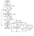
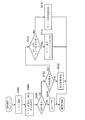
- FIG. 4 is a subroutine flowchart showing a processing procedure in a second embodiment of a glow plug diagnosis method applied to the glow plug drive control device shown in FIG. 1, and showing a processing procedure when a key switch is turned on.
- FIG. 4 is a subroutine flowchart showing a processing procedure in a second embodiment of a glow plug diagnosis method applied to the glow plug drive control device shown in FIG. 1 and showing a processing procedure when a key switch is turned off.
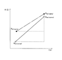
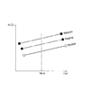
- It is a characteristic diagram which shows the example of a time change of the resistance value of a glow plug. It is a characteristic diagram which shows the example of a time change of the resistance value after the key switch is turned off.
- a glow plug drive control device (hereinafter referred to as “GCU”) 100 according to an embodiment of the present invention will be described with reference to FIG.
- the GCU 100 according to the present invention is roughly divided into an energization drive circuit 51, a measurement circuit 52, and an arithmetic control unit (indicated as “CPU” in FIG. 1) 53.
- the energization drive circuit 51 is configured such that energization control of the glow plug 1 is possible with the energization control semiconductor element 2 and the shunt resistor 3 as main components. That is, first, for example, a MOS FET or the like is used for the energization control semiconductor element 2, the drain is on the positive side of the vehicle battery 4, and the source is on the positive side of the glow plug 1 via the shunt resistor 3. The negative side of the glow plug 1 is connected to ground. In addition, a control signal from the arithmetic control unit 53 is applied to the gate of the energization control semiconductor element 2 so that conduction and non-conduction of the energization control semiconductor element 2 can be controlled.
- a MOS FET or the like is used for the energization control semiconductor element 2
- the drain is on the positive side of the vehicle battery 4
- the source is on the positive side of the glow plug 1 via the shunt resistor 3.
- the negative side of the glow plug 1 is connected
- the measurement circuit 52 has an operational amplifier 5 and an analog / digital converter (indicated as “A / D” in FIG. 1) 6 as main components, and the voltage drop in the shunt resistor 3 is arithmetically controlled as a digital signal.
- the unit 53 is configured to be supplied. That is, first, a voltage across the shunt resistor 3 is input to the operational amplifier 5, and the input voltage is amplified to a voltage suitable for the input of the analog / digital converter 6 in the next stage. Is output. The output voltage of the operational amplifier 5 is inputted to the arithmetic control unit 53 as a digital value by the analog / digital converter 6.
- the arithmetic control unit 53 includes, for example, a memory element (not shown) such as a RAM or a ROM centering on a microcomputer (not shown) and an ASIC (Application Specific Integrated Circuit) having a known and well-known configuration. And an interface circuit (not shown) for outputting a control signal for the energization control semiconductor element 2 as a main component.
- a drive control process of the glow plug 1, a glow plug diagnosis process described later, and the like are executed.
- the GCU 100 configured as described above includes an engine control electronic control unit (indicated as “ECU” in FIG. 1) 200 that executes a drive control process, a fuel injection control process, and the like of an engine (not shown). Accordingly, a target applied voltage to the glow plug 1 is input and instructed in a predetermined signal format.
- the engine control electronic control unit 200 performs engine operation control, fuel injection control, and the like (not shown), and calculates and calculates an applied voltage to the glow plug 1 according to the engine operating state, and supplies the calculation control unit 53 with the calculation control unit 53. It comes to direct.
- the setting information of the key switch (indicated as “KSW” in FIG. 1) 11, that is, information when the key switch 11 is set to the ON position, and Information when the key switch 11 is set to the start position is input.
- the GCU 100 and the engine control electronic control unit 200 are supplied with the power supply voltage from the vehicle battery 4 through a path (not shown) and can be started.
- the subroutine flowchart shown in FIG. 2 is one subroutine process that is executed together with the energization drive control of the glow plug 1 that is executed in the arithmetic control unit 53 as in the prior art.
- the subroutine processing shown in FIG. 2 is executed when the key switch 11 is turned on.
- Step S102 when the processing is started by the arithmetic control unit 53 by turning on the key switch 11, energization for starting is started and a required voltage is applied as in the normal driving of the glow plug 1 (FIG. 2).
- the engine not shown
- diagnosis it is determined whether or not diagnosis is possible (see step S104 in FIG. 2). That is, it is determined whether or not a predetermined diagnostic condition suitable for executing the following diagnostic processing is satisfied.
- examples of the predetermined diagnosis condition include execution time.
- the diagnosis condition is whether or not a predetermined execution time at which this series of diagnosis processes is to be executed has been reached. More specifically, whether or not it is a predetermined execution time is preferably determined by using, for example, the driving time of the vehicle, the travel distance of the vehicle, or the like as a determination index.
- the diagnosis is executed every time the vehicle is driven. You may make it do.
- whether or not the temperature of the engine coolant is in an appropriate range may be used as a diagnostic condition.
- step S104 determines whether the predetermined diagnosis condition is satisfied (in the case of YES). If it is determined in step S104 that the predetermined diagnosis condition is satisfied (in the case of YES), the process proceeds to step S106 described below, and it is determined that the predetermined diagnosis condition is not satisfied. In the case of NO (in the case of NO), it is determined that the state is not suitable for executing the subsequent series of processes, and the series of processes is terminated, and the process returns to the main routine (not shown).
- step S106 resistance value inclination data at the time of starting is acquired.
- the resistance value of the glow plug generally increases with time as indicated by the solid characteristic line in FIG. 5 after the start of energization until the appropriate energization time elapses. Is as conventionally known.
- “Rini” is the glow plug resistance value at the start of energization of the glow plug
- “Rsat” is the time when an appropriate energization time has elapsed after startup and the change in the resistance value of the glow plug is stabilized. It is the resistance value of the glow plug.
- the resistance value Rini at the start of energization of the glow plug is shortly after the energization of the glow plug is started, so that the glow plug does not generate enough heat and is in a state close to room temperature.
- the resistance value Rini is a room temperature resistance value.
- the resistance value Rsat is a resistance value at a time when an appropriate energization time has elapsed after the start and the change in the resistance value of the glow plug is stabilized. In other words, the change in the resistance value due to the heat generation of the glow plug is saturated. It is a resistance value in a state (in other words, a state where heat generation is saturated), that is, a saturation resistance value.
- “normal” means that the glow plug is in a normal state
- “aging” means that the glow plug has deteriorated.
- the resistance value Rini of the glow plug 1 at the start of energization of the glow plug 1 and the time when the resistance value after an appropriate energization time has elapsed from the start of energization has stabilized.
- the resistance value Rsat of the glow plug 1 is plotted on orthogonal coordinates with the horizontal axis representing the elapsed time from the start of energization and the vertical axis representing the resistance value
- the slope of the straight line connecting the two points is plotted as follows: It is defined as “resistance slope”.
- the “resistance slope” refers to the resistance value Rini of the glow plug 1 at the start of energization of the glow plug 1 and the glow value after a predetermined time has elapsed since acquisition of the resistance value Rini, instead of the above definition.
- a value calculated in the same manner as described above from the resistance value of the plug 1 may be used as the “resistance value inclination”.
- the resistance value of the glow plug 1 after elapse of a predetermined time does not necessarily need to be a saturated value.
- step S106 first, the resistance value of the glow plug 1 when starting energization (see step 102 in FIG. 2) is started (hereinafter referred to as “room temperature resistance value” for convenience of explanation) Rini, A resistance value Rsat after the energization time has elapsed (hereinafter referred to as “saturation resistance value” for convenience of explanation) is calculated based on the voltage drop of the shunt resistor 3 input via the analog / digital converter 6.
- saturation resistance value is calculated based on the voltage drop of the shunt resistor 3 input via the analog / digital converter 6.
- an appropriate energization time when obtaining the saturation resistance value Rsat is determined as a time sufficient to obtain the saturation resistance value, and specific electrical characteristics and applied voltage of the glow plug 1 are determined. It is preferable to determine based on the test and simulation results in consideration of the above.
- the resistance value of the glow plug 1 is obtained by arithmetic processing in the arithmetic control unit 53 as follows.
- the voltage drop of the glow plug 1 is obtained by subtracting the sum of the voltage drop of the shunt resistor 3 and the voltage drop of the energization control semiconductor element 2 from the voltage of the vehicle battery 4.
- the voltage of the vehicle battery 4 since the actual voltage is usually acquired in the diagnostic processing or the like in the engine control electronic control unit 200, it is sufficient to use the data, but the actual voltage Instead of this, a nominal value may be used simply.
- the standard value of the voltage drop of the energization control semiconductor element 2 is known in advance, it is determined as a constant and used for the above-described arithmetic processing.
- the energization current of the glow plug 1 is the same as the current flowing through the shunt resistor 3, and the resistance value of the shunt resistor 3 is grasped in advance and stored as a constant in an appropriate storage area of the arithmetic control unit 53. Therefore, it is obtained by dividing the actually measured voltage drop of the shunt resistor 3 by the resistance value of the shunt resistor 3 stored in advance in the arithmetic control unit 53 as a constant.
- the resistance value of the glow plug 1 is obtained by dividing the voltage drop of the glow plug 1 thus obtained by the energization current of the glow plug 1.
- the room temperature resistance value Rini and the saturation resistance value Rsat can be obtained.
- Whether the saturation resistance value Rsat is to be obtained is preferably set based on test results, simulation results, and the like in consideration of the electrical characteristics of each glow plug 1 and the drive control method.
- the difference between the saturation resistance value Rsat and the room temperature resistance value Rini is calculated as the time difference between the time when the room temperature resistance value Rini is obtained and the time when the saturation resistance value Rsat is obtained, in other words, the room temperature resistance value Rini is calculated.
- the time difference between the time when the voltage drop of the shunt resistor 3 for reading is read into the calculation control unit 53 and the time when the voltage drop of the shunt resistor 3 for calculating the saturation resistance value Rsat is read into the calculation control unit 53
- the result of division is obtained as the resistance value slope at the start.
- the resistance value inclination obtained as described above is equal to or larger than the first inclination reference value a (see step S108 in FIG. 2), and the resistance value inclination is equal to or larger than the first inclination reference value a. If it is determined (YES), it is determined that the glow plug 1 is normal (see step S110 in FIG. 2), a series of processing is terminated, and the process returns to the main routine (not shown).
- the resistance value of the glow plug 1 increases with the elapse of time from the start of energization, and it is generally well known that the resistance value changes with time, that is, there is a slope of the resistance value as described above. By the way.
- the inventor of the present application has increased the room temperature resistance value as the deterioration of the glow plug 1 proceeds, and as a result, the resistance value inclination becomes smaller.
- the characteristic line indicated by a solid line shows an example of the resistance slope of a glow plug that has just been used, but the characteristic line indicated by a two-dot chain line indicates that glow plug. It shows an example of the resistance value inclination when it deteriorates due to long-term use of the material, and it can be confirmed that the resistance value inclination is smaller than that at the beginning of use.
- the inventor of the present application has come to the conclusion that the deterioration of the glow plug can be determined based on the slope of the resistance value of the glow plug. This is based on the research results of those who have studied.
- the first inclination reference value a is appropriately determined based on test results, simulation results, and the like in consideration of the electrical characteristics of the glow plug 1 and the operating conditions of the apparatus used. The value should be set.
- step S108 determines whether the resistance value inclination is not greater than or equal to the first inclination reference value a (in the case of NO)
- the process proceeds to step S112, where the resistance value inclination is the second inclination reference value b.
- the resistance value inclination is the second inclination reference value b.
- the correction coefficient for correcting the voltage applied to the glow plug 1 is calculated so that the voltage can be continuously used by correcting the voltage applied to the glow plug 1 (FIG. 2). Step S114).
- This correction coefficient is calculated by an arithmetic expression set in advance based on a test or simulation result so that an appropriate value is determined according to the resistance value inclination.
- the calculated and calculated correction coefficient is stored in an appropriate storage area of the engine control electronic control unit 200 and is appropriately used for energization drive control of the glow plug 1. Therefore, after the process of step S114, the process returns to the main routine (not shown).
- step S112 when it is determined in step S112 that the resistance value inclination is not in the range not less than the second inclination reference value b and less than the first inclination reference value a (in the case of NO), that is, the second inclination reference.
- the resistance value inclination data is stored in the appropriate storage areas of the arithmetic control unit 53 and the engine control electronic control unit 200 as resistance value inclination abnormality data of the glow plug 1. It is stored (see step S116 in FIG. 2).
- a predetermined warning lamp (not shown) such as a so-called MIL lamp is turned on (step S118 in FIG. 2). Return to the main routine.
- the deterioration of the glow plug 1 can be diagnosed by executing the processing described below when the key switch 11 is turned on and when the key switch 11 is turned off. It is what.
- the procedure of the diagnostic process executed when the key switch 11 is turned on will be described with reference to the subroutine flowchart shown in FIG.
- the processing of steps S202 to S214 is basically the same as the processing of steps S102 to S114 shown in FIG. 2, and therefore detailed description thereof is omitted here.
- step S212 If it is determined in step S212 that the resistance value gradient is not less than the second gradient reference value b and less than the first gradient reference value a (in the case of NO), that is, the second gradient reference value b. If it is less than, it is determined whether or not a temporary error determination has been made when the key switch 11 is turned off immediately (see step S216 in FIG. 3).
- the error temporary determination is a provisional determination that the glow plug 1 is abnormal, as will be described in detail in step S220 described later. Therefore, in step S216, when it is determined that the temporary error determination has been made when the key switch 11 is turned off immediately (in the case of YES), the error is confirmed, that is, the glow plug 1 is surely abnormal. As shown in FIG.
- a predetermined warning lamp such as a so-called MIL lamp is turned on (see step S218 in FIG. 3), a series of processing is terminated, and the process returns to the main routine (not shown).
- a predetermined warning lamp such as a so-called MIL lamp is turned on (see step S218 in FIG. 3), a series of processing is terminated, and the process returns to the main routine (not shown).
- step S218 it is determined in step S212 that the resistance value inclination is not in a range that is equal to or larger than the second inclination reference value b and lower than the first inclination reference value a. Since the temporary error determination is made when the key switch 11 is turned off most recently, the abnormality of the glow plug 1 is sure, that is, the error is confirmed.
- step S216 if it is determined in step S216 that the error tentative determination has not been made when the key switch 11 is turned off most recently (in the case of NO), the resistance value inclination is changed to the second inclination in step S212 first. Since it is the first time after the key switch 11 has been turned off immediately after the key switch 11 has been determined that it is not less than the reference value b and less than the first inclination reference value a, there is a possibility that the glow plug 1 is abnormal. As the temporary error determination, the occurrence of the temporary error determination is stored and held in appropriate storage areas of the arithmetic control unit 53 and the engine control electronic control unit 200 (FIG. 3). (See step S220).
- a correction coefficient for correcting the voltage applied to the glow plug 1 is calculated (see step S222 in FIG. 3).
- the calculation of the correction coefficient is basically the same as the correction coefficient calculation process in step S114 in FIG.
- the calculated correction coefficient is stored in an appropriate storage area of the engine control electronic control unit 200, and is used for correcting the voltage applied to the glow plug 1 at the next start.
- a series of processes are terminated, and the process returns to the main routine (not shown).
- diagnostic processing executed when the key switch 11 is off will be described with reference to a subroutine flowchart shown in FIG. Note that the processing described below is in a so-called after-run state in which drive control of an engine (not shown) is stopped and operation diagnosis of the vehicle device is executed, and the key switch 11 is described as follows. Is to be executed when is turned off. Accordingly, when the processing by the arithmetic control unit 53 is started by turning off the key switch 11, test energization to the glow plug 1 is performed (see step S302 in FIG. 4).
- This test energization replaces the start energization (step S102 in FIG. 2) in the first embodiment described above with reference to FIG. 2, and thereafter the resistance value of the glow plug 1 after energization is obtained.
- the voltage applied to the glow plug 1 and the energization time which are appropriately determined in advance, are performed. It should be noted that it is preferable to determine what applied voltage and energization time are appropriate based on the results of tests and simulations in consideration of the specifications of the glow plug 1 and the specifications of the entire apparatus.
- the resistance value of the glow plug 1 is acquired (see step S304 in FIG. 4). Note that the resistance value of the glow plug 1 is the same as that described in step S106 in the first embodiment described above with reference to FIG. 2, and therefore detailed description thereof is omitted here. .
- the glow plug 1 is determined to be normal based on the research results of the present inventor as described below.
- the inventor of the present application has found that the resistance value after the key switch 11 is turned off increases as the usage time and years of the glow plug 1 elapse. I came to get.
- FIG. 6 shows an example of the change in the resistance value of the glow plug when the test switch is energized after the key switch 11 is turned off.
- the horizontal axis represents the key switch 11.
- the elapsed time from the off time and the vertical axis indicate the resistance value of the glow plug, respectively.
- the solid characteristic line indicates the resistance change characteristic when the glow plug has just begun use
- the two-dot chain characteristic line indicates the resistance change characteristic when the glow plug is in a deteriorated state.
- the characteristic line of the alternate long and short dash line represents the change characteristic of the resistance value when the deterioration is further advanced and it is determined that the glow plug is broken. From this characteristic line, it can be confirmed that the resistance value increases as the glow plug deteriorates.
- step S306 the determination process in step S306 is based on the research result of the present inventor.
- the resistance value of the glow plug 1 is not less than or equal to the first reference resistance value c (in the case of NO)
- the resistance value of the glow plug 1 becomes equal to the first reference resistance value c. It is determined whether or not it exceeds the second reference resistance value d (see step S310 in FIG. 4).
- step S310 If it is determined in step S310 that the resistance value of the glow plug 1 is in the range exceeding the first reference resistance value c and not more than the second reference resistance value d (in the case of YES), the glow plug 1
- the correction coefficient for correcting the voltage applied to the glow plug 1 is calculated so that the voltage can be continuously used by correcting the voltage applied to the glow plug 1 according to the deterioration state. (See step S312 in FIG. 4).
- This correction coefficient is calculated by an arithmetic expression set in advance based on a test or simulation result so that an appropriate value is determined according to the acquired resistance value of the glow plug 1.
- the calculated and calculated correction coefficient is stored in an appropriate storage area of the engine control electronic control unit 200 and is appropriately used for energization drive control of the glow plug 1.
- step S310 when it is determined in step S310 that the resistance value of the glow plug 1 is not in the range exceeding the first reference resistance value c and not more than the second reference resistance value d (NO), that is, If it exceeds the 2 reference resistance value d, it is determined whether or not a temporary error determination has been made when the key switch 11 is turned on most recently (see step S314 in FIG. 4).
- step S314 if it is determined that a temporary error determination has been made when the key switch 11 is most recently turned on (in the case of YES), it is determined that the error has been confirmed, that is, the abnormality of the glow plug 1 is certain.
- a reservation state is made so that a warning operation is performed (see step S316 in FIG. 4), and a series of processing is terminated, and the process returns to a main routine (not shown). That is, a predetermined command or the like is stored in an appropriate non-volatile storage area of the arithmetic control unit 53 so that an alarm action is executed when the key switch 11 is turned on next time. State.
- the alarm operation is typified by, for example, lighting processing of a predetermined warning light (not shown) such as a so-called MIL lamp, but the present invention is not limited to this, and instead of lighting the warning light. Alternatively, it is preferable to perform warning sound generation, voice notification, or the like together with the lighting of the warning lamp.
- step S314 if it is determined in step S314 that the temporary error determination has not been made when the key switch 11 is most recently turned on (in the case of NO), the resistance value of the glow plug 1 is first changed in step S310. Since it is the first time since the key switch 11 has been turned on for the first time that the reference resistance value c exceeds the second reference resistance value d and is not less than the second reference resistance value d, there is a possibility that the glow plug 1 is abnormal. As a provisional error determination, the occurrence of a temporary error determination is stored and held in appropriate storage areas of the arithmetic control unit 53 and the engine control electronic control unit 200 (FIG. 4). Step S318). As described above, in the second embodiment, diagnostic processing is executed each time the key switch 11 is turned on and off, thereby further improving the reliability and reliability of the glow plug diagnostic processing. Will be.
Landscapes
- Engineering & Computer Science (AREA)
- Chemical & Material Sciences (AREA)
- Combustion & Propulsion (AREA)
- Mechanical Engineering (AREA)
- General Engineering & Computer Science (AREA)
- Combined Controls Of Internal Combustion Engines (AREA)
Abstract
Description
例えば、特許文献1には、グロープラグの上流側の電圧と下流側の電圧を検出し、その電圧差によってグロープラグの断線を判定可能とした装置が開示されている。
さらに、特許文献3には、複数の時点においてグロープラグの抵抗値を検出し、検出された抵抗値に応じて、グロープラグの印加電圧を補正するよう構成された装置が開示されている。
また、特許文献3に開示された従来装置にあっては、印加電圧の補正を行うのみでは、却ってグロープラグの劣化を促進させる虞があるという問題がある。
かかる構成において、前記抵抗値傾きが、予め定められた第2傾き基準値を下回る場合に、前記グロープラグの異常と判定するよう構成すると好適である。
本発明の第2の形態によれば、グロープラグの駆動制御を実行する演算制御部と、前記演算制御部により実行されるグロープラグの駆動制御に応じて、前記グロープラグの通電を行う通電駆動回路とを具備してなる車両用グロープラグ駆動制御装置であって、
前記演算制御部は、
車両のキースイッチがオンとされた際に、前記グロープラグへ対して予め定めた通電を行い、前記グロープラグの通電開始時における抵抗値と、前記グロープラグの通電後、所定時間経過後における前記グロープラグの抵抗値とを、前記グロープラグへの印加電圧と通電電流を基に算出すると共に、当該算出された抵抗値を基に、時間経過に対する抵抗値の変化の割合を抵抗値傾きとして算出し、前記抵抗値傾きが予め定められた第1傾き基準値を超えている場合に、前記グロープラグが正常と判定するよう構成されてなるものが提供される。
かかる構成において、前記演算制御部は、前記抵抗値傾きが、予め定められた第2傾き基準値を下回る場合に、前記グロープラグの異常と判定するよう構成すると好適である。
3…シャント抵抗器
5…演算増幅器
6…アナログ・ディジタル変換器
51…通電駆動回路
52…計測回路
53…演算制御部
100…グロープラグ駆動制御装置
200…エンジン制御用電子制御ユニット
なお、以下に説明する部材、配置等は本発明を限定するものではなく、本発明の趣旨の範囲内で種々改変することができるものである。
最初に、本発明の実施の形態におけるグロープラグ駆動制御装置(以下「GCU」と称する)100について、図1を参照しつつ説明する。
本発明におけるGCU100は、通電駆動回路51と、計測回路52と、演算制御部(図1においては「CPU」と表記)53とに大別されて構成されたものとなっている。
すなわち、まず、通電制御用半導体素子2は、例えば、MOS FETなどが用いられ、そのドレインは、車両用バッテリ4の正極に、ソースは、シャント抵抗器3を介してグロープラグ1の正極側に接続され、グロープラグ1の負極側は、アースに接続されたものとなっている。また、通電制御用半導体素子2のゲートには、演算制御部53からの制御信号が印加されるようになっており、通電制御用半導体素子2の導通、非導通が制御可能となっている。
すなわち、まず、演算増幅器5には、シャント抵抗器3の両端の電圧が入力されるようになっており、その入力電圧は、次段のアナログ・ディジタル変換器6の入力に適した電圧に増幅され、出力されるようになっている。そして、演算増幅器5の出力電圧は、アナログ・ディジタル変換器6によりディジタル値として演算制御部53に入力されるようになっている。
かかる演算制御部53においては、グロープラグ1の駆動制御処理や、後述するグロープラグ診断処理等が実行されるものとなっている。
エンジン制御用電子制御ユニット200は、図示されないエンジンの動作制御や燃料噴射制御等を行う他、エンジンの動作状況に応じたグロープラグ1への印加電圧を演算算出し、演算制御部53へ対して指示するようになっている。
GCU100、及び、エンジン制御用電子制御ユニット200は、キースイッチ11がオンとされると図示されない経路によって車両用バッテリ4からの電源電圧の供給を受けて、始動できるようになっている。
なお、グロープラグ1の駆動制御の手法は種々あるが、本発明の実施の形態におけるグロープラグ診断方法を適用するにあたっては、特定の駆動制御に限定される必要はなく、装置の使用条件等に応じて適宜な駆動制御方法を採り得るものである。
まず、図2に示されたサブルーチンフローチャートは、演算制御部53において従来同様実行されるグロープラグ1の通電駆動制御などと共に実行される1つのサブルーチン処理となっているものである。
また、この図2に示されたサブルーチン処理は、キースイッチ11がオンとされた際に実行されるものとなっている。
次いで、診断が可能か否かが判定される(図2のステップS104参照)。
すなわち、以下の診断処理を実行するに適した所定の診断条件が満足されているか否かが判定される。
なお、このように、車両の運転時間が所定時間経過する毎、又は、車両の走行距離が所定走行距離となる毎に診断を実行することに代えて、車両が運転される毎に診断を実行するようにしても良い。
さらに、例えば、エンジン冷却水の温度が適正範囲にあるか否かを、診断条件としても良い。
一般に、グロープラグの抵抗値は、通電が開始されて、その後、適宜な通電時間が経過するまでの間に、図5において実線の特性線で示されたように概ね時間の経過と共に上昇することは従来から知られている通りである。なお、図5において、「Rini」 は、グロープラグの通電開始時におけるグロープラグの抵抗値、「Rsat」は、始動後適宜な通電時間が経過してグロープラグの抵抗値変化が安定した時点におけるグロープラグの抵抗値である。
ここで、グロープラグの通電開始時における抵抗値Riniは、グロープラグの通電が開始されて間もないため、グロープラグの発熱は不十分であり、大凡常温に近い状態であるため、その意味で抵抗値Riniは、いわば常温抵抗値である。
また、抵抗値Rsatは、始動後適宜な通電時間が経過してグロープラグの抵抗値変化が安定した時点における抵抗値であるが、別言すれば、グロープラグの発熱による抵抗値の変化が飽和した状態(換言すれば、発熱が飽和した状態)における抵抗値であり、いわば飽和抵抗値である。
本発明の実施の形態においては、上述のようにグロープラグ1へ通電を開始し始めた時点のグロープラグ1の抵抗値Riniと、通電開始から適宜な通電時間経過後における抵抗値が安定した時点におけるグロープラグ1の抵抗値Rsatを、横軸を通電開始時からの経過時間、縦軸を抵抗値とする直交座標上に、それぞれプロットした場合に、その2点間を結ぶ直線の傾きを、「抵抗値傾き」と定義する。
なお、「抵抗値傾き」は、上述の定義に代えて、グロープラグ1へ通電を開始し始めた時点のグロープラグ1の抵抗値Riniと、抵抗値Riniの取得時から所定時間経過後のグロープラグ1の抵抗値とから、上述したと同様にして算出した値を「抵抗値傾き」としても良い。この場合、所定時間経過後のグロープラグ1の抵抗値は、必ずしも飽和した状態の値である必要はない。
なお、飽和抵抗値Rsatを取得する際の、”適宜な通電時間経過後”は、飽和抵抗値を得るに十分な時間として定められるもので、グロープラグ1の具体的な電気的特性や印加電圧等を考慮して試験やシミュレーション結果に基づいて定めるのが好適である。
まず、最初に、車両用バッテリ4の電圧から、シャント抵抗器3の電圧降下と通電制御用半導体素子2の電圧降下の和が減算されて、グロープラグ1の電圧降下が求められる。ここで、車両用バッテリ4の電圧は、通常、エンジン制御用電子制御ユニット200における診断処理等において実際の電圧が取得されるようになっているため、そのデータを流用すれば足りるが、実電圧に代えて、簡易的に公称値を用いるようにしても良い。また、通電制御用半導体素子2の電圧降下も予め標準値が把握されているため、定数として定めておき、これを上述の演算処理に用いれば良い。
このようにして求められたグロープラグ1の電圧降下を、グロープラグ1の通電電流で除することで、グロープラグ1の抵抗値が求められる。
ここで、抵抗値傾きによりグロープラグ1の劣化を判定する根拠について説明する。
グロープラグ1の抵抗値は、通電開始から時間の経過と共に上昇し、時間変化に対する抵抗値の変化、すなわち、抵抗値傾きがあることは、先に述べた通り、一般的に良く知られているところである。
なお、ステップS108において、第1傾き基準値aは、グロープラグ1の電気的特性や、使用される装置の運転条件等を考慮して、試験結果やシミュレーション結果等に基づいて、ここに適切な値が設定されるべきものである。
そして、抵抗値傾きが、第2傾き基準値b以上で、かつ、第1傾き基準値aを下回っていると判定された場合(YESの場合)には、グロープラグ1がある程度劣化しているものの、その劣化状態に応じて、グロープラグ1への印加電圧を補正することで継続使用可能として、グロープラグ1の印加電圧を補正するための補正係数の算出が行われることとなる(図2のステップS114参照)。
しかして、ステップS114の処理後は、図示されないメインルーチンへ戻ることとなる。
また、同時に、グロープラグ1の異常であるとして、いわゆるMILランプ等の所定の警告灯(図示せず)の点灯処理がなされ(図2のステップS118)、一連の処理が終了されて、図示されないメインルーチンへ戻ることとなる。
この第2の実施例は、キースイッチ11がオンされた際と、キースイッチ11がオフとされた際の各々において以下に説明する処理を実行することで、グロープラグ1の劣化の診断を可能としたものである。
最初に、図3に示されたサブルーチンフローチャートを参照しつつ、キースイッチ11がオンされた際に実行される診断処理の手順について説明する。
まず、ステップS202~S214の処理は、図2で示されたステップS102~S114までの処理と基本的に同一であるので、ここでの再度の詳細な説明は省略する。
しかして、ステップS216において、キースイッチ11の直近のオフ時に、エラー仮判定がなされていると判定された場合(YESの場合)には、エラー確定、すなわち、グロープラグ1の異常が確実であるとして、いわゆるMILランプ等の所定の警告灯(図示せず)の点灯処理がなされ(図3のステップS218参照)、一連の処理が終了されて、図示されないメインルーチンへ戻ることとなる。
このように、このステップS218では、先にステップS212において、抵抗値傾きが、第2傾き基準値b以上で、かつ、第1傾き基準値aを下回る範囲ではないと判定されていることと、キースイッチ11の直近のオフ時に仮エラー判定がなされていることから、グロープラグ1の異常が確実、すなわち、エラー確定としている。
算出された補正係数は、エンジン制御用電子制御ユニット200の適宜な記憶領域に記憶され、次回の始動の際にグロープラグ1の印加電圧の補正に用いられることとなる。このステップS222の処理後は、一連の処理が終了され、図示されないメインルーチンへ戻ることとなる。
なお、以下に説明する処理は、エンジン(図示せず)の駆動制御が停止されて、車両装置の動作診断等が実行される、いわゆるアフターラン状態にあって、以下に述べるようにキースイッチ11がオフされた際に実行されるものとなっているものである。
しかして、キースイッチ11がオフされることにより演算制御部53による処理が開始されると、グロープラグ1へのテスト通電が行われる(図4のステップS302参照)。
次いで、上述の取得されたグロープラグ1の抵抗値が第1基準抵抗値c以下であるか否かが判定され(図4のステップS306参照)、グロープラグ1の抵抗値が第1基準抵抗値c以下であると判定された場合(YESの場合)には、グロープラグ1は正常であると判定されて(図4のステップS308参照)、一連の処理が終了され、図示されないメインルーチンへ戻ることとなる。
まず、本願発明者は、キースイッチ11のオフ後の抵抗値について鋭意研究の結果、キースイッチ11のオフ後の抵抗値は、グロープラグ1の使用時間、年数が経過するに従い上昇するという知見を得るに至った。
図6には、キースイッチ11オフ後のテスト通電時のグロープラグの抵抗値の変化の一例が示されており、同図について説明すれば、まず、同図において、横軸はキースイッチ11のオフ時からの経過時間を、縦軸は、グロープラグの抵抗値を、それぞれ示している。
同図において、実線の特性線は、グロープラグが使用開始間もない時点における抵抗値の変化特性を、二点鎖線の特性線は、グロープラグが劣化状態にある場合の抵抗値の変化特性を、一点鎖線の特性線は、劣化がさらに進み、グロープラグの故障と判断される際の抵抗値の変化特性を、それぞれ表したものである。
この特性線から、グロープラグの劣化が進むに従い、抵抗値が上昇することが確認できる。
一方、ステップS306において、グロープラグ1の抵抗値が第1基準抵抗値c以下ではないと判定された場合(NOの場合)には、グロープラグ1の抵抗値が、第1基準抵抗値cを超え、かつ、第2基準抵抗値d以下であるか否かが判定される(図4のステップS310参照)。
この補正係数は、取得されたグロープラグ1の抵抗値に応じて適切な値が定まるよう、試験やシミュレーション結果に基づいて予め設定された演算式により演算算出されるものとなっている。そして、演算算出された補正係数は、エンジン制御用電子制御ユニット200の適宜な記憶領域に記憶され、グロープラグ1の通電駆動制御に適宜供されるようになっている。
一方、ステップS310において、グロープラグ1の抵抗値が、第1基準抵抗値cを超え、かつ、第2基準抵抗値d以下の範囲ではないと判定された場合(NOの場合)、すなわち、第2基準抵抗値dを上回っている場合には、キースイッチ11の直近のオン時に、エラー仮判定がなされたか否かが判定される(図4のステップS314参照)。
すなわち、演算制御部53の記憶領域の内、不揮発性を有する適宜な記憶領域に、キースイッチ11が次回、オンとされた際に警報動作が実行せしめられるよう所定のコマンド等が記憶され、予約状態とされる。そして、キースイッチ11が次回、オンとされた際に、このコマンド等が解読され、警報動作が実行されるようになっている。
ここで、警報動作は、例えば、いわゆるMILランプ等の所定の警告灯(図示せず)の点灯処理に代表されるものであるが、これに限定される必要はなく、警告灯の点灯に代えて、又は、警告灯の点灯と共に、警告音の発生や音声による報知等を行うのが好適である。
このように、第2の実施例においては、キースイッチ11のオン時とオフ時のそれぞれにおいて、診断処理を実行することにより、グロープラグ診断処理のより一層の信頼性、確実性の向上が確保されることとなる。
Claims (12)
- 車両のキースイッチがオンとされた際に、グロープラグへ対して予め定めた通電を行い、前記グロープラグの通電開始時における抵抗値と、前記グロープラグの通電後、所定時間経過後における前記グロープラグの抵抗値とを測定し、時間経過に対する抵抗値の変化の割合を抵抗値傾きとして算出し、前記抵抗値傾きが予め定められた第1傾き基準値を超えている場合に、前記グロープラグが正常と判定することを特徴とするグロープラグ診断方法。
- 前記抵抗値傾きが、予め定められた第2傾き基準値を下回る場合に、前記グロープラグの異常と判定することを特徴とする請求項1記載のグロープラグ診断方法。
- 前記抵抗値傾きが、予め定められた第2傾き基準値以上であって、かつ、前記第1傾き基準値を下回る範囲内にある場合に、予め取得されている前記グロープラグの正常時における抵抗値傾きとの差を基に、前記グロープラグの通電の際の印加電圧の補正係数を算出し、前記補正係数を用いて前記印加電圧を補正することを特徴とする請求項2記載のグロープラグ診断方法。
- 前記抵抗値傾きが、予め定められた第2傾き基準値を下回る場合に、前記キースイッチの直近のオフ時に、エラー仮判定が記憶されているか否かを判定し、前記エラー仮判定が記憶されていないと判定された場合に、エラー仮判定が生じたことを記憶する一方、前記エラー仮判定が記憶されていると判定された場合に、前記グロープラグの異常と判定し、
前記エラー仮判定が記憶された後、前記キースイッチがオフされた際に、前記グロープラグへ予め定められたテスト通電を行い、前記通電を終了する際に前記グロープラグの抵抗値を計測し、前記抵抗値が第1基準抵抗値以下である場合に、前記グロープラグが正常と判定することを特徴とする請求項1記載のグロープラグ診断方法。 - 前記キースイッチがオフされた際の前記テスト通電後において、前記グロープラグの抵抗値が、第2基準抵抗値を上回る場合に、前記キースイッチの直近のオン時に、エラー仮判定が記憶されているか否かを判定し、前記エラー仮判定が記憶されていないと判定された場合に、エラー仮判定が生じたことを記憶する一方、前記エラー仮判定が記憶されていると判定された場合に、前記グロープラグの異常と判定すると共に、次回、キースイッチがオンされた際に警告動作を行い得るよう予約状態とすることを特徴とする請求項4記載のグロープラグ診断方法。
- 前記グロープラグの抵抗値が、前記第1基準抵抗値を上回り、かつ、第2基準抵抗値以下の範囲内にある場合に、予め取得されている前記グロープラグの正常時における抵抗値との差を基に、前記グロープラグの通電の際の印加電圧の補正係数を算出し、前記補正係数を用いて前記印加電圧を補正することを特徴とする請求項5記載のグロープラグ診断方法。
- グロープラグの駆動制御を実行する演算制御部と、
前記演算制御部により実行されるグロープラグの駆動制御に応じて、前記グロープラグの通電を行う通電駆動回路とを具備してなる車両用グロープラグ駆動制御装置であって、
前記演算制御部は、
車両のキースイッチがオンとされた際に、前記グロープラグへ対して予め定めた通電を行い、前記グロープラグの通電開始時における抵抗値と、前記グロープラグの通電後、所定時間経過後における前記グロープラグの抵抗値とを、前記グロープラグへの印加電圧と通電電流を基に算出すると共に、当該算出された抵抗値を基に、時間経過に対する抵抗値の変化の割合を抵抗値傾きとして算出し、前記抵抗値傾きが予め定められた第1傾き基準値を超えている場合に、前記グロープラグが正常と判定するよう構成されてなることを特徴とする車両用グロープラグ駆動制御装置。 - 前記演算制御部は、
前記抵抗値傾きが、予め定められた第2傾き基準値を下回る場合に、前記グロープラグの異常と判定するよう構成されてなることを特徴とする請求項7記載の車両用グロープラグ駆動制御装置。 - 前記演算制御部は、
前記抵抗値傾きが、予め定められた第2傾き基準値以上であって、かつ、前記第1傾き基準値を下回る範囲内にある場合に、予め取得されている前記グロープラグの正常時における抵抗値傾きとの差を基に、前記グロープラグの通電の際の印加電圧の補正係数を算出し、前記補正係数を用いて前記印加電圧を補正するよう構成されてなることを特徴とする請求項8記載の車両用グロープラグ駆動制御装置。 - 前記演算制御部は、
前記抵抗値傾きが、予め定められた第2傾き基準値を下回る場合に、前記キースイッチの直近のオフ時に、エラー仮判定が記憶されているか否かを判定し、前記エラー仮判定が記憶されていないと判定された場合に、エラー仮判定が生じたことを記憶する一方、前記エラー仮判定が記憶されていると判定された場合に、前記グロープラグの異常と判定し、
前記エラー仮判定が記憶された後、前記キースイッチがオフされた際に、前記グロープラグへ予め定められたテスト通電を行い、前記通電を終了する際に前記グロープラグの抵抗値を計測し、前記抵抗値が第1基準抵抗値以下である場合に、前記グロープラグが正常と判定するよう構成されてなることを特徴とする請求項7記載の車両用グロープラグ駆動制御装置。 - 前記演算制御部は、
前記キースイッチがオフされた際の前記テスト通電後において、前記グロープラグの抵抗値が、第2基準抵抗値を上回る場合に、前記キースイッチの直近のオン時に、エラー仮判定が記憶されているか否かを判定し、前記エラー仮判定が記憶されていないと判定された場合に、エラー仮判定が生じたことを記憶する一方、前記エラー仮判定が記憶されていると判定された場合に、前記グロープラグの異常と判定すると共に、次回、キースイッチがオンされた際に警告動作を可能とするよう構成されてなることを特徴とする請求項10記載の車両用グロープラグ駆動制御装置。 - 前記演算制御部は、
前記グロープラグの抵抗値が、前記第1基準抵抗値を上回り、かつ、第2基準抵抗値以下の範囲内にある場合に、予め取得されている前記グロープラグの正常時における抵抗値との差を基に、前記グロープラグの通電の際の印加電圧の補正係数を算出し、前記補正係数を用いて前記印加電圧を補正するよう構成されてなることを特徴とする請求項11記載の車両用グロープラグ駆動制御装置。
Priority Applications (3)
| Application Number | Priority Date | Filing Date | Title |
|---|---|---|---|
| EP13866528.6A EP2940288A4 (en) | 2012-12-27 | 2013-11-18 | Glow plug diagnosis method and device for controlling driving of vehicle glow plug |
| JP2014554231A JP5995993B2 (ja) | 2012-12-27 | 2013-11-18 | グロープラグ診断方法及び車両用グロープラグ駆動制御装置 |
| US14/652,502 US9822755B2 (en) | 2012-12-27 | 2013-11-18 | Glow plug diagnosis method and vehicle glow plug drive control apparatus |
Applications Claiming Priority (2)
| Application Number | Priority Date | Filing Date | Title |
|---|---|---|---|
| JP2012-283923 | 2012-12-27 | ||
| JP2012283923 | 2012-12-27 |
Publications (1)
| Publication Number | Publication Date |
|---|---|
| WO2014103554A1 true WO2014103554A1 (ja) | 2014-07-03 |
Family
ID=51020649
Family Applications (1)
| Application Number | Title | Priority Date | Filing Date |
|---|---|---|---|
| PCT/JP2013/080983 Ceased WO2014103554A1 (ja) | 2012-12-27 | 2013-11-18 | グロープラグ診断方法及び車両用グロープラグ駆動制御装置 |
Country Status (4)
| Country | Link |
|---|---|
| US (1) | US9822755B2 (ja) |
| EP (1) | EP2940288A4 (ja) |
| JP (1) | JP5995993B2 (ja) |
| WO (1) | WO2014103554A1 (ja) |
Families Citing this family (4)
| Publication number | Priority date | Publication date | Assignee | Title |
|---|---|---|---|---|
| DE102017115946A1 (de) | 2017-07-14 | 2019-01-17 | Borgwarner Ludwigsburg Gmbh | Verfahren zum Regeln der Temperatur einer Glühkerze |
| DE102019105618B3 (de) * | 2019-03-06 | 2020-07-30 | Borgwarner Ludwigsburg Gmbh | Verfahren zum Erkennen eines Glühkerzenwechsels |
| KR20220030652A (ko) | 2020-09-03 | 2022-03-11 | 현대자동차주식회사 | 엔진의 글로우플러그 단선 검출 방법 |
| CN223166865U (zh) * | 2024-07-31 | 2025-07-29 | 矽品精密工业股份有限公司 | 测试装置 |
Citations (6)
| Publication number | Priority date | Publication date | Assignee | Title |
|---|---|---|---|---|
| JPS5726275A (en) * | 1980-07-24 | 1982-02-12 | Nippon Denso Co Ltd | Method and device for detecting glow plug disconnection |
| JPS58172472A (ja) * | 1982-04-02 | 1983-10-11 | Nippon Denso Co Ltd | 加熱体の断線検出方法 |
| JPH11182400A (ja) | 1997-12-18 | 1999-07-06 | Isuzu Motors Ltd | グロープラグの断線検出システム |
| JP2002276524A (ja) | 2001-03-16 | 2002-09-25 | Ngk Spark Plug Co Ltd | 故障検出回路 |
| JP2008031979A (ja) * | 2006-07-06 | 2008-02-14 | Auto Network Gijutsu Kenkyusho:Kk | 異常検出装置 |
| JP2011185128A (ja) | 2010-03-05 | 2011-09-22 | Ngk Spark Plug Co Ltd | グロープラグ・エンジン始動装置制御システム |
Family Cites Families (17)
| Publication number | Priority date | Publication date | Assignee | Title |
|---|---|---|---|---|
| US5144922A (en) * | 1990-11-01 | 1992-09-08 | Southwest Research Institute | Fuel ignition system for compression ignition engines |
| JP4047762B2 (ja) * | 2002-05-14 | 2008-02-13 | 日本特殊陶業株式会社 | グロープラグの制御装置 |
| US8227726B2 (en) * | 2006-05-18 | 2012-07-24 | Ngk Spark Plug Co., Ltd. | Ceramic heater and glow plug |
| DE102006025834B4 (de) * | 2006-06-02 | 2010-05-12 | Beru Ag | Verfahren zum Steuern einer Glühkerze in einem Dieselmotor |
| JP4780056B2 (ja) * | 2007-08-01 | 2011-09-28 | 株式会社デンソー | グロープラグ劣化判定装置 |
| DE102009000232B4 (de) * | 2008-01-15 | 2019-10-31 | Denso Corporation | Vorrichtung zur Erfassung einer Verschlechterung eines Heizelements und Vorrichtung zur Steuerung einer Energiezufuhr einer Glühkerze |
| JP5179887B2 (ja) * | 2008-01-15 | 2013-04-10 | 株式会社オートネットワーク技術研究所 | グロープラグ制御装置及び制御方法 |
| DE102008007397A1 (de) * | 2008-02-04 | 2009-08-06 | Robert Bosch Gmbh | Verfahren zur Überwachung von wenigstens einer Glühstiftkerze eines Brennkraftmotors und Vorrichtung hierzu |
| DE102008007391A1 (de) * | 2008-02-04 | 2009-08-06 | Robert Bosch Gmbh | Ausfallfrüherkennung bei einer mit einer kontinuierlichen Folge von Spannungspulsen versorgten Glühkerze |
| JP4956486B2 (ja) * | 2008-05-30 | 2012-06-20 | 日本特殊陶業株式会社 | グロープラグ通電制御装置及びグロープラグ通電制御システム |
| US8423197B2 (en) * | 2008-11-25 | 2013-04-16 | Ngk Spark Plug Co., Ltd. | Apparatus for controlling the energizing of a heater |
| JP5393341B2 (ja) * | 2009-08-20 | 2014-01-22 | 株式会社デンソー | グロープラグ劣化判定装置 |
| JP5503422B2 (ja) * | 2010-06-11 | 2014-05-28 | 日本特殊陶業株式会社 | グロープラグの通電制御装置 |
| JP2011256821A (ja) * | 2010-06-11 | 2011-12-22 | Ngk Spark Plug Co Ltd | グロープラグの通電制御装置 |
| EP2759771B1 (en) * | 2011-09-20 | 2017-04-26 | Bosch Corporation | Glow plug diagnostic method and glow plug drive control device |
| DE102012102013B3 (de) * | 2012-03-09 | 2013-06-13 | Borgwarner Beru Systems Gmbh | Verfahren zur Regelung der Temperatur einer Glühkerze |
| JP5726275B2 (ja) | 2013-11-15 | 2015-05-27 | 三井化学株式会社 | 接着剤 |
-
2013
- 2013-11-18 US US14/652,502 patent/US9822755B2/en active Active
- 2013-11-18 JP JP2014554231A patent/JP5995993B2/ja active Active
- 2013-11-18 EP EP13866528.6A patent/EP2940288A4/en not_active Withdrawn
- 2013-11-18 WO PCT/JP2013/080983 patent/WO2014103554A1/ja not_active Ceased
Patent Citations (6)
| Publication number | Priority date | Publication date | Assignee | Title |
|---|---|---|---|---|
| JPS5726275A (en) * | 1980-07-24 | 1982-02-12 | Nippon Denso Co Ltd | Method and device for detecting glow plug disconnection |
| JPS58172472A (ja) * | 1982-04-02 | 1983-10-11 | Nippon Denso Co Ltd | 加熱体の断線検出方法 |
| JPH11182400A (ja) | 1997-12-18 | 1999-07-06 | Isuzu Motors Ltd | グロープラグの断線検出システム |
| JP2002276524A (ja) | 2001-03-16 | 2002-09-25 | Ngk Spark Plug Co Ltd | 故障検出回路 |
| JP2008031979A (ja) * | 2006-07-06 | 2008-02-14 | Auto Network Gijutsu Kenkyusho:Kk | 異常検出装置 |
| JP2011185128A (ja) | 2010-03-05 | 2011-09-22 | Ngk Spark Plug Co Ltd | グロープラグ・エンジン始動装置制御システム |
Non-Patent Citations (1)
| Title |
|---|
| See also references of EP2940288A4 |
Also Published As
| Publication number | Publication date |
|---|---|
| US20160195056A1 (en) | 2016-07-07 |
| US9822755B2 (en) | 2017-11-21 |
| JPWO2014103554A1 (ja) | 2017-01-12 |
| EP2940288A1 (en) | 2015-11-04 |
| JP5995993B2 (ja) | 2016-09-21 |
| EP2940288A4 (en) | 2018-01-10 |
Similar Documents
| Publication | Publication Date | Title |
|---|---|---|
| JP5802757B2 (ja) | グロープラグ診断方法及びグロープラグ駆動制御装置 | |
| KR101619597B1 (ko) | 후방 산소센서의 고장 검출 방법 | |
| JP4094538B2 (ja) | 空燃比センサの故障診断装置 | |
| US20180017537A1 (en) | Method for Operating a Probe | |
| US20090037120A1 (en) | Glow plug degradation determination device | |
| KR20090025157A (ko) | 내연 기관의 배기 가스 프로브、 특히 람다 프로브를 위한 테스트 방법 | |
| US8504278B2 (en) | Method and system for detecting a fault during catalyst light-off | |
| JP5995993B2 (ja) | グロープラグ診断方法及び車両用グロープラグ駆動制御装置 | |
| CN110050112B (zh) | 用于催化剂传感器诊断的系统和方法 | |
| KR101655768B1 (ko) | 산소센서 내부저항 측정 검증방법, 및 이를 통해 운용되는 배기가스 모니터링 시스템 | |
| KR20160070647A (ko) | 산소센서 고장진단방법, 및 이를 통해 운용되는 배기가스 모니터링 시스템 | |
| JP7139978B2 (ja) | ガスセンサの制御装置 | |
| JP2009031153A (ja) | 酸素センサの制御装置 | |
| JP5653517B2 (ja) | グロープラグ及びグロープラグ新品判別方法並びにグロープラグ駆動制御装置 | |
| JP7055873B2 (ja) | 車載電子制御装置 | |
| JP6112619B2 (ja) | O2センサの故障診断装置 | |
| JP4877291B2 (ja) | ヒータ劣化検出装置 | |
| KR100999634B1 (ko) | 차량용 산소센서 오염 진단장치 및 방법 | |
| JP2006118490A (ja) | センサの異常検出装置 | |
| JP2005188350A (ja) | 通電加熱ヒータ検査装置 | |
| WO2020129505A1 (ja) | 粒子状物質検出装置 | |
| JP7662772B2 (ja) | パージバルブ駆動制御装置 | |
| JP2008076191A (ja) | 酸素センサの故障診断装置 | |
| JP2005140742A (ja) | センサの劣化診断装置 | |
| JP2009097962A (ja) | 酸素センサの故障診断装置 |
Legal Events
| Date | Code | Title | Description |
|---|---|---|---|
| 121 | Ep: the epo has been informed by wipo that ep was designated in this application |
Ref document number: 13866528 Country of ref document: EP Kind code of ref document: A1 |
|
| ENP | Entry into the national phase |
Ref document number: 2014554231 Country of ref document: JP Kind code of ref document: A |
|
| WWE | Wipo information: entry into national phase |
Ref document number: 2013866528 Country of ref document: EP |
|
| WWE | Wipo information: entry into national phase |
Ref document number: 14652502 Country of ref document: US |
|
| NENP | Non-entry into the national phase |
Ref country code: DE |