WO2014103750A1 - 絶縁電線 - Google Patents
絶縁電線 Download PDFInfo
- Publication number
- WO2014103750A1 WO2014103750A1 PCT/JP2013/083461 JP2013083461W WO2014103750A1 WO 2014103750 A1 WO2014103750 A1 WO 2014103750A1 JP 2013083461 W JP2013083461 W JP 2013083461W WO 2014103750 A1 WO2014103750 A1 WO 2014103750A1
- Authority
- WO
- WIPO (PCT)
- Prior art keywords
- metal conductor
- wire
- bending
- insulated wire
- copper alloy
- Prior art date
- Legal status (The legal status is an assumption and is not a legal conclusion. Google has not performed a legal analysis and makes no representation as to the accuracy of the status listed.)
- Ceased
Links
Images

Classifications
-
- H—ELECTRICITY
- H01—ELECTRIC ELEMENTS
- H01B—CABLES; CONDUCTORS; INSULATORS; SELECTION OF MATERIALS FOR THEIR CONDUCTIVE, INSULATING OR DIELECTRIC PROPERTIES
- H01B7/00—Insulated conductors or cables characterised by their form
- H01B7/0009—Details relating to the conductive cores
-
- C—CHEMISTRY; METALLURGY
- C22—METALLURGY; FERROUS OR NON-FERROUS ALLOYS; TREATMENT OF ALLOYS OR NON-FERROUS METALS
- C22C—ALLOYS
- C22C9/00—Alloys based on copper
-
- C—CHEMISTRY; METALLURGY
- C22—METALLURGY; FERROUS OR NON-FERROUS ALLOYS; TREATMENT OF ALLOYS OR NON-FERROUS METALS
- C22C—ALLOYS
- C22C9/00—Alloys based on copper
- C22C9/06—Alloys based on copper with nickel or cobalt as the next major constituent
-
- H—ELECTRICITY
- H01—ELECTRIC ELEMENTS
- H01B—CABLES; CONDUCTORS; INSULATORS; SELECTION OF MATERIALS FOR THEIR CONDUCTIVE, INSULATING OR DIELECTRIC PROPERTIES
- H01B1/00—Conductors or conductive bodies characterised by the conductive materials; Selection of materials as conductors
- H01B1/02—Conductors or conductive bodies characterised by the conductive materials; Selection of materials as conductors mainly consisting of metals or alloys
- H01B1/026—Alloys based on copper
Definitions
- the present invention relates to an insulated wire.
- Patent Document 1 or 2 As a measure for improving the high bending fatigue characteristics of the insulated wire, it has been proposed to reduce the diameter of the wire used for the metal conductor (see Patent Document 1 or 2). According to these documents, by reducing the diameter of the metal conductor strand, the strain applied to the metal conductor can be reduced, and the tensile strength of the metal conductor can be increased. That is, these techniques can provide an electric wire that can cope with a high cycle region by reducing the bending strain generated inside the metal conductor even at the bending radius of the same insulated wire.
- the insulated wire described in Patent Document 1 or 2 can be applied only to the high cycle region and may not be suitable for the low cycle region.
- the bending part may have to be increased according to the required value for the number of bending durability of the equipment.
- the insulated wire is bent with a small radius in a narrow space during assembly and the connector is repeatedly inserted and removed, there is a place where bending strain applied to the insulated wire is increased.
- This invention is made
- an insulated wire according to the present invention is characterized by the following (1).
- a copper alloy having a tensile strength of the metal conductor of 500 MPa or more and an elongation of 6% or more is used, and the wire diameter is 0.12 mm or less.
- the wire diameter is 0.12 mm or less.
- the elongation percentage of the metal conductor is 6% or more, it can be applied even in a low cycle region where the bending strain is large. Therefore, it is possible to provide an insulated wire that can meet the bending durability required for both the high cycle region and the low cycle region.
- FIG. 1 is a cross-sectional view illustrating an example of an insulated wire according to the embodiment.
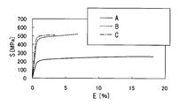
- FIG. 2 is a graph showing the relationship between tensile strength and elongation.
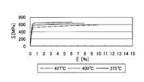
- FIG. 3 is a graph showing the tensile strength and the elongation percentage that change with the temperature of the aging treatment.
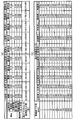
- FIG. 4A and FIG. 4B are tables showing the configurations of the insulated wires according to Examples and Comparative Examples used in the bending resistance test, and the experimental results.
- FIG. 1 is a schematic diagram illustrating an example of an insulated wire according to an embodiment of the present invention.
- the insulated wire 1 according to the present embodiment is obtained by coating an insulating insulating member 12 on a stranded conductor 11 as shown in FIG.
- the stranded wire conductor 11 is formed by twisting a plurality of conductive metal wires 11a (19 in the example shown in FIG. 1), and has a cross-sectional area of, for example, 0.08 sq (AWG28).
- the metal conductor wire 11a is made of a copper alloy, and specifically, Cu—Cr, Cu—Cr—Zr, Cu—Cr—Zn, Cu—Co—P, Cu— Manufactured from precipitation-strengthened copper alloys such as Ni-P and Cu-Fe-P.
- the stranded wire conductor 11 may be configured without twisting only one metal conductor strand 11a, or is not limited to one obtained by twisting 19 metal conductor strands 11a, for example, 30 strands.
- the metal conductor strands 11a may be twisted to have a cross-sectional area of 0.13 sq (AWG26), or another number of metal conductor strands 11a may be twisted together.
- the insulating member 12 is a polyvinyl chloride resin composition (or polyolefin resin composition) in the example shown in FIG. 1, it is not particularly limited thereto.
- the mixing ratio of each metal is as follows. That is, when the metal conductor wire 11a is a Cu—Cr—Zr copper alloy, Cr is 0.50 to 1.50 mass%, Zr is 0.05 to 0.15 mass%, Sn Is 0.10 to 0.20 mass%, and the balance is Cu. Further, when the stranded conductor 11 is a Cu—Co—P based copper alloy, Co is 0.20 to 0.30 mass%, P is 0.07 to 0.12 mass%, and Ni is 0.02 to 0.05. Furthermore, Sn is 0.08 to 0.12% by mass, Zn is 0.01 to 0.04% by mass, and the balance is Cu.
- the tensile strength of the metal conductor 11 is high.
- a tensile strength of 500 MPa or more can be achieved, and the present invention can be applied to a high cycle region.
- FIG. 2 is a graph showing the relationship between tensile strength and elongation.
- the symbol S on the vertical axis indicates the tensile strength [MPa]
- the symbol E on the horizontal axis indicates the elongation [%].
- the tensile strength of the annealed copper indicated by the symbol A varies depending on the elongation rate, but is about 200 MPa.
- the tensile strength of the copper alloy used as an industrial robot cable indicated by the symbol C and the above-described precipitation strengthened copper alloy indicated by the symbol B varies depending on the elongation, There is a region where the strength is 500 MPa or more. Therefore, it can be said that the copper alloy used as an industrial robot cable and the above-described precipitation-strengthened copper alloy are applicable to a high cycle region.
- the elongation rate of the metal conductor 11 is high.
- an elongation rate of 6% or more can be achieved, which can be applied to a low cycle region.
- the copper alloy used as the industrial robot cable indicated by the symbol C has a maximum elongation of about 3%. For this reason, an elongation rate of 6% or more cannot be achieved, and it cannot be applied to a low cycle region.
- the metal conductor 11 can achieve an elongation of 6% or more and can be applied to a low cycle region.
- the tensile strength is obtained from the test force (N) measured by using a tensile tester specified in JIS-Z-2241 (metal material tensile test method), and the elongation rate is obtained using a similar extensometer. It is obtained from the length between the measured points.
- the metal conductor 11 uses a copper alloy having a tensile strength of 500 MPa or more and an elongation of 6% or more, and has a strand diameter of 0.12 mm or less.
- the metal conductor 11 preferably has an elongation of less than 15%.
- the tensile strength is desirably less than 650 MPa. This is because, in the case of an alloy based on copper, when the tensile strength is 650 MPa or more, the elongation rate of 6% can no longer be maintained.
- the diameter of the metal conductor wire 11a is desirably 0.05 mm or more. This is because if there is no diameter of at least 0.05 mm or more, wire drawing becomes difficult due to accumulation of wire drawing distortion. In order to make the diameter smaller than this, a solution treatment must be performed in the middle of the wire drawing process to release the accumulated strain, but it is not easy to solution a wire material of 1 mm or less.
- FIG. 3 is a graph showing the tensile strength and the elongation percentage that change with the temperature of the aging treatment.
- the symbol S on the vertical axis indicates the tensile strength [MPa]
- the symbol E on the horizontal axis indicates the elongation [%].
- the tensile strength of the copper alloy according to this embodiment is increased by lowering the temperature of the aging treatment.
- the copper alloy which concerns on this embodiment exists in the tendency for elongation rate to become small by reducing the temperature of an aging treatment. For this reason, a copper alloy can be manufactured so as to exhibit appropriate characteristics by changing the temperature of the aging treatment.
- FIG. 4A and FIG. 4B are tables showing the configurations of the insulated wires according to Examples and Comparative Examples used in the bending resistance test, and the experimental results.
- Example 1 the diameter of the metal conductor wire was 0.08 mm.
- the copper alloy a Cu—Co—P based copper alloy was used. Specifically, the Cu—Co—P based copper alloy has Co of 0.20 to 0.30 mass%, P of 0.07 to 0.12 mass%, and Ni of 0.02 to 0 mass%. .05. Furthermore, Sn is 0.08 to 0.12% by mass, Zn is 0.01 to 0.04% by mass, and the balance is Cu.
- Example 1 the number of metal conductor strands was 19, and the outer diameter of the conductor constituted by 19 stranded wires was 0.40 mm.
- PVC polyvinyl chloride
- the finished outer diameter of the insulating member was 0.88 mm.
- Example 2 the diameter of the metal conductor wire was 0.03 mm. Further, the same copper alloy as in Example 1 was used. Furthermore, in Example 2, the number of metal conductor strands was 61, and the outer diameter of the conductor constituted by 61 stranded wires was 0.39 mm. Furthermore, PVC (polyvinyl chloride) having a thickness of 0.24 mm was used as the insulating member in Example 2. The finished outer diameter of the insulating member was 0.87 mm.
- Example 3 the diameter of the metal conductor wire was 0.05 mm. Further, the same copper alloy as in Example 1 was used. Furthermore, in Example 3, the number of metal conductor strands was 37, and the outer diameter of the conductor constituted by 37 stranded wires was 0.45 mm. Furthermore, in Example 3, PVC (polyvinyl chloride) having a thickness of 0.24 mm was used as the insulating member. The finished outer diameter of the insulating member was 0.93 mm.
- Example 4 the diameter of the metal conductor wire was 0.10 mm. Further, the same copper alloy as in Example 1 was used. Furthermore, in Example 4, the number of metal conductor strands was 19, and the outer diameter of the conductor composed of 19 stranded wires was 0.50 mm. In Example 4, PVC (polyvinyl chloride) having a thickness of 0.24 mm was used as the insulating member. The finished outer diameter of the insulating member was 0.98 mm.
- Example 5 the diameter of the metal conductor wire was 0.12 mm. Further, the same copper alloy as in Example 1 was used. Furthermore, in Example 5, the number of the metal conductor strands was 7, and the outer diameter of the conductor constituted by the seven stranded wires was 0.36 mm. Furthermore, in Example 5, PVC (polyvinyl chloride) having a thickness of 0.24 mm was used as the insulating member. The finished outer diameter of the insulating member was 0.84 mm.
- Comparative Example 1 the diameter of the metal conductor wire was 0.03 mm, and soft copper was used as the material. Furthermore, in Comparative Example 1, the number of metal conductor strands was 61, and the outer diameter of the conductor constituted by 61 stranded wires was 0.39 mm. Furthermore, in Comparative Example 1, PVC (polyvinyl chloride) having a thickness of 0.24 mm was used as the insulating member. The finished outer diameter of the insulating member was 0.87 mm.
- the diameter of the metal conductor wire was 0.05 mm, and soft copper was used as the material. Furthermore, in Comparative Example 2, the number of metal conductor strands was 37, and the outer diameter of the conductor constituted by 37 stranded wires was 0.45 mm. Furthermore, in Comparative Example 2, PVC (polyvinyl chloride) having a thickness of 0.24 mm was used as the insulating member. The finished outer diameter of the insulating member was 0.93 mm.
- Comparative Example 3 the diameter of the metal conductor wire was 0.08 mm, and soft copper was used as the material. Further, in Comparative Example 3, the number of metal conductor strands was 19, and the outer diameter of the conductor constituted by 19 stranded wires was 0.40 mm. Furthermore, in Comparative Example 3, PVC (polyvinyl chloride) having a thickness of 0.24 mm was used as the insulating member. The finished outer diameter of the insulating member was 0.88 mm.
- Comparative Example 4 the diameter of the metal conductor wire was 0.16 mm, and the same copper alloy as in Example 1 was used as the material. Further, in Comparative Example 4, the number of the metal conductor strands was 7, and the outer diameter of the conductor constituted by the seven stranded wires was 0.48 mm. Furthermore, in Comparative Example 4, PVC (polyvinyl chloride) having a thickness of 0.20 mm was used as the insulating member. The finished outer diameter of the insulating member was 0.88 mm.
- Comparative Example 5 the diameter of the metal conductor wire was 0.20 mm, and the same copper alloy as in Example 1 was used as the material. Further, in Comparative Example 5, the number of the metal conductor strands was 7, and the outer diameter of the conductor constituted by the seven stranded wires was 0.60 mm. Furthermore, in Comparative Example 5, PVC (polyvinyl chloride) having a thickness of 0.20 mm was used as the insulating member. The finished outer diameter of the insulating member was 1.00 mm.
- the results of the bending resistance test for Examples 1 to 5 and Comparative Examples 1 to 5 are as shown in FIG.
- the operation from the state in which the insulated wire of a predetermined length is straightened, bent along a mandrel having a bending radius of 20 mm in one direction, and returned straight again is repeated as one time.
- the number of bendings when the wire was broken was measured.
- the number of bendings of the insulated wire according to Example 1 reached 21562,300 times.
- the insulated wires according to Examples 2 to 5 had the number of bendings of 821,265,592, 145,152,405, 12,702,254, and 6,574,460, respectively.
- the number of bendings of the insulated wires according to Comparative Examples 1 to 5 was 3,248,908 times, 79,5137 times, 2,145,365 times, 1,862,672 times, and 686,637 times, respectively.
- Comparative Examples 3 to 5 the number of bendings was less than 5 million. For this reason, it turned out that it is not suitable for a high cycle area
- covered the insulating insulating member 12 on the stranded wire conductor 11 formed by twisting the electroconductive metal conductor strand 11a or the multiple metal conductor strand 11a.
- the metal conductor strand 11a is made of a copper alloy having a tensile strength of 500 MPa or more and an elongation of 6% or more, and a strand diameter is 0.12 mm or less.
- the insulated wire according to the present invention is useful in that an insulated wire that can be applied to both a high cycle region and a low cycle region can be provided.
Landscapes
- Chemical & Material Sciences (AREA)
- Engineering & Computer Science (AREA)
- Materials Engineering (AREA)
- Mechanical Engineering (AREA)
- Metallurgy (AREA)
- Organic Chemistry (AREA)
- Insulated Conductors (AREA)
Abstract
絶縁電線1は、複数本の金属導体素線11aが撚られてなる撚線導体11上に絶縁性の絶縁部材12を被覆したものであって、金属導体素線11aは、引張強さが500MPa以上、且つ、伸び率が6%以上である銅合金が用いられると共に、素線径が0.12mm以下である。
Description
本発明は、絶縁電線に関する。
従来、ロボットなどの機器は複雑な動きをする可動部を有している。このため、このような機器に用いられる電線についても可動部に適するものが必要となる。このような可動部では、例えば曲げ歪みを小さくするために曲げ半径を大きく設計するなどの工夫がなされている。また、このような可動部では、高サイクル疲労特性の優れた金属導体を用いた絶縁電線が使用される。ここで、曲げ歪みが小さく、高い屈曲疲労サイクルを要求される箇所(すなわち、高サイクル領域。)では金属導体の引張強さ(物性値[MPa])が高いことが有利であると知られている。
また、絶縁電線の高屈曲疲労特性の改善策として、金属導体に用いられる素線を細径化することが提案されている(特許文献1又は2参照。)。これらの文献によれば、金属導体素線を細径化することにより、金属導体に加わる歪みを小さくすることができ、且つ、金属導体の引張強度を高めることができる。すなわち、これらの技術では、同一の絶縁電線の曲げ半径においても、金属導体素線内部で生じる曲げ歪みを小さくして高サイクル領域に対応可能とした電線を提供できる。
しかし、特許文献1又は2に記載の絶縁電線では、高サイクル領域にしか適用することができず低サイクル領域には適さない可能性がある。例えば、ロボットなどの機器においては、使用する絶縁電線の屈曲疲労特性に合わせた曲げ半径の設計が必要となり、機器の屈曲耐久回数の要求値に応じて曲げ部を大きくしなければならない場合がある。また、組み付けの際に狭いスペースにおいて絶縁電線を小さい半径で曲げ、コネクタを繰り返し挿抜する可能性があるため、絶縁電線に加わる曲げ歪みが大きくなる箇所も存在する。このように絶縁電線を小さい曲げ半径で繰り返し屈曲する必要があり、絶縁電線に加わる曲げ歪みが大きくなる場合には、低サイクル領域に適した絶縁電線が必要である。このように絶縁電線に加わる曲げ歪みが大きくなる場合に、高サイクル領域のみに適した絶縁電線を使用すると、電線が曲げ歪みに耐えられず、導体破損などを引き起こしてしまう可能性がある。
本発明は上述した事情に鑑みてなされたものであり高サイクル領域及び低サイクル領域の双方に適用することが可能な絶縁電線を提供することを目的とする。
上記目的を達成するために、本発明に係る絶縁電線は、下記(1)を特徴としている。
(1) 導電性の金属導体素線、又は複数本の金属導体素線が撚られてなる撚線導体上に絶縁性の絶縁部材を被覆した絶縁電線であって、金属導体素線は、引張強さが500MPa以上、且つ、伸び率が6%以上である銅合金が用いられると共に、素線径が0.12mm以下である絶縁電線。
(1) 導電性の金属導体素線、又は複数本の金属導体素線が撚られてなる撚線導体上に絶縁性の絶縁部材を被覆した絶縁電線であって、金属導体素線は、引張強さが500MPa以上、且つ、伸び率が6%以上である銅合金が用いられると共に、素線径が0.12mm以下である絶縁電線。
この絶縁電線によれば、金属導体の引張強さが500MPa以上であり、且つ、伸び率が6%以上である銅合金が用いられると共に、素線径が0.12mm以下である。このため、例えばR=20mm以上の大きな屈曲に対して耐屈曲回数が500万回程度を実現することができ、曲げ歪みが小さく高い屈曲疲労サイクルを要求される高サイクル領域において適用することができる。また、金属導体の伸び率が6%以上であるため、曲げ歪みが大きい低サイクル領域においても適用することができる。従って、高サイクル領域及び低サイクル領域の双方について要求される屈曲耐久回数に適合することが可能な絶縁電線を提供することができる。
以下、本発明の好適な実施形態を図面に基づいて説明する。図1は、本発明の実施形態に係る絶縁電線の一例を示す概略図である。
本実施形態に係る絶縁電線1は、図1に示すように、撚線導体11上に絶縁性の絶縁部材12を被覆したものである。撚線導体11は、導電性の複数本(図1に示す例では、19本。)の金属導体素線11aが撚られて構成され、断面積が例えば0.08sq(AWG28)となっている。本実施形態において金属導体素線11aは、銅合金によって製造されており、具体的にCu-Cr系、Cu-Cr-Zr系、Cu-Cr-Zn系、Cu-Co-P系、Cu-Ni-P系及び、Cu-Fe-P系などの析出強化型の銅合金から製造されている。なお、撚線導体11は、1本の金属導体素線11aのみを撚り合わせずに構成されていてもよいし、19本の金属導体素線11aを撚り合わせたものに限らず例えば30本の金属導体素線11aを撚り合わせて断面積を0.13sq(AWG26)としたものであってもよいし、他の本数の金属導体素線11aを撚り合わせたものであってもよい。また、絶縁部材12は、図1に示す例ではポリ塩化ビニル系樹脂組成物(あるいはポリオレフィン系樹脂組成物。)であるが、特にこれに限られるものではない。
このような金属導体素線11aにおいて、各金属の配合率は以下のようになっている。すなわち、金属導体素線11aがCu-Cr-Zr系の銅合金である場合、Crが0.50~1.50質量%であり、Zrが0.05~0.15質量%であり、Snが0.10~0.20質量%であり、残部がCuである。また、撚線導体11がCu-Co-P系の銅合金である場合、Coが0.20~0.30質量%であり、Pが0.07~0.12質量%であり、Niが0.02~0.05である。さらに、Snが0.08~0.12質量%であり、Znが0.01~0.04質量%であり、残部がCuである。
ここで、本実施形態に係る絶縁電線1は、高サイクル領域及び低サイクル領域の双方において適用可能である。具体的に本実施形態に係る絶縁電線1は、曲げR=20mm以上の小さな曲げ歪みにおいて屈曲回数が500万回以上を達成すると共に(すなわち、高サイクル領域に適用可能。)、曲げR=0.5mmの大きな曲げ歪みにおいて屈曲回数が数十回以上達成するものである(すなわち、低サイクル領域に適用可能。)。以下、詳細に説明する。
まず、高サイクル領域に適用可能な絶縁電線を提供するにあたっては、金属導体11の引張強度が高いことが有利である。本実施形態では上記金属導体11を用いることにより、引張強度500MPa以上を達成することができ、高サイクル領域に適用可能である。
図2は、引張強度と伸び率との関係を示すグラフである。なお、図2において縦軸の符号Sは引張強度〔MPa〕を示し、横軸の符号Eは伸び率〔%〕を示している。
図2に示すように、符号Aにて示す軟銅の引張強度は伸び率によって異なるが、概ね200MPa強程度である。これに対して、符号Cにて示す産業用のロボットケーブルとして使用される銅合金、及び、符号Bにて示す上記した析出強化型の銅合金の引張強度については、伸び率によって異なるが、引張強度が500MPa以上となる領域が存在する。従って、産業用のロボットケーブルとして使用される銅合金、及び、上記した析出強化型の銅合金は、高サイクル領域に適用可能といえる。
また、低サイクル領域に適用可能な絶縁電線を提供するにあたっては、金属導体11の伸び率が高いことが有利である。本実施形態では上記金属導体11を用いることにより、伸び率6%以上を達成することができ、低サイクル領域に適用可能である。
図2に示すように、符号Cにて示す産業用のロボットケーブルとして使用される銅合金は、伸び率3%程度で最大である。このため、伸び率6%以上を達成できず、低サイクル領域に適用することができない。これに対して、上記金属導体11は、伸び率6%以上を達成でき、低サイクル領域に適用可能といえる。なお、引張強さは、JIS-Z-2241(金属材料引張試験方法)に規定される引張試験機を用いて測定した試験力(N)から求められ、伸び率は、同様の伸び計を用いて測定した標点間の長さから求められる。
なお、高サイクル領域では曲げR=20mm以上の小さな曲げ歪みにおいて高い屈曲性が要求される。このため、本実施形態においてはR=20mmの曲げにおいて高い屈曲性を満たすように金属導体素線11aの径を設定することが必要である。そして、本件発明者らが鋭意検討を重ねた結果、金属導体素線11aの径が小さくなるほど、歪みは小さくなる傾向にあることから、金属導体11に使用される銅合金がR=20mmの曲げにおいて高い屈曲性を満たすためには、素線径が0.12mm以下である必要があることを見出した。これにより、R=20mm以上の大きな屈曲に対して耐屈曲回数が500万回程度を実現することができる。
以上より、本実施形態に係る金属導体11は、引張強度が500MPa以上、且つ、伸び率が6%以上である銅合金が用いられると共に、素線径が0.12mm以下である。
なお、上記条件に加えて金属導体11は、伸び率は15%未満であることが望ましい。伸び率と引張強さとは相関があり、伸び率を変化させると引張強さも変化する。このような事情から、銅を基本とした導電率65%IACS(International Annealed Copper Standard)以上の析出強化型の合金の場合、伸び率が15%以上となると、もはや引張強さ500MPaを維持できない。さらに、引張強さは650MPa未満であることが望ましい。銅を基本とした合金の場合、引張強さが650MPa以上となると、もはや伸び率6%を維持できないからである。
さらに、金属導体素線11aの径は、0.05mm以上であることが望ましい。少なくとも0.05mm以上の径が無ければ、伸線加工歪みの蓄積により伸線加工が困難となるからである。これ以下の径にするには伸線加工の中途に溶体化処理を実施して、蓄積された歪みを開放しなければならないが、1mm以下の線材を溶体化処理するのは容易ではない。
なお、引張強度及び伸び率については、導体材料の時効処理の温度を変化させることにより、ある程度調整可能である。図3は、時効処理の温度によって変化する引張強度及び伸び率を示すグラフである。なお、図3において縦軸の符号Sは引張強度〔MPa〕を示し、横軸の符号Eは伸び率〔%〕を示している。
図3に示すように、時効処理の温度を低下させることにより、本実施形態に係る銅合金は引張強度が高くなる。これに対して、本実施形態に係る銅合金は、時効処理の温度を低下させることにより、伸び率が小さくなる傾向にある。このため、銅合金については時効処理の温度を変化させることで、適切な特性を示すように製造可能である。
次に、本実施形態に係る絶縁電線1の耐屈曲試験の実験結果について説明する。図4(a)及び図4(b)は、耐屈曲試験に用いられる実施例及び比較例に係る絶縁電線の構成、並びに実験結果を示す図表である。
図4(a)及び図4(b)に示すように、まず、実施例1において金属導体素線の径は0.08mmとした。また、銅合金としては、Cu-Co-P系の銅合金を使用した。具体的に、Cu-Co-P系の銅合金は、Coが0.20~0.30質量%であり、Pが0.07~0.12質量%であり、Niが0.02~0.05である。さらに、Snが0.08~0.12質量%であり、Znが0.01~0.04質量%であり、残部がCuである。
また、実施例1において金属導体素線の本数は19本であり、19本の撚線により構成される導体の外径は0.40mmであった。さらに、実施例1において絶縁部材には、厚さ0.24mmのPVC(polyvinyl chloride)を用いた。また、絶縁部材の仕上外径は0.88mmであった。
また、実施例2において金属導体素線の径は0.03mmとした。また、銅合金としては、実施例1と同じものを用いた。さらに、実施例2において金属導体素線の本数は61本であり、61本の撚線により構成される導体の外径は0.39mmであった。さらに、実施例2において絶縁部材には、厚さ0.24mmのPVC(polyvinyl chloride)を用いた。また、絶縁部材の仕上外径は0.87mmであった。
実施例3において金属導体素線の径は0.05mmとした。また、銅合金としては、実施例1と同じものを用いた。さらに、実施例3において金属導体素線の本数は37本であり、37本の撚線により構成される導体の外径は0.45mmであった。さらに、実施例3において絶縁部材には、厚さ0.24mmのPVC(polyvinyl chloride)を用いた。また、絶縁部材の仕上外径は0.93mmであった。
実施例4において金属導体素線の径は0.10mmとした。また、銅合金としては、実施例1と同じものを用いた。さらに、実施例4において金属導体素線の本数は19本であり、19本の撚線により構成される導体の外径は0.50mmであった。さらに、実施例4において絶縁部材には、厚さ0.24mmのPVC(polyvinyl chloride)を用いた。また、絶縁部材の仕上外径は0.98mmであった。
実施例5において金属導体素線の径は0.12mmとした。また、銅合金としては、実施例1と同じものを用いた。さらに、実施例5において金属導体素線の本数は7本であり、7本の撚線により構成される導体の外径は0.36mmであった。さらに、実施例5において絶縁部材には、厚さ0.24mmのPVC(polyvinyl chloride)を用いた。また、絶縁部材の仕上外径は0.84mmであった。
また、比較例1において金属導体素線の径は0.03mmとし、材料に軟銅を用いた。さらに、比較例1において金属導体素線の本数は61本であり、61本の撚線により構成される導体の外径は0.39mmであった。さらに、比較例1において絶縁部材には、厚さ0.24mmのPVC(polyvinyl chloride)を用いた。また、絶縁部材の仕上外径は0.87mmであった。
比較例2において金属導体素線の径は0.05mmとし、材料に軟銅を用いた。さらに、比較例2において金属導体素線の本数は37本であり、37本の撚線により構成される導体の外径は0.45mmであった。さらに、比較例2において絶縁部材には、厚さ0.24mmのPVC(polyvinyl chloride)を用いた。また、絶縁部材の仕上外径は0.93mmであった。
比較例3において金属導体素線の径は0.08mmとし、材料に軟銅を用いた。さらに、比較例3において金属導体素線の本数は19本であり、19本の撚線により構成される導体の外径は0.40mmであった。さらに、比較例3において絶縁部材には、厚さ0.24mmのPVC(polyvinyl chloride)を用いた。また、絶縁部材の仕上外径は0.88mmであった。
比較例4において金属導体素線の径は0.16mmとし、材料には実施例1と同じ銅合金を用いた。さらに、比較例4において金属導体素線の本数は7本であり、7本の撚線により構成される導体の外径は0.48mmであった。さらに、比較例4において絶縁部材には、厚さ0.20mmのPVC(polyvinyl chloride)を用いた。また、絶縁部材の仕上外径は0.88mmであった。
比較例5において金属導体素線の径は0.20mmとし、材料には実施例1と同じ銅合金を用いた。さらに、比較例5において金属導体素線の本数は7本であり、7本の撚線により構成される導体の外径は0.60mmであった。さらに、比較例5において絶縁部材には、厚さ0.20mmのPVC(polyvinyl chloride)を用いた。また、絶縁部材の仕上外径は1.00mmであった。
以上、実施例1~5及び比較例1~5について、耐屈曲試験を行った結果、図4に示すようになった。なお、耐屈曲試験では、所定長の絶縁電線を真っ直ぐに伸ばした状態から、一方向へ曲げ半径20mmを有するマンドレルに沿わせて曲げ、再び真っ直ぐに戻す動作までを1回として繰り返し、金属導体素線が断線したときの曲げ回数を測定した。
図4(a)及び図4(b)に示すように、実施例1に係る絶縁電線は、曲げ回数が2156万2300回に達した。また、実施例2~5に係る絶縁電線は、それぞれ曲げ回数が8億2162万5692回、1億4051万2405回、1270万2254回、657万4460回となった。
これに対して、比較例1~5に係る絶縁電線は、それぞれ曲げ回数が3248万908回、795万137回、214万5365回、186万2672回、68万637回となった。
以上のように、実施例1~5については、いずれも曲げ回数が500万回を超えており、高サイクル領域に適することが分かった。さらに、実施例に係る絶縁電線の導体は、伸び率6%以上であるため、低サイクル領域にも適するものである。
一方、比較例3~5については、いずれも曲げ回数が500万回を下回った。このため、高サイクル領域に適しないことが分かった。さらに、比較例1,2については、曲げ回数が500万回を超えているが、実験結果からすると、その素線径は0.05mm以下に限られることとなり、金属導体素線は極細線に限られてしまうという問題があることがわかった。また、同じ素線径において比較すると(比較例1と実施例2、比較例2と実施例3との比較)、曲げ回数は、実施例2,3に対してはるかに及ばないことがわかった。
このようにして、本実施形態に係る絶縁電線1は、金属導体11の引張強さが500MPa以上であり、且つ、伸び率が6%以上である銅合金が用いられると共に、素線径が0.12mm以下である。このため、例えばR=20mm以上の大きな屈曲に対して耐屈曲回数が500万回程度を実現することができ、曲げ歪みが小さく高い屈曲疲労サイクルを要求される高サイクル領域において適用することができる。また、導体の伸び率が6%以上であるため、曲げ歪みが大きい低サイクル領域においても適用することができる。従って、高サイクル領域及び低サイクル領域の双方について要求される屈曲耐久回数に適合することが可能な絶縁電線1を提供することができる。
以上、実施形態に基づき本発明を説明したが、本発明は上記実施形態に限られるものではなく、本発明の趣旨を逸脱しない範囲で、変更を加えてもよい。
以下では、実施形態に係る絶縁電線について纏める。
(1)実施形態に係る絶縁電線1は、導電性の金属導体素線11a、又は複数本の金属導体素線11aが撚られてなる撚線導体11上に絶縁性の絶縁部材12を被覆した絶縁電線であって、前記金属導体素線11aは、引張強さが500MPa以上、且つ、伸び率が6%以上である銅合金が用いられると共に、素線径が0.12mm以下である。
(1)実施形態に係る絶縁電線1は、導電性の金属導体素線11a、又は複数本の金属導体素線11aが撚られてなる撚線導体11上に絶縁性の絶縁部材12を被覆した絶縁電線であって、前記金属導体素線11aは、引張強さが500MPa以上、且つ、伸び率が6%以上である銅合金が用いられると共に、素線径が0.12mm以下である。
本出願は、2012年12月26日出願の日本特許出願(特願2012-283148)に基づくものであり、その内容はここに参照として取り込まれる。
本発明に係る絶縁電線によれば、高サイクル領域及び低サイクル領域の双方に適用することが可能な絶縁電線を提供できる点で有用である。
1…絶縁電線
11…金属導体
11a…金属導体素線
12…絶縁部材
11…金属導体
11a…金属導体素線
12…絶縁部材
Claims (1)
- 導電性の金属導体素線、又は複数本の金属導体素線が撚られてなる撚線導体上に絶縁性の絶縁部材を被覆した絶縁電線であって、
前記金属導体素線は、引張強さが500MPa以上、且つ、伸び率が6%以上である銅合金が用いられると共に、素線径が0.12mm以下である
絶縁電線。
Priority Applications (3)
| Application Number | Priority Date | Filing Date | Title |
|---|---|---|---|
| CN201380067864.9A CN104885164A (zh) | 2012-12-26 | 2013-12-13 | 绝缘电线 |
| EP13869601.8A EP2924696A4 (en) | 2012-12-26 | 2013-12-13 | ISOLATED WIRE |
| US14/751,440 US20150294758A1 (en) | 2012-12-26 | 2015-06-26 | Insulated Wire |
Applications Claiming Priority (2)
| Application Number | Priority Date | Filing Date | Title |
|---|---|---|---|
| JP2012-283148 | 2012-12-26 | ||
| JP2012283148A JP2014127345A (ja) | 2012-12-26 | 2012-12-26 | 絶縁電線 |
Related Child Applications (1)
| Application Number | Title | Priority Date | Filing Date |
|---|---|---|---|
| US14/751,440 Continuation US20150294758A1 (en) | 2012-12-26 | 2015-06-26 | Insulated Wire |
Publications (1)
| Publication Number | Publication Date |
|---|---|
| WO2014103750A1 true WO2014103750A1 (ja) | 2014-07-03 |
Family
ID=51020838
Family Applications (1)
| Application Number | Title | Priority Date | Filing Date |
|---|---|---|---|
| PCT/JP2013/083461 Ceased WO2014103750A1 (ja) | 2012-12-26 | 2013-12-13 | 絶縁電線 |
Country Status (5)
| Country | Link |
|---|---|
| US (1) | US20150294758A1 (ja) |
| EP (1) | EP2924696A4 (ja) |
| JP (1) | JP2014127345A (ja) |
| CN (1) | CN104885164A (ja) |
| WO (1) | WO2014103750A1 (ja) |
Families Citing this family (4)
| Publication number | Priority date | Publication date | Assignee | Title |
|---|---|---|---|---|
| JP6354275B2 (ja) * | 2014-04-14 | 2018-07-11 | 株式会社オートネットワーク技術研究所 | 銅合金素線、銅合金撚線および自動車用電線 |
| JP2017199457A (ja) * | 2016-04-25 | 2017-11-02 | 矢崎総業株式会社 | 高屈曲絶縁電線及びワイヤーハーネス |
| DE112019004174T5 (de) * | 2018-08-21 | 2021-08-05 | Autonetworks Technologies, Ltd. | Bedeckter elektrischer Draht, mit Anschluss ausgerüsteter elektrischer Draht, Kupferlegierungsdraht und Kupferlegierungs-Litze |
| JP7334629B2 (ja) * | 2020-01-21 | 2023-08-29 | 株式会社プロテリアル | 対撚りケーブル及び多心ケーブル |
Citations (4)
| Publication number | Priority date | Publication date | Assignee | Title |
|---|---|---|---|---|
| JP2001093341A (ja) | 1999-09-21 | 2001-04-06 | Hitachi Cable Ltd | 耐疲労絶縁電線 |
| JP2001295011A (ja) * | 2000-04-05 | 2001-10-26 | Hitachi Cable Ltd | 耐屈曲銅合金線及びそれを用いたケーブル |
| JP2010018848A (ja) | 2008-07-10 | 2010-01-28 | Hitachi Cable Ltd | 銅合金線およびその製造方法、銅合金撚線およびその製造方法、これらを用いた絶縁電線、同軸ケーブル並びに多芯ケーブル |
| WO2010084989A1 (ja) * | 2009-01-26 | 2010-07-29 | 古河電気工業株式会社 | 配線用電線導体、配線用電線導体の製造方法、配線用電線および銅合金素線 |
Family Cites Families (6)
| Publication number | Priority date | Publication date | Assignee | Title |
|---|---|---|---|---|
| JPH05302155A (ja) * | 1992-04-27 | 1993-11-16 | Furukawa Electric Co Ltd:The | 高強度高導電性銅合金線材の製造方法 |
| JP5520438B2 (ja) * | 2006-09-05 | 2014-06-11 | 古河電気工業株式会社 | 線材の製造方法および線材の製造装置 |
| JP2008266787A (ja) * | 2007-03-28 | 2008-11-06 | Furukawa Electric Co Ltd:The | 銅合金材およびその製造方法 |
| CA2706199C (en) * | 2008-03-28 | 2014-06-10 | Mitsubishi Shindoh Co., Ltd. | High strength and high conductivity copper alloy pipe, rod, or wire |
| JP5380117B2 (ja) * | 2009-03-11 | 2014-01-08 | 三菱伸銅株式会社 | 電線導体の製造方法、電線導体、絶縁電線及びワイヤーハーネス |
| JP6002360B2 (ja) * | 2010-07-21 | 2016-10-05 | 矢崎総業株式会社 | 端子付電線 |
-
2012
- 2012-12-26 JP JP2012283148A patent/JP2014127345A/ja not_active Abandoned
-
2013
- 2013-12-13 WO PCT/JP2013/083461 patent/WO2014103750A1/ja not_active Ceased
- 2013-12-13 EP EP13869601.8A patent/EP2924696A4/en not_active Ceased
- 2013-12-13 CN CN201380067864.9A patent/CN104885164A/zh active Pending
-
2015
- 2015-06-26 US US14/751,440 patent/US20150294758A1/en not_active Abandoned
Patent Citations (4)
| Publication number | Priority date | Publication date | Assignee | Title |
|---|---|---|---|---|
| JP2001093341A (ja) | 1999-09-21 | 2001-04-06 | Hitachi Cable Ltd | 耐疲労絶縁電線 |
| JP2001295011A (ja) * | 2000-04-05 | 2001-10-26 | Hitachi Cable Ltd | 耐屈曲銅合金線及びそれを用いたケーブル |
| JP2010018848A (ja) | 2008-07-10 | 2010-01-28 | Hitachi Cable Ltd | 銅合金線およびその製造方法、銅合金撚線およびその製造方法、これらを用いた絶縁電線、同軸ケーブル並びに多芯ケーブル |
| WO2010084989A1 (ja) * | 2009-01-26 | 2010-07-29 | 古河電気工業株式会社 | 配線用電線導体、配線用電線導体の製造方法、配線用電線および銅合金素線 |
Non-Patent Citations (1)
| Title |
|---|
| See also references of EP2924696A4 * |
Also Published As
| Publication number | Publication date |
|---|---|
| CN104885164A (zh) | 2015-09-02 |
| EP2924696A4 (en) | 2016-06-29 |
| EP2924696A1 (en) | 2015-09-30 |
| JP2014127345A (ja) | 2014-07-07 |
| US20150294758A1 (en) | 2015-10-15 |
Similar Documents
| Publication | Publication Date | Title |
|---|---|---|
| JP6002360B2 (ja) | 端子付電線 | |
| JP5836554B2 (ja) | 電源用ケーブル | |
| JP2015086452A (ja) | 銅合金線、銅合金撚線、被覆電線、ワイヤーハーネス及び銅合金線の製造方法 | |
| JP6080336B2 (ja) | 電線・ケーブル | |
| JP4728603B2 (ja) | 自動車配線用アルミ導電線及び自動車配線用電線 | |
| US10242766B2 (en) | Highly bendable insulated electric wire and wire harness | |
| JP7265324B2 (ja) | 絶縁電線、ケーブル | |
| WO2014103750A1 (ja) | 絶縁電線 | |
| JP2019061957A (ja) | 同軸ケーブル | |
| WO2012111831A1 (ja) | 高屈曲絶縁電線 | |
| JP2018078007A (ja) | アルミツイスト電線及びワイヤーハーネス | |
| JP4413591B2 (ja) | 自動車ワイヤハーネス用アルミ導電線および自動車ワイヤハーネス用アルミ電線 | |
| JP4330003B2 (ja) | アルミ導電線 | |
| JP4330005B2 (ja) | アルミ導電線 | |
| CN107887053B (zh) | 镀敷铜线、镀敷绞线和绝缘电线以及镀敷铜线的制造方法 | |
| JP7424042B2 (ja) | 撚線導体、絶縁電線、及び撚線導体の製造方法 | |
| JP7389624B2 (ja) | ケーブル | |
| JP4913654B2 (ja) | 圧縮導体 | |
| US20170256337A1 (en) | Heat-resistant and oil-resistant insulated electric wire | |
| JP4728599B2 (ja) | 自動車配線用アルミ導電線及び自動車配線用電線 | |
| JP4667770B2 (ja) | 自動車配線用アルミ導電線および自動車配線用電線 | |
| JP6424925B2 (ja) | めっき銅線、めっき撚線及び絶縁電線並びにめっき銅線の製造方法 | |
| JP4986522B2 (ja) | 自動車電線用素線及び自動車用電線 | |
| JP7295817B2 (ja) | ワイヤーハーネス用導体撚線 | |
| JP2006004760A (ja) | アルミ導電線 |
Legal Events
| Date | Code | Title | Description |
|---|---|---|---|
| 121 | Ep: the epo has been informed by wipo that ep was designated in this application |
Ref document number: 13869601 Country of ref document: EP Kind code of ref document: A1 |
|
| WWE | Wipo information: entry into national phase |
Ref document number: 2013869601 Country of ref document: EP |
|
| NENP | Non-entry into the national phase |
Ref country code: DE |