WO2014103882A1 - 鉄道車両用ディスクブレーキ装置 - Google Patents
鉄道車両用ディスクブレーキ装置 Download PDFInfo
- Publication number
- WO2014103882A1 WO2014103882A1 PCT/JP2013/084112 JP2013084112W WO2014103882A1 WO 2014103882 A1 WO2014103882 A1 WO 2014103882A1 JP 2013084112 W JP2013084112 W JP 2013084112W WO 2014103882 A1 WO2014103882 A1 WO 2014103882A1
- Authority
- WO
- WIPO (PCT)
- Prior art keywords
- point side
- side arm
- brake device
- railway vehicle
- portions
- Prior art date
- Legal status (The legal status is an assumption and is not a legal conclusion. Google has not performed a legal analysis and makes no representation as to the accuracy of the status listed.)
- Ceased
Links
Images







Classifications
-
- F—MECHANICAL ENGINEERING; LIGHTING; HEATING; WEAPONS; BLASTING
- F16—ENGINEERING ELEMENTS AND UNITS; GENERAL MEASURES FOR PRODUCING AND MAINTAINING EFFECTIVE FUNCTIONING OF MACHINES OR INSTALLATIONS; THERMAL INSULATION IN GENERAL
- F16D—COUPLINGS FOR TRANSMITTING ROTATION; CLUTCHES; BRAKES
- F16D55/00—Brakes with substantially-radial braking surfaces pressed together in axial direction, e.g. disc brakes
- F16D55/02—Brakes with substantially-radial braking surfaces pressed together in axial direction, e.g. disc brakes with axially-movable discs or pads pressed against axially-located rotating members
- F16D55/22—Brakes with substantially-radial braking surfaces pressed together in axial direction, e.g. disc brakes with axially-movable discs or pads pressed against axially-located rotating members by clamping an axially-located rotating disc between movable braking members, e.g. movable brake discs or brake pads
- F16D55/224—Brakes with substantially-radial braking surfaces pressed together in axial direction, e.g. disc brakes with axially-movable discs or pads pressed against axially-located rotating members by clamping an axially-located rotating disc between movable braking members, e.g. movable brake discs or brake pads with a common actuating member for the braking members
- F16D55/2245—Brakes with substantially-radial braking surfaces pressed together in axial direction, e.g. disc brakes with axially-movable discs or pads pressed against axially-located rotating members by clamping an axially-located rotating disc between movable braking members, e.g. movable brake discs or brake pads with a common actuating member for the braking members in which the common actuating member acts on two levers carrying the braking members, e.g. tong-type brakes
-
- B—PERFORMING OPERATIONS; TRANSPORTING
- B61—RAILWAYS
- B61H—BRAKES OR OTHER RETARDING DEVICES SPECIALLY ADAPTED FOR RAIL VEHICLES; ARRANGEMENT OR DISPOSITION THEREOF IN RAIL VEHICLES
- B61H5/00—Applications or arrangements of brakes with substantially radial braking surfaces pressed together in axial direction, e.g. disc brakes
-
- F—MECHANICAL ENGINEERING; LIGHTING; HEATING; WEAPONS; BLASTING
- F16—ENGINEERING ELEMENTS AND UNITS; GENERAL MEASURES FOR PRODUCING AND MAINTAINING EFFECTIVE FUNCTIONING OF MACHINES OR INSTALLATIONS; THERMAL INSULATION IN GENERAL
- F16D—COUPLINGS FOR TRANSMITTING ROTATION; CLUTCHES; BRAKES
- F16D65/00—Parts or details
- F16D65/14—Actuating mechanisms for brakes; Means for initiating operation at a predetermined position
- F16D65/16—Actuating mechanisms for brakes; Means for initiating operation at a predetermined position arranged in or on the brake
- F16D65/18—Actuating mechanisms for brakes; Means for initiating operation at a predetermined position arranged in or on the brake adapted for drawing members together, e.g. for disc brakes
-
- F—MECHANICAL ENGINEERING; LIGHTING; HEATING; WEAPONS; BLASTING
- F16—ENGINEERING ELEMENTS AND UNITS; GENERAL MEASURES FOR PRODUCING AND MAINTAINING EFFECTIVE FUNCTIONING OF MACHINES OR INSTALLATIONS; THERMAL INSULATION IN GENERAL
- F16D—COUPLINGS FOR TRANSMITTING ROTATION; CLUTCHES; BRAKES
- F16D2121/00—Type of actuator operation force
- F16D2121/02—Fluid pressure
- F16D2121/04—Fluid pressure acting on a piston-type actuator, e.g. for liquid pressure
-
- F—MECHANICAL ENGINEERING; LIGHTING; HEATING; WEAPONS; BLASTING
- F16—ENGINEERING ELEMENTS AND UNITS; GENERAL MEASURES FOR PRODUCING AND MAINTAINING EFFECTIVE FUNCTIONING OF MACHINES OR INSTALLATIONS; THERMAL INSULATION IN GENERAL
- F16D—COUPLINGS FOR TRANSMITTING ROTATION; CLUTCHES; BRAKES
- F16D2121/00—Type of actuator operation force
- F16D2121/02—Fluid pressure
- F16D2121/08—Fluid pressure acting on a membrane-type actuator, e.g. for gas pressure
-
- F—MECHANICAL ENGINEERING; LIGHTING; HEATING; WEAPONS; BLASTING
- F16—ENGINEERING ELEMENTS AND UNITS; GENERAL MEASURES FOR PRODUCING AND MAINTAINING EFFECTIVE FUNCTIONING OF MACHINES OR INSTALLATIONS; THERMAL INSULATION IN GENERAL
- F16D—COUPLINGS FOR TRANSMITTING ROTATION; CLUTCHES; BRAKES
- F16D2125/00—Components of actuators
- F16D2125/18—Mechanical mechanisms
- F16D2125/58—Mechanical mechanisms transmitting linear movement
- F16D2125/64—Levers
Definitions
- the present invention relates to a disk brake device for a railway vehicle.
- Patent Literature 1 As a railway vehicle disc brake device, a configuration using the lever principle is known (for example, see Patent Document 1).
- the disc brake device described in Patent Literature 1 includes a pair of brake pad receivers, a pair of arms, and a drive mechanism.
- the pair of restrictor receivers are arranged so as to sandwich a disk that rotates integrally with the wheels, and hold a pair of pads.
- the pair of restrictor receivers are attached to the pair of arms.
- Each arm can swing about a fulcrum shaft extending in a substantially vertical direction.
- Each arm is connected to a drive mechanism.
- the drive mechanism drives each arm so that each arm swings around the fulcrum axis. With this configuration, each arm is rotated. As a result, the pads held by the arms via the brake catcher contact the disk and apply a braking force to the disk.
- the arm receives a large load from the drive mechanism and a large reaction force from the disk when braking the railway vehicle. For this reason, the arm is formed in a shape having sufficient strength.
- the arm has a large shape corresponding to a large disk for a railway vehicle, and the cross-sectional shape of the arm (the shape in a cross section perpendicular to the extending direction of the arm) is a square shape or an elliptical shape. Etc.
- the arm is formed to have sufficient strength.
- the arm becomes thicker than necessary. That is, the arm becomes excessively heavy.
- the present invention has been made in view of the above circumstances, and an object of the present invention is to provide a railway vehicle disk brake device capable of ensuring sufficient strength and achieving weight reduction.
- a railway vehicle disc brake device includes a caliper lever for supporting a pad disposed opposite to a disc, a direction in which the pad approaches the disc, and A fulcrum shaft that swingably supports the caliper so that the caliper can swing in a direction away from the disk; and a drive device that drives the caliper around the fulcrum shaft.
- the arm portion has a first portion and a second portion that extend so as to cross each other in a cross section orthogonal to a direction in which the arm portion extends.
- the shape of the arm portion is, for example, a shape in which a part of the polygonal shape or a part of the round shape is omitted.
- an arm part can be made lighter. That is, the weight reduction of the railcar disc brake device can be achieved through the weight reduction of the caliper.
- the arm portion has a shape having sufficient bending rigidity. Thereby, the strength of the arm portion that receives a large load from the driving device and a large reaction force from the disk can be sufficiently ensured.
- an angle formed by a direction in which the first portion extends and a vertical direction is an angle between the direction in which the second portion extends and the vertical direction. Is smaller than the angle formed by
- the bending rigidity of the arm portion can be sufficiently ensured by the cooperation of the first portion extending at an angle relatively close to the vertical and the second portion extending at an angle relatively close to the horizontal.
- the arm portion is formed in an L shape.
- the arm portion can be lightened and sufficient rigidity can be secured with a simple configuration.
- the arm portion is disposed so as to have an inner surface facing the driving device and an outer surface disposed in a pair with the inner surface, and the arm portion includes the driving device and the fulcrum.
- a force point side arm portion extending between the shaft and a working point side arm portion extending from the fulcrum shaft side toward the pad side.
- the first portion is the outer portion. It arrange
- a space defined by the first member and the second member can be secured on the inner surface side of the power point side arm portion.
- a member such as a driving device arranged adjacent to the force point side arm portion can be arranged. Accordingly, it is possible to prevent interference (unintentional contact) between the force point side arm portion and the driving device or the like.
- the force point side arm portion does not need to have a detour shape for avoiding this interference, the force point side arm portion can be reduced in size. In particular, the force point side arm portion can be shortened in the longitudinal direction.
- the arm portion is disposed so as to have an inner surface facing the driving device and an outer surface disposed in a pair with the inner surface, and the arm portion includes the driving device and the fulcrum.
- a force point side arm portion extending between the shaft and an action point side arm portion extending from the fulcrum shaft side toward the pad side.
- the first portion is the It arrange
- the said 2nd part is arrange
- the action point side arm portion is bent and deformed in an arch shape by receiving a reaction force from the disk during braking of the vehicle.
- tensile stress is generated on the inner surface side of the action point side arm portion
- compressive stress is generated on the outer surface side of the action point side arm portion.
- the member has an allowable tensile stress smaller than the allowable compressive stress. Therefore, by disposing the first portion on the inner surface side where the tensile stress is generated when braking the vehicle, the volume of the portion that receives the tensile stress can be further increased. Thereby, the peak of the tensile stress of an action point side arm part can be reduced. As a result, the strength of the caliper can be increased through a reduction in the load on the action point side arm.
- the total length of the action point side arm is set smaller than the total length of the force point side arm portion.
- the total length of the action point side arm portion is short, further miniaturization of the railway vehicle disc brake device can be achieved. Further, since the total length (arm length) of the action point side arm portion is short, the stress of the action point side arm portion when the action point side arm portion is bent by the reaction force from the disk during braking of the vehicle is large. It is easy to become.
- the first portion is disposed on the inner surface side of the action point side arm portion. Thereby, the tensile stress on the inner surface side of the action point side arm portion can be dispersed. Therefore, the peak of the tensile stress generated in the action point side arm portion can be set to a sufficiently low value.
- a pair of upper and lower power point side arm portions are provided, and the caliper further has a connecting portion for connecting the first portions of the respective power point side arm portions.
- the pair of upper and lower force point side arm portions are integrally coupled via the connecting portion.
- strength of a pair of power point side arm part can be improved significantly. Therefore, the strength of the caliper can be increased by improving the strength of the pair of power point side arm portions.
- the connection part is extended between the 1st parts of a pair of power point side arm parts, the connection part of a connection part and a power point side arm part can be made into a smooth shape. Therefore, stress concentration at the connection portion between the connecting portion and the power point side arm portion can be reduced.
- the vehicular disc brake device further includes a lever support member that supports the caliper lever through the fulcrum shaft, and the lever support member is a predetermined line-up of the caliper lever and the drive device.
- a pair of upper and lower horizontal portions extending in the arrangement direction, a pair of the horizontal portions extending in a direction in which the pair of horizontal portions face each other, and a pair of the horizontal portions connected to each other, and the pair of the horizontal portions and the vertical shapes And a reinforcing rib connected to the portion.
- the shape of the lever support member can be made to be a shape close to a shape combining plate members rather than a block shape. Thereby, the lever support member can be further reduced in weight. Further, since the reinforcing rib is provided, the strength of the lever support member can be sufficiently ensured.
- the vertical portion is configured to be opposed to the disk, and the reinforcing rib extends from the vertical portion toward the driving device.
- the vertical portion is arranged so as to be close to the disk. Therefore, in the lever support member, the reaction force from the disk can be reliably received by the vertical portion.
- the vehicle disc brake device further includes a suspension shaft for suspending the lever support member so as to be swingable from a chassis, and the suspension shaft is disposed closer to the drive device.
- a small-diameter portion, and a large-diameter portion configured to be disposed closer to the pad and having a diameter larger than the diameter of the small-diameter portion.
- the large-diameter portion of the suspension shaft receives a large reaction force from the disk when the vehicle is braked. Therefore, the strength of the suspension shaft can be sufficiently ensured by setting the diameter of the large diameter portion large. Further, the reaction force received by the small diameter portion from the disk during braking of the vehicle is relatively small. Therefore, it is possible to reduce the weight of the suspension shaft by reducing the diameter of the small-diameter portion that does not receive a very large load on the suspension shaft.
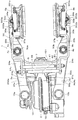
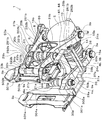
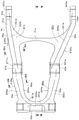
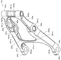
- FIG. 1 is a side view of a railway vehicle disc brake device according to an embodiment of the present invention. It is a top view of the disc brake device for rail vehicles. It is a bottom view of the disk brake device for rail vehicles. It is the perspective view which looked down at the disc brake device for rail vehicles. It is the perspective view which looked up at the disc brake device for rail vehicles. It is a perspective view of a caliper, and shows a state in which the inner surface of the caliper is viewed. It is a side view of a caliper, and shows a state where the inner side of the caliper is viewed.
- FIG. 8 is a cross-sectional view taken along the line VIII-VIII in FIG. 7 and shows a state where the caliper is looked up.
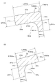
- FIG. 7 is a cross-sectional view taken along line IXA-IXA in FIG. 7, and (B) is a cross-sectional view taken along line IXB-IXB in FIG.
- It is a perspective view of a caliper, and shows a state where the outer surface of the caliper is viewed.
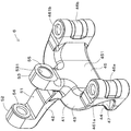
- It is a perspective view of a lever support member, and has shown the state which looked down at the lever support member.
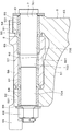
- FIG. 3 is a cross-sectional view taken along line XIII-XIII in FIG. It is a typical top view of the principal part for demonstrating operation
- FIG. 1 is a side view of a railway vehicle disc brake device 1 according to an embodiment of the present invention.
- FIG. 1 shows a state in which a vehicle disc brake device 1 is installed on a chassis 100.
- FIG. 2 is a plan view of the railway vehicle disc brake device 1.
- FIG. 3 is a bottom view of the railway vehicle disc brake device 1.
- members other than the railway vehicle disc brake device 1 are indicated by two-dot chain lines which are imaginary lines.
- FIG. 4 is a perspective view of the railway vehicle disc brake device 1 looking down.
- FIG. 5 is a perspective view of the railway vehicle disc brake device 1 looking up.
- a railway vehicle disc brake device 1 (hereinafter, also simply referred to as a brake device 1) is provided in a railway vehicle.
- the brake device 1 is installed in a lower part of a carriage 100 of a railway vehicle (hereinafter also simply referred to as a vehicle).
- the vehicle disc brake device 1 is adjacent to a disc 101 disposed at the lower part of the carriage 100.
- the disk 101 is a disk-shaped member and rotates together with the wheels when the vehicle is traveling.
- the brake device 1 applies a frictional force to the disc 101 by sandwiching the disc 101, thereby applying a braking force to the disc 101, and as a result, the vehicle is decelerated.
- the brake device 1 includes a cylinder device (drive device) 2, a pair of caliper levers 3 a and 3 b, fulcrum shaft members 4 a and 4 b, a pair of pad holders 5 a and 5 b, a lever support member 6, and a suspension shaft member 7. And a fixing bracket 8.
- the left-right direction is a direction in which the calipers 3a and 3b face each other.
- the front-rear direction is a direction in which the calipers 3a and 3b extend.
- the cylinder device 2 is provided to swing the calipers 3 a and 3 b around the fulcrum shafts 9 a and 9 b of the fulcrum shaft members 4 a and 4 b extending vertically.
- the fulcrum shaft members 4a and 4b are screw members.
- the fulcrum shafts 9a and 9b are round shafts having a male screw formed at the tip.
- the cylinder device 2 uses a fluid such as air or oil as a working fluid.
- the cylinder device 2 is disposed so as to face the disk 101 in the front-rear direction.
- the cylinder device 2 is arranged so as to be sandwiched between a pair of calipers 3a and 3b.
- the cylinder device 2 includes a cylinder housing 10, a rod member 11, a coupling 12, a column member 13, and a boot member 14.
- the cylinder housing 10 is formed in a hollow shape. An upper end portion and a lower end portion of the cylinder housing 10 are rotatably supported by the caliper lever 3b via screw members 15b and 15b. The cylinder housing 10 supports the rod member 11.
- the rod member 11 moves in the left-right direction as the fluid moves in a cylinder chamber (not shown) in the cylinder housing 10.
- the tip of the rod member 11 is coupled to the column member 13 via the coupling 12.
- the column member 13 is a member extending up and down.
- the column member 13 is configured to move in the left-right direction integrally with the rod member 11 via the coupling 12.
- the upper end portion and the lower end portion of the column member 13 are rotatably supported by the caliper lever 3a via screw members 15a and 15a.
- a boot member 14 is disposed between the column member 13 and the cylinder housing 10.
- the boot member 14 is a stretchable member formed in a bellows shape and surrounds the rod member 11.
- Caliper levers 3a and 3b are arranged so as to sandwich the cylinder device 2.
- the pair of calipers 3a and 3b are provided to support the pair of pads 102a and 102b that are arranged to face each other with the disc 101 interposed therebetween.
- the calipers 3a and 3b can press the pads 102a and 102b against the corresponding side surfaces 101a and 101b of the disk 101 by swinging around the fulcrum shafts 9a and 9b of the corresponding fulcrum shaft members 4a and 4b.
- the calipers 3a and 3b are made of metal and are formed by casting, forging, sintering or other manufacturing methods.
- the calipers 3a and 3b are solid members, and no internal cavities other than the through holes are formed.
- the calipers 3a and 3b are arranged so as to sandwich the cylinder device 2 and are arranged so as to sandwich the disk 101.
- the calipers 3a and 3b extend from a position adjacent to the cylinder device 2 to a position adjacent to the disk 101 in the front-rear direction, and are elongated members in the front-rear direction.
- the caliper levers 3a and 3b are each formed in a substantially A shape in a side view (FIG. 1).
- FIG. 6 is a perspective view of the caliper 3a, showing a state in which the inner surface 21a of the caliper 3a is viewed.
- FIG. 7 is a side view of the caliper lever 3a and shows a state in which the inner surface 21a of the caliper lever 3a is viewed.
- FIG. 8 is a cross-sectional view taken along line VIII-VIII in FIG. 7 and shows a state where the caliper lever 3a is looked up.
- 9A is a cross-sectional view taken along line IXA-IXA in FIG. 7, and FIG. 9B is a cross-sectional view taken along line IXB-IXB in FIG.
- the caliper lever 3a is arranged in an inclined shape, and extends in the front-rear direction so as to be closer to the road surface as the position is farther from the disk 101.
- the degree of inclination of the caliper lever 3a with respect to the horizontal plane (road surface) is a slight amount of about several degrees, and in the following description, this inclination is substantially zero.
- the caliper lever 3a includes an inner surface 21a facing the cylinder device 2, an outer surface 22a that is arranged to face the outer side of the brake device 1 and makes a pair with the inner surface 21a, an upper surface 23a that faces upward, and a lower surface 24a that faces downward. ,have.
- the caliper lever 3a includes a pair of upper and lower force point side arm portions 25a and 26a, a pair of upper and lower fulcrum portions 27a and 28a, a pair of upper and lower action point side arm portions 29a and 30a, a first connecting portion 31a, and a second. And a connecting portion 32a.
- the force point side arm portions 25a and 26a and the action point side arm portions 29a and 30a are examples of the “arm portion” of the present invention.
- the force point side arm portions 25a and 26a are provided as portions extending between the cylinder device 2 and the fulcrum shaft member 4a.
- the force point side arm portion 25a is disposed above the force point side arm portion 26a.
- One end portions of the force point side arm portions 25a and 26a in the front-rear direction constitute one end portion of the caliper lever 3a in the front-rear direction.
- One end portions of the force point side arm portions 25a and 26a are formed in a flat rectangular plate shape, and through holes 253a and 263a extending in the vertical direction are formed.
- the aforementioned screw members 15a and 15a are inserted into the through holes 253a and 263a.
- the intermediate portion and the other end portion of the force point side arm portion 25a in the front-rear direction are formed in an inclined shape, and extend downward as they move away from one end portion of the force point side arm portion 25a.
- the intermediate portion and the other end portion of the force point side arm portion 26a in the longitudinal direction are formed in an inclined shape, and extend upward as they move away from one end portion of the force point side arm portion 26a.
- the angle (inclination angle) at which the intermediate portion and the other end portion of the force point side arm portion 26a are inclined with respect to the horizontal plane is larger than the inclination angles of the intermediate portion and the other end portion of the force point side arm portion 25a.
- the intermediate part and the other end of the force point side arm part 25a have a first part 251a and a second part 252a.
- the first portion 251a and the second portion 252a are formed in an L shape as a whole.
- the first portion 251a and the second portion 252a extend so as to cross each other, and in the present embodiment, extend perpendicular to each other.
- an angle ⁇ 251a (minor angle) formed by the direction in which the first portion 251a extends and the vertical direction is smaller than an angle ⁇ 252a (minor angle) formed by the direction in which the second portion 252a extends and the vertical direction ( ⁇ 251a ⁇ 252a).
- the angle ⁇ 251a refers to, for example, an angle formed between the outer surface 22a and the vertical direction in the first portion 251a.
- the angle ⁇ 252a refers to, for example, an angle formed between the upper surface 23a and the vertical direction in the second portion 252a.
- the first portion 251a extends at an angle close to vertical
- the second portion 252a extends at an angle close to horizontal.
- the first portion 251a may extend vertically, and the second portion 252a may extend horizontally.
- the thickness t251a of the first portion 251a is smaller than the thickness t252a of the second portion 252a (t251a ⁇ t252a).
- the length L251a of the first portion 251a is smaller than the length L252a of the second portion 252a (L251a ⁇ L252a).
- the connection portion between the first portion 251a and the second portion 252a has a smooth arc shape, and stress concentration is suppressed from occurring in the connection portion.
- the first portion 251a is disposed near the outer surface 22a of the caliper lever 3a and constitutes a part of the outer surface 22a.
- the second portion 252a is disposed closer to the inner side surface 21a of the caliper lever 3a and constitutes a part of the inner side surface 21a.
- a space S1a is formed by the first portion 251a and the second portion 252a.
- the space S1a is a space between the pair of calipers 3a and 3b, and a member such as the boot member 14 of the cylinder device 2 can be disposed therein.
- the intermediate portion and the other end portion of the force point side arm portion 26a are disposed below the first portion 251a and the second portion 252a having the above-described configuration.
- the intermediate portion and the other end portion of the power point side arm portion 26a have a first portion 261a and a second portion 262a.
- the intermediate portion and the other end portion of the power point side arm portion 26a have substantially the same configuration as the intermediate portion and the other end portion of the power point side arm portion 25a.
- the first portion 261a and the second portion 262a of the power point side arm portion 26a are formed in an L shape as a whole. ing.
- the first portion 261a and the second portion 262a extend so as to intersect with each other, and are orthogonal to each other in this embodiment.
- first and second portions 262a, 262a in the cross section orthogonal to the direction in which the power point side arm portion 26a extends is the same as the first and second portions 251a in the cross section P1 orthogonal to the direction in which the power point side arm portion 25a extends. , 252a and a generally symmetrical shape.
- the first portion 261a is disposed near the outer surface 22a of the caliper lever 3a and constitutes a part of the outer surface 22a.
- the second portion 262a is disposed closer to the inner side surface 21a of the caliper lever 3a and constitutes a part of the inner side surface 21a.
- a space S2a is formed by the first portion 261a and the second portion 262a.
- the space S2a is a space between the pair of calipers 3a and 3b, and a member such as the boot member 14 of the cylinder device 2 can be disposed.
- the force point side arm portions 25a and 26a having the above-described configuration are connected by a first connecting portion 31a.
- the first connecting portion 31a extends between the first portions 251a and 261a of the force point side arm portions 25a and 26a, and is continuous with both the first portions 251a and 261a.
- the first connecting portion 31a extends substantially parallel to the vertical direction, and has a constricted shape in a side view.
- the thickness (length in the left-right direction) of the first connecting portion 31a is set to be substantially constant.
- the 1st connection part 31a is smoothly following each 1st part 251a, 261a. Thereby, it is suppressed that stress concentration arises in the connection part of the 1st connection part 31a and the 1st part 251a, 261a corresponding.
- a pair of upper and lower fulcrum portions 27a and 28a are arranged so as to be aligned with the first connecting portion 31a in the front-rear direction.
- the fulcrum portions 27a and 28a are provided as portions connected to the fulcrum shaft member 4a.
- the fulcrum portions 27a and 28a are each formed in a block shape, and the fulcrum portion 27a is disposed above the fulcrum portion 28a.
- the fulcrum part 27a is formed in a shape that is smoothly continuous with the force point side arm part 25a and the action point side arm part 29a, and is less likely to cause stress concentration.
- the fulcrum part 28a is formed in a shape that is smoothly continuous with the force point side arm part 26a and the action point side arm part 30a, and is less likely to cause stress concentration.
- Through holes 271a and 281a extending in the vertical direction are formed in the fulcrum portions 27a and 28a.
- Cylindrical bushes are fitted in the through holes 271a and 281a, and the fulcrum portions 27a and 28a are connected to the fulcrum shaft member 4a via the corresponding bushes.
- the fulcrum portions 27a and 28a are continuous with a pair of upper and lower action point side arm portions 29a and 30a.
- FIG. 10 is a perspective view of the caliper lever 3a, showing a state in which the outer surface 22a of the caliper lever 3a is viewed.
- the action point side arm portions 29a and 30a are provided as portions extending from the fulcrum shaft member 4a side toward the pad 102a (pad holder 5a) side.
- the action point side arm portion 29a is disposed above the action point side arm portion 30a.
- One end portions of the action point side arm portions 29a and 30a are continuous with the corresponding fulcrum portions 27a and 28a.
- the action point side arm portion 29a is formed in an inclined shape, and extends downward from one end portion of the action point side arm portion 29a to the second connecting portion 32a.
- the action point side arm portion 30a is formed in an inclined shape, and extends upward as it proceeds from one end of the action point side arm portion 30a to the second connecting portion 32a.
- the action point side arm portion 29a and the action point side arm portion 30a are formed in a vertically symmetrical shape.
- the angle ⁇ 29a at which the action point side arm portion 29a is inclined with respect to the horizontal plane is substantially the same as the angle ⁇ 25a at which the intermediate portion and the other end of the force point side arm portion 25a are inclined with respect to the horizontal plane. is there.
- This angle ⁇ 29a is smaller than the angle ⁇ 26a at which the intermediate portion and the other end of the force point side arm portion 26a are inclined with respect to the horizontal plane ( ⁇ 29a ⁇ 26a).
- the angle ⁇ 29a is an angle formed by the upper surface 23a and the horizontal plane in the action point side arm portion 29a.
- the angle ⁇ 25a is an angle formed by the upper surface 23a and the horizontal plane in the force point side arm portion 25a.
- the angle ⁇ 26a is an angle formed between the lower surface 24a of the force point side arm portion 26a and the horizontal plane.
- the action point side arm portion 29a has a first portion 291a and a second portion 292a.
- the first portion 291a and the second portion 292a are formed in an L shape as a whole.
- the first portion 291a and the second portion 292a extend so as to cross each other, and are orthogonal to each other in this embodiment.
- an angle ⁇ 291a (minor angle) formed by the direction in which the first portion 291a extends and the vertical direction is smaller than an angle ⁇ 292a (minor angle) formed by the direction in which the second portion 292a extends and the vertical direction ( ⁇ 291a ⁇ 292a).
- the angle ⁇ 291a refers to, for example, an angle formed between the inner side surface 21a and the vertical direction in the first portion 291a.
- the angle ⁇ 292a refers to, for example, an angle formed between the upper surface 23a and the vertical direction in the second portion 292a.
- the first portion 291a extends at an angle close to vertical
- the second portion 292a extends at an angle close to horizontal.
- the first portion 291a may extend vertically, and the second portion 292a may extend horizontally.
- the thickness t291a of the first portion 291a is smaller than the thickness t292a of the second portion 292a (t291a ⁇ t292a).
- the length L291a of the first portion 291a is smaller than the length L292a of the second portion 292a (L291a ⁇ L292a).
- the connection portion between the first portion 291a and the second portion 292a has a smooth arc shape, and stress concentration is suppressed from occurring in the connection portion.
- the first portion 291a is disposed near the inner side surface 21a of the caliper lever 3a and constitutes a part of the inner side surface 21a.
- the second portion 292a is disposed closer to the outer surface 22a of the caliper lever 3a and constitutes a part of the outer surface 22a.
- a space S3a is formed by the first portion 291a and the second portion 292a. The space S3a faces the outside of the brake device 1.
- the action point side arm portion 30a is disposed below the action point side arm portion 29a having the above-described configuration.
- the action point side arm portion 30a has a first portion 301a and a second portion 302a.
- the action point side arm portion 30a is formed in a vertically symmetrical shape with respect to the action point side arm portion 29a, and thus detailed description thereof is omitted.
- the other end portions of the action point side arm portions 29a and 30a are connected to each other by the second connecting portion 32a.
- the second connecting portion 32a is configured to hold the pad holder 5a.
- the second connecting portion 32a is provided as the other end portion of the caliper lever 3a in the front-rear direction.
- the 2nd connection part 32a is formed in the cylindrical shape extended vertically.
- the upper part of the 2nd connection part 32a is following the other end part of the action point side arm part 29a.
- the lower part of the second connecting part 32a is continuous with the other end of the action point side arm part 30a.
- a recess 321a is formed on the outer surface 22a of the second connecting portion 32a.
- the recessed portion 321a is formed in an arc shape in a side view, and is smoothly continuous with the outer surface 22a of each of the action point side arm portions 29a and 30a, so that stress concentration is hardly generated.
- the hollow part 322a is formed in the outer peripheral surface of the 2nd connection part 32a.
- the hollow portion 322a has a smooth surface and is less likely to cause stress concentration.
- the hollow part 321a and the hollow part 322a are spaced apart from each other.
- the total length of the action point side arm portions 29a, 30a is set to be smaller than the total length of the force point side arm portions 25a, 26a.
- the length L11 from the center of the through hole 271a of the fulcrum part 27a to the center of the through hole 323a of the second connecting part 32a is from the center of the through hole 271a to the force point side arm part. It is smaller than the length L12 to the center of the through hole 253a of 25a (L11 ⁇ L12).
- the through hole 323a of the second connecting portion 32a extends in the vertical direction, and a cylindrical bush is fitted into the upper end and the lower end of the through hole 323a.
- the 2nd connection part 32a is supporting the pad holder 5a via these bushes and the shaft member 33a for holders.
- pad holder 5a is provided as a portion for holding pad 102a.
- the pad holder 5a has a holder main body 501a and protrusions 502a and 503a.
- the holder body 501a is disposed adjacent to the inner side surface 21a of the second connecting portion 32a.
- the holder main body 501a is formed in a plate shape extending in the up-down direction, and is formed in an arc shape (a shape corresponding to a part of a ring) in a side view.
- the holder main body 501a and one side surface 101a of the disk 101 are opposed to each other in the left-right direction.
- a holding groove 504a extending in the vertical direction is formed on the inner side surface of the holder body 501a. Projecting portions 502a and 503a project from the outer surface of the holder body 501a.
- the protrusions 502a and 503a are small pieces and are formed integrally with the holder body 501a.
- the protrusion 502a is disposed above the second connection part 32a, and the protrusion 503a is disposed below the second connection part 32a.
- the protrusions 502a and 503a are arranged so as to sandwich the second connecting portion 32a.
- the holder shaft member 33a is a screw member, and penetrates the through hole of the protruding portion 502a, the through hole of the second connecting portion 32a, and the through hole of the protruding portion 503a.
- the holder shaft member 33a is screwed to the nut 34a.
- the pad holder 5a is rotatably supported by the 2nd connection part 32a.
- the pad 102a is held by the pad holder 5a having the above configuration.
- the pad 102a has the metal 103a and the friction material 104a.
- a part of the base metal 103a is fitted in the holding groove 504a of the pad holder 5a. Thereby, the base metal 103a is held by the pad holder 5a.
- the friction material 104 a is fixed to the bare metal 103 a and faces the one side surface 101 a of the disk 101. With the above configuration, the pad 102a is supported by the caliper 3a via the pad holder 5a and the holder shaft member 33a.
- the above is the configuration of the caliper 3a, the pad holder 5a, and the pad 102a. Since the caliper lever 3b, the pad holder 5b, and the pad 102b have a symmetrical configuration with the caliper lever 3a, the pad holder 5a, and the pad 102a, detailed description thereof is omitted.
- reference numerals representing the components of the caliper lever 3b, the pad holder 5b, and the pad 102b are the same as the reference numerals representing the corresponding components of the caliper lever 3a, the pad holder 5a, and the pad 102a, and are alphabetic. It is assumed that a ”is replaced with“ b ”.
- the sign of the force point side arm portion of the caliper lever 3b corresponding to the force point side arm portions 25a, 26a of the caliper lever 3a is “power point side arm portions 25b, 26b”.
- the aforementioned screw members 15b and 15b are attached to one end portions of the force point side arm portions 25b and 26b of the caliper lever 3b.
- a synchronization mechanism 36 for aligning the orientations of the pad holders 5a and 5b is disposed below the calipers 3a and 3b.
- the synchronization mechanism 36 is a link mechanism, for example, and has a pair of first members 37 a and 37 b and second members 38 and 38.
- Each first member 37a, 37b is formed by bending a metal plate and has flexibility. One end portions of the first members 37a and 37b are fixed to the corresponding holder main bodies 501a and 501b. The first members 37a and 37b extend in the front-rear direction, and the other ends of the first members 37a and 37b are connected to each other by second members 38 and 38.
- the second members 38, 38 are, for example, round bar-like members and extend in the left-right direction.
- FIG. 11 is a perspective view of the lever support member 6 and shows a state in which the lever support member 6 is looked down.
- FIG. 12 is a perspective view of the lever support member 6 and shows a state in which the lever support member 6 is looked up.
- the lever support member 6 is disposed between the pair of calipers 3a and 3b.
- the lever support member 6 is disposed between the cylinder device 2 and the disk 101.
- the lever support member 6 is formed by using a metal material or the like as a material, and in the present embodiment, is an integrally formed product formed by casting, forging, sintering or other manufacturing methods.
- the lever support member 6 is a solid member.
- the lever support member 6 is formed in a Y shape in plan view.
- the lever support member 6 has a first portion 41 and a second portion 42.
- the first part 41 is provided as a part connected to the calipers 3a and 3b.
- the first portion 41 is formed in a U shape in plan view.
- the first portion 41 includes horizontal portions 43 and 44, a vertical portion 45, a pair of coupling portions 46 a and 46 b, and reinforcing ribs 47, 48 and 49.
- the horizontal portions 43 and 44 are a pair of upper and lower portions and extend so as to be substantially orthogonal to the central axis of the fulcrum shaft member 4a (4b).
- the fulcrum shaft member 4a extends substantially vertically
- the horizontal portions 43 and 44 extend substantially horizontally.
- the horizontal portions 43 and 44 extend in parallel to each other. Further, the horizontal portions 43 and 44 extend in the left-right direction as the arrangement direction in which the calipers 3a and 3b and the cylinder device 2 are arranged.
- the horizontal portions 43 and 44 are elongated in the left-right direction. Of the horizontal portions 43 and 44, one side facing the disk 101 is joined by a vertical portion 45.
- the vertical portion 45 extends in the left-right direction and extends in a direction in which the vertical portions 43 and 44 face each other.
- the vertical portion 45 connects the pair of horizontal portions 43 and 44 to each other.
- the vertical portion 45 extends parallel to the central axis of the fulcrum shaft members 4a and 4b, and extends substantially vertically in the present embodiment.
- the vertical portion 45 has a side surface 451 that faces the disk 101 in the front-rear direction.
- the left and right ends of each of the vertical portion 45 and the pair of horizontal portions 43 and 44 are continuous with the coupling portions 46a and 46b.
- the connecting portion 46a extends so as to be disposed between the fulcrum portions 27a and 28a of the caliper lever 3a.
- the connecting portion 46a is formed in a cylindrical shape extending vertically.
- a through hole 461a extending in the vertical direction is formed in the coupling portion 46a.
- Bushes are fitted into the upper and lower portions of the through hole 461a, respectively.
- the fulcrum shaft 9a of the fulcrum shaft member 4a passes through the through hole of the fulcrum part 27a, the through hole 461a of the coupling part 46a, and the through hole of the fulcrum part 28a, and is screwed to the nut 50a.
- the fulcrum shaft 9a of the fulcrum shaft member 4a and the coupling portion 46a of the lever support member 6 support the fulcrum portions 27a and 28a of the caliper lever 3a in a swingable manner. That is, the fulcrum shaft 9a and the coupling portion 46a support the caliper lever 3a so as to be swingable so that the pad 102a can be displaced in a direction approaching the disk 101 and a direction away from the disk 101.
- the same configuration as the coupling portion 46a is provided in the coupling portion 46b.
- the coupling portion 46b extends so as to be disposed between the fulcrum portions 27b and 28b of the caliper lever 3b.
- the connecting portion 46b is formed in a cylindrical shape extending vertically.
- a through hole 461b extending vertically is formed in the coupling portion 46b.
- Bushes are fitted into the upper and lower portions of the through hole 461b, respectively.
- the fulcrum shaft 9b of the fulcrum shaft member 4b passes through the through hole of the fulcrum part 27b, the through hole 461b of the coupling part 46b, and the through hole of the fulcrum part 28b, and is screwed to the nut 50b.
- the fulcrum shaft 9b of the fulcrum shaft member 4b and the connecting portion 46b of the lever support member 6 support the fulcrum portions 27b and 28b of the caliper lever 3b in a swingable manner. That is, the fulcrum shaft 9b and the coupling portion 46b support the caliper lever 3b so as to be able to swing so that the pad 102b can be displaced in a direction approaching the disk 101 and a direction away from the disk 101.
- Reinforcing ribs 47, 48, and 49 are disposed at locations adjacent to the coupling portions 46a and 46b having the above-described configuration.
- the reinforcing ribs 47, 48, and 49 are provided as reinforcing portions in the first portion 41, and are connected to the pair of horizontal portions 43 and 44 and the vertical portion 45.
- the reinforcing ribs 47, 48, and 49 are arranged so as to face the cylinder device 2 in the front-rear direction, and extend so as to be orthogonal to the vertical portion 45.
- the reinforcing ribs 47, 48, and 49 are plate-like portions that extend in the front-rear direction and the up-down direction, respectively.
- the reinforcing ribs 47, 48, and 49 are spaced apart in the left-right direction.
- the reinforcing ribs 47, 48, and 49 extend from the vertical portion 45 toward the cylinder device 2.
- the upper ends of the reinforcing ribs 47, 48, 49 are continuous with the horizontal portion 43.
- the lower ends of the reinforcing ribs 47, 48, and 49 are continuous with the horizontal portion 44.
- the reinforcing rib 47 is disposed near the coupling portion 46a.
- the reinforcing rib 47 is formed in a smooth shape at the connection portions with the horizontal portions 43 and 44, the vertical portion 45, and the coupling portion 46a, and stress concentration is less likely to occur.
- the reinforcing rib 48 is disposed at the center of the lever support member 6 in the left-right direction.
- the thickness (length in the left-right direction) of the reinforcing rib 48 is set larger than the thickness of each of the reinforcing ribs 47 and 49.
- the reinforcing rib 48 is formed in a smooth shape at the connection portion with each of the horizontal portions 43 and 44, the vertical portion 45, and the base portion 51, and stress concentration is less likely to occur.
- the reinforcing rib 49 is formed in a symmetrical shape with the reinforcing rib 47.
- the reinforcing rib 49 is disposed closer to the coupling portion 46b.
- the reinforcing rib 49 is formed in a smooth shape at the connection portions with the horizontal portions 43 and 44, the vertical portion 45, and the coupling portion 46b, and stress concentration is less likely to occur.
- a space S11 facing the cylinder device 2 is formed by the reinforcing rib 47, the horizontal portions 43 and 44, the vertical portion 45, and the coupling portion 46a. Further, a space S ⁇ b> 12 that faces the cylinder device 2 is formed by the reinforcing ribs 47 and 48, the horizontal portions 43 and 44, and the vertical portion 45.
- a space S13 that faces the cylinder device 2 is formed by the reinforcing ribs 48 and 49, the horizontal portions 43 and 44, and the vertical portion 45. Further, the reinforcing rib 49, the horizontal portions 43 and 44, the vertical portion 45, and the coupling portion 46b form a space S14 that faces the cylinder device 2.
- the spaces S11 and S14 are tapered spaces whose height (length in the vertical direction) decreases as they approach the tips of the corresponding coupling portions 46a and 46b.
- the volume of these spaces S11 to S14 and the volume of the lever support member 6 are reduced. Thereby, weight reduction of the lever support member 6 is achieved.
- the second portion 42 is disposed above the first portion 41 having the above configuration.
- the second part 42 is provided as a part connected to the fixed bracket 8 via the suspension shaft member 7.
- the second portion 42 includes a base portion 51 and a pair of coupling portions 52 and 53.
- the base portion 51 is provided as a plate-like portion extending in the front-rear direction from the middle portion of the horizontal portion 43 in the left-right direction, and extends from the horizontal portion 43 toward the cylinder device 2.
- the lower part of the base part 51 and the upper part of the reinforcing rib 48 are continuous.
- a pair of coupling parts 52 and 53 are connected to both ends of the base part 51 in the front-rear direction.
- the pair of coupling portions 52 and 53 are provided as portions into which the suspension shaft member 7 is inserted.
- the pair of coupling portions 52 and 53 are each formed in a block shape protruding upward from the base portion 51.
- the coupling portion 52 is disposed adjacent to the cylinder device 2 and is disposed adjacent to the force point side arm portions 25a and 25b of the calipers 3a and 3b.
- the coupling portion 53 is disposed adjacent to the disk 101, and is adjacent to the action point side arm portions 29a, 29b of the calipers 3a, 3b.
- the pair of coupling portions 52 and 53 are formed with through holes 521 and 531 extending in the front-rear direction.
- the diameter of the through hole 521 adjacent to the force point side arm portions 25a and 25b is set smaller than the diameter of the through hole 531 adjacent to the action point side arm portions 29a and 29b.
- Cylindrical bushes 54 and 55 are fitted in the through holes 521 and 531.
- the pair of coupling portions 52 and 53 are supported by the fixed bracket 8 via bushes 54 and 55 and the suspension shaft member 7.
- the fixing bracket 8 is formed using a metal material or the like as a material, and in the present embodiment, it is an integrally formed product formed by casting, forging, sintering or other manufacturing methods.
- the fixed bracket 8 has a bracket body 56.
- the bracket body 56 has a shape in which force point side fixing portions 58 and 59 and action point side fixing portions 60 and 61 protrude from four corners of a substantially rectangular plate-like portion 57.
- the force point side fixing portions 58 and 59 extend from the plate-like portion 57 toward the force point side arm portions 25a and 25b in a plan view.
- a through hole is formed in the force point side fixing portions 58 and 59.
- a screw member (not shown) is inserted into each of these through holes. These screw members are fixed to the lower portion of the carriage 100.
- the action point side fixing parts 60 and 61 extend from the plate-like part 57 toward the action point side arm parts 29a and 29b in plan view.
- a through hole is formed in the action point side fixing portions 60 and 61. Screw members (not shown) are inserted into the through holes, respectively. These screw members are fixed to the lower portion of the carriage 100.
- the fixed bracket 8 is fixed to the carriage 100 by the above configuration.
- FIG. 13 is a sectional view taken along line XIII-XIII in FIG. With reference to FIGS. 4 and 13, the fixed bracket 8 further includes a shaft holding portion 62 extending below the bracket body 56.
- the shaft holding portion 62 is formed in a cylindrical shape extending in the front-rear direction, and is disposed between the pair of coupling portions 52 and 53 of the lever support member 6.
- a through hole 621 extending in the front-rear direction is formed in the shaft holding portion 62.
- a cylindrical bush 64 is fitted into a portion of the through hole 621 adjacent to the coupling portion 52.
- a cylindrical bush 65 is fitted in a portion of the through hole 621 adjacent to the coupling portion 53.
- the inner diameter of the bush 64 is set to be the same as the inner diameter of the bush 54 fitted in the coupling portion 52 and is set to be smaller than the inner diameter of the bush 65.
- the inner diameter of the bush 65 is set to be the same as the inner diameter of the bush 55 fitted in the coupling portion 53.
- the suspension shaft 701 of the suspension shaft member 7 is inserted into the bushes 55, 65, 64, 54.
- the suspension shaft member 7 is a screw member such as a stepped bolt.
- a head is formed at one end of the suspension shaft 701 of the suspension shaft member 7.
- a washer 67 is fitted into the suspension shaft 701. The washer 67 is disposed between the head of the suspension shaft member 7 and one end surface of one coupling portion 53.
- a nut 68 is screwed to the other end of the suspension shaft 701.
- a washer 69 is interposed between the nut 68 and the coupling portion 52.
- the suspension shaft 701 has a round shaft-shaped large diameter portion 702, a taper portion 703, and a round shaft-shaped small diameter portion 704.
- the large diameter portion 702 is disposed near the fulcrum shaft members 4a and 4b (pads 102a and 102b) and is inserted into the bushes 55 and 65.
- a tapered portion 703 is disposed between the large diameter portion 702 and the small diameter portion 704.
- the tapered portion 703 is formed in a conical tapered shape whose diameter decreases as the distance from the large diameter portion 702 increases.
- the small diameter portion 704 is disposed adjacent to the cylinder device 2 and is largely separated from the fulcrum shaft members 4a and 4b.
- the distance from the fulcrum shaft members 4a and 4b to the small diameter portion 704 is larger than the distance from the fulcrum shaft members 4a and 4b to the large diameter portion 702.
- the diameter of the small diameter portion 704 is set smaller than the diameter of the large diameter portion 702.
- the diameter of the small diameter portion 704 disposed on the force point side arm portions 25a, 25b side of the caliper lever 3a, 3b is larger than the large diameter portion 702 disposed on the action point side arm portions 29a, 29b side of the caliper lever 3a, 3b. It is set smaller than the diameter.
- the small diameter portion 704 is inserted into the bushes 64 and 54.
- the brake device 1 having the above configuration operates when the vehicle is braked. Specifically, the rod member 11 of the cylinder device 2 is pushed out of the cylinder housing 10 by driving the cylinder device 2. Thereby, the space
- FIG. 14 is a schematic plan view of the main part for explaining the operation of the brake device 1.
- the caliper lever 3a receives a reaction force F1 from a disk (not shown in FIG. 14) via a pad 102a and the like, and a driving force F2 from the rod member 11 of the cylinder device 2.
- both ends of the caliper lever 3a in the front-rear direction are displaced toward the outer surface 22a side of the caliper lever 3a. That is, the caliper lever 3a bends in an arch shape.
- the peripheral part of the inner surface 21a of the caliper lever 3a generates a tensile stress.
- the peripheral portion of the outer surface 22a of the caliper 3c generates compressive stress. Note that the amount of deflection of the caliper 3a is exaggerated in FIG. In this case, although not shown in FIG. 14, the caliper lever 3b bends into a shape symmetrical to the caliper lever 3a.
- each of the force point side arm portions 25a and 26a and the action point side arm portions 29a and 30a of the caliper lever 3a has a cross section orthogonal to the extending direction of the arm portion.
- the shape is a shape in which a part of the polygonal shape is omitted (in this embodiment, an L shape).
- the force point side arm portions 25a and 26a and the action point side arm portions 29a and 30a of the caliper lever 3a have shapes having sufficient bending rigidity. Thereby, the strength of each of the arm portions 25a, 26a, 29a, 30a that receives a large load from the cylinder device 2 and a large reaction force from the disk 101 can be sufficiently secured. As described above, it is possible to provide the brake device 1 that can ensure sufficient strength and can achieve weight reduction.
- the angle ⁇ 251a formed by the first portion 251a and the vertical direction is formed by the second portion 252a and the vertical direction. It is smaller than the angle ⁇ 252a ( ⁇ 251a ⁇ 252a).
- the angle ⁇ 291a formed by the first portion 291a and the vertical direction is larger than the angle ⁇ 292a formed by the second portion 292a and the vertical direction. Small ( ⁇ 291a ⁇ 292a).
- Each bending rigidity of the point side arm portion 29a can be sufficiently secured. The same effect can be exhibited also about the force point side arm part 26a and the action point side arm part 30a.
- the force point side arm portions 25a and 26a and the action point side arm portions 29a and 30a are each formed in an L shape in a cross section orthogonal to the arm portion. According to this configuration, it is possible to reduce the weight of the force point side arm portions 25a and 26a and the action point side arm portions 29a and 30a and secure sufficient rigidity with a simple configuration.
- the first portions 251a and 261a are arranged on the outer surface 22a side of the caliper lever 3a, and the second portions 252a and 262a are inside the caliper lever 3a. It arrange
- Members such as the boot member 14 of the cylinder device 2 disposed adjacent to the force point side arm portions 25a and 26a can be disposed in these spaces S1a and the like. Therefore, interference (unintentional contact) between the force point side arm portions 25a and 26a and the cylinder device 2 or the like can be prevented. Moreover, since the force point side arm portions 25a and 26a do not need to have a detour shape for avoiding this interference, the force point side arm portions 25a and 26a can be reduced in size. In particular, the power point side arm portions 25a and 26a can be shortened in the front-rear direction.
- the first portions 291a and 301a are arranged on the inner surface 21a side of the caliper lever 3a, and the second portions 292a and 302a are on the caliper lever 3a. It arrange
- the action point side arm portions 29a and 30a are bent and deformed in an arch shape by receiving a reaction force from the disk 101 during braking of the vehicle.
- tensile stress is generated on the inner side surface 21a side
- compressive stress is generated on the outer side surface side 22a.
- the member has an allowable tensile stress smaller than the allowable compressive stress. Therefore, in the action point side arm portions 29a and 30a, the first portions 291a and 301a are arranged on the inner surface 21a side where tensile stress is generated when the vehicle is braked, so that the volume of the portion receiving the tensile stress can be further increased. Thereby, the peak of the tensile stress of the action point side arm parts 29a and 30a can be reduced. As a result, the strength of the caliper lever 3a can be further increased through the reduction of the load on the action point side arm portions 29a and 30a.
- the full length of the action point side arm parts 29a and 30a is set smaller than the full length of the force point side arms 25a and 26a. According to this structure, since the full length of the action point side arm parts 29a and 30a is short, further size reduction of the brake device 1 can be achieved. Further, since the total length of the action point side arm portions 29a and 30a is short, the action point side arm portions 29a and 29a when the action point side arm portions 29a and 30a are bent by the reaction force from the disc 101 during braking of the vehicle. The stress of 30a tends to increase.
- the first portions 291a and 301a are arranged on the inner side surface 21a side of the action point side arm portions 29a and 30a.
- the tensile stress by the side of the inner surface 21a in the action point side arm portions 29a and 30a can be dispersed. Therefore, the peak of the tensile stress generated in the action point side arm portions 29a and 30a can be made a sufficiently low value.
- the force point side arm portions 25a, 26a are provided in a pair of upper and lower sides, and the caliper lever 3a is a first connection portion that connects the first portions 251a, 261a of the force point side arm portions 25a, 26a. 31a.
- the pair of upper and lower force point side arm portions 25a and 26a are integrally coupled via the first connecting portion 31a.
- strength of a pair of power point side arm parts 25a and 26a can be improved markedly. Therefore, the strength of the caliper lever 3a can be further increased by improving the strength of the pair of force point side arm portions 25a and 26a.
- connection part 31a is extended between the 1st parts 251a and 261a of a pair of power point side arm parts 25a and 26a, the connection part of the 1st connection part 31a and force point side arm parts 25a and 26a is used. Smooth shape. Therefore, the stress concentration on the connection portion between the first connecting portion 31a and the force point side arm portions 25a and 26a can be alleviated.
- the lever support member 6 has a pair of upper and lower horizontal portions 43, 44, a vertical portion 45, and reinforcing ribs 47, 48, 49.
- the shape of the lever support member 6 can be a shape close to a shape in which plate members are combined rather than a block shape. Thereby, the lever support member 6 can be further reduced in weight. Further, since the reinforcing ribs 47, 48, and 49 are provided, the strength of the lever support member 6 can be sufficiently ensured.
- the vertical portion 45 is configured so as to face the disc 101, and the reinforcing ribs 47, 48, 49 extend from the vertical portion 45 toward the cylinder device 2. According to this configuration, the vertical portion 45 is disposed so as to be close to the disk 101. As a result, the lever support member 6 can reliably receive the reaction force from the disk 101 by the vertical portion 45.
- the suspension shaft 701 includes a small diameter portion 704 disposed near the cylinder device 2, and a large diameter portion 702 disposed near the pad 102 a and having a diameter larger than the diameter of the small diameter portion 704.
- the large-diameter portion 702 of the suspension shaft 701 receives a large reaction force from the disk 101 during braking of the vehicle. Therefore, the strength of the suspension shaft 701 can be sufficiently ensured by setting the diameter of the large diameter portion 702 to be large. Further, the reaction force received by the small diameter portion 702 from the disk 101 during braking of the vehicle is relatively small. Therefore, the weight of the suspension shaft 701 can be reduced by reducing the diameter of the small-diameter portion 704 as a portion that does not receive a very large load in the suspension shaft 701.
- each caliper in each caliper, the pair of upper and lower action point side arm portions are inclined so as to approach each other as they approach the pad holder.
- the inclination angle may be larger or smaller than the value illustrated in the above-described embodiment.
- first portion and the second portion are arranged so as to be orthogonal to each other in each arm portion of each caliper lever.
- first part and the second part of the arm part may extend so as to intersect each other in a cross section orthogonal to the direction in which the arm part extends, and the intersection angle is not particularly limited.
- first portion and the second portion are L-shaped as a whole in each arm portion of each caliper lever.
- first portion and the second portion of the arm portion may have other shapes such as an I shape in a cross section orthogonal to the direction in which the arm portion extends.
- the configuration in which the first portion is arranged on the outer surface side of the caliper lever with respect to the second portion in the force point side arm portion has been described as an example. However, this need not be the case.
- the first portion may be arranged on the inner surface side of the caliper with respect to the second portion.
- the mode in which the first portion is disposed on the inner surface side of the caliper lever with respect to the second portion in the action point side arm portion has been described as an example. However, this need not be the case.
- the first portion may be arranged on the outer surface side of the caliper lever with respect to the second portion.
- first portion and the second portion intersecting each other are provided in the respective arm portions of the pair of calipers.
- one caliper may not be provided with a first part and a second part that intersect each other.
- the calipers 3a and 3b have been described by taking solid members as an example. However, some or all of them may be hollow members. In this case, further weight reduction can be expected while maintaining the strength. Similarly, the lever support member 6 may be a hollow member.
- the present invention is widely applicable to railway vehicle disk brake devices.
- Disc brake device for rolling stock Cylinder device (drive device) 3a, 3b Caliper lever 9a, 9b Support shaft 25a, 26a, 25b, 26b Force point side arm 29a, 30a, 29b, 30b Action point side arm 101 Disc 102a, 102b Pad 251a, 261a, 291a, 301a, 251b, 261b, 291b, 301b First portion 252a, 262a, 292a, 302a, 252b, 262b, 292b, 302b Second portion P1, P2 Cross section (cross section orthogonal to the direction in which the arm portion extends)
Landscapes
- Engineering & Computer Science (AREA)
- General Engineering & Computer Science (AREA)
- Mechanical Engineering (AREA)
- Braking Arrangements (AREA)
Abstract
Description
2 シリンダ装置(駆動装置)
3a,3b キャリパテコ
9a,9b 支点軸
25a,26a,25b,26b 力点側アーム部
29a,30a,29b,30b 作用点側アーム部
101 ディスク
102a,102b パッド
251a,261a,291a,301a,251b,261b,291b,301b 第1部分
252a,262a,292a,302a,252b,262b,292b,302b 第2部分
P1,P2 断面(アーム部が延びる方向と直交する断面)
Claims (10)
- ディスクに対向配置されるパッドを支持するためのキャリパテコと、
前記パッドが前記ディスクに近づく方向及び前記ディスクから遠ざかる方向へ変位可能なように、前記キャリパテコを揺動可能に支持する支点軸と、
前記キャリパテコを前記支点軸回りに駆動させるための駆動装置と、を備え、
前記キャリパテコは、アーム部を含み、
前記アーム部は、前記アーム部が延びる方向と直交する断面において、互いに交差するように延びる第1部分及び第2部分を有していることを特徴とする、鉄道車両用ディスクブレーキ装置。 - 請求項1に記載の鉄道車両用ディスクブレーキ装置であって、
前記鉄道車両用ディスクブレーキ装置の使用状態において、前記断面では、前記第1部分が延びる方向と鉛直方向とがなす角度は、前記第2部分が延びる方向と前記鉛直方向とがなす角度よりも小さいことを特徴とする、鉄道車両用ディスクブレーキ装置。 - 請求項2に記載の鉄道車両用ディスクブレーキ装置であって、
前記断面において、前記アーム部は、L字状に形成されていることを特徴とする、鉄道車両用ディスクブレーキ装置。 - 請求項2又は請求項3に記載の鉄道車両用ディスクブレーキ装置であって、
前記アーム部は、前記駆動装置を向く内側面と、前記内側面と対に配置される外側面とを有するように配置され、
前記アーム部は、前記駆動装置と前記支点軸との間に延びる力点側アーム部と、前記支点軸側から前記パッド側に向けて延びる作用点側アーム部と、を有し、
前記力点側アーム部においては、前記第1部分は前記外側面側に配置され、前記第2部分は前記内側面側に配置されていることを特徴とする、鉄道車両用ディスクブレーキ装置。 - 請求項2乃至請求項4の何れか1項に記載の鉄道車両用ディスクブレーキ装置であって、
前記アーム部は、前記駆動装置を向く内側面と、前記内側面と対に配置される外側面とを有するように配置され、
前記アーム部は、前記駆動装置と前記支点軸との間に延びる力点側アーム部と、前記支点軸側から前記パッド側に向けて延びる作用点側アーム部と、を有し、
前記作用点側アーム部においては、前記第1部分は前記内側面側に配置され、前記第2部分は前記外側面側に配置されていることを特徴とする、鉄道車両用ディスクブレーキ装置。 - 請求項5に記載の鉄道車両用ディスクブレーキ装置であって、
前記作用点側アームの全長は、前記力点側アーム部の全長よりも小さく設定されていることを特徴とする、鉄道車両用ディスクブレーキ装置。 - 請求項4乃至請求項6の何れか1項に記載の鉄道車両用ディスクブレーキ装置であって、
前記力点側アーム部は、上下一対設けられており、
前記キャリパテコは、各上記力点側アーム部の前記第1部分同士を連結する連結部を更に有していることを特徴とする、鉄道車両用ディスクブレーキ装置。 - 請求項1乃至請求項7の何れか1項に記載の鉄道車両用ディスクブレーキ装置であって、
前記キャリパテコを、前記支点軸を介して支持するテコ支え部材を更に備え、
前記テコ支え部材は、
前記キャリパテコと前記駆動装置とが並ぶ所定の並び方向に延びる、上下一対の水平状部と、
一対の前記水平状部が向かい合う方向に延び、一対の前記水平状部同士を連結する垂直状部と、
一対の前記水平状部及び前記垂直状部に連結される補強リブと、
を有していることを特徴とする、鉄道車両用ディスクブレーキ装置。 - 請求項8に記載の鉄道車両用ディスクブレーキ装置であって、
前記垂直状部は、前記ディスクと対向配置されるように構成され、前記補強リブは、前記垂直状部から前記駆動装置に向かって延びていることを特徴とする、鉄道車両用ディスクブレーキ装置。 - 請求項8又は請求項9に記載の鉄道車両用ディスクブレーキ装置であって、
前記テコ支え部材を、車台に揺動可能に吊り下げるための吊下げ軸を更に備え、
前記吊下げ軸は、前記駆動装置寄りに配置された小径部と、前記パッド寄りに配置されるように構成され且つ前記小径部の直径よりも大きい直径を有する大径部と、を有することを特徴とする、鉄道車両用ディスクブレーキ装置。
Priority Applications (4)
| Application Number | Priority Date | Filing Date | Title |
|---|---|---|---|
| JP2014554384A JP6001091B2 (ja) | 2012-12-26 | 2013-12-19 | 鉄道車両用ディスクブレーキ装置 |
| CN201380067798.5A CN104870852B (zh) | 2012-12-26 | 2013-12-19 | 铁路车辆用盘式制动装置 |
| EP13869834.5A EP2940339B1 (en) | 2012-12-26 | 2013-12-19 | Railway vehicle disc brake apparatus |
| US14/655,540 US9709106B2 (en) | 2012-12-26 | 2013-12-19 | Railway vehicle disc brake apparatus |
Applications Claiming Priority (2)
| Application Number | Priority Date | Filing Date | Title |
|---|---|---|---|
| JP2012-283452 | 2012-12-26 | ||
| JP2012283452 | 2012-12-26 |
Publications (1)
| Publication Number | Publication Date |
|---|---|
| WO2014103882A1 true WO2014103882A1 (ja) | 2014-07-03 |
Family
ID=51020969
Family Applications (1)
| Application Number | Title | Priority Date | Filing Date |
|---|---|---|---|
| PCT/JP2013/084112 Ceased WO2014103882A1 (ja) | 2012-12-26 | 2013-12-19 | 鉄道車両用ディスクブレーキ装置 |
Country Status (5)
| Country | Link |
|---|---|
| US (1) | US9709106B2 (ja) |
| EP (1) | EP2940339B1 (ja) |
| JP (1) | JP6001091B2 (ja) |
| CN (1) | CN104870852B (ja) |
| WO (1) | WO2014103882A1 (ja) |
Cited By (3)
| Publication number | Priority date | Publication date | Assignee | Title |
|---|---|---|---|---|
| CN106481696A (zh) * | 2015-08-24 | 2017-03-08 | 纳博特斯克有限公司 | 制动钳装置和具有该制动钳装置的盘式制动装置 |
| JP2020506842A (ja) * | 2017-02-02 | 2020-03-05 | フェヴレー トランスポート ヴィッテン ゲゼルシャフト ミット ベシュレンクテル ハフツングFaiveley Transport Witten GmbH | 鉄道車両用の走行装置及び走行装置用の軸受要素 |
| KR102295466B1 (ko) * | 2020-03-03 | 2021-09-01 | 유진기공산업주식회사 | 철도차량용 디스크 브레이크 장치 |
Families Citing this family (7)
| Publication number | Priority date | Publication date | Assignee | Title |
|---|---|---|---|---|
| JP6396721B2 (ja) * | 2014-08-22 | 2018-09-26 | 曙ブレーキ工業株式会社 | ディスクブレーキ装置及び鉄道用ディスクブレーキ |
| CN105365842B (zh) * | 2015-11-25 | 2017-11-03 | 中车唐山机车车辆有限公司 | 制动夹钳单元吊装结构及列车转向架 |
| EP3540258B1 (en) * | 2018-03-12 | 2023-04-26 | KNORR-BREMSE Systeme für Schienenfahrzeuge GmbH | Pull rod device arrangement of a brake caliper and brake caliper |
| DE102018118517A1 (de) * | 2018-07-31 | 2020-02-06 | Knorr-Bremse Systeme für Schienenfahrzeuge GmbH | Belaghalter für eine Bremsbelaghalterung eines Schienenfahrzeugs und Bremsbelaghalterung |
| KR101977322B1 (ko) * | 2018-10-22 | 2019-05-10 | 경창산업주식회사 | 자기 강화 브레이크 캘리퍼 |
| CN111059176B (zh) * | 2019-11-19 | 2021-06-04 | 中车株洲电力机车有限公司 | 一种具有防偏转功能的闸片托装置 |
| CN115158390B (zh) * | 2022-07-29 | 2024-03-01 | 中国铁道科学研究院集团有限公司 | 一种轻量化制动夹钳单元 |
Citations (7)
| Publication number | Priority date | Publication date | Assignee | Title |
|---|---|---|---|---|
| JPS57501277A (ja) * | 1980-08-27 | 1982-07-22 | ||
| JPS59124254U (ja) * | 1983-02-09 | 1984-08-21 | 大建工業株式会社 | 長押材 |
| JPH11124934A (ja) * | 1997-10-23 | 1999-05-11 | Naoharu Oshima | メッシュ型枠の固定構造 |
| JP2005024054A (ja) * | 2003-07-01 | 2005-01-27 | Nabco Ltd | 車両用ブレーキ装置 |
| JP2005075129A (ja) * | 2003-08-29 | 2005-03-24 | Mitsubishi Motors Corp | カウルトップ周りの車体構造 |
| JP2008020014A (ja) * | 2006-07-14 | 2008-01-31 | Hitachi Ltd | 車両用電動ブレーキ |
| JP2010164183A (ja) | 2009-01-19 | 2010-07-29 | Mitsubishi Heavy Ind Ltd | ディスクブレーキ装置 |
Family Cites Families (8)
| Publication number | Priority date | Publication date | Assignee | Title |
|---|---|---|---|---|
| US2413614A (en) * | 1941-06-26 | 1946-12-31 | Budd Co | Brake mechanism |
| US2348077A (en) * | 1941-11-14 | 1944-05-02 | Budd Wheel Co | Brake mechanism |
| JP4804791B2 (ja) | 2005-05-10 | 2011-11-02 | ナブテスコ株式会社 | 鉄道車両用ディスクブレーキ装置 |
| CN201027852Y (zh) | 2007-05-16 | 2008-02-27 | 四机赛瓦石油钻采设备有限公司 | 钳式制动器 |
| JP5253391B2 (ja) | 2007-11-06 | 2013-07-31 | カヤバ工業株式会社 | 車両用キャリパブレーキ装置 |
| KR101006061B1 (ko) | 2010-06-08 | 2011-01-06 | 유진기공산업주식회사 | 철도 차량용 디스크 브레이크 장치 |
| JP2012052586A (ja) | 2010-08-31 | 2012-03-15 | Akebono Brake Ind Co Ltd | ディスクブレーキ装置 |
| JP6092256B2 (ja) * | 2012-12-26 | 2017-03-08 | ナブテスコ株式会社 | 鉄道車両用ディスクブレーキ装置 |
-
2013
- 2013-12-19 JP JP2014554384A patent/JP6001091B2/ja active Active
- 2013-12-19 EP EP13869834.5A patent/EP2940339B1/en active Active
- 2013-12-19 WO PCT/JP2013/084112 patent/WO2014103882A1/ja not_active Ceased
- 2013-12-19 CN CN201380067798.5A patent/CN104870852B/zh active Active
- 2013-12-19 US US14/655,540 patent/US9709106B2/en not_active Expired - Fee Related
Patent Citations (7)
| Publication number | Priority date | Publication date | Assignee | Title |
|---|---|---|---|---|
| JPS57501277A (ja) * | 1980-08-27 | 1982-07-22 | ||
| JPS59124254U (ja) * | 1983-02-09 | 1984-08-21 | 大建工業株式会社 | 長押材 |
| JPH11124934A (ja) * | 1997-10-23 | 1999-05-11 | Naoharu Oshima | メッシュ型枠の固定構造 |
| JP2005024054A (ja) * | 2003-07-01 | 2005-01-27 | Nabco Ltd | 車両用ブレーキ装置 |
| JP2005075129A (ja) * | 2003-08-29 | 2005-03-24 | Mitsubishi Motors Corp | カウルトップ周りの車体構造 |
| JP2008020014A (ja) * | 2006-07-14 | 2008-01-31 | Hitachi Ltd | 車両用電動ブレーキ |
| JP2010164183A (ja) | 2009-01-19 | 2010-07-29 | Mitsubishi Heavy Ind Ltd | ディスクブレーキ装置 |
Cited By (6)
| Publication number | Priority date | Publication date | Assignee | Title |
|---|---|---|---|---|
| CN106481696A (zh) * | 2015-08-24 | 2017-03-08 | 纳博特斯克有限公司 | 制动钳装置和具有该制动钳装置的盘式制动装置 |
| CN106481696B (zh) * | 2015-08-24 | 2019-11-05 | 纳博特斯克有限公司 | 制动钳装置和具有该制动钳装置的盘式制动装置 |
| JP2020506842A (ja) * | 2017-02-02 | 2020-03-05 | フェヴレー トランスポート ヴィッテン ゲゼルシャフト ミット ベシュレンクテル ハフツングFaiveley Transport Witten GmbH | 鉄道車両用の走行装置及び走行装置用の軸受要素 |
| JP7084936B2 (ja) | 2017-02-02 | 2022-06-15 | フェヴレー トランスポート ヴィッテン ゲゼルシャフト ミット ベシュレンクテル ハフツング | 鉄道車両用の走行装置及び走行装置用の軸受要素 |
| US11613283B2 (en) | 2017-02-02 | 2023-03-28 | Faiveley Transport Witten Gmbh | Running gear for a vehicle, and bearing element for a running gear |
| KR102295466B1 (ko) * | 2020-03-03 | 2021-09-01 | 유진기공산업주식회사 | 철도차량용 디스크 브레이크 장치 |
Also Published As
| Publication number | Publication date |
|---|---|
| EP2940339A4 (en) | 2016-09-28 |
| EP2940339A1 (en) | 2015-11-04 |
| CN104870852B (zh) | 2018-03-06 |
| JP6001091B2 (ja) | 2016-10-05 |
| US20150353108A1 (en) | 2015-12-10 |
| US9709106B2 (en) | 2017-07-18 |
| EP2940339B1 (en) | 2020-10-21 |
| JPWO2014103882A1 (ja) | 2017-01-12 |
| CN104870852A (zh) | 2015-08-26 |
Similar Documents
| Publication | Publication Date | Title |
|---|---|---|
| JP6001091B2 (ja) | 鉄道車両用ディスクブレーキ装置 | |
| JP6092256B2 (ja) | 鉄道車両用ディスクブレーキ装置 | |
| JP4921547B2 (ja) | ディスクブレーキキャリパ | |
| CN110234899B (zh) | 制动钳单元、具有制动钳单元的盘式制动器和车辆 | |
| KR20140036963A (ko) | 디스크 브레이크 패드 및 브레이크 캘리퍼 장치 | |
| JP5756896B2 (ja) | 運転室懸架ユニットおよび少なくとも2つのその種の運転室懸架ユニットを包含する乗り物 | |
| WO2010082371A1 (ja) | ディスクブレーキ装置 | |
| JP6467169B2 (ja) | 車両用ディスクブレーキ装置 | |
| CN108382459A (zh) | 一种前悬架转向节总成系统 | |
| US11703097B2 (en) | Pull rod device arrangement of a brake caliper and brake caliper | |
| CN1391521A (zh) | 转向架制动器的闸瓦托 | |
| CN104411562A (zh) | 具有摇摆稳定器的轨道车辆 | |
| JP4909948B2 (ja) | キャリパブレーキ装置 | |
| KR101900388B1 (ko) | 브레이크 패드 조립체 | |
| JP4031082B2 (ja) | ディスクブレーキのガイドピンの支持構造 | |
| RU2662361C2 (ru) | Блок дискового тормоза | |
| RU2166450C2 (ru) | Соединение тормозного башмака дискового тормоза с рычажной передачей | |
| JP2021025546A (ja) | 車両用ブレーキ装置 | |
| KR20180057705A (ko) | 엘리베이터 장치 | |
| KR102166328B1 (ko) | 차량용 제동 장치 |
Legal Events
| Date | Code | Title | Description |
|---|---|---|---|
| 121 | Ep: the epo has been informed by wipo that ep was designated in this application |
Ref document number: 13869834 Country of ref document: EP Kind code of ref document: A1 |
|
| ENP | Entry into the national phase |
Ref document number: 2014554384 Country of ref document: JP Kind code of ref document: A |
|
| WWE | Wipo information: entry into national phase |
Ref document number: 14655540 Country of ref document: US |
|
| NENP | Non-entry into the national phase |
Ref country code: DE |
|
| WWE | Wipo information: entry into national phase |
Ref document number: 2013869834 Country of ref document: EP |