WO2014104065A1 - 工業用二層織物 - Google Patents
工業用二層織物 Download PDFInfo
- Publication number
- WO2014104065A1 WO2014104065A1 PCT/JP2013/084594 JP2013084594W WO2014104065A1 WO 2014104065 A1 WO2014104065 A1 WO 2014104065A1 JP 2013084594 W JP2013084594 W JP 2013084594W WO 2014104065 A1 WO2014104065 A1 WO 2014104065A1
- Authority
- WO
- WIPO (PCT)
- Prior art keywords
- surface side
- warp
- woven
- yarn
- fabric
- Prior art date
- Legal status (The legal status is an assumption and is not a legal conclusion. Google has not performed a legal analysis and makes no representation as to the accuracy of the status listed.)
- Ceased
Links
Images








Classifications
-
- D—TEXTILES; PAPER
- D03—WEAVING
- D03D—WOVEN FABRICS; METHODS OF WEAVING; LOOMS
- D03D1/00—Woven fabrics designed to make specified articles
-
- D—TEXTILES; PAPER
- D03—WEAVING
- D03D—WOVEN FABRICS; METHODS OF WEAVING; LOOMS
- D03D11/00—Double or multi-ply fabrics not otherwise provided for
-
- D—TEXTILES; PAPER
- D21—PAPER-MAKING; PRODUCTION OF CELLULOSE
- D21F—PAPER-MAKING MACHINES; METHODS OF PRODUCING PAPER THEREON
- D21F1/00—Wet end of machines for making continuous webs of paper
- D21F1/0027—Screen-cloths
- D21F1/0036—Multi-layer screen-cloths
- D21F1/0045—Triple layer fabrics
-
- D—TEXTILES; PAPER
- D21—PAPER-MAKING; PRODUCTION OF CELLULOSE
- D21F—PAPER-MAKING MACHINES; METHODS OF PRODUCING PAPER THEREON
- D21F1/00—Wet end of machines for making continuous webs of paper
- D21F1/0027—Screen-cloths
- D21F1/0054—Seams thereof
-
- Y—GENERAL TAGGING OF NEW TECHNOLOGICAL DEVELOPMENTS; GENERAL TAGGING OF CROSS-SECTIONAL TECHNOLOGIES SPANNING OVER SEVERAL SECTIONS OF THE IPC; TECHNICAL SUBJECTS COVERED BY FORMER USPC CROSS-REFERENCE ART COLLECTIONS [XRACs] AND DIGESTS
- Y10—TECHNICAL SUBJECTS COVERED BY FORMER USPC
- Y10T—TECHNICAL SUBJECTS COVERED BY FORMER US CLASSIFICATION
- Y10T442/00—Fabric [woven, knitted, or nonwoven textile or cloth, etc.]
- Y10T442/30—Woven fabric [i.e., woven strand or strip material]
- Y10T442/3179—Woven fabric is characterized by a particular or differential weave other than fabric in which the strand denier or warp/weft pick count is specified
Definitions
- the present invention relates to a structure of a joining loop in an industrial two-layer fabric, and more particularly to a joining loop in an industrial two-layer fabric using warp binding yarns.
- a so-called weaving method is used, and a loop formed using the warp of the industrial fabric itself is engaged at both ends, and then joined to the common hole of the loop.
- a method of inserting a core wire a method of inserting a core wire by engaging spiral loops installed at both ends of a fabric, or a metal hook attached to both ends of a fabric called clipper racing The method etc. which let a core wire pass together are mentioned (refer patent documents 2, 3, and 4). And many of these well-known methods are adopted according to each statement.
- the fabric in the method of meshing the loop formed at the end of the industrial fabric to make it endless, the fabric can be freely formed endless or endless by inserting or removing the joining core wire Is possible. If the fabric can be freely formed into an endless or endless shape, when it is attached to the device to be used, it is passed between the rolls of the device in the ended state, The fabric can be made endless, and the fabric can be attached to the device very easily and efficiently. For example, after an old used industrial fabric is attached to the device, the device can be operated by joining one end of a new industrial fabric to be attached to one end thereof. As a result, the industrial fabric is moved and moved between the rolls of the apparatus, and after confirming that the fabric has made a full turn and over the whole, the old industrial fabric is removed and the new industrial fabric is made endless. Can be formed and attached.
- the above-described connecting loop structure currently used needs to fold back warp yarns that form loops at the ends of the woven fabric. It is used only for fabrics and is difficult to use for industrial two-layer fabrics using novel warp binding yarns. Therefore, in the case of a weaving method that cannot be formed into an endless or endless shape freely such as an industrial two-layer fabric using a new warp binding yarn, the roll in the apparatus is supported on one side, It is necessary to carry out a so-called cantilever system in which a supporting post or the like on the opposite side is removed and an industrial fabric is inserted from one side of the apparatus in the width direction and hung.
- the present invention provides a warp for forming the surface of an industrial fabric at both ends of an industrial double-layer fabric of a ground yarn binding type that does not have an independent binding yarn, which is difficult with a conventional binding loop structure.
- the purpose is to form the used connecting loop structure.
- the industrial two-layer woven fabric according to the present invention employs the following configuration in order to form a loop structure for binding at both ends of an industrial two-layer fabric for ground yarn binding type that does not have an independent binding yarn. Characterized by points.
- An upper surface side fabric composed of upper surface side warps and upper surface side wefts, a lower surface side fabric composed of lower surface side warps and lower surface side wefts, and an upper surface side warp and warp yarn contact functioning as warp binding yarns
- the upper surface side warp that functions as a warp binding yarn has an upper surface side warp on the fabric structure at one or more locations of the complete structure.
- the upper surface side weft is not woven at the portion where the upper surface side weft is woven, but the lower surface side weft is woven from the lower surface side toward the lower surface side, and the other upper surface side weft is woven toward the upper surface side, while the lower surface side warp is the warp
- the upper surface side warp that functions as the ground yarn binding yarn does not weave the lower surface side weft at the portion where the lower surface side weft is woven from the lower surface side, and the upper surface side weft is not woven from the upper surface side toward the upper surface side.
- Weaving and facing the other side It is a structure that weaves the surface side wefts, and the industrial two-layer fabric forms a joining loop by folding back part or all of warp yarns at both ends that are longitudinal and end-like, and complete structure
- Inner warp yarns have warps that are paired with the folded back warps to form the joining loop, and the warp yarns of the pair have the same number of knuckles in the warp structure, and between the knuckles Is an industrial two-layer woven fabric characterized by having substantially equal intervals.
- the present invention can form a binding loop using warp forming the surface of an industrial fabric at both ends of an industrial two-layer fabric of a ground yarn binding type that does not have an independent binding yarn. There is an excellent effect.
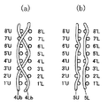
- FIG. 2A is a longitudinal sectional view cut along warp binding yarns 4Ub and 4Lb in FIG. 1
- FIG. 2B is an upper surface side warp 5U and lower surface side warp 5L in FIG.
- FIG. 2A shows typically the longitudinal cross-sectional view cut
- FIG. 2B is an upper surface side warp 5U and lower surface side warp 5L in FIG.
- FIG. 2A is a longitudinal sectional view cut along warp binding yarns 4Ub and 4Lb in FIG. 1
- FIG. 2B is an upper surface side warp 5U and lower surface side warp 5L in FIG.
- FIG. 2A shows typically the longitudinal cross-sectional view cut
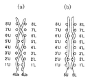
- FIG. 4A is a longitudinal sectional view cut along warp binding yarns 4Ub and 4Lb in FIG. 3, and FIG. 4B is an upper surface side warp 5U and lower surface side warp 5L in FIG. It is the longitudinal cross-sectional view cut
- FIG. 6 (a) is a longitudinal sectional view cut along warp binding yarns 4Ub and 4Lb in FIG. 5, and
- FIG. 6 (b) is an upper surface side warp 5U and lower surface side warp 5L in FIG. It is the longitudinal cross-sectional view cut
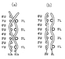
- FIG. 8A is a longitudinal sectional view cut along warp binding yarns 1Ub and 1Lb in FIG. 7, and FIG. 8B is an upper surface side warp 2U and lower surface side warp 2L in FIG. It is the longitudinal cross-sectional view cut
- FIG. 7 is a longitudinal cross-sectional view cut along the warp binding yarn 1Ub in FIG. 7, a longitudinal cross-sectional view cut along the upper surface side warps 2U and 2L, and is cut along the warp binding yarn 3Ub. It is the longitudinal cross-sectional view cut
- FIG. 13A is a longitudinal sectional view cut along warp binding yarns 3Ub and 3Lb in FIG. 12, and FIG. 13B is an upper surface side warp 4U and lower surface side warp 4L in FIG. It is the longitudinal cross-sectional view cut
- FIG. 15A is a longitudinal sectional view cut along warp binding yarns 1Ub and 1Lb in FIG. 14, and FIG. 15B is an upper surface side warp 2U and lower surface side warp 2L in FIG. It is the longitudinal cross-sectional view cut
- the industrial two-layer fabric according to the present invention functions as an upper surface side fabric composed of an upper surface side warp and an upper surface side weft, a lower surface side fabric composed of a lower surface side warp and a lower surface side weft, and a warp binding yarn.
- the upper surface side warp and the lower surface side warp function as a warp binding yarn.
- the warp binding yarn in the present invention is not simply a yarn having a function of binding the upper surface side fabric and the lower surface side fabric, but forms a surface texture in the upper surface side fabric together with the upper surface side warp.
- the industrial two-layer woven fabric according to the present invention has the upper surface side wefts functioning as warp binding yarns woven with the upper surface side wefts at the site where the upper surface side wefts are woven into the fabric structure at one or more positions of the complete structure.
- the lower surface side warp functions as the warp binding yarn while the lower surface side warp functions as the warp binding yarn.
- the lower surface side weft is not woven from the lower surface side weft from the lower surface side, and the upper surface side weft is not woven from the upper surface side toward the upper surface side. It has a feature in that it is an organization that weaves.
- the upper layer side structure and the lower layer side structure are not collapsed, and the wire mark characteristics are also good.
- the yarn that functions as the binding yarn is a ground yarn that constitutes the woven fabric structure, and is a warp yarn that is always tensioned during use, it is higher than using a weft binding yarn.
- the bonding force for bonding the layer surface side fabric and the lower layer surface side fabric is very strong, and since the force for always bringing the upper layer surface fabric and the lower layer side fabric into close contact works, the adhesion is good. Accordingly, there is no problem that the binding yarn is squeezed between the two fabrics to cause internal wear and the binding force is weakened, and a gap is generated between the two fabrics or separated.
- the industrial two-layer woven fabric according to the present invention has a joining loop formed by folding back part or all of the warp yarns at both ends that are the longitudinal direction and the end of the woven fabric that is the traveling direction of the belt.
- the warp yarns in the complete structure have a pair of warps facing the folded warp yarns to form the joining loop, and the warp yarns in the pair have the same number of knuckles in the warp structure And the knuckles have substantially the same shape, and the intervals between the knuckles are substantially equal.
- the knuckle has substantially the same shape as that having the meaning of excluding that it is physically completely the same.
- the other warp pair also has three warp yarns
- the knuckle has the same shape because it has a structure that passes above and then passes under one lower surface side weft.
- the expression “the interval between knuckles is substantially equal” has the same meaning.
- the density of the number of yarns with respect to the upper surface side fabric is not particularly limited, and the lower surface side wefts can have the same density as the upper surface side, or a density such as 1/2 or 2/3.
- the yarn used in the present invention can be freely selected depending on the properties desired for the papermaking fabric and is not particularly limited. For example, in addition to monofilament, multifilament, spun yarn, crimped or bulky processed textured yarn, bulky yarn, processed yarn called stretch yarn, mould yarn, or these are combined. Can be used.
- the cross-sectional shape of the yarn is not limited to a circle, and a rectangular yarn such as a square shape or a star shape, an elliptical shape, a hollow yarn, or the like can be used.
- the material of the yarn can also be freely selected, and polyester, nylon, polyphenylene sulfide, polyvinylidene fluoride, tetrafluoroethylene, polypro, aramid, polyetheretherketone, polyethylene naphthalate, cotton, wool, metal, etc. can be used. .
- polyester nylon, polyphenylene sulfide, polyvinylidene fluoride, tetrafluoroethylene, polypro, aramid, polyetheretherketone, polyethylene naphthalate, cotton, wool, metal, etc.
- the lower surface side wefts that require wear resistance can be improved in wear resistance while ensuring rigidity by interweaving polyester monofilaments and nylon monofilaments.
- a plurality of yarns can be arranged in the same structure where a single thread is originally arranged. By arranging a plurality of thin wire diameter yarns, the surface property can be improved and the thickness of the fabric can be reduced.
- FIG. 1 is a design diagram showing a complete structure of an embodiment according to the present invention.
- the complete structure is a minimum repeating unit of the woven structure, and this complete structure is connected vertically and horizontally to form the entire structure of the woven fabric.
- the warp is indicated by Arabic numerals, for example 1, 2, 3, and the weft is indicated by Arabic numerals with dashes, for example, 1 ', 2', 3 ', and U is the yarn of the upper side fabric.
- L indicates that it is a thread of the lower surface side fabric.
- the warp functioning as a binding yarn is indicated by 1 Ub and 2 Lb, for example, by adding b.
- X indicates that the upper surface side warp is located above the upper surface side weft
- ⁇ indicates that the lower surface side warp is located below the lower surface side weft
- ⁇ indicates warp
- the ⁇ mark indicates that the upper side warp that functions as the warp binding yarn is located below the lower side weft.
- ⁇ indicates the lower side that functions as the warp binding yarn It shows that the warp is located below the lower side weft.
- the upper side and lower side warps and wefts are arranged one above the other. In the design drawing, the upper and lower warps are arranged with the yarns accurately overlapped vertically, and the lower warp and weft are arranged just below the weft. In the woven fabric, they may be displaced.
- Embodiment 1 1 and 2 are a design diagram and a partial longitudinal sectional view for explaining an industrial two-layer fabric according to Embodiment 1 of the present invention.
- the industrial two-layer fabric according to the first embodiment includes an upper surface side warp (1U, 2U, 3U, 5U, 6U, 7U) and a lower surface side warp (1L, 2L, 3L, 5L, 6L). 7L), an upper shaft side warp (4 Ub, 8 Ub) that functions as a warp binding yarn, and a lower surface side warp (4 Lb, 8 Lb) that functions as a warp binding yarn.
- the arrangement ratio of the upper surface side wefts (1′U, 2′U%) And the lower surface side wefts (1′L, 2′L%) Is 1: 1.
- the upper surface side warp functioning as the warp binding yarn is the upper surface side warp (4Ub) at one place (4′U, 5′U, 6 ′) in the complete structure.
- the upper surface side wefts are not woven at the part where the upper surface side wefts are woven in the fabric structure, but the lower surface side wefts (5'L) are woven from the lower surface side toward the lower surface side, and the other upper surface side wefts are moved toward the upper surface side. It is a weaving organization.
- the lower surface side warp (4Lb) is a portion where the upper surface side warp (4Ub) functioning as the warp binding yarn is woven from the lower surface side weft (5'L) from the lower surface side. ), Weaving the upper surface side wefts (4'U, 5'U, 6'U) from the upper surface side and weaving the other lower surface side wefts toward the lower surface side. It is an organization. Further, as shown in FIG. 2B, the upper surface side warp (5U) includes upper surface side wefts (1'U, 3'U, 4'U, 5'U, 7'U, 8'U) at two locations.
- the lower surface side warp (5L) is woven from the lower surface side at two locations on the lower surface side wefts (4'L, 8'L).
- a joining loop is formed by folding back part or all of the warp at both ends that are longitudinal and end-like.
- a pair of warp yarns is composed of an upper surface side warp, a lower surface side warp, and warp binding yarns.
- the warp yarns in the complete structure have the same number of knuckles in the warp structure as the pair of warp yarns opposed to the folded warp yarns to form the joining loop, and the intervals between the knuckles are substantially equal. ing.
- Embodiment 2 3 and 4 are a design diagram and a partial longitudinal sectional view for explaining an industrial two-layer fabric according to Embodiment 2 of the present invention.
- the industrial two-layer fabric according to the second embodiment includes an upper surface side warp (1U, 2U, 3U, 5U, 6U, 7U) and a lower surface side warp (1L, 2L, 3L, 5L, 6L). 7L), an upper shaft side warp (4 Ub, 8 Ub) that functions as a warp binding yarn, and a lower surface side warp (4 Lb, 8 Lb) that functions as a warp binding yarn.
- the arrangement ratio of the upper surface side wefts (1′U, 2′U%) And the lower surface side wefts (1′L, 2′L%) Is 1: 1.
- the upper surface side warp functioning as the warp binding yarn is the upper surface on the woven fabric structure with the upper surface side warp (4Ub) in one place (5'U) of the complete structure.
- the upper weft is not woven at the site where the side weft is woven, but the lower surface weft (5′L) is woven from the lower surface side toward the lower surface side, and the other upper surface weft is woven toward the upper surface side.
- the lower surface side warp (4Lb) is a portion where the upper surface side warp (4Ub) functioning as the warp binding yarn is woven from the lower surface side weft (5'L) from the lower surface side. ) And weaving the upper surface side weft (5′U) from which the upper surface side warp is not woven toward the upper surface side, and weaving the other lower surface weft toward the lower surface side. 4B, the upper surface side warp (5U) weaves the upper surface side wefts (2′U, 6′U) from the upper surface side at two locations, and the lower surface side warp (5L) 2'L, 6'L) are woven from the lower surface side at two locations.
- a joining loop is formed by folding back part or all of the warp at both ends that are longitudinal and end-like.
- a pair of warp yarns is composed of an upper surface side warp, a lower surface side warp, and warp binding yarns.
- the warp yarns in the complete structure have the same number of knuckles in the warp structure as the pair of warp yarns opposed to the folded warp yarns to form the joining loop, and the intervals between the knuckles are substantially equal. ing. Even by adopting such a structure, a loop structure for binding using warps is formed at both ends of an industrial two-layer fabric of a ground yarn binding type, which was difficult with the conventional loop structure for binding. be able to.
- Embodiment 3 5 and 6 are a design diagram and a partial longitudinal sectional view for explaining an industrial two-layer fabric according to Embodiment 3 of the present invention.
- the industrial two-layer fabric according to the third embodiment includes an upper surface side warp (1U, 2U, 3U, 5U, 6U, 7U) and a lower surface side warp (1L, 2L, 3L, 5L, 6L). 7L), an upper shaft side warp (4 Ub, 8 Ub) that functions as a warp binding yarn, and a lower surface side warp (4 Lb, 8 Lb) that functions as a warp binding yarn.
- the arrangement ratio of the upper surface side wefts (1′U, 2′U%) And the lower surface side wefts (1′L, 3′L%) Is 2: 1.
- the upper surface side warp functioning as the warp binding yarn is the upper surface on the fabric structure with the upper surface side warp (4Ub) at one place (5'U) in the complete structure.
- the upper weft is not woven at the site where the side weft is woven, but the lower surface weft (5′L) is woven from the lower surface side toward the lower surface side, and the other upper surface weft is woven toward the upper surface side.
- the lower surface side warp (4Lb) is a portion where the upper surface side warp (4Ub) functioning as the warp binding yarn is woven from the lower surface side weft (5'L) from the lower surface side. ) And weaving the upper surface side weft (5′U) from which the upper surface side warp is not woven toward the upper surface side, and weaving the other lower surface weft toward the lower surface side.
- the upper surface side warp (5U) weaves the upper surface side wefts (2'U, 6'U) from the upper surface side at two locations, and the lower surface side warp (5L) 1′L, 5′L) are woven in two places from the lower surface side.
- a joining loop is formed by folding back part or all of the warp at both ends that are longitudinal and end-like.
- a pair of warp yarns is composed of an upper surface side warp, a lower surface side warp, and warp binding yarns.
- the warp yarns in the complete structure have the same number of knuckles in the warp structure as the pair of warp yarns opposed to the folded warp yarns to form the joining loop, and the intervals between the knuckles are substantially equal. ing. Even by adopting such a structure, a loop structure for binding using warps is formed at both ends of an industrial two-layer fabric of a ground yarn binding type, which was difficult with the conventional loop structure for binding. be able to.
- Embodiment 4 7 to 11 are a design diagram, a longitudinal sectional view, and a sectional partial photograph for explaining an industrial two-layer fabric according to Embodiment 4 of the present invention.
- the industrial two-layer fabric according to the fourth embodiment includes an upper surface side warp (2U, 4U, 6U, 8U), a lower surface side warp (2L, 4L, 6L, 8L), and a warp yarn.
- This is an 8-shaft woven fabric composed of upper surface side warps (1 Ub, 3 Ub, 5 Ub, 7 Ub) that function as binding yarns and lower surface side warps (1 Lb, 3 Lb, 5 Lb, 7 Lb) that function as warp binding yarns.
- the arrangement ratio of the upper surface side wefts (1′U, 2′U%) And the lower surface side wefts (1′L, 3′L%) Is 2: 1.
- the upper surface side warp functioning as the warp binding yarn is the upper surface side warp (1 Ub) at one place (5′U, 6′U) in the complete structure.
- the upper weft yarn is not woven at the site where the upper surface side weft is woven, and the lower surface side weft yarn (5'L) is woven from the lower surface side toward the lower surface side, and the other upper surface weft yarn is woven toward the upper surface side. .
- the lower surface side weft (1'Lb) is a portion where the upper surface side warp (1Ub) functioning as the warp binding yarn is woven from the lower surface side weft (5'L) from the lower surface side. ), And weaving the upper surface side wefts (5′U, 6′U) from which the upper surface side warps are not woven toward the upper surface side, and weaving other lower surface side wefts toward the lower surface side. Further, as shown in FIG.
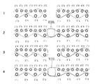
- FIG. 9 is a conceptual longitudinal sectional view showing both end portions of the industrial two-layer fabric according to the fourth embodiment. As shown in FIG. 9, along the warp yarns at the 1Ub and 1Lb warp binding locations, 2U and 2L warp locations, 3Ub and 3Lb warp binding locations, and 4U and 4L locations from the top FIG.
- the upper surface side warp 1Ub that functions as a warp binding yarn is folded back on the upper surface side weft 6'U, and the lower surface side warp 1Lb that functions as a warp binding yarn originally is
- the lower surface side weft 5'L to be woven is woven from the lower surface side, and then the upper surface side wefts 2'U and 1'U are woven from the upper surface side.
- the upper surface side warp 2U is folded back to form the joining loop WSBL, and the lower surface side weft 7'L which the lower surface side warp 2L is originally woven is formed from the lower surface side. Weaving, then 3'L is woven from the lower surface side.
- the upper surface side warp 2U is folded back to form a joining loop WSBL, and the lower surface side wefts 3'L, 7 which the lower surface side warp 2L is originally woven into. 'L is woven from the bottom side.
- the upper surface side warp 3Ub that functions as a warp binding yarn forms a stop by weaving the upper surface side wefts 6'U and 7'U from the upper surface side, Side wefts 3'U and 2'U are woven from the upper surface side.
- the upper surface side warps 4U are folded back by forming a joining loop WSBL, and the lower surface side wefts 5'U, 1'U that the lower surface side warps 4L are woven are originally. Weaving from the bottom side.
- the warp yarns in the complete structure have a pair of warp yarns opposed to the folded warp yarns to form the joining loop WSBL, and the warp yarns in the pair have a number of knuckles in the warp structure. It can be seen that the distances between the knuckles are substantially the same. Even by adopting such a structure, a loop structure for binding using warps is formed at both ends of an industrial two-layer fabric of a ground yarn binding type, which was difficult with the conventional loop structure for binding. be able to.
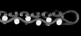
- FIG. 10 is a vertical cross-sectional photograph at the third position in the third row from the top in FIG.
- FIG. 11 is a photograph of a longitudinal section at four points of four sections from the top in FIG. It can be seen that the upper surface side warp 4U is folded back to form a joining loop WSBL, and the lower surface side wefts 5'U and 1'U are woven from the lower surface side.
- Embodiment 5 12 and 13 are a design diagram and a partial longitudinal sectional view for explaining an industrial two-layer fabric according to Embodiment 5 of the present invention.
- the industrial two-layer fabric according to the fifth embodiment includes an upper surface side warp (1U, 2U, 4U, 5U), a lower surface side warp (1L, 2L, 4L, 5L), and a warp yarn.
- This is a 12-shaft fabric composed of upper surface side warps (3 Ub, 6 Ub) that function as binding yarns and lower surface side warps (3 Lb, 6 Lb) that function as warp binding yarns.
- the arrangement ratio of the upper surface side wefts (1′U, 2′U%) And the lower surface side wefts (1′L, 2′L%) Is 1: 1.
- the upper surface side warp functioning as a warp binding yarn has three upper surface side warps (3Ub) (7′U, 9′U, 11 ′).
- the upper surface side wefts are not woven at the part where the upper surface side wefts are woven in the fabric structure, but the lower surface side wefts (9'L) are woven from the lower surface side toward the lower surface side and the other upper surface side wefts are moved toward the upper surface side. It is a weaving organization.
- the lower surface side warp (3Lb) is a portion where the upper surface side warp (3Ub) functioning as the warp binding yarn is woven from the lower surface side weft (9'L) from the lower surface side. ), Weaving the upper surface side wefts (7'U, 9'U, 11'U) from which the upper surface side warp was not woven toward the upper surface side, and weaving the other lower surface side wefts toward the lower surface side. It is an organization. Further, as shown in FIG. 13B, the upper surface side warp (4U) is a plain weave, and the lower surface side warp (4L) is woven from the lower surface side wefts (6′L, 12′L) from the lower surface side.
- a joining loop is formed by folding back part or all of the warp at both ends that are longitudinal and end-like.
- the pair of warp yarns is composed of upper surface side warps, lower surface side warps, and warp binding yarns.
- the warp yarns in the complete structure have the same number of knuckles in the warp structure as the pair of warp yarns opposed to the folded warp yarns to form the joining loop, and the intervals between the knuckles are substantially equal. ing. Even by adopting such a structure, a loop structure for binding using warp yarns is formed at both ends of an industrial two-layer fabric for binding yarn, which was difficult with the conventional loop structure for binding.
- Embodiment 6 14 and 15 are a design diagram and a partial longitudinal sectional view for explaining an industrial two-layer fabric according to Embodiment 6 of the present invention.
- the industrial two-layer fabric according to the sixth embodiment includes an upper surface side warp (2U, 3U, 4U, 5U, 7U, 8U, 9U, 10U) and a lower surface side warp (2L, 3L, 4L). 5L, 7L, 8L, 9L, 10L), an upper surface side warp (1Ub, 6Ub) that functions as a warp binding yarn, and a lower surface side warp (1Lb, 6Lb) that functions as a warp binding yarn
- This is a 20 shaft fabric.
- the arrangement ratio of the upper surface side wefts (1′U, 2′U%) And the lower surface side wefts (1′L, 2′L%) Is 1: 1.
- the upper surface side warp functioning as a warp binding yarn has two upper surface side warp yarns (1Ub) (11′U, 12′U, 13 ′).
- the upper surface side weft is not woven at the portion where the upper surface side weft is woven on the fabric structure, and the lower surface side weft (12′L) from the lower surface side toward the lower surface side.
- the lower surface side warp (1Lb) is a portion where the upper surface side warp (1Ub) functioning as the warp binding yarn weaves the lower surface side wefts (12'L) and (17'L) from the lower surface side.
- 17′U, 18′U) from the upper surface side and weaving the other lower surface side wefts toward the lower surface side.
- the upper surface side warp (2U) is woven by 3/2
- the lower surface side warp (2L) is woven by 4/1.
- a joining loop is formed by folding back part or all of the warp at both ends that are longitudinal and end-like.
- the pair of warps are composed of warp binding yarns, adjacent upper surface side warps and upper surface side warps, and adjacent lower surface side warps and lower surface side warps.
- the warp yarn in the complete structure has a pair of warps facing the folded warp to form the joining loop, and the warp yarns in the pair have the same number of knuckles in the warp structure. The intervals between the knuckles are substantially equal. Even by adopting such a structure, a loop structure for binding using warps is formed at both ends of an industrial two-layer fabric of a ground yarn binding type, which was difficult with the conventional loop structure for binding. be able to.
Landscapes
- Engineering & Computer Science (AREA)
- Textile Engineering (AREA)
- Woven Fabrics (AREA)
- Paper (AREA)
Abstract
Description
上記のような工業用織物は、無端状に加工され、抄紙機や脱水機等のそれぞれの機械に取り付けられて使用する必要がある。
例えば、古い使用済みの工業用織物を装置に取り付けられている状態で有端状にした後、その一端にこれから取り付ける新しい工業用織物の一端を接合し、装置を作動することができる。これにより工業用織物を装置のロール間を移動させて掛け渡し、織物が1周して全体に掛け渡った後を確認した後に、古い工業用織物を取り外して、新しい工業用織物を無端状に形成して取り付けることができる。
そのため新規な経地糸接結糸を使用した工業用二層織物等の自由に無端状や有端状に形成することが不可能な織継方法の場合は、装置におけるロールを片側で支え、反対側の邪魔になる支柱等を取り外して工業用織物を装置の片側から巾方向に向かって挿入して掛け入れる、いわゆるカンチレバー方式によって行なう必要が生じる。しかしながら、カンチレバー方式で織継方法を行うには、機械自体に織物を脱着するための特殊な構造が必要となり、機械の製造コストが高くなる欠点があった。又、装置が大型になる欠点や、広い設置スペースが必要となる等の欠点も指摘されていた。更に、重量が大きかったり非常に長い工業用織物を使用する場合には、織物を挿入するのが困難であるという問題点がある。
(1)上面側経糸と上面側緯糸とからなる上面側織物と、下面側経糸と下面側緯糸とからなる下面側織物と、経地糸接結糸として機能する上面側経糸と経地糸接結糸として機能する下面側経糸との組からなる工業用二層織物において、経地糸接結糸として機能する上面側経糸は上面側経糸が完全組織の1箇所または複数箇所にて織物組織上上面側緯糸を織り込む部位で上面側緯糸を織り込まず、下面側に向かって下面側から下面側緯糸を織り込んで上面側に向かい他の上面側緯糸を織り込む組織であり、一方下面側経糸は該経地糸接結糸として機能する上面側経糸が下面側緯糸を下面側から織り込んだ部位で該下面側緯糸を織り込まず、上面側に向かって上面側経糸を織り込まなかった上面側緯糸を上面側から織り込んで下面側に向かい他の下面側緯糸を織り込む組織であり、当該工業用二層織物は縦方向であって有端状である両端部において経糸の一部又は全端部を折り返すことにより接合用ループを形成し、完全組織内の縦糸は前記接合用ループを形成するため折り返された経糸と対向するペアとなる経糸を有しており、当該ペアとなる経糸同士は縦組織においてナックルの数が同じであり、かつナックル間の間隔が略等しいことを特徴とする工業用二層織物である。
(3)対向するペアとなる経糸が、経地糸接結糸同士、隣接する上面側経糸と上面側経糸、及び隣接する下面側経糸と下面側経糸とから構成されていることを特徴とする上記(1)に記載された工業用二層織物である。
本発明に係る工業用二層織物は、上面側経糸と上面側緯糸とからなる上面側織物と、下面側経糸と下面側緯糸とからなる下面側織物と、経地糸接結糸として機能する上面側経糸と経地糸接結糸として機能する下面側経糸との組からなる構成されている。
ここで、本発明において経地糸接結糸とは、単に上面側織物と下面側織物とを接結する機能を有するだけの糸ではなく、上面側経糸とともに上面側織物における表面組織を形成する機能と上面側織物と下面側織物とを接結する機能とを有する糸のことである。
また本発明に係る工業用二層織物は、経地糸接結糸として機能する上面側経糸が完全組織の1箇所または複数箇所にて織物組織上上面側緯糸を織り込む部位で上面側緯糸を織り込まず、下面側に向かって下面側から下面側緯糸を織り込んで上面側に向かい他の上面側緯糸を織り込む組織であり、一方、下面側経糸は該経地糸接結糸として機能する上面側経糸が下面側緯糸を下面側から織り込んだ部位で該下面側緯糸を織り込まず、上面側に向かって上面側経糸を織り込まなかった上面側緯糸を上面側から織り込んで下面側に向かい他の下面側緯糸を織り込む組織である点に特徴を有する。
さらに本発明に係る工業用二層織物は、ベルトの進行方向となる織物の縦方向であって有端状である両端部において、経糸の一部又は全端部を折り返すことにより接合用ループを形成し、完全組織内の縦糸は前記接合用ループを形成するため折り返された経糸と対向するペアとなる経糸を有しており、前記ペアとなる経糸同士は縦組織においてナックルの数が同じであり、ナックルが略同形状であり、かつナックル間の間隔が略等しいことを特徴とする。
ここでナックルの形状が略同形状とは物理的に完全同一であることを排除する意義を有している。例えば、経糸が3本の上面側緯糸の上を通り、次いで1本の下面側緯糸の下を通る接続糸の場合、ペアとなる他の経糸も同じように経糸が3本の上面側緯糸の上を通り、次いで1本の下面側緯糸の下を通る構造を有しているため、ナックルの形状が同一となることを示している。また、「ナックル間の間隔が略等しい」という表現も同様の趣旨である。このようにペアとなる経糸同士のナックルを等しくしたことにより、経糸と緯糸のかみ合わせが収まり、ループ際部の網面が綺麗になる。
本発明に使用される糸としては、製紙用織物に望まれる特性によって自由に選択でき特に限定されない。例えばモノフイラメントの他、マルチフイラメント、スパンヤーン、捲縮加工や嵩高加工等を施した一般的にテクスチャードヤーン、バルキーヤーン、ストレッチヤーンと称される加工糸、モール糸、あるいはこれらをより合わせる等して組み合わせた糸等が使用できる。また、糸の断面形状も円形だけでなく四角形状や星型等の矩形状の糸や楕円形状、中空等の糸が使用できる。また、糸の材質としても自由に選択でき、ポリエステル、ナイロン、ポリフェニレンサルファイド、ポリフッ化ビニリデン、4フッ化エチレン、ポリプロ、アラミド、ポリエーテルエーテルケトン、ポリエチレンナフタレート、綿、ウール、金属等が使用できる。勿論、共重合体やこれらの材質に目的に応じて色々な物質をブレンドしたり含有させた糸を使用しても良い。
一般的には、上層面側経糸、下層面側経糸、上層面側緯糸には剛性があり、寸法安定性が優れているポリエステルモノフイラメントを用いるのが好ましい。また、耐摩耗性が要求される下層面側緯糸は、ポリエステルモノフイラメントとナイロンモノフイラメントを交互に配置する等、交織して剛性を確保しつつ耐摩耗性を向上させることもできる。
また、組織上は本来1本の糸が配置される部分に、同組織で糸を複数本引き揃えて配置することもできる。細い線径の糸を複数本引き揃えて配置することによって、表面性の向上と織物の厚みを薄くすることができる。
図1は、本発明に係る実施形態の完全組織を示す意匠図である。完全組織とは、織物組織の最小の繰り返し単位であって、この完全組織が上下左右につながって織物全体の組織が形成される。意匠図において、経糸はアラビア数字、例えば1、2、3、で示し、緯糸はダッシュを付したアラビア数字、例えば1´、2´、3´、で示し、Uは上面側織物の糸であることを示し、Lは下面側織物の糸であることを示す。また、接結糸として機能する経糸はbを加えることで、例えば1Ub、2Lbで示す。
また、×印は上面側経糸が上面側緯糸の上側に位置していることを示し、○印は下面側経糸が下面側緯糸の下側に位置していることを示し、▲印は経地糸接結糸として機能する上面側経糸が上面側緯糸の上側に位置していることを示し、△印は経地糸接結糸として機能する上面側経糸が下面側緯糸の下側に位置していることを示し、■印は経地糸接結糸として機能する下面側経糸が上面側緯糸の上側に位置していることを示し、□印は経地糸接結糸として機能する下面側経糸が下面側緯糸の下側に位置していることを示す。
上面側と下面側の経糸、緯糸は上下に重なって配置されている。尚、意匠図では糸が上下に正確に重なって上面側の経糸、緯糸の真下に下面側の経糸、緯糸が配置されることになっているが、これは図面の都合上であって実際の織物ではずれて配置されても構わないものである。
図1及び図2は、本発明の実施形態1に係る工業用二層織物を説明するための意匠図及び部分的な縦断面図である。
図1に示す如く、本実施形態1に係る工業用二層織物は、上面側経糸(1U、2U、3U、5U、6U、7U)と、下面側経糸(1L、2L、3L、5L、6L、7L)と、経地糸接結糸として機能する上面側経糸(4Ub、8Ub)と、経地糸接結糸として機能する下面側経糸(4Lb、8Lb)からなる8シャフトの織物である。上面側緯糸(1’U、2’U・・・)と下面側緯糸(1’L、2’L・・・)の配置比率は1:1である。
本実施形態において、図2(a)に示す如く、経地糸接結糸として機能する上面側経糸は上面側経糸(4Ub)が完全組織の1箇所(4’U、5’U、6’U)にて織物組織上上面側緯糸を織り込む部位で上面側緯糸を織り込まず、下面側に向かって下面側から下面側緯糸(5’L)を織り込んで上面側に向かい他の上面側緯糸を織り込む組織である。一方、下面側経糸(4Lb)は前記経地糸接結糸として機能する上面側経糸(4Ub)が下面側緯糸(5’L)を下面側から織り込んだ部位で前記下面側緯糸(5’L)を織り込まず、上面側に向かって上面側経糸が織り込まなかった上面側緯糸(4’U、5’U、6’U)を上面側から織り込んで下面側に向かい他の下面側緯糸を織り込む組織である。
また、図2(b)に示す如く、上面側経糸(5U)は上面側緯糸(1’U、3’U、4’U、5’U、7’U、8’U)を2箇所で上面側から織り込み、下面側経糸(5L)は下面側緯糸(4’L、8’L)を2箇所で下面側から織り込んでいる。
本実施形態において、図示しないが、縦方向であって有端状である両端部において経糸の一部又は全端部を折り返すことにより接合用ループを形成している。本実施形態1に係る工業用二層織物において、ペアとなる経糸は、上面側経糸と下面側経糸、経地糸接結糸同士で構成されている。
また、完全組織内の縦糸は前記接合用ループを形成するため折り返された経糸と対向するペアとなる経糸とは、縦組織においてナックルの数が同じであり、かつナックル間の間隔が略等しくなっている。
このような組織を採用することにより、従来の接結用ループ構造では困難であった地糸接結タイプの工業用二層織物の両端部に経糸を使用した接結用ループ構造を形成することができる。
図3及び図4は、本発明の実施形態2に係る工業用二層織物を説明するための意匠図及び部分的な縦断面図である。
図3に示す如く、本実施形態2に係る工業用二層織物は、上面側経糸(1U、2U、3U、5U、6U、7U)と、下面側経糸(1L、2L、3L、5L、6L、7L)と、経地糸接結糸として機能する上面側経糸(4Ub、8Ub)と、経地糸接結糸として機能する下面側経糸(4Lb、8Lb)からなる8シャフトの織物である。上面側緯糸(1’U、2’U・・・)と下面側緯糸(1’L、2’L・・・)の配置比率は1:1である。
本実施形態において、図4(a)に示す如く、経地糸接結糸として機能する上面側経糸は上面側経糸(4Ub)が完全組織の1箇所(5’U)にて織物組織上上面側緯糸を織り込む部位で上面側緯糸を織り込まず、下面側に向かって下面側から下面側緯糸(5’L)を織り込んで上面側に向かい他の上面側緯糸を織り込む組織である。一方、下面側経糸(4Lb)は前記経地糸接結糸として機能する上面側経糸(4Ub)が下面側緯糸(5’L)を下面側から織り込んだ部位で前記下面側緯糸(5’L)を織り込まず、上面側に向かって上面側経糸が織り込まなかった上面側緯糸(5’U)を上面側から織り込んで下面側に向かい他の下面側緯糸を織り込む組織である。
また、図4(b)に示す如く、上面側経糸(5U)は上面側緯糸(2’U、6’U)を2箇所で上面側から織り込み、下面側経糸(5L)は下面側緯糸(2’L、6’L)を2箇所で下面側から織り込んでいる。
本実施形態において、図示しないが、縦方向であって有端状である両端部において経糸の一部又は全端部を折り返すことにより接合用ループを形成している。本実施形態2に係る工業用二層織物において、ペアとなる経糸は、上面側経糸と下面側経糸、経地糸接結糸同士で構成されている。
また、完全組織内の縦糸は前記接合用ループを形成するため折り返された経糸と対向するペアとなる経糸とは、縦組織においてナックルの数が同じであり、かつナックル間の間隔が略等しくなっている。
このような組織を採用することによっても、従来の接結用ループ構造では困難であった地糸接結タイプの工業用二層織物の両端部に経糸を使用した接結用ループ構造を形成することができる。
図5及び図6は、本発明の実施形態3に係る工業用二層織物を説明するための意匠図及び部分的な縦断面図である。
図5に示す如く、本実施形態3に係る工業用二層織物は、上面側経糸(1U、2U、3U、5U、6U、7U)と、下面側経糸(1L、2L、3L、5L、6L、7L)と、経地糸接結糸として機能する上面側経糸(4Ub、8Ub)と、経地糸接結糸として機能する下面側経糸(4Lb、8Lb)からなる8シャフトの織物である。上面側緯糸(1’U、2’U・・・)と下面側緯糸(1’L、3’L・・・)の配置比率は2:1である。
本実施形態において、図6(a)に示す如く、経地糸接結糸として機能する上面側経糸は上面側経糸(4Ub)が完全組織の1箇所(5’U)にて織物組織上上面側緯糸を織り込む部位で上面側緯糸を織り込まず、下面側に向かって下面側から下面側緯糸(5’L)を織り込んで上面側に向かい他の上面側緯糸を織り込む組織である。一方、下面側経糸(4Lb)は前記経地糸接結糸として機能する上面側経糸(4Ub)が下面側緯糸(5’L)を下面側から織り込んだ部位で前記下面側緯糸(5’L)を織り込まず、上面側に向かって上面側経糸が織り込まなかった上面側緯糸(5’U)を上面側から織り込んで下面側に向かい他の下面側緯糸を織り込む組織である。
また、図6(b)に示す如く、上面側経糸(5U)は上面側緯糸(2’U、6’U)を2箇所で上面側から織り込み、下面側経糸(5L)は下面側緯糸(1’L、5’L)を2箇所で下面側から織り込んでいる。
本実施形態において、図示しないが、縦方向であって有端状である両端部において経糸の一部又は全端部を折り返すことにより接合用ループを形成している。本実施形態3に係る工業用二層織物において、ペアとなる経糸は、上面側経糸と下面側経糸、経地糸接結糸同士で構成されている。
また、完全組織内の縦糸は前記接合用ループを形成するため折り返された経糸と対向するペアとなる経糸とは、縦組織においてナックルの数が同じであり、かつナックル間の間隔が略等しくなっている。
このような組織を採用することによっても、従来の接結用ループ構造では困難であった地糸接結タイプの工業用二層織物の両端部に経糸を使用した接結用ループ構造を形成することができる。
図7乃至図11は、本発明の実施形態4に係る工業用二層織物を説明するための意匠図、縦断面図及び断面部分写真である。
図7に示す如く、本実施形態4に係る工業用二層織物は、上面側経糸(2U、4U、6U、8U)と、下面側経糸(2L、4L、6L、8L)と、経地糸接結糸として機能する上面側経糸(1Ub、3Ub、5Ub、7Ub)と、経地糸接結糸として機能する下面側経糸(1Lb、3Lb、5Lb、7Lb)からなる8シャフトの織物である。上面側緯糸(1’U、2’U・・・)と下面側緯糸(1’L、3’L・・・)の配置比率は2:1である。
本実施形態において、図8(a)に示す如く、経地糸接結糸として機能する上面側経糸は上面側経糸(1Ub)が完全組織の1箇所(5’U、6’U)にて織物組織上上面側緯糸を織り込む部位で上面側緯糸を織り込まず、下面側に向かって下面側から下面側緯糸(5’L)を織り込んで上面側に向かい他の上面側緯糸を織り込む組織である。一方、下面側経糸(1Lb)は前記経地糸接結糸として機能する上面側経糸(1Ub)が下面側緯糸(5’L)を下面側から織り込んだ部位で前記下面側緯糸(5’L)を織り込まず、上面側に向かって上面側経糸が織り込まなかった上面側緯糸(5’U、6’U)を上面側から織り込んで下面側に向かい他の下面側緯糸を織り込む組織である。
また、図8(b)に示す如く、上面側経糸(2U)は上面側緯糸(3’U、4’U)及び(7’U、8’U)を2箇所で上面側から織り込み、下面側経糸(2L)は下面側緯糸(3’U、7’u)を2箇所で下面側から織り込んでいる。
図9は、実施形態4に係る工業用二層織物の両端部を示す概念縦断面図である。図9に示す如く、上から1Ubと1Lbの経地糸接結糸の箇所、2Uと2Lの経糸の箇所、3Ubと3Lb経地糸接結糸の箇所、4Uと4Lの箇所における経糸に沿って切断した縦断面図を示している。
また、上から2段面の2の箇所においては、上面側経糸2Uが接合用ループWSBLを形成して折り返され、本来であれば下面側経糸2Lが織り込む下面側緯糸7’Lを下面側から織り込み、次いで3’Lを下面側から織り込む。工業用二層織物の対面する反対側の端部においても、上面側経糸2Uが接合用ループWSBLを形成して折り返され、本来であれば下面側経糸2Lが織り込む下面側緯糸3’L、7’Lを下面側から織り込む。
また、上から3段目の3の箇所においては、経地糸接結糸として機能する上面側経糸3Ubが上面側緯糸6’U、7’Uを上面側から織り込んで止めを形成し、上面側緯糸3’U、2’Uを上面側から織り込んでいる。
さらに、上から4段面の4の箇所においては、上面側経糸4Uが接合用ループWSBLを形成して折り返され、本来であれば下面側経糸4Lが織り込む下面側緯糸5’U、1’Uを下面側から織り込む。
上記のように完全組織内の縦糸は前記接合用ループWSBLを形成するため折り返された経糸と対向するペアとなる経糸を有しており、当該ペアとなる経糸同士は縦組織においてナックルの数が同じであり、かつナックル間の間隔が略等しくなっているのが理解できる。
このような組織を採用することによっても、従来の接結用ループ構造では困難であった地糸接結タイプの工業用二層織物の両端部に経糸を使用した接結用ループ構造を形成することができる。
図10は、図9における上から3段目の3の箇所における縦断面写真である。経地糸接結糸として機能する上面側経糸3Ubによって止めが形成され、奥の方には下面側経糸2Lが形成するループ形状が看取できる。
図11は、図9における上から4断面の4の箇所における縦断面写真である。上面側経糸4Uが接合用ループWSBLを形成して折り返され、下面側緯糸5’U、1’Uを下面側から織り込んでいる構造が看取できる。
図12及び図13は、本発明の実施形態5に係る工業用二層織物を説明するための意匠図及び部分的な縦断面図である。
図12に示す如く、本実施形態5に係る工業用二層織物は、上面側経糸(1U、2U、4U、5U)と、下面側経糸(1L、2L、4L、5L)と、経地糸接結糸として機能する上面側経糸(3Ub、6Ub)と、経地糸接結糸として機能する下面側経糸(3Lb、6Lb)からなる12シャフトの織物である。上面側緯糸(1’U、2’U・・・)と下面側緯糸(1’L、2’L・・・)の配置比率は1:1である。
本実施形態において、図13(a)に示す如く、経地糸接結糸として機能する上面側経糸は上面側経糸(3Ub)が完全組織の3箇所(7’U、9’U、11’U)にて織物組織上上面側緯糸を織り込む部位で上面側緯糸を織り込まず、下面側に向かって下面側から下面側緯糸(9’L)を織り込んで上面側に向かい他の上面側緯糸を織り込む組織である。一方、下面側経糸(3Lb)は前記経地糸接結糸として機能する上面側経糸(3Ub)が下面側緯糸(9’L)を下面側から織り込んだ部位で前記下面側緯糸(9’L)を織り込まず、上面側に向かって上面側経糸が織り込まなかった上面側緯糸(7’U、9’U、11’U)を上面側から織り込んで下面側に向かい他の下面側緯糸を織り込む組織である。
また、図13(b)に示す如く、上面側経糸(4U)は平織りであり、下面側経糸(4L)は下面側緯糸(6’L、12’L)を下面側から織り込んでいる。
本実施形態において、図示しないが、縦方向であって有端状である両端部において経糸の一部又は全端部を折り返すことにより接合用ループを形成している。本実施形態5に係る工業用二層織物において、ペアとなる経糸は、上面側経糸同士、下面側経糸同士、経地糸接結糸同士で構成されている。
また、完全組織内の縦糸は前記接合用ループを形成するため折り返された経糸と対向するペアとなる経糸とは、縦組織においてナックルの数が同じであり、かつナックル間の間隔が略等しくなっている。
このような組織を採用することによっても、従来の接結用ループ構造では困難であった地糸接結タイプの工業用二層織物の両端部に経糸を使用した接結用ループ構造を形成
図14及び図15は、本発明の実施形態6に係る工業用二層織物を説明するための意匠図及び部分的な縦断面図である。
図14に示す如く、本実施形態6に係る工業用二層織物は、上面側経糸(2U、3U、4U、5U、7U、8U、9U、10U)と、下面側経糸(2L、3L、4L、5L、7L、8L、9L、10L)と、経地糸接結糸として機能する上面側経糸(1Ub、6Ub)と、経地糸接結糸として機能する下面側経糸(1Lb、6Lb)からなる20シャフトの織物である。上面側緯糸(1’U、2’U・・・)と下面側緯糸(1’L、2’L・・・)の配置比率は1:1である。
本実施形態において、図15(a)に示す如く、経地糸接結糸として機能する上面側経糸は上面側経糸(1Ub)が完全組織の2箇所(11’U、12’U、13’U)及び(16’U、17’U、18’U)にて織物組織上上面側緯糸を織り込む部位で上面側緯糸を織り込まず、下面側に向かって下面側から下面側緯糸(12’L)及び(17’L)を織り込んで上面側に向かい他の上面側緯糸を織り込む組織である。一方、下面側経糸(1Lb)は前記経地糸接結糸として機能する上面側経糸(1Ub)が下面側緯糸(12’L)及び(17’L)を下面側から織り込んだ部位で前記下面側緯糸(12’L)及び(17’L)を織り込まず、上面側に向かって上面側経糸が織り込まなかった上面側緯糸(11’U、12’U、13’U)及び(16’U、17’U、18’U)を上面側から織り込んで下面側に向かい他の下面側緯糸を織り込む組織である。
また、図15(b)に示す如く、上面側経糸(2U)は3/2で織り込み、下面側経糸(2L)は4/1で下面側を織り込んでいる。
本実施形態において、図示しないが、縦方向であって有端状である両端部において経糸の一部又は全端部を折り返すことにより接合用ループを形成している。本実施形態において、ペアとなる経糸は、経地糸接結糸同士、隣接する上面側経糸と上面側経糸、及び隣接する下面側経糸と下面側経糸とから構成されている。
また、完全組織内の縦糸は前記接合用ループを形成するため折り返された経糸と対向するペアとなる経糸を有しており、当該ペアとなる経糸同士は縦組織においてナックルの数が同じであり、かつナックル間の間隔が略等しくなっている。
このような組織を採用することによっても、従来の接結用ループ構造では困難であった地糸接結タイプの工業用二層織物の両端部に経糸を使用した接結用ループ構造を形成することができる。
Lb 経地糸接結糸として機能する下面側経糸
U 上面側経糸
L 下面側経糸
’U 上面側緯糸
’L 下面側緯糸
WSBL 接合用ループ
Claims (3)
- 上面側経糸と上面側緯糸とからなる上面側織物と、下面側経糸と下面側緯糸とからなる下面側織物と、経地糸接結糸として機能する上面側経糸と経地糸接結糸として機能する下面側経糸との組からなる工業用二層織物において、経地糸接結糸として機能する上面側経糸は上面側経糸が完全組織の1箇所または複数箇所にて織物組織上上面側緯糸を織り込む部位で上面側緯糸を織り込まず、下面側に向かって下面側から下面側緯糸を織り込んで上面側に向かい他の上面側緯糸を織り込む組織であり、一方下面側経糸は該経地糸接結糸として機能する上面側経糸が下面側緯糸を下面側から織り込んだ部位で該下面側緯糸を織り込まず、上面側に向かって上面側経糸を織り込まなかった上面側緯糸を上面側から織り込んで下面側に向かい他の下面側緯糸を織り込む組織であり、当該工業用二層織物は縦方向であって有端状である両端部において経糸の一部又は全端部を折り返すことにより接合用ループを形成し、完全組織内の縦糸は前記接合用ループを形成するため折り返された経糸と対向するペアとなる経糸を有しており、当該ペアとなる経糸同士は縦組織においてナックルの数が同じであり、かつナックル間の間隔が略等しいことを特徴とする工業用二層織物。
- 対向するペアとなる経糸が、経地糸接結糸同士、及び上面側経糸と下面側経糸とから構成されていることを特徴とする請求項1に記載された工業用二層織物。
- 対向するペアとなる経糸が、経地糸接結糸同士、隣接する上面側経糸と上面側経糸、及び隣接する下面側経糸と下面側経糸とから構成されていることを特徴とする請求項1に記載された工業用二層織物。
Priority Applications (5)
| Application Number | Priority Date | Filing Date | Title |
|---|---|---|---|
| CA2872271A CA2872271C (en) | 2012-12-27 | 2013-12-25 | Industrial two-layer fabric |
| MX2014015386A MX360007B (es) | 2012-12-27 | 2013-12-25 | Tela industrial bicapa. |
| US14/422,614 US9834870B2 (en) | 2012-12-27 | 2013-12-25 | Industrial two-layer fabric |
| EP13867530.1A EP2940200B1 (en) | 2012-12-27 | 2013-12-25 | Industrial double-layered fabric |
| JP2014554478A JP5777826B2 (ja) | 2012-12-27 | 2013-12-25 | 工業用二層織物 |
Applications Claiming Priority (2)
| Application Number | Priority Date | Filing Date | Title |
|---|---|---|---|
| JP2012283900 | 2012-12-27 | ||
| JP2012-283900 | 2012-12-27 |
Publications (1)
| Publication Number | Publication Date |
|---|---|
| WO2014104065A1 true WO2014104065A1 (ja) | 2014-07-03 |
Family
ID=51021143
Family Applications (1)
| Application Number | Title | Priority Date | Filing Date |
|---|---|---|---|
| PCT/JP2013/084594 Ceased WO2014104065A1 (ja) | 2012-12-27 | 2013-12-25 | 工業用二層織物 |
Country Status (6)
| Country | Link |
|---|---|
| US (1) | US9834870B2 (ja) |
| EP (1) | EP2940200B1 (ja) |
| JP (1) | JP5777826B2 (ja) |
| CA (1) | CA2872271C (ja) |
| MX (1) | MX360007B (ja) |
| WO (1) | WO2014104065A1 (ja) |
Cited By (2)
| Publication number | Priority date | Publication date | Assignee | Title |
|---|---|---|---|---|
| WO2018138827A1 (ja) * | 2017-01-26 | 2018-08-02 | 日本フイルコン株式会社 | 工業用二層織物 |
| JP2018536103A (ja) * | 2015-12-04 | 2018-12-06 | バルメット テクノロジーズ オサケユキチュア | 抄紙機織物 |
Families Citing this family (2)
| Publication number | Priority date | Publication date | Assignee | Title |
|---|---|---|---|---|
| JP6822782B2 (ja) * | 2016-04-28 | 2021-01-27 | 日本フイルコン株式会社 | 不織布用二層織物 |
| JP7156941B2 (ja) * | 2018-12-28 | 2022-10-19 | 日本フイルコン株式会社 | 不織布用多層織物 |
Citations (8)
| Publication number | Priority date | Publication date | Assignee | Title |
|---|---|---|---|---|
| JP2000290854A (ja) | 1999-04-05 | 2000-10-17 | Nippon Filcon Co Ltd | 工業用織物の接合部 |
| JP2000290855A (ja) | 1999-04-05 | 2000-10-17 | Nippon Filcon Co Ltd | 工業用織物の接合部 |
| JP2003096683A (ja) | 2001-09-26 | 2003-04-03 | Shikibo Ltd | 工業用ベルト |
| JP2006328585A (ja) * | 2005-05-26 | 2006-12-07 | Nippon Filcon Co Ltd | 工業用二層織物 |
| JP3925915B2 (ja) | 2002-05-24 | 2007-06-06 | 日本フイルコン株式会社 | 工業用二層織物 |
| JP2007537371A (ja) * | 2004-05-12 | 2007-12-20 | アルバニー インターナショナル コーポレイション | 多軸抄紙布用改良継ぎ目 |
| JP2008019521A (ja) * | 2006-07-12 | 2008-01-31 | Nippon Felt Co Ltd | 製紙用シーム付きフェルト |
| JP2009019282A (ja) * | 2007-07-10 | 2009-01-29 | Nippon Felt Co Ltd | 製紙用シーム付きプレスフェルト |
Family Cites Families (16)
| Publication number | Priority date | Publication date | Assignee | Title |
|---|---|---|---|---|
| JP2678611B2 (ja) * | 1988-03-11 | 1997-11-17 | 市川毛織株式会社 | 抄紙用ニードルフェルト |
| US5769131A (en) * | 1997-05-16 | 1998-06-23 | Albany International Corp. | Seam design for a dryer fabric |
| US7108019B2 (en) | 2002-05-24 | 2006-09-19 | Nippon Filcon Co. | Industrial two-layer fabric |
| ES2324785T3 (es) * | 2003-05-23 | 2009-08-14 | Voith Patent Gmbh | Materiales textiles de formacion de alto lizo. |
| JP4762529B2 (ja) * | 2004-11-17 | 2011-08-31 | 日本フイルコン株式会社 | 工業用二層織物 |
| JP4440085B2 (ja) * | 2004-11-26 | 2010-03-24 | 日本フイルコン株式会社 | 工業用二層織物 |
| NO338649B1 (no) | 2005-05-19 | 2016-09-26 | Nippon Filcon Kk | Industriell tolagsstruktur |
| JP4563260B2 (ja) * | 2005-06-14 | 2010-10-13 | 日本フイルコン株式会社 | 工業用二層織物 |
| US20080196784A1 (en) * | 2007-02-15 | 2008-08-21 | Scott Quigley | Wear side weave pattern of a composite forming fabric |
| WO2009044914A1 (ja) * | 2007-10-05 | 2009-04-09 | Nippon Filcon Co., Ltd. | 工業用二層織物 |
| CA2634432A1 (en) * | 2008-06-09 | 2009-12-09 | Richard Stone | High fiber support intrinsic warp tied composite forming fabric |
| JP5280160B2 (ja) * | 2008-11-12 | 2013-09-04 | 日本フイルコン株式会社 | 絞り緯糸を配置した工業用多層織物 |
| JP5143709B2 (ja) * | 2008-11-28 | 2013-02-13 | 日本フイルコン株式会社 | 工業用二層織物 |
| JP5281877B2 (ja) * | 2008-11-28 | 2013-09-04 | 日本フイルコン株式会社 | 工業用二層織物 |
| JP6280325B2 (ja) * | 2013-07-12 | 2018-02-14 | 日本フイルコン株式会社 | 工業用二層織物 |
| EP3026161B1 (en) * | 2013-07-23 | 2020-05-13 | Nippon Filcon Co., Ltd | Industrial fabric with a binding structure |
-
2013
- 2013-12-25 US US14/422,614 patent/US9834870B2/en active Active
- 2013-12-25 MX MX2014015386A patent/MX360007B/es active IP Right Grant
- 2013-12-25 CA CA2872271A patent/CA2872271C/en active Active
- 2013-12-25 WO PCT/JP2013/084594 patent/WO2014104065A1/ja not_active Ceased
- 2013-12-25 EP EP13867530.1A patent/EP2940200B1/en active Active
- 2013-12-25 JP JP2014554478A patent/JP5777826B2/ja active Active
Patent Citations (8)
| Publication number | Priority date | Publication date | Assignee | Title |
|---|---|---|---|---|
| JP2000290854A (ja) | 1999-04-05 | 2000-10-17 | Nippon Filcon Co Ltd | 工業用織物の接合部 |
| JP2000290855A (ja) | 1999-04-05 | 2000-10-17 | Nippon Filcon Co Ltd | 工業用織物の接合部 |
| JP2003096683A (ja) | 2001-09-26 | 2003-04-03 | Shikibo Ltd | 工業用ベルト |
| JP3925915B2 (ja) | 2002-05-24 | 2007-06-06 | 日本フイルコン株式会社 | 工業用二層織物 |
| JP2007537371A (ja) * | 2004-05-12 | 2007-12-20 | アルバニー インターナショナル コーポレイション | 多軸抄紙布用改良継ぎ目 |
| JP2006328585A (ja) * | 2005-05-26 | 2006-12-07 | Nippon Filcon Co Ltd | 工業用二層織物 |
| JP2008019521A (ja) * | 2006-07-12 | 2008-01-31 | Nippon Felt Co Ltd | 製紙用シーム付きフェルト |
| JP2009019282A (ja) * | 2007-07-10 | 2009-01-29 | Nippon Felt Co Ltd | 製紙用シーム付きプレスフェルト |
Non-Patent Citations (1)
| Title |
|---|
| See also references of EP2940200A4 * |
Cited By (6)
| Publication number | Priority date | Publication date | Assignee | Title |
|---|---|---|---|---|
| JP2018536103A (ja) * | 2015-12-04 | 2018-12-06 | バルメット テクノロジーズ オサケユキチュア | 抄紙機織物 |
| WO2018138827A1 (ja) * | 2017-01-26 | 2018-08-02 | 日本フイルコン株式会社 | 工業用二層織物 |
| CN108966664A (zh) * | 2017-01-26 | 2018-12-07 | 日本辉尔康株式会社 | 工业用双层织物 |
| JPWO2018138827A1 (ja) * | 2017-01-26 | 2019-11-14 | 日本フイルコン株式会社 | 工業用二層織物 |
| CN108966664B (zh) * | 2017-01-26 | 2021-08-31 | 日本辉尔康株式会社 | 工业用双层织物 |
| US11149362B2 (en) | 2017-01-26 | 2021-10-19 | Nippon Filcon Co., Ltd. | Industrial two-layer fabric |
Also Published As
| Publication number | Publication date |
|---|---|
| US20150203994A1 (en) | 2015-07-23 |
| CA2872271C (en) | 2021-02-23 |
| JP5777826B2 (ja) | 2015-09-09 |
| EP2940200B1 (en) | 2021-02-03 |
| CA2872271A1 (en) | 2014-07-03 |
| MX360007B (es) | 2018-10-11 |
| JPWO2014104065A1 (ja) | 2017-01-12 |
| MX2014015386A (es) | 2015-03-05 |
| EP2940200A1 (en) | 2015-11-04 |
| EP2940200A4 (en) | 2017-05-31 |
| US9834870B2 (en) | 2017-12-05 |
Similar Documents
| Publication | Publication Date | Title |
|---|---|---|
| JP3900037B2 (ja) | 工業用二層織物 | |
| JP4500827B2 (ja) | 製紙業者用三層地合構成織物及び紙の製造方法 | |
| JP6280325B2 (ja) | 工業用二層織物 | |
| JP2004534159A (ja) | 糸アセンブリを含む工業用ファブリック | |
| EP2230340A2 (en) | Heat- and corrosion-resistant fabric | |
| JP5143709B2 (ja) | 工業用二層織物 | |
| JP5777826B2 (ja) | 工業用二層織物 | |
| JP5937838B2 (ja) | 工業用多層織物の接合用ループ構造 | |
| JP2004036052A (ja) | 工業用二層織物 | |
| JP3938817B2 (ja) | 工業用織物の接合用ループとこのループを用いた接合部 | |
| JP2006057215A (ja) | 工業用二層織物 | |
| JP5280160B2 (ja) | 絞り緯糸を配置した工業用多層織物 | |
| CN1840778B (zh) | 利用机器方向缝合纱线形成机器侧节的造纸机成形织物 | |
| JP5879467B2 (ja) | 抄紙機スクリーン | |
| JP3938526B2 (ja) | 工業用多層織物 | |
| JP5115557B2 (ja) | 乾燥機ファブリック | |
| JP3926689B2 (ja) | 工業用二層織物 | |
| JP5674742B2 (ja) | 抄紙機用織物 | |
| JP3938511B2 (ja) | 工業用多層織物 | |
| JP4005382B2 (ja) | 工業用多層織物 | |
| JP4841410B2 (ja) | 縦溝が形成された工業用二層織物 | |
| JP3933448B2 (ja) | 工業用多層織物 | |
| JP2007529638A (ja) | ドライヤー布継目 | |
| JP4283403B2 (ja) | 製紙用二層織物 | |
| JP5923667B2 (ja) | 工業用織物の接合構造 |
Legal Events
| Date | Code | Title | Description |
|---|---|---|---|
| 121 | Ep: the epo has been informed by wipo that ep was designated in this application |
Ref document number: 13867530 Country of ref document: EP Kind code of ref document: A1 |
|
| ENP | Entry into the national phase |
Ref document number: 2872271 Country of ref document: CA |
|
| ENP | Entry into the national phase |
Ref document number: 2014554478 Country of ref document: JP Kind code of ref document: A |
|
| WWE | Wipo information: entry into national phase |
Ref document number: MX/A/2014/015386 Country of ref document: MX |
|
| WWE | Wipo information: entry into national phase |
Ref document number: 14422614 Country of ref document: US |
|
| WWE | Wipo information: entry into national phase |
Ref document number: 2013867530 Country of ref document: EP |
|
| NENP | Non-entry into the national phase |
Ref country code: DE |