WO2014106990A1 - 무선 통신 시스템에서 서비스 전환 방법 및 장치 - Google Patents
무선 통신 시스템에서 서비스 전환 방법 및 장치 Download PDFInfo
- Publication number
- WO2014106990A1 WO2014106990A1 PCT/KR2013/010001 KR2013010001W WO2014106990A1 WO 2014106990 A1 WO2014106990 A1 WO 2014106990A1 KR 2013010001 W KR2013010001 W KR 2013010001W WO 2014106990 A1 WO2014106990 A1 WO 2014106990A1
- Authority
- WO
- WIPO (PCT)
- Prior art keywords
- service
- session
- wireless device
- asp
- request
- Prior art date
- Legal status (The legal status is an assumption and is not a legal conclusion. Google has not performed a legal analysis and makes no representation as to the accuracy of the status listed.)
- Ceased
Links
Classifications
-
- H—ELECTRICITY
- H04—ELECTRIC COMMUNICATION TECHNIQUE
- H04W—WIRELESS COMMUNICATION NETWORKS
- H04W76/00—Connection management
- H04W76/10—Connection setup
- H04W76/14—Direct-mode setup
-
- H—ELECTRICITY
- H04—ELECTRIC COMMUNICATION TECHNIQUE
- H04W—WIRELESS COMMUNICATION NETWORKS
- H04W8/00—Network data management
- H04W8/005—Discovery of network devices, e.g. terminals
-
- H—ELECTRICITY
- H04—ELECTRIC COMMUNICATION TECHNIQUE
- H04W—WIRELESS COMMUNICATION NETWORKS
- H04W84/00—Network topologies
- H04W84/02—Hierarchically pre-organised networks, e.g. paging networks, cellular networks, WLAN [Wireless Local Area Network] or WLL [Wireless Local Loop]
- H04W84/10—Small scale networks; Flat hierarchical networks
- H04W84/12—WLAN [Wireless Local Area Networks]
Definitions
- the following description relates to a wireless communication system, and more particularly, to a method and apparatus for switching services in a wireless communication system.
- Wireless LAN is based on radio frequency technology, using a portable terminal such as a personal digital assistant (PDA), a laptop computer, a portable multimedia player (PMP), or the like. It is a technology that allows wireless access to the Internet in a specific service area. '
- Wi-Fi Direct Direct communication technology that allows devices to easily connect with each other without a wireless access point (AP) basically required in a conventional WLAN system.
- Wi-Fi Direct or Wi-Fi The introduction of peer-to-peer (P2P) is under discussion.
- P2P peer-to-peer
- Wi-Fi Direct devices can be connected without a complicated configuration process, and in order to provide various services to a user, they can support an operation of exchanging data with each other at a communication speed of a general WLAN system.
- Wi-Fi Direct Service WFDS
- ASP application service platform
- An object of the present invention is to provide a method for seamlessly switching a service or returning to an original service in a WFDS system. Specifically, an object of the present invention is to provide an ASP control scheme or a management scheme of a WFDS device for providing seamless service switching.
- a method of setting up a session in a first wireless device supporting a Wi-Fi Direct service is provided to create a session for a first service.
- Setting up a connect ion between the first wireless device and the second wireless device comprising a provision discovery process between the first wireless device and the second wireless device;
- Session information for the second service may be included in the session request message.
- a method for setting up a session in a second wireless device supporting Wi-Fi Direct service is provided to create a session for a first service.
- Setting up a connection between the first wireless device and the second wireless device comprising provisioning discovery between the first wireless device and the second wireless device; And receiving, at the second wireless device, a session request (REQUEST ⁇ SESSION) message from the first wireless device to create a session for a second service.
- Session information for the second service may be included in the session request message.
- a first wireless device supporting Wi-Fi Direct service and performing a session setup includes: a transceiver; And a processor.
- the processor includes a provision discovery process between the first wireless device and a second wireless device to create a session for a first service. It may be configured to set up a connection ion between wireless devices.
- the processor may be configured to control the transceiver to send a session request (REQUEST 'SESSION) message from the first wireless device to the second wireless device to create a session for a second service. Session information for the second service may be included in the session request message.
- a second wireless device supporting Wi-Fi Direct service and performing a session setup includes: a transceiver; And a processor.
- the processor includes a provision discovery process between the first wireless device and a second wireless device to create a session for a first service. . May be set up to set up a connection ion between wireless devices.
- the processor may be configured to control the transceiver to receive a session request (REQUEST_SESSI0N) message from the first wireless device at the second wireless device to create a session for a second service. Session information for the second service may be included in the session request message.
- a session request REQUEST_SESSI0N
- a provision discovery process may be omitted in the session creation process for the second service.
- the session information for the first service may be included in a provisioning discovery request message.
- a device discovery process or a service discovery process may be performed.
- the device discovery process may include transmitting a probe request frame from the first wireless device to the second wireless device, and transmitting the first request from the first wireless device.
- At least one of the probe request frame or the probe acknowledgment frame may include at least one of a plurality of service names or a plurality of service hash values for the first service and the second service.
- the setting up of the connection may further include forming a P2P group.
- an ASP Application Service Platform
- the ASP creates a new ASP-session as a service seeker. And transition to an Initial state.
- the ASP of the first wireless device moves to an open state in the initial state. You can transition.
- the ASP of the first wireless device may transition to a GroupFormationComplete state.
- the ASP of the first wireless device may transition to a ServiceRequestSent state.
- the ASP of the first wireless device may transition to the closed state in the initial state.
- a port allocated for the session for the first service may be released.
- the first service may be one of a service for supporting a Send, Play, Display, Print, or third party application.
- the second service may be a service other than the first service.
- the first wireless device may be a service seeker, and the second wireless device may be a service advertiser.
- the connection between the first wireless device and the second wireless device may be a peer-to-peer connection or an internet protocol (IP) connection.
- IP internet protocol
- the ASP of the second wireless device receives the session request (REQUEST_SESSION) message from the first wireless device, the ASP creates a new ASP-session as a service advertiser, and requests You can transition to the Requested state.
- session request REQUEST_SESSION
- the ASP of the second wireless device receives the session request (REQUEST_SESSION) message from the first wireless device, the second wireless device is transmitted.
- the receipt of the session request message can be informed to the user or application of the second wireless device by the ASP of the device.
- information indicating acceptance or rejection of the session request may be received from the user or the application.
- the ASP of the second wireless device When the ASP of the second wireless device receives the session request (REQUESTLSESSION) message from the first wireless device, the ASP may transition to a ServiceRequestReceived state.
- the ASP of the second wireless device may transition from the ServiceRequestReceived state to the open state.
- the ASP of the second wireless device may transition from the SerRequest request state to a GroupFormat i onSt arted state. .
- a method and apparatus for seamlessly switching a service or returning to an original service in a WFDS system may be provided.
- an ASP control method or management method and apparatus for a WFDS device for providing seamless service switching may be provided.
- FIG. 1 is a diagram illustrating an exemplary structure of an IEEE 802.11 system.
- FIG. 2 is a diagram illustrating a Wi-Fi Direct network.
- 3 is a diagram for explaining a process of configuring a Wi-Fi Direct network.
- FIG. 4 is a diagram illustrating a neighbor discovery process.
- 5 is a view for explaining a new aspect of the Wi-Fi Direct network.
- FIG. 6 is a diagram for describing a method for setting a link for Wi-Fi Direct communication.
- FIG. 7 illustrates a method of joining a communication group performing Wi-Fi Direct.
- FIG. 8 is a diagram for explaining a method of establishing a link for Wi-Fi Direct communication.
- FIG. 9 is a diagram for describing a method for setting a link participating in a Wi-Fi Direct communication group.
- FIG. 10 is a view for explaining the WFDS framework components.
- FIG. 11 is a diagram for explaining a WFDS operation.
- FIG. 12 is a diagram for explaining an ASP session setup sequence in WFDS.
- 13 to 16 are diagrams for describing service switching according to an embodiment of the present invention.
- FIG 17 illustrates a service switch according to an additional embodiment of the present invention.
- FIG. 19 illustrates a service handover process according to an additional embodiment of the present invention.
- FIG. 20 illustrates a service handover process according to an embodiment of the present invention.
- FIG. 21 is a diagram for explaining a further example of a service handover according to the present invention.
- FIG. 22 is a diagram illustrating a state machine for an ASP-session according to the present invention.
- FIG. 23 is a diagram for explaining a sub-state machine for the service seeker.
- FIG. 24 is a diagram for explaining a sub-state machine for the service advertiser.
- 25 is a block diagram illustrating a configuration of a wireless device according to an embodiment of the present invention.
- each component or feature may be considered to be optional unless otherwise stated.
- Each component or feature may be embodied in a form that is not combined with other components or features.
- some components and / or features may be combined to form an embodiment of the present invention.
- the order of the operations described in the embodiments of the present invention may be changed. Some components or features of one embodiment may be included in another embodiment, or may be replaced with other components or features of another embodiment.
- Embodiments of the present invention may be supported by standard documents disclosed in at least one of IEEE 802 system 3GPP system, 3GPP LTE and LTE-Advanced (LTE-A) system, and 3GPP2 system, which are radio access systems. That is, steps or parts which are not described to clearly reveal the technical spirit of the present invention among the embodiments of the present invention may be supported by the above documents. In addition, all terms disclosed in this document may be described by the above standard document.
- CDMAC Code Division Multiple Access FDMA
- Frequency Division Multiple Access FDMA
- Time Division Multiple Access TDMA
- Orthogonal Frequency Division Multiple Access FDMA
- SC-FDMA Single Carrier Frequency Division Multiple Access
- CDMA may be implemented with radio technologies such as UTRA Jniversal Terrestrial Radio Access) or CDMA2000.
- TDMA may be implemented in wireless technologies such as Global System for Mobile Communication (GSM) / General Packet Radio Service (GPRS) / Enhanced Data Rates for GSM Evolution (EDGE).
- GSM Global System for Mobile Communication
- GPRS General Packet Radio Service
- EDGE Enhanced Data Rates for GSM Evolution
- 0FDMA may be implemented by wireless technologies such as IEEE 802.11 (Wi-Fi), IEEE 802.16 (WiMAX), IEEE 802-20, and Evolved UTRA (E-UTRA).
- Wi-Fi IEEE 802.11
- WiMAX IEEE 802.16
- WiMAX IEEE 802.16
- E-UTRA Evolved UTRA
- FIG. 1 is a diagram illustrating an exemplary structure of an IEEE 802.11 system to which the present invention can be applied.
- the IEEE 802.11 architecture may be composed of a plurality of components, and a WLAN supporting transparent STA mobility for higher layers may be provided by their interaction.
- the Basic Service Set (BSS) may correspond to a basic building block in an IEEE 802.11 LAN.
- FIG. 1 exemplarily shows that two BSSs (BSS1 and BSS2) exist and include two STAs as members of each BSS (STA1 and STA2 are included in BSS1 and STA3 and STA4 are included in BSS2). do.
- an ellipse representing a BSS may be understood to represent a coverage area where STAs included in the BSS maintain communication. This area may be referred to as a basic service area (BSA).
- BSA basic service area
- the most basic type of BSS in an IEEE 802.11 LAN is an independent BSS (IBS).
- the IBSS may have a minimal form consisting of only two STAs.
- BSSCBSS1 or BSS2 of FIG. 1, which is the simplest form and other components are omitted, may correspond to a representative example of the IBSS.
- This configuration is possible when STAs can communicate directly.
- this type of LAN may not be configured in advance, but may be configured when a LAN is required, which may be referred to as an ad-hoc network.
- the membership of the STA in the BSS may be dynamically changed by turning the STA on or off, the STA entering or exiting the BSS region, and the like.
- the STA may join the BSS using a synchronization process.
- the STA In order to access all services of the BSS infrastructure, the STA must be associated with the BSS. This association may be set up dynamically and may include the use of a Distribution System Service (DSS).
- DSS Distribution System Service
- FIG. 1 illustrates components such as a distribution system (DS), a distribution system medium (DSM), and an access point (AP).
- DS distribution system
- DSM distribution system medium
- AP access point
- the direct station-to-station distance in the WLAN may be limited by the PHY performance. In some cases, this distance limit may be sufficient, but in some cases, communication between more distant stations may be necessary.
- a distribution system (DS) can be configured to support extended coverage.
- DS refers to a structure in which BSSs are interconnected.
- the BSS may exist as an extended form of a network composed of a plurality of BSSs.
- DS is a logical concept and can be specified by the nature of the distribution system medium (DSM).
- the IEEE 802.11 standard logically distinguishes wireless medium (Distribution System) and distribution system media (DSM). Each logical medium is used for a different purpose and is used by different components.
- the definition of the IEEE 802.11 standard does not limit these media to the same or to different ones.
- the plurality of media logically different, the flexibility of the IEEE 802.11 LAN structure (DS structure or other network structure) can be described. have. That is, the IEEE 802.11 LAN structure can be implemented in various ways, the corresponding LAN structure can be specified independently by the physical characteristics of each implementation.
- the DS may support the mobile device by providing seamless integration of a plurality of BSSs and providing logical services necessary to handle an address to a destination.
- An AP means an entity that enables access to a DS through WM for associated STAs and has STA functionality. Data movement between the BSS and the DS may be performed through the AP.
- STA2 and STA3 shown in FIG. 1 have the functionality of a STA, and provide a function to allow associated STAs (STA1 and STA4) to access the DS.
- all APs basically correspond to STAs, all APs are addressable entities. The address used by the AP for communication on the network and the address used by the AP for communication on the DSM need not necessarily be the same.
- Data transmitted from one of the STAs associated with an AP to the STA address of that AP may always be received at an uncontrolled port and processed by an IEEE 802.11 port access entity.
- transmission data (or frame) may be transmitted to the DS.
- An operation of an STA operating in a WLAN system may be described in terms of a layer structure.
- the hierarchy may be implemented by a processor.
- the STA may have a plurality of hierarchical structures.
- the hierarchical structure covered by the 802.11 standard document is mainly the MAC sublayer and physical (PHY) layer on the DLUData Link Layer.
- the PHY may include a Physical Layer Convergence Procedure (PLCP) entity, a Physical Medium Dependent (PMD) entity, and the like.
- PLCP Physical Layer Convergence Procedure
- PMD Physical Medium Dependent
- the MAC sublayer and the PHY conceptually include management entities called MAC sublayer management entities (MLMEs) and physical layer management entities (PLMECs), respectively. These entities provide a layer management service interface on which layer management functions operate.
- MLMEs MAC sublayer management entities
- PLMECs physical layer management entities
- SME Station Management Entity
- An SME is a layer-independent entity that can appear within a separate management plane or appear to be off to the side.
- LMEs layer management entities
- SMEs generally perform these functions on behalf of general system management entities, and can implement standard management protocols.
- a primitive refers to a set of elements or parameters related to a particular purpose.
- XX ⁇ GET The request primitive is used to request the value of a given MIB attribute (management information based attribute information).
- XX-GET. The confirm primitive is used to return the appropriate MIB attribute information value if Status is "Success", otherwise return an error indication in the Status field.
- XX-SET The request primitive is used to request that the indicated MIB attribute be set to the given value. If the MIB attribute means a specific operation, this is to request that the operation be performed.
- XX-SET The confirm primitive confirms that the indicated MIB attribute is set to the requested value when status is "success", otherwise it is used to return an error condition in the status field. If the MIB attribute means a specific operation, this confirms that the operation has been performed.
- the MLME and the SME may exchange various MLME GET / SET primitives through a MLME_SAP (Service Access Point).
- various PLME_GET / SET primitives may be exchanged between PLME and SME through PLME_SAP and may be exchanged between MLME and PLME through MLME-PLME_SAP.
- IEEE 802.11a and b are described in 2.4. Using unlicensed band at GHz or 5 GHz, IEEE 802.11 lib provides a transmission rate of 11 Mbps, and IEEE 802.11a provides a transmission rate of 54 Mbps. IEEE 802.11g applies orthogonal frequency division multiplexing (OFDM) at 2.4 GHz to provide a transmission rate of 54 Mbps. IEEE 802 ⁇ 11 ⁇ provides a transmission rate of 300Mbps by applying multiple input multiple output put-OFDM (MIM0-0FDM). IEEE 802.11 ⁇ supports channel bandwidths up to 40 MHz and in this case provides a transmission rate of 600 Mbps.
- OFDM orthogonal frequency division multiplexing
- the DLS (Direct Link Setup) related protocol in a wireless LAN environment according to IEEE 802. lie is based on the premise that BBS (Basic Service Set) supports QBSSCQuality BSS (Quality of Service).
- BBS Basic Service Set
- QBSSCQuality BSS Quadality of Service
- APs are QA Quality APs that support QoS.
- WLAN environment for example, a WLAN environment according to IEEE 802.11a / b / g
- the AP supports QoS even if the Non-AP STA is a QSTA (Quality STA) supporting QoS.
- QSTA Quality STA
- Tunneled Direct Link Setup is a newly proposed wireless communication protocol to overcome this limitation.
- TDLS does not support QoS
- QSTAs can establish a direct link even in a wireless LAN environment such as IEEE 802.11a / b / g, which is currently commercially available, and a direct link can be configured in a power save mode (PSM). To do that. therefore .
- PSM power save mode
- TDLS prescribes various procedures to allow QSTAs to establish a direct link even in a BSS managed by a legacy AP.
- a wireless network supporting such a TDLS is called a TDLS wireless network.
- the conventional WLAN has mainly dealt with the operation of an infrastructure BSS in which a wireless access point (AP) functions as a hub.
- the AP is responsible for physical layer support for wireless / wired connections, routing for devices on the network, and service provision for adding / removing devices to and from the network.
- the devices in the network are connected through the AP, not directly connected to each other.
- the Wi_Fi Direct network allows Device-to-Device (D2D) (or Peer-to-Peer; P2P) communication with each other, even if Wi-Fi devices do not join home, office, and hotspot networks. It is proposed by the Wi-Fi Alliance as a possible network.
- the Wi-Fi Direct-based communication is referred to as WFD D2D communication (or simply D2D communication) or WFD P2P This is referred to as communication (or simply P2P communication).
- the WFD P2P performing device is also referred to as a WFD P2P device, or simply a P2P device.
- the WFD network 200 may include at least one Wi-Fi device that includes a first WFD device 202 and a second WFD device 204.
- WFD devices include devices that support Wi-Fi, such as display devices, printers, digital cameras, projectors, and smartphones.
- the WFD device includes a Non-AP STA and an AP STA.
- the first WFD device 202 is a mobile phone and the shop 2 WFD device 204 is a display device. WFD devices in the WFD network may be directly connected to each other.
- yae P2P communication is two WFD the signal transmission path of the device between the device of the third (e.g., AP), or set directly to the between WFD device, without going through a conventional network (e. G. Connected to the WLAN via the AP) It may mean a case.
- the signal transmission path directly established between the two WFD devices may be limited to the data transmission path.
- P2P communication may mean a case where a plurality of non-STAs transmit data (eg, voice / video / text information) without passing through the AP.
- Signal transmission paths for control information are used for WFD devices (e.g., Non-AP STA-to-Non-AP STA, Non-AP STA-). Direct-to-AP) or between two WFD devices (e.g., Non-AP STA-to-Non-AP STA) via an AP, or AP and corresponding WFD device (e.g., AP- Large—Non-AP STA # 1, AP-to-Non-AP STA # 2).
- WFD devices e.g., Non-AP STA-to-Non-AP STA, Non-AP STA-.
- Direct-to-AP or between two WFD devices (e.g., Non-AP STA-to-Non-AP STA) via an AP, or AP and corresponding WFD device (e.g., AP- Large—Non-AP STA # 1, AP-to-Non-AP STA # 2).
- FIG. 3 is a view for explaining a process of configuring a WFD network.
- the WFD network configuration process may be roughly divided into two processes.
- the first process is the neighbor discovery process (Neighbor Discovery, ND, procedure) (S302a), and the second process is the P2P link establishment and communication process (S304).
- a WFD device eg, 202 of FIG. 2 finds another neighbor D device (eg, 204 of FIG. 2) within its (wireless) coverage and associates with that WFD device. )
- pre-association may mean a second layer pre-association in a wireless protocol.
- Information needed for pre-association may include, for example, identification information for a neighboring WFD device.
- the neighbor discovery process may be performed for each available wireless channel (S302b).
- the WFD device 202 is connected to another WFD.
- the device 204 may perform a procedure for establishing a WFD P2P link / communication with the device 204. For example, after the WFD device 202 is associated with the peripheral WFD device 204, the WFD device 204 may determine whether the WFD device 204 does not satisfy the service requirement of the user. To this end, the WFD device 202 may retrieve the corresponding WFD device 204 after 12-layer pre-association with the peripheral WFD device 204.
- the WFD device 202 breaks the second layer association established for the WFD device 204 and establishes a second layer association with another WFD device. Can be set.
- the two WFD devices 202 and 204 can transmit and receive signals through the P2P link.
- FIG. 4 is a diagram illustrating a neighbor discovery process.
- the example of FIG. 4 may be understood as the operation between the WFD device 202 and the WFD device 204 in FIG. 3.
- the neighbor discovery process of FIG. 3 may be initiated by an instruction of a station management entity (SME) / application / user / vendor (S410), and a scan phase (S412). It can be divided into a find phase (S414-S416).
- the scan step S412 includes an operation of scanning for all available wireless channels according to the 802.11 scheme. This allows the P2P device to identify the best operating channel.
- the search steps S414-S416 include a listen mode S414 and a search mode S416, and the P2P device alternately repeats the listen mode S414 and the search mode S416.
- the P2P device 202, 204 performs an active search using a probe request frame in the search mode S416, and the search range is set to channels 1, 6, 11 (e.g., 2412) for quick search. It can be limited to a social channel (2437, 2462MHz).
- the P2P devices 202 and 204 select only one of three social channels in the listening mode (S414) and keep the received state.
- a probe transmitted from another P2P device eg, 202) in the search mode
- the P2P device eg, 204 hums with a probe response frame.
- the listening mode (S414) time may be given randomly (eg, 100, 200, 300 Time Units (TU)).
- the P2P device can repeat the search mode and the receive mode repeatedly to reach each other's common channel.
- the P2P device uses the probe request frame and probe answer frame to discover other P2P devices and then selectively bind them to the device type, manufacturer or friendly device. Find / exchange names
- the P2P device eg, 202
- the P2P device may inform the SME / application / user / vendor of the P2P device discovery (S418).
- P2P is mainly used for semi-static communication such as remote printing and photo sharing.
- social chats e.g., wireless devices subscribed to Social Network Service (NSS) recognize wireless devices in the vicinity and transmit and receive information based on location-based services
- location-based advertising e.g., location-based advertising
- location- P2P is expected to be actively used for news broadcasting and game linkage between wireless devices.
- this P2P gender is referred to as new P2P application.
- FIG. 5 is a diagram for explaining a new aspect of a WFD network.
- FIG. 5 may be understood as a WFD network aspect when a new P2P gender (eg, social chat, location-based service provision, game linkage, etc.) is applied.
- P2P gender eg, social chat, location-based service provision, game linkage, etc.
- a plurality of P2P devices 502a_502d performs P2P communication 510, and the P2P device (s) constituting the WFD network are frequently changed due to the movement of the P2P device.
- the FD network itself can be newly created or destroyed in dynamic / short time.
- a feature of the new P2P application is that in a dense network environment, P2P communication can be made and terminated dynamically and in a short time between a large number of P2P devices.
- FIG. 6 is a diagram for explaining a method for establishing a link for WFD communication.
- the first STAC610 (hereinafter referred to as A) is operating as a group owner in the existing WFD communication.
- a 610 discovers a second WSC communication target, which is a second WCC communication object, which is a new WFD communication object, hereinafter referred to as B) during communication with the group client 630 of the existing WFD communication, A 610 Attempts to establish a link with B 620.
- the new WFD communication is the WFD communication between the A 610 and the B 620, and A is the group owner, so that communication setting may be performed separately from the communication of the existing group client 630.
- one group owner and one or more group clients can be configured in one WFD group, one group owner A 610 is satisfied, and as shown in FIG. 6B, a WFD link can be established. .
- a 610 invites B 620 to an existing WFD communication group. Due to the nature of WFD communication, WFD communication between A (610) and B (620), A (610) and existing group client (630) is possible, but WFD communication between B (620) and existing group client (630) is supported. It may not be. If the Intra-BSS instruction is enabled (or set to On) among the P2P group capabilities of Wi-Fi Direct, WFD direct communication between the B 620 and the existing group client 630 (ie, Wi-Fi Direct). Direct communication between clients within the BSS) may be possible.
- FIG. 7 is a diagram for describing a method of associating with a communication group performing a WFO.
- the first STA 710 (hereinafter referred to as A) is in communication with the group client 730 as a group owner, and the second STA 720 (hereinafter referred to as B). Is in communication with the group client 740 as the group owner.
- the A 710 may terminate the existing WFD communication and may join the TOO communication group to which the B 720 belongs.
- a 710 becomes a group client of B since B 720 is the group owner.
- a 710 preferably terminates existing WFD communication before requesting association with B 720.
- FIG. 8 is a view for explaining a method for establishing a link for WFO communication.
- the second STAC820 (hereinafter referred to as B) is operating as a group owner in the existing WFD communication.
- the first STA 810 (hereinafter referred to as A) that does not perform the WFD communication, which has discovered the B 820, is new to the B 820.
- Attempt to establish a link for WFD communication when B 820 accepts the link establishment, a new WFD communication link between A 810 and BC820 is established, and A 810 operates as a client of the existing WFD group of B 820.
- the A 810 joins the WFD communication group of the B 820.
- the A 810 may communicate only with the group owner B 820 in WFD, and WFD communication between the A 810 and the client 830 of the existing WFD communication may not be supported. If the Intra—BSS option is enabled (or set to On) among the P2P group capabilities of Wi-Fi Direct, WFD direct communication between A (810) and the client (830) of the existing WFD communication (ie, Wi-Fi Direct). Direct communication between clients within Fi Direct BSS) may be enabled.
- FIG. 9 is a diagram for describing a method for setting a link participating in a WFD communication group.
- the system 1 STAO10 (hereinafter referred to as A) is in a WFD communication with the group owner 930 as a group client.
- the A 910 that discovers 2 STAO20 hereinafter referred to as B, to communicate with the group owner 940 of another WFD communication as the group owner terminates the link with the group owner 930.
- B participate in the WFD of B920.
- Wi-Fi Direct Service (WFDS)
- Wi-Fi Diet is a network connection standard technology that defines the operation of the link layer. Since no standard is defined for an application that operates on the upper layer of the link configured by Wi-Fi Direct, it was difficult to support compatibility when the devices supporting Wi-Fi Direct run the application after being connected to each other. To address this issue, standardization of the behavior of higher-layer applications called Wi-Fi Direct Service (WFDS) is under discussion at the Wi-Fi Alliance (WFA).
- WFDS Wi-Fi Direct Service
- FIG. 10 is a view for explaining the WFDS framework components.
- the Wi-Fi Direct layer of FIG. 10 refers to a MAC layer defined by the Wi-Fi Direct standard.
- the Wi-Fi Direct layer can be configured as software that is compatible with the Wi-Fi Direct standard.
- Under the Wi-Fi Direct layer a wireless connection may be configured by a physical layer (not shown) compatible with the Wi-Fi PHY.
- ASPCApplication Service Platform At the top of the Wi-Fi Direct layer is a platform called ASPCApplication Service Platform.
- An ASP is a common shared platform. Session management, command processing of services, and inter-ASP control are performed between an upper application layer and a lower Wi-Fi Direct layer. Perform security functions.
- a service layer is defined above the ASP.
- the service layer contains use case specific services.
- WFA defines four basic services: Send, Play, Display, and Print.
- an enable (Enable) (Ap lication Program Interface ) API is defined in order to be able to use an ASP common flat products in the case of third-party support (3 rd party) applications in addition to basic services.
- a service defined by Send, Play, Display, Print, or a third party application is illustrated, but the scope of application of the present invention is not limited thereto.
- the term "service” In addition to the services defined by the Send, Play, Display, Print, or third party applications, Wi-Fi Serial Bus (WSB), Wi-Fi Docking, or Neighbor Awareness Networking; It may be any one of services for supporting NAN.
- Send refers to a service and an application that can perform file transfer between two WFDS devices.
- Play refers to services and applications that share or stream audio / video (A / V), photos and music based on the Digital Living Network Alliance (DLNA) between two WFDS devices.
- Print refers to services and applications that enable the printing of documents and photos between a printer, a device that has the contents of a document, a picture, and a printer.
- Display refers to services and applications that enable screen sharing between WFA's Miracast sources and sinks.
- the application layer may provide a user interface (UI) and perform functions such as expressing information in a form recognizable by a person and delivering a user input to a lower layer.
- UI user interface
- FIG. 11 is a diagram for explaining a WFDS operation.
- An ASP is a logical entity that implements common functions required by services. These functions may include device discovery, service discovery, ASP-session management, connection topology management, security, and the like.
- An ASP-session is a logical link between the ASP of device A and the ASP of device B.
- Peer-to-peer (P2P) connections between peer devices are required to initiate an ASP-session.
- An ASP can set up a plurality of ASP-sessions between two devices. Each ASP-session may be identified by a session identifier assigned by the ASP requesting the ASP-session.
- a service is a logical entity that provides usage-specific functions to other services or applications using ASP.
- a service of one device may communicate with a corresponding service of one or more other devices using a service-specific protocol (which may be defined by a service standard and an ASP protocol).
- a service-specific protocol which may be defined by a service standard and an ASP protocol.
- the interface between an ASP and a service is defined by methods and events. The method represents an operation initiated by a service, and a parameter (or field) of the method may include information on an operation to be performed. Event provides information from ASP to service.
- FIG. 12 is a diagram for explaining an ASP session setup sequence in WFDS.
- one device may play a role of a service advertiser and another device may play a role of a service seeker.
- the service seeker discovers the service advertiser (s) and, if it finds the desired service, the service seeker may request a connection with the service advertiser.
- the device A plays a role of a service advertiser and the device B plays a role of a service seeker.
- FIG. 12 the ASP session setup operation of FIG. 12 is briefly described.
- a service of a WFDS device discovers another WFDS device and service, requests a service, establishes a Wi-Fi Direct connection, and operates an application. The process of doing so.
- device A may advertise its service and wait for another device to find the service.
- the ASP of device A may answer another device based on the information included in the Advert isementO method provided from the service negotiation.
- [123] device. B is the device to find and start the service.
- the device B performs a process of searching for a device supporting a service by a request of a higher application or a user.
- the service layer of device B receives the information indicating the intention of using a service from the application layer, the service layer may include information necessary for the SeekServiceO method and pass it to the ASP.
- the ASP of the device B may transmit a probe request frame to another device. At this point, you want to find yourself within the probe request frame. Request the service name of the service that is supported or supported by itself in the form of a hash.
- the device A may try hash matching and transmit a probe response frame to the device B when supporting a service corresponding to the hash value.
- the probe answering frame may include a service name, an advertisement ID value, and the like.
- the process of exchanging and receiving the probe request / response frame may be referred to as a device discovery process in which devices A and B support DS with each other and which services are supported.
- devices A and B may exchange information on specific matters of a specific service through a P2P service discovery process.
- information such as a service name (a plurality of service names when searching for support of a plurality of services) and a service information request may be transmitted from the device B to the device A through a service discovery request message.
- the device A may notify the device B that the corresponding service can provide the corresponding service if the matching is performed by performing the service information matching.
- the service discovery response message may include information such as a service name, advertisement ID, service status, and the like.
- the service status information is information indicating whether a service requested from a remote device is available on the service advertiser side.
- This service discovery process may be performed using the Generic Advertisement Protocol (GAS) defined by the IEEE 802.11 system.
- GAS Generic Advertisement Protocol
- the ASP of device B may notify the application and the user of the result (ie, SearchResult) through the service when the requested operation is completed by the SeekServiceO method requested by the service layer.
- a group of Wi-Fi Direct is not formed, and when a user selects a service and the service performs a session connection (that is, ConnectSession), P2P group formation is performed. At this time, session information and connection capability information are exchanged through a provision discovery request and a provision discovery response.
- a session connection that is, ConnectSession
- the session information is hint information indicating rough information of a service requested by a device requesting a service.
- Session information for example, file transfer
- the counter informs the number of files, the size, and the like so that the other party can determine the accept / reject for the service request.
- the connectivity capability may be used as information for creating a group during GO negotiation (Group Owner negotiation) and P2P invitation process.
- the ASP of the device A sends a session request including a service information to the service layer, and the service layer transmits the service information to the application / user. To pass. If the application / user decides to accept the session based on the session information, a ConfirmServiceO is sent to the ASP through the service layer.
- the ASP of device A delivers a provisioning discovery response message to device B, and its status information may be set to deferred. This is to indicate that the service is not immediately accepted and is waiting for user input. Accordingly, the ASP of the device B may inform the service request of being deferred while delivering a ConectStatus event to the service layer.
- a subsequent (fol low-on) provision discovery process may be performed. That is, device A may deliver a provisioning discovery request message to device B. This can be called a follow-on provisioning discovery process.
- This message may include service information along with information indicating that the status of the service is successful.
- the ASP of the device B may send a ConectStatus event to the service layer to inform that the service request has been accepted.
- the ASP of the device B may transmit a provisioning discovery response message to the device A, which may include connection capability information.
- a P2P group is created through G0 negotiation or an invitation process, and a second layer (L2) connection and an IP Ethernet protocol (IP) connection are performed.
- L2 second layer
- IP IP Ethernet protocol
- the devices A and B deliver a REQUEST_SESSI0N message requesting a session through an ASP coordination protocol.
- the REQUEST_SESSI0N message contains the advertisement ID, MAC address (mac ⁇ addr), session identifier (session ID), etc. Can be.
- MAC address means the address of a P2P device.
- device A may send an ACK message to device B.
- the device A receives the notification to the upper service / application that the session is connected, and the service layer may request port information on the session, and bind the session and the port. Accordingly, the ASP can open the corresponding port (ASP can open the port in the firewall) and inform the service layer that the port is ready. The service layer can tell the ASP that the session is ready (SessionReadyO).
- the ASP of the device A transmits an ADDEELSESSION message to the counterpart device.
- the ADDEELSESSION message may include a session ID, MAC address information, and the like, thereby distinguishing a service uniquely.
- the ASP of the device B informs the service layer of the session connection and informs the service layer that the port is ready (PortReadyO) through port request, port binding, and the like.
- ASP can open ports in a firewall.
- an application socket connection may be announced between the service layer of the device A and the device B, and a link for transmitting application data may be formed by the application layer, and application data may be transmitted and received.
- a close application of the corresponding application may be instructed by the application / user of the device B to the service layer. Accordingly, the service layer may transmit a session closed method to the ASP and inform the ASP that the corresponding port is released.
- the ASP of the device B may request the device A to terminate the connected service through the REM0VE_SESSI0N message.
- the REM0VE_SESSI0N message may include an advertisement ID, a MAC address, and a session ID.
- the ASP of the device A may inform the application / user of the end of the session through the service layer and the service layer may inform the ASP of the port release. Accordingly, the ASP may close the incoming port in the firewall when there is no active session for the service.
- Device A can send device B an ACK message for the REMOVE ⁇ SESSION message, and device B's ASP Even if there is no active session for the service, the incoming port can be closed in the firewall.
- the device A and the device B may terminate the P2P connection and the association through the Di association request / response.
- the two WFDS devices may perform the request (REQUEST) of the ASP-session through the ASP coordination protocol (ADD), reject (REJECT), remove (REMOVE).
- ASP coordination protocol is a separate control protocol defined by WFDS, and provides a way to communicate through UDPOJser Datagram Protocol (ASP).
- the WFDS device A and the WFDS device B support the Play service and the Display service, according to the related art, it is defined to independently perform each service. However, there is no definition on the transition between Play and Display.
- Play for example, DLNA
- Display service for example, Miracast
- screen mirroring that encodes the screen of the sending (TX) device in real time and sends it to the receiving (RX) device. screen mirroring technology.
- Table 1 compares the characteristics of the display and play services.
- the display service is suitable for sharing a home screen, an application screen, and unusual A / V contents, but is not suitable for file contents due to the burden of transcoding.
- Play service has the advantage that file-based media streaming can be performed without compromising the original quality, but it does not support mirroring of the screen itself.
- the two screen sharing services of Play and Display are common in terms of displaying contents on the screen, but are complementarily or alternatively applied.
- the TX device transmits file-based A / V content using Miracast, there is an overhead of locally decoding and re-encoding the A / V content. Occurs. In this case, it is more efficient to transmit to Play service instead of Display service.
- the TX device wants to share content that is not file-based, such as a game or home screen, with the RX device, it is difficult to implement screen sharing with the Play service.
- the ASP needs to support operations such as switching, changing, and returning between services.
- the present invention will be described on the assumption that the display service is switched to the Play service or vice versa.
- the present invention is not limited thereto, and as another example, when the first layer / second layer (L1 / L2) throughput is insufficient to support both the display service and the send service, the send during the display service is performed.
- the principles proposed by the present invention can be applied in the same manner.
- an application of a Seeker device may search a receiver Play service (SeekService (org.wi_f i .wfds.play.rx,%) And receive or display the service.
- eekService org.wi_f i .wfds.play.rx
- you call a search for a service (SeekServiceCorg.wi-fi.wfds.display.rx, ).
- the application may decide to switch services based on various information such as user input, device policy, throughput measurement, and the like.
- the Advertiser Davies calling AdvertiseService (org.wi-fi .wfds.play.tx, ...) waiting for the sending Play service, searching for the sending service (5661 ⁇ 61 6 Find out whether the Seeker device that called (0. ⁇ - ⁇ . £ (13.1) 13 ⁇ , ...)) can support the receiving display service (org.wi-fi .wfds.display.rx)
- the search SeeService (org.wif i.wfds.display.rx, (7)) of the receiving Display service.
- the service may be decided to switch based on various information such as device policy and throughput measurement.
- FIG. 13 to 16 are diagrams for explaining service switching according to an embodiment of the present invention.
- FIG. 13-14 illustrates the ASP-session setup operation for service A, ie.
- Figure 13 shows a probe request / response, service discovery request / response, provision discovery request / response for service A, GO negotiation process.
- a search for two services of a first service (ie, service A) and a second service (service B) is performed. That is, the second device (device B) may check whether the first device (device A) supports service A and service B through a device discovery process and / or a service discovery process. If devices A and B support both services A and B, in the example of FIG. 13, session information and connection capability for service A are obtained through a provision discovery request / answering process for service A between device A and device B. I can exchange it.
- device A may support service A and service B, and that device B also supports service A and service B.
- the service A and the service B of the device A respectively inform the ASP about the services they support by using the Advert iseServiceO method.
- service A and service B respectively inform ASP about the services they support by using the Advert iseServiceO method.
- service A User Service
- service A passes the SeekServiceO method to ASP.
- the ASP may discover a nearby WFDS device supporting service A using the P2P probe request / answer message.
- the probe request message may include a hash value of a service to be searched.
- the device A may include the hash value or the service name in the probe answer message and transmit the same. If a WFDS device supporting a plurality of services is to be scanned, a plurality of service names or a plurality of service hash values may be included in the probe request frame.
- Tables 2 and 3 show the format of information that may be additionally included in the probe answer message proposed in the present invention.
- Advertised Service Info is defined in a P2P probe response frame, and one or more Advertised Service Descriptors are included in the Advertised Service Info.
- one advertised service descriptor may be defined as including information about one service. That is, one Prompt Response message may include Advertised Service Info as shown in Table 2 above, and one or more Advertised Service Descriptor information as shown in Table 3 or Table 4 may be included in the Advertised Service Info. Table 3 or Table 4 shows the format of subfields of one Advertised Service Descriptor.
- the Advertised Service Descriptor may include one or more of a Service Notice field indicating whether the corresponding service is supportable and information indicating whether the corresponding service supports service handover.
- a service that speaks to the Advertised Service Descriptor in which the service handover field is set to 0x01 may indicate that the service may be applied with handover.
- the service discovery request / response process may be additionally performed.
- Tables 5 and 6 below show service information included in a service discovery response message.
- the service discovery response message includes information about one service, it is necessary to exchange several service discovery request / response frames in order to perform service discovery for multiple services.
- one or more fields of a service info descriptor may be defined in a P2P service discovery response frame. As shown in Table 5, a field containing information on how many Service Info Descriptors are included may be defined together. Table 6 shows formats of subfields of one Service Info Descriptor.
- the service info descriptor may include one or more of service status, service handover, service name length, service name, service information length, and service information fields.
- device A and device B may perform device discovery and service discovery for service A and service B through one device discovery process and service discovery process.
- FIG. 14 illustrates a session request for service A and a session addition process for service A.
- FIG. 14 Details of the process illustrated in FIG. 14 are the same as the corresponding processes of FIG. 12, and thus redundant descriptions thereof will be omitted.
- a session for service A is started.
- 15 and 16 illustrate an ASP-session setup operation for service B.
- the provisioning discovery request / answering process is skipped for the session setup for the new service B, and the session is immediately performed.
- the request and session addition process may be performed.
- an L2 (second layer) / L3 (third layer) connection (eg, an IP connection or a P2P connection) is already established between the service advertiser and the service seeker.
- L2 second layer
- L3 third layer
- the service seeker may initiate the service request using the REQUEST 'SESSION message without performing the probing discovery process.
- an ASP terminates an ASP session for service A.
- the service seeker device is instructed to terminate the session for service A by user input, the service termination process may be performed accordingly.
- 17 is a diagram for explaining service switching according to an additional embodiment of the present invention.
- FIG. 17 illustrates an operation performed instead of FIG. 15. That is, the service switching operation according to an additional example of the present invention may include session setup for service A (FIGS. 13 and 14), session setup for service B (FIG. 13, 14, 17, and 16). 17), session termination for service A (FIG. 16) may be performed.
- session setup for service A FIGGS. 13 and 14
- session setup for service B FIG. 13, 14, 17, and 16
- session termination for service A FIG. 16
- service B may instruct the ASP to connect to the session. Accordingly, the device
- REQUESTLSESSION message to device A, which includes session information (i.e., session information for service B).
- session information i.e., session information for service B
- service B of device A may receive a user input for session setup for service B from the user through the application. If the service B is not available in the device A or the service B is rejected by the user / application, the REJECTED_SESSION message may be delivered instead of the ADDED_SESSION message of FIG. 17. In this case, the original session (i.e., session for service A) can be maintained.
- an L2 (second layer) / L3 (third layer) connection (eg, an IP connection or a P2P connection) is already established between the service advertiser and the service seeker.
- the message sequence has been described.
- the service seeker may initiate the service request using the REQUEST 'SESSION message without performing the provision discovery process.
- service information (hint information or meta data) is included in the REQUEST_SESSION message.
- FIG. 18 illustrates a service handover proposed by the present invention.
- a display service (eg, Miracast) between device A and device B is started by a user input of device A. That is, for the display service, the device A plays the role of a sender or a source, and the device B plays the role of a receiver or a sink.
- the display service may display a screen such as a home screen, a game, or an app running on the device A on the device B.
- the display service when the display service is started and the DS display service between the device A and the device B is established, for example, the home screen of the device A is displayed on the device B by the display service. Can be.
- the Display service is not suitable for processing file-based content, and it is suitable to provide a service for displaying file-based content by the Play service. therefore,.
- a handover (or a service switch as described above) from the Display service to the Play service is required.
- a handover request (that is, a request for handover / switching from a display service to a play service) is transmitted from the device A to the device B, and after the WFDS service handover is performed, the play service is performed.
- the selected movie file can be played on device B. That is, device A plays a role of a transmitter or "+ PU +" (Push Controller) for a Play service (eg, DLNA), and device B plays a role of a receiver or a digital media renderer (DMR).
- Push Controller Push Controller
- DMR digital media renderer
- 19 is a diagram for explaining a service handover process according to an additional embodiment of the present invention.
- FIGS. 13 and 14 may be understood to replace the operations of FIGS. 15 to 16 in the service switching scheme described with reference to FIGS. 13 to 16. That is, in the service handover operation according to an additional example of the present invention, a session setup for service A (FIGS. 13 and 14) and a handover from service A to service B (FIG. 19) are performed in the order of FIGS. 13 and 14. Can be performed.
- an application / user of device B may determine to hand over to service B while performing service A, and inform the service A of this. Accordingly, the service A may transmit a method (ServiceHandoverO) instructing the ASP to service handover.
- ServiceHandoverO a method instructing the ASP to service handover.
- a service B of the device B requests a handover to the service B through the ServiceHandoverO method from the ASP.
- the device B's ASP requests the device A's ASP for handover using the HAND0VER_SESSI0N message of the ASP coordination protocol.
- the advertisement—id, mac—address, session—id information of the service B, which is the handover target may be included in HAND0VER_SESSI0N.
- the ASP of the device A may receive the SessionHandoverO event to service A.
- the acceptance or rejection of the service handover requested as described above may be determined by the setting of the application or the user.
- the current service A of the device A may close the current session and release the port used according to the application / user's acceptance of the handover.
- the application / user then adds a session for service B and informs device B of the result via the ADDED_SESSI0N message of the ASP coordination protocol.
- the ASP of the device B which has received this, may know that the device A has accepted the handover, and may perform the service B.
- a new opcode may be defined in the ASP coordination protocol.
- Table 8 shows the format of the HANDOVER 'SESSION message associated with the embodiment of FIG.
- 20 is a diagram illustrating a service handover process according to an embodiment of the present invention.
- FIGS. 15 to 16 may be understood to replace the operations of FIGS. 15 to 16 in the service switching scheme described with reference to FIGS. 13 to 16. That is, in the service handover operation according to an additional example of the present invention, a session setup for service A (FIGS. 13 and 14) and a handover from service A to service B (FIG. 20) are performed in the order of FIGS. 13 and 14. Can be performed.
- both device A and device B support the same service called service A and service B, and both service A and service B support service handover.
- an application / user of device B may determine to hand over to service B while performing service A, and may inform service A of this. Accordingly, the service A may transmit a method (ServiceHandoverO) instructing the ASP to service handover.
- the method for the service handover may be defined as ServiceHandover (service jnac, advert isement_id, session_informat ion, session—mac, session_d).
- the service_mac field means a MAC address of a remote P2P device. It may have the same value as that returned by the SearchResult event of FIG. 13.
- the advert isement_id field may indicate an advertisement ID of a handover target service (ie, service B).
- the session_information field may correspond to session information transmitted to the service advertiser when initiating service handover, and in some cases, may be set to NULL.
- the session_mac field means a MAC address of a P2P device which has allocated a session_id for a current ASP-session.
- the session id field indicates the session identifier of the current ASP-session. Session_mac information and sessiorb id information can be returned by the ServiceHandoverO method.
- the ASP of the device B that receives the ServiceHandoverO method from the service A may send a handover session (HAND0VER_SESSI0N) message to the device A, and deliver a session state event set to Initiated to the service B.
- HAND0VER_SESSI0N handover session
- the handover session message that device B delivers to device A includes information such as a session MAC, session ID, and advertisement ID for service A, and a session MAC ⁇ session for service B. Information such as ID and session information may be included.
- the session MAC information may indicate the MAC address of the P2P device to which the session ID is assigned.
- the ASP of the device A may transmit a session request event (SessionRequest) to the service B, and the service B may receive user input (for example, accept) by passing session information to the application / user. Inform this to service B.
- Service B can pass a confirmation method (SessionConfirmO) to ASP.
- the ASP of the device A forwards the session state event to the service B, and may set the state to Requested. This means that the ASP on the service advertising side informs the service layer that a session is requested by another device. Have In addition, the ASP of device A may transmit a session state event set to Open to service B. This means that the ASP-session setup is complete and ready for use. Thereafter, after the session preparation method (SessionReadyO) is passed to the ASP after the port request, port binding, and port preparation method / event exchange between the service B of the device A and the ASP, the ASP can send an ADDEELSESSION message to the device B. .
- the ADDEELSESSION message may include information such as MAC address and session ID.
- the ASP of the device B may transmit a session state event set to open to the service B, and send an ACK message to the device A.
- the ASP of device B may then forward a session state event set to Closed to service .A.
- service A may transmit a method (ReleasePortO) for instructing the ASP to release the port.
- the ASP of the device A receiving the ACK message from the device B may deliver a session state event set to Closed to the service A. Accordingly, service A may transmit a method (ReleasePortO) for instructing the ASP to release the port.
- ReleasePortO a method for instructing the ASP to release the port.
- the service B of the device B informs the service socket connection of the service B of the device A, and a link for transmitting the application data is formed by the application layer, whereby the application data can be transmitted and received.
- the service session for service B is started.
- a new opcode may be defined in the ASP coordination protocol.
- HAND0VER_SESSI0N message may be defined as shown in Table 9 or Table 10 below.
- Table 10 shows an example in which advertisementjd information for the current service is further included as compared with Table 9 above.
- the REQUEST_SESSI0N message may be used to support service switching or service handover. That is, the existing REQUEST_SESSI0N message may be modified in the ASP coordination protocol, and may be used as a message for setting up a new ASP session in a situation where an ASP session is already present.
- the modified REQUEST_SESSI0N message format may be defined as shown in Table 11 below.
- 21 is a view for explaining an additional example of service handover according to the present invention.
- FIG. 21 illustrates a service handover between a smartphone and a TV supporting WFDS. It is assumed that the smartphone supports the TX function of the Play service and the TX function of the Display service. It is assumed that the TV supports the reception side (RX) function of the play service and the RX function of the display service.
- RX reception side
- the smartphone acting as a seeker can check the support service and service handover capability of the TV acting as an advertiser.
- the display service (eg, Miracast) is started after the session establishment process according to the DS standard.
- the smartphone may screen mirror its own screen to the screen of the TV.
- the smartphone user can select a specific A / V file in the gallery (ie, a file-based video stored in the smartphone's storage).
- the smartphone intends to transmit the file-based content to the TV through the Play service. Whether to switch to the Play service or handover during the display service may depend on the smartphone setting and / or the manufacturer's policy.
- the smartphone For service switching / handover, the smartphone sends a HANDOVER_SESSION message to the ASP of the TV and attempts handover to the Play service. If the TV accepts the handover, the handover is performed to the PLAY service. When the file-based video selected by the user ends or the user stops, the user may return to the original service by handing back to the existing display service according to the setting.
- the present invention can determine whether the device can be handed over, and disconnects the inter-service handover or return to the original service through the inter-ASP control message. It can be done without.
- the present invention proposes a Connect ionStatus event primitive that an ASP calls a service.
- the Connect ionSt at us event is used by the ASP to report to the service the progress of its group formation or service request.
- the Connect ionStatus event primitive may be defined as ConnectStatus (session_mac, session—id, status).
- the "status” field indicates the current state of the state machine of the ASP on the service seeker or service advertiser side.
- the "session_mac” field represents the MAC address of the P2P device which allocated sessionjd.
- the "session_id” field indicates an ASP-session identifier assigned by the ASP that initiated the ASP-session.
- the "status" field may be set to ServiceRequestSent, ServiceRequest Received, ServiceRequestDeferred, ServiceRequest Accepted, ServiceRequestFai led, GroupFormat ionStarted, GrupFormat iOnComp 1 et e, or GroupFormat ionFai led.
- ServiceRequestSent can only be used by a service seeker. If an ASP that is in the Closed state at the service seeker receives the ConnectSessions method from the service, and there is no IP connection with the intended peer ASP, the ASP changes to the ServiceRequestSent state and indicates the event (for example, , Connect ionStatus event).
- ServiceRequestReceived can only be used by service advertisers. If the ASP in the Closed state in the Service Advertiser receives a P2P provisioning discovery request for a new sessionjd and session_mac pair, or if it receives a REQUEST ⁇ SESSION message from the peer ASP, the ASP is in a ServiceRequestSent state. And send an event indicating this.
- ServiceRequestDeferred may be used when a service request is not immediately accepted.
- the ASP may change to the ServiceRequestDeferred state and send an event indicating this.
- the ASP may change to the ServiceRequestDeferred state and transmit an event indicating this.
- ServiceRequest Accepted indicates that a service request is accepted.
- P2P with ASP with ServiceRequestSent in service seeker set to status 0
- the ASP can change to the ServiceRequest Accepted state and send an event indicating this.
- the ASP can change to the ServiceRequestAccepted state and send an event indicating this.
- the ASP can change to the ServiceRequestAccepted state and send an event indicating this.
- ServiceRequestFailed is used in the following cases. If the ASP set to the ServiceRequestDeffered state on the service seeker does not receive a P2P provisioning discovery request for a given time, or fails to set a valid connection capability based on the received P2P provisioning discovery request, the ASP is returned to the ServiceRequestFailed state. You can change it and send an event indicating it. If the ASP in the ServiceRequestReceived state on the Service Advertiser fails to set a valid connection capability based on the received P2P provisioning discovery request and auto_accept is set to FALSE in the Advert iseService method, the ASP changes to the ServiceRequestFailed state. And send an event indicating this.
- GroupFormationStarted indicates that P2P group formation is started. If the ASP is in the ServiceRequestAccepted state in the service seeker, the ASP can change to the GroupFormationStarted state and send an event indicating this. When the ASP is in the ServiceRequestReceived state in the service advertiser and auto_accept is set to TRUE in the Advert iseService method, the ASP can change to the GroupFormationStarted state and send an event indicating this. If the ASP is in the ServiceRequestAccepted state in the service advertiser and there is no IP connection with the intended peer ASP, the ASP can change to the GroupFormationStarted state and send an event indicating this. [243] GroupFormationComplete indicates that a P2P group is successfully formed or that a P2P group is already formed (that is, the existence of an IP connection).
- FIG. 22 illustrates a state machine for an ASP-session according to the present invention.
- Every WFDS device may have a state machine for each ASP-session. 22 exemplarily shows a state machine for one ASP-session.
- the ASP When the ASP receives the ConnectSessions method from the service, the ASP can create a new ASP-session (set to initialized state) as a service seeker.
- the initiated state may consist of a plurality of sub-states.
- the sub-state machine for the service seeker will be described later with reference to FIG.
- the Initiated state when the ASP receives the ADD_SESSION message for the corresponding ASP-session from the peer ASP, the ASP-session state is changed to the open state.
- the ASP receives the CloseSession method from the service, or receives a REJECTEELSESSION message from the peer ASP, a P2P exchange timeout (or provision discovery exchange timeout) event occurs, or a connection capability exchange failure occurs, Or, if another connection failure event occurs, the ASP-session state is changed from the initiated state to the closed state.
- the ASP When the ASP receives a P2P Provision Discovery (PD) request for a new session_mac and session_id pair, or receives a REQUEST_SESSI0N message, the ASP creates a new ASP-session (set to the Requested state) as a service advertiser. Can be generated.
- the Requested state may consist of a plurality of sub-states. The sub-state machine for the service advertiser is described below with reference to FIG.
- the ASP receives the SetSessionReady method from the service, the ASP-session state changes from the Requested state to the Open state.
- the ASP receives the CloseSession method from the service, or from the peer ASP.
- the ASP-session state changes to the closed state.
- FIG. 23 is a diagram for explaining a sub-state machine for the service seeker.
- the state machine of FIG. 23 represents a state machine for a service seeker on an Initiated state.
- the state transitions to the GroupFormationComplete state. If there is no IP connection with the peer device in the entry state, the PD (Provision Discovery) request is sent to the peer ASP and transitions to the ServiceRequestSent state.
- the ASP in the ServiceRequestDefred state does not receive a PD request within a predetermined time, it transitions to the ServiceRequestFailed state.
- the Servi ceRequestFai 1 ed state, the GroupFormationFailed state, and the ServiceRequest Accepted state may be closed states because there is no act ion in the state.
- FIG. 24 is a diagram for explaining a sub-state machine for the service advertiser.
- the state machine of FIG. 24 shows a state machine for the service advertiser on the Requested state.
- the ASP-session may be a Servi ceRequestReceived state if the ASP receives a P2P PD request for a new session_id and session_mac pair, or if the ASP receives a REQEUST_SESSI0N message from the service seeker.
- the service advertiser In the servicing ceReqeustReceived state, when the service advertiser sets auto_accept to FALSE, it sends a Session_Request event to the service and transitions to the Servi ceRequestDefred state.
- the service advertiser sets auto_accept to TRUE and there is no IP connection with the peer ASP, it sends a peer-to-peer PD response to the peer ASP, and if the ASP can set a valid connection capability for the peer-to-peer PD response. It transitions to the GroupFormationStarted state, and if the ASP cannot set a valid connection capability for the P2P PD response, it transitions to the Servi ceRequestFai led state. In the Servi ceReqeustReceived state, the service advertiser sets auto_accept to If set to TRUE and an IP connection with the peer ASP exists, transition to the ServiceRequest Accepted state.
- the ASP transitions to the Open state when it receives the SetSessionReady method from the service.
- the P2P GO negotiation fails, the autonomous GO creation fails, or joins to an existing P2P group, or otherwise transitions to the GroupFromationFailed state. do.
- the P2P group formation is successful, it transitions to Gr oupFromat iOnComp 1 et estate.
- 25 is a block diagram illustrating a configuration of a wireless device according to an embodiment of the present invention.
- the wireless device 10 may include a processor 11, a memory 12, and a transceiver 13.
- the transceiver 13 may transmit / receive a radio signal and, for example, may implement a physical layer in accordance with the IEEE 802 system.
- the processor 11 may be electrically connected to the transceiver 13 to implement a physical layer and / or a MAC layer according to the IEEE 802 system.
- the processor 11 may be configured to perform one or more operations among an application, a service, and an ASP layer according to various embodiments of the present invention described above.
- modules for implementing the operations of the wireless device according to various embodiments of the present invention described above may be stored in the memory 12 and executed by the processor 11.
- the memory 12 may be included inside the processor 11 or installed outside the processor 11 and connected to the processor 11 by known means.
- the wireless device 10 of FIG. 25 may be configured to support Wi-Fi Direct service and perform session setup.
- the processor 11 includes a provision discovery process between the first wireless device and the second wireless device to create a session for a first service. It may be configured to set up a peer-to-peer connection between the second wireless device.
- the processor 11 may send a session request (REQUEST_SESSI0N) message from the first wireless device to the second wireless device to create a session for a second service (or the wireless device 10 may transmit a second wireless device). If is session And control the transceiver to receive a REQUEST_SESSION message. Session information for the second service may be included in the session request message.
- the specific configuration of the wireless device 10 of FIG. 25 may be implemented so that the above-described matters described in various embodiments of the present invention may be independently applied or two or more embodiments may be applied at the same time. The description is omitted for the sake of brevity.
- embodiments of the present invention may be implemented through various means.
- embodiments of the present invention may be implemented by hardware, firmware, software, or a combination thereof.
- the method according to the embodiments of the present invention may include one or more ASICs (App 1 i Cat Ion Specific Integrated Circuits), DSPs (Digital Signal Processors), DSPDs CDigital Signal Processing Devices (PLDs), and PLDs. (Programmable Logic Devices), Field Programmable Gate Arrays (FPGAs), processors, controllers, microcontrollers, microprocessors, and the like.
- ASICs App 1 i Cat Ion Specific Integrated Circuits
- DSPs Digital Signal Processors
- DSPDs Digital Signal Processing Devices
- PLDs Digital Signal Processing Devices
- FPGAs Field Programmable Gate Arrays
- processors controllers, microcontrollers, microprocessors, and the like.
- the method according to the embodiments of the present invention may be implemented in the form of a module, a procedure, or a function that performs the functions or operations described above.
- the software code may be stored in a memory unit and driven by a processor.
- the memory unit may be located inside or outside the processor, and may exchange data with the processor by various known means.
Landscapes
- Engineering & Computer Science (AREA)
- Computer Networks & Wireless Communication (AREA)
- Signal Processing (AREA)
- Databases & Information Systems (AREA)
- Mobile Radio Communication Systems (AREA)
- Telephonic Communication Services (AREA)
Abstract
Description


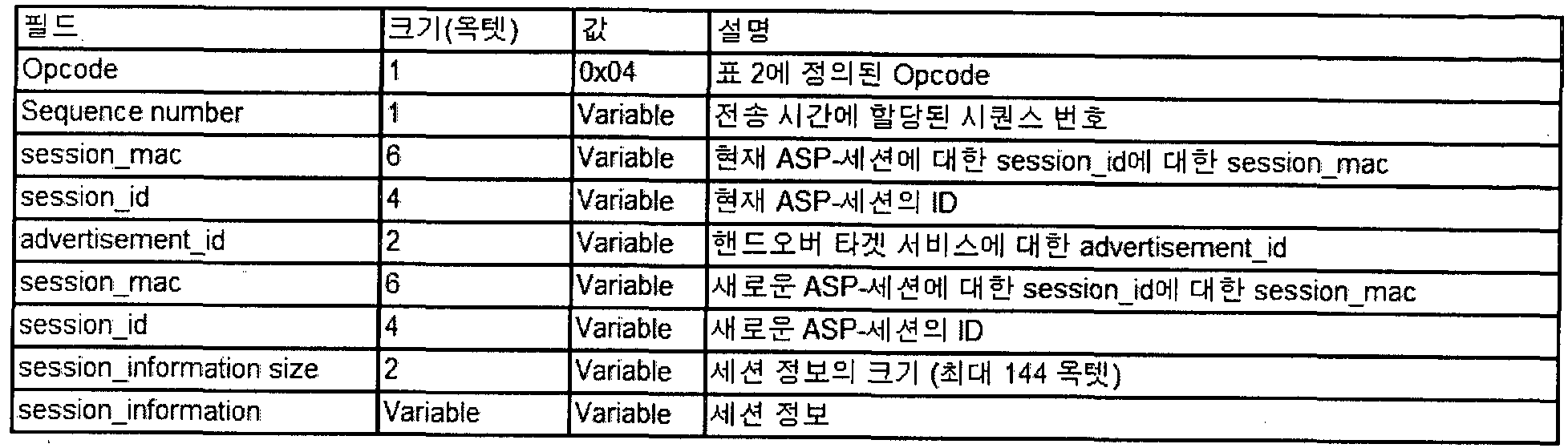
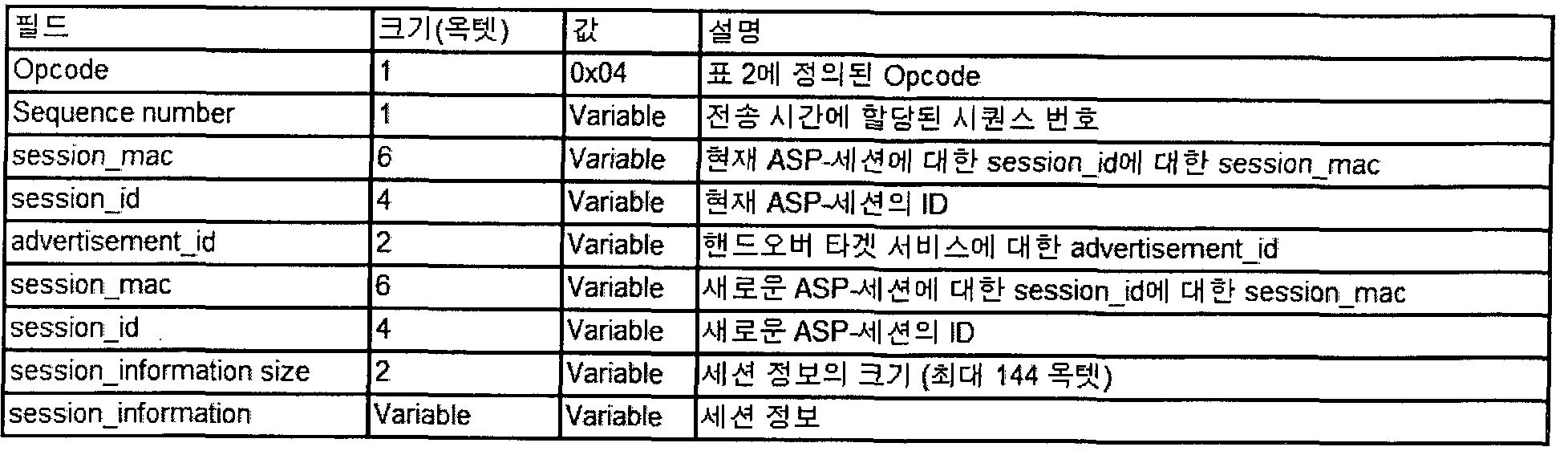
Claims
Priority Applications (7)
| Application Number | Priority Date | Filing Date | Title |
|---|---|---|---|
| JP2015551592A JP6294351B2 (ja) | 2013-01-03 | 2013-11-06 | 無線通信システムにおけるサービス転換方法及び装置 |
| CA2897007A CA2897007C (en) | 2013-01-03 | 2013-11-06 | Method and apparatus for changing services in wireless communication system |
| AU2013371719A AU2013371719B2 (en) | 2013-01-03 | 2013-11-06 | Method and apparatus for changing services in wireless communication system |
| CN201380074119.7A CN105027662B (zh) | 2013-01-03 | 2013-11-06 | 在无线通信系统中改变服务的方法和设备 |
| EP13870338.4A EP2943032B1 (en) | 2013-01-03 | 2013-11-06 | Method and apparatus for changing services in wireless communication system |
| KR1020157020370A KR101611329B1 (ko) | 2013-01-03 | 2013-11-06 | 무선 통신 시스템에서 서비스 전환 방법 및 장치 |
| US14/759,175 US9924552B2 (en) | 2013-01-03 | 2013-11-06 | Method and apparatus for changing in wireless communication system |
Applications Claiming Priority (8)
| Application Number | Priority Date | Filing Date | Title |
|---|---|---|---|
| US201361748449P | 2013-01-03 | 2013-01-03 | |
| US61/748,449 | 2013-01-03 | ||
| US201361759394P | 2013-01-31 | 2013-01-31 | |
| US61/759,394 | 2013-01-31 | ||
| US201361803807P | 2013-03-21 | 2013-03-21 | |
| US61/803,807 | 2013-03-21 | ||
| US201361804198P | 2013-03-22 | 2013-03-22 | |
| US61/804,198 | 2013-03-22 |
Publications (1)
| Publication Number | Publication Date |
|---|---|
| WO2014106990A1 true WO2014106990A1 (ko) | 2014-07-10 |
Family
ID=51062294
Family Applications (1)
| Application Number | Title | Priority Date | Filing Date |
|---|---|---|---|
| PCT/KR2013/010001 Ceased WO2014106990A1 (ko) | 2013-01-03 | 2013-11-06 | 무선 통신 시스템에서 서비스 전환 방법 및 장치 |
Country Status (8)
| Country | Link |
|---|---|
| US (1) | US9924552B2 (ko) |
| EP (1) | EP2943032B1 (ko) |
| JP (1) | JP6294351B2 (ko) |
| KR (1) | KR101611329B1 (ko) |
| CN (1) | CN105027662B (ko) |
| AU (1) | AU2013371719B2 (ko) |
| CA (1) | CA2897007C (ko) |
| WO (1) | WO2014106990A1 (ko) |
Cited By (4)
| Publication number | Priority date | Publication date | Assignee | Title |
|---|---|---|---|---|
| CN105451160A (zh) * | 2014-09-24 | 2016-03-30 | 三星电子株式会社 | 用于收发消息的方法、数据收发装置和非暂时性记录介质 |
| CN107005797A (zh) * | 2014-12-04 | 2017-08-01 | 高通股份有限公司 | 发现和管理针对无线显示系统中的多个宿的同步音频或视频流服务 |
| EP3346741A4 (en) * | 2015-09-02 | 2019-01-23 | LG Electronics Inc. | METHOD AND DEVICE FOR REPLACING CONNECTIVITY INFORMATION IN A WIRELESS COMMUNICATION SYSTEM |
| CN112911729A (zh) * | 2021-01-29 | 2021-06-04 | 成都极米科技股份有限公司 | 隧道直接链路建立的方法、终端及存储介质 |
Families Citing this family (25)
| Publication number | Priority date | Publication date | Assignee | Title |
|---|---|---|---|---|
| JP6216149B2 (ja) | 2013-04-26 | 2017-10-18 | キヤノン株式会社 | 通信装置、通信方法およびプログラム |
| JP6212280B2 (ja) * | 2013-04-26 | 2017-10-11 | キヤノン株式会社 | 通信装置、通信方法およびプログラム |
| US9635112B2 (en) * | 2013-05-02 | 2017-04-25 | Intel Corporation | Apparatus, system and method of managing an application service platform (ASP) session |
| US20140351445A1 (en) * | 2013-05-24 | 2014-11-27 | Qualcomm Incorporated | Mac layer transport for wi-fi direct services application service platform without internet protocol |
| US12309234B2 (en) * | 2014-05-30 | 2025-05-20 | Apple Inc. | System and method for transferring a call |
| US9992661B2 (en) * | 2014-09-24 | 2018-06-05 | Qualcomm Incorporated | Neighbor aware network logical channels |
| US10264441B2 (en) * | 2014-10-29 | 2019-04-16 | Lg Electronics Inc. | Method and apparatus for performing discovery by device supporting Wi-Fi Direct in wireless communication system |
| EP3026942B1 (en) * | 2014-11-28 | 2017-09-27 | Nokia Technologies OY | Discovery of neighbour peers and connection establisment for a peer to peer communication |
| US10098168B2 (en) * | 2014-12-08 | 2018-10-09 | Apple Inc. | Neighbor awareness networking datapath |
| US10827484B2 (en) | 2014-12-12 | 2020-11-03 | Qualcomm Incorporated | Traffic advertisement in neighbor aware network (NAN) data path |
| US10820314B2 (en) * | 2014-12-12 | 2020-10-27 | Qualcomm Incorporated | Traffic advertisement in neighbor aware network (NAN) data path |
| US10257667B2 (en) * | 2015-02-17 | 2019-04-09 | Huawei Technologies Co., Ltd. | Data transmission method and device |
| US10455401B2 (en) | 2015-02-24 | 2019-10-22 | Apple Inc. | Neighbor awareness networking datapath—reciprocation and coexistence |
| US10212574B2 (en) | 2015-03-20 | 2019-02-19 | Apple Inc. | Neighbor awareness networking datapath—base scheduling, scheduler rank, and further service discovery |
| US10893083B2 (en) | 2015-05-25 | 2021-01-12 | Apple Inc. | Neighbor awareness networking datapath—scheduling, scheduler rank, and pre-datapath operation triggering |
| JP6643848B2 (ja) * | 2015-09-24 | 2020-02-12 | キヤノン株式会社 | 通信装置、通信方法、およびプログラム |
| KR101685311B1 (ko) * | 2015-12-03 | 2016-12-20 | 충남대학교산학협력단 | 모바일 디바이스 간 연결상태에 따른 그룹 내 세션 관리방법 |
| JP6655968B2 (ja) * | 2015-12-03 | 2020-03-04 | キヤノン株式会社 | 通信装置、制御方法、及びプログラム |
| US10299302B2 (en) | 2016-03-01 | 2019-05-21 | Intel IP Corporation | Apparatus, system and method of peer-to-peer connection session setup |
| US10594785B2 (en) * | 2016-03-11 | 2020-03-17 | Intel Corporation | Transitioning from an infrastructure based wireless connection to a peer to peer (P2P) wireless connection |
| JP6752613B2 (ja) * | 2016-04-28 | 2020-09-09 | キヤノン株式会社 | 通信装置、通信方法及びプログラム |
| US10218797B2 (en) * | 2016-06-06 | 2019-02-26 | Intel IP Corporation | Communicating routing messages using service discovery in neighbor awareness networks |
| CN111866910B (zh) | 2019-09-18 | 2021-06-15 | 上海葡萄纬度科技有限公司 | 拼接积木的组网方法、系统及适用于无线组网的拼接积木 |
| CN114679732B (zh) * | 2020-12-24 | 2024-08-27 | 华为技术有限公司 | Wi-Fi直连下数据传输的方法和电子设备 |
| CN116647866A (zh) * | 2022-02-16 | 2023-08-25 | 极米科技股份有限公司 | 执行无线感知进程的方法、装置、设备及存储介质 |
Citations (5)
| Publication number | Priority date | Publication date | Assignee | Title |
|---|---|---|---|---|
| US20110149806A1 (en) * | 2009-12-22 | 2011-06-23 | Samsung Electronics Co., Ltd. | Method and apparatus for service discovery in wi-fi direct network |
| WO2012060611A2 (ko) * | 2010-11-03 | 2012-05-10 | 엘지전자 주식회사 | 장치 탐색 방법 및 그를 이용한 통신 장치 |
| KR20120103567A (ko) * | 2009-11-17 | 2012-09-19 | 삼성전자주식회사 | 와이파이 다이렉트 네트워크에서의 와이파이 디스플레이 서비스 탐색 방법 및 장치 |
| WO2012150815A2 (ko) * | 2011-05-02 | 2012-11-08 | 엘지전자 주식회사 | 무선 접속 시스템에서 장치 간 통신 수행 방법 및 이를 위한 장치 |
| WO2012173423A2 (ko) * | 2011-06-15 | 2012-12-20 | 엘지전자 주식회사 | 무선데이터통신장치 및 무선데이터통신방법 |
Family Cites Families (37)
| Publication number | Priority date | Publication date | Assignee | Title |
|---|---|---|---|---|
| EP1428348B1 (en) * | 2000-12-22 | 2011-01-26 | Research In Motion Limited | Information browser system and method for a wireless communication device |
| JP3967589B2 (ja) * | 2001-12-28 | 2007-08-29 | 富士通株式会社 | 広告配信方法及び広告配信装置 |
| US20080311899A1 (en) * | 2005-01-26 | 2008-12-18 | Sharp Kabushiki Kaisha | Mobile Communication Network Subscriber Information Management System, Subscriber Information Management Method, Communication Control Device, Communication Terminal Device, and Communication Control Method |
| US8705550B2 (en) * | 2005-08-08 | 2014-04-22 | Qualcomm Incorporated | Device interface architecture and protocol |
| JP5054699B2 (ja) * | 2005-10-20 | 2012-10-24 | シスコ テクノロジー インコーポレーテッド | ポリシ施行点インターフェース・システムおよび方法 |
| US20080019522A1 (en) * | 2006-06-21 | 2008-01-24 | Motorola, Inc. | Method For Managing A Communication Session in a Communication Network |
| JP4764279B2 (ja) * | 2006-07-28 | 2011-08-31 | 富士通株式会社 | 中継装置 |
| US9301121B2 (en) * | 2007-07-11 | 2016-03-29 | Qualcomm Incorporated | Peer to peer multiple identifiers |
| US8107953B2 (en) * | 2007-08-31 | 2012-01-31 | Tracfone Wireless, Inc. | System and method for activating services on a wireless device |
| US8719881B2 (en) * | 2008-02-25 | 2014-05-06 | Time Warner Cable Enterprises Llc | Methods and apparatus for enabling synchronized content presentations using dynamically updated playlists |
| US8626926B2 (en) * | 2008-02-26 | 2014-01-07 | Qualcomm Incorporated | Method and apparatus for performing session info query for user plane location |
| US8855087B2 (en) * | 2008-12-18 | 2014-10-07 | Microsoft Corporation | Wireless access point supporting control by multiple applications |
| US8627074B1 (en) * | 2009-05-12 | 2014-01-07 | Marvell International Ltd. | Secure block acknowledgement mechanism for use in communication networks |
| US8706124B2 (en) * | 2009-09-17 | 2014-04-22 | Nokia Corporation | Data path transfer for multiband communication |
| US9949305B2 (en) * | 2009-10-02 | 2018-04-17 | Blackberry Limited | Methods and apparatus for peer-to-peer communications in a wireless local area network |
| US20110082939A1 (en) * | 2009-10-02 | 2011-04-07 | Michael Peter Montemurro | Methods and apparatus to proxy discovery and negotiations between network entities to establish peer-to-peer communications |
| WO2011123763A1 (en) * | 2010-04-02 | 2011-10-06 | Interdigital Patend Holdings, Inc. | Inter ue transfer between mobile internet protocol clients |
| KR101640467B1 (ko) * | 2010-04-21 | 2016-07-18 | 삼성전자 주식회사 | 멀티모드 이동단말의 최대절전모드 제공 방법 및 장치 |
| KR101719161B1 (ko) * | 2010-05-13 | 2017-03-23 | 삼성전자주식회사 | WiFi 기반의 단말기 및 그의 채널 운용 방법 |
| KR101682385B1 (ko) | 2010-05-14 | 2016-12-05 | 삼성전자 주식회사 | 와이파이 디바이스의 와이파이 서비스 제공 방법 및 시스템 |
| US10250678B2 (en) * | 2010-07-07 | 2019-04-02 | Qualcomm Incorporated | Hybrid modes for peer discovery |
| US9270490B2 (en) * | 2010-10-22 | 2016-02-23 | Sabse Technologies, Inc. | Contextual presence system and associated methods |
| US9826404B2 (en) * | 2011-01-11 | 2017-11-21 | Qualcomm Incorporated | System and method for peer-to-peer authorization via non-access stratum procedures |
| US8554970B2 (en) * | 2011-04-18 | 2013-10-08 | Nokia Corporation | Method, apparatus and computer program product for creating a wireless docking group |
| GB2490968A (en) * | 2011-05-20 | 2012-11-21 | Nec Corp | Sharing radio access networks fairly between multiple operators |
| US8738442B1 (en) * | 2011-05-31 | 2014-05-27 | Google Inc. | System and mechanism for guaranteeing delivery order of virtual content |
| US9185595B2 (en) * | 2011-08-01 | 2015-11-10 | Telefonaktiebolaget L M Ericsson (Publ) | Method, apparatus and system for moving wireless terminals in mobility management serving node pool |
| CN104067686B (zh) * | 2012-01-12 | 2018-09-21 | 马维尔国际贸易有限公司 | 用于建立wi-fi显示(wfd)会话的系统和方法 |
| KR101849925B1 (ko) | 2012-02-24 | 2018-04-18 | 삼성전자주식회사 | 무선 통신 네트워크에서 디바이스 탐색 방법 및 장치 |
| US9609676B1 (en) * | 2012-03-30 | 2017-03-28 | Marvell International Ltd. | Efficient transition from discovery to link establishment |
| EP3496334B2 (en) * | 2012-04-27 | 2023-11-08 | InterDigital Patent Holdings, Inc. | Method and system for supporting proximity discovery procedures |
| WO2013169974A1 (en) * | 2012-05-11 | 2013-11-14 | Interdigital Patent Holdings, Inc. | Context-aware peer-to-peer communication |
| CN104429155A (zh) * | 2012-07-16 | 2015-03-18 | 三星电子株式会社 | 用于处理无线通信系统中的拓扑结构的方法和装置 |
| KR102037256B1 (ko) | 2012-08-08 | 2019-10-29 | 삼성전자주식회사 | 사용자 의향을 반영한 서비스 연결 장치 및 방법 |
| US9288754B2 (en) * | 2012-09-07 | 2016-03-15 | Qualcomm Incorporated | Apparatus and methods of power save for wireless access points and multi-hop relays |
| US9144094B2 (en) * | 2012-10-29 | 2015-09-22 | Qualcomm Incorporated | Establishing a wireless display session between a computing device and a vehicle head unit |
| US9064259B2 (en) * | 2012-12-19 | 2015-06-23 | Genesys Telecomminucations Laboratories, Inc. | Customer care mobile application |
-
2013
- 2013-11-06 AU AU2013371719A patent/AU2013371719B2/en active Active
- 2013-11-06 CN CN201380074119.7A patent/CN105027662B/zh active Active
- 2013-11-06 EP EP13870338.4A patent/EP2943032B1/en active Active
- 2013-11-06 CA CA2897007A patent/CA2897007C/en active Active
- 2013-11-06 WO PCT/KR2013/010001 patent/WO2014106990A1/ko not_active Ceased
- 2013-11-06 JP JP2015551592A patent/JP6294351B2/ja active Active
- 2013-11-06 KR KR1020157020370A patent/KR101611329B1/ko active Active
- 2013-11-06 US US14/759,175 patent/US9924552B2/en active Active
Patent Citations (5)
| Publication number | Priority date | Publication date | Assignee | Title |
|---|---|---|---|---|
| KR20120103567A (ko) * | 2009-11-17 | 2012-09-19 | 삼성전자주식회사 | 와이파이 다이렉트 네트워크에서의 와이파이 디스플레이 서비스 탐색 방법 및 장치 |
| US20110149806A1 (en) * | 2009-12-22 | 2011-06-23 | Samsung Electronics Co., Ltd. | Method and apparatus for service discovery in wi-fi direct network |
| WO2012060611A2 (ko) * | 2010-11-03 | 2012-05-10 | 엘지전자 주식회사 | 장치 탐색 방법 및 그를 이용한 통신 장치 |
| WO2012150815A2 (ko) * | 2011-05-02 | 2012-11-08 | 엘지전자 주식회사 | 무선 접속 시스템에서 장치 간 통신 수행 방법 및 이를 위한 장치 |
| WO2012173423A2 (ko) * | 2011-06-15 | 2012-12-20 | 엘지전자 주식회사 | 무선데이터통신장치 및 무선데이터통신방법 |
Cited By (6)
| Publication number | Priority date | Publication date | Assignee | Title |
|---|---|---|---|---|
| CN105451160A (zh) * | 2014-09-24 | 2016-03-30 | 三星电子株式会社 | 用于收发消息的方法、数据收发装置和非暂时性记录介质 |
| CN105451160B (zh) * | 2014-09-24 | 2020-12-11 | 三星电子株式会社 | 用于收发消息的方法、数据收发装置和非暂时性记录介质 |
| CN107005797A (zh) * | 2014-12-04 | 2017-08-01 | 高通股份有限公司 | 发现和管理针对无线显示系统中的多个宿的同步音频或视频流服务 |
| EP3346741A4 (en) * | 2015-09-02 | 2019-01-23 | LG Electronics Inc. | METHOD AND DEVICE FOR REPLACING CONNECTIVITY INFORMATION IN A WIRELESS COMMUNICATION SYSTEM |
| US10542410B2 (en) | 2015-09-02 | 2020-01-21 | Lg Electronics Inc. | Method and device for exchanging connection capability information in wireless communication system |
| CN112911729A (zh) * | 2021-01-29 | 2021-06-04 | 成都极米科技股份有限公司 | 隧道直接链路建立的方法、终端及存储介质 |
Also Published As
| Publication number | Publication date |
|---|---|
| KR20150112963A (ko) | 2015-10-07 |
| JP2016509398A (ja) | 2016-03-24 |
| CN105027662A (zh) | 2015-11-04 |
| KR101611329B1 (ko) | 2016-04-12 |
| EP2943032A4 (en) | 2016-01-27 |
| CA2897007C (en) | 2021-03-23 |
| US9924552B2 (en) | 2018-03-20 |
| EP2943032B1 (en) | 2018-01-03 |
| JP6294351B2 (ja) | 2018-03-14 |
| US20150351146A1 (en) | 2015-12-03 |
| AU2013371719A1 (en) | 2015-07-23 |
| CA2897007A1 (en) | 2014-07-10 |
| EP2943032A1 (en) | 2015-11-11 |
| AU2013371719B2 (en) | 2017-03-02 |
| CN105027662B (zh) | 2018-12-07 |
Similar Documents
| Publication | Publication Date | Title |
|---|---|---|
| KR101611329B1 (ko) | 무선 통신 시스템에서 서비스 전환 방법 및 장치 | |
| AU2013356802B2 (en) | Method and device for session initialization in wireless communication system | |
| JP6445549B2 (ja) | 直接通信システムにおけるデバイス探索方法及びそのための装置 | |
| KR102133846B1 (ko) | 직접 통신 시스템에서 피투피 그룹 형성 방법 및 이를 위한 장치 | |
| US9699715B2 (en) | Discovery method and device in a wireless communication system | |
| US9699819B2 (en) | Method and apparatus for establishing session in wireless communication system | |
| KR101829843B1 (ko) | 와이파이 디스플레이 서비스 수행 방법 및 이를 위한 장치 | |
| KR101779437B1 (ko) | 직접 통신 시스템에서 서비스 탐색 또는 광고 방법 및 이를 위한 장치 | |
| WO2014129844A1 (ko) | 와이파이 다이렉트(Wi- Fi Direct) P2P(Peer to Peer) 통신을 위한 기기 발견 방법 및 이를 위한 장치 | |
| US11611604B2 (en) | Method and apparatus for receiving streaming via transport protocol in wireless communication system | |
| JP2018524950A (ja) | 無線通信システムにおいてアプリケーションサービスプラットホームセッション形成方法及び装置 | |
| KR101801591B1 (ko) | 무선 통신 시스템에서 디스커버리를 수행하는 방법 및 장치 |
Legal Events
| Date | Code | Title | Description |
|---|---|---|---|
| WWE | Wipo information: entry into national phase |
Ref document number: 201380074119.7 Country of ref document: CN |
|
| 121 | Ep: the epo has been informed by wipo that ep was designated in this application |
Ref document number: 13870338 Country of ref document: EP Kind code of ref document: A1 |
|
| ENP | Entry into the national phase |
Ref document number: 2897007 Country of ref document: CA |
|
| WWE | Wipo information: entry into national phase |
Ref document number: 14759175 Country of ref document: US |
|
| ENP | Entry into the national phase |
Ref document number: 2015551592 Country of ref document: JP Kind code of ref document: A |
|
| NENP | Non-entry into the national phase |
Ref country code: DE |
|
| ENP | Entry into the national phase |
Ref document number: 2013371719 Country of ref document: AU Date of ref document: 20131106 Kind code of ref document: A |
|
| WWE | Wipo information: entry into national phase |
Ref document number: 1020157020370 Country of ref document: KR |
|
| WWE | Wipo information: entry into national phase |
Ref document number: 2013870338 Country of ref document: EP |