WO2014108953A1 - 紫外線殺菌装置 - Google Patents
紫外線殺菌装置 Download PDFInfo
- Publication number
- WO2014108953A1 WO2014108953A1 PCT/JP2013/006970 JP2013006970W WO2014108953A1 WO 2014108953 A1 WO2014108953 A1 WO 2014108953A1 JP 2013006970 W JP2013006970 W JP 2013006970W WO 2014108953 A1 WO2014108953 A1 WO 2014108953A1
- Authority
- WO
- WIPO (PCT)
- Prior art keywords
- ultraviolet
- plate
- sealed space
- outer peripheral
- transmitting plate
- Prior art date
- Legal status (The legal status is an assumption and is not a legal conclusion. Google has not performed a legal analysis and makes no representation as to the accuracy of the status listed.)
- Ceased
Links
Images


Classifications
-
- B—PERFORMING OPERATIONS; TRANSPORTING
- B65—CONVEYING; PACKING; STORING; HANDLING THIN OR FILAMENTARY MATERIAL
- B65B—MACHINES, APPARATUS OR DEVICES FOR, OR METHODS OF, PACKAGING ARTICLES OR MATERIALS; UNPACKING
- B65B55/00—Preserving, protecting or purifying packages or package contents in association with packaging
- B65B55/02—Sterilising, e.g. of complete packages
- B65B55/04—Sterilising wrappers or receptacles prior to, or during, packaging
- B65B55/08—Sterilising wrappers or receptacles prior to, or during, packaging by irradiation
-
- A—HUMAN NECESSITIES
- A61—MEDICAL OR VETERINARY SCIENCE; HYGIENE
- A61L—METHODS OR APPARATUS FOR STERILISING MATERIALS OR OBJECTS IN GENERAL; DISINFECTION, STERILISATION OR DEODORISATION OF AIR; CHEMICAL ASPECTS OF BANDAGES, DRESSINGS, ABSORBENT PADS OR SURGICAL ARTICLES; MATERIALS FOR BANDAGES, DRESSINGS, ABSORBENT PADS OR SURGICAL ARTICLES
- A61L2/00—Disinfection or sterilisation of materials or objects, in general; Accessories therefor
- A61L2/02—Disinfection or sterilisation of materials or objects, in general; Accessories therefor using physical processes
- A61L2/08—Radiation
- A61L2/10—Ultraviolet [UV] radiation
Definitions
- the present invention relates to an ultraviolet sterilizer that sterilizes food packaging materials by irradiating ultraviolet light (UV) through an ultraviolet transmissive plate, and more particularly to an ultraviolet sterilizer that can detect breakage of the ultraviolet transmissive plate. .
- UV ultraviolet light
- the high-pressure mercury type ultraviolet lamp has a problem that it has a short life because it is exposed to high heat, and has a problem that the transmittance of ultraviolet rays is greatly reduced as compared with the case of quartz glass alone.
- an ultraviolet transmissive plate such as a quartz glass plate is doubled in the lower opening of the housing, a sealed space is formed between these ultraviolet transmissive plates, and micro air is introduced into the sealed space or the sealed space.
- An object of the present invention is to provide an ultraviolet sterilizer capable of detecting a breakage of an ultraviolet transmission plate with higher accuracy while suppressing attenuation of ultraviolet rays by an ultraviolet transmission plate such as quartz glass.
- the present inventors have developed an ultraviolet sterilizer that can detect damage to an ultraviolet transmitting plate with higher accuracy while suppressing attenuation of ultraviolet rays by an ultraviolet transmitting plate such as quartz glass.
- an ultraviolet transmitting plate such as quartz glass.
- the ultraviolet ray transmitting plate is not disposed so as to be doubled so as to form a sealed space between the ultraviolet ray transmitting plates, but by forming a sealed space in the outer peripheral portion of one ultraviolet ray transmitting plate, It has been found that breakage of the ultraviolet transmission plate can be detected with higher accuracy while suppressing attenuation of ultraviolet rays by the transmission plate, and the present invention has been completed. That is, according to the present invention, since the ultraviolet ray transmitting plate can be single instead of being doubled, attenuation of ultraviolet rays by the ultraviolet ray transmitting plate can be suppressed, and a sealed space is formed on the outer periphery of the ultraviolet ray transmitting plate.
- the gauge pressure in the sealed space can be kept higher or lower while avoiding the possibility of damage to the ultraviolet transmitting plate, and as a result, when there is a fine crack due to some abnormality in the ultraviolet transmitting plate
- the amount of outflow or inflow of air in the sealed space increases, making it easy to detect the air flow in the sealed space with a flow meter, and detecting the breakage of the UV transmitting plate with higher accuracy.
- the present invention (1) an ultraviolet lamp; a housing that surrounds the ultraviolet lamp; an ultraviolet transmissive portion that is provided in a lower opening of the housing and includes an ultraviolet transmissive plate and a means for holding the ultraviolet transmissive plate; an air flow detecting means;
- the ultraviolet ray transmitting portion holding means has sealing means for forming a sealed space communicating with the air flow detecting means at one end in cooperation with an outer peripheral portion of the ultraviolet ray transmitting plate, and the air flow detecting means Is provided with an air pressure adjusting means and a flow meter for adjusting the air pressure in the sealed space, and the sealed space generated when the sealed state of the sealed space is released due to the damage of the ultraviolet transmitting plate.
- UV sterilizer characterized by detecting the flow of air with a flow meter, (2) The ultraviolet sterilizer according to (1) above, wherein the outer peripheral portion of the ultraviolet transmitting plate is an outer peripheral end surface or an outer peripheral edge of the ultraviolet transmitting plate, (3)
- the ultraviolet ray transmitting plate holding means includes a base plate fixed to the lower end of the side wall of the housing and a pressing plate fixed on the base plate.
- the sealing means is a means for directly sealing the outer base plate and the pressing plate on the outer peripheral end face of the ultraviolet transmitting plate and sealing the base plate and the pressing plate through the outer peripheral edge of the ultraviolet transmitting plate.
- the ultraviolet sterilizer according to (3) above, wherein the sealed space is formed along the outside of the outer peripheral end face of the ultraviolet transmissive plate, (5)
- the sealing means is means for sealing the base plate and the pressing plate through two predetermined intervals on the outer peripheral edge of the ultraviolet transmitting plate, and the sealed space is on the upper surface side of the outer peripheral edge of the ultraviolet transmitting plate.
- the ultraviolet sterilizer according to (3) characterized in that it is formed as a concave circumferential groove of a base plate corresponding to the pressing plate and / or the lower surface side, (6)
- the air pressure adjusting means is an air suction means for sucking air of a predetermined pressure from the sealed space and holding the sealed space in a negative pressure state.
- UV sterilizer according to any of the (8) The ultraviolet sterilizer according to any one of (1) to (7) above, wherein the ultraviolet transmitting plate is made of quartz glass.
- the present invention it is possible to form a sealed space in the outer peripheral portion of one ultraviolet transmitting plate instead of arranging the ultraviolet transmitting plates in a double manner and forming a sealed space between the ultraviolet transmitting plates.
- the gauge pressure in the sealed space can be kept higher or lower while avoiding the possibility of breakage of the transmission plate. As a result, even in the case where a minute crack occurs due to some abnormality in the ultraviolet transmission plate, The outflow amount or the inflow amount of air is increased, and the breakage of the ultraviolet transmitting plate can be detected with higher accuracy.
- the ultraviolet ray transmitting plate can be made single, the attenuation (illuminance loss) of the ultraviolet ray emitted from the ultraviolet lamp is reduced as compared with the case where the sealed space is formed by the double ultraviolet ray transmitting plate. In addition, the manufacturing cost can be reduced. Further, since the structure of the apparatus of the present invention is not so complicated, the present invention can be applied to various models at a low cost.
- FIG. 1 It is a schematic longitudinal cross-sectional view (front) of the ultraviolet sterilizer of this invention. It is an enlarged view of the part of A in FIG. It is the elements on larger scale of the ultraviolet sterilizer of this invention of another aspect.
- the ultraviolet sterilizer of the present invention includes: an ultraviolet lamp; a housing that surrounds the ultraviolet lamp; an ultraviolet transmissive portion that is provided in a lower opening of the housing and includes an ultraviolet transmissive plate and a means for holding the ultraviolet transmissive plate;
- the ultraviolet ray transmitting portion holding means has sealing means for forming a sealed space communicating with the air flow detecting means at one end in cooperation with the outer peripheral portion of the ultraviolet ray transmitting plate.
- the air flow detecting means includes an air pressure adjusting means for adjusting the air pressure in the sealed space and a flow meter, and when the sealed state of the sealed space is released due to breakage of the ultraviolet transmitting plate
- the outer peripheral edge and the outer peripheral edge of the overplate is the upper surface of the ultraviolet transmitting plate in the vicinity from the outer peripheral edge of the ultraviolet transmitting plate in a plan view (usually a region of 2 to 100 mm from the outer peripheral edge)
- region of a lower surface is said, and an outer peripheral end surface means the area
- the ultraviolet lamp a known ultraviolet lamp can be appropriately used in consideration of the ultraviolet transmittance of the ultraviolet transmitting portion, the necessary ultraviolet ray amount of the sterilization target, and the like.
- any UV lamp can be used regardless of the level of the vapor pressure in the lamp being lit, such as a low-pressure UV lamp, medium-pressure UV lamp, and high-pressure UV lamp.
- a high-pressure ultraviolet lamp such as a high-pressure mercury lamp or a metal halide lamp.
- the ultraviolet transmissive plate can be single, that is, a single sheet.
- the attenuation factor is low, it can be suitably used even with a low-pressure ultraviolet lamp or a medium-pressure ultraviolet lamp.
- a shape of the ultraviolet lamp used in the ultraviolet sterilization apparatus of the present invention from the viewpoint of securing a long sterilization time for the sterilization target to some extent, it is a long straight tube or an elongated U-shaped tube whose longitudinal direction is the movement direction of the sterilization target. It is preferable that the number thereof may be one or two or more.
- the housing is not particularly limited in shape and material as long as it encloses the ultraviolet lamp in the present invention and has an opening for the ultraviolet transmitting portion below, but for example, one of the six-sided rectangular parallelepiped shapes is ultraviolet-transmissive.
- the shape removed as the lower opening for the part can be suitably exemplified.
- the housing may be formed integrally with the holding means.
- the ultraviolet transmissive part disposed in the lower opening of the housing includes an ultraviolet transmissive plate and a means for holding the ultraviolet transmissive plate.
- the shape of the ultraviolet transmissive plate is not particularly limited, although it depends on the shape of the ultraviolet lamp, and is a plate shape such as a rectangle, square, circle or ellipse in a plan view, or a convex shape which can concentrate ultraviolet rays on the sterilization target. From the viewpoint of securing a long sterilization time for the sterilization target to some extent, the moving direction of the sterilization target is set to the longitudinal direction in accordance with the shape of the long linear tubular or long U-shaped ultraviolet lamp. A rectangular plate shape can be suitably exemplified.
- the thickness of the ultraviolet transmitting plate is not particularly limited as long as it can be sterilized by an ultraviolet lamp, but it is 0.5 to 15 mm in terms of the balance between the strength of the ultraviolet transmitting plate and the attenuation rate of ultraviolet rays by the ultraviolet transmitting plate. 2 to 7 mm is more preferable.
- the material of the ultraviolet ray transmitting plate is not particularly limited as long as it can transmit ultraviolet rays, but examples other than quartz glass include those described in JP-T-2005-519816 (Patent Document 3). Quartz glass is preferred because of its high transmittance.
- it is preferable to use one ultraviolet transmitting plate in the present invention it may be doubled as long as the attenuation rate of ultraviolet rays does not become too high.
- a sealed space can also be provided on the outer peripheral portion of the second ultraviolet transmitting plate, but it is not necessary to provide it.
- the ultraviolet transmissive plate can be held at its outer peripheral edge so as to irradiate the sterilization target by the ultraviolet lamp, and cooperates with the outer peripheral portion of the ultraviolet transmissive plate.
- the ultraviolet transmissive plate has a sealing means for forming a sealed space, and a concave groove for holding the outer peripheral edge of the UV transmitting plate is provided in three sides, and the UV transmitting plate is held from the other open end.
- a base plate lower holding plate
- a holding plate upper holding plate
- the base plate has an opening in the portion where the ultraviolet transmissive plate is arranged so that the ultraviolet lamp can irradiate the object to be sterilized, and the ultraviolet transmissive plate is held in cooperation with the holding plate at the opening edge.
- an opening edge portion on which the ultraviolet transmitting plate can be placed is formed in a concave step portion larger than the thickness of the ultraviolet transmitting plate.
- the opening has a shape substantially similar to the planar shape of the ultraviolet transmitting plate and smaller than the planar shape of the ultraviolet transmitting plate. A thing can be illustrated more suitably.
- the base plate opening may have an opening end at a position of 2 to 100 mm, preferably 5 to 50 mm inward from the outer peripheral end of the ultraviolet transmitting plate.
- an opening having an opening end at a position 30 mm inward from the outer peripheral end of a rectangular ultraviolet transmission plate 30 cm long and 60 cm wide becomes a rectangular shape having a length of 24 cm and a width of 54 cm.
- the holding plate has an opening in the portion where the ultraviolet transmissive plate is arranged so that the ultraviolet lamp can irradiate the object to be sterilized, and the ultraviolet transmissive plate is held in cooperation with the base plate at the opening edge.
- a preferable example is one that can press and hold the outer peripheral edge of the ultraviolet transmitting plate in cooperation with the base plate.
- a material that can press and hold the entire outer peripheral edge portion of the ultraviolet light transmitting plate in cooperation with the base plate can be more preferably exemplified.
- the holding plate opening can be exemplified by a shape that is substantially similar to the shape of the ultraviolet transmissive plate in plan view and smaller than the shape in plan view. Those having an opening end at a position of 2 to 100 mm, preferably 5 to 50 mm are preferable.
- a sealing agent such as a resin-based adhesive that can seal the opposing surfaces such as the base plate and the pressing plate directly or through an ultraviolet transmitting plate, or a holding means.
- a sealing agent such as a resin-based adhesive that can seal the opposing surfaces such as the base plate and the pressing plate directly or through an ultraviolet transmitting plate, or a holding means.
- an elastic body such as nitrile rubber, styrene rubber, silicone rubber, and fluorine rubber fitted into the concave circumferential groove are preferable, but sealing means using the elastic body is preferable for ease of assembly.
- the shape of the elastic body include an O-ring shape and a plate shape, and an O-ring-shaped elastic body (hereinafter referred to as an O-ring) is particularly preferable. In the case of using an O-ring, a better sealed state can be obtained if the diameter is slightly larger than the depth of the concave groove.
- FIGS. 1 and 2 A form (first sealing form; FIGS. 1 and 2) in which the base plate and the holding plate outside the outer peripheral end surface of the plate are directly sealed, and the base plate and the holding plate are sealed through the outer peripheral edge of the ultraviolet ray transmitting plate.
- the base plate and the pressing plate are sealed via two predetermined intervals on the upper surface side and the lower surface side of the outer peripheral edge portion of the ultraviolet transmitting plate, and the upper surface of the outer peripheral edge portion of the ultraviolet transmitting plate.
- the sealed space does not have to be formed over the entire circumference of the outer periphery of the UV transmitting plate, but from the viewpoint of detecting damage to the UV transmitting plate with higher accuracy, It is preferably formed in a tubular shape.
- One end of the sealed space is communicated with an air flow detection means through a port (opening) and a pipe.
- the port is a vacuum port when sucking air from the sealed space, and when air is introduced into the sealed space. Can be called a discharge port.
- the air flow detecting means is not particularly limited as long as it includes an air pressure adjusting means for adjusting the atmospheric pressure in the sealed space and a flow meter, and the air pressure adjusting means supplies air of a predetermined pressure to the sealed space.
- the sealed space can be held at a positive pressure or a negative pressure by introducing or sucking air of a predetermined pressure from the sealed space.
- air pressure adjusting means air supply means for introducing air of a predetermined pressure to keep the sealed space of the UV transmitting part in a positive pressure state, or sucking air to set the sealed space of the UV transmitting part in a negative pressure state.
- the air suction means (vacuum suction means) to be held in the container can be exemplified.
- the flow meter is provided in a pipe or the like between the air pressure adjusting means and the sealed space.
- the sealed space is sealed in accordance with the breakage of the ultraviolet transmitting plate. It is possible to detect the air flow in the sealed space that occurs when the state is released. It is preferable to arrange an electromagnetic valve that can open or close the pipe in the pipe between the air pressure adjusting means and the flow meter.
- an electromagnetic valve that can open or close the pipe in the pipe between the air pressure adjusting means and the flow meter.
- a regulator or a pressure switch that is preferably further arranged on the pipe is not necessary when the sealed space is held at a positive pressure.
- a regulator is a device for controlling the pressure supplied from the air supply means to a target pressure when the sealed space is held at a positive pressure, and the pressure switch is due to a malfunction of the regulator or the like. This is a switch for detecting an abnormal pressure and shutting off the air supply.
- Air means not only air but also all gases including inert gas.
- the gauge pressure in the sealed space (pressure notation with atmospheric pressure as the zero base point) can be set within a range of, for example, greater than 0 kPaG and less than or equal to 700 kPaG. From the viewpoint of detection with higher accuracy and from the viewpoint of safety of debris scattering due to positive pressure when the ultraviolet transmitting plate is broken, it is preferably in the range of 10 to 100 kPaG, and in the range of 10 to 50 kPaG. More preferred.
- the gauge pressure in the sealed space can be set within a range of, for example, less than 0 kPaG to ⁇ 101.3 kPaG, from the viewpoint of detecting the breakage of the ultraviolet transmission plate with higher accuracy. , Preferably in the range of ⁇ 50 to ⁇ 100 kPaG, more preferably in the range of ⁇ 90 to ⁇ 100 kPaG.
- the flow meter is not particularly limited as long as it can detect the air flow when the air flow is generated in the pipe.
- a flow meter having a minimum detection amount of about 0.05 to 0.5 L / min.
- the minimum detection flow rate is set so that detection can be performed when an air flow of 0.2 L / min or more occurs. It is preferable to do.
- a flow sensor flow sensor type flow meter
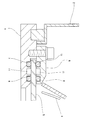
- FIG. 1 is a schematic cross-sectional view of the ultraviolet sterilizer of the present invention having the sealing means of the first embodiment
- FIG. 2 is an enlarged view of a portion A in FIG.
- FIG. 3 is the elements on larger scale of the ultraviolet sterilizer of this invention which has the sealing means of a 2nd aspect.
- the ultraviolet sterilizer of this type is provided in a U-tube type (single lamp type) ultraviolet lamp 3; a reflector 4; a housing 2 surrounding the ultraviolet lamp 3; and a lower opening of the housing 2.
- An ultraviolet transmitting part having a rectangular quartz glass 5 (ultraviolet transmitting plate) and a holding means for the quartz glass 5 provided with a base plate 1 and a pressing plate 6 fixed to the base plate 1 with screws; a vacuum pump (air Suction means), an air flow detecting means including a solenoid valve and a flow meter.
- the base plate 1 has a concave step for placing the quartz glass 5 and a quartz plate 5 at a substantially central portion than the quartz glass 5.
- quartz glass 5 When quartz glass 5 is placed on a horizontal surface of a concave step having a small similar rectangular opening, four surfaces of the outer peripheral end surface of the ultraviolet transmitting plate, the horizontal surface of the concave step, the vertical surface of the concave step, and the lower surface of the pressing plate 6 Tube composed of Enclosed space, i.e., in cooperation with the outer peripheral edge surface of the ultraviolet transmitting plate is configured along an outer peripheral end surface of ultraviolet transmitting plate, so that the tubular enclosed space communicating with the air flow detecting means is formed at one end.
- an O-ring 7 is provided between the pressing plate 6 and the base plate 1
- an O-ring 8 is provided between the pressing plate 6 and the ultraviolet transmission plate, and the base plate 1 and the ultraviolet transmission plate.
- the tubular sealed space communicates with the air flow detection means at one end via the vacuum port 10 and is formed when the sealed state of the tubular sealed space is released due to the breakage of the quartz glass 5.
- the air flow inside can be detected by a flow meter.
- the opening of the base plate 1 has an opening end at a position of 9.5 mm inward from the outer edge of the quartz glass 5, and the opening of the pressing plate 6 has an opening of 7 mm inward from the outer peripheral end of the quartz glass 5. Is the open end.
- the concave circumferential groove of the O-ring 7 is provided at a distance of about 3 mm from the outer peripheral end of the quartz glass 5, but can be provided at a distance of about 2.5 to 50 mm.
- the concave circumferential groove of the O-ring 9 is provided at a distance of about 2 mm from the outer peripheral end of the quartz glass 5, but may be provided at a distance of about 0.5 to 45 mm.
- the container is sterilized by the ultraviolet sterilizer (type I) of the present invention, for example, as follows. While the gable top type packaging container C is opened in the longitudinal direction with the upper part opened, ultraviolet rays irradiated from the ultraviolet lamp 3 (for example, a low-pressure mercury lamp) are large in size. A high illuminance is maintained by the reflecting plate 4, and the bottom of the packaging container C can be reliably irradiated and sterilized.
- the ultraviolet sterilizer (type I) of the present invention for example, as follows. While the gable top type packaging container C is opened in the longitudinal direction with the upper part opened, ultraviolet irradiated from the ultraviolet lamp 3 (for example, a low-pressure mercury lamp) are large in size. A high illuminance is maintained by the reflecting plate 4, and the bottom of the packaging container C can be reliably irradiated and sterilized.
- the ultraviolet lamp 3 for example, a low-pressure mercury lamp
- the ultraviolet sterilizer when the electromagnetic valve is opened, the air in the tubular sealed space 11 is sucked into the vacuum pump via the vacuum port 10 and the piping, and the sealed space 11 is maintained at a predetermined negative pressure. While the sealed state of the tubular sealed space 11 is maintained, there is no air flow in the pipe. However, when a part of the quartz glass 5 is broken, air flows into the tubular sealed space 11 and the pipe is closed. An air flow is generated in the air flow meter, and the flow meter detects the air flow.
- the quartz glass 5 is held in a state where there is a degree of freedom in which the quartz glass 5 is sandwiched between the O-rings, that is, in a state where the ultraviolet transmitting plate is not in direct contact with the pressing plate and the base plate. Even if it is a breakage such as a fine crack, the quartz glass 5 is deformed and cracks reach the end of the quartz glass 5 and air flows into the tubular sealed space. This is detected by the flow meter, whereby the breakage of the quartz glass 5 can be detected with higher accuracy.
- FIG. 3 shows a partially enlarged view of the ultraviolet sterilizer (type II) of the present invention.
- the base plate 1 and the holding plate 6 each have a substantially rectangular opening smaller than the quartz glass 5 in the substantially central portion, and the opening edge of the base plate 1 and the holding plate 6, that is, the outer peripheral edge of the ultraviolet transmitting plate.
- the concave circumferential grooves of the O-rings 7 and 13 and the concave circumferential grooves of the O-rings 9 and 8 are provided with the sealed space 11 in between.
- the opening of the base plate 1 has an opening end at a position of 19.5 mm inward from the outer edge of the quartz glass 5, and the opening of the holding plate 6 has an opening of 17 mm inward from the outer peripheral end of the quartz glass 5. Is the open end.
- the concave circumferential grooves of the O-rings 7 and 13 are provided at a distance of about 2 mm from the outer peripheral end of the quartz glass 5, and the concave circumferential grooves of the O-rings 9 and 8 are about 12 mm from the outer peripheral end of the quartz glass 5. They are spaced apart.
- the ultraviolet sterilizer of the present invention can be used, for example, to sterilize food packaging containers and the like.
Landscapes
- Health & Medical Sciences (AREA)
- General Health & Medical Sciences (AREA)
- Epidemiology (AREA)
- Life Sciences & Earth Sciences (AREA)
- Animal Behavior & Ethology (AREA)
- Public Health (AREA)
- Veterinary Medicine (AREA)
- Toxicology (AREA)
- Engineering & Computer Science (AREA)
- Mechanical Engineering (AREA)
- Apparatus For Disinfection Or Sterilisation (AREA)
Abstract
石英ガラス等の紫外線透過板による紫外線の減衰を抑えつつ、紫外線透過板の破損をより高い精度で検出することができる紫外線殺菌装置を提供することを課題とする。 紫外線ランプと;該紫外線ランプを包囲するハウジングと;該ハウジングの下方開口部に設けられ、紫外線透過板と紫外線透過板の保持手段とを有する紫外線透過部と;エアー流検出手段と;を備え、前記紫外線透過部の保持手段は、一端において前記エアー流検出手段に連通する密閉空間を、紫外線透過板の外周部と協働して形成する密封手段を有し、前記エアー流検出手段は、密閉空間内の気圧を調整するためのエアー圧調整手段とフローメータとを備えた紫外線殺菌装置であって、紫外線透過板の破損に伴い前記密閉空間の密封状態が解放されたときに生じる密閉空間内のエアーの流れをフローメータにより検出する。
Description
本発明は、紫外線(UV)を紫外線透過板を介して食品包装材料等に照射することにより殺菌する紫外線殺菌装置、より詳しくは、前記紫外線透過板の破損を検出することができる紫外線殺菌装置に関する。
食品業界においては、賞味期限の延長等を目的として、紫外線ランプ装置を用いた殺菌方法が用いられている。かかる紫外線ランプ装置においては、ハウジング内に設けられたランプと外部とを遮断するために、一般に、特定の波長の紫外線(254nm)を透過する石英ガラスが使用されている。他方、産業界全体においては、近年、製造者責任の観点より様々な面で安全性への要求が増加し、ガラスの破損による異物混入の恐れがあるとしてガラス製品の使用さえ許可されないケースもでてきているが、現状では、紫外線ランプ装置の機能を満足すべく石英ガラスの使用が強く求められており、何らかの安全性確保の方策が必要とされている。
[規則91に基づく訂正 14.03.2014]
上記のような背景の中、石英ガラス製の紫外線透過板の破損の検出方法としていくつかの方法が提案されているが、いずれも一長一短があり、更なる改良と差別化が求められている。例えば、ハウジング内部を冷却用ガスにより中圧(約0.1MPa)に保持し、圧力の低下を検出することにより、石英ガラスの割れを監視する方法が提案されている(特許文献1参照)。しかしながら、この方法では、小さな破損(ヒビ割れ)の検出には限界があり、また、ランプ交換等のメンテナンス作業が必要なハウジング自体を密閉とするため、パッキン類の隙間からリークする場合もあり、どこからリークしているのか発見するのが困難であり、確実に石英ガラスの破損を検出できるというものではなかった。
上記のような背景の中、石英ガラス製の紫外線透過板の破損の検出方法としていくつかの方法が提案されているが、いずれも一長一短があり、更なる改良と差別化が求められている。例えば、ハウジング内部を冷却用ガスにより中圧(約0.1MPa)に保持し、圧力の低下を検出することにより、石英ガラスの割れを監視する方法が提案されている(特許文献1参照)。しかしながら、この方法では、小さな破損(ヒビ割れ)の検出には限界があり、また、ランプ交換等のメンテナンス作業が必要なハウジング自体を密閉とするため、パッキン類の隙間からリークする場合もあり、どこからリークしているのか発見するのが困難であり、確実に石英ガラスの破損を検出できるというものではなかった。
また、石英ガラス端部(紫外線の有効部分以外の部分)に配線を特殊な樹脂にて接着し、その線に通電を行ない、ガラス破損時に断線を検出する方法も提案されているが(特許文献2参照)、高圧殺菌装置においては実績がなく、また、電気線が完全に断裂しないと検出できず、ひび割れ位置や破損程度によっては、石英ガラスの割れを検出できない場合もあり、確実性が低いものであった。また、石英ガラス全面を網羅して配線することは、非常に困難であり、現実的でない。
さらに、テフロン(登録商標)系の特殊ポリマーフィルムを石英ガラスの下側に配置し、石英ガラスやUVランプの破損時の異物落下を防止する方法も提案されているが(特許文献3参照)、高圧水銀タイプの紫外線ランプにおいては、高熱に曝されるため寿命が短く、また、紫外線の透過性が石英ガラス単体の場合に比して大きく低下するという問題があった。
また、ハウジングの下方開口部に、石英ガラス板等の紫外線透過板を2重に配置して、これらの紫外線透過板の間に密閉空間を形成し、該密閉空間に微圧エアーを導入又は該密閉空間からエアーを吸引して、フローセンサによりエアーの流れを検出することにより、紫外線透過板の破損を検出する方法も提案されているが(特許文献4参照)、照射された紫外線は紫外線透過板を2重に透過しなければならず、減衰率は1重の場合の約2倍になってしまう。紫外線力の強い高圧水銀ランプを採用すればこの問題をクリアできるとも考えられるが、高圧水銀ランプの価格は低圧水銀ランプの約2~2.5倍と高く、コスト面で不利があった。一方、コストが安価な低圧水銀ランプを用いた場合、かかるランプは紫外線力が相対的に弱いため、そのランプの寿命の末期近くには、所定の殺菌効果を得ることができないという問題があった。さらに、この特許文献4の方法では、紫外線透過板の間の密閉空間のゲージ圧力(正圧又は負圧)を高くし過ぎると、紫外線透過板が破損するおそれがあるという問題もあった。
本発明の課題は、石英ガラス等の紫外線透過板による紫外線の減衰を抑えつつ、紫外線透過板の破損をより高い精度で検出することができる紫外線殺菌装置を提供することにある。
本発明者らは、背景技術に記載したような状況下、石英ガラス等の紫外線透過板による紫外線の減衰を抑えつつ、紫外線透過板の破損をより高い精度で検出することができる紫外線殺菌装置を得るべく鋭意検討を行い、石英ガラス等の紫外線透過板ではわずかな割れでもそれが紫外線透過板の端部にまで到達することに着目し、さらに鋭意検討を重ねた結果、特許文献4記載の装置のように、紫外線透過板を2重になるように配置して該紫外線透過板の間に密閉空間を形成するのではなく、1枚の紫外線透過板の外周部に密閉空間を形成することによって、紫外線透過板による紫外線の減衰を抑えつつ、紫外線透過板の破損をより高い精度で検出することができることを見いだし、本発明を完成するに至った。すなわち、本発明によると、紫外線透過板は2重ではなく1重にすることができるため、紫外線透過板による紫外線の減衰を抑えることができ、また、紫外線透過板の外周部に密閉空間を形成することにより、紫外線透過板の破損のおそれを回避しながら密閉空間のゲージ圧力をより高く、あるいはより低く保つことができ、その結果、紫外線透過板において何らかの異常により微細なヒビ割れが生じた場合でも密閉空間におけるエアーの流出量又は流入量が多くなって、該密閉空間内のエアーの流れをフローメータにより検出しやすくなり、紫外線透過板の破損をより高い精度で検出し得ることを見いだした。
すなわち、本発明は、
(1)紫外線ランプと;該紫外線ランプを包囲するハウジングと;該ハウジングの下方開口部に設けられ、紫外線透過板と紫外線透過板の保持手段とを有する紫外線透過部と;エアー流検出手段と;を備え、前記紫外線透過部の保持手段は、一端において前記エアー流検出手段に連通する密閉空間を、紫外線透過板の外周部と協働して形成する密封手段を有し、前記エアー流検出手段は、密閉空間内の気圧を調整するためのエアー圧調整手段とフローメータとを備えており、前記紫外線透過板の破損に伴い前記密閉空間の密封状態が解放されたときに生じる密閉空間内のエアーの流れをフローメータにより検出することを特徴とする紫外線殺菌装置や、
(2)紫外線透過板の外周部が、紫外線透過板の外周端面又は外周縁部であることを特徴とする上記(1)に記載の紫外線殺菌装置や、
(3)紫外線透過板の保持手段が、ハウジングの側壁下端に固定されているベース板と、該ベース板上に固定されている押さえ板とを備えていることを特徴とする上記(1)又は(2)に記載の紫外線殺菌装置や、
(4)密封手段が、紫外線透過板の外周端面の外方のベース板と押さえ板とを直接密封すると共に、紫外線透過板の外周縁部を介してベース板と押さえ板とを密封する手段であり、密閉空間が紫外線透過板の外周端面の外側に沿って形成されることを特徴とする上記(3)に記載の紫外線殺菌装置や、
(5)密封手段が、紫外線透過板の外周縁部の所定の間隔の2ヶ所を介してベース板と押さえ板とを密封する手段であり、密閉空間が紫外線透過板の外周縁部の上面側に相当する押さえ板及び/又は下面側に相当するベース板の凹状周溝として形成されることを特徴とする上記(3)に記載の紫外線殺菌装置や、
(6)密封手段がOリング形状の弾性体であることを特徴とする上記(1)~(5)のいずれかに記載の紫外線殺菌装置や、
(7)エアー圧調整手段が、密閉空間から所定圧のエアーを吸引して、該密閉空間を負圧状態に保持するエアー吸引手段であることを特徴とする上記(1)~(6)のいずれかに記載の紫外線殺菌装置や、
(8)紫外線透過板が、石英ガラスであることを特徴とする上記(1)~(7)のいずれかに記載の紫外線殺菌装置に関する。
(1)紫外線ランプと;該紫外線ランプを包囲するハウジングと;該ハウジングの下方開口部に設けられ、紫外線透過板と紫外線透過板の保持手段とを有する紫外線透過部と;エアー流検出手段と;を備え、前記紫外線透過部の保持手段は、一端において前記エアー流検出手段に連通する密閉空間を、紫外線透過板の外周部と協働して形成する密封手段を有し、前記エアー流検出手段は、密閉空間内の気圧を調整するためのエアー圧調整手段とフローメータとを備えており、前記紫外線透過板の破損に伴い前記密閉空間の密封状態が解放されたときに生じる密閉空間内のエアーの流れをフローメータにより検出することを特徴とする紫外線殺菌装置や、
(2)紫外線透過板の外周部が、紫外線透過板の外周端面又は外周縁部であることを特徴とする上記(1)に記載の紫外線殺菌装置や、
(3)紫外線透過板の保持手段が、ハウジングの側壁下端に固定されているベース板と、該ベース板上に固定されている押さえ板とを備えていることを特徴とする上記(1)又は(2)に記載の紫外線殺菌装置や、
(4)密封手段が、紫外線透過板の外周端面の外方のベース板と押さえ板とを直接密封すると共に、紫外線透過板の外周縁部を介してベース板と押さえ板とを密封する手段であり、密閉空間が紫外線透過板の外周端面の外側に沿って形成されることを特徴とする上記(3)に記載の紫外線殺菌装置や、
(5)密封手段が、紫外線透過板の外周縁部の所定の間隔の2ヶ所を介してベース板と押さえ板とを密封する手段であり、密閉空間が紫外線透過板の外周縁部の上面側に相当する押さえ板及び/又は下面側に相当するベース板の凹状周溝として形成されることを特徴とする上記(3)に記載の紫外線殺菌装置や、
(6)密封手段がOリング形状の弾性体であることを特徴とする上記(1)~(5)のいずれかに記載の紫外線殺菌装置や、
(7)エアー圧調整手段が、密閉空間から所定圧のエアーを吸引して、該密閉空間を負圧状態に保持するエアー吸引手段であることを特徴とする上記(1)~(6)のいずれかに記載の紫外線殺菌装置や、
(8)紫外線透過板が、石英ガラスであることを特徴とする上記(1)~(7)のいずれかに記載の紫外線殺菌装置に関する。
本発明によると、紫外線透過板を2重に配置して該紫外線透過板の間に密閉空間を形成するのではなく、1枚の紫外線透過板の外周部に密閉空間を形成することができるため、紫外線透過板の破損が生じるおそれを回避しながら密閉空間のゲージ圧力をより高く、あるいはより低く保つことができ、その結果、紫外線透過板において何らかの異常により微細なヒビ割れが生じた場合でも密閉空間におけるエアーの流出量又は流入量が多くなって、紫外線透過板の破損をより高い精度で検出することができる。また、本発明によると、紫外線透過板は1重にすることができるため、2重の紫外線透過板で密閉空間を形成する場合と比較して、紫外線ランプが発する紫外線の減衰(照度ロス)を抑制することができ、また、製造コストも抑えることができる。また、本発明の装置の構造自体はそれほど複雑ではないため、本発明は様々な機種に低コストで適用することができる。
本発明の紫外線殺菌装置としては、紫外線ランプと;該紫外線ランプを包囲するハウジングと;該ハウジングの下方開口部に設けられ、紫外線透過板と紫外線透過板の保持手段とを有する紫外線透過部と;エアー流検出手段と;を備え、前記紫外線透過部の保持手段は、一端において前記エアー流検出手段に連通する密閉空間を、紫外線透過板の外周部と協働して形成する密封手段を有し、前記エアー流検出手段は、密閉空間内の気圧を調整するためのエアー圧調整手段とフローメータとを備えており、前記紫外線透過板の破損に伴い前記密閉空間の密封状態が解放されたときに生じる密閉空間内のエアーの流れをフローメータにより検出する紫外線殺菌装置であれば特に制限されるものではなく、上記紫外線透過板の外周部とは、紫外線透過板の外周縁部と外周端面との総称であり、外周縁部とは、平面視した紫外線透過板の外周端から近傍(通常、外周端から2~100mmの領域)の紫外線透過板の上面及び/又は下面の領域をいい、外周端面とは、側面視した紫外線透過板の2つの外周端の間の領域(側周面)をいう。
上記紫外線ランプとしては、紫外線透過部の紫外線透過度や殺菌対象物の必要紫外線量等を考慮して、適宜公知の紫外線ランプを使用することができる。具体的には、低圧紫外線ランプ、中圧紫外線ランプ、高圧紫外線ランプ等、点灯中のランプ内の蒸気の圧力の高低にかかわらず、いずれの紫外線ランプをも用いることができ、より高い殺菌効果を得たい場合には、高圧水銀ランプ、メタルハライドランプ等の高圧紫外線ランプを用いることが好ましいが、本発明の紫外線殺菌装置では、紫外線透過板を1重、すなわち1枚とすることができ、紫外線の減衰率が低いため、低圧紫外線ランプや中圧紫外線ランプでも好適に使用することができる。また、本発明の紫外線殺菌装置に用いる紫外線ランプの形状としては、殺菌対象の殺菌時間をある程度長く確保する観点から、殺菌対象の移動方向を長手方向とする長い直線管状や細長いU字管状とすることが好ましく、またその個数は、1個であってもよいし、2個以上であってもよい。また、紫外線ランプの紫外線をより効率的に殺菌対象に照射する観点から、紫外線ランプの近くに反射板を設けることが好ましい。
上記ハウジングとしては、本発明における紫外線ランプを包囲し、下方に紫外線透過部のための開口部を有する限り、形状、材質等特に制限されないが、例えば六面の直方体形状のうち、一面を紫外線透過部用の下方開口部として取り除いた形状を好適に例示することができる。また、上記ハウジングは、上記保持手段と一体化して形成されていてもよい。
ハウジングの下方開口部に配置される紫外線透過部は、紫外線透過板と紫外線透過板の保持手段とを備えている。紫外線透過板の形状としては、紫外線ランプの形状に依存するものの特に制限されず、平面視で長方形、正方形、円形、楕円形等の板状や、紫外線を殺菌対象に集中させることができる凸面状を好適に例示することができ、殺菌対象の殺菌時間をある程度長く確保する観点から、前記長い直線管状や長いU字管状の紫外線ランプの形状に合わせて、殺菌対象の移動方向を長手方向とする長方形の板状を好適に例示することができる。紫外線透過板の厚さとしては、紫外線ランプによる殺菌が可能である限り特に制限されないが、紫外線透過板の強度と、該紫外線透過板による紫外線の減衰率とのバランスの点で0.5~15mmが好ましく、2~7mmがより好ましい。紫外線透過板の材質としては、紫外線を透過できるものであれば特に制限されないが、石英ガラスの他に特表2005-519816号公報(特許文献3)記載のもの等を例示することができ、紫外線透過度が高い点から、石英ガラスが好ましい。なお、本発明における紫外線透過板は1枚とすることが好ましいが、紫外線の減衰率が高くなりすぎない範囲で2重にしてもよい。2枚目の紫外線透過板の外周部にも密閉空間を設けることができるが、設けなくともよい。
上記紫外線透過板の保持手段としては、上記紫外線ランプにより殺菌対象を照射し得るように、紫外線透過板をその外周縁部で保持することができ、かつ、紫外線透過板の外周部と協働して密閉空間を形成する密封手段を有していれば特に制限されず、その三方に紫外線透過板の外周縁部を挟持するための凹状溝が設けられ、他の開放端から紫外線透過板を挟持用凹状溝にスライドさせて挿着しうる一体成形型の保持手段でもよいが、組み立てやメンテナンスのしやすさから紫外線透過板を挟持しうるベース板(下部保持板)と押さえ板(上部保持板)の組み合わせからなる保持手段を好適に例示することができる。
上記ベース板としては、紫外線ランプが殺菌対象を照射し得るように、紫外線透過板を配置する部分に開口部を有し、その開口縁部で紫外線透過板を押さえ板と協働して保持しうるものを例示することができ、紫外線透過板の厚みより大きい凹状の段差部分に紫外線透過板を載置しうる開口縁部が形成されているものを好適に例示することができる。また、紫外線透過板の落下の危険性を回避する観点から、紫外線透過板の平面視形状と略相似形状であって、紫外線透過板の平面視形状よりも小さい形状の開口部を有しているものをより好適に例示することができる。上記ベース板開口部は、紫外線透過板の外周端から内側へ2~100mm、好ましくは5~50mmの位置を開口端とすることができる。例えば、平面視したときに縦30cm横60cmの長方形状の紫外線透過板の外周端から内側へ30mmの位置を開口端とする開口部は、縦24cm横54cmの長方形状となる。
上記押さえ板としては、紫外線ランプが殺菌対象を照射し得るように、紫外線透過板を配置する部分に開口部を有し、その開口縁部で紫外線透過板をベース板と協働して保持しうるものであれば特に制限されないが、より優れた密封状態の密閉空間を得る観点から、紫外線透過板の外周縁部をベース板と協働して押圧・保持しうるものを好適に例示することができ、中でも、紫外線透過板の全外周縁部をベース板と協働して押圧・保持しうるものをより好適に例示することができる。上記押さえ板開口部は、紫外線透過板の平面視形状と略相似形状であって、平面視形状よりも小さい形状のものをより好適に例示することができ、中でも、紫外線透過板の外縁から内側へ2~100mm、好ましくは5~50mmの位置を開口端とするものが好ましい。
上記保持手段に設けられた密封手段としては、ベース板や押さえ板等の対向する面を直接又は紫外線透過板を介して密封することができる、樹脂系接着剤等のシール剤や、保持手段に設けられた凹状周溝と該凹状周溝に嵌入するニトリルゴム、スチロールゴム、シリコーンゴム、フッ素ゴム等の弾性体を例示することができるが、組み立てやすさから弾性体を利用した密封手段が好ましく、弾性体の形状としては、Oリング状や板状を挙げることができるが、Oリング状の弾性体(以下、Oリングという)が特に好ましい。Oリングを用いる場合、その径が凹状溝部の深さよりも少し大きいものを用いると、より優れた密封状態を得ることができる。
[規則91に基づく訂正 14.03.2014]
ベース板と押さえ板の組み合わせからなる保持手段における密封形態としては、紫外線透過板の外周端面と協働して密閉空間を紫外線透過板の外周端面に沿ってその外側に形成するための、紫外線透過板の外周端面の外方のベース板と押さえ板とを直接密封すると共に、紫外線透過板の外周縁部を介してベース板と押さえ板とを密封する形態(第1密封形態;図1及び2参照)や、紫外線透過板の外周縁部の上面及び下面と協働して密閉空間を紫外線透過板の外周縁部の上面側に相当する押さえ板及び/又は下面側に相当するベース板の凹状周溝として形成するための、紫外線透過板の外周縁部の上面側及び/又は下面側の所定の間隔の2ヶ所を介してベース板と押さえ板とを密封する形態(第2密封形態)を挙げることができる。
ベース板と押さえ板の組み合わせからなる保持手段における密封形態としては、紫外線透過板の外周端面と協働して密閉空間を紫外線透過板の外周端面に沿ってその外側に形成するための、紫外線透過板の外周端面の外方のベース板と押さえ板とを直接密封すると共に、紫外線透過板の外周縁部を介してベース板と押さえ板とを密封する形態(第1密封形態;図1及び2参照)や、紫外線透過板の外周縁部の上面及び下面と協働して密閉空間を紫外線透過板の外周縁部の上面側に相当する押さえ板及び/又は下面側に相当するベース板の凹状周溝として形成するための、紫外線透過板の外周縁部の上面側及び/又は下面側の所定の間隔の2ヶ所を介してベース板と押さえ板とを密封する形態(第2密封形態)を挙げることができる。
上記第2密封形態においては、紫外線透過板の外周縁部の上面側及び下面側の所定の間隔の2ヶ所を介してベース板と押さえ板とを密封し、紫外線透過板の外周縁部の上面側に相当する押さえ板及び下面側に相当するベース板の2ヶ所の密封手段の間に挟まれた上下2つの凹状周溝からなる密閉空間を形成する形態(図3参照)や、紫外線透過板の外周縁部の上面側又は下面側の所定の間隔の2ヶ所を介してベース板と押さえ板とを密封し、紫外線透過板の外周縁部の上面側に相当する押さえ板又は下面側に相当するベース板の2ヶ所の密封手段の間に挟まれた1つの凹状周溝からなる密閉空間を形成する形態を例示することができるが、この1つの凹状周溝からなる密閉空間を形成する場合、凹状周溝からなる密閉空間を形成しない方のベース板や押さえ板の対向面には、例えば2つのOリングを用いてもよいが、1つの板状ゴムを用いることもできる。
上記紫外線透過板の外周端面の外側に沿って形成される密閉空間や、紫外線透過板の外周縁部の上面側に相当する押さえ板及び/又は下面側に相当するベース板の凹状周溝として形成される密閉空間は、紫外線透過板の外周部の全周にわたり形成されていなくてもよいが、紫外線透過板の破損をより高精度で検出する観点から、紫外線透過板の外周部の全周に管状に形成されていることが好ましい。かかる密閉空間の一端は、ポート(開口部)及び配管にてエアー流検出手段に連通されており、かかるポートは、密閉空間からエアーを吸引する場合はバキュームポート、密閉空間にエアーを導入する場合はディスチャージポートと呼ぶことができる。
上記エアー流検出手段は、密閉空間内の気圧を調整するためのエアー圧調整手段とフローメータとを備えている限り特に制限されず、かかるエアー圧調整手段は、密閉空間に所定圧のエアーを導入、又は該密閉空間から所定圧のエアーを吸引して、該密閉空間を正圧又は負圧に保持することができる。上記のエアー圧調整手段としては、所定圧のエアーを導入して紫外線透過部の密閉空間を正圧状態に保持するエアー供給手段や、エアーを吸引して紫外線透過部の密閉空間を負圧状態に保持するエアー吸引手段(真空吸引手段)を例示することができる。
上記フローメータは、エアー圧調整手段と上記密閉空間との間の配管等に設けられており、かかる配管内のエアーの流れを検出することで、紫外線透過板の破損に伴い前記密閉空間の密封状態が解放されたときに生じる密閉空間内のエアーの流れを検出できる。エアー圧調整手段とフローメータの間の配管には、配管を開放又は閉鎖し得る電磁弁を配置することが好ましい。密閉空間を負圧状態に保持する場合は、紫外線透過板の破損片が殺菌対象物側に飛び散ることを抑制することができる点で有利である。また、密閉空間を負圧に保持する場合は、正圧に保持する場合に上記配管にさらに配置することが好ましいレギュレータや圧力スイッチが不要となる点でも好ましい。なお、かかるレギュレータは、密閉空間を正圧に保持する場合に、エアー供給手段から供給される圧力を制御して目的とする圧力とするための装置であり、圧力スイッチは、レギュレータの不具合等による圧力異常を検知してエアー供給を遮断するためのスイッチである。レギュレータを配管に設置する場合は、エアー圧調整手段とフローメータとの間に設置することが好ましく、さらに電磁弁を併用する場合は、レギュレータをエアー圧調整手段と電磁弁との間の設置することが好ましい。圧力スイッチを配管に設置する場合は、エアー圧調整手段とフローメータとの間に設置することが好ましく、さらにレギュレータを併用する場合は、レギュレータとフローメータとの間に設置することが好ましく、また、レギュレータと電磁弁を併用する場合は、エアー圧調整手段、レギュレータ、電磁弁、圧力スイッチ、フローメータの順に設置することが好ましい。なお、エアーとは、空気のみならず、不活性ガス等を含む気体全般を意味する。
密閉空間を正圧状態とする場合、密閉空間におけるゲージ圧力(大気圧を0基点とする圧力標記)を、例えば0kPaGより大きく700kPaG以下の範囲内とすることができるが、紫外線透過板の破損をより高い精度で検出する観点や、紫外線透過板が破損したときに正圧による破片の飛び散りの安全面から、10~100kPaGの範囲内とすることが好ましく、10~50kPaGの範囲内とすることがより好ましい。一方、密閉空間を負圧状態とする場合、密閉空間のゲージ圧力を、例えば0kPaG未満から-101.3kPaGの範囲内とすることができ、紫外線透過板の破損をより高い精度で検出する観点から、-50~-100kPaGの範囲内とすることが好ましく、-90~-100kPaGの範囲内とすることがより好ましい。
上記フローメータ(流量計)としては、上記配管内にエアーの流れが生じた場合にかかるエアーの流れを検出することができるものであれば特に制限されるものではないが、微量のエアーの流れを検出できるフローメータであることが好ましく、例えば、最小検出量が0.05~0.5L/min程度のフローメータを用いることが好ましい。具体的には、例えば、最小検出流量が0.2L/minのフローメータを用いる場合、かかる最小検出流量に設定し、0.2L/min以上のエアーの流れが生じた場合に検知できるようにすることが好ましい。かかる高感度なフローメータとして、フローセンサ(フローセンサ式のフローメータ)を好適に例示することができる。
以下、図面を参照しつつ本発明の装置を説明するが、本発明はこれに限定されるものではない。図1は、第1態様の密封手段を有している本発明の紫外線殺菌装置の概略断面図であり、図2は図1中のAの部分の拡大図である。また、図3は、第2態様の密封手段を有する本発明の紫外線殺菌装置の部分拡大図である。
図1及び図2に本発明の紫外線殺菌装置(タイプI)を示す。このタイプの紫外線殺菌装置は、U字管式(1灯式)の紫外線ランプ3と;反射板4と;紫外線ランプ3を包囲するハウジング2と;ハウジング2の下方開口部に設けられ、平面視長方形の石英ガラス5(紫外線透過板)と、ベース板1及び該ベース板1にネジで固着される押さえ板6を備えた石英ガラス5の保持手段とを有する紫外線透過部と;バキュームポンプ(エアー吸引手段)と電磁弁とフローメータとを備えたエアー流検出手段と;を備え、上記ベース板1は、石英ガラス5を載置するための凹状段差と、略中央部に石英ガラス5よりも小さい相似長方形の開口を有し、凹状段差の水平面上に石英ガラス5を載置したときに、紫外線透過板の外周端面と凹状段差の水平面と凹状段差の垂直面と押さえ板6下面の4面で構成される管状密閉空間、すなわち、紫外線透過板の外周端面と協働して紫外線透過板の外周端面の外側に沿って構成され、一端においてエアー流検出手段に連通する管状密閉空間が形成されることになる。また、かかる密閉空間の密封性を高めるために、押さえ板6とベース板1との間にOリング7、押さえ板6と紫外線透過板との間にOリング8、ベース板1と紫外線透過板との間にOリング9がそれぞれ挟持されている。かかる管状密閉空間は、一端において前記エアー流検出手段にバキュームポート10を経由して連通しており、石英ガラス5の破損に伴い上記管状密閉空間の密封状態が解放されたときに生じる管状密閉空間内のエアーの流れをフローメータにより検出することができる。
かかる紫外線殺菌装置において、ベース板1の開口部は、石英ガラス5の外縁から内側へ9.5mmの位置を開口端とし、押さえ板6の開口部は、石英ガラス5の外周端から内側へ7mmの位置を開口端としている。また、Oリング7の凹状周溝は、石英ガラス5の外周端から3mm程度離間して設けられているが、2.5~50mm程度離間して設けることもできる。Oリング9の凹状周溝は、石英ガラス5の外周端から2mm程度離間して設けられているが、0.5~45mm程度離間して設けることもできる。
本発明の紫外線殺菌装置(タイプI)による容器の殺菌は、例えば以下のように行われる。ゲーブルトップ型の包装容器Cがその上部を開放した状態で、紫外線ランプ3の下方をその長手方向に搬送されている間に、紫外線ランプ3(例えば低圧水銀灯)から照射された紫外線は、大型の反射板4によって高い照度を維持し、包装容器Cの底部まで確実に照射して殺菌できるようになっている。
上記紫外線殺菌装置において、電磁弁を開放すると管状密閉空間11内のエアーがバキュームポート10及び配管を経由してバキュームポンプに吸引され、密閉空間11内は所定の負圧状態に保持される。管状密閉空間11の密閉状態が保持されている間は、配管内にエアーの流れはないが、石英ガラス5の一部が破損した場合には、管状密閉空間11にエアーが流入すると共に配管内にエアーの流れが生じ、フローメータがこのエアーの流れを検知する。かかる本発明の装置によれば、石英ガラス5がOリングに挟まれた自由度のある状態、すなわち、紫外線透過板が押さえ板及びベース板に直接接触していない状態で保持されているため、微細なヒビ割れ等の破損であっても石英ガラス5に変形が生じ石英ガラス5の端部にまでヒビが到達し、管状密閉空間内にエアーが流入し、かかるエアーの流れが配管内のエアーの流れを生じさせ、これをフローメータが検出し、それによって、石英ガラス5の破損をより高い精度で検出することができる。
図3に本発明の紫外線殺菌装置(タイプII)の部分拡大図を示す。ベース板1及び押さえ板6は、それぞれ略中央部に石英ガラス5よりも小さい相似長方形の開口部を有し、ベース板1及び押さえ板6の開口縁部、すなわち、紫外線透過板の外周縁部の下面側に相当するベース板及び上面側に相当する押さえ板に、それぞれOリング7,13の凹状周溝とOリング9,8の凹状周溝が密閉空間11を挟んで設けられている。
かかる紫外線殺菌装置において、ベース板1の開口部は、石英ガラス5の外縁から内側へ19.5mmの位置を開口端とし、押さえ板6の開口部は、石英ガラス5の外周端から内側へ17mmの位置を開口端としている。また、Oリング7,13の凹状周溝は、石英ガラス5の外周端から2mm程度離間して設けられており、Oリング9,8の凹状周溝は、石英ガラス5の外周端から12mm程度離間して設けられている。
本発明の紫外線殺菌装置は、例えば、食品包装容器等を殺菌するために用いることができる。
1 ベース板
2 ハウジング
3 紫外線ランプ
4 反射板
5 石英ガラス
6 押さえ板
7 Oリング
8 Oリング
9 Oリング
10 バキュームポート
11 管状密閉空間
12 紫外線殺菌装置
13 Oリング(第4環状弾性体)
C 包装容器
2 ハウジング
3 紫外線ランプ
4 反射板
5 石英ガラス
6 押さえ板
7 Oリング
8 Oリング
9 Oリング
10 バキュームポート
11 管状密閉空間
12 紫外線殺菌装置
13 Oリング(第4環状弾性体)
C 包装容器
Claims (8)
- 紫外線ランプと;該紫外線ランプを包囲するハウジングと;該ハウジングの下方開口部に設けられ、紫外線透過板と紫外線透過板の保持手段とを有する紫外線透過部と;エアー流検出手段と;を備え、
前記紫外線透過部の保持手段は、一端において前記エアー流検出手段に連通する密閉空間を、紫外線透過板の外周部と協働して形成する密封手段を有し、
前記エアー流検出手段は、密閉空間内の気圧を調整するためのエアー圧調整手段とフローメータとを備えており、
前記紫外線透過板の破損に伴い前記密閉空間の密封状態が解放されたときに生じる密閉空間内のエアーの流れをフローメータにより検出する
ことを特徴とする紫外線殺菌装置。 - 紫外線透過板の外周部が、紫外線透過板の外周端面又は外周縁部であることを特徴とする請求項1記載の紫外線殺菌装置。
- 紫外線透過板の保持手段が、ハウジングの側壁下端に固定されているベース板と、該ベース板上に固定されている押さえ板とを備えていることを特徴とする請求項1又は2記載の紫外線殺菌装置。
- 密封手段が、紫外線透過板の外周端面の外方のベース板と押さえ板とを直接密封すると共に、紫外線透過板の外周縁部を介してベース板と押さえ板とを密封する手段であり、密閉空間が紫外線透過板の外周端面の外側に沿って形成されることを特徴とする請求項3記載の紫外線殺菌装置。
- 密封手段が、紫外線透過板の外周縁部の所定の間隔の2ヶ所を介してベース板と押さえ板とを密封する手段であり、密閉空間が紫外線透過板の外周縁部の上面側に相当する押さえ板及び/又は下面側に相当するベース板の凹状周溝として形成されることを特徴とする請求項3記載の紫外線殺菌装置。
- 密封手段がOリング形状の弾性体であることを特徴とする請求項1~5のいずれかに記載の紫外線殺菌装置。
- エアー圧調整手段が、密閉空間から所定圧のエアーを吸引して、該密閉空間を負圧状態に保持するエアー吸引手段であることを特徴とする請求項1~6のいずれかに記載の紫外線殺菌装置。
- 紫外線透過板が、石英ガラスであることを特徴とする請求項1~7のいずれかに記載の紫外線殺菌装置。
Priority Applications (3)
| Application Number | Priority Date | Filing Date | Title |
|---|---|---|---|
| NO13871055A NO2944327T3 (ja) | 2013-01-10 | 2013-11-27 | |
| EP13871055.3A EP2944327B1 (en) | 2013-01-10 | 2013-11-27 | Ultraviolet sterilizer |
| DK13871055.3T DK2944327T3 (da) | 2013-01-10 | 2013-11-27 | Ultraviolet sterilisator |
Applications Claiming Priority (2)
| Application Number | Priority Date | Filing Date | Title |
|---|---|---|---|
| JP2013-002942 | 2013-01-10 | ||
| JP2013002942A JP5968795B2 (ja) | 2013-01-10 | 2013-01-10 | 紫外線殺菌装置 |
Publications (1)
| Publication Number | Publication Date |
|---|---|
| WO2014108953A1 true WO2014108953A1 (ja) | 2014-07-17 |
Family
ID=51166633
Family Applications (1)
| Application Number | Title | Priority Date | Filing Date |
|---|---|---|---|
| PCT/JP2013/006970 Ceased WO2014108953A1 (ja) | 2013-01-10 | 2013-11-27 | 紫外線殺菌装置 |
Country Status (5)
| Country | Link |
|---|---|
| EP (1) | EP2944327B1 (ja) |
| JP (1) | JP5968795B2 (ja) |
| DK (1) | DK2944327T3 (ja) |
| NO (1) | NO2944327T3 (ja) |
| WO (1) | WO2014108953A1 (ja) |
Cited By (3)
| Publication number | Priority date | Publication date | Assignee | Title |
|---|---|---|---|---|
| WO2016207057A1 (en) * | 2015-06-22 | 2016-12-29 | Tetra Laval Holdings & Finance S.A. | Arrangement and method for packaging a liquid consumable product in a package |
| CN110234581A (zh) * | 2017-09-26 | 2019-09-13 | 首尔伟傲世有限公司 | 便携式水杯 |
| US12486067B2 (en) | 2022-04-21 | 2025-12-02 | Tetra Laval Holdings & Finance S.A. | Method for packaging a food product and a packaging machine |
Families Citing this family (9)
| Publication number | Priority date | Publication date | Assignee | Title |
|---|---|---|---|---|
| JP6645009B2 (ja) * | 2015-01-07 | 2020-02-12 | 岩崎電気株式会社 | 紫外線硬化処理システム |
| CN110859976B (zh) | 2015-06-26 | 2022-10-04 | 首尔伟傲世有限公司 | 杀菌器及杀菌系统 |
| CN106924772A (zh) * | 2015-12-30 | 2017-07-07 | 博西华电器(江苏)有限公司 | 消毒柜 |
| CN110740758B (zh) | 2017-07-07 | 2022-10-11 | 首尔伟傲世有限公司 | 杀菌模块 |
| CN109935376B (zh) * | 2017-12-18 | 2022-06-28 | 中国核动力研究设计院 | 一种核电厂严重事故下β射线对仪表损伤的量化方法 |
| GB2583522B (en) * | 2019-05-02 | 2022-05-18 | Xylem Europe Gmbh | A breakage detection device for a UV disinfection system |
| JP7315899B2 (ja) * | 2019-12-25 | 2023-07-27 | ウシオ電機株式会社 | 紫外線照射装置 |
| CN115394898A (zh) * | 2021-05-25 | 2022-11-25 | 佛山市国星光电股份有限公司 | 一种紫外led器件及其制备方法 |
| KR102473488B1 (ko) * | 2022-05-20 | 2022-12-01 | 서경아 | Uv led 어셈블리 및 이를 장착한 정수기 |
Citations (6)
| Publication number | Priority date | Publication date | Assignee | Title |
|---|---|---|---|---|
| JPH0242642U (ja) * | 1988-09-14 | 1990-03-23 | ||
| JP2000506822A (ja) * | 1996-10-23 | 2000-06-06 | テトラ ラバル ホールデイングス エ フイナンス ソシエテ アノニム | 紫外線照射によってカートンを滅菌するための方法および装置 |
| JP2001097319A (ja) | 1999-07-29 | 2001-04-10 | Heraeus Noblelight Gmbh | 食品処理のための照射装置 |
| JP2005519816A (ja) | 2002-03-12 | 2005-07-07 | テトラ ラバル ホールデイングス エ フイナンス ソシエテ アノニム | Uv放射線によって包装材料を処理する装置 |
| JP2008500303A (ja) * | 2004-05-27 | 2008-01-10 | バクスター・インターナショナル・インコーポレイテッド | ホルマリンおよびuv光での処理によるサンプル中の病原体の不活化 |
| JP2012085850A (ja) | 2010-10-20 | 2012-05-10 | Shikoku Kakoki Co Ltd | 紫外線殺菌装置 |
Family Cites Families (5)
| Publication number | Priority date | Publication date | Assignee | Title |
|---|---|---|---|---|
| JPH0513736Y2 (ja) * | 1987-01-29 | 1993-04-12 | ||
| US5400223A (en) * | 1993-07-14 | 1995-03-21 | General Electric Company | Sports lighting luminaire having a broken glass safety shutdown circuit |
| EP1721684A3 (de) * | 2005-05-09 | 2008-07-30 | Liconic Ag | Nutzraum mit in-situ-Entkeimungsvorrichtung |
| WO2007046213A1 (ja) * | 2005-10-18 | 2007-04-26 | Japan Ae Power Systems Corporation | 電子線照射方法、電子線照射装置および開口容器用電子線照射装置 |
| JP5575078B2 (ja) * | 2011-09-15 | 2014-08-20 | 株式会社東芝 | 紫外線照射装置 |
-
2013
- 2013-01-10 JP JP2013002942A patent/JP5968795B2/ja active Active
- 2013-11-27 EP EP13871055.3A patent/EP2944327B1/en active Active
- 2013-11-27 DK DK13871055.3T patent/DK2944327T3/da active
- 2013-11-27 NO NO13871055A patent/NO2944327T3/no unknown
- 2013-11-27 WO PCT/JP2013/006970 patent/WO2014108953A1/ja not_active Ceased
Patent Citations (7)
| Publication number | Priority date | Publication date | Assignee | Title |
|---|---|---|---|---|
| JPH0242642U (ja) * | 1988-09-14 | 1990-03-23 | ||
| JP2000506822A (ja) * | 1996-10-23 | 2000-06-06 | テトラ ラバル ホールデイングス エ フイナンス ソシエテ アノニム | 紫外線照射によってカートンを滅菌するための方法および装置 |
| JP3963480B2 (ja) | 1996-10-23 | 2007-08-22 | テトラ ラバル ホールデイングス エ フイナンス ソシエテ アノニム | 紫外線照射によってカートンを滅菌するための方法および装置 |
| JP2001097319A (ja) | 1999-07-29 | 2001-04-10 | Heraeus Noblelight Gmbh | 食品処理のための照射装置 |
| JP2005519816A (ja) | 2002-03-12 | 2005-07-07 | テトラ ラバル ホールデイングス エ フイナンス ソシエテ アノニム | Uv放射線によって包装材料を処理する装置 |
| JP2008500303A (ja) * | 2004-05-27 | 2008-01-10 | バクスター・インターナショナル・インコーポレイテッド | ホルマリンおよびuv光での処理によるサンプル中の病原体の不活化 |
| JP2012085850A (ja) | 2010-10-20 | 2012-05-10 | Shikoku Kakoki Co Ltd | 紫外線殺菌装置 |
Cited By (7)
| Publication number | Priority date | Publication date | Assignee | Title |
|---|---|---|---|---|
| WO2016207057A1 (en) * | 2015-06-22 | 2016-12-29 | Tetra Laval Holdings & Finance S.A. | Arrangement and method for packaging a liquid consumable product in a package |
| CN107624100A (zh) * | 2015-06-22 | 2018-01-23 | 利乐拉瓦尔集团及财务有限公司 | 用于将液体消耗品包装在包装件中的装置和方法 |
| CN110234581A (zh) * | 2017-09-26 | 2019-09-13 | 首尔伟傲世有限公司 | 便携式水杯 |
| US11396459B2 (en) | 2017-09-26 | 2022-07-26 | Seoul Viosys Co., Ltd. | Portable water bottle having a UV light sterilization module |
| US11753315B2 (en) | 2017-09-26 | 2023-09-12 | Seoul Viosys Co., Ltd. | Portable water bottle having a UV light sterilization module |
| US12351488B2 (en) | 2017-09-26 | 2025-07-08 | Seoul Viosys Co., Ltd. | Portable water bottle having a UV light sterilization module |
| US12486067B2 (en) | 2022-04-21 | 2025-12-02 | Tetra Laval Holdings & Finance S.A. | Method for packaging a food product and a packaging machine |
Also Published As
| Publication number | Publication date |
|---|---|
| DK2944327T3 (da) | 2017-11-27 |
| JP2014133007A (ja) | 2014-07-24 |
| EP2944327A4 (en) | 2016-09-21 |
| EP2944327A1 (en) | 2015-11-18 |
| NO2944327T3 (ja) | 2018-01-27 |
| EP2944327B1 (en) | 2017-08-30 |
| JP5968795B2 (ja) | 2016-08-10 |
Similar Documents
| Publication | Publication Date | Title |
|---|---|---|
| JP5968795B2 (ja) | 紫外線殺菌装置 | |
| JP6142797B2 (ja) | 光照射装置 | |
| CN101370537B (zh) | 确定医疗耗材内流体压力的压力测量单元 | |
| KR101906746B1 (ko) | 가압 유체 살균 장치 | |
| CN110384808B (zh) | 紫外线照射装置 | |
| TWI752180B (zh) | 具有光學感測器之真空閥 | |
| CN211141587U (zh) | 流体杀菌装置 | |
| JP5885699B2 (ja) | 脆性破壊性光透過窓板の固定構造及びこれを用いた脆性破壊性光透過窓板の固定方法 | |
| US9402927B2 (en) | Device for sterilization by ultraviolet radiation | |
| US10654729B2 (en) | Fluid sterilization device | |
| CN111684204B (zh) | 紫外灯模块及其用途 | |
| JP2021041382A (ja) | 流体殺菌装置 | |
| JP2010197386A (ja) | インライン高圧粒子検知システム | |
| CN101551269B (zh) | 光传感器 | |
| JP5596492B2 (ja) | 紫外線殺菌装置 | |
| JP2021062369A (ja) | 紫外線照射装置 | |
| KR101774145B1 (ko) | 가스 누설 감지 장치 | |
| JP2015119127A (ja) | 光照射装置 | |
| JP6850763B2 (ja) | 流体殺菌モジュール | |
| JP6699472B2 (ja) | 液体処理装置 | |
| JP7299034B2 (ja) | 紫外線照射装置 | |
| CN211141588U (zh) | 流体杀菌装置 | |
| KR101692738B1 (ko) | 가스누설 차단이 가능한 가스배관 오염도 모니터링 장치 | |
| JP2024071025A (ja) | 紫外線照射装置 | |
| KR200315022Y1 (ko) | 자외선 살균장치 |
Legal Events
| Date | Code | Title | Description |
|---|---|---|---|
| 121 | Ep: the epo has been informed by wipo that ep was designated in this application |
Ref document number: 13871055 Country of ref document: EP Kind code of ref document: A1 |
|
| REEP | Request for entry into the european phase |
Ref document number: 2013871055 Country of ref document: EP |
|
| WWE | Wipo information: entry into national phase |
Ref document number: 2013871055 Country of ref document: EP |
|
| NENP | Non-entry into the national phase |
Ref country code: DE |