WO2014108961A1 - 空気入りタイヤ - Google Patents
空気入りタイヤ Download PDFInfo
- Publication number
- WO2014108961A1 WO2014108961A1 PCT/JP2013/007376 JP2013007376W WO2014108961A1 WO 2014108961 A1 WO2014108961 A1 WO 2014108961A1 JP 2013007376 W JP2013007376 W JP 2013007376W WO 2014108961 A1 WO2014108961 A1 WO 2014108961A1
- Authority
- WO
- WIPO (PCT)
- Prior art keywords
- tire
- decorative
- radial direction
- tire radial
- line
- Prior art date
- Legal status (The legal status is an assumption and is not a legal conclusion. Google has not performed a legal analysis and makes no representation as to the accuracy of the status listed.)
- Ceased
Links
Images

Classifications
-
- B—PERFORMING OPERATIONS; TRANSPORTING
- B60—VEHICLES IN GENERAL
- B60C—VEHICLE TYRES; TYRE INFLATION; TYRE CHANGING; CONNECTING VALVES TO INFLATABLE ELASTIC BODIES IN GENERAL; DEVICES OR ARRANGEMENTS RELATED TO TYRES
- B60C13/00—Tyre sidewalls; Protecting, decorating, marking, or the like, thereof
- B60C13/001—Decorating, marking or the like
-
- B—PERFORMING OPERATIONS; TRANSPORTING
- B60—VEHICLES IN GENERAL
- B60C—VEHICLE TYRES; TYRE INFLATION; TYRE CHANGING; CONNECTING VALVES TO INFLATABLE ELASTIC BODIES IN GENERAL; DEVICES OR ARRANGEMENTS RELATED TO TYRES
- B60C13/00—Tyre sidewalls; Protecting, decorating, marking, or the like, thereof
- B60C13/04—Tyre sidewalls; Protecting, decorating, marking, or the like, thereof having annular inlays or covers, e.g. white sidewalls
-
- B—PERFORMING OPERATIONS; TRANSPORTING
- B60—VEHICLES IN GENERAL
- B60C—VEHICLE TYRES; TYRE INFLATION; TYRE CHANGING; CONNECTING VALVES TO INFLATABLE ELASTIC BODIES IN GENERAL; DEVICES OR ARRANGEMENTS RELATED TO TYRES
- B60C5/00—Inflatable pneumatic tyres or inner tubes
Definitions
- the present invention relates to a pneumatic tire in which a decorative band having a smooth surface is formed on a sidewall portion.
- Patent Document 1 a pneumatic tire having a decorative band (color line) formed by printing, painting, sealing, sticker or the like on a sidewall portion has been proposed. According to this pneumatic tire, it is possible to increase the rim diameter while suppressing an increase in unsprung weight.
- An object of the present invention is to effectively solve such a problem, and an object of the present invention is to provide a pneumatic tire capable of suppressing a decrease in tire rolling resistance and showing a large rim diameter. .
- the pneumatic tire according to the present invention is a pneumatic tire in which a decorative band having a smooth surface is formed on a sidewall portion, and the outermost end in the tire radial direction of the decorative band is smaller than the tire maximum width position.
- the decorative strip is located on the inner side of the tire, and the decorative strip includes a plurality of decorative lines extending in the tire circumferential direction and having a lightness higher than the tire ground color, and the decorative line having the highest lightness among the decorative lines has a lightness of 80%.
- brightness and / or hue are different from those of at least one other decoration line.
- the position and size of the outermost end of the decorative band in the tire radial direction and the like are measured with an unloaded tire that is assembled to the applicable rim and filled with the specified internal pressure.
- the “applied rim” is an industrial standard effective in the region where the tire is produced or used. For example, in the United States, “THE TIRE AND RIM ASSOCIATION INC.” “YEAR BOOK”, in Europe “ The standard rim (or “Approved Rimde”, “Reprobed Rimde”, or “Approved Rimde” in the applicable sizes described in “STANDARDDS MANUAL” of The European Tire and Rim Technical Organization, “JATMA YEAR BOOK” of “Japan Automobile Tire Association” in Japan, etc. ).
- specified internal pressure refers to the air pressure specified in accordance with the maximum load capacity in the above standard
- maximum load capacity refers to the load applied to the tire in the above standard for the applicable size (ply rating). The maximum mass allowed to be done.
- the “tire maximum width position” is a character of a sidewall portion in an unloaded state in which a tire is assembled to the above-mentioned applicable rim and filled with the maximum air pressure defined by the above standard.
- the lightness is an index representing the brightness of the color, with 100% lightness being the brightest color in each hue and 0% lightness being true black.
- the saturation is an index indicating the purity of the color in a range of 0 to 100%. A color with high saturation is a pure color, and a color with low saturation is a dull color.
- the hue is an index indicating where the color is in the spectrum in the range of 0 to 360 degrees, where 0 degree is red, and yellow, green, cyan, blue, and magenta every 60 degrees.
- the brightness, saturation, and hue are measured using a spectrocolorimeter (for example, manufactured by Konica Minolta Co., Ltd.) after measuring the brightness of a measurement object such as a decorative band in another system (for example, a Lab color space). It shall be measured by a method of converting into an HSV system using necessary software (for example, photoshop (registered trademark)).
- a spectrocolorimeter for example, manufactured by Konica Minolta Co., Ltd.
- necessary software for example, photoshop (registered trademark)
- the pneumatic tire of the present invention a decrease in tire rolling resistance can be suppressed, and the rim diameter can be made larger without a sense of incongruity compared with the conventional tire.
- FIG. 1 is a cross-sectional view in the width direction of a tire half portion illustrating a pneumatic tire according to an embodiment of the present invention in an unloaded state in which a pneumatic tire is assembled to an applied rim and filled with a predetermined internal pressure. It is a side view of the tire shown in FIG. FIG. 3 is an enlarged view of a main part of FIG. 2. It is a side view similar to FIG. 2 which shows the pneumatic tire of other embodiment of this invention. It is a principal part enlarged view of FIG.
- the pneumatic tire illustrated in FIG. 1 includes a pair of bead portions 1 in which a bead core 4 is embedded, a pair of sidewall portions 2 extending outward in the tire radial direction from the bead portion 1, and a tread portion extending between both sidewall portions. 3 is provided.
- the pneumatic tire also includes a toroidal carcass ply 6 straddling the pair of bead cores 4.
- an annular decorative band 10 extending in the tire circumferential direction is formed on the inner side in the tire radial direction from the tire maximum width position Pw of the sidewall portion 2.
- the width of the decorative band 10 in the tire radial direction can be set to, for example, 8 mm or more. Further, the surface of the decorative band 10 is formed smoothly.
- a cereal (engraved) 15 made of unevenness is formed on the inner side in the tire radial direction of the decorative band 10.
- a cereal (engraved) 16 made of unevenness is formed on the outer side in the tire radial direction of the decorative band 10.
- Each cereal indicates a tire size, a mark, and the like.
- the decorative strip 10 includes a plurality (two in this case) of decorative lines 11 and 12 extending in the tire circumferential direction and having a lightness higher than the tire ground color.
- the decorative line 11 on the outer side in the tire radial direction is white (lightness 100%, saturation 0%, hue 0 °)
- the decorative line 12 on the inner side in the tire radial direction is green (lightness 60%, saturation). 66%, hue 150 °).
- a mark portion 13 made of a mark such as a character or a figure can be formed at the dividing portion of the decoration line 11 and / or 12.
- the tire radial width of the mark portion 13 is substantially equal to the tire radial width of the decorative band 10.
- the decorative band 10 has a smooth surface, which makes it possible to sufficiently suppress an increase in the weight of the tire as compared with the case where decoration with unevenness such as a ridge is formed.
- a decorative band 10 can be formed, for example, by printing or adhesion of a seal.
- the decorative lines 11 and / or 12 can be formed intermittently in the tire circumferential direction. Also, three or more decoration lines can be provided.
- FIG. 1 is a cross-sectional view of the tire half, but the decorative band 10 is not formed on the other tire half, and the tire is mounted on the vehicle so that the decorative band 10 is outside in the width direction of the vehicle. be able to. Moreover, it can also comprise so that the other tire half part may have a symmetrical structure with the place shown to a figure.
- the decorative band 10 includes a decorative line 11 having the highest lightness of 80% or more, and a decorative line 12 having a lightness and / or hue different from each other (here, both are different). Thereby, since the decoration line 11 with high brightness looks like the rim flange 21 which reflects light and has high brightness, the rim diameter can be made larger.
- the decoration line 12 having a lightness different from that of the decoration line 11
- there is a sense of incongruity when it is a single decoration line but by using a plurality of decoration lines, the wheel part is uneven (in the tire radial direction). Can be expressed, and the rim can be shown large without a sense of incongruity.
- the outermost decorative line 11 in the tire radial direction has the highest brightness.
- the decoration line 11 can be looked like the rim flange 21 which is located in the outermost tire radial direction of a wheel, reflects light, and has high brightness.
- the decoration line 12 that is formed on the inner side in the tire radial direction than the decoration line 11 and has a lightness equal to or lower than the decoration line 11 can be seen as the disk portion outer ring edge 22 on the inner side in the tire radial direction of the rim flange.
- the decoration line 12 chromatic, the added value of the brand image and tire can be emphasized.
- the decoration line 12 by setting the decoration line 12 to be green, it is possible to give an image of a tire having a small environmental load to the viewer by letting an image of a leaf of a tree.
- the outermost end 10a in the tire radial direction of the decorative band 10 is located on the inner side in the tire radial direction from the maximum tire width position Pw. In this way, by disposing the decorative band 10 in an area where the distortion is small during load rolling or the like, it is possible to suppress peeling and cracking of the decorative band and improve the durability of the decorative band.
- the tire radial direction distance d between the tire radial direction outermost end 10a of the decorative band 10 and the bead base line 1a is set to be 35% or more and less than 50% of the tire cross-section height SH.
- SH tire cross-section height
- the decorative band 10 when d is 50% or more of SH, the decorative band 10 may be disposed in a region where the distortion at the time of load rolling is relatively large, and the peeling or cracking of the decorative band may not be sufficiently suppressed. Moreover, there is a possibility that a sufficient space for disposing cereals on the outer side of the decorative band in the tire radial direction cannot be secured.
- the durability of the decorative band against tire distortion is improved. It is preferable from the viewpoint of enhancing the visibility of the decorative band while ensuring. That is, when w 1 or w 2 is less than 2% of SH, the decorative line becomes too thin and visibility may be lowered. Further, when w 1 or w 2 is larger than 10% of SH, distortion concentrates on the end of the decoration line, and peeling is likely to occur, which may reduce the durability of the decoration line.
- the decoration line 11 having the highest brightness white with a brightness of 100% from the viewpoint of improving the visibility of the decoration band 10 and making the rim diameter appear more reliably.
- the decoration lines 11 and 12 are arranged apart from each other in the tire radial direction from the viewpoint of improving the visibility of the decoration lines 11 and 12. That is, if the decoration lines 11 and 12 are arranged adjacent to each other in the tire radial direction, the decoration lines 11 and 12 are likely to be seen as one line, and the expected visual effect may not be exhibited.
- the tire radial width w g of the gap 14 between the decorative lines 11 and 12 may be, for example 1.5 mm.
- the end portion 6e of the carcass ply 6 shown in FIG. 1 is a tire radial direction region other than between the tire radial direction innermost end 10b of the decorative band 10 and the tire radial direction outermost end 10a of the decorative band 10 ( In the embodiment shown in FIG. 1, disposing the decorative band 10 away from the end portion 6e of the carcass ply having a large distortion is arranged on the outer side in the tire radial direction than the outermost end 10a in the tire radial direction of the decorative band 10, It is preferable from the viewpoint of improving the durability of the decorative band 10.
- the decoration line 11 having the highest brightness has high visibility and looks thick. Therefore, the decoration line 11 and the decoration line 12 are balanced by making the tire radial direction width w 1 of the decoration line 11 having the highest brightness narrower than the tire radial direction width w 2 of the other decoration lines 12. This makes it possible to eliminate the discomfort of the viewer and to make the rim diameter larger.
- the lightness of the mark portion 13 is equal to or higher than the lightness of the decorative line 11 having the highest lightness from the viewpoint of arranging the mark portion without reducing the effect of the decorative line 11.
- the width in the tire radial direction of the decorative line 12 having the lowest brightness is widened to form the widened portion 12a, and the widened portion 12a It is preferable to end the decoration line 12 from the viewpoint of increasing the visibility of the mark portion 13 by making the brightness around the mark portion 13 lower than that of the mark portion 13.
- the decorative band 10 when the decorative band 10 is formed by printing, it is preferable to use UV ink.
- the ink since the ink is instantaneously cured by irradiating the UV ink with ultraviolet rays, it is possible to suppress the peeling of the decorative band, and it is difficult for the ink to sag when the decorative band is formed. Can be improved.
- a pollution preventing rubber layer 7 not containing an anti-aging agent is disposed on the tire outer surface side of the carcass ply 6.
- the decorative band 10 is adjacent to the anti-contamination rubber layer 7.
- the rubber component of the pollution prevention rubber layer 7 includes natural rubber (NR), butyl rubber (IIR), halogenated butyl rubber, isoprene rubber (IR), butadiene rubber (BR), styrene butadiene rubber (SBR), chloroprene rubber ( CR), acrylonitrile butadiene rubber (NBR), ethylene propylene diene terpolymer (EPDM) or the like can be blended alone or in combination of two or more.
- the proportion of the ethylene propylene diene terpolymer in the pollution prevention rubber layer is 80 parts by weight in 100 parts by weight of the rubber component. The above is preferable.
- the permeation of the antioxidant in the pollution prevention rubber layer is reduced, and the decoration by the antioxidants contained in other rubber layers Contamination of the belt 10 can be prevented more effectively.
- the contamination-preventing rubber layer 7 further contains an inorganic clay mineral, the permeation of the anti-aging agent in the contamination-preventing rubber layer is further reduced, and the effect of preventing the contamination of the decorative band 10 by other rubber layers is further enhanced. be able to.
- an annular decorative band 110 extending in the tire circumferential direction is formed on the inner side in the tire radial direction from the tire maximum width position Pw of the sidewall portion 2.
- the decorative band 110 includes a decorative line 111 having a lightness of 80% or more and the highest lightness on the inner side in the tire radial direction, and a decorative line 112 having the lowest lightness on the outer side in the tire radial direction.
- the decoration line 111 is white (lightness 100%, saturation 0%, hue 0 °), and the decoration line 112 is blue (lightness 60%, saturation 100%, hue 219 °).
- cereals 115 and 116 similar to the embodiment shown in FIGS.
- a gap 114 having a tire radial width w g is formed between the decoration line 111 and the decoration line 112.
- the width in the tire radial direction of the decorative line 112 having the lowest brightness is widened to form a widened portion 112a, and the decorative line 112 terminates at the widened portion 112a.
- the decorative line 111 having a high brightness looks like the rim flange 21, so that the rim diameter can be made larger. Further, by arranging the chromatic color decoration line 112 on the outer side in the tire radial direction, it is possible to enhance the color of the decoration line 112 and enhance the effect of appealing the brand image.
- Example tires 1 to 10 according to the present invention and comparative tires 1 to 4 were made on a trial basis.
- the size of the tire is 205 / 55R16, and the tire cross-section height SH is 114 mm.
- two decorations one for the comparative example tire 2 only
- a decorative band including a line is formed on the inner side in the tire radial direction from the tire maximum width position (the tire radial distance from the bead base line is 52.5 mm, 0.46 times the tire cross-section height SH).
- the decorative lines are separated from each other by 1.5 mm in the tire radial direction.
- Table 1 shows whether or not the tires are arranged in the tire radial direction region between the ends (hereinafter referred to as “overlap between the ply end portion and the decorative band”, and indicated by ⁇ or ⁇ ).
- the outermost end in the tire radial direction of the decorative band is located on the inner side in the tire radial direction from the maximum tire width position, and the decorative band includes a plurality of decorative lines that extend in the tire circumferential direction and have higher brightness than the tire ground color.
- the decorative line having the highest lightness among the decorative lines has a lightness of 80% or more, and the example tire having a lightness or hue different from that of at least one other decorative line is more decorative than the comparative example tire. It became clear that visibility was improved.
Landscapes
- Engineering & Computer Science (AREA)
- Mechanical Engineering (AREA)
- Tires In General (AREA)
Abstract
タイヤ転がり抵抗の低下を抑制できるとともに、リム径を大きく見せることのできる空気入りタイヤを提供する。 ビードコアを埋設した一対のビード部、ビード部からタイヤ径方向外側に延びる一対のサイドウォール部、および両サイドウォール部間にまたがって延びるトレッド部とを具え、前記サイドウォール部に表面が平滑な装飾帯が形成されてなる空気入りタイヤであって、前記装飾帯のタイヤ径方向最外端が、タイヤ最大幅位置よりもタイヤ径方向内側に位置し、前記装飾帯は、タイヤ周方向に延び、タイヤ地色よりも明度が高い、複数の装飾ラインを備え、前記装飾ラインのうち明度が最も高い装飾ラインは、明度が80%以上であるとともに、他の少なくとも1本の装飾ラインと、明度および/または色相が異なる。
Description
この発明は、サイドウォール部に表面が平滑な装飾帯が形成されてなる空気入りタイヤに関するものである。
重量感を増し、外観性を向上すること等を目的として、自動車に装着しているホイールのリム径をより大きなものに交換する、いわゆるインチアップが広く行われている。しかしながら、大径タイヤを大径リムに装着する場合には、車輪の重量の増加による、いわゆるバネ下重量の増加によって、転がり抵抗が増加する等の問題が生じていた。
そこで、特許文献1に示すように、サイドウォール部に印刷、塗装、シールもしくはステッカ等による装飾帯(カラーライン)を形成した空気入りタイヤが提案されている。この空気入りタイヤによれば、バネ下重量の増加を抑えつつ、リム径を大きく見せることができる。
ここで、特許文献1の装飾帯を形成したタイヤでは、カラーラインが1本タイヤ周方向に形成されているが、この場合装飾性という観点では問題ないものの、リム径を大きく見せるという観点ではまだ違和感があり、視認性について不足があった。
この発明は、このような課題を有効に解決するものであって、タイヤ転がり抵抗の低下を抑制できるとともに、リム径を大きく見せることのできる空気入りタイヤを提供することを目的とするものである。
この発明の空気入りタイヤは、サイドウォール部に表面が平滑な装飾帯が形成されてなる空気入りタイヤであって、前記装飾帯のタイヤ径方向最外端が、タイヤ最大幅位置よりもタイヤ径方向内側に位置し、前記装飾帯は、タイヤ周方向に延び、タイヤ地色よりも明度が高い、複数の装飾ラインを備え、前記装飾ラインのうち明度が最も高い装飾ラインは、明度が80%以上であるとともに、他の少なくとも1本の装飾ラインと、明度および/または色相が異なることを特徴とする。
なお、この発明において、装飾帯のタイヤ径方向最外端等の位置や寸法は、適用リムに組み付けるとともに規定内圧を充填した、無負荷状態のタイヤで計測するものとする。
ここにおいて、「適用リム」とは、タイヤが生産または使用される地域に有効な産業規格であり、例えば、アメリカ合衆国では、“THE TIRE AND RIM ASSOCIATION INC.”の“YEAR BOOK”、欧州では、“The European Tyre and Rim Technical Organization”の“STANDARDS MANUAL”、日本では“日本自動車タイヤ協会”の“JATMA YEAR BOOK”等に記載されている適用サイズにおける標準リム(または“Approved Rim”、“Recommended Rim”)をいう。
また、「規定内圧」とは、上記の規格において、最大負荷能力に対応して規定される空気圧をいい、「最大負荷能力」とは、適用サイズ(プライレーティング)における上記の規格でタイヤに負荷されることが許容される最大の質量をいう。
また、この発明において、「タイヤ最大幅位置」とは、上記の適用リムにタイヤを組付けて、上記の規格で定められた最高空気圧を充填した無負荷状態での、サイドウォール部の、文字やリムガード等の凸部を除いた外輪郭仮想曲線におけるタイヤ最大幅位置をいうものとする。
さらに、この発明において、明度、彩度、色相とは、HSVモデルにおいて定義される。
ここで、明度は、色の明るさを表す指標であり、明度100%を各色相で最も明るい色、明度0%を真黒とする。
また、彩度とは、色の純度を0~100%の範囲で示す指標であり、彩度が高い色は純粋な色となり、彩度が低い色は鈍い色となる。
そして、色相とは、色がスペクトルのどこにあるかを0~360度の範囲で示す指標であり、0度を赤とし、以下60度毎に黄色、緑、シアン、青、マゼンタとする。
ここにおいて、明度、彩度、色相は、分光測色計(例えば、コニカミノルタ社製)を用いて、装飾帯等の測定対象の明度等を他系統(例えばLab色空間)で測定した後、必要なソフトウエア(例えば、photoshop(登録商標))を用いてHSV系統に変換する方法によって測定するものとする。
この発明の空気入りタイヤによれば、タイヤ転がり抵抗の低下を抑制できるとともに、リム径を従来に比し違和感なく大きく見せることができる。
以下に、図面を参照しつつ、この発明の実施形態を例示説明する。
なお、下記の説明はあくまで例示であり、タイヤの各部の構成や作用効果等は、これに限定されるものではない。
図1に例示する空気入りタイヤは、ビードコア4を埋設した一対のビード部1、ビード部1からタイヤ半径方向外側に延びる一対のサイドウォール部2、及び両サイドウォール部間にまたがって延びるトレッド部3を具える。また空気入りタイヤは、一対のビードコア4間にまたがるトロイド状のカーカスプライ6を具える。
なお、下記の説明はあくまで例示であり、タイヤの各部の構成や作用効果等は、これに限定されるものではない。
図1に例示する空気入りタイヤは、ビードコア4を埋設した一対のビード部1、ビード部1からタイヤ半径方向外側に延びる一対のサイドウォール部2、及び両サイドウォール部間にまたがって延びるトレッド部3を具える。また空気入りタイヤは、一対のビードコア4間にまたがるトロイド状のカーカスプライ6を具える。
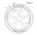
図1、2に示すように、サイドウォール部2のタイヤ最大幅位置Pwよりもタイヤ径方向内側には、タイヤ周方向に延びる環状の装飾帯10が形成されている。装飾帯10のタイヤ径方向幅は、例えば8mm以上とすることができる。また、装飾帯10の表面は平滑に形成されている。装飾帯10のタイヤ径方向内側には、凹凸からなるセリアル(刻印)15が形成され、また、装飾帯10のタイヤ径方向外側にも、凹凸からなるセリアル(刻印)16が形成されている。それぞれのセリアルは、タイヤサイズや標章等を示している。
装飾帯10は、タイヤ周方向に延び、タイヤ地色よりも明度が高い、複数(ここでは2本)の装飾ライン11、12を備える。この例では、タイヤ径方向外側の装飾ライン11は、白色(明度100%、彩度0%、色相0°)であり、タイヤ径方向内側の装飾ライン12は、緑色(明度60%、彩度66%、色相150°)である。
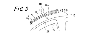
そして、図2に示すように、装飾ライン11および/または12の分断部に、文字、図形等の標章からなる標章部13を形成することができる。図2に示す実施形態では、標章部13のタイヤ径方向幅を、装飾帯10のタイヤ径方向幅とほぼ等しくしている。
装飾帯10は表面が平滑であり、これにより、リッジ等の凹凸による装飾を形成する場合に比して、タイヤの重量増加を十分に抑制することができる。なお、このような装飾帯10は、例えば印刷またはシールの接着によって形成することができる。
なお、図示はしないが、装飾ライン11および/または12を、タイヤ周方向に断続的に形成することもできる。また、装飾ラインを3本以上設けることもできる。
装飾帯10は、タイヤ周方向に延び、タイヤ地色よりも明度が高い、複数(ここでは2本)の装飾ライン11、12を備える。この例では、タイヤ径方向外側の装飾ライン11は、白色(明度100%、彩度0%、色相0°)であり、タイヤ径方向内側の装飾ライン12は、緑色(明度60%、彩度66%、色相150°)である。
そして、図2に示すように、装飾ライン11および/または12の分断部に、文字、図形等の標章からなる標章部13を形成することができる。図2に示す実施形態では、標章部13のタイヤ径方向幅を、装飾帯10のタイヤ径方向幅とほぼ等しくしている。
装飾帯10は表面が平滑であり、これにより、リッジ等の凹凸による装飾を形成する場合に比して、タイヤの重量増加を十分に抑制することができる。なお、このような装飾帯10は、例えば印刷またはシールの接着によって形成することができる。
なお、図示はしないが、装飾ライン11および/または12を、タイヤ周方向に断続的に形成することもできる。また、装飾ラインを3本以上設けることもできる。
ところで、図1はタイヤ半部の断面図であるが、他方のタイヤ半部には装飾帯10を形成せず、装飾帯10が車両の幅方向外側となるように、タイヤを車両に装着させることができる。また、他方のタイヤ半部が、図に示すところとは対称の構成を有するように構成することもできる。
上述したように、装飾ライン11、12の明度を、略黒色であるタイヤ地色の明度よりも高くすることで、装飾帯10の視認性を向上させることができ、遠くからでも装飾帯10を視認することができる。
また、装飾帯10は、明度80%以上の明度が最も高い装飾ライン11と、装飾ライン11とは明度および/または色相が互いに異なる(ここでは両方とも異なる)装飾ライン12とを備える。これにより、明度の高い装飾ライン11が、光を反射して明度が高い、リムフランジ21のように見えるため、リム径をより大きく見せることができる。
また、装飾ライン11とは明度が異なる装飾ライン12を備えることによって、一つの装飾ラインだと違和感があったものの、複数の装飾ラインとすることでホイール部分の凹凸感(タイヤ径方向の凹凸)を表現でき、違和感なくリムを大きく見せることができる。
また、装飾帯10は、明度80%以上の明度が最も高い装飾ライン11と、装飾ライン11とは明度および/または色相が互いに異なる(ここでは両方とも異なる)装飾ライン12とを備える。これにより、明度の高い装飾ライン11が、光を反射して明度が高い、リムフランジ21のように見えるため、リム径をより大きく見せることができる。
また、装飾ライン11とは明度が異なる装飾ライン12を備えることによって、一つの装飾ラインだと違和感があったものの、複数の装飾ラインとすることでホイール部分の凹凸感(タイヤ径方向の凹凸)を表現でき、違和感なくリムを大きく見せることができる。
そして、この実施形態のタイヤでは、タイヤ径方向最外側の装飾ライン11が最も明度が高くなっている。これにより、装飾ライン11を、ホイールのタイヤ径方向最外に位置し、光を反射して明度が高い、リムフランジ21のように見せることができる。また、装飾ライン11よりもタイヤ径方向内側に形成され、明度が装飾ライン11以下である装飾ライン12を、リムフランジのタイヤ径方向内側のディスク部外輪縁22のように見せることができる。これらの作用により、この実施形態のタイヤでは、リム径をより大きく見せることができる。
また、装飾ライン12を有彩色とすることで、ブランドイメージやタイヤの付加価値を強調することができる。例えばこの実施形態のように、装飾ライン12を緑色とすることで、看者に対して樹木の葉をイメージさせ、環境負荷の小さいタイヤであるイメージを与えることができる。
そして、図1及び図2に示すように、装飾帯10のタイヤ径方向最外端10aは、タイヤ最大幅位置Pwよりもタイヤ径方向内側に位置している。このように、負荷転動時等の歪みが小さい領域に装飾帯10を配置することで、装飾帯の剥離や亀裂を抑制し、装飾帯の耐久性を向上させることができる。
ここで、図1に示すように、装飾帯10のタイヤ径方向最外端10aと、ビードベースライン1aとのタイヤ径方向距離dを、タイヤ断面高さSHの35%以上50%未満とすることが、装飾帯10の剥離や亀裂を十分抑制しつつ、装飾帯10の視認性を高める観点から好ましく、また、タイヤサイズや標章等を示すセリアルを配置するスペースを確保する観点からも好ましい。
すなわち、dがSHの35%よりも小さい場合には、装飾帯の視認性が低下するおそれがあり、また、装飾帯のタイヤ径方向内側にセリアルを配置するスペースを十分に確保できないおそれがある。また、dがSHの50%以上の場合には、負荷転動時等の歪みが比較的大きい領域に装飾帯10が配置されて、装飾帯の剥離や亀裂を十分に抑制できないおそれがあり、また、装飾帯のタイヤ径方向外側にセリアルを配置するスペースを十分に確保できないおそれがある。
すなわち、dがSHの35%よりも小さい場合には、装飾帯の視認性が低下するおそれがあり、また、装飾帯のタイヤ径方向内側にセリアルを配置するスペースを十分に確保できないおそれがある。また、dがSHの50%以上の場合には、負荷転動時等の歪みが比較的大きい領域に装飾帯10が配置されて、装飾帯の剥離や亀裂を十分に抑制できないおそれがあり、また、装飾帯のタイヤ径方向外側にセリアルを配置するスペースを十分に確保できないおそれがある。
また、装飾帯10のそれぞれの装飾ライン11、12のタイヤ径方向幅w1、w2を、タイヤ断面高さSHの2~10%とすることが、タイヤの歪みに対する装飾帯の耐久性を確保しつつ、装飾帯の視認性を高める観点から好ましい。
すなわち、w1またはw2がSHの2%未満の場合には、装飾ラインが細くなりすぎて視認性が低下するおそれがある。また、w1またはw2がSHの10%よりも大きい場合には、装飾ラインの端部に歪みが集中して剥離が生じやすく、装飾ラインの耐久性が低下するおそれがある。
すなわち、w1またはw2がSHの2%未満の場合には、装飾ラインが細くなりすぎて視認性が低下するおそれがある。また、w1またはw2がSHの10%よりも大きい場合には、装飾ラインの端部に歪みが集中して剥離が生じやすく、装飾ラインの耐久性が低下するおそれがある。
そして、明度が最も高い装飾ライン11を明度100%の白色とすることが、装飾帯10の視認性を高め、リム径をより確実に大きく見せる観点から好ましい。
ここにおいて、装飾ライン11、12同士を、タイヤ径方向に離間して配置することが、それぞれの装飾ライン11、12の視認性を高める観点から好ましい。すなわち、装飾ライン11、12同士をタイヤ径方向に隣接して配置すると、装飾ライン11、12が一本のラインに見えやすくなり、所期する視覚的効果を発揮できなくなるおそれがある。
なお、装飾ライン11と12との間の隙間14のタイヤ径方向幅wgは、例えば1.5mmとすることができる。
なお、装飾ライン11と12との間の隙間14のタイヤ径方向幅wgは、例えば1.5mmとすることができる。
そしてまた、図1に示すカーカスプライ6の端部6eを、装飾帯10のタイヤ径方向最内端10bと、装飾帯10のタイヤ径方向最外端10aとの間以外のタイヤ径方向領域(図1に示す実施形態では、装飾帯10のタイヤ径方向最外端10aよりもタイヤ径方向外側)に配置することが、歪みが大きなカーカスプライの端部6eから装飾帯10を離隔させて、装飾帯10の耐久性を高める観点から好ましい。
ところで、明度が最も高い装飾ライン11は視認性が高く、また太く見える。そのため、明度が最も高い装飾ライン11のタイヤ径方向幅w1を、他の装飾ライン12のタイヤ径方向幅w2よりも狭くすることで、装飾ライン11と装飾ライン12とのバランスがとれて、看者の違和感を無くすことができるとともに、リム径をより確実に大きく見せることができる。
ここで、標章部13の明度を、明度が最も高い装飾ライン11の明度以上とすることが、装飾ライン11の効果を低下させずに標章部を配置する観点から好ましい。
また、図3に示すように、標章部13とタイヤ周方向に隣接する領域で、最も明度が低い装飾ライン12のタイヤ径方向幅を拡幅させて拡幅部12aを形成し、当該拡幅部12aで装飾ライン12を終端させることが、標章部13周囲の明度を標章部13よりも低くして、標章部13の視認性を高める観点から好ましい。
ところで、装飾帯10を印刷で形成する場合には、UVインクを用いることが好ましい。この場合には、UVインクに紫外線を照射することでインクが瞬間的に硬化するため、装飾帯の剥離を抑制することができるとともに、装飾帯を形成する際にインクがたれにくくなり、作業性を向上させることができる。
そして、この実施形態のタイヤでは、図1に示すように、カーカスプライ6のタイヤ外面側に、老化防止剤を含まない汚染防止ゴム層7が配設される。装飾帯10は、この汚染防止ゴム層7に隣接している。この構成をとることで、老化防止剤による装飾帯10の汚染を有効に抑制することができる。
なお、汚染防止ゴム層7のゴム成分としては、天然ゴム(NR)、ブチルゴム(IIR)、ハロゲン化ブチルゴム、イソプレンゴム(IR)、ブタジエンゴム(BR)、スチレンブタジエンゴム(SBR)、クロロプレンゴム(CR)、アクリロニトリルブタジエンゴム(NBR)、エチレンプロピレンジエン三元共重合体(EPDM)等を単独または2種以上の組合せで配合することができる。なお、汚染防止ゴム層にエチレンプロピレンジエン三元共重合体を配合した場合は、汚染防止ゴム層中に、エチレンプロピレンジエン三元共重合体が占める割合を、ゴム成分100重量部中80重量部以上とすることが好適である。
また、汚染防止ゴム層7の少なくとも一部に、ブチル系ゴムを含ませることで、汚染防止ゴム層での老化防止剤の透過を低減させて、他のゴム層に含まれる老化防止剤による装飾帯10の汚染をより有効に防止することができる。
前記汚染防止ゴム層7がさらに無機粘土鉱物を含む場合には、汚染防止ゴム層での老化防止剤の透過を一層低減させて、他のゴム層による装飾帯10の汚染防止効果をより一層高めることができる。
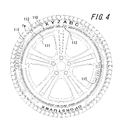
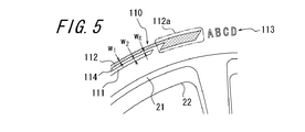
次に、本発明の他の実施形態のタイヤを図4および図5に示す。このタイヤには、サイドウォール部2のタイヤ最大幅位置Pwよりもタイヤ径方向内側に、タイヤ周方向に延びる環状の装飾帯110が形成されている。装飾帯110は、明度が80%以上であり明度が最も高い装飾ライン111をタイヤ径方向内側に、明度が最も低い装飾ライン112をタイヤ径方向外側に備える。装飾ライン111は白色(明度100%、彩度0%、色相0°)であり、装飾ライン112は青色(明度60%、彩度100%、色相219°)である。また、装飾帯110のタイヤ径方向内側および外側にはそれぞれ、図2及び図3に示す実施形態と同様の、セリアル115及び116が形成されている。そして図5に示すように、装飾ライン111と装飾ライン112との間には、タイヤ径方向幅wgの隙間114が形成されている。標章部113とタイヤ周方向に隣接する領域には、最も明度が低い装飾ライン112のタイヤ径方向幅を拡幅させて拡幅部112aが形成され、当該拡幅部112aで装飾ライン112が終端している。
この実施形態のタイヤでも、明度が高い装飾ライン111が、リムフランジ21のように見えるため、リム径をより大きく見せることができる。また、有彩色の装飾ライン112をタイヤ径方向外側に配置させることで、装飾ライン112の色味を強調し、ブランドイメージを訴求する効果等を高めることができる。
この発明に従う実施例タイヤ1~10と、比較例タイヤ1~4を試作した。タイヤのサイズは205/55R16であり、タイヤ断面高さSHが114mmである。タイヤのサイドウォール部には、タイヤ周方向に延び、タイヤ地色(明度10%、彩度0%、色相0°)よりも明度が高い、二本(比較例タイヤ2のみ一本)の装飾ラインを備える装飾帯が、タイヤ最大幅位置(ビードベースラインとのタイヤ径方向距離が52.5mm、タイヤ断面高さSHの0.46倍)よりもタイヤ径方向内側に形成されている。また、比較例タイヤ2以外の試作タイヤでは、装飾ライン同士はタイヤ径方向に1.5mm離間している。
それぞれの試作タイヤの、タイヤ径方向外側の装飾ラインの明度、タイヤ径方向内側の装飾ラインの明度、装飾帯のタイヤ径方向外端とビードベースラインとのタイヤ径方向距離dとタイヤ断面高さSHとの比、装飾帯のそれぞれの装飾ラインのタイヤ径方向幅w1、w2とタイヤ断面高さSHとの比、カーカスプライの端部が装飾帯のタイヤ径方向最内端と最外端との間のタイヤ径方向領域に配置されているか否か(以下、「プライ端部と装飾帯との重複」といい、○または×で示す)を、表1に示す。
それぞれの試作タイヤの、タイヤ径方向外側の装飾ラインの明度、タイヤ径方向内側の装飾ラインの明度、装飾帯のタイヤ径方向外端とビードベースラインとのタイヤ径方向距離dとタイヤ断面高さSHとの比、装飾帯のそれぞれの装飾ラインのタイヤ径方向幅w1、w2とタイヤ断面高さSHとの比、カーカスプライの端部が装飾帯のタイヤ径方向最内端と最外端との間のタイヤ径方向領域に配置されているか否か(以下、「プライ端部と装飾帯との重複」といい、○または×で示す)を、表1に示す。
<装飾ラインの視認性>
それぞれの試作タイヤを適用リムに組み付けて、装飾帯の視認性について調査した。具体的には、試作したタイヤのそれぞれを、20人の看者が観察して、装飾帯の視認性が向上し通常のタイヤよりもリム径が大きく感じるかのアンケート調査を行った。その結果を表1に示す。リム径が大きく感じたと回答した看者の数が18人以上の場合をA、10~17人の場合をB、9人以下の場合をCとする。なお表1には、リム径が大きく感じたと回答した看者の人数も併記した。
それぞれの試作タイヤを適用リムに組み付けて、装飾帯の視認性について調査した。具体的には、試作したタイヤのそれぞれを、20人の看者が観察して、装飾帯の視認性が向上し通常のタイヤよりもリム径が大きく感じるかのアンケート調査を行った。その結果を表1に示す。リム径が大きく感じたと回答した看者の数が18人以上の場合をA、10~17人の場合をB、9人以下の場合をCとする。なお表1には、リム径が大きく感じたと回答した看者の人数も併記した。
<装飾帯の耐久性>
それぞれの試作タイヤを適用リムに組み付けて、規定内圧を充填し、ドラム試験器を用いて、最大負荷荷重を負荷し、一定速度で試作タイヤを1万km、3万km走行させ、走行後に装飾帯に剥離が発生しているかを確認した。剥離が発生しなかった場合を○、剥離が発生した場合を×とする。
それぞれの試作タイヤを適用リムに組み付けて、規定内圧を充填し、ドラム試験器を用いて、最大負荷荷重を負荷し、一定速度で試作タイヤを1万km、3万km走行させ、走行後に装飾帯に剥離が発生しているかを確認した。剥離が発生しなかった場合を○、剥離が発生した場合を×とする。

試験結果から、装飾帯のタイヤ径方向最外端がタイヤ最大幅位置よりもタイヤ径方向内側に位置し、装飾帯はタイヤ周方向に延びタイヤ地色よりも明度が高い複数の装飾ラインを備え、装飾ラインのうち明度が最も高い装飾ラインは、明度が80%以上であるとともに、他の少なくとも一本の装飾ラインと、明度または色相が異なる実施例タイヤでは、比較例タイヤよりも装飾帯の視認性が向上していることが明らかになった。
1:ビード部、 2:サイドウォール部、 3:トレッド部、 4:ビードコア、
6:カーカスプライ、 6e:カーカスプライの端部、 10:装飾帯、
10a:装飾帯のタイヤ径方向最外端、 10b:装飾帯のタイヤ径方向最内端、
11、12、111、112:装飾ライン、 13、113:標章部、
14、114:隙間、 15、16、115、116:セリアル(刻印)、
21:リムフランジ、 22:ディスク部外輪縁
6:カーカスプライ、 6e:カーカスプライの端部、 10:装飾帯、
10a:装飾帯のタイヤ径方向最外端、 10b:装飾帯のタイヤ径方向最内端、
11、12、111、112:装飾ライン、 13、113:標章部、
14、114:隙間、 15、16、115、116:セリアル(刻印)、
21:リムフランジ、 22:ディスク部外輪縁
Claims (8)
- ビードコアを埋設した一対のビード部、ビード部からタイヤ径方向外側に延びる一対のサイドウォール部、および両サイドウォール部間にまたがって延びるトレッド部とを具え、前記サイドウォール部に表面が平滑な装飾帯が形成されてなる空気入りタイヤであって、
前記装飾帯のタイヤ径方向最外端が、タイヤ最大幅位置よりもタイヤ径方向内側に位置し、
前記装飾帯は、タイヤ周方向に延び、タイヤ地色よりも明度が高い、複数の装飾ラインを備え、
前記装飾ラインのうち明度が最も高い装飾ラインは、明度が80%以上であるとともに、他の少なくとも1本の装飾ラインと、明度および/または色相が異なることを特徴とする、空気入りタイヤ。 - タイヤ径方向最外側の装飾ラインを明度が最も高い装飾ラインとしてなる、請求項1に記載の空気入りタイヤ。
- 前記装飾帯のタイヤ径方向最外端と、ビードベースラインとのタイヤ径方向距離を、タイヤ断面高さSHの35%以上50%未満としてなる、請求項1または2に記載の空気入りタイヤ。
- 前記装飾帯のそれぞれの装飾ラインのタイヤ径方向幅を、タイヤ断面高さSHの2~10%としてなる、請求項1~3のいずれか一項に記載の空気入りタイヤ。
- 前記明度が最も高い装飾ラインを明度100%の白色としてなる、請求項1~4のいずれか一項に記載の空気入りタイヤ。
- 前記装飾ライン同士を、タイヤ径方向に離間して配置してなる、請求項1~5のいずれか一項に記載の空気入りタイヤ。
- カーカスプライの端部を、前記装飾帯のタイヤ径方向最内端と、前記装飾帯のタイヤ径方向最外端との間以外のタイヤ径方向領域に配置してなる、請求項1~6のいずれか一項に記載の空気入りタイヤ。
- 前記明度が最も高い装飾ラインのタイヤ径方向幅を、他の装飾ラインのタイヤ径方向幅よりも狭くしてなる、請求項1~7のいずれか一項に記載の空気入りタイヤ。
Priority Applications (3)
| Application Number | Priority Date | Filing Date | Title |
|---|---|---|---|
| EP13871098.3A EP2944480B1 (en) | 2013-01-09 | 2013-12-16 | Pneumatic tire |
| CN201380069853.4A CN104918797B (zh) | 2013-01-09 | 2013-12-16 | 充气轮胎 |
| US14/652,620 US9931894B2 (en) | 2013-01-09 | 2013-12-16 | Pneumatic tire |
Applications Claiming Priority (2)
| Application Number | Priority Date | Filing Date | Title |
|---|---|---|---|
| JP2013-001836 | 2013-01-09 | ||
| JP2013001836A JP5519812B1 (ja) | 2013-01-09 | 2013-01-09 | 空気入りタイヤ |
Publications (1)
| Publication Number | Publication Date |
|---|---|
| WO2014108961A1 true WO2014108961A1 (ja) | 2014-07-17 |
Family
ID=51031304
Family Applications (1)
| Application Number | Title | Priority Date | Filing Date |
|---|---|---|---|
| PCT/JP2013/007376 Ceased WO2014108961A1 (ja) | 2013-01-09 | 2013-12-16 | 空気入りタイヤ |
Country Status (5)
| Country | Link |
|---|---|
| US (1) | US9931894B2 (ja) |
| EP (1) | EP2944480B1 (ja) |
| JP (1) | JP5519812B1 (ja) |
| CN (1) | CN104918797B (ja) |
| WO (1) | WO2014108961A1 (ja) |
Families Citing this family (6)
| Publication number | Priority date | Publication date | Assignee | Title |
|---|---|---|---|---|
| JP6281598B2 (ja) * | 2016-05-26 | 2018-02-21 | 横浜ゴム株式会社 | 空気入りタイヤ |
| KR101840289B1 (ko) * | 2017-08-28 | 2018-03-20 | 오행준 | 식별용이형 자전거 바퀴 및 자전거 차체 |
| JP7087248B2 (ja) * | 2017-12-11 | 2022-06-21 | 株式会社ブリヂストン | タイヤ |
| JP2019104386A (ja) * | 2017-12-12 | 2019-06-27 | 株式会社ブリヂストン | 装飾体 |
| JP7043855B2 (ja) * | 2018-01-30 | 2022-03-30 | 横浜ゴム株式会社 | 空気入りタイヤ |
| JP7151226B2 (ja) * | 2018-07-10 | 2022-10-12 | 住友ゴム工業株式会社 | タイヤ |
Citations (4)
| Publication number | Priority date | Publication date | Assignee | Title |
|---|---|---|---|---|
| JP2000255223A (ja) * | 1999-03-05 | 2000-09-19 | Bridgestone Corp | タイヤ |
| WO2012004947A1 (ja) * | 2010-07-08 | 2012-01-12 | 株式会社ブリヂストン | タイヤ |
| JP2012061922A (ja) * | 2010-09-15 | 2012-03-29 | Bridgestone Corp | タイヤ |
| JP2012076555A (ja) | 2010-09-30 | 2012-04-19 | Bridgestone Corp | タイヤ |
Family Cites Families (13)
| Publication number | Priority date | Publication date | Assignee | Title |
|---|---|---|---|---|
| US3253634A (en) * | 1964-02-19 | 1966-05-31 | Goodyear Tire & Rubber | Pneumatic tire |
| US4413663A (en) * | 1981-11-27 | 1983-11-08 | Sullenger Gordon A | Pneumatic tire |
| AT391835B (de) | 1988-09-07 | 1990-12-10 | Semperit Ag | Gummiartikel, insbesondere fahrzeugreifen |
| DE4422548C2 (de) * | 1994-06-28 | 1997-08-07 | Uniroyal Englebert Gmbh | Aufbringen eines Zeichens in eine sichtbare Fläche eines Reifens |
| EP1109681B1 (en) * | 1998-09-02 | 2003-03-19 | The Goodyear Tire & Rubber Company | A tire sidewall |
| US6536368B2 (en) * | 2000-05-02 | 2003-03-25 | William S. Hendrie | Tire |
| DE10250787A1 (de) * | 2002-10-30 | 2004-05-19 | Vitodesign Gmbh & Co.Kg | Reifen und Verfahren zu dessen Herstellung |
| US20050224153A1 (en) * | 2004-04-12 | 2005-10-13 | Al Speyer | Use of colored indicia on tires as a designator |
| DE102004032801A1 (de) * | 2004-07-07 | 2006-02-16 | Adam Opel Ag | Kraftfahrzeugreifen |
| JP4925803B2 (ja) * | 2006-12-04 | 2012-05-09 | 株式会社ブリヂストン | タイヤ |
| JP4666109B1 (ja) | 2010-05-07 | 2011-04-06 | 横浜ゴム株式会社 | 空気入りタイヤ |
| JP4911332B2 (ja) * | 2010-09-08 | 2012-04-04 | 横浜ゴム株式会社 | 空気入りタイヤ及びその加硫用金型 |
| JP5683908B2 (ja) | 2010-11-08 | 2015-03-11 | 株式会社ブリヂストン | タイヤ表面印刷方法およびタイヤ |
-
2013
- 2013-01-09 JP JP2013001836A patent/JP5519812B1/ja not_active Expired - Fee Related
- 2013-12-16 WO PCT/JP2013/007376 patent/WO2014108961A1/ja not_active Ceased
- 2013-12-16 CN CN201380069853.4A patent/CN104918797B/zh not_active Expired - Fee Related
- 2013-12-16 US US14/652,620 patent/US9931894B2/en not_active Expired - Fee Related
- 2013-12-16 EP EP13871098.3A patent/EP2944480B1/en not_active Not-in-force
Patent Citations (4)
| Publication number | Priority date | Publication date | Assignee | Title |
|---|---|---|---|---|
| JP2000255223A (ja) * | 1999-03-05 | 2000-09-19 | Bridgestone Corp | タイヤ |
| WO2012004947A1 (ja) * | 2010-07-08 | 2012-01-12 | 株式会社ブリヂストン | タイヤ |
| JP2012061922A (ja) * | 2010-09-15 | 2012-03-29 | Bridgestone Corp | タイヤ |
| JP2012076555A (ja) | 2010-09-30 | 2012-04-19 | Bridgestone Corp | タイヤ |
Non-Patent Citations (1)
| Title |
|---|
| See also references of EP2944480A4 * |
Also Published As
| Publication number | Publication date |
|---|---|
| EP2944480B1 (en) | 2018-11-07 |
| EP2944480A1 (en) | 2015-11-18 |
| JP2014133453A (ja) | 2014-07-24 |
| CN104918797A (zh) | 2015-09-16 |
| US9931894B2 (en) | 2018-04-03 |
| JP5519812B1 (ja) | 2014-06-11 |
| CN104918797B (zh) | 2017-08-04 |
| US20150336432A1 (en) | 2015-11-26 |
| EP2944480A4 (en) | 2016-11-09 |
Similar Documents
| Publication | Publication Date | Title |
|---|---|---|
| JP5519812B1 (ja) | 空気入りタイヤ | |
| CN103097151B (zh) | 轮胎 | |
| CN104507709B (zh) | 具有层合物的轮胎 | |
| WO2014073157A1 (ja) | タイヤ | |
| JP5869848B2 (ja) | タイヤ | |
| JP5603958B2 (ja) | 空気入りタイヤ | |
| US20140311646A1 (en) | Tire | |
| WO2012042812A1 (ja) | タイヤ | |
| CN103857541B (zh) | 充气轮胎 | |
| JP2009137457A (ja) | 空気入りタイヤ及びその製造方法 | |
| US10493805B2 (en) | Pneumatic tire | |
| WO2013099103A1 (ja) | ゴム装飾物及びタイヤ | |
| JP5865442B2 (ja) | 空気入りタイヤ | |
| JP5566363B2 (ja) | 空気入りタイヤ | |
| WO2017145982A1 (ja) | 空気入りタイヤ | |
| JP5241248B2 (ja) | 空気入りタイヤ | |
| WO2016021139A1 (ja) | 空気入りタイヤ | |
| JP5566362B2 (ja) | タイヤ | |
| JP5902486B2 (ja) | タイヤ | |
| JP2009035182A (ja) | 空気入りタイヤ | |
| WO2016021140A1 (ja) | 空気入りタイヤ | |
| JP2014221632A (ja) | 空気入りタイヤ | |
| JP2018047769A (ja) | 空気入りタイヤ | |
| JP2009107537A (ja) | 空気入りタイヤ |
Legal Events
| Date | Code | Title | Description |
|---|---|---|---|
| 121 | Ep: the epo has been informed by wipo that ep was designated in this application |
Ref document number: 13871098 Country of ref document: EP Kind code of ref document: A1 |
|
| WWE | Wipo information: entry into national phase |
Ref document number: 14652620 Country of ref document: US |
|
| NENP | Non-entry into the national phase |
Ref country code: DE |
|
| WWE | Wipo information: entry into national phase |
Ref document number: 2013871098 Country of ref document: EP |