WO2014109180A1 - 熱間製管用プラグ - Google Patents
熱間製管用プラグ Download PDFInfo
- Publication number
- WO2014109180A1 WO2014109180A1 PCT/JP2013/083635 JP2013083635W WO2014109180A1 WO 2014109180 A1 WO2014109180 A1 WO 2014109180A1 JP 2013083635 W JP2013083635 W JP 2013083635W WO 2014109180 A1 WO2014109180 A1 WO 2014109180A1
- Authority
- WO
- WIPO (PCT)
- Prior art keywords
- plug
- layer
- build
- plug body
- thermal spray
- Prior art date
- Legal status (The legal status is an assumption and is not a legal conclusion. Google has not performed a legal analysis and makes no representation as to the accuracy of the status listed.)
- Ceased
Links
Images



Classifications
-
- B—PERFORMING OPERATIONS; TRANSPORTING
- B21—MECHANICAL METAL-WORKING WITHOUT ESSENTIALLY REMOVING MATERIAL; PUNCHING METAL
- B21B—ROLLING OF METAL
- B21B25/00—Mandrels for metal tube rolling mills, e.g. mandrels of the types used in the methods covered by group B21B17/00; Accessories or auxiliary means therefor ; Construction of, or alloys for, mandrels or plugs
-
- B—PERFORMING OPERATIONS; TRANSPORTING
- B21—MECHANICAL METAL-WORKING WITHOUT ESSENTIALLY REMOVING MATERIAL; PUNCHING METAL
- B21B—ROLLING OF METAL
- B21B17/00—Tube-rolling by rollers of which the axes are arranged essentially perpendicular to the axis of the work, e.g. "axial" tube-rolling
- B21B17/02—Tube-rolling by rollers of which the axes are arranged essentially perpendicular to the axis of the work, e.g. "axial" tube-rolling with mandrel, i.e. the mandrel rod contacts the rolled tube over the rod length
-
- B—PERFORMING OPERATIONS; TRANSPORTING
- B21—MECHANICAL METAL-WORKING WITHOUT ESSENTIALLY REMOVING MATERIAL; PUNCHING METAL
- B21B—ROLLING OF METAL
- B21B19/00—Tube-rolling by rollers arranged outside the work and having their axes not perpendicular to the axis of the work
- B21B19/02—Tube-rolling by rollers arranged outside the work and having their axes not perpendicular to the axis of the work the axes of the rollers being arranged essentially diagonally to the axis of the work, e.g. "cross" tube-rolling ; Diescher mills, Stiefel disc piercers or Stiefel rotary piercers
- B21B19/04—Rolling basic material of solid, i.e. non-hollow, structure; Piercing, e.g. rotary piercing mills
-
- B—PERFORMING OPERATIONS; TRANSPORTING
- B23—MACHINE TOOLS; METAL-WORKING NOT OTHERWISE PROVIDED FOR
- B23K—SOLDERING OR UNSOLDERING; WELDING; CLADDING OR PLATING BY SOLDERING OR WELDING; CUTTING BY APPLYING HEAT LOCALLY, e.g. FLAME CUTTING; WORKING BY LASER BEAM
- B23K10/00—Welding or cutting by means of a plasma
- B23K10/02—Plasma welding
- B23K10/027—Welding for purposes other than joining, e.g. build-up welding
-
- B—PERFORMING OPERATIONS; TRANSPORTING
- B23—MACHINE TOOLS; METAL-WORKING NOT OTHERWISE PROVIDED FOR
- B23K—SOLDERING OR UNSOLDERING; WELDING; CLADDING OR PLATING BY SOLDERING OR WELDING; CUTTING BY APPLYING HEAT LOCALLY, e.g. FLAME CUTTING; WORKING BY LASER BEAM
- B23K9/00—Arc welding or cutting
- B23K9/04—Welding for other purposes than joining, e.g. built-up welding
- B23K9/044—Built-up welding on three-dimensional surfaces
- B23K9/046—Built-up welding on three-dimensional surfaces on surfaces of revolution
-
- C—CHEMISTRY; METALLURGY
- C23—COATING METALLIC MATERIAL; COATING MATERIAL WITH METALLIC MATERIAL; CHEMICAL SURFACE TREATMENT; DIFFUSION TREATMENT OF METALLIC MATERIAL; COATING BY VACUUM EVAPORATION, BY SPUTTERING, BY ION IMPLANTATION OR BY CHEMICAL VAPOUR DEPOSITION, IN GENERAL; INHIBITING CORROSION OF METALLIC MATERIAL OR INCRUSTATION IN GENERAL
- C23C—COATING METALLIC MATERIAL; COATING MATERIAL WITH METALLIC MATERIAL; SURFACE TREATMENT OF METALLIC MATERIAL BY DIFFUSION INTO THE SURFACE, BY CHEMICAL CONVERSION OR SUBSTITUTION; COATING BY VACUUM EVAPORATION, BY SPUTTERING, BY ION IMPLANTATION OR BY CHEMICAL VAPOUR DEPOSITION, IN GENERAL
- C23C4/00—Coating by spraying the coating material in the molten state, e.g. by flame, plasma or electric discharge
- C23C4/02—Pretreatment of the material to be coated, e.g. for coating on selected surface areas
-
- C—CHEMISTRY; METALLURGY
- C23—COATING METALLIC MATERIAL; COATING MATERIAL WITH METALLIC MATERIAL; CHEMICAL SURFACE TREATMENT; DIFFUSION TREATMENT OF METALLIC MATERIAL; COATING BY VACUUM EVAPORATION, BY SPUTTERING, BY ION IMPLANTATION OR BY CHEMICAL VAPOUR DEPOSITION, IN GENERAL; INHIBITING CORROSION OF METALLIC MATERIAL OR INCRUSTATION IN GENERAL
- C23C—COATING METALLIC MATERIAL; COATING MATERIAL WITH METALLIC MATERIAL; SURFACE TREATMENT OF METALLIC MATERIAL BY DIFFUSION INTO THE SURFACE, BY CHEMICAL CONVERSION OR SUBSTITUTION; COATING BY VACUUM EVAPORATION, BY SPUTTERING, BY ION IMPLANTATION OR BY CHEMICAL VAPOUR DEPOSITION, IN GENERAL
- C23C4/00—Coating by spraying the coating material in the molten state, e.g. by flame, plasma or electric discharge
- C23C4/04—Coating by spraying the coating material in the molten state, e.g. by flame, plasma or electric discharge characterised by the coating material
- C23C4/06—Metallic material
-
- C—CHEMISTRY; METALLURGY
- C23—COATING METALLIC MATERIAL; COATING MATERIAL WITH METALLIC MATERIAL; CHEMICAL SURFACE TREATMENT; DIFFUSION TREATMENT OF METALLIC MATERIAL; COATING BY VACUUM EVAPORATION, BY SPUTTERING, BY ION IMPLANTATION OR BY CHEMICAL VAPOUR DEPOSITION, IN GENERAL; INHIBITING CORROSION OF METALLIC MATERIAL OR INCRUSTATION IN GENERAL
- C23C—COATING METALLIC MATERIAL; COATING MATERIAL WITH METALLIC MATERIAL; SURFACE TREATMENT OF METALLIC MATERIAL BY DIFFUSION INTO THE SURFACE, BY CHEMICAL CONVERSION OR SUBSTITUTION; COATING BY VACUUM EVAPORATION, BY SPUTTERING, BY ION IMPLANTATION OR BY CHEMICAL VAPOUR DEPOSITION, IN GENERAL
- C23C4/00—Coating by spraying the coating material in the molten state, e.g. by flame, plasma or electric discharge
- C23C4/12—Coating by spraying the coating material in the molten state, e.g. by flame, plasma or electric discharge characterised by the method of spraying
- C23C4/131—Wire arc spraying
-
- B—PERFORMING OPERATIONS; TRANSPORTING
- B23—MACHINE TOOLS; METAL-WORKING NOT OTHERWISE PROVIDED FOR
- B23K—SOLDERING OR UNSOLDERING; WELDING; CLADDING OR PLATING BY SOLDERING OR WELDING; CUTTING BY APPLYING HEAT LOCALLY, e.g. FLAME CUTTING; WORKING BY LASER BEAM
- B23K2101/00—Articles made by soldering, welding or cutting
- B23K2101/20—Tools
-
- B—PERFORMING OPERATIONS; TRANSPORTING
- B23—MACHINE TOOLS; METAL-WORKING NOT OTHERWISE PROVIDED FOR
- B23K—SOLDERING OR UNSOLDERING; WELDING; CLADDING OR PLATING BY SOLDERING OR WELDING; CUTTING BY APPLYING HEAT LOCALLY, e.g. FLAME CUTTING; WORKING BY LASER BEAM
- B23K2103/00—Materials to be soldered, welded or cut
- B23K2103/02—Iron or ferrous alloys
- B23K2103/04—Steel or steel alloys
-
- B—PERFORMING OPERATIONS; TRANSPORTING
- B23—MACHINE TOOLS; METAL-WORKING NOT OTHERWISE PROVIDED FOR
- B23K—SOLDERING OR UNSOLDERING; WELDING; CLADDING OR PLATING BY SOLDERING OR WELDING; CUTTING BY APPLYING HEAT LOCALLY, e.g. FLAME CUTTING; WORKING BY LASER BEAM
- B23K2103/00—Materials to be soldered, welded or cut
- B23K2103/02—Iron or ferrous alloys
- B23K2103/04—Steel or steel alloys
- B23K2103/05—Stainless steel
Definitions
- the present invention relates to a plug, and more particularly to a plug for hot pipe making used in a drilling machine (piercer) and an elongator.
- the hot pipe making plug is simply referred to as “plug”.
- the Mannesmann pipe manufacturing method is widely adopted as a seamless pipe manufacturing method.
- a round billet heated to around 1200 ° C. is pierced and rolled with a piercing machine (piercer).
- the perforator includes a pair of inclined rolls and a plug.
- the plug is disposed on a pass line between the pair of inclined rolls.
- the punch the round billet is pushed into the plug while being rotated in the circumferential direction by the inclined roll.
- the round billet is pierced and rolled to form a hollow shell (hollow shell).
- the hollow shell is drawn and rolled, and the hollow shell is expanded and thinned.
- the elongator has the same configuration as the drilling machine, and includes a pair of inclined rolls and a plug.
- the plug is used for piercing and rolling a high-temperature round billet, stretching and rolling a hollow shell, and the like. Therefore, the plug receives high heat and high surface pressure from the round billet or the hollow shell. As a result, wear or seizure occurs on the plug surface, or melting damage occurs on the plug. The plug life is shortened due to wear and seizure of the plug surface and melting of the plug.
- an oxide scale film is formed on the surface of a plug body (plug base material).
- the oxide scale film blocks the heat from the round billet and suppresses the occurrence of seizure and melting damage.
- Patent Documents 1 to 5 below disclose plugs having an oxide scale film.
- the abrasion resistance of the oxide scale film is not high. Therefore, the oxide scale film is worn every time the round billet is pierced and rolled.
- the temperature of the plug body increases. As a result, the plug is seized or melted.
- the oxide scale film is remarkably worn.
- the oxide scale film When the oxide scale film is worn, the oxide scale film may be formed again on the plug body by heat treatment. However, since the heat treatment time is as long as several hours to several tens of hours, the production efficiency is lowered.
- Patent Documents 6 to 9 disclose plugs having other films instead of oxide scale films.
- the plug disclosed in Patent Document 6 includes an arc sprayed coating made of iron oxide. Arc sprayed coatings have better wear resistance than oxide scale coatings.
- the plugs disclosed in Patent Documents 7 to 9 have a built-up layer on the surface.
- the overlay layer is excellent in high temperature strength and wear resistance.
- the high temperature strength of the arc sprayed coating is lower than that of the overlay layer. Therefore, when the plug of Patent Document 6 is used for piercing and rolling of a high alloy billet, the plug is likely to be seized or melted, and the life of the plug may be shortened.
- Patent Documents 7 to 9 Since the plugs of Patent Documents 7 to 9 have a built-up layer, they are excellent in high temperature strength. However, even when the plugs of these documents are used for drilling or rolling high alloy billets, the plugs may be seized or melted and the plug life may be shortened.
- This invention is made
- a plug for hot pipe making according to an aspect of the present invention includes: a plug body; a build-up layer formed on a surface of the plug body around the axis of the plug body; and a surface of the build-up layer A thermal spray coating formed thereon.
- the build-up layer may be formed on the front surface of the plug body.
- the build-up layer may include a tapered surface.
- the thermal spray coating may be formed on the tapered surface.
- the sprayed coating may cover the entire surface of the build-up layer.
- the surface of the plug main body is a first surface region where the build-up layer is formed; the rear of the plug main body from the first surface region; And a second surface region of.
- the thermal spray coating may include a first thermal spray region formed on the surface of the build-up layer; and a second thermal spray region formed on the second surface region.
- the second sprayed region may be adjacent to the first sprayed region.
- the build-up layer may cover a tip of the plug body.
- the plug for hot pipe making which can improve a plug lifetime can be provided.
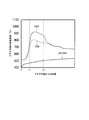
- FIG. 1 It is a figure which shows distribution of the surface temperature of the plug main body at the time of piercing-rolling calculated
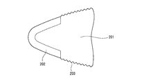
- FIG.6 and FIG.7 It is a longitudinal cross-sectional view of the other plug of this embodiment of a different structure from FIG.6 and FIG.7. It is a longitudinal cross-sectional view of the other plug of this embodiment of a different structure from FIG.6, FIG.7 and FIG.8. It is a longitudinal cross-sectional view of the plug used in the Example. It is a longitudinal cross-sectional view of the other plug used in the Example different from FIG.
- the inventor conducted investigations and examinations in order to improve the life of the plug, and obtained the following knowledge.
- the high temperature strength of the overlay layer is higher than that of the sprayed coating and the oxide scale coating.
- the heat shielding property of the overlay layer is lower than that of the thermal spray coating or the oxide scale coating.
- FIG. 1 is a diagram illustrating a result of simulating plug temperature during elongation rolling of a material (workpiece) by an elongator.
- FIG. 1 was obtained by the following method.
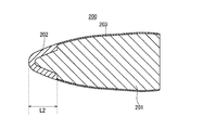
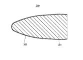
- the plugs 200 and 300 shown in FIGS. 2 and 3 were assumed.
- the plug 200 in FIG. 2 includes a plug main body 201, a build-up layer 202, and a sprayed coating 203.
- the build-up layer 202 was formed on the surface of the tip portion of the plug body 201 and covered the tip of the plug body 201.
- the length from the front end of the plug 200 to the rear end of the built-up layer 202 was L2.
- the sprayed coating 203 was formed in a region between the rear end of the built-up layer 202 and the rear end of the plug main body 201 (excluding the rear end surface of the plug main body 201) in the surface of the plug main body 201.
- the plug 300 in FIG. 3 includes a plug body 301 and an oxide scale film 302.
- the oxide scale film 302 was formed on the entire surface of the plug body 301 except for the rear end face.
- the plug 200 and the plug 300 were almost the same shape.
- a hollow shell was assumed as a material.
- the material of the hollow shell was set to SUS304, and the temperature condition was set to 1200 ° C.
- the rolling reduction by piercing and rolling was set to 25%, and the drawing and rolling time was set to 15 seconds.
- the simulation result shown in FIG. 1 was obtained.
- the horizontal axis in FIG. 1 indicates the distance from the tip of the plug 200 or 300.
- a one-dot chain line in the lower part of FIG. 1 schematically shows plug shapes of the plugs 200 and 300.
- the vertical axis in FIG. 1 indicates the surface temperature of the plug body 201 or 301.
- the inner surface of the material was in contact with the plugs 200 and 300 at the distance L1 (see FIG. 1). Therefore, the area
- a solid line C200 in FIG. 1 indicates the surface temperature of the plug body 201.
- a broken line C300 in FIG. 1 indicates the surface temperature of the plug body 301.
- the surface of the plug body 201 on which the build-up layer 202 is formed (distance L1 ⁇ The temperature (C200) in the region L2) was about 100 ° C. higher than the surface temperature (C300) of the corresponding plug body 301. Further, in the surface of the plug body 201, the temperature of the region where the thermal spray coating 203 behind the build-up layer 202 was formed was about 100 ° C. lower than the temperature of the region where the build-up layer 202 was formed.
- the heat shielding property of the overlay layer 202 is lower than that of the thermal spray coating 203 and the oxide scale coating 302. Therefore, in the region of the plug 200 where the build-up layer 202 is formed, the amount of heat input from the material (round billet or hollow shell) during piercing and rolling is increased.
- the build-up layer 202 has excellent high-temperature strength. Therefore, in the portion of the plug 200 where the build-up layer 202 is formed. The occurrence of wear and deformation is suppressed.
- the heat shielding property of the overlay layer 202 is lower than that of the oxide scale coating 302 and the thermal spray coating 203. Therefore, as shown in FIG. 1, the amount of heat that enters the plug body 201 from the material through the build-up layer 202 during piercing and rolling is from the amount of heat that enters the plug body 301 through the oxide scale film 302 and the thermal spray coating 203. The amount of heat entering the plug body 201 is larger. As a result, particularly when the plug 200 is used for piercing and rolling of a high alloy material containing a large amount of Ni and Cr, the temperature of the plug body 201 rises excessively and the plug 200 is deformed as shown in FIG. There is a case.
- the build-up layer 202 has excellent high-temperature strength. Therefore, the portion where the overlaying layer 202 is formed is not easily deformed. However, the portion of the plug body 201 where the overlay layer 202 is not formed (in other words, the portion where the sprayed coating 203 is formed) is easily deformed, and the surface becomes wavy. This is because the strength of the plug body 201 is increased due to the temperature rise.
- Such deformation of the plug main body 201 not only causes flaws on the inner surface of the hollow shell, but also tends to cause seizure or melting of the plug main body 201. This makes it difficult to use the plug 200 continuously. As a result, even the plug 200 having the build-up layer 202 may shorten the plug life.
- the inventor considered that if a thermal spray coating is formed on the surface of the build-up layer, heat from the material can be prevented from entering the plug body through the build-up layer.
- the thermal barrier property of the thermal spray coating is higher than that of the overlay layer. If a thermal spray coating is formed on the overlay layer, high thermal strength can be obtained by the overlay layer, and furthermore, high thermal barrier properties can be obtained by the thermal spray coating. Therefore, even when a plug is used for drilling and rolling of a high alloy material, the amount of heat entering the plug body having the build-up layer can be suppressed, and the plug life is improved.
- the plug of this embodiment is a plug for hot pipe making.
- the plug includes a plug body, a built-up layer, and a thermal spray coating.
- the build-up layer is formed on the surface of the plug body around the axis of the plug body.
- the thermal spray coating is formed on the surface of the overlay layer.
- the built-up layer has a high high-temperature strength, and thus suppresses deformation of the plug. Furthermore, since the thermal spray coating is formed on the build-up layer, heat input to the build-up layer is suppressed, and the temperature rise of the plug body during piercing and rolling can be suppressed. Therefore, deformation of the plug is suppressed, and melting damage and seizure hardly occur. Therefore, even when a high alloy material is rolled, the plug life can be increased.
- the overlay layer is preferably formed on the front surface of the plug body.
- the build-up layer includes a tapered surface that is inclined with respect to the central axis of the plug body.
- the thermal spray coating is formed on the tapered surface of the overlay layer.
- the sprayed coating on the overlay layer receives an external force in the direction of the overlay layer (force to press the spray coating against the overlay layer) during piercing and rolling. Therefore, the thermal spray coating is difficult to peel off from the overlay layer.
- the thermal spray coating covers the entire surface of the overlay layer.
- the surface of the plug body preferably includes a first surface region and a second surface region.
- a built-up layer is formed in the first surface region.
- the second surface region is adjacent to the rear end of the first surface region, and is disposed behind the plug body from the first surface region.
- the thermal spray coating includes first and second thermal spray areas. The first sprayed region is formed on the surface of the overlay layer. The second sprayed region is formed on the second surface region.
- a sprayed coating is also formed in the plug body at the rear portion of the built-up layer. Therefore, the heat insulating property of the plug is increased and the plug life is increased.
- the second sprayed region is adjacent to the first sprayed region.
- the plug according to the present embodiment is used for a punch or an elongator.
- the plug will be described using a punching machine as an example. However, the same applies to plugs used in an elongator.
- FIG. 5 is an overall configuration diagram of the punch 1. As shown in FIG. 5, the punching machine 1 includes a pair of inclined rolls 2, a plug 100, and a cored bar 3.
- the pair of inclined rolls 2 are arranged around the pass line PL.
- the inclined roll 2 is rolled while rotating the round billet BL, which is a material, in the circumferential direction.
- the inclined roll 2 may be a cone type or a barrel type.
- the plug 100 is disposed on a pass line PL between the pair of inclined rolls 2.
- the cored bar 3 has a rod shape and is disposed on the pass line PL.
- a plug 100 is attached to the tip of the core metal 3.
- the cored bar 3 fixes the plug 100 on the pass line PL.
- the plug 100 is pushed into the center of the front end surface of the round billet BL (that is, the end surface facing the plug 100).
- the round billet BL is pierced and rolled to form a hollow shell.
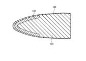
- FIG. 6 is a longitudinal sectional view of the plug 100.
- the longitudinal sectional view means a section including the central axis CL of the plug 100.
- the transverse shape of the outer peripheral surface of the plug 100 is a circle.
- the outer diameter of the plug 100 is larger at the rear end portion of the plug 100 than at the front end portion of the plug 100.
- the plug 100 has a bullet shape.
- the outer diameter of the plug 100 gradually increases from the front end toward the rear end.
- the plug 100 includes a plug body 101, a built-up layer 102, and a thermal spray coating 103.
- a built-up layer 102 is formed on the front portion of the plug body 101.
- the “front portion” of the plug body 101 means a portion between the center of the entire length of the plug 100 and the tip of the plug 100.
- the front portion of the plug 100 has a tapered shape.
- the material of the plug body 101 is not particularly limited.
- the material of the plug body 101 may be the same as a known plug material.
- the overlay layer 102 is formed on the surface of the plug body 101 around the axis of the plug body 101 (around the center axis CL).
- the overlay layer 102 is formed at the front portion of the plug body 101 and has a tapered surface inclined with respect to the central axis CL.
- the tapered surface of the built-up layer 102 is referred to as a tapered surface.
- the build-up layer 102 may be formed on the entire front part of the plug body 101 or may be formed on a part of the front part.
- the build-up layer 102 is formed by, for example, a known build-up welding method such as a plasma powder build-up welding (PTA: Plasma Transferred Arc) method, a MIG (Metal Inert Gas) welding method, or a TIG (Tungsten Insert Gas) welding method. .
- PTA Plasma Transferred Arc
- MIG Metal Inert Gas
- TIG Tungsten Insert Gas
- the cladding layer 102 contains an alloy containing a transition metal as a main component (for example, 50% or more).
- the built-up layer 102 in the present embodiment contains hard particles in addition to a matrix metal that is an alloy mainly composed of a transition metal.
- the matrix metal is, for example, a Co-based alloy, Ni-based alloy, Fe-based alloy, or the like.
- the Co-based alloy is, for example, Stellite (registered trademark). Stellite is excellent in heat resistance and ductility.
- Examples of the Ni-based alloy include IN625, C276, 50Cr-50Ni, Colmonoy (registered trademark), and the like.
- the Fe-based alloy include stainless steel, tool steel, carbon steel, and Cr steel.
- the hard particles are, for example, carbides, oxides, nitrides, borides, mixtures thereof, or composite compounds thereof.
- the hard particles are, for example, niobium carbide (NbC), tungsten carbide (WC), titanium carbide (TiC), vanadium carbide (VC), chromium carbide (Cr 3 C 2 ), and the like.
- the hard particles are oxides, the hard particles are, for example, alumina (Al 2 O 3 ), zirconia (ZrO 2 ), or the like.
- the hard particles are nitrides, the hard particles are, for example, silicon nitride (Si 3 N 4 ). Hard particles are not necessarily required, and a built-up layer that does not contain hard particles may be formed on the plug body 101.
- the thickness of the overlay layer 102 is not particularly limited.
- the thickness of the built-up layer 102 is preferably 1 to 20 mm, more preferably 2 to 10 mm.
- the thermal spray coating 103 is formed on the surface of the overlay layer 102. As shown in FIG. 6, the thermal spray coating 103 is also formed on the second surface region 1012 behind the first surface region 1011 on which the build-up layer 102 is formed, of the surface of the plug body 101.
- the sprayed coating 103 formed on the overlay layer 102 is referred to as a first sprayed region 1031 and the sprayed coating 103 formed on the second surface region 1012 is referred to as the second sprayed region 1032 as necessary. Called.
- the surface of the build-up layer 102 and the second surface region 1012 are smoothly connected without a step. Therefore, the first sprayed region 1031 is smoothly connected to the second sprayed region 1032 without a step.
- the thermal spray coating 103 is formed by a known thermal spraying method such as arc spraying, plasma spraying, flame spraying, and high-speed flame spraying.
- the material of the thermal spray coating 103 is not particularly limited.
- the material of the thermal spray coating 103 is, for example, metal, ceramic, cermet or the like.
- the thermal spray coating 103 preferably contains a metal matrix made of metal and a metal oxide.
- the metal oxide include W oxide, Ti oxide, and Fe oxide.
- the thermal spray coating 103 more preferably contains a metal matrix made of iron (Fe) and an iron oxide.
- the iron oxide is, for example, Fe 3 O 4 or FeO.
- the sprayed coating 103 is formed by, for example, arc spraying a steel wire.
- the thermal spray coating 103 has a high thermal barrier property and also has a lubricity.
- the thermal spray coating 103 is formed on the buildup layer 102, the amount of heat entering the plug body 101 from the round billet BL during piercing and rolling through the buildup layer 102 is suppressed. Therefore, the temperature rise of the plug body 101 during piercing and rolling is suppressed, and the plug body 101 is not easily deformed. As a result, the plug 100 is unlikely to be deformed as shown in FIG. 4, and the occurrence of melting and seizure is suppressed.
- the thickness T1 of the thermal spray coating 103 formed on the tip of the plug is preferably 300 to 2000 ⁇ m.
- the thickness T2 of the thermal spray coating 103 formed on the tapered surface of the build-up layer 102 is preferably 300 to 600 ⁇ m.
- the thermal spray coating 103 formed on the tapered surface of the overlay layer 102 is difficult to peel off. Therefore, heat input from the built-up layer 102 to the plug body 101 can be suppressed.
- the vertical cross-sectional shape of the taper surface of the built-up layer 102 may be a straight shape as shown in FIG. 6 or another shape.
- the longitudinal cross-sectional shape of the taper surface of the build-up layer 102 may be an arc shape having one or a plurality of curvatures, or may be another shape.
- the thermal spray coating 103 includes not only the first thermal spray region 1031 but also a second thermal spray region 1032 disposed behind the first thermal spray region 1031. Therefore, the thermal spray coating 103 effectively shields the plug 100.
- the front end of the second sprayed region 1032 is preferably adjacent to the rear end of the first sprayed region 1031. In other words, the second sprayed region 1032 extends from the rear end of the first sprayed region 1031 to the back of the plug 100. In this case, the heat shielding property of the plug 100 by the thermal spray coating 103 is further increased.
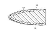
- the build-up layer 102 is formed only at the tip portion of the front portion of the plug body 101. However, as shown in FIG. 7, the build-up layer 102 may extend further behind the plug 100 than in the case of FIG. 6. Furthermore, as shown in FIG. 8, the build-up layer 102 may be formed on the entire surface except the rear end surface of the plug body 101.
- the overlay layer 102 covers the tip of the plug 100.
- the built-up layer 102 does not have to cover the tip of the plug 100. This is because, in the elongator, the hollow shell is rolled as a material, so that the material does not contact the tip of the plug 100. Therefore, for example, as shown in FIG. 9, the overlay layer 102 may be formed in an annular shape around the central axis CL at the front portion of the plug 100 without covering the tip of the plug 100.
- the thermal spray coating 103 covers the entire surface except the rear end face of the plug 100.
- the thermal spray coating 103 covers the entire overlay layer 102. In this case, heat input to the built-up layer 102 can be effectively suppressed. Further, the thermal spray coating 103 may not include the second thermal spray region 1032. Even in this case, heat input to the build-up layer 102 can be suppressed, and the temperature rise of the plug body 101 can be suppressed.
- the build-up layer 102 is formed on the front portion of the plug body 101.
- the build-up layer 102 may not be formed on the entire front portion of the plug body 101 but may be formed on a part of the front portion.
- the build-up layer 102 is formed on the plug body 101 by the above-described build-up method.
- the surface of the formed overlay layer 102 is roughened.
- shot blasting is performed on the surface of the cladding layer 102 in order to roughen the surface of the cladding layer 102 and improve the adhesion of the thermal spray coating 103.
- the thermal spray coating 103 (1031, 1032) is formed on the surface of the overlay layer 102 and, if necessary, the second surface region 1012.
- the thermal spray coating 103 is formed by arc spraying a steel wire.
- the plug 100 is manufactured through the above steps.
- plug In Table 1, all the plug bodies of the plugs of test numbers 1 to 11 have a bullet shape with a maximum outer diameter of 77 mm and a total length of 230 mm.
- the plug body had a chemical composition corresponding to the alloy tool steel material defined in JIS G4404 (2006).
- the plug of test number 1 had an oxide scale film 302 on the surface of the plug body 301 as shown in FIG. Both the thickness T1 (thickness at the plug tip position, see FIG. 6) and the thickness T2 (thickness at the taper surface position, see FIG. 6) of the oxide scale film 302 were 500 ⁇ m. In this example, the thickness T2 at the taper surface position was defined as the thickness at a position 80 mm from the plug tip.
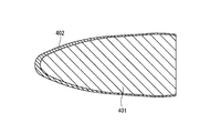
- the plug of test number 2 was provided with a thermal spray coating 402 of iron and iron oxide on the entire surface other than the rear end surface of the plug main body 401 as shown in FIG.
- the thickness T1 of the thermal spray coating 402 was 1500 ⁇ m, and the thickness T2 was 500 ⁇ m.
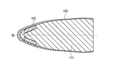
- the plugs of test numbers 3 and 4 were provided with a built-up layer 502 on the entire surface other than the rear end surface of the plug body 501 as shown in FIG.
- the thickness of the overlay layer was 2 mm. No other film was formed on the surface of the overlay layer.
- the overlay layer of test number 3 is Stellite No. It had a chemical composition corresponding to 6.
- the build-up layer of test number 4 is Stellite No. A metal matrix having a chemical composition corresponding to 6 and 50% by mass of NbC were contained.
- the plug of test number 5 is formed in a range of 50 mm from the front end to the rear end of the surface of the plug main body 201, and has a build-up layer 202 having a thickness of 5 mm, and a build-up layer 202.
- a thermal spray coating 203 having a thickness T2 of 500 ⁇ m was formed on the surface of the plug body 201 from the rear end to the rear end of the plug.
- the material of the build-up layer 202 was the same as test number 4.
- the test numbers 6 and 7 include a build-up layer 102 formed on the surface excluding the rear end face of the plug body 101, and a sprayed coating 103 formed on the entire surface of the build-up layer 102. It was.
- the material of the build-up layer 102 of test numbers 6 and 7 and the material of the thermal spray coating 103 were as shown in Table 1.
- the thickness of the build-up layer 102 of test numbers 6 and 7 was 2 mm, and the thicknesses T1 and T2 of the sprayed coating were as shown in Table 1.
- the plugs with test numbers 8 to 10 are formed in a range of 50 mm from the front end to the rear end of the plug body 101 and have a thickness of 5 mm.
- a build-up layer 102 made of a material, and a build-up layer 102 and a spray coating 103 made of the material shown in Table 1 formed on the plug body from the rear end to the plug rear end of the build-up layer 102 were provided.
- the thicknesses T1 and T2 of the sprayed coating 103 were as shown in Table 1.
- the plug of the test number 11 has a longer build-up layer 102 than the test numbers 8 to 10, and is within a range of 100 mm from the front end of the plug to the rear end on the surface of the plug body. Been formed. As shown in Table 1, the other configurations were the same as those of test numbers 8 to 10.
- a solid round billet was pierced and rolled using the plug of each test number.
- the diameter of the round billet was 65 mm and the length was 500 mm.
- the chemical composition of the round billet was 25% Cr and 50% Ni, and was a so-called high alloy chemical composition.
- Test results The test results are shown in Table 1.
- the “state” column in Table 1 describes the surface state of the plug at the end of the test.
- test numbers 6 to 11 correspond to the plugs of this embodiment.
- the number of passes was as high as 3 or more, and an excellent plug life was shown.
- the build-up layer contains stellite and NbC, no damage was observed in the plug even when the number of passes was 4, and an excellent plug life was obtained.
- test number 1 only the oxide scale was formed on the plug surface, so the number of passes was as small as 1. In the plug after piercing and rolling, the plug was deformed and the tip was melted.
- test number 2 the number of passes was as low as 2, the plug after piercing and rolling was deformed, and the tip was melted.
- Test Nos. 3 and 4 had a build-up layer formed on the entire plug surface, but the number of passes was 1 or less.
- Test No. 4 the tip portion melted and seizure occurred on the plug surface other than the tip portion. Heat is transferred from the material to the build-up layer, and as a result of excessive rise in the temperature of the plug tip, it is considered that melting damage has occurred.
- test number 5 the number of passes was as low as 1, the plug was deformed and the tip was melted. This is probably because heat was transferred from the material to the overlay layer, and the temperature at the tip of the plug increased excessively.
Landscapes
- Engineering & Computer Science (AREA)
- Chemical & Material Sciences (AREA)
- Mechanical Engineering (AREA)
- Physics & Mathematics (AREA)
- Plasma & Fusion (AREA)
- Chemical Kinetics & Catalysis (AREA)
- Materials Engineering (AREA)
- Metallurgy (AREA)
- Organic Chemistry (AREA)
- Coating By Spraying Or Casting (AREA)
- Mounting, Exchange, And Manufacturing Of Dies (AREA)
- Laminated Bodies (AREA)
Abstract
Description
本願は、2013年01月11日に、日本に出願された特願2013-003665号に基づき優先権を主張し、その内容をここに援用する。
(1)本発明の一態様に係る熱間製管用プラグは、プラグ本体と;前記プラグ本体の表面上に、前記プラグ本体の軸周りに形成される肉盛層と;前記肉盛層の表面上に形成される溶射皮膜と;を備える。
(2)上記(1)に記載の熱間製管用プラグにおいて、前記肉盛層が、前記プラグ本体の前部の表面上に形成されてもよい。また、前記肉盛層が、テーパ形状の表面を含んでもよい。さらに、前記溶射皮膜が、前記テーパ形状の表面上に形成されてもよい。
(3)上記(1)に記載の熱間製管用プラグにおいて、前記溶射皮膜が、前記肉盛層の表面全体を覆っていてもよい。
(4)上記(1)に記載の熱間製管用プラグにおいて、前記プラグ本体の表面が、前記肉盛層が形成される第1表面領域と;前記第1表面領域よりも前記プラグ本体の後方の第2表面領域と;を含んでいてもよい。また、前記溶射皮膜が、前記肉盛層の表面上に形成される第1溶射領域と;前記第2表面領域上に形成される第2溶射領域と;を含んでいてもよい。
(5)上記(4)に記載の熱間製管用プラグにおいて、前記第2溶射領域が前記第1溶射領域と隣接していてもよい。
(6)上記(1)~(5)のいずれか一つに記載の熱間製管用プラグにおいて、前記肉盛層が、前記プラグ本体の先端を覆っていてもよい。
本発明者は、プラグの寿命を向上するために、調査、検討を行い、以下の知見を得た。
本実施形態に係るプラグは、穿孔機、又は、エロンゲータに利用される。以降の説明では、穿孔機を例にプラグの説明を行う。しかしながら、エロンゲータに利用されるプラグも同様である。
図6は、プラグ100の縦断面図である。ここでいう縦断面図とは、プラグ100の中心軸CLを含む断面を意味する。
プラグ本体101の前部には、肉盛層102が形成される。本明細書において、プラグ本体101の「前部」とは、プラグ100の全長の中央とプラグ100の先端との間の部分を意味する。プラグ100の前部はテーパ形状を有する。
肉盛層102は、プラグ本体101の表面上に、プラグ本体101の軸周り(中心軸CLの周り)に形成される。肉盛層102は、プラグ本体101の前部に形成され、中心軸CLに対して傾斜するテーパ形状の表面を有する。以下、肉盛層102のテーパ形状の表面をテーパ表面という。肉盛層102は、プラグ本体101の前部の全体に形成されてもよいし、前部のうちの一部に形成されてもよい。
溶射皮膜103は、肉盛層102の表面上に形成される。図6に示すように、溶射皮膜103は、プラグ本体101の表面うち、肉盛層102が形成された第1表面領域1011よりも後方の第2表面領域1012上にも形成されている。以降の説明では、必要に応じて、肉盛層102上に形成された溶射皮膜103を第1溶射領域1031と称し、第2表面領域1012上に形成された溶射皮膜103を第2溶射領域1032と称する。
プラグ100の製造方法の一例は次の通りである。

表1において、試験番号1~11のプラグのプラグ本体はいずれも、最大外径が77mm、全長が230mmの砲弾形状であった。プラグ本体は、JIS G4404(2006)に規定の合金工具鋼鋼材に相当する化学組成を有した。
試験結果を表1に示す。表1中の「状態」欄には、試験終了時のプラグの表面状態が記載されている。
1 穿孔機
100、200、300 プラグ
101、201、301、401、501 プラグ本体
102、202、502 肉盛層
103、203、402 溶射皮膜
302 酸化スケール皮膜
Claims (6)
- プラグ本体と;
前記プラグ本体の表面上に、前記プラグ本体の軸周りに形成される肉盛層と;
前記肉盛層の表面上に形成される溶射皮膜と;
を備えることを特徴とする熱間製管用プラグ。 - 前記肉盛層は、前記プラグ本体の前部の表面上に形成され、
前記肉盛層は、テーパ形状の表面を含み、
前記溶射皮膜は、前記テーパ形状の表面上に形成される、
ことを特徴とする請求項1に記載の熱間製管用プラグ。 - 前記溶射皮膜は、前記肉盛層の表面全体を覆うことを特徴とする請求項1に記載の熱間製管用プラグ。
- 前記プラグ本体の表面は、
前記肉盛層が形成される第1表面領域と;
前記第1表面領域よりも前記プラグ本体の後方の第2表面領域と;
を含み、
前記溶射皮膜は、
前記肉盛層の表面上に形成される第1溶射領域と;
前記第2表面領域上に形成される第2溶射領域と;
を含むことを特徴とする請求項1に記載の熱間製管用プラグ。 - 前記第2溶射領域は前記第1溶射領域と隣接することを特徴とする請求項4に記載の熱間製管用プラグ。
- 前記肉盛層は、前記プラグ本体の先端を覆うことを特徴とする請求項1~5のいずれか一項に記載の熱間製管用プラグ。
Priority Applications (6)
| Application Number | Priority Date | Filing Date | Title |
|---|---|---|---|
| JP2014509557A JP5610101B1 (ja) | 2013-01-11 | 2013-12-16 | 熱間製管用プラグ |
| US14/433,154 US9352370B2 (en) | 2013-01-11 | 2013-12-16 | Plug for hot tube-making |
| BR112015008558-0A BR112015008558B1 (pt) | 2013-01-11 | 2013-12-16 | tampão para a produção de tubo a quente |
| CN201380055291.8A CN104736262A (zh) | 2013-01-11 | 2013-12-16 | 热制管用顶头 |
| MX2015005227A MX354718B (es) | 2013-01-11 | 2013-12-16 | Tapón para manufactura de tubos para calor. |
| EP13870430.9A EP2944387B1 (en) | 2013-01-11 | 2013-12-16 | Plug for hot pipe manufacturing |
Applications Claiming Priority (2)
| Application Number | Priority Date | Filing Date | Title |
|---|---|---|---|
| JP2013003665 | 2013-01-11 | ||
| JP2013-003665 | 2013-01-11 |
Publications (1)
| Publication Number | Publication Date |
|---|---|
| WO2014109180A1 true WO2014109180A1 (ja) | 2014-07-17 |
Family
ID=51166840
Family Applications (1)
| Application Number | Title | Priority Date | Filing Date |
|---|---|---|---|
| PCT/JP2013/083635 Ceased WO2014109180A1 (ja) | 2013-01-11 | 2013-12-16 | 熱間製管用プラグ |
Country Status (8)
| Country | Link |
|---|---|
| US (1) | US9352370B2 (ja) |
| EP (1) | EP2944387B1 (ja) |
| JP (1) | JP5610101B1 (ja) |
| CN (1) | CN104736262A (ja) |
| AR (1) | AR094371A1 (ja) |
| BR (1) | BR112015008558B1 (ja) |
| MX (1) | MX354718B (ja) |
| WO (1) | WO2014109180A1 (ja) |
Cited By (3)
| Publication number | Priority date | Publication date | Assignee | Title |
|---|---|---|---|---|
| JPWO2016129019A1 (ja) * | 2015-02-09 | 2017-10-12 | 新日鐵住金株式会社 | プラグの製造方法 |
| WO2018029926A1 (ja) * | 2016-08-08 | 2018-02-15 | 新日鐵住金株式会社 | ピアサープラグの製造方法 |
| EP3017888B1 (de) | 2014-11-07 | 2019-04-24 | Hua Guo | Warmumformungswerkzeug |
Families Citing this family (3)
| Publication number | Priority date | Publication date | Assignee | Title |
|---|---|---|---|---|
| BR112017028179B1 (pt) * | 2015-09-28 | 2023-02-07 | Nippon Steel Corporation | Pino e método para sua fabricação |
| DE102021128128A1 (de) | 2021-10-28 | 2023-05-04 | Vallourec Deutschland Gmbh | Lochdorn mit einer Lochdornnase zur Herstellung nahtloser Rohre |
| CN116393515B (zh) * | 2023-06-09 | 2023-08-04 | 太原理工大学 | 一种无缝金属复合管界面热力可控连续轧制设备及方法 |
Citations (15)
| Publication number | Priority date | Publication date | Assignee | Title |
|---|---|---|---|---|
| JPS61286077A (ja) * | 1985-06-12 | 1986-12-16 | Nippon Steel Corp | 鋼管圧延機用芯金 |
| JPS62183950A (ja) * | 1986-02-06 | 1987-08-12 | Nippon Steel Corp | 熱鋼片処理用溶射ロ−ル |
| JPS63203205A (ja) | 1987-02-17 | 1988-08-23 | Sumitomo Metal Ind Ltd | 穿孔機用プラグ |
| JPH03193204A (ja) * | 1989-12-25 | 1991-08-23 | Sumitomo Metal Ind Ltd | 熱間継目無管製造用プラグ |
| JPH048498B2 (ja) | 1987-05-12 | 1992-02-17 | ||
| JPH0474848A (ja) | 1990-07-13 | 1992-03-10 | Sumitomo Metal Ind Ltd | 熱間製管工具用鋼及び熱間製管工具 |
| JPH04270003A (ja) | 1991-02-23 | 1992-09-25 | Sumitomo Metal Ind Ltd | 熱間製管工具及びその製造方法 |
| JPH0575575B2 (ja) | 1988-07-22 | 1993-10-20 | Toho Rayon Kk | |
| JPH07147B2 (ja) | 1988-06-13 | 1995-01-11 | 株式会社タカラ | 音出し玩具 |
| JP2776266B2 (ja) | 1994-08-26 | 1998-07-16 | 住友金属工業株式会社 | 熱間加工用複合被膜形成工具 |
| JPH10306383A (ja) * | 1997-03-07 | 1998-11-17 | Sumitomo Metal Ind Ltd | 複合材及びその製造方法 |
| JP2000033512A (ja) * | 1998-07-16 | 2000-02-02 | Toshiba Mach Co Ltd | 超硬工具およびその表面処理方法 |
| JP2005014558A (ja) * | 2003-06-30 | 2005-01-20 | Toshiba Corp | 積層金型の製造方法 |
| JP2009101408A (ja) * | 2007-10-25 | 2009-05-14 | Nkktubes Kk | 高温加工用工具 |
| JP4279350B1 (ja) | 2007-11-01 | 2009-06-17 | 住友金属工業株式会社 | 穿孔圧延用プラグ、その穿孔圧延用プラグの再生方法、およびその穿孔圧延用プラグの再生設備列 |
Family Cites Families (15)
| Publication number | Priority date | Publication date | Assignee | Title |
|---|---|---|---|---|
| US2392821A (en) * | 1944-01-22 | 1946-01-15 | Haynes Sellite Company | Metal-working tool |
| JPS5913924B2 (ja) * | 1979-12-25 | 1984-04-02 | 日本鋼管株式会社 | 穿孔圧延機用芯金 |
| CA1173123A (en) | 1981-02-27 | 1984-08-21 | Charles C. Rayburn | Capacitor and method for making the same |
| JPS647147A (en) | 1987-06-29 | 1989-01-11 | Nec Corp | Data processing device |
| JPH02224806A (ja) * | 1989-02-28 | 1990-09-06 | Nkk Corp | 継目無し鋼管製造用プラグ |
| JPH048498A (ja) | 1990-04-20 | 1992-01-13 | Nec Kansai Ltd | シート積層体の切断方法 |
| JP2543445Y2 (ja) * | 1990-11-08 | 1997-08-06 | ソニー株式会社 | ランプ装置 |
| JPH04279350A (ja) | 1991-03-08 | 1992-10-05 | Fuji Electric Co Ltd | 記録ヘッドの異常装着検知装置 |
| US5778714A (en) * | 1995-05-19 | 1998-07-14 | Nkk Corporation | Method for manufacturing seamless pipe |
| JPH10180315A (ja) * | 1996-12-27 | 1998-07-07 | Kawasaki Steel Corp | 継目無鋼管圧延用プラグおよび継目無鋼管の製造方法 |
| EP1728566B1 (en) * | 2004-03-11 | 2012-08-29 | Sumitomo Metal Industries, Ltd. | Seamless pipe producing device and seamless pipe producing method using them |
| UA97027C2 (uk) * | 2007-11-01 | 2011-12-26 | Сумитомо Мэтал Индастриз, Лтд. | Прошивна і прокатна оправка, спосіб відновлення цієї прошивної і прокатної оправки і технологічна лінія для відновлення цієї прошивної і прокатної оправки |
| JP5169982B2 (ja) * | 2009-03-03 | 2013-03-27 | 新日鐵住金株式会社 | プラグ、穿孔圧延機、およびそれを用いた継目無管の製造方法 |
| CN102284777A (zh) * | 2010-06-17 | 2011-12-21 | 上海宝钢设备检修有限公司 | 无缝钢管穿孔机顶头表面堆焊强化的方法 |
| JP5365724B2 (ja) * | 2012-04-24 | 2013-12-11 | 新日鐵住金株式会社 | 穿孔圧延用プラグの製造設備 |
-
2013
- 2013-12-16 CN CN201380055291.8A patent/CN104736262A/zh active Pending
- 2013-12-16 BR BR112015008558-0A patent/BR112015008558B1/pt active IP Right Grant
- 2013-12-16 JP JP2014509557A patent/JP5610101B1/ja active Active
- 2013-12-16 MX MX2015005227A patent/MX354718B/es active IP Right Grant
- 2013-12-16 US US14/433,154 patent/US9352370B2/en active Active
- 2013-12-16 EP EP13870430.9A patent/EP2944387B1/en active Active
- 2013-12-16 WO PCT/JP2013/083635 patent/WO2014109180A1/ja not_active Ceased
-
2014
- 2014-01-06 AR ARP140100040A patent/AR094371A1/es active IP Right Grant
Patent Citations (16)
| Publication number | Priority date | Publication date | Assignee | Title |
|---|---|---|---|---|
| JPS61286077A (ja) * | 1985-06-12 | 1986-12-16 | Nippon Steel Corp | 鋼管圧延機用芯金 |
| JPS62183950A (ja) * | 1986-02-06 | 1987-08-12 | Nippon Steel Corp | 熱鋼片処理用溶射ロ−ル |
| JPS63203205A (ja) | 1987-02-17 | 1988-08-23 | Sumitomo Metal Ind Ltd | 穿孔機用プラグ |
| JPH048498B2 (ja) | 1987-05-12 | 1992-02-17 | ||
| JPH07147B2 (ja) | 1988-06-13 | 1995-01-11 | 株式会社タカラ | 音出し玩具 |
| JPH0575575B2 (ja) | 1988-07-22 | 1993-10-20 | Toho Rayon Kk | |
| JPH03193204A (ja) * | 1989-12-25 | 1991-08-23 | Sumitomo Metal Ind Ltd | 熱間継目無管製造用プラグ |
| JPH0474848A (ja) | 1990-07-13 | 1992-03-10 | Sumitomo Metal Ind Ltd | 熱間製管工具用鋼及び熱間製管工具 |
| JPH04270003A (ja) | 1991-02-23 | 1992-09-25 | Sumitomo Metal Ind Ltd | 熱間製管工具及びその製造方法 |
| JP2776266B2 (ja) | 1994-08-26 | 1998-07-16 | 住友金属工業株式会社 | 熱間加工用複合被膜形成工具 |
| JPH10306383A (ja) * | 1997-03-07 | 1998-11-17 | Sumitomo Metal Ind Ltd | 複合材及びその製造方法 |
| JP3891679B2 (ja) | 1997-03-07 | 2007-03-14 | 住友金属工業株式会社 | 継目無鋼管穿孔圧延用プラグ及びその製造方法 |
| JP2000033512A (ja) * | 1998-07-16 | 2000-02-02 | Toshiba Mach Co Ltd | 超硬工具およびその表面処理方法 |
| JP2005014558A (ja) * | 2003-06-30 | 2005-01-20 | Toshiba Corp | 積層金型の製造方法 |
| JP2009101408A (ja) * | 2007-10-25 | 2009-05-14 | Nkktubes Kk | 高温加工用工具 |
| JP4279350B1 (ja) | 2007-11-01 | 2009-06-17 | 住友金属工業株式会社 | 穿孔圧延用プラグ、その穿孔圧延用プラグの再生方法、およびその穿孔圧延用プラグの再生設備列 |
Non-Patent Citations (1)
| Title |
|---|
| See also references of EP2944387A4 |
Cited By (6)
| Publication number | Priority date | Publication date | Assignee | Title |
|---|---|---|---|---|
| EP3017888B1 (de) | 2014-11-07 | 2019-04-24 | Hua Guo | Warmumformungswerkzeug |
| JPWO2016129019A1 (ja) * | 2015-02-09 | 2017-10-12 | 新日鐵住金株式会社 | プラグの製造方法 |
| US20180023179A1 (en) * | 2015-02-09 | 2018-01-25 | Nippon Steel & Sumitomo Metal Corporation | Method for Producing Plug |
| WO2018029926A1 (ja) * | 2016-08-08 | 2018-02-15 | 新日鐵住金株式会社 | ピアサープラグの製造方法 |
| JPWO2018029926A1 (ja) * | 2016-08-08 | 2018-11-08 | 新日鐵住金株式会社 | ピアサープラグの製造方法 |
| US10888906B2 (en) | 2016-08-08 | 2021-01-12 | Nippon Steel & Sumitomo Metal Corporation | Method of manufacturing piercer plug |
Also Published As
| Publication number | Publication date |
|---|---|
| MX354718B (es) | 2018-03-16 |
| JPWO2014109180A1 (ja) | 2017-01-19 |
| US20150258591A1 (en) | 2015-09-17 |
| CN104736262A (zh) | 2015-06-24 |
| EP2944387A1 (en) | 2015-11-18 |
| US9352370B2 (en) | 2016-05-31 |
| EP2944387A4 (en) | 2016-07-27 |
| AR094371A1 (es) | 2015-07-29 |
| MX2015005227A (es) | 2015-07-14 |
| BR112015008558A2 (pt) | 2017-07-04 |
| JP5610101B1 (ja) | 2014-10-22 |
| EP2944387B1 (en) | 2019-08-07 |
| BR112015008558B1 (pt) | 2021-02-09 |
Similar Documents
| Publication | Publication Date | Title |
|---|---|---|
| JP5610101B1 (ja) | 熱間製管用プラグ | |
| JP5464300B1 (ja) | 穿孔機に用いられるプラグ | |
| US10441982B2 (en) | Plug for rolling of seamless steel pipe, method for manufacturing the same and method for manufacturing seamless steel pipe using the same | |
| JP5435184B1 (ja) | 穿孔プラグ | |
| CN104245167B (zh) | 用于穿孔机的顶头的再生方法 | |
| JP5339016B1 (ja) | 穿孔圧延用プラグの製造方法 | |
| JP3891679B2 (ja) | 継目無鋼管穿孔圧延用プラグ及びその製造方法 | |
| JP5075575B2 (ja) | 高温加工用工具 | |
| EP3257596B1 (en) | Method for producing plug | |
| JP6652193B2 (ja) | ピアサープラグの製造方法 | |
| JP2016047545A (ja) | 継目無鋼管穿孔圧延用プラグ | |
| JP6540441B2 (ja) | プラグの製造方法 | |
| JP6237540B2 (ja) | 継目無鋼管の製造方法 | |
| JP4736773B2 (ja) | 継目無鋼管の製造方法 | |
| JPH01289504A (ja) | 鋼管穿孔機用プラグ |
Legal Events
| Date | Code | Title | Description |
|---|---|---|---|
| ENP | Entry into the national phase |
Ref document number: 2014509557 Country of ref document: JP Kind code of ref document: A |
|
| 121 | Ep: the epo has been informed by wipo that ep was designated in this application |
Ref document number: 13870430 Country of ref document: EP Kind code of ref document: A1 |
|
| WWE | Wipo information: entry into national phase |
Ref document number: 14433154 Country of ref document: US |
|
| WWE | Wipo information: entry into national phase |
Ref document number: 2013870430 Country of ref document: EP |
|
| WWE | Wipo information: entry into national phase |
Ref document number: MX/A/2015/005227 Country of ref document: MX |
|
| REG | Reference to national code |
Ref country code: BR Ref legal event code: B01A Ref document number: 112015008558 Country of ref document: BR |
|
| NENP | Non-entry into the national phase |
Ref country code: DE |
|
| ENP | Entry into the national phase |
Ref document number: 112015008558 Country of ref document: BR Kind code of ref document: A2 Effective date: 20150416 |
|
| REG | Reference to national code |
Ref country code: BR Ref legal event code: B01E Ref document number: 112015008558 Country of ref document: BR Kind code of ref document: A2 Free format text: APRESENTE A TRADUCAO SIMPLES DA FOLHA DE ROSTO DA CERTIDAO DE DEPOSITO DA PRIORIDADE JP 2013-003665; OU DECLARACAO DE QUE OS DADOS DO PEDIDO INTERNACIONAL ESTAO FIELMENTE CONTIDOS NA PRIORIDADE REIVINDICADA, CONTENDO TODOS OS DADOS IDENTIFICADORES DESTA (TITULARES, NUMERO DE REGISTRO, DATA E TITULO), CONFORME O PARAGRAFO UNICO DO ART. 25 DA RESOLUCAO 77/2013. CABESALIENTAR QUE NAO FOI POSSIVEL IDENTIFICAR OS TITULARES DO PEDIDO PRIORITARIO NOS DOCUMENTOS JUNTADOS AO PROCESSO, TAMPOUCO NOS APRESENTADOS NA OMPI, POIS SE ENCONTRAM EM JAPONES. |
|
| REG | Reference to national code |
Ref country code: BR Ref legal event code: B01Y Ref document number: 112015008558 Country of ref document: BR Kind code of ref document: A2 Free format text: ANULADA A PUBLICACAO CODIGO 1.5 NA RPI NO 2540 DE 10/09/2019 POR TER SIDO INDEVIDA. |
|
| ENPC | Correction to former announcement of entry into national phase, pct application did not enter into the national phase |
Ref document number: 112015008558 Country of ref document: BR Kind code of ref document: A2 Free format text: ANULADA A PUBLICACAO CODIGO 1.3.2 NA RPI NO 2539 DE 03/09/2019 POR TER SIDO INDEVIDA. |