WO2014115278A1 - 同期電動機 - Google Patents
同期電動機 Download PDFInfo
- Publication number
- WO2014115278A1 WO2014115278A1 PCT/JP2013/051421 JP2013051421W WO2014115278A1 WO 2014115278 A1 WO2014115278 A1 WO 2014115278A1 JP 2013051421 W JP2013051421 W JP 2013051421W WO 2014115278 A1 WO2014115278 A1 WO 2014115278A1
- Authority
- WO
- WIPO (PCT)
- Prior art keywords
- teeth
- phase
- synchronous motor
- winding
- center
- Prior art date
- Legal status (The legal status is an assumption and is not a legal conclusion. Google has not performed a legal analysis and makes no representation as to the accuracy of the status listed.)
- Ceased
Links
Images





Classifications
-
- H—ELECTRICITY
- H02—GENERATION; CONVERSION OR DISTRIBUTION OF ELECTRIC POWER
- H02K—DYNAMO-ELECTRIC MACHINES
- H02K21/00—Synchronous motors having permanent magnets; Synchronous generators having permanent magnets
- H02K21/12—Synchronous motors having permanent magnets; Synchronous generators having permanent magnets with stationary armatures and rotating magnets
- H02K21/14—Synchronous motors having permanent magnets; Synchronous generators having permanent magnets with stationary armatures and rotating magnets with magnets rotating within the armatures
- H02K21/16—Synchronous motors having permanent magnets; Synchronous generators having permanent magnets with stationary armatures and rotating magnets with magnets rotating within the armatures having annular armature cores with salient poles
-
- H—ELECTRICITY
- H02—GENERATION; CONVERSION OR DISTRIBUTION OF ELECTRIC POWER
- H02K—DYNAMO-ELECTRIC MACHINES
- H02K1/00—Details of the magnetic circuit
- H02K1/06—Details of the magnetic circuit characterised by the shape, form or construction
- H02K1/12—Stationary parts of the magnetic circuit
- H02K1/14—Stator cores with salient poles
- H02K1/146—Stator cores with salient poles consisting of a generally annular yoke with salient poles
-
- H—ELECTRICITY
- H02—GENERATION; CONVERSION OR DISTRIBUTION OF ELECTRIC POWER
- H02K—DYNAMO-ELECTRIC MACHINES
- H02K3/00—Details of windings
- H02K3/04—Windings characterised by the conductor shape, form or construction, e.g. with bar conductors
- H02K3/28—Layout of windings or of connections between windings
-
- H—ELECTRICITY
- H02—GENERATION; CONVERSION OR DISTRIBUTION OF ELECTRIC POWER
- H02K—DYNAMO-ELECTRIC MACHINES
- H02K2213/00—Specific aspects, not otherwise provided for and not covered by codes H02K2201/00 - H02K2211/00
- H02K2213/03—Machines characterised by numerical values, ranges, mathematical expressions or similar information
Definitions
- the present invention relates to a synchronous motor.
- the number of poles can be increased without making the arrangement of teeth wound around the stator winding uniform.
- a technique for making it non-uniform according to the combination of the number of slots is known (for example, Patent Documents 3 to 5).
- the present invention has been made in view of the above, and an object of the present invention is to provide a synchronous motor that can achieve high performance and high efficiency in a 10-pole, 9-slot synchronous motor with high output and high efficiency. .
- the synchronous motor according to the present invention is formed by forming nine teeth on an annular iron core centered on the shaft center at equal angular intervals in the circumferential direction toward the shaft center.
- 10 pole-oriented permanent magnets formed at equal angular intervals in the circumferential direction by alternately arranging magnetic poles of different polarities on the outer peripheral surface with the shaft center as the center, and arranged opposite to the stator
- Each of the teeth is divided into three adjacent three phases, and each of the teeth for one phase has a stator winding of each phase between the adjacent teeth.
- the width is configured to be larger than 32 ° and smaller than 40 °. It is characterized in.
- a 10-pole, 9-slot synchronous motor can achieve high output, high efficiency, and high performance.
- FIG. 1 is a cross-sectional view of a synchronous motor according to an embodiment.
- FIG. 2 is a diagram illustrating a positional relationship between each tooth and magnetic pole for one phase of the synchronous motor according to the embodiment.
- FIG. 3 is a diagram illustrating an example in which the center of the teeth coincides with the center of the magnetic pole.
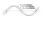
- FIG. 4 is a diagram showing an induced voltage of the stator winding wound around each tooth for one phase.
- FIG. 5 is a diagram showing calculation results for obtaining the short-pitch coefficient Kp, the distributed winding coefficient Kd, and the winding coefficient Kw using the tip widths ⁇ 1 and ⁇ 2 of the teeth of each phase as parameters.
- FIG. 6 is a diagram showing a winding coefficient ratio and an induced voltage ratio based on a case where the tip width ⁇ 1 of the teeth at the center of each phase is 40 °.
- FIG. 1 is a cross-sectional view of a synchronous motor according to an embodiment.
- FIG. 1 in the present embodiment, an example in the case of a synchronous motor using a rotor 4 in which a permanent magnet is arranged facing the inner peripheral surface of the stator 1 will be described.
- the stator 1 includes an annular iron core centered on an axial center and nine protruding iron cores (hereinafter referred to as “teeth”) 2a, 2b, 2c spaced equidistantly in the circumferential direction toward the axis (machine (Angle 40 °).
- teeth nine protruding iron cores
- Each tooth 2a, 2b, 2c is divided into three adjacent three phases (U phase, V phase, W phase).
- variety of the part which opposes the rotor 4 of each teeth 2a, 2b, 2c is hereafter called "tip width".
- the rotor 4 has ten-pole permanent magnets 6 at equiangular intervals (mechanical angle 36 °) in the circumferential direction by alternating magnetic poles of different polarities on the outer peripheral surface of a columnar back yoke 5 centered on the axis. It arrange
- FIG. 2 is a diagram illustrating a positional relationship between each tooth and magnetic pole for one phase of the synchronous motor according to the embodiment.
- Stator windings 3 of each phase are continuously wound by concentrated winding on each of the teeth 2a, 2b, 2c for one phase, and the stator winding 3 is wound around each adjacent tooth in each phase.
- the winding directions are opposite to each other when viewed from the axial center.
- the tip width of the teeth 2a located in the center for each phase is ⁇ 1
- the tip widths of the teeth 2b and 2c located at both ends are ⁇ 2.
- FIG. 3 is a diagram illustrating an example in which the center of the teeth coincides with the center of the magnetic pole.
- FIG. 4 is a figure which shows the induced voltage of the stator winding wound around each tooth for 1 phase.
- winding coefficient Kw As an index indicating how effectively the magnetic flux generated from the permanent magnet of the rotor is linked to the stator winding, there is a coefficient generally called “winding coefficient Kw”.
- the winding coefficient Kw is obtained by the product of the short-pitch winding coefficient Kp and the distributed winding coefficient Kd.
- the short-pitch winding coefficient Kp is calculated from the width of the magnetic pole of the rotor and the width of the tip of the stator teeth.
- This short-pitch winding coefficient Kp is a coefficient indicating how much the magnetic flux passes through the teeth around which the stator winding is wound, assuming that magnetic flux is generated in a sinusoidal shape from one magnetic pole of the rotor. Yes, it is calculated from the width (angle) of one magnetic pole of the rotor and the tip width (angle) of the teeth using the following equation (1).
- this short winding coefficient Kp is 1 which is the maximum value when the tip width of the teeth and the width of the magnetic pole are equal.
- a part of the magnetic flux passing through the teeth does not interlink with the stator winding, but passes through the tip portion of the teeth and is adjacent to the magnetic pole. Since the short winding coefficient Kp is reduced, the magnetic flux generated from the magnetic pole is linked to the stator winding even when the tip width of the tooth is smaller than the width of the magnetic pole. Therefore, the short winding coefficient Kp becomes small.
- the distributed winding coefficient Kd is such that, when the phase of the induced voltage generated in each stator winding wound around each tooth of the same phase is shifted, the amplitude of the induced voltage is simply set in each stator winding. This is a coefficient for correcting that the sum of induced voltages is not obtained, and is generally calculated using the following equation (2).
- the stator windings of each phase As for the positional relationship with the magnetic pole, the distributed winding coefficient Kd is 1 because the phase of the induced voltage generated in each stator winding constituting each phase does not shift only by repeating the same arrangement.
- the distributed winding coefficient Kd obtained by the above equation (2) is a coefficient calculated on the assumption that the teeth of the stator are arranged at equal intervals and the tip widths of all the teeth are the same.
- the winding coefficient Kw cannot be calculated using the above equation (2).
- the induced voltage generated in each of the wound stator windings is based on the induced voltage generated in the stator winding 3 of each phase center tooth 2a. , 2c, the phase of the induced voltage generated in the windings is shifted by 40 ° in electrical angle.
- the sum of the induced voltages generated in the stator windings 3 wound around the teeth 2a, 2b, 2c is the induced voltage generated in the stator windings 3 wound around the teeth 2a, 2b, 2c.
- ⁇ d is the phase of the induced voltage generated in the stator winding 3 of the teeth 2b and 2c at both ends of each phase with respect to the phase of the induced voltage generated in the stator winding 3 of the tooth 2a at the center of each phase.
- the phase difference is shown.
- the induced voltage generated in the stator winding 3 of each tooth 2b, 2c at both ends of each phase becomes smaller, and the induction generated in the stator winding 3 of each tooth 2a, 2b, 2c.
- the synthesized value of the voltage is also reduced.
- the winding coefficient Kw1 of the stator winding 3 wound around the teeth 2a at the center of each phase is expressed by the following equation (1), where the short-pitch winding coefficient is Kp1 and the distributed winding coefficient is Kd1. From the equation (3), it is as follows.
- Kw1 Kp1 ⁇
- the winding coefficient Kw2 of the stator winding 3 wound around each of the teeth 2b and 2c at both ends of each phase has a short-pitch coefficient Kp2 and a distributed winding coefficient Kd2. From the equations (1) and (3), the following is obtained.
- FIG. 5 is a diagram showing calculation results for obtaining the short-pitch winding coefficient Kp, the distributed winding coefficient Kd, and the winding coefficient Kw using the tip widths ⁇ 1 and ⁇ 2 of the teeth of each phase as parameters.
- FIG. 6 is a diagram showing the winding coefficient ratio and the induced voltage ratio based on the case where the tip width ⁇ 1 of the teeth at the center of each phase is 40 °.
- the solid line shown in FIG. 6 calculates the winding coefficient Kw using the above equation (4), and the winding coefficient based on the winding coefficient Kw when the tip width ⁇ 1 of the teeth at the center of each phase is 40 °. 6 shows the ratio, and the diamond symbol (6) shown in FIG.
- the calculation result of the winding coefficient Kw at this time is 0.9452, as shown in FIG.
- the winding coefficient Kw gradually increases as the tip width ⁇ 1 of the teeth at the center of each phase decreases from 40 °, and the winding coefficient Kw becomes the maximum. This is a case where the tip width ⁇ 1 of the teeth in the center of the phase is 36 ° ( ⁇ 2 is 42 °), which is 0.9553 as shown in FIG.
- each tooth is equiangular and the tip widths ⁇ 1 and ⁇ 2 of each tooth in each phase are equal.
- the winding coefficient Kw is larger than that of a 10-pole 9-slot synchronous motor. As shown in FIG. 6, the winding coefficient ratio obtained by the above equation (4) is almost the same as the induced voltage ratio obtained by magnetic field analysis, and the tip width ⁇ 1 of the teeth at the center of each phase is 36 °. In some cases, the induced voltage is up to about 1% higher.
- the tip width ⁇ 1 of the center tooth 2a of each phase is configured to satisfy 32 ° ⁇ 1 ⁇ 40 °.
- the tip width ⁇ 1 of the teeth 2a at the center of each phase is set to approximately 36 °, which is the maximum compared to a general 10-pole 9-slot synchronous motor.
- An induced voltage that is about 1% larger can be obtained, and higher output and higher efficiency can be achieved.
- the winding coefficient Kw1 of the stator winding wound around the teeth at the center of each phase is the stator winding wound around the teeth at both ends of each phase. Since the winding coefficient Kw2 of each tooth is higher than the winding coefficient Kw2, the width of the portion where the stator winding of each tooth is wound is made non-uniform according to the tip width of each tooth, and the teeth at the center of each phase When the part where the stator windings of the teeth at both ends of each phase are wound closer to each other, the cross-sectional area of the slot between the teeth at the center of each phase and the teeth at both ends of each phase decreases, and the stator can be stored in the slot Since there are fewer windings, the performance of the synchronous motor cannot be fully exploited.
- the teeth 2a, 2b, 2c are arranged at equal angular intervals, and the tip widths of the teeth 2b, 2c at both ends of each phase are the same ⁇ 2.
- harmonic components which are distortions included in the induced voltage generated in the stator windings of the teeth, cancel each other out.
- the distortion of the induced voltage can be reduced.
- the largest winding coefficient can be theoretically obtained by increasing the slot opening between the phases and making the tip widths of the teeth close to 36 ° (distribution).
- the center of each phase By configuring so that the tip width ⁇ 1 of the teeth satisfies 32 ° ⁇ 1 ⁇ 40 °, an induced voltage larger than that of a general 10-pole 9-slot synchronous motor can be obtained.
- a current equivalent to that of the synchronous motor is supplied, higher torque can be obtained, so that higher output can be achieved.
- the induced voltage is about 1% higher than that of a general 10-pole 9-slot synchronous motor.
- higher output and higher efficiency can be achieved.
- the configuration shown in the above embodiment is an example of the configuration of the present invention, and can be combined with another known technique, and a part thereof is omitted without departing from the gist of the present invention. Needless to say, it is possible to change the configuration.
- the synchronous motor according to the present invention is useful for a three-phase synchronous motor using a permanent magnet, and is particularly suitable for a synchronous motor having a 10-pole 9-slot configuration.
- stator 1 stator, 2a, 2b, 2c teeth, 3 stator winding, 4 rotor, 5 back yoke, 6 permanent magnet.
Landscapes
- Engineering & Computer Science (AREA)
- Power Engineering (AREA)
- Iron Core Of Rotating Electric Machines (AREA)
- Permanent Magnet Type Synchronous Machine (AREA)
Abstract
Description
図1は、実施の形態にかかる同期電動機の横断面図である。図1に示すように、本実施の形態では、固定子1の内周面に対向して永久磁石を配置した回転子4を用いた同期電動機である場合の例について説明する。
=sin(π/2×(ティースの先端幅)/(磁極の幅)) …(1)
(q=(スロット数)/(極数)/3)
=sin(2π×θ1/36°)
Kd1=cos(π×0°/180°)=1
Kw1=Kp1×Kd1
=Kp1
=sin(2π×θ1/36°)
=sin(2π×((120°-θ1)/2)/36°)
=sin(2π×(60°-θ1/2)/36°)
Kd2=cos(π×((θ1/2+θ2/2)×(極対数)-180°)
/180°)
=cos(π×(30°-θ1/4)/180°)
Kw2=Kp2×Kd2
=(sin(2π×(60°-θ1/2)/36°)
×cos(π×(30°-θ1/4)/180°))
=(sin(2π×θ1/36°)
+2(sin(2π×(60°-θ1/2)/36°)
×cos(π×(30°-θ1/4)/180°)))/3 …(4)
Claims (4)
- 軸心を中心とする円環状の鉄心に9個のティースが軸心に向かって周方向に等角度間隔で形成された固定子と、
軸心を中心として外周面に異なる極性の磁極を交互にして周方向に等角度間隔で形成された10極の永久磁石が配置され、前記固定子に対向配置された回転子と、
を備え、
前記各ティースは、隣り合う3個ずつの3相に区分され、1相分の前記各ティースには、隣接する前記各ティース間で各相の固定子巻線の巻回方向が軸心から見て互いに逆方向となるように連続して集中巻きで巻回され、各相の前記各ティースのうち、各相中央のティースの前記回転子に対向する先端部の幅が32°よりも大きく、40°よりも小さくなるように構成されたことを特徴とする同期電動機。 - 各相の前記各ティースのうち、前記回転子に対向する各相中央のティースの先端部の幅が略36°であることを特徴とする請求項1に記載の同期電動機。
- 各相の前記各ティースのうち、前記回転子に対向する各相両端のティースの先端部の幅が等しいことを特徴とする請求項1乃至2に記載の同期電動機。
- 前記各ティース間のスロット開口部の幅が略同一幅であることを特徴とする請求項3に記載の同期電動機。
Priority Applications (5)
| Application Number | Priority Date | Filing Date | Title |
|---|---|---|---|
| PCT/JP2013/051421 WO2014115278A1 (ja) | 2013-01-24 | 2013-01-24 | 同期電動機 |
| CN201380068813.8A CN104885345B (zh) | 2013-01-24 | 2013-01-24 | 同步电动机 |
| EP13872806.8A EP2950431B1 (en) | 2013-01-24 | 2013-01-24 | Synchronous electric motor |
| US14/655,766 US9800099B2 (en) | 2013-01-24 | 2013-01-24 | Synchronous motor |
| JP2014558363A JP6049765B2 (ja) | 2013-01-24 | 2013-01-24 | 同期電動機 |
Applications Claiming Priority (1)
| Application Number | Priority Date | Filing Date | Title |
|---|---|---|---|
| PCT/JP2013/051421 WO2014115278A1 (ja) | 2013-01-24 | 2013-01-24 | 同期電動機 |
Publications (1)
| Publication Number | Publication Date |
|---|---|
| WO2014115278A1 true WO2014115278A1 (ja) | 2014-07-31 |
Family
ID=51227094
Family Applications (1)
| Application Number | Title | Priority Date | Filing Date |
|---|---|---|---|
| PCT/JP2013/051421 Ceased WO2014115278A1 (ja) | 2013-01-24 | 2013-01-24 | 同期電動機 |
Country Status (5)
| Country | Link |
|---|---|
| US (1) | US9800099B2 (ja) |
| EP (1) | EP2950431B1 (ja) |
| JP (1) | JP6049765B2 (ja) |
| CN (1) | CN104885345B (ja) |
| WO (1) | WO2014115278A1 (ja) |
Families Citing this family (4)
| Publication number | Priority date | Publication date | Assignee | Title |
|---|---|---|---|---|
| US9923493B2 (en) * | 2014-01-09 | 2018-03-20 | Mitsubishi Electric Corporation | Drive circuit for synchronous motor, synchronous motor driven by drive circuit, air blower including synchronous motor, air conditioner including air blower, and method of driving synchronous motor |
| CN106663970A (zh) * | 2014-08-01 | 2017-05-10 | 比亚乔及C.股份公司 | 永磁电动机和发电机以及机车中包括该永磁电动机和发电机的混合马达 |
| US10432040B2 (en) * | 2015-06-17 | 2019-10-01 | Mitsubishi Electric Corporation | Permanent magnet synchronous motor |
| JP7406739B2 (ja) * | 2019-10-25 | 2023-12-28 | 政行 梨木 | モータとその制御装置 |
Citations (9)
| Publication number | Priority date | Publication date | Assignee | Title |
|---|---|---|---|---|
| JPS62110468A (ja) | 1985-11-08 | 1987-05-21 | Hitachi Ltd | 永久磁石界磁形ブラシレスモ−タ |
| JPS63144749A (ja) * | 1986-12-05 | 1988-06-16 | Nippon Fueroo Furuideikusu Kk | モ−タ |
| JPH0284043A (ja) | 1989-07-13 | 1990-03-26 | Nippon Ferrofluidics Kk | モータ |
| JPH05207692A (ja) * | 1992-01-22 | 1993-08-13 | Nagano Nippon Densan Kk | スピンドルモータのヨークに対する磁石の固着構造 |
| JPH09172762A (ja) | 1996-12-27 | 1997-06-30 | Hitachi Ltd | 永久磁石界磁形ブラシレスモータ |
| JP2000253602A (ja) | 1999-02-26 | 2000-09-14 | Mitsubishi Electric Corp | 直流モータ |
| JP2001245460A (ja) * | 2000-02-29 | 2001-09-07 | Fujitsu General Ltd | 永久磁石電動機 |
| JP2004215483A (ja) * | 2002-05-29 | 2004-07-29 | Matsushita Electric Ind Co Ltd | モータジェネレータ |
| JP2005102475A (ja) | 2003-06-13 | 2005-04-14 | Matsushita Electric Ind Co Ltd | モータ |
Family Cites Families (6)
| Publication number | Priority date | Publication date | Assignee | Title |
|---|---|---|---|---|
| US5396134A (en) | 1992-01-22 | 1995-03-07 | Nagano Nidec Corporation | Spindle motor |
| AU2003236179A1 (en) | 2002-03-29 | 2003-10-13 | Matsushita Electric Industrial Co., Ltd. | Motor |
| US6909216B2 (en) | 2002-05-29 | 2005-06-21 | Matsushita Electric Industrial Co., Ltd. | Motor generator |
| EP1487089A3 (en) | 2003-06-13 | 2005-04-27 | Matsushita Electronics Corporation | Permanent magnet motor |
| JP4586717B2 (ja) | 2004-12-10 | 2010-11-24 | 日本電産株式会社 | モータ |
| JP2007259541A (ja) | 2006-03-22 | 2007-10-04 | Mitsubishi Electric Corp | 永久磁石式電動機 |
-
2013
- 2013-01-24 WO PCT/JP2013/051421 patent/WO2014115278A1/ja not_active Ceased
- 2013-01-24 JP JP2014558363A patent/JP6049765B2/ja not_active Expired - Fee Related
- 2013-01-24 CN CN201380068813.8A patent/CN104885345B/zh not_active Expired - Fee Related
- 2013-01-24 EP EP13872806.8A patent/EP2950431B1/en not_active Not-in-force
- 2013-01-24 US US14/655,766 patent/US9800099B2/en not_active Expired - Fee Related
Patent Citations (9)
| Publication number | Priority date | Publication date | Assignee | Title |
|---|---|---|---|---|
| JPS62110468A (ja) | 1985-11-08 | 1987-05-21 | Hitachi Ltd | 永久磁石界磁形ブラシレスモ−タ |
| JPS63144749A (ja) * | 1986-12-05 | 1988-06-16 | Nippon Fueroo Furuideikusu Kk | モ−タ |
| JPH0284043A (ja) | 1989-07-13 | 1990-03-26 | Nippon Ferrofluidics Kk | モータ |
| JPH05207692A (ja) * | 1992-01-22 | 1993-08-13 | Nagano Nippon Densan Kk | スピンドルモータのヨークに対する磁石の固着構造 |
| JPH09172762A (ja) | 1996-12-27 | 1997-06-30 | Hitachi Ltd | 永久磁石界磁形ブラシレスモータ |
| JP2000253602A (ja) | 1999-02-26 | 2000-09-14 | Mitsubishi Electric Corp | 直流モータ |
| JP2001245460A (ja) * | 2000-02-29 | 2001-09-07 | Fujitsu General Ltd | 永久磁石電動機 |
| JP2004215483A (ja) * | 2002-05-29 | 2004-07-29 | Matsushita Electric Ind Co Ltd | モータジェネレータ |
| JP2005102475A (ja) | 2003-06-13 | 2005-04-14 | Matsushita Electric Ind Co Ltd | モータ |
Also Published As
| Publication number | Publication date |
|---|---|
| EP2950431B1 (en) | 2018-09-12 |
| CN104885345B (zh) | 2017-08-22 |
| CN104885345A (zh) | 2015-09-02 |
| US20160006301A1 (en) | 2016-01-07 |
| EP2950431A4 (en) | 2016-12-14 |
| JPWO2014115278A1 (ja) | 2017-01-19 |
| US9800099B2 (en) | 2017-10-24 |
| JP6049765B2 (ja) | 2016-12-21 |
| EP2950431A1 (en) | 2015-12-02 |
Similar Documents
| Publication | Publication Date | Title |
|---|---|---|
| US10277099B2 (en) | Synchronous motor | |
| JP5270640B2 (ja) | ステータコア | |
| US10199890B2 (en) | Embedded permanent magnet electric motor | |
| JP5758966B2 (ja) | コギングトルクを低減可能な同期電動機 | |
| JPWO2013175575A1 (ja) | 永久磁石埋込型回転電機 | |
| JP2017121152A (ja) | モータ | |
| WO2017171037A1 (ja) | ロータ及びロータの設計方法 | |
| CN107534328B (zh) | 定子芯、永磁体同步电动机以及空气调节器 | |
| JP6049765B2 (ja) | 同期電動機 | |
| JP6391827B2 (ja) | 固定子コア及び永久磁石同期電動機 | |
| JPWO2021095167A1 (ja) | 回転電機 | |
| JP2014180193A (ja) | 高い応答性を有する同期電動機 | |
| JP6929379B2 (ja) | 永久磁石式回転電機 | |
| JP2013128378A (ja) | 永久磁石式回転電機 | |
| JP6391826B2 (ja) | 固定子コア及び永久磁石同期電動機 | |
| JP6481545B2 (ja) | モータ | |
| JP6100538B2 (ja) | モータ | |
| JP2012016128A (ja) | モータ | |
| JP5491344B2 (ja) | モータ | |
| WO2017014211A1 (ja) | モータ | |
| JP2017063594A (ja) | ブラシレスモータ | |
| JP2012016127A (ja) | モータ | |
| JP2014158396A (ja) | 同期電動機の固定子 | |
| JP2016046978A (ja) | 集中巻永久磁石同期モータ |
Legal Events
| Date | Code | Title | Description |
|---|---|---|---|
| 121 | Ep: the epo has been informed by wipo that ep was designated in this application |
Ref document number: 13872806 Country of ref document: EP Kind code of ref document: A1 |
|
| ENP | Entry into the national phase |
Ref document number: 2014558363 Country of ref document: JP Kind code of ref document: A |
|
| WWE | Wipo information: entry into national phase |
Ref document number: 14655766 Country of ref document: US |
|
| WWE | Wipo information: entry into national phase |
Ref document number: 2013872806 Country of ref document: EP |
|
| NENP | Non-entry into the national phase |
Ref country code: DE |