WO2014115285A1 - Régulateur de véhicule hybride - Google Patents
Régulateur de véhicule hybride Download PDFInfo
- Publication number
- WO2014115285A1 WO2014115285A1 PCT/JP2013/051467 JP2013051467W WO2014115285A1 WO 2014115285 A1 WO2014115285 A1 WO 2014115285A1 JP 2013051467 W JP2013051467 W JP 2013051467W WO 2014115285 A1 WO2014115285 A1 WO 2014115285A1
- Authority
- WO
- WIPO (PCT)
- Prior art keywords
- internal combustion
- engine
- torque
- combustion engine
- noise suppression
- Prior art date
- Legal status (The legal status is an assumption and is not a legal conclusion. Google has not performed a legal analysis and makes no representation as to the accuracy of the status listed.)
- Ceased
Links
Images


Classifications
-
- B—PERFORMING OPERATIONS; TRANSPORTING
- B60—VEHICLES IN GENERAL
- B60K—ARRANGEMENT OR MOUNTING OF PROPULSION UNITS OR OF TRANSMISSIONS IN VEHICLES; ARRANGEMENT OR MOUNTING OF PLURAL DIVERSE PRIME-MOVERS IN VEHICLES; AUXILIARY DRIVES FOR VEHICLES; INSTRUMENTATION OR DASHBOARDS FOR VEHICLES; ARRANGEMENTS IN CONNECTION WITH COOLING, AIR INTAKE, GAS EXHAUST OR FUEL SUPPLY OF PROPULSION UNITS IN VEHICLES
- B60K6/00—Arrangement or mounting of plural diverse prime-movers for mutual or common propulsion, e.g. hybrid propulsion systems comprising electric motors and internal combustion engines
- B60K6/20—Arrangement or mounting of plural diverse prime-movers for mutual or common propulsion, e.g. hybrid propulsion systems comprising electric motors and internal combustion engines the prime-movers consisting of electric motors and internal combustion engines, e.g. HEVs
- B60K6/42—Arrangement or mounting of plural diverse prime-movers for mutual or common propulsion, e.g. hybrid propulsion systems comprising electric motors and internal combustion engines the prime-movers consisting of electric motors and internal combustion engines, e.g. HEVs characterised by the architecture of the hybrid electric vehicle
- B60K6/44—Series-parallel type
- B60K6/445—Differential gearing distribution type
-
- B—PERFORMING OPERATIONS; TRANSPORTING
- B60—VEHICLES IN GENERAL
- B60K—ARRANGEMENT OR MOUNTING OF PROPULSION UNITS OR OF TRANSMISSIONS IN VEHICLES; ARRANGEMENT OR MOUNTING OF PLURAL DIVERSE PRIME-MOVERS IN VEHICLES; AUXILIARY DRIVES FOR VEHICLES; INSTRUMENTATION OR DASHBOARDS FOR VEHICLES; ARRANGEMENTS IN CONNECTION WITH COOLING, AIR INTAKE, GAS EXHAUST OR FUEL SUPPLY OF PROPULSION UNITS IN VEHICLES
- B60K6/00—Arrangement or mounting of plural diverse prime-movers for mutual or common propulsion, e.g. hybrid propulsion systems comprising electric motors and internal combustion engines
- B60K6/20—Arrangement or mounting of plural diverse prime-movers for mutual or common propulsion, e.g. hybrid propulsion systems comprising electric motors and internal combustion engines the prime-movers consisting of electric motors and internal combustion engines, e.g. HEVs
- B60K6/22—Arrangement or mounting of plural diverse prime-movers for mutual or common propulsion, e.g. hybrid propulsion systems comprising electric motors and internal combustion engines the prime-movers consisting of electric motors and internal combustion engines, e.g. HEVs characterised by apparatus, components or means specially adapted for HEVs
- B60K6/24—Arrangement or mounting of plural diverse prime-movers for mutual or common propulsion, e.g. hybrid propulsion systems comprising electric motors and internal combustion engines the prime-movers consisting of electric motors and internal combustion engines, e.g. HEVs characterised by apparatus, components or means specially adapted for HEVs characterised by the combustion engines
-
- B—PERFORMING OPERATIONS; TRANSPORTING
- B60—VEHICLES IN GENERAL
- B60W—CONJOINT CONTROL OF VEHICLE SUB-UNITS OF DIFFERENT TYPE OR DIFFERENT FUNCTION; CONTROL SYSTEMS SPECIALLY ADAPTED FOR HYBRID VEHICLES; ROAD VEHICLE DRIVE CONTROL SYSTEMS FOR PURPOSES NOT RELATED TO THE CONTROL OF A PARTICULAR SUB-UNIT
- B60W10/00—Conjoint control of vehicle sub-units of different type or different function
- B60W10/04—Conjoint control of vehicle sub-units of different type or different function including control of propulsion units
- B60W10/06—Conjoint control of vehicle sub-units of different type or different function including control of propulsion units including control of combustion engines
-
- B—PERFORMING OPERATIONS; TRANSPORTING
- B60—VEHICLES IN GENERAL
- B60W—CONJOINT CONTROL OF VEHICLE SUB-UNITS OF DIFFERENT TYPE OR DIFFERENT FUNCTION; CONTROL SYSTEMS SPECIALLY ADAPTED FOR HYBRID VEHICLES; ROAD VEHICLE DRIVE CONTROL SYSTEMS FOR PURPOSES NOT RELATED TO THE CONTROL OF A PARTICULAR SUB-UNIT
- B60W10/00—Conjoint control of vehicle sub-units of different type or different function
- B60W10/04—Conjoint control of vehicle sub-units of different type or different function including control of propulsion units
- B60W10/08—Conjoint control of vehicle sub-units of different type or different function including control of propulsion units including control of electric propulsion units, e.g. motors or generators
-
- B—PERFORMING OPERATIONS; TRANSPORTING
- B60—VEHICLES IN GENERAL
- B60W—CONJOINT CONTROL OF VEHICLE SUB-UNITS OF DIFFERENT TYPE OR DIFFERENT FUNCTION; CONTROL SYSTEMS SPECIALLY ADAPTED FOR HYBRID VEHICLES; ROAD VEHICLE DRIVE CONTROL SYSTEMS FOR PURPOSES NOT RELATED TO THE CONTROL OF A PARTICULAR SUB-UNIT
- B60W20/00—Control systems specially adapted for hybrid vehicles
- B60W20/10—Controlling the power contribution of each of the prime movers to meet required power demand
- B60W20/15—Control strategies specially adapted for achieving a particular effect
- B60W20/17—Control strategies specially adapted for achieving a particular effect for noise reduction
-
- B—PERFORMING OPERATIONS; TRANSPORTING
- B60—VEHICLES IN GENERAL
- B60W—CONJOINT CONTROL OF VEHICLE SUB-UNITS OF DIFFERENT TYPE OR DIFFERENT FUNCTION; CONTROL SYSTEMS SPECIALLY ADAPTED FOR HYBRID VEHICLES; ROAD VEHICLE DRIVE CONTROL SYSTEMS FOR PURPOSES NOT RELATED TO THE CONTROL OF A PARTICULAR SUB-UNIT
- B60W30/00—Purposes of road vehicle drive control systems not related to the control of a particular sub-unit, e.g. of systems using conjoint control of vehicle sub-units
- B60W30/18—Propelling the vehicle
- B60W30/188—Controlling power parameters of the driveline, e.g. determining the required power
- B60W30/1882—Controlling power parameters of the driveline, e.g. determining the required power characterised by the working point of the engine, e.g. by using engine output chart
-
- F—MECHANICAL ENGINEERING; LIGHTING; HEATING; WEAPONS; BLASTING
- F02—COMBUSTION ENGINES; HOT-GAS OR COMBUSTION-PRODUCT ENGINE PLANTS
- F02D—CONTROLLING COMBUSTION ENGINES
- F02D29/00—Controlling engines, such controlling being peculiar to the devices driven thereby, the devices being other than parts or accessories essential to engine operation, e.g. controlling of engines by signals external thereto
- F02D29/02—Controlling engines, such controlling being peculiar to the devices driven thereby, the devices being other than parts or accessories essential to engine operation, e.g. controlling of engines by signals external thereto peculiar to engines driving vehicles; peculiar to engines driving variable pitch propellers
-
- F—MECHANICAL ENGINEERING; LIGHTING; HEATING; WEAPONS; BLASTING
- F02—COMBUSTION ENGINES; HOT-GAS OR COMBUSTION-PRODUCT ENGINE PLANTS
- F02D—CONTROLLING COMBUSTION ENGINES
- F02D37/00—Non-electrical conjoint control of two or more functions of engines, not otherwise provided for
- F02D37/02—Non-electrical conjoint control of two or more functions of engines, not otherwise provided for one of the functions being ignition
-
- F—MECHANICAL ENGINEERING; LIGHTING; HEATING; WEAPONS; BLASTING
- F02—COMBUSTION ENGINES; HOT-GAS OR COMBUSTION-PRODUCT ENGINE PLANTS
- F02D—CONTROLLING COMBUSTION ENGINES
- F02D41/00—Electrical control of supply of combustible mixture or its constituents
- F02D41/02—Circuit arrangements for generating control signals
- F02D41/021—Introducing corrections for particular conditions exterior to the engine
- F02D41/0215—Introducing corrections for particular conditions exterior to the engine in relation with elements of the transmission
-
- F—MECHANICAL ENGINEERING; LIGHTING; HEATING; WEAPONS; BLASTING
- F02—COMBUSTION ENGINES; HOT-GAS OR COMBUSTION-PRODUCT ENGINE PLANTS
- F02D—CONTROLLING COMBUSTION ENGINES
- F02D41/00—Electrical control of supply of combustible mixture or its constituents
- F02D41/30—Controlling fuel injection
- F02D41/3011—Controlling fuel injection according to or using specific or several modes of combustion
- F02D41/3064—Controlling fuel injection according to or using specific or several modes of combustion with special control during transition between modes
- F02D41/307—Controlling fuel injection according to or using specific or several modes of combustion with special control during transition between modes to avoid torque shocks
-
- F—MECHANICAL ENGINEERING; LIGHTING; HEATING; WEAPONS; BLASTING
- F02—COMBUSTION ENGINES; HOT-GAS OR COMBUSTION-PRODUCT ENGINE PLANTS
- F02D—CONTROLLING COMBUSTION ENGINES
- F02D45/00—Electrical control not provided for in groups F02D41/00 - F02D43/00
-
- F—MECHANICAL ENGINEERING; LIGHTING; HEATING; WEAPONS; BLASTING
- F02—COMBUSTION ENGINES; HOT-GAS OR COMBUSTION-PRODUCT ENGINE PLANTS
- F02P—IGNITION, OTHER THAN COMPRESSION IGNITION, FOR INTERNAL-COMBUSTION ENGINES; TESTING OF IGNITION TIMING IN COMPRESSION-IGNITION ENGINES
- F02P5/00—Advancing or retarding ignition; Control therefor
- F02P5/04—Advancing or retarding ignition; Control therefor automatically, as a function of the working conditions of the engine or vehicle or of the atmospheric conditions
- F02P5/045—Advancing or retarding ignition; Control therefor automatically, as a function of the working conditions of the engine or vehicle or of the atmospheric conditions combined with electronic control of other engine functions, e.g. fuel injection
-
- F—MECHANICAL ENGINEERING; LIGHTING; HEATING; WEAPONS; BLASTING
- F02—COMBUSTION ENGINES; HOT-GAS OR COMBUSTION-PRODUCT ENGINE PLANTS
- F02P—IGNITION, OTHER THAN COMPRESSION IGNITION, FOR INTERNAL-COMBUSTION ENGINES; TESTING OF IGNITION TIMING IN COMPRESSION-IGNITION ENGINES
- F02P5/00—Advancing or retarding ignition; Control therefor
- F02P5/04—Advancing or retarding ignition; Control therefor automatically, as a function of the working conditions of the engine or vehicle or of the atmospheric conditions
- F02P5/145—Advancing or retarding ignition; Control therefor automatically, as a function of the working conditions of the engine or vehicle or of the atmospheric conditions using electrical means
- F02P5/15—Digital data processing
- F02P5/1502—Digital data processing using one central computing unit
- F02P5/1504—Digital data processing using one central computing unit with particular means during a transient phase, e.g. acceleration, deceleration, gear change
-
- B—PERFORMING OPERATIONS; TRANSPORTING
- B60—VEHICLES IN GENERAL
- B60W—CONJOINT CONTROL OF VEHICLE SUB-UNITS OF DIFFERENT TYPE OR DIFFERENT FUNCTION; CONTROL SYSTEMS SPECIALLY ADAPTED FOR HYBRID VEHICLES; ROAD VEHICLE DRIVE CONTROL SYSTEMS FOR PURPOSES NOT RELATED TO THE CONTROL OF A PARTICULAR SUB-UNIT
- B60W20/00—Control systems specially adapted for hybrid vehicles
-
- B—PERFORMING OPERATIONS; TRANSPORTING
- B60—VEHICLES IN GENERAL
- B60W—CONJOINT CONTROL OF VEHICLE SUB-UNITS OF DIFFERENT TYPE OR DIFFERENT FUNCTION; CONTROL SYSTEMS SPECIALLY ADAPTED FOR HYBRID VEHICLES; ROAD VEHICLE DRIVE CONTROL SYSTEMS FOR PURPOSES NOT RELATED TO THE CONTROL OF A PARTICULAR SUB-UNIT
- B60W2520/00—Input parameters relating to overall vehicle dynamics
- B60W2520/10—Longitudinal speed
-
- B—PERFORMING OPERATIONS; TRANSPORTING
- B60—VEHICLES IN GENERAL
- B60W—CONJOINT CONTROL OF VEHICLE SUB-UNITS OF DIFFERENT TYPE OR DIFFERENT FUNCTION; CONTROL SYSTEMS SPECIALLY ADAPTED FOR HYBRID VEHICLES; ROAD VEHICLE DRIVE CONTROL SYSTEMS FOR PURPOSES NOT RELATED TO THE CONTROL OF A PARTICULAR SUB-UNIT
- B60W2710/00—Output or target parameters relating to a particular sub-units
- B60W2710/06—Combustion engines, Gas turbines
- B60W2710/0616—Position of fuel or air injector
- B60W2710/0622—Air-fuel ratio
-
- B—PERFORMING OPERATIONS; TRANSPORTING
- B60—VEHICLES IN GENERAL
- B60W—CONJOINT CONTROL OF VEHICLE SUB-UNITS OF DIFFERENT TYPE OR DIFFERENT FUNCTION; CONTROL SYSTEMS SPECIALLY ADAPTED FOR HYBRID VEHICLES; ROAD VEHICLE DRIVE CONTROL SYSTEMS FOR PURPOSES NOT RELATED TO THE CONTROL OF A PARTICULAR SUB-UNIT
- B60W2710/00—Output or target parameters relating to a particular sub-units
- B60W2710/06—Combustion engines, Gas turbines
- B60W2710/0666—Engine torque
-
- B—PERFORMING OPERATIONS; TRANSPORTING
- B60—VEHICLES IN GENERAL
- B60W—CONJOINT CONTROL OF VEHICLE SUB-UNITS OF DIFFERENT TYPE OR DIFFERENT FUNCTION; CONTROL SYSTEMS SPECIALLY ADAPTED FOR HYBRID VEHICLES; ROAD VEHICLE DRIVE CONTROL SYSTEMS FOR PURPOSES NOT RELATED TO THE CONTROL OF A PARTICULAR SUB-UNIT
- B60W2710/00—Output or target parameters relating to a particular sub-units
- B60W2710/08—Electric propulsion units
- B60W2710/083—Torque
-
- F—MECHANICAL ENGINEERING; LIGHTING; HEATING; WEAPONS; BLASTING
- F02—COMBUSTION ENGINES; HOT-GAS OR COMBUSTION-PRODUCT ENGINE PLANTS
- F02D—CONTROLLING COMBUSTION ENGINES
- F02D2200/00—Input parameters for engine control
- F02D2200/02—Input parameters for engine control the parameters being related to the engine
- F02D2200/025—Engine noise, e.g. determined by using an acoustic sensor
-
- F—MECHANICAL ENGINEERING; LIGHTING; HEATING; WEAPONS; BLASTING
- F02—COMBUSTION ENGINES; HOT-GAS OR COMBUSTION-PRODUCT ENGINE PLANTS
- F02D—CONTROLLING COMBUSTION ENGINES
- F02D2250/00—Engine control related to specific problems or objectives
- F02D2250/18—Control of the engine output torque
-
- F—MECHANICAL ENGINEERING; LIGHTING; HEATING; WEAPONS; BLASTING
- F02—COMBUSTION ENGINES; HOT-GAS OR COMBUSTION-PRODUCT ENGINE PLANTS
- F02D—CONTROLLING COMBUSTION ENGINES
- F02D2250/00—Engine control related to specific problems or objectives
- F02D2250/18—Control of the engine output torque
- F02D2250/24—Control of the engine output torque by using an external load, e.g. a generator
-
- F—MECHANICAL ENGINEERING; LIGHTING; HEATING; WEAPONS; BLASTING
- F02—COMBUSTION ENGINES; HOT-GAS OR COMBUSTION-PRODUCT ENGINE PLANTS
- F02D—CONTROLLING COMBUSTION ENGINES
- F02D2250/00—Engine control related to specific problems or objectives
- F02D2250/18—Control of the engine output torque
- F02D2250/26—Control of the engine output torque by applying a torque limit
-
- F—MECHANICAL ENGINEERING; LIGHTING; HEATING; WEAPONS; BLASTING
- F02—COMBUSTION ENGINES; HOT-GAS OR COMBUSTION-PRODUCT ENGINE PLANTS
- F02D—CONTROLLING COMBUSTION ENGINES
- F02D41/00—Electrical control of supply of combustible mixture or its constituents
- F02D41/0002—Controlling intake air
-
- F—MECHANICAL ENGINEERING; LIGHTING; HEATING; WEAPONS; BLASTING
- F02—COMBUSTION ENGINES; HOT-GAS OR COMBUSTION-PRODUCT ENGINE PLANTS
- F02D—CONTROLLING COMBUSTION ENGINES
- F02D41/00—Electrical control of supply of combustible mixture or its constituents
- F02D41/02—Circuit arrangements for generating control signals
- F02D41/14—Introducing closed-loop corrections
- F02D41/1438—Introducing closed-loop corrections using means for determining characteristics of the combustion gases; Sensors therefor
- F02D41/1473—Introducing closed-loop corrections using means for determining characteristics of the combustion gases; Sensors therefor characterised by the regulation method
- F02D41/1475—Regulating the air fuel ratio at a value other than stoichiometry
-
- Y—GENERAL TAGGING OF NEW TECHNOLOGICAL DEVELOPMENTS; GENERAL TAGGING OF CROSS-SECTIONAL TECHNOLOGIES SPANNING OVER SEVERAL SECTIONS OF THE IPC; TECHNICAL SUBJECTS COVERED BY FORMER USPC CROSS-REFERENCE ART COLLECTIONS [XRACs] AND DIGESTS
- Y02—TECHNOLOGIES OR APPLICATIONS FOR MITIGATION OR ADAPTATION AGAINST CLIMATE CHANGE
- Y02T—CLIMATE CHANGE MITIGATION TECHNOLOGIES RELATED TO TRANSPORTATION
- Y02T10/00—Road transport of goods or passengers
- Y02T10/10—Internal combustion engine [ICE] based vehicles
- Y02T10/40—Engine management systems
-
- Y—GENERAL TAGGING OF NEW TECHNOLOGICAL DEVELOPMENTS; GENERAL TAGGING OF CROSS-SECTIONAL TECHNOLOGIES SPANNING OVER SEVERAL SECTIONS OF THE IPC; TECHNICAL SUBJECTS COVERED BY FORMER USPC CROSS-REFERENCE ART COLLECTIONS [XRACs] AND DIGESTS
- Y02—TECHNOLOGIES OR APPLICATIONS FOR MITIGATION OR ADAPTATION AGAINST CLIMATE CHANGE
- Y02T—CLIMATE CHANGE MITIGATION TECHNOLOGIES RELATED TO TRANSPORTATION
- Y02T10/00—Road transport of goods or passengers
- Y02T10/60—Other road transportation technologies with climate change mitigation effect
- Y02T10/62—Hybrid vehicles
-
- Y—GENERAL TAGGING OF NEW TECHNOLOGICAL DEVELOPMENTS; GENERAL TAGGING OF CROSS-SECTIONAL TECHNOLOGIES SPANNING OVER SEVERAL SECTIONS OF THE IPC; TECHNICAL SUBJECTS COVERED BY FORMER USPC CROSS-REFERENCE ART COLLECTIONS [XRACs] AND DIGESTS
- Y10—TECHNICAL SUBJECTS COVERED BY FORMER USPC
- Y10S—TECHNICAL SUBJECTS COVERED BY FORMER USPC CROSS-REFERENCE ART COLLECTIONS [XRACs] AND DIGESTS
- Y10S903/00—Hybrid electric vehicles, HEVS
- Y10S903/902—Prime movers comprising electrical and internal combustion motors
- Y10S903/903—Prime movers comprising electrical and internal combustion motors having energy storing means, e.g. battery, capacitor
- Y10S903/904—Component specially adapted for hev
- Y10S903/905—Combustion engine
-
- Y—GENERAL TAGGING OF NEW TECHNOLOGICAL DEVELOPMENTS; GENERAL TAGGING OF CROSS-SECTIONAL TECHNOLOGIES SPANNING OVER SEVERAL SECTIONS OF THE IPC; TECHNICAL SUBJECTS COVERED BY FORMER USPC CROSS-REFERENCE ART COLLECTIONS [XRACs] AND DIGESTS
- Y10—TECHNICAL SUBJECTS COVERED BY FORMER USPC
- Y10S—TECHNICAL SUBJECTS COVERED BY FORMER USPC CROSS-REFERENCE ART COLLECTIONS [XRACs] AND DIGESTS
- Y10S903/00—Hybrid electric vehicles, HEVS
- Y10S903/902—Prime movers comprising electrical and internal combustion motors
- Y10S903/903—Prime movers comprising electrical and internal combustion motors having energy storing means, e.g. battery, capacitor
- Y10S903/93—Conjoint control of different elements
Definitions
- the present invention relates to a control device applied to a hybrid vehicle including an internal combustion engine capable of switching between lean combustion and stoichiometric combustion.
- Patent Document 1 A control device that absorbs an increase in engine torque generated when an air-fuel ratio of an internal combustion engine is changed to a richer side than a stoichiometric air-fuel ratio by power generation of a motor / generator is known (Patent Document 1). This control device increases the amount of fuel supplied to the internal combustion engine in consideration of the response delay of the air amount so that the air-fuel ratio is switched to the rich side in a short time.
- Patent Documents 2 and 3 exist as prior art documents related to the present invention.
- Each torque of the internal combustion engine and motor / generator provided in the hybrid vehicle is output to the drive wheels via a power transmission mechanism including a gear group. Due to fluctuations in the torque transmitted to the power transmission mechanism, noise such as rattling noise that the gears collide with each other between the backlashes of the gear group may occur in the power transmission mechanism. In particular, such noise is likely to occur when the motor torque of the motor / generator is close to 0 Nm because most of the required drive torque is covered by the engine torque of the internal combustion engine. Further, this noise tends to get worse as the engine torque becomes higher.
- noise suppression control has been conventionally performed in which a noise deterioration area is specified by an actual machine test or the like, a noise suppression line that avoids the area is set in advance, and the operating point of the internal combustion engine is limited on the noise suppression line. .
- An internal combustion engine that switches the combustion mode between lean combustion and stoichiometric combustion to improve fuel efficiency is known.
- the engine torque temporarily increases. If the engine torque increases with the change of the air-fuel ratio during the execution of the above-described noise suppression control, the operating point of the internal combustion engine changes in a direction that worsens the noise.
- the temporary increase in engine torque can be absorbed by the power generation of the motor / generator like the control device of Patent Document 1, but there is a limit. For this reason, when the combustion mode of the internal combustion engine is switched from lean combustion to stoichiometric combustion during the execution of the noise suppression control, the operating point of the internal combustion engine may enter the noise deterioration region and noise may deteriorate.
- an object of the present invention is to provide a control device for a hybrid vehicle that can suppress deterioration of noise accompanying switching of the combustion mode of an internal combustion engine.
- a control device for a hybrid vehicle includes an internal combustion engine capable of changing a combustion mode during operation between lean combustion and stoichiometric combustion, and a motor generator as a driving power source, and the engine torque of the internal combustion engine And the motor torque of the motor / generator are applied to the hybrid vehicle in which the motor torque is output to the drive wheels via a power transmission mechanism including a gear group.
- the combustion mode switching means for switching the combustion mode of the internal combustion engine between the lean combustion and the stoichiometric combustion and the noise generated by the power transmission mechanism are suppressed by executing air-fuel ratio change control that changes
- the operating point of the internal combustion engine defined by the engine speed and the engine torque is expressed as the lean combustion and the stoichiometric fuel.
- Noise suppression control means for executing noise suppression control to limit the noise suppression line set in accordance with each case, and the combustion mode switching means during execution of the noise suppression control is the combustion mode of the internal combustion engine Control for changing the operating point of the internal combustion engine to a lower torque side than the noise suppression line before the combustion mode switching means executes the air-fuel ratio change control when switching the lean combustion to the stoichiometric combustion Means.
- this control device when the combustion mode of the internal combustion engine is switched from lean combustion to stoichiometric combustion during the execution of the noise suppression control, the operation point of the internal combustion engine changes from the noise suppression line to the lower torque side before the idle mode is changed.
- the fuel ratio is changed. Therefore, the starting point of the increase in engine torque accompanying the change in the air-fuel ratio shifts to the low torque side. Therefore, since the opportunity for the operating point of the internal combustion engine to cross the noise suppression line is reduced, it is possible to suppress the deterioration of noise.
- the transient control means may change the operating point of the internal combustion engine along the equal power line to a lower torque side than the noise suppression line. According to this aspect, the operating point can be changed to a lower torque side than the noise suppression line while maintaining the power of the internal combustion engine.
- an auxiliary line is set that is positioned on the low-torque high-rotation side of the noise suppression line set corresponding to the case of the lean combustion, and the transient control means is an operating point of the internal combustion engine. May be changed to the intersection of the equal power line and the auxiliary line.
- the auxiliary line is set in advance in anticipation of the possibility that the operating point of the internal combustion engine enters the noise deterioration region due to an increase in engine torque accompanying the change of the air-fuel ratio.
- the engine torque increases from the intersection of the equal power line and the auxiliary line as the air-fuel ratio is changed, so that the operating point of the internal combustion engine can be more reliably avoided from entering the noise deterioration region. It is also possible to suppress noise by changing the operating point of the internal combustion engine up to the auxiliary line without changing the operating point along the equal power line.
- the transient control means may be configured such that the combustion mode switching means switches the combustion mode of the internal combustion engine from the stoichiometric combustion to the lean combustion during the execution of the noise suppression control.
- the internal combustion engine may be controlled such that the air-fuel ratio change control is started in a state where the operating point of the internal combustion engine is located on the noise suppression line.
- the starting point of the decrease in engine torque is located on the noise suppression line, the operating point of the internal combustion engine moves away from the noise suppression line in a direction advantageous for noise. Therefore, switching of the combustion mode can be realized while suppressing noise without reducing the engine torque before the air-fuel ratio change control as in the case of switching the combustion mode from lean combustion to stoichiometric combustion.
- the engine control unit may further include an engine control unit that changes an operation parameter of the internal combustion engine so that the engine torque decreases when the engine torque cannot be absorbed by the power generation.
- the surplus energy in the case where surplus energy is generated without absorbing all the changes in the engine torque by the power generation of the motor / generator, the surplus energy can be reduced by reducing the engine torque. Thereby, the shock accompanying the change of an air fuel ratio can be suppressed.
- the stoichiometric combustion includes not only combustion targeting an air-fuel ratio that exactly matches the theoretical air-fuel ratio but also combustion targeting an air-fuel ratio in the vicinity of the theoretical air-fuel ratio.
- the lean combustion is combustion that targets a value larger than the target air-fuel ratio in stoichiometric combustion, that is, the lean-side air-fuel ratio.
- Time chart when performing transient control The figure which showed the change of the operating point at the time of implementing the transient control which concerns on this invention, when switching from stoichiometric combustion to lean combustion during execution of noise suppression control.
- the flowchart which showed an example of the control routine. 7 is a flowchart showing an example of the subroutine of FIG.
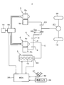
- the vehicle 1 is configured as a hybrid vehicle in which a plurality of power sources are combined.
- the vehicle 1 includes an internal combustion engine 3 and two motor generators 4 and 5 as a driving power source.
- the internal combustion engine 3 is configured as an in-line four-cylinder spark ignition type internal combustion engine including four cylinders 10.
- the internal combustion engine 3 burns between stoichiometric combustion that targets the stoichiometric air-fuel ratio or an air-fuel ratio in the vicinity thereof, and lean combustion that targets the air-fuel ratio set leaner than the target of the air-fuel ratio of stoichiometric combustion.
- the form can be switched.
- the internal combustion engine 3 and the first motor / generator 4 are connected to a power split mechanism 6.
- the first motor / generator 4 has a stator 4a and a rotor 4b.
- the first motor / generator 4 functions as a generator that generates power by receiving the power of the internal combustion engine 3 distributed by the power split mechanism 6 and also functions as an electric motor driven by AC power.
- the second motor / generator 5 includes a stator 5a and a rotor 5b, and functions as an electric motor and a generator, respectively.
- Each motor / generator 4, 5 is connected to a battery 16 via a motor control device 15.
- the motor control device 15 converts the electric power generated by each motor / generator 4, 5 into direct current and stores it in the battery 16, and converts the electric power of the battery 16 into alternating current and supplies it to each motor / generator 4, 5.
- the second motor / generator 5 corresponds to the motor / generator according to the present invention.
- the power split mechanism 6 is configured as a single pinion type planetary gear mechanism.
- the power split mechanism 6 is a planetary that holds a sun gear S as an external gear, a ring gear R as an internal gear arranged coaxially with the sun gear S, and a pinion P meshing with these gears S and R so as to be able to rotate and revolve.
- Carrier C The engine torque output from the internal combustion engine 3 is transmitted to the planetary carrier C of the power split mechanism 6.
- the rotor 4 b of the first motor / generator 4 is connected to the sun gear S of the power split mechanism 6. Torque output from the power split mechanism 6 via the ring gear R is transmitted to an output unit such as the output gear train 20.
- the output gear train 20 includes an output drive gear 21 that rotates integrally with the ring gear R of the power split mechanism 6, and an output driven gear 22 that meshes with the output drive gear 21.
- a second motor / generator 5 is connected to the output driven gear 22 via a gear 23.
- the gear 23 rotates integrally with the rotor 5 b of the second motor / generator 5.
- Torque output from the output driven gear 22 is distributed to the left and right drive wheels 18 via the differential device 27.
- the power transmission mechanism 6, the output gear train 22, and the differential device 27 include a gear group. Since each torque of the internal combustion engine 3 and the second motor / generator 5 is output from the drive wheel 18 via the power transmission mechanism 6, the output gear train 22 and the differential device 27, these devices are used in the power according to the present invention. Corresponds to the transmission mechanism.
- Control of each part of the vehicle 1 is controlled by an electronic control unit (ECU) 30.
- the ECU 30 performs various controls on the internal combustion engine 3 and the motor / generators 4 and 5.
- Various information on the vehicle 1 is input to the ECU 30.
- the rotational speed and torque of each motor / generator 4, 5 are input to the ECU 30 via the motor control device 15.
- the ECU 30 also outputs an output signal of an accelerator opening sensor 32 that outputs a signal corresponding to the amount of depression of the accelerator pedal 31, an output signal of a vehicle speed sensor 33 that outputs a signal corresponding to the vehicle speed of the vehicle 1, and the internal combustion engine 3.
- An output signal of the crank angle sensor 34 that outputs a signal corresponding to the engine speed (engine speed) is input.
- the ECU 30 refers to the output signal of the accelerator opening sensor 32 and the output signal of the vehicle speed sensor 33 to calculate the required drive torque requested by the driver, and performs various operations so that the system efficiency for the required drive torque is optimized.
- the vehicle 1 is controlled while switching modes. For example, in the low load region where the thermal efficiency of the internal combustion engine 3 decreases, the EV mode in which the combustion of the internal combustion engine 3 is stopped and the second motor / generator 5 is driven is selected. When the torque is insufficient with the internal combustion engine 3 alone, a hybrid mode is selected in which the second motor / generator 5 is used as a travel drive source together with the internal combustion engine 3.
- the ECU 30 moves the operating point of the internal combustion engine 3 so that the thermal efficiency of the internal combustion engine 3 is maintained as high as possible.
- the required drive torque for the vehicle 1 cannot be provided by the engine torque of the internal combustion engine 3 alone, the shortage of the required drive torque is compensated by the motor torque of the second motor / generator 5.
- the motor torque of the second motor / generator 5 becomes a small value near 0 Nm. In such a case, the pressing force between the gear 23 connected to the second motor / generator 5 and the output driven gear 22 is weakened.
- the ECU 30 performs noise suppression control that suppresses such noise generated in the power transmission mechanism.
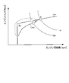
- a noise deterioration area Ar where noise exceeding a permissible limit is generated is defined by the engine speed and engine torque, and a noise suppression line Lnv that avoids the noise deterioration area Ar is set.
- the ECU 30 sets the operating point X of the internal combustion engine 3 to a dashed line so that the operating point X of the internal combustion engine 3 moving on the fuel efficiency line La set based on the thermal efficiency of the internal combustion engine 3 does not enter the noise deterioration region Ar. It restricts on the noise suppression line Lnv shown by.
- the noise deterioration area Ar and the noise suppression line Lnv are specified in advance by an actual machine test or the like, and their information is stored in the ECU 30. Since noise generation conditions vary depending on the combustion mode of the internal combustion engine 3, the noise deterioration region Ar and the noise suppression line Lnv are set for each combustion mode of the internal combustion engine 3.
- the fuel consumption line La is also set for each combustion mode. As shown in FIG. 3, the noise suppression line LnvL corresponding to lean combustion is set at a lower torque and higher rotation side than the noise suppression line LnvS corresponding to stoichiometric combustion. In the case of lean combustion, a noise deterioration region ArL indicated by hatching is located on the high torque low rotation side of the noise suppression line LnvL.
- a noise deterioration area ArS indicated by hatching is located on the high torque low rotation side from the noise suppression line LnvS.
- the noise deterioration region ArL of lean combustion is wider than the noise deterioration region ArS of stoichiometric combustion, and a part of the noise deterioration region ArL overlaps with the noise deterioration region ArS.
- the air-fuel ratio change control that is performed in order to switch the combustion mode of the internal combustion engine 3 is performed by the ECU 30 according to the required drive torque and other requirements. Switching from lean combustion to stoichiometric combustion is performed in a short time by temporarily increasing the amount of fuel supplied to the internal combustion engine 3 in consideration of the response delay of the air amount. Therefore, the engine torque temporarily increases as the fuel amount increases. As shown in FIG. 3, when the combustion mode of the internal combustion engine 3 is switched from lean combustion to stoichiometric combustion during execution of noise suppression control and the operating point is changed from point B to point A, the air-fuel ratio is changed at point B.
- the point moves to the point A after moving to the point C as indicated by the dashed arrow. Since the point C is in the noise deterioration area ArS of stoichiometric combustion, noise is generated.
- the air-fuel ratio is changed after changing from point B to point B 'on the low torque side. Even if the engine torque increases due to the change of the air-fuel ratio and reaches the point C ′, the starting point of the increase in the engine torque is the point B ′ on the lower torque side than the point B, so the point C ′ is within the noise deterioration region ArS. Entering is avoided. Therefore, the noise accompanying the change of the air-fuel ratio can be suppressed.
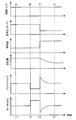
- the change with time of various parameters from the point B to the point A of the internal combustion engine 3 is as shown in the time chart of FIG.
- the operating point is at point B on the noise suppression line LnvL. If there is a request for switching from lean combustion to stoichiometric combustion at time t2, the ECU 30 reduces the engine torque. As a result, the operating point of the internal combustion engine 3 changes from point B to point B ′. As shown in FIG. 3, the point B ′ deviates to the lower torque side than the equal power line Lp.
- the motor torque is increased simultaneously with the decrease in engine torque.
- the ECU 30 executes air-fuel ratio change control. That is, the ECU 30 increases the amount of fuel supplied to the internal combustion engine 3 and decreases the amount of air. As a result, the engine torque temporarily increases and the operating point of the internal combustion engine 3 changes from the point B ′ to the point C ′. In order to offset the increase in the engine torque and maintain the driving torque, the motor torque is decreased at time t3.
- the change in the engine torque is absorbed by setting the motor torque to a negative value, that is, by generating power by the second motor / generator 5.
- the engine torque increased at time t3 is gradually reduced by decreasing the air amount. By adjusting the air amount, the operating point of the internal combustion engine 3 reaches point A on the equal power line Lp at time t4.
- the ECU 30 when switching from stoichiometric combustion to lean combustion during execution of noise suppression control, the ECU 30 does not change the operating point of the internal combustion engine 3 before execution of air-fuel ratio change control. Switching from stoichiometric combustion to lean combustion is performed in a short time by temporarily reducing the amount of fuel supplied to the internal combustion engine 3 in consideration of the response delay of the air amount. For this reason, the engine torque temporarily decreases as the fuel amount decreases. Therefore, the engine torque changes in a direction advantageous to noise. For example, as shown in FIG.
- step S1 the ECU 30 acquires vehicle information of the vehicle 1 with reference to the various sensors described above. Examples of vehicle information acquired by the ECU 30 include the accelerator opening of the vehicle 1, the vehicle speed, the engine speed of the internal combustion engine 3, and the speeds and torques of the motor generators 4 and 5.
- step S2 the ECU 30 calculates a required drive torque Tp based on the accelerator opening and the vehicle speed. The required drive torque Tp is calculated based on a preset map.
- step S3 the ECU 30 determines the combustion mode of the internal combustion engine 3 as either lean combustion or stoichiometric combustion based on the calculated required driving torque Tp and other vehicle information.
- the ECU 30 reads information on the fuel consumption line and the noise suppression line prepared in advance corresponding to the combustion mode.
- step S4 the ECU 30 obtains the intersection of the equal power line corresponding to the required drive torque Tp calculated in step S2 and the fuel consumption line or the noise suppression line, so that the operating point of the internal combustion engine 3 that is the control target, that is, the engine The rotational speed Ne and the engine torque Te are calculated.
- the intersection of the noise suppression line and the equal power line is calculated as the operating point of the internal combustion engine 3 as a control target, the operating point of the internal combustion engine 3 is limited on the noise suppression line. That is, noise suppression control is performed.
- step S5 the ECU 30 determines whether or not there is a request for switching the combustion mode.
- This switching request is mainly generated from the viewpoint of system efficiency.
- the ECU 30 calculates the system efficiency with respect to the required drive torque when maintaining the combustion mode and when switching the combustion mode, and generates a switching request when switching the combustion mode has higher system efficiency than maintaining the combustion mode. There may be a case where the switching request is generated by a factor other than the system efficiency. If there is a switching request for the combustion mode, the process proceeds to step S6, and if there is no switching request, the process proceeds to step S7.
- FIG. 7 shows the processing content of step S6.
- the ECU 30 determines whether noise suppression control is being executed. Whether or not the noise suppression control is being executed is based on whether or not the current operating point of the internal combustion engine 3 is limited to either the noise suppression line LnvL for lean combustion or the noise suppression line LnvS for stoichiometric combustion. Is determined. If the noise suppression control is being executed, the process proceeds to step S62. If the noise suppression control is not being executed, the process proceeds to step S64.
- step S62 the ECU 30 determines whether the combustion mode of the internal combustion engine 3 is lean combustion. This determination is performed based on the processing result of step S3 in FIG. When the combustion mode is lean combustion, the process proceeds to step S63. If the combustion mode is not lean combustion, that is, stoichiometric combustion, step S63 is skipped and the process proceeds to step S64.
- step S63 the ECU 30 changes the operating point of the internal combustion engine 3 so that the engine torque decreases. That is, as shown in FIG. 3, the ECU 30 changes the operating point of the internal combustion engine 3 to a lower torque side than the lean combustion noise suppression line LnvL.
- the amount of change is set according to the operating state of the internal combustion engine 3. Both the engine speed and the engine torque can be changed as long as the operating point of the internal combustion engine 3 does not change to the inner side of the noise suppression line LnvL, that is, the low rotation high torque side, as shown in FIG. Only the engine torque may be reduced while keeping the engine speed constant.
- step 63 as shown in FIG.
- the ECU 30 causes the motor torque of the second motor / generator 5 to synchronize with the decrease in engine torque. Increase.
- the operating point B is moved to the operating point B ′′ on the higher rotation and lower torque side than the noise suppression line LnvL along the equal power line Lp.
- the operating point can be changed to the lower torque side than the noise suppression line LnvL while maintaining the power of the internal combustion engine 3. Therefore, in the case of FIG. 8, since the power of the internal combustion engine 3 is maintained even when the engine torque is reduced, the above-described assistance due to the increase in the motor torque can be reduced or eliminated.
- step S64 the ECU 30 executes air-fuel ratio change control to switch the combustion mode.
- the ECU 30 increases the amount of fuel supplied to the internal combustion engine 3 and decreases the amount of air.
- the ECU 30 reduces the amount of fuel supplied to the internal combustion engine 3 and increases the amount of air.
- step S65 the ECU 30 calculates an engine torque Te ′ at the time of transition in which the engine torque changes in step S65. Then, the motor torque for suppressing the change in engine torque is calculated in steps S66 to S68.
- step S67 the ECU 30 calculates an upper limit value Tmmax and a lower limit value Tmmin of the motor torque.
- the upper limit value Tmmax and the lower limit value Tmmin correspond to input / output restrictions of the battery 16, respectively. That is, since the second motor / generator 5 cannot be driven beyond the output limit of the battery 16, the upper limit value Tmmax of the motor torque is calculated based on the output limit of the battery 16. In addition, since the second motor / generator 5 cannot generate power exceeding the input limit of the battery 16, the lower limit value Tmmin of the motor torque is calculated based on the input limit of the battery 16. The input / output limit of the battery 16 is set based on the rating.
- a motor torque guard process is performed in step S68. That is, the motor torque base value Tmb calculated in step S66 is compared with the upper limit value Tmmax and the lower limit value Tmmin, and the following processing is performed so that the motor torque Tm does not exceed these limit values.
- Tmb ⁇ Tmmin Tm ⁇ Tmmin
- Tm ⁇ Tmmax Tm ⁇ Tmmax
- step S69 the ECU 30 determines whether or not the motor torque Tm is limited by the upper limit value Tmmax or the lower limit value Tmmin. If the motor torque Tm is limited, that is, if the motor torque base value Tmb cannot be used as the motor torque Tm, the process proceeds to step S70.
- the motor torque Tm is limited, surplus energy is generated because not all of the engine torque change accompanying the air-fuel ratio change control of the internal combustion engine 3 can be absorbed by the control of the second motor / generator 5. Therefore, in step S70, the ECU 30 changes the ignition timing as an operation parameter of the internal combustion engine 3 to correct the engine torque.
- step S71 the ECU 30 controls the second motor / generator 5 to synchronize with the correction of the engine torque by instructing the motor control device 15 of the limited motor torque Tm. Then, the process returns to step S65, and the processes from step S65 to step S71 are repeated until the motor torque is not limited.
- the ECU 30 When the engine torque of the internal combustion engine 3 changes in the increasing direction as the combustion mode is switched, but the motor torque Tm is limited and all of the change cannot be absorbed by the power generation of the second motor / generator 5, the ECU 30 The ignition timing of the internal combustion engine 3 is changed so that the engine torque decreases. That is, the ECU 30 retards or advances the ignition timing in consideration of the current operating state of the internal combustion engine 3.
- the internal combustion engine 3 is a direct injection type internal combustion engine
- the engine torque can be reduced by changing the fuel injection timing as an operation parameter. By performing such engine torque reduction control, surplus energy is reduced, so that a shock associated with a change in the air-fuel ratio can be suppressed.
- the process proceeds to step S72, and the ECU 30 instructs the motor controller 15 to send the second motor by commanding the motor torque Tm.
- the ECU 30 determines whether or not a control end condition set as a condition for ending the control for absorbing the change in the engine torque accompanying the change in the air-fuel ratio by the power generation of the second motor / generator 5 is satisfied.
- the control termination condition is that the time change rate of the engine torque is less than a predetermined value.
- step S65 If the control end condition is not satisfied, the ECU 30 returns the process to step S65, and repeats the processes from step S65 to step S72 until the control end condition is satisfied.
- the ECU 30 shifts the operating point of the internal combustion engine 3 to the target operating point (Ne, Te) in step S74. Then, the process returns to step S6 in FIG. 6 to end the current control routine.
- step S7 the ECU 30 calculates the motor torque Tm in step S7. This process is the same as the process from step S65 to step S68 of FIG.
- step S8 the ECU 30 shifts the operating point of the internal combustion engine 3 to the target operating point (Ne, Te).
- step S ⁇ b> 9 the ECU 30 controls the second motor / generator 5 by instructing the motor control device 15 with the motor torque Tm so as to synchronize with the shift of the operating point of the internal combustion engine 3. Thereafter, the current control routine is terminated.
- the ECU 30 executes the control routine of FIGS. 6 and 7 described above, noise generated in the power transmission mechanism is suppressed when the combustion mode is switched during the execution of the noise suppression control.
- the ECU 30 executes the control routine of FIG. 7 as the combustion mode switching means according to the present invention by executing step S64 in FIG. 7 and the noise suppression control means according to the present invention by executing step S4 in FIG.
- step S65 to step S72 in FIG. 7 By executing the control from step S65 to step S72 in FIG. 7 as the transient control means according to the present invention by executing S63, executing step S71 in FIG. 7 as the motor control means according to the present invention.
- each functions as an engine control means according to the present invention.
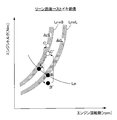
- an auxiliary line LnvA positioned on the low torque high rotation side than the above-described lean combustion noise suppression line LnvL is set, and the auxiliary line LnvA is used in the transient control described above. Since other matters are common to the first embodiment, description thereof is omitted.
- the auxiliary line LnvA is set in advance in consideration of the possibility that the operating point of the internal combustion engine 3 enters the noise deterioration region ArS of stoichiometric combustion due to an increase in engine torque accompanying the change of the air-fuel ratio.
- the auxiliary line LnvA is set in advance so that the engine torque does not enter the noise deterioration region ArS even if the engine torque increases on the auxiliary line LnvA due to the change in the combustion mode.
- the ECU 30 when switching the combustion mode of the internal combustion engine 3 from lean combustion to stoichiometric combustion during execution of noise suppression control and changing the operating point from point B to point A, the ECU 30 is indicated by an arrow.
- the air-fuel ratio is changed after the operating point of the internal combustion engine 3 is changed from the point B to the point B ′′ on the lower torque side of the noise suppression line LnvL, which is the intersection of the equal power line Lp and the auxiliary line LnvA.
- the operating point of the internal combustion engine 3 does not enter the noise deterioration area ArS of stoichiometric combustion as long as the increase in engine torque is set on the auxiliary line LnvA.
- the operating point of the internal combustion engine 3 is changed to the low torque side along the equal power line Lp as in the embodiment of FIG. 8, so that the power of the internal combustion engine 3 can be maintained. Therefore, assistance due to an increase in motor torque can be reduced or eliminated.
- the operating point of the internal combustion engine 3 is set along the equal power line LP as shown by the dashed arrow, rather than the noise suppression line LnvL. It is also possible to change to the X point on the low torque side and on the auxiliary line LnvA. Also in this case, since the operating point of the internal combustion engine 3 can be prevented from entering the noise deterioration area ArS of stoichiometric combustion by changing the air-fuel ratio, noise can be suppressed.
- the present invention is not limited to the above embodiments, and can be implemented in various forms within the scope of the gist of the present invention.
- Each of the above embodiments is an application of the present invention to a hybrid vehicle having two motors / generators, in which one motor / generator and an internal combustion engine are connected to a power split mechanism. Is not limited to this type of hybrid vehicle.
- the present invention can also be applied to a hybrid vehicle in which the motor torque of one motor / generator is transmitted to an output unit that outputs engine torque of an internal combustion engine.
Landscapes
- Engineering & Computer Science (AREA)
- Chemical & Material Sciences (AREA)
- Combustion & Propulsion (AREA)
- Mechanical Engineering (AREA)
- Transportation (AREA)
- General Engineering & Computer Science (AREA)
- Automation & Control Theory (AREA)
- Theoretical Computer Science (AREA)
- Signal Processing (AREA)
- Electric Propulsion And Braking For Vehicles (AREA)
- Control Of Vehicle Engines Or Engines For Specific Uses (AREA)
- Hybrid Electric Vehicles (AREA)
- Combined Controls Of Internal Combustion Engines (AREA)
- Electrical Control Of Air Or Fuel Supplied To Internal-Combustion Engine (AREA)
Abstract
Priority Applications (5)
| Application Number | Priority Date | Filing Date | Title |
|---|---|---|---|
| DE112013006494.4T DE112013006494B4 (de) | 2013-01-24 | 2013-01-24 | Steuervorrichtung für ein Hybridfahrzeug |
| US14/759,013 US9604528B2 (en) | 2013-01-24 | 2013-01-24 | Control apparatus for hybrid vehicle |
| PCT/JP2013/051467 WO2014115285A1 (fr) | 2013-01-24 | 2013-01-24 | Régulateur de véhicule hybride |
| CN201380069449.7A CN104918834B (zh) | 2013-01-24 | 2013-01-24 | 混合动力车辆的控制装置 |
| JP2014558369A JP5943097B2 (ja) | 2013-01-24 | 2013-01-24 | ハイブリッド車両の制御装置 |
Applications Claiming Priority (1)
| Application Number | Priority Date | Filing Date | Title |
|---|---|---|---|
| PCT/JP2013/051467 WO2014115285A1 (fr) | 2013-01-24 | 2013-01-24 | Régulateur de véhicule hybride |
Publications (1)
| Publication Number | Publication Date |
|---|---|
| WO2014115285A1 true WO2014115285A1 (fr) | 2014-07-31 |
Family
ID=51227100
Family Applications (1)
| Application Number | Title | Priority Date | Filing Date |
|---|---|---|---|
| PCT/JP2013/051467 Ceased WO2014115285A1 (fr) | 2013-01-24 | 2013-01-24 | Régulateur de véhicule hybride |
Country Status (5)
| Country | Link |
|---|---|
| US (1) | US9604528B2 (fr) |
| JP (1) | JP5943097B2 (fr) |
| CN (1) | CN104918834B (fr) |
| DE (1) | DE112013006494B4 (fr) |
| WO (1) | WO2014115285A1 (fr) |
Cited By (2)
| Publication number | Priority date | Publication date | Assignee | Title |
|---|---|---|---|---|
| JP5943097B2 (ja) * | 2013-01-24 | 2016-06-29 | トヨタ自動車株式会社 | ハイブリッド車両の制御装置 |
| CN107407216A (zh) * | 2014-11-06 | 2017-11-28 | 沃尔布罗有限责任公司 | 发动机控制策略 |
Families Citing this family (14)
| Publication number | Priority date | Publication date | Assignee | Title |
|---|---|---|---|---|
| WO2014118950A1 (fr) | 2013-01-31 | 2014-08-07 | トヨタ自動車株式会社 | Dispositif de commande pour véhicule hybride |
| JP5915606B2 (ja) * | 2013-09-06 | 2016-05-11 | トヨタ自動車株式会社 | ハイブリッド車両の制御装置 |
| JP5861745B2 (ja) * | 2014-06-30 | 2016-02-16 | トヨタ自動車株式会社 | 内燃機関の制御装置 |
| DE102015007913A1 (de) * | 2015-06-20 | 2016-12-22 | Man Truck & Bus Ag | Verfahren zur Online-Adaption einer Kennlinie eines Hybridfahrzeugs |
| US9440640B1 (en) * | 2015-10-16 | 2016-09-13 | Borgwarner Inc. | Gear change torque fill strategy |
| US10337613B2 (en) * | 2016-12-21 | 2019-07-02 | Fca Us Llc | Transmission shift torque management with fuel enleanment |
| US10364765B2 (en) | 2017-02-15 | 2019-07-30 | GM Global Technology Operations LLC | Method to select optimal mode on a multi-mode engine with charging |
| DE102017206519B3 (de) * | 2017-04-18 | 2018-03-29 | Audi Ag | Verfahren zum Begrenzen eines Störgeräuschs einer Verbrennungskraftmaschine, Vorrichtung für ein Kraftfahrzeug und Kraftfahrzeug |
| CN111479740B (zh) * | 2017-12-15 | 2023-02-28 | 日产自动车株式会社 | 电动装置控制方法和电动装置 |
| JP7027937B2 (ja) * | 2018-02-16 | 2022-03-02 | トヨタ自動車株式会社 | ハイブリッド車両の制御装置 |
| JP6596111B2 (ja) * | 2018-02-16 | 2019-10-23 | 本田技研工業株式会社 | 制御装置 |
| JP7198118B2 (ja) * | 2019-03-04 | 2022-12-28 | 日立Astemo株式会社 | ハイブリッド車用制御装置 |
| CN110667560A (zh) * | 2019-09-26 | 2020-01-10 | 浙江吉利新能源商用车集团有限公司 | 一种车辆降噪方法、装置及车辆 |
| US11754014B2 (en) * | 2021-05-25 | 2023-09-12 | Fang Shui | Apparatus and method for controlling transitions in a multi-combustion mode internal-combustion engine within a hybrid-electric vehicle |
Citations (7)
| Publication number | Priority date | Publication date | Assignee | Title |
|---|---|---|---|---|
| JPH1193725A (ja) * | 1997-09-17 | 1999-04-06 | Toyota Motor Corp | ギヤ機構における歯打ち音の低減方法、動力出力装置およびこの動力出力装置を搭載したハイブリッド車輌 |
| JP2000008904A (ja) * | 1998-06-19 | 2000-01-11 | Honda Motor Co Ltd | ハイブリッド駆動車両の制御装置 |
| JP2005127185A (ja) * | 2003-10-22 | 2005-05-19 | Toyota Motor Corp | 動力出力装置およびその制御方法並びに自動車 |
| JP2005163667A (ja) * | 2003-12-03 | 2005-06-23 | Toyota Motor Corp | ハイブリッド車両における内燃機関の制御方法 |
| JP2009255618A (ja) * | 2008-04-11 | 2009-11-05 | Toyota Motor Corp | 車両用駆動装置の制御装置 |
| JP2010095197A (ja) * | 2008-10-17 | 2010-04-30 | Toyota Motor Corp | 車両用動力伝達装置の制御装置 |
| JP2012193657A (ja) * | 2011-03-16 | 2012-10-11 | Toyota Motor Corp | 内燃機関の制御装置 |
Family Cites Families (11)
| Publication number | Priority date | Publication date | Assignee | Title |
|---|---|---|---|---|
| JP3534271B2 (ja) * | 1995-04-20 | 2004-06-07 | 株式会社エクォス・リサーチ | ハイブリッド車両 |
| JP2006274904A (ja) * | 2005-03-29 | 2006-10-12 | Mitsubishi Fuso Truck & Bus Corp | 内燃機関の制御装置 |
| JP4888154B2 (ja) | 2007-02-22 | 2012-02-29 | トヨタ自動車株式会社 | 車両およびその制御方法 |
| JP4150055B1 (ja) * | 2007-04-05 | 2008-09-17 | 北海道旅客鉄道株式会社 | 軌道車両用駆動システム及びそれを用いた軌道車両 |
| US7918763B2 (en) | 2007-04-12 | 2011-04-05 | Ford Global Technologies, Llc | Control strategy for multi-mode vehicle propulsion system |
| US7935025B1 (en) * | 2010-02-25 | 2011-05-03 | Ford Global Technologies, Llc | Methods and systems for assisted direct start control |
| US8712652B2 (en) | 2010-11-30 | 2014-04-29 | Toyota Jidosha Kabushiki Kaisha | Control device of hybrid vehicle |
| CN103313887B (zh) * | 2011-01-21 | 2016-03-23 | 丰田自动车株式会社 | 车辆控制装置 |
| GB2487433A (en) * | 2011-01-24 | 2012-07-25 | Gm Global Tech Operations Inc | An engine control method which alters a fuel request value |
| JP5664621B2 (ja) * | 2012-09-25 | 2015-02-04 | トヨタ自動車株式会社 | ハイブリッド車 |
| JP5943097B2 (ja) * | 2013-01-24 | 2016-06-29 | トヨタ自動車株式会社 | ハイブリッド車両の制御装置 |
-
2013
- 2013-01-24 JP JP2014558369A patent/JP5943097B2/ja not_active Expired - Fee Related
- 2013-01-24 WO PCT/JP2013/051467 patent/WO2014115285A1/fr not_active Ceased
- 2013-01-24 US US14/759,013 patent/US9604528B2/en not_active Expired - Fee Related
- 2013-01-24 DE DE112013006494.4T patent/DE112013006494B4/de not_active Expired - Fee Related
- 2013-01-24 CN CN201380069449.7A patent/CN104918834B/zh not_active Expired - Fee Related
Patent Citations (7)
| Publication number | Priority date | Publication date | Assignee | Title |
|---|---|---|---|---|
| JPH1193725A (ja) * | 1997-09-17 | 1999-04-06 | Toyota Motor Corp | ギヤ機構における歯打ち音の低減方法、動力出力装置およびこの動力出力装置を搭載したハイブリッド車輌 |
| JP2000008904A (ja) * | 1998-06-19 | 2000-01-11 | Honda Motor Co Ltd | ハイブリッド駆動車両の制御装置 |
| JP2005127185A (ja) * | 2003-10-22 | 2005-05-19 | Toyota Motor Corp | 動力出力装置およびその制御方法並びに自動車 |
| JP2005163667A (ja) * | 2003-12-03 | 2005-06-23 | Toyota Motor Corp | ハイブリッド車両における内燃機関の制御方法 |
| JP2009255618A (ja) * | 2008-04-11 | 2009-11-05 | Toyota Motor Corp | 車両用駆動装置の制御装置 |
| JP2010095197A (ja) * | 2008-10-17 | 2010-04-30 | Toyota Motor Corp | 車両用動力伝達装置の制御装置 |
| JP2012193657A (ja) * | 2011-03-16 | 2012-10-11 | Toyota Motor Corp | 内燃機関の制御装置 |
Cited By (3)
| Publication number | Priority date | Publication date | Assignee | Title |
|---|---|---|---|---|
| JP5943097B2 (ja) * | 2013-01-24 | 2016-06-29 | トヨタ自動車株式会社 | ハイブリッド車両の制御装置 |
| CN107407216A (zh) * | 2014-11-06 | 2017-11-28 | 沃尔布罗有限责任公司 | 发动机控制策略 |
| CN107407216B (zh) * | 2014-11-06 | 2021-07-30 | 沃尔布罗有限责任公司 | 发动机控制策略 |
Also Published As
| Publication number | Publication date |
|---|---|
| JP5943097B2 (ja) | 2016-06-29 |
| US20150353074A1 (en) | 2015-12-10 |
| DE112013006494T5 (de) | 2015-11-05 |
| CN104918834B (zh) | 2017-07-07 |
| DE112013006494B4 (de) | 2018-12-20 |
| US9604528B2 (en) | 2017-03-28 |
| CN104918834A (zh) | 2015-09-16 |
| JPWO2014115285A1 (ja) | 2017-01-26 |
Similar Documents
| Publication | Publication Date | Title |
|---|---|---|
| JP5943097B2 (ja) | ハイブリッド車両の制御装置 | |
| JP5842937B2 (ja) | ハイブリッド車の変速制御装置および変速制御方法 | |
| JP5861745B2 (ja) | 内燃機関の制御装置 | |
| JP5983873B2 (ja) | ハイブリッド車両の制御装置 | |
| JP6317263B2 (ja) | ハイブリッド車両の制御装置 | |
| JP7388213B2 (ja) | ハイブリッド車両の制御装置 | |
| US9764730B2 (en) | Vehicle control apparatus | |
| JP5950036B2 (ja) | ハイブリッド車両用駆動装置 | |
| WO2013108385A1 (fr) | Dispositif de commande de démarrage de moteur à combustion interne pour véhicule hybride | |
| CN104071156B (zh) | 用于混合动力车辆的控制设备 | |
| US8801568B2 (en) | Control apparatus and control method for hybrid vehicle | |
| JP2017193275A (ja) | ハイブリッド車両の制御装置 | |
| JP2017178227A (ja) | ハイブリッド車両の制御装置 | |
| JP2016203806A (ja) | ハイブリッド車両の制御装置 | |
| JP2014151668A (ja) | ハイブリッド車両の制御装置 | |
| JP2016112975A (ja) | ハイブリッド車両の出力制御装置 | |
| JP2015231797A (ja) | 動力伝達装置 | |
| JPWO2013108385A1 (ja) | ハイブリッド車両の内燃機関始動制御装置 |
Legal Events
| Date | Code | Title | Description |
|---|---|---|---|
| 121 | Ep: the epo has been informed by wipo that ep was designated in this application |
Ref document number: 13872703 Country of ref document: EP Kind code of ref document: A1 |
|
| WWE | Wipo information: entry into national phase |
Ref document number: 14759013 Country of ref document: US |
|
| ENP | Entry into the national phase |
Ref document number: 2014558369 Country of ref document: JP Kind code of ref document: A |
|
| WWE | Wipo information: entry into national phase |
Ref document number: 112013006494 Country of ref document: DE Ref document number: 1120130064944 Country of ref document: DE |
|
| 122 | Ep: pct application non-entry in european phase |
Ref document number: 13872703 Country of ref document: EP Kind code of ref document: A1 |