WO2014115315A1 - 距離測定システム、距離測定方法 - Google Patents
距離測定システム、距離測定方法 Download PDFInfo
- Publication number
- WO2014115315A1 WO2014115315A1 PCT/JP2013/051647 JP2013051647W WO2014115315A1 WO 2014115315 A1 WO2014115315 A1 WO 2014115315A1 JP 2013051647 W JP2013051647 W JP 2013051647W WO 2014115315 A1 WO2014115315 A1 WO 2014115315A1
- Authority
- WO
- WIPO (PCT)
- Prior art keywords
- distance
- pipe
- distance measurement
- pipes
- measurement system
- Prior art date
- Legal status (The legal status is an assumption and is not a legal conclusion. Google has not performed a legal analysis and makes no representation as to the accuracy of the status listed.)
- Ceased
Links
Images



Classifications
-
- G—PHYSICS
- G01—MEASURING; TESTING
- G01B—MEASURING LENGTH, THICKNESS OR SIMILAR LINEAR DIMENSIONS; MEASURING ANGLES; MEASURING AREAS; MEASURING IRREGULARITIES OF SURFACES OR CONTOURS
- G01B11/00—Measuring arrangements characterised by the use of optical techniques
- G01B11/14—Measuring arrangements characterised by the use of optical techniques for measuring distance or clearance between spaced objects or spaced apertures
-
- G—PHYSICS
- G01—MEASURING; TESTING
- G01B—MEASURING LENGTH, THICKNESS OR SIMILAR LINEAR DIMENSIONS; MEASURING ANGLES; MEASURING AREAS; MEASURING IRREGULARITIES OF SURFACES OR CONTOURS
- G01B11/00—Measuring arrangements characterised by the use of optical techniques
- G01B11/02—Measuring arrangements characterised by the use of optical techniques for measuring length, width or thickness
- G01B11/026—Measuring arrangements characterised by the use of optical techniques for measuring length, width or thickness by measuring distance between sensor and object
-
- G—PHYSICS
- G01—MEASURING; TESTING
- G01B—MEASURING LENGTH, THICKNESS OR SIMILAR LINEAR DIMENSIONS; MEASURING ANGLES; MEASURING AREAS; MEASURING IRREGULARITIES OF SURFACES OR CONTOURS
- G01B11/00—Measuring arrangements characterised by the use of optical techniques
- G01B11/16—Measuring arrangements characterised by the use of optical techniques for measuring the deformation in a solid, e.g. optical strain gauge
-
- G—PHYSICS
- G01—MEASURING; TESTING
- G01C—MEASURING DISTANCES, LEVELS OR BEARINGS; SURVEYING; NAVIGATION; GYROSCOPIC INSTRUMENTS; PHOTOGRAMMETRY OR VIDEOGRAMMETRY
- G01C3/00—Measuring distances in line of sight; Optical rangefinders
-
- G—PHYSICS
- G01—MEASURING; TESTING
- G01N—INVESTIGATING OR ANALYSING MATERIALS BY DETERMINING THEIR CHEMICAL OR PHYSICAL PROPERTIES
- G01N17/00—Investigating resistance of materials to the weather, to corrosion, or to light
- G01N17/006—Investigating resistance of materials to the weather, to corrosion, or to light of metals
-
- G—PHYSICS
- G01—MEASURING; TESTING
- G01N—INVESTIGATING OR ANALYSING MATERIALS BY DETERMINING THEIR CHEMICAL OR PHYSICAL PROPERTIES
- G01N21/00—Investigating or analysing materials by the use of optical means, i.e. using sub-millimetre waves, infrared, visible or ultraviolet light
- G01N21/84—Systems specially adapted for particular applications
- G01N21/88—Investigating the presence of flaws or contamination
-
- G—PHYSICS
- G01—MEASURING; TESTING
- G01S—RADIO DIRECTION-FINDING; RADIO NAVIGATION; DETERMINING DISTANCE OR VELOCITY BY USE OF RADIO WAVES; LOCATING OR PRESENCE-DETECTING BY USE OF THE REFLECTION OR RERADIATION OF RADIO WAVES; ANALOGOUS ARRANGEMENTS USING OTHER WAVES
- G01S17/00—Systems using the reflection or reradiation of electromagnetic waves other than radio waves, e.g. lidar systems
- G01S17/02—Systems using the reflection of electromagnetic waves other than radio waves
- G01S17/06—Systems determining position data of a target
- G01S17/08—Systems determining position data of a target for measuring distance only
-
- G—PHYSICS
- G01—MEASURING; TESTING
- G01S—RADIO DIRECTION-FINDING; RADIO NAVIGATION; DETERMINING DISTANCE OR VELOCITY BY USE OF RADIO WAVES; LOCATING OR PRESENCE-DETECTING BY USE OF THE REFLECTION OR RERADIATION OF RADIO WAVES; ANALOGOUS ARRANGEMENTS USING OTHER WAVES
- G01S17/00—Systems using the reflection or reradiation of electromagnetic waves other than radio waves, e.g. lidar systems
- G01S17/88—Lidar systems specially adapted for specific applications
-
- G—PHYSICS
- G01—MEASURING; TESTING
- G01B—MEASURING LENGTH, THICKNESS OR SIMILAR LINEAR DIMENSIONS; MEASURING ANGLES; MEASURING AREAS; MEASURING IRREGULARITIES OF SURFACES OR CONTOURS
- G01B7/00—Measuring arrangements characterised by the use of electric or magnetic techniques
- G01B7/02—Measuring arrangements characterised by the use of electric or magnetic techniques for measuring length, width or thickness
- G01B7/023—Measuring arrangements characterised by the use of electric or magnetic techniques for measuring length, width or thickness for measuring distance between sensor and object
-
- G—PHYSICS
- G01—MEASURING; TESTING
- G01B—MEASURING LENGTH, THICKNESS OR SIMILAR LINEAR DIMENSIONS; MEASURING ANGLES; MEASURING AREAS; MEASURING IRREGULARITIES OF SURFACES OR CONTOURS
- G01B7/00—Measuring arrangements characterised by the use of electric or magnetic techniques
- G01B7/14—Measuring arrangements characterised by the use of electric or magnetic techniques for measuring distance or clearance between spaced objects or spaced apertures
Definitions
- the present invention relates to a distance measurement system and a distance measurement method.
- a crack such as creep damage may occur in a welded portion (longitudinal weld line) of a large-diameter pipe used for a boiler or the like (for example, see Patent Document 1).
- the strain generated in the pipes and welds is measured, and the signs of cracks in the pipes, as well as the repair and replacement times (lifetime) of the pipes and welds are determined. .
- This invention is made in view of the said subject, and provides the distance measurement system which can grasp
- a distance measuring system is provided on a surface of a metal first pipe, and a reference member serving as a reference for distance measurement, and a welded portion on the first pipe
- An attachment member installed on the surface of the metal second pipe connected via the distance sensor, a distance sensor attached to the attachment member for measuring a distance to the reference member, and an output from the distance sensor
- a measurement unit that measures the distance based on the distance.
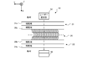
- FIG. 1 is a diagram showing an outline of a distance measurement system 10.
- FIG. 1 is a diagram for explaining details of a distance measurement system 10.
- FIG. It is a top view for demonstrating the positional relationship of the reflecting plate 50 and the laser displacement meter 52.
- FIG. It is a figure for demonstrating attachment or detachment of the laser displacement meter.
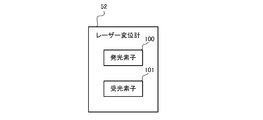
- It is a figure which shows an example of a structure of the laser displacement meter.
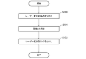
- It is a flowchart which shows an example of the process which an operator performs when the distance L is measured.
- FIG. 1 is a diagram showing an outline of a distance measurement system 10 according to an embodiment of the present invention provided in the pipes 15 and 16, and FIG. 2 is a diagram for explaining the details of the distance measurement system 10. is there.
- FIG. 3 is a plan view for explaining the positional relationship between the reflector 50 and the laser displacement meter 52 in the distance measuring system 10.
- the area where the distance measurement system 10 is installed is enlarged.
- the XY plane is a horizontal plane
- the + Z-axis direction indicates the upper side in the vertical direction.
- the pipes 15 and 16 are stainless steel (metal) large-diameter pipes used for boilers, and the opening at one end of the pipe 15 and the opening at one end of the pipe 16 are welded (longitudinal welding). .
- the other ends of the pipes 15 and 16 are connected to various types of boiler equipment and other pipes, but are omitted here for convenience.
- the heat-affected zone 21 includes a coarse grain region 30a and a fine grain region 31a composed of crystal grains finer than the crystal grains constituting the coarse grain region 30a.
- the coarse grain region 30a is generated on the welded portion 20 side where the pipes 15 and 16 are welded.
- the heat affected zone 22 is composed of a coarse grain region 30b generated on the welded portion 20 side and a fine grain zone 31b.
- the heat affected parts 21 and 22 are generated in the regions on both sides of the welded part 20.
- the welded part 20 and the heat affected parts 21 and 22 are distorted and creep damaged.
- the welded portion 20 and the heat-affected portions 21 and 22 extend in the longitudinal direction of the pipes 15 and 16.
- the elongation generated in the welded portion 20 and the heat-affected portions 21 and 22 is maintained even when the piping 15 is cooled, that is, when the boiler is stopped and the piping 15 is at approximately room temperature.
- the distance measurement system 10 is a system for grasping a change (elongation) in the distance between the welded part 20 and the heat affected parts 21 and 22, and includes a reflector 50, an attachment member 51, a laser displacement meter 52, and a processing device 53. Consists of including.
- the reflector 50 (reference member) is an L-shaped member used as a reference for distance measurement.
- the reflecting plate 50 is formed with a bottom surface that is welded to a surface that is substantially water-side in the pipe 16 (first pipe), and a reflecting surface that is bent so as to be perpendicular to the bottom surface.
- the reflector 50 is made of an alloy (for example, Inconel (registered trademark) alloy), platinum, or the like that has excellent heat resistance and is not easily oxidized or deformed.
- the temperature at which the oxidation of the material forming the reflector 50 proceeds sufficiently higher than the maximum value of the temperatures of the pipes 15 and 16 (for example, 450 ° C. at which the creep phenomenon occurs).
- the material of the reflecting plate 50 is selected.
- the attachment member 51 is a member to which the laser displacement meter 52 is attached, and includes, for example, three cylindrical pins 60 to 62 as shown in FIG.
- the pins 60 to 62 are pins for determining the mounting position of the laser displacement meter 52 with high accuracy, and the bottom surfaces of the pins 60 to 62 are welded to a surface that is substantially waterside in the pipe 15 (second pipe). Further, the pins 60 to 62 are welded at positions where the laser displacement meter 52 and the reflection surface of the reflection plate 50 face each other when the laser displacement meter 52 is attached.
- the pins 60 to 62 and the reflecting plate 50 are connected to the pipes 15 and 16 with the welded portion 20 and the heat affected portions 21 and 22 interposed therebetween so that the change (elongation) of the distance between the welded portion 20 and the heat affected portions 21 and 22 can be measured.
- the attachment member 51 is also made of an alloy (for example, Inconel (registered trademark) alloy), platinum, or the like that is excellent in heat resistance and hardly oxidizes or deforms, like the reflector 50.
- the temperature at which the oxidation of the material forming the attachment member 51 proceeds is sufficiently higher than the maximum value of the temperatures of the pipes 15 and 16 (for example, 450 ° C. at which the creep phenomenon occurs).
- the material of the attachment member 51 is selected.
- the laser displacement meter 52 is a laser-type (optical) distance sensor that can be attached to and detached from the attachment member 51. On the bottom surface of the laser displacement meter 52, each of the mounting holes 65 to 62 into which the pins 60 to 62 are inserted. 67 is formed. Further, the laser displacement meter 52 includes a light emitting element 100 and a light receiving element 101 as shown in FIG.
- the light emitting element 100 is a semiconductor laser that outputs a laser beam that irradiates the reflecting surface of the reflecting plate 50.
- the light receiving element 101 receives the laser beam reflected by the reflecting plate 50 and outputs a signal corresponding to the distance L from the laser displacement meter 52 to the surface of the reflecting surface of the reflecting plate 50. Since the laser displacement meter 52 uses a semiconductor laser, the distance L can be measured only when the ambient temperature is within a predetermined temperature range T (for example, ⁇ 10 ° C. to 45 ° C.).
- the processing device 53 is a device that executes various processes based on the output from the laser displacement meter 52, and includes a measurement unit 70, a calculation unit 71, an alarm output unit 72, and a monitor 73. Note that the measurement unit 70, the calculation unit 71, and the alarm output unit 72 are functional blocks realized by a microcomputer (not shown) included in the processing device 53.
- the calculation unit 71 is based on the information indicating the relationship between the remaining life of the pipes 15 and 16 and the welded portion 20 and the distance L, which is stored in advance in a memory (not shown) of the processing device 53, and the measured distance L.
- the remaining life of the pipe 15 and the like is calculated. Note that the relationship between the remaining life of the pipe 15 and the like and the distance L is experimentally obtained in advance.
- the alarm output unit 72 displays an alarm on the monitor 73 when the calculated remaining life of the pipe 15 or the like becomes shorter than a predetermined value. Therefore, the operator can immediately grasp that a crack has occurred in the pipe 15 and the like and the remaining life is shortened.
- the laser displacement meter 52 can measure the distance L only when it is in the predetermined temperature range T. For this reason, the laser displacement meter 52 is removed when the boiler is operating (when the temperature of the pipe 15 becomes very high). And an operator measures the distance L in the case of the periodic inspection which the boiler has stopped, for example. The regular inspection is performed every year, for example.
- the operator attaches the laser displacement meter 52 to the mounting member 51 during the periodic inspection, that is, when the temperature of the pipe 15 or the like is almost normal temperature (for example, 25 ° C.) and falls within the predetermined temperature range T ( S100). Then, the operator operates the laser displacement meter 52 and measures the distance L (S101). When the remaining life of the pipe 15 and the like is calculated in addition to the distance L, the operator removes the laser displacement meter 52 (S102). Since such processing is repeated for each periodic inspection, the operator can accurately grasp the distance L (strain) indicating an indication of the occurrence of a crack occurring in the pipe 15 or the like for each periodic inspection.
- the distance L strain
- the distance measurement system 10 that is one embodiment of the present invention has been described above.
- the operator can grasp the change in the distance L by using the distance measurement system 10. Further, the distance L changes according to the state of a crack generated in the welded portion 20. Therefore, the operator can accurately grasp the sign of the occurrence of a crack in the pipe 15 and the welded part 20 based on the change in the distance L. Moreover, since it is possible to determine the exact time of repair and replacement of the piping 15 based on these pieces of information, useless repairs can be reduced and maintenance costs can be reduced.
- the reflecting plate 50 is welded to the pipe 16, but the present invention is not limited to this.
- a member similar to the attachment member 51 may be provided on the surface of the pipe 16 and the reflection plate 50 may be appropriately attached.
- the reflecting plate 50 is welded to the pipe 16, an error in attaching the reflecting plate 50 can be eliminated, and therefore the distance L can be measured with higher accuracy.
- the material of the reflector 50 is selected so that the temperature at which the oxidation of the material forming the reflector 50 proceeds sufficiently higher than the maximum temperature of the pipes 15 and 16. For this reason, it can prevent that the reflecting plate 50 is oxidized and the measurement precision of the distance L deteriorates.
- the material of the mounting member 51 is selected so that the temperature at which the material forming the mounting member 51 progresses is sufficiently higher than the maximum temperature of the pipes 15 and 16. For this reason, it can prevent that the attachment member 51 is oxidized and the measurement precision of the distance L deteriorates.
- the distance L can be measured with high accuracy by using the laser displacement meter 52.
- the distance measurement system 10 measured the distance L of the area
- the operator can attach / detach the laser displacement meter 52 to / from the pins 60 to 62 at an appropriate timing.
- the laser displacement meter 52 is attached to the pipe 16 at the regular inspection, and the distance L is measured. Therefore, the laser displacement meter 52 can measure the distance L with high accuracy.
- the regions of the fine grain regions 31a and 31b are particularly elongated. Since the reflecting plate 50 and the attachment member 51 are provided with the welded portion 20 and the heat affected portions 21 and 22 sandwiched therebetween, it is possible to accurately grasp the influence of the crack.
- Example 2 is for making an understanding of this invention easy, and is not for limiting and interpreting this invention.
- the present invention can be changed and improved without departing from the gist thereof, and the present invention includes equivalents thereof.
Landscapes
- Physics & Mathematics (AREA)
- General Physics & Mathematics (AREA)
- Engineering & Computer Science (AREA)
- Electromagnetism (AREA)
- Life Sciences & Earth Sciences (AREA)
- Radar, Positioning & Navigation (AREA)
- Remote Sensing (AREA)
- Biochemistry (AREA)
- Health & Medical Sciences (AREA)
- Chemical & Material Sciences (AREA)
- Analytical Chemistry (AREA)
- Computer Networks & Wireless Communication (AREA)
- General Health & Medical Sciences (AREA)
- Immunology (AREA)
- Pathology (AREA)
- Biodiversity & Conservation Biology (AREA)
- Ecology (AREA)
- Environmental & Geological Engineering (AREA)
- Environmental Sciences (AREA)
- Length Measuring Devices By Optical Means (AREA)
Abstract
Description
距離測定システム10は、溶接部20および熱影響部21,22の距離の変化(伸び)を把握するためのシステムであり、反射板50、取り付け部材51、レーザー変位計52、および処理装置53を含んで構成される。
ここで、距離測定システム10を用いて距離Lが測定される際に作業者が実行する処理を、図6を参照しつつ説明する。前述のように、レーザー変位計52は所定の温度範囲Tにある場合のみ距離Lを測定することができる。このため、レーザー変位計52は、ボイラが動作している動作時(配管15の温度が非常に高くなる際)には取り外されている。そして、作業者は、例えば、ボイラが停止している定期点検の際に距離Lを測定する。なお、定期点検は例えば1年毎に実行される。
15,16 配管
20 溶接部
21,22 熱影響部
30a,30b 細粒域
31a,31b 粗粒域
50 反射板
51 取り付け部材
52 レーザー変位計
53 処理装置
60~62 ピン
65~67 取り付け穴
70 測定部
71 算出部
72 警報出力部
73 モニタ
100 発光素子
101 受光素子
Claims (11)
- 金属製の第1配管の表面に設置され、距離測定の基準となる基準部材と、
前記第1配管に溶接部を介して接続された金属製の第2配管の表面に設置される取り付け部材と、
前記取り付け部材に取り付けられる、前記基準部材までの距離を測定するための距離センサと、
前記距離センサからの出力に基づいて前記距離を測定する測定部と、
を備えることを特徴とする距離測定システム。 - 請求項1に記載の距離測定システムであって、
前記基準部材は、前記第1配管の表面に溶接されていること、
を特徴とする距離測定システム。 - 請求項2に記載の距離測定システムであって、
前記基準部材は、
前記第1及び第2配管が加熱された際の前記第1及び第2配管の温度の最大値より高い温度であっても酸化が進行しない材料で形成されること、
を特徴とする距離測定システム。 - 請求項1に記載の距離測定システムであって、
前記取り付け部材は、
前記第1及び第2配管が加熱された際の前記第1及び第2配管の温度の最大値より高い温度であっても酸化が進行しない材料で形成されること、
を特徴とする距離測定システム。 - 請求項1~4の何れか一項に記載の距離測定システムであって、
前記基準部材は、レーザー光を反射する反射板であり、
前記距離センサは、前記レーザー光を前記反射板に照射し、前記反射板から反射された前記レーザー光に基づいて前記距離を示す信号を出力すること、
を特徴とする距離測定システム。 - 請求項1~5の何れか一項に記載の距離測定システムであって、
前記溶接部は、
前記第1配管の一端の開口部と、前記第2配管の一端の開口部とを溶接すること、
を特徴とする距離測定システム。 - 請求項1~6の何れか一項に記載の距離測定システムであって、
前記距離センサは、
前記取り付け部材に対して着脱可能であること、
を特徴とする距離測定システム。 - 請求項7に記載の距離測定システムであって、
前記距離センサは、
前記第2配管の温度が、前記距離センサが前記基準部材までの距離を測定可能な所定の温度範囲内にある場合に前記取り付け部材に取り付けられること、
を特徴とする距離測定システム。 - 請求項1~8の何れか一項に記載の距離測定システムであって、
前記基準部材及び前記取り付け部材は、
前記第1及び第2配管が溶接された際に前記溶接部の両側に生成される熱影響部と、前記溶接部と、を挟んで前記第1及び第2配管のそれぞれの表面に設けられること、
を特徴とする距離測定システム。 - 金属製の第1配管の表面に設置され距離測定の基準となる基準部材と、前記第1配管に溶接部を介して接続された金属製の第2配管の表面に設置される取り付け部材と、を用いる距離測定方法であって、
前記取り付け部材に、前記基準部材までの距離を測定するための距離センサを取り付けるステップと、
前記距離センサを用いて前記距離を測定するステップと、
を含むことを特徴とする距離測定方法。 - 請求項10に記載の距離測定方法であって、
前記基準部材は、前記第1配管の表面に溶接されていること、
を特徴とする距離測定方法。
Priority Applications (7)
| Application Number | Priority Date | Filing Date | Title |
|---|---|---|---|
| PCT/JP2013/051647 WO2014115315A1 (ja) | 2013-01-25 | 2013-01-25 | 距離測定システム、距離測定方法 |
| CA2902300A CA2902300C (en) | 2013-01-25 | 2013-01-25 | Distance measuring system and distance measuring method |
| JP2013557309A JP5563169B1 (ja) | 2013-01-25 | 2013-01-25 | 距離測定システム、距離測定方法 |
| US14/763,039 US9766058B2 (en) | 2013-01-25 | 2013-01-25 | Distance measurement system and distance measurement method |
| EP13873100.5A EP2950041B1 (en) | 2013-01-25 | 2013-01-25 | System and method for distance measurement |
| PL13873100T PL2950041T3 (pl) | 2013-01-25 | 2013-01-25 | Układ i sposób pomiaru odległości |
| CN201380071483.8A CN104956178A (zh) | 2013-01-25 | 2013-01-25 | 距离测定系统、距离测定方法 |
Applications Claiming Priority (1)
| Application Number | Priority Date | Filing Date | Title |
|---|---|---|---|
| PCT/JP2013/051647 WO2014115315A1 (ja) | 2013-01-25 | 2013-01-25 | 距離測定システム、距離測定方法 |
Publications (1)
| Publication Number | Publication Date |
|---|---|
| WO2014115315A1 true WO2014115315A1 (ja) | 2014-07-31 |
Family
ID=51227129
Family Applications (1)
| Application Number | Title | Priority Date | Filing Date |
|---|---|---|---|
| PCT/JP2013/051647 Ceased WO2014115315A1 (ja) | 2013-01-25 | 2013-01-25 | 距離測定システム、距離測定方法 |
Country Status (7)
| Country | Link |
|---|---|
| US (1) | US9766058B2 (ja) |
| EP (1) | EP2950041B1 (ja) |
| JP (1) | JP5563169B1 (ja) |
| CN (1) | CN104956178A (ja) |
| CA (1) | CA2902300C (ja) |
| PL (1) | PL2950041T3 (ja) |
| WO (1) | WO2014115315A1 (ja) |
Cited By (1)
| Publication number | Priority date | Publication date | Assignee | Title |
|---|---|---|---|---|
| JP2018072028A (ja) * | 2016-10-25 | 2018-05-10 | 中国電力株式会社 | ひずみ計測方法、及びひずみ計測システム |
Families Citing this family (8)
| Publication number | Priority date | Publication date | Assignee | Title |
|---|---|---|---|---|
| CA2941433C (en) * | 2014-03-12 | 2018-09-04 | The Chugoku Electric Power Co., Inc. | Distance measuring apparatus and distance measuring method |
| WO2016129052A1 (ja) * | 2015-02-10 | 2016-08-18 | 中国電力株式会社 | ひずみ測定方法、及びひずみ測定システム |
| WO2016129051A1 (ja) * | 2015-02-10 | 2016-08-18 | 中国電力株式会社 | ひずみ測定方法、及びひずみ測定システム |
| CN105258649B (zh) * | 2015-11-06 | 2018-04-03 | 中国石油天然气股份有限公司 | 一种管道焊缝三维变形自动监测系统 |
| CN108151652B (zh) * | 2016-12-05 | 2020-01-21 | 上海梅山钢铁股份有限公司 | 地址编码板位移检测装置及检测方法 |
| CN109357612B (zh) * | 2018-11-21 | 2020-12-25 | 中国科学院合肥物质科学研究院 | 一种用于静力水准系统电容位移传感器在线校准方法 |
| US11675086B1 (en) | 2019-08-20 | 2023-06-13 | Scan Systems, Corp. | Time-of-flight-based apparatus, systems, and methods for measuring tubular goods |
| CN113607041A (zh) * | 2021-07-07 | 2021-11-05 | 华能(浙江)能源开发有限公司玉环分公司 | 一种超超临界燃煤发电机管道焊缝在线蠕变监测方法 |
Citations (7)
| Publication number | Priority date | Publication date | Assignee | Title |
|---|---|---|---|---|
| JPS6330756A (ja) * | 1986-07-25 | 1988-02-09 | Hitachi Ltd | 容器壁面の検査装置 |
| JPH0755454A (ja) * | 1993-08-18 | 1995-03-03 | Mitsubishi Materials Corp | 有底筒状体成形機における成形用ダイと成形用パンチとの動的偏心量測定方法、偏心量測定方法、偏心量調整方法及び測定用パンチ |
| JP2004061300A (ja) * | 2002-07-29 | 2004-02-26 | Asahi Shoji Ltd | レーザー式角度検出装置、クランク軸のデフレクション計測装置、クランク軸のデフレクション計測方法及びクランク軸 |
| JP2008122345A (ja) * | 2006-11-15 | 2008-05-29 | Mitsubishi Heavy Ind Ltd | 高強度鋼溶接部のクリープ伸びによる寿命評価方法及び高強度鋼溶接部の寿命評価方法 |
| JP2008290182A (ja) * | 2007-05-24 | 2008-12-04 | Nikon Corp | 研磨装置 |
| JP2009020075A (ja) | 2007-07-13 | 2009-01-29 | Chugoku Electric Power Co Inc:The | 余寿命推定方法、余寿命推定システム、コンピュータプログラム、記録媒体 |
| JP2012000659A (ja) * | 2010-06-18 | 2012-01-05 | Tokyo Electric Power Co Inc:The | 溶接構造物の製造方法、及び溶接構造物 |
Family Cites Families (25)
| Publication number | Priority date | Publication date | Assignee | Title |
|---|---|---|---|---|
| US4305299A (en) * | 1980-04-25 | 1981-12-15 | Shosei Serata | Micro-creepmeter |
| US4584676A (en) * | 1982-03-15 | 1986-04-22 | Measurement Systems, Inc. | Method of and apparatus for pipe length measurement |
| GB2143396B (en) * | 1983-05-21 | 1987-06-17 | Mac Co Ltd | Beam riding location system |
| US4701869A (en) * | 1985-03-25 | 1987-10-20 | Stephen R. Callegari, Sr. | Pipe measurement, labeling and controls |
| US5035143A (en) * | 1990-04-10 | 1991-07-30 | The Babcock & Wilcox Company | Method of detecting creep swelling |
| US5084980A (en) * | 1990-08-13 | 1992-02-04 | Oryx Energy Co. | Laser alignment system for well equipment |
| US5172587A (en) * | 1991-03-13 | 1992-12-22 | Arctic Foundations, Inc. | Pile load testing device |
| JPH10243281A (ja) * | 1997-02-28 | 1998-09-11 | Canon Inc | 測距装置及び測距方法 |
| US6588282B2 (en) * | 1998-03-04 | 2003-07-08 | Microstrain, Inc. | Peak strain detection linear displacement sensor system for smart structures |
| NO994984L (no) * | 1998-10-14 | 2000-04-17 | Daido Steel Co Ltd | FremgangsmÕte for bestemmelse av sammenføyningsegenskaper for et metallrør |
| JP3395889B2 (ja) * | 1998-12-04 | 2003-04-14 | 日本鋼管株式会社 | パイプ長さ測定装置 |
| JP3652943B2 (ja) * | 1999-11-29 | 2005-05-25 | 三菱重工業株式会社 | 金属材料の損傷評価方法及び装置 |
| JP2002341084A (ja) * | 2001-05-14 | 2002-11-27 | Toshiba Corp | ジェットポンプ間隔測定装置 |
| DE10132142A1 (de) | 2001-05-17 | 2003-02-13 | Busch Dieter & Co Prueftech | Vorrichtung und Verfahren zum Ausrichten von Maschinenwellen |
| JP3643806B2 (ja) * | 2001-09-28 | 2005-04-27 | 三菱重工業株式会社 | 高精度クリープ損傷評価方法 |
| US7042555B1 (en) * | 2002-09-10 | 2006-05-09 | Lawson Phillip L | Portable pipe tally system |
| GB2429783A (en) * | 2005-09-06 | 2007-03-07 | Brian Gibbens | Stress free temperature variation monitor for railway tracks |
| US7565252B2 (en) * | 2005-12-06 | 2009-07-21 | Southwest Research Institute | Method for automatic differentiation of weld signals from defect signals in long-range guided-wave inspection using phase comparison |
| US8186875B2 (en) * | 2008-09-14 | 2012-05-29 | Nuovo Pignone S.P.A. | Method for determining reheat cracking susceptibility |
| DE102008048574A1 (de) | 2008-09-23 | 2010-03-25 | Prüftechnik Dieter Busch AG | Verfahren und Vorrichtung zum Feststellen des Auftrefforts eines Lichtstrahls auf einem flächigen Element unter Verwendung eines aus Einzelspiegeln änderbarer Reflexion bestehenden Elements |
| CN201886153U (zh) | 2010-12-03 | 2011-06-29 | 大庆宇奥科技有限公司 | 油田管材激光测距仪 |
| JP2013019758A (ja) * | 2011-07-11 | 2013-01-31 | Mitsubishi Heavy Ind Ltd | 金属部材の損傷評価方法及び装置 |
| US9074871B1 (en) * | 2012-08-01 | 2015-07-07 | Steven M. Lubeck | Pipe measuring system |
| CA2941433C (en) * | 2014-03-12 | 2018-09-04 | The Chugoku Electric Power Co., Inc. | Distance measuring apparatus and distance measuring method |
| US9453727B1 (en) * | 2015-08-03 | 2016-09-27 | Siemens Energy, Inc. | Nondestructive detection of dimensional changes in a substrate using subsurface markers |
-
2013
- 2013-01-25 CN CN201380071483.8A patent/CN104956178A/zh active Pending
- 2013-01-25 JP JP2013557309A patent/JP5563169B1/ja active Active
- 2013-01-25 PL PL13873100T patent/PL2950041T3/pl unknown
- 2013-01-25 US US14/763,039 patent/US9766058B2/en not_active Expired - Fee Related
- 2013-01-25 CA CA2902300A patent/CA2902300C/en active Active
- 2013-01-25 WO PCT/JP2013/051647 patent/WO2014115315A1/ja not_active Ceased
- 2013-01-25 EP EP13873100.5A patent/EP2950041B1/en active Active
Patent Citations (7)
| Publication number | Priority date | Publication date | Assignee | Title |
|---|---|---|---|---|
| JPS6330756A (ja) * | 1986-07-25 | 1988-02-09 | Hitachi Ltd | 容器壁面の検査装置 |
| JPH0755454A (ja) * | 1993-08-18 | 1995-03-03 | Mitsubishi Materials Corp | 有底筒状体成形機における成形用ダイと成形用パンチとの動的偏心量測定方法、偏心量測定方法、偏心量調整方法及び測定用パンチ |
| JP2004061300A (ja) * | 2002-07-29 | 2004-02-26 | Asahi Shoji Ltd | レーザー式角度検出装置、クランク軸のデフレクション計測装置、クランク軸のデフレクション計測方法及びクランク軸 |
| JP2008122345A (ja) * | 2006-11-15 | 2008-05-29 | Mitsubishi Heavy Ind Ltd | 高強度鋼溶接部のクリープ伸びによる寿命評価方法及び高強度鋼溶接部の寿命評価方法 |
| JP2008290182A (ja) * | 2007-05-24 | 2008-12-04 | Nikon Corp | 研磨装置 |
| JP2009020075A (ja) | 2007-07-13 | 2009-01-29 | Chugoku Electric Power Co Inc:The | 余寿命推定方法、余寿命推定システム、コンピュータプログラム、記録媒体 |
| JP2012000659A (ja) * | 2010-06-18 | 2012-01-05 | Tokyo Electric Power Co Inc:The | 溶接構造物の製造方法、及び溶接構造物 |
Cited By (1)
| Publication number | Priority date | Publication date | Assignee | Title |
|---|---|---|---|---|
| JP2018072028A (ja) * | 2016-10-25 | 2018-05-10 | 中国電力株式会社 | ひずみ計測方法、及びひずみ計測システム |
Also Published As
| Publication number | Publication date |
|---|---|
| PL2950041T3 (pl) | 2018-10-31 |
| JP5563169B1 (ja) | 2014-07-30 |
| CA2902300A1 (en) | 2014-07-31 |
| EP2950041B1 (en) | 2018-06-20 |
| JPWO2014115315A1 (ja) | 2017-01-26 |
| CA2902300C (en) | 2019-04-30 |
| US9766058B2 (en) | 2017-09-19 |
| EP2950041A4 (en) | 2016-10-19 |
| US20160054445A1 (en) | 2016-02-25 |
| CN104956178A (zh) | 2015-09-30 |
| EP2950041A1 (en) | 2015-12-02 |
Similar Documents
| Publication | Publication Date | Title |
|---|---|---|
| JP5563169B1 (ja) | 距離測定システム、距離測定方法 | |
| US10295456B2 (en) | Remaining life estimation method for estimating remaining life of high-chromium steel pipe | |
| EP3098508A1 (en) | Heat transfer tube life estimating system | |
| CN103363919A (zh) | 基于白光散斑技术测量电厂高温管道应变的装置及方法 | |
| KR20140043160A (ko) | 손상 평가 방법 및 유지 보수 평가 지표의 책정 방법 | |
| CN103954371B (zh) | 热电偶保护装置损坏的预警方法及热电偶温度监控器 | |
| JP5465795B1 (ja) | 外径測定装置 | |
| JP6036151B2 (ja) | 引張試験装置及び引張試験方法 | |
| JP2014145657A (ja) | 金属部材の寿命評価方法及び寿命評価装置 | |
| JP2014052211A (ja) | 溶接部評価装置および溶接部評価方法 | |
| JP6150014B2 (ja) | ひずみ測定方法、及びひずみ測定システム | |
| CN105839681A (zh) | 用激光测距传感器监测基坑钢支撑轴力的方法 | |
| JP2001056272A (ja) | 応力拡大係数の計測方法 | |
| CN104697412A (zh) | 一种管路焊接错位快速检验工具及方法 | |
| JP6090538B2 (ja) | ひずみ測定方法、及びひずみ測定システム | |
| JP2010112942A (ja) | 鋼構造物のモニタリング方法 | |
| Aniskovich et al. | Evaluation of residual stresses in the impeller blades of hydraulic units | |
| KR101133683B1 (ko) | 측정 장치 | |
| GB2542475A (en) | Methods and apparatus for measuring deformation | |
| JP2012220232A (ja) | 変位測定装置 | |
| TW201506369A (zh) | 檢測微區域應力之方法與系統 | |
| JP6491054B2 (ja) | 構造材の変形量評価装置および方法 | |
| Mahajan et al. | Surveillance Test Articles Development | |
| Cotillard et al. | Strain monitoring at high temperature by femtosecond point-by-point fiber Bragg Grating across a TIG weld bead | |
| JP2001059796A (ja) | 石油タンクの強度予知装置及びその方法 |
Legal Events
| Date | Code | Title | Description |
|---|---|---|---|
| ENP | Entry into the national phase |
Ref document number: 2013557309 Country of ref document: JP Kind code of ref document: A |
|
| 121 | Ep: the epo has been informed by wipo that ep was designated in this application |
Ref document number: 13873100 Country of ref document: EP Kind code of ref document: A1 |
|
| NENP | Non-entry into the national phase |
Ref country code: DE |
|
| WWE | Wipo information: entry into national phase |
Ref document number: 2013873100 Country of ref document: EP |
|
| ENP | Entry into the national phase |
Ref document number: 2902300 Country of ref document: CA |
|
| WWE | Wipo information: entry into national phase |
Ref document number: 14763039 Country of ref document: US |