WO2014115348A1 - 放射性物質分布マップ作成システム及び放射性物質分布マップ作成方法 - Google Patents
放射性物質分布マップ作成システム及び放射性物質分布マップ作成方法 Download PDFInfo
- Publication number
- WO2014115348A1 WO2014115348A1 PCT/JP2013/063627 JP2013063627W WO2014115348A1 WO 2014115348 A1 WO2014115348 A1 WO 2014115348A1 JP 2013063627 W JP2013063627 W JP 2013063627W WO 2014115348 A1 WO2014115348 A1 WO 2014115348A1
- Authority
- WO
- WIPO (PCT)
- Prior art keywords
- distribution map
- radioactive substance
- substance distribution
- radiation
- radioactive
- Prior art date
- Legal status (The legal status is an assumption and is not a legal conclusion. Google has not performed a legal analysis and makes no representation as to the accuracy of the status listed.)
- Ceased
Links
Images




Classifications
-
- G—PHYSICS
- G06—COMPUTING OR CALCULATING; COUNTING
- G06T—IMAGE DATA PROCESSING OR GENERATION, IN GENERAL
- G06T11/00—Two-dimensional [2D] image generation
- G06T11/60—Creating or editing images; Combining images with text
-
- G—PHYSICS
- G01—MEASURING; TESTING
- G01T—MEASUREMENT OF NUCLEAR OR X-RADIATION
- G01T7/00—Details of radiation-measuring instruments
-
- G—PHYSICS
- G01—MEASURING; TESTING
- G01T—MEASUREMENT OF NUCLEAR OR X-RADIATION
- G01T1/00—Measuring X-radiation, gamma radiation, corpuscular radiation, or cosmic radiation
- G01T1/16—Measuring radiation intensity
- G01T1/167—Measuring radioactive content of objects, e.g. contamination
-
- G—PHYSICS
- G06—COMPUTING OR CALCULATING; COUNTING
- G06T—IMAGE DATA PROCESSING OR GENERATION, IN GENERAL
- G06T11/00—Two-dimensional [2D] image generation
- G06T11/20—Drawing from basic elements
- G06T11/26—Drawing of charts or graphs
-
- G—PHYSICS
- G06—COMPUTING OR CALCULATING; COUNTING
- G06T—IMAGE DATA PROCESSING OR GENERATION, IN GENERAL
- G06T11/00—Two-dimensional [2D] image generation
- G06T11/60—Creating or editing images; Combining images with text
- G06T11/65—Creating or editing images; Combining images with text on geographic maps
-
- Y—GENERAL TAGGING OF NEW TECHNOLOGICAL DEVELOPMENTS; GENERAL TAGGING OF CROSS-SECTIONAL TECHNOLOGIES SPANNING OVER SEVERAL SECTIONS OF THE IPC; TECHNICAL SUBJECTS COVERED BY FORMER USPC CROSS-REFERENCE ART COLLECTIONS [XRACs] AND DIGESTS
- Y02—TECHNOLOGIES OR APPLICATIONS FOR MITIGATION OR ADAPTATION AGAINST CLIMATE CHANGE
- Y02E—REDUCTION OF GREENHOUSE GAS [GHG] EMISSIONS, RELATED TO ENERGY GENERATION, TRANSMISSION OR DISTRIBUTION
- Y02E30/00—Energy generation of nuclear origin
- Y02E30/30—Nuclear fission reactors
Definitions
- the present invention relates to a technique for creating a distribution map of radioactive substances.
- the applicant of the present application has developed a "Compton camera" with higher performance than the pinhole camera system (see, for example, Patent Document 1 and Patent Document 2).
- This Compton camera applies the principle of Compton scattering due to the fact that gamma rays have particle nature.
- the viewing angle is as wide as 180 degrees (strictly 2 ⁇ steradian in solid angle), and the measurable distance is also as long as about 30 m. That is, the measurement range of the Compton camera is much wider than that of the other methods.
- the Compton camera also measures the energy of radiation, and it is also possible to identify the type (nuclide) of radioactive substance based on the energy measurement data.
- One object of the present invention is to provide a technology capable of rapidly creating a wide range of radioactive substance distribution maps.
- a radioactive substance distribution map creation system includes a radiation detector, a position measuring device, and a radioactive substance distribution mapping system.
- the radiation detector is mounted on a moving body and measures radioactive materials.
- the position measuring device measures the position of the moving body.
- the radioactive substance distribution map creation device receives measurement data including the measurement result by the radiation detector and the position information of the moving body measured by the position measurement device. Then, the radioactive substance distribution map creation device creates a distribution map of radioactive substances by using measurement data at a plurality of positions obtained as the moving object moves.
- a radioactive substance distribution map creation method includes the steps of: [A] measuring a radioactive substance using a radiation detector mounted on a mobile body; and [B] measuring the position of the mobile body.
- the measurement data includes the measurement result by the radiation detector and the position information of the moving body.
- the method of creating a radioactive substance distribution map further includes the step of creating a distribution map of the radioactive substance by using measurement data at a plurality of positions obtained as the [C] mover moves.
- FIG. 1 is a conceptual view showing an outline of a radioactive substance distribution map creating system according to an embodiment of the present invention.
- FIG. 2 is a conceptual view showing an example of a radiation detector in the embodiment of the present invention.
- FIG. 3 is a conceptual diagram showing an example of measurement according to the embodiment of the present invention.
- FIG. 4 is a conceptual diagram showing another measurement example according to the embodiment of the present invention.
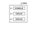
- FIG. 5 is a block diagram showing a configuration example of a mobile unit according to the embodiment of the present invention.
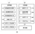
- FIG. 6 is a block diagram showing an example of the configuration of the radioactive substance distribution map creation apparatus according to the embodiment of the present invention.
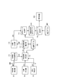
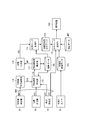
- FIG. 7 is a block diagram showing a process flow of the radioactive substance distribution map creating system according to the embodiment of the present invention.
- FIG. 1 is a conceptual view showing an outline of a radioactive substance distribution map creating system according to an embodiment of the present invention.
- FIG. 2 is a conceptual view showing an example of a radiation detector in the embodiment of the
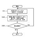
- FIG. 8 is a flowchart showing a process flow of the radioactive substance distribution map creating system according to the embodiment of the present invention.
- FIG. 9 is a flowchart showing a process flow of the radioactive substance distribution map creating apparatus according to the embodiment of the present invention.
- FIG. 10 is a block diagram showing a configuration example of a mobile unit in the modification.
- FIG. 11 is a block diagram showing the process flow of the radioactive substance distribution map creating system in the modification.
- FIG. 1 is a conceptual view showing an outline of a radioactive substance distribution map compilation system 1 according to the present embodiment.
- the radioactive substance distribution map creating system 1 includes a moving body 10 and a radioactive substance distribution map creating apparatus 100.
- An aircraft, a vehicle, a ship, etc. are illustrated as the mobile body 10.
- a radiation detector 20 for measuring radioactive substances is mounted on the movable body 10.
- a Compton camera with high sensitivity and a wide measurement range is exemplified (see Patent Document 1 and Patent Document 2).
- the radiation detector 20 in the present embodiment is not limited to the Compton camera, and may be a pinhole camera type radiation detector or the like. In any case, along with the movement of the movable body 10, the radiation detector 20 also moves, and the measurable range 25 by the radiation detector 20 also temporally changes.
- the radioactive substance distribution map creation apparatus 100 is an apparatus for creating a wide range of radioactive substance distribution maps, and is realized by a computer.
- the radioactive substance distribution map creating apparatus 100 may be mounted on the mobile unit 10 together with the radiation detector 20, or may be installed at a location different from the mobile unit 10 and communicably connected to the mobile unit 10 It is also good.
- the radioactive substance distribution map creation apparatus 100 may be configured integrally with the radiation detector 20.
- the radiation substance distribution map creating apparatus 100 creates a radioactive substance distribution map based on the measurement result by the radiation detector 20.
- the radiation substance distribution map creating apparatus 100 receives “measurement data” from the moving body 10 and the radiation detector 20.
- the measurement data includes at least the measurement result of the radiation detector 20 and the position information of the moving body 10.
- the radioactive substance distribution map creating apparatus 100 can create the radioactive substance distribution map by combining measurement data at a plurality of positions obtained as the moving body 10 moves.
- the radiation substance distribution map creating apparatus 100 calculates the direction of the radiation source based on the measurement result by the radiation detector 20. Since measurement data can be obtained at multiple locations as described above, the direction of the radiation source can also be calculated at multiple locations. Thus, the radiation substance distribution map creation apparatus 100 can accurately identify the position of the radiation source by “stereovision” based on the radiation source directions obtained at a plurality of positions. Then, the radiation substance distribution map creation apparatus 100 creates a radiation substance distribution map by combining the positions of one or more radiation sources.
- radiological material distribution map creation method is realized only when the following conditions specific to the object to be measured are satisfied: (1) Radiation is emitted radially from a radiation source (2) The radiation passes through the shield, (3) The radiation state of the radiation is maintained for a certain period (note that the target is a radioactive substance having a half life of several hours or more). Since the above conditions (1) and (2) are satisfied, the position of the radiation source can be accurately identified by stereovision based on measurement data at a plurality of positions away from the radiation source. Furthermore, since the condition (3) is satisfied, it is not necessary to observe the same radiation source at the same timing from a plurality of positions, and measurement data obtained at different timings can be used in combination. That is, a plurality of radiation detectors 20 are unnecessary for the radiation substance distribution map creating method of the present embodiment, and one radiation detector 20 is sufficient.
- FIG. 3 shows an example of measurement when the mobile object 10 is an aircraft (eg, an unmanned helicopter).
- the radiation detector 20 mounted on the aircraft By turning the aircraft around a certain area, the radiation detector 20 mounted on the aircraft repeatedly measures the radiation in the area. It is possible to rapidly create a three-dimensional distribution map of radioactive materials in a wide range based on measurement data obtained in a superimposed manner.
- FIG. 4 shows an example of measurement in the case where the moving body 10 is a vehicle (eg, a car, a railway).
- the radiation detector 20 mounted on the vehicle repeatedly measures the radiation in the vicinity of the route. It is possible to rapidly create a three-dimensional distribution map of radioactive materials in a wide range based on measurement data obtained in a superimposed manner.
- the radiation detector 20 is mounted on the moving body 10. Then, by combining measurement data at a plurality of positions obtained as the moving body 10 moves, a wide range radioactive substance distribution map is rapidly created.
- a radioactive substance distribution map can be created by combining and using measurement data obtained at different timings. Therefore, a plurality of radiation detectors 20 are unnecessary, and one radiation detector 20 is sufficient. This is preferable in terms of ease of measurement, flexibility and cost.
- the radiation detector 20 It is preferable to use a Compton camera with high sensitivity and a wide measurement range as the radiation detector 20. Thereby, the time of one measurement can be shortened, and the time of creation of the radioactive substance distribution map can be shortened.
- FIG. 5 is a block diagram showing a configuration example of the mobile unit 10 in the present embodiment.
- the radiation detector 20, the position measuring device 30, and the attitude measuring device 40 are mounted on the moving body 10.
- the radiation detector 20 measures radioactive material.
- the radiation detector 20 is exemplified by a Compton camera with high sensitivity and a wide measurement range. Compton cameras can also measure the energy of radiation.
- the radiation detector 20 in the present embodiment is not limited to the Compton camera, and may be a pinhole camera type radiation detector or the like.
- the position measurement device 30 measures the position (eg, latitude, longitude, altitude) of the mobile object 10.
- GPS Global Positioning System
- the posture measuring device 40 measures the posture angle and angular velocity of the radiation detector 20.
- a gyro sensor is exemplified as the attitude measuring device 40.
- FIG. 6 is a block diagram showing a configuration example of the radioactive substance distribution map creation device 100 in the present embodiment.
- the radioactive substance distribution map creating apparatus 100 is a computer, and includes a processing unit 110, a storage unit 120, and a display unit 130.
- the processing device 110 As the processing device 110, a CPU and a microcomputer are exemplified.
- the processing device 110 includes a radiation signal processing unit 111, a radiation source identification unit 112, a radiation intensity calculation unit 113, a nuclide analysis unit 114, a distribution map generation unit 115, and a distribution map display unit 116 as functional blocks.
- Each functional block is realized by processing device 110 executing program PROG. Details of processing by each functional block will be described later.
- the storage device 120 is exemplified by an HDD and a RAM.
- the storage device 120 stores accumulated data ITG, a radioactive substance distribution map DTB, map data MAP and the like. Details will be described later.
- the storage device 120 also stores a program PROG executed by the processing device 110.
- the program PROG may be recorded on a computer readable recording medium.
- the display device 130 is exemplified by a liquid crystal display.
- FIGS. 7 and 8 are a block diagram and a flowchart showing the processing flow by the radioactive substance distribution map creating system 1 according to the present embodiment, respectively. A processing flow according to the present embodiment will be described with reference to FIGS. 7 and 8.
- Step S10 The radiation detector 20 measures radioactive material and generates radiation measurement data NUC indicating the measurement result.
- the radiation measurement data NUC indicates the intensity (energy) of the measured radiation, the detection position on the detector, and the like. Then, the radiation detector 20 outputs the radiation measurement data NUC to the radioactive substance distribution map creating apparatus 100.
- the position measuring device 30 measures the position of the moving body 10 and generates position data POS.
- the position data POS indicates, for example, the latitude, longitude, and altitude of the mobile object 10 (that is, the radiation detector 20). Then, the position measurement device 30 outputs the position data POS to the radioactive substance distribution map creation device 100.
- the posture measuring device 40 measures the posture angle and angular velocity of the radiation detector 20, and generates posture data ATT indicating the measurement result. Then, the attitude measuring device 40 outputs the attitude data ATT to the radioactive substance distribution map creating apparatus 100.
- the measurement data MSR includes the above-mentioned radiation measurement data NUC, position data POS and attitude data ATT.
- the radioactive substance distribution map creation device 100 receives the measurement data MSR.
- Step S100 The radioactive substance distribution map creating apparatus 100 creates a radioactive substance distribution map DTB by combining measurement data MSR at a plurality of positions obtained as the mobile object 10 moves.
- the radioactive substance distribution map creation device 100 displays the created radioactive substance distribution map DTB on the display device 130.
- FIG. 9 is a flowchart showing the process in step S100.
- Step S111 Based on the radiation measurement data NUC obtained by the radiation detector 20, the radiation signal processing unit 111 calculates the incoming direction of radiation, that is, the direction of the radiation source. Then, the radiation signal processing unit 111 generates radiation source direction data DIR indicating the calculated direction of the radiation source.
- Step S112 The radiation source identification unit 112 receives radiation source direction data DIR, position data POS, and attitude data ATT. Then, the radiation source identification unit 112 associates the radiation source direction data DIR, the position data POS, and the posture data ATT with each other, and registers them in the integration data ITG.
- the integrated data ITG is a collection of data accumulated by repeated measurement.
- the radiation source identification unit 112 identifies the position of the radiation source measured this time by referring to the past data accumulated in the integrated data ITG.
- the position of the radiation source can be identified by combining the radiation source direction data DIR obtained at a plurality of positions, the position data POS, and the posture data ATT and performing stereo vision or pattern matching.
- the radiation source identification unit 112 identifies the position of the radiation source and generates radiation source position data LOC indicating the position.
- the radiation source identification unit 112 also registers the generated radiation source position data LOC in the integration data ITG.
- Step S113 The radiation intensity calculation unit 113 receives the radiation source position data LOC and the radiation measurement data NUC, associates the position of the radiation source with the intensity (energy) of the measured radiation, and registers it in the integration data ITG. At this time, when the radiation intensity regarding the same radiation source position is already registered, the radiation intensity is integrated and registered. That is, the radiation intensity calculation unit 113 integrates the radiation intensities measured for each of the identified radiation source positions. Then, the radiation intensity calculation unit 113 generates radiation intensity data INT indicating integrated radiation intensity.
- Step S114 The nuclide analysis unit 114 discriminates the nuclide of the observed radioactive substance. Specifically, the nuclide analysis unit 114 creates an energy spectrum based on the radiation intensity data INT, and determines nuclide of the radioactive substance with reference to known nuclide-specific energy data. Then, the nuclide analysis unit 114 generates nuclide analysis data SPE indicating the nuclide discrimination result.
- Step S115 The distribution map generation unit 115 combines the radiation source position data LOC registered in the integrated data ITG to create and update the radioactive substance distribution map DTB.
- the distribution map generation unit 115 may generate the radioactive substance distribution map DTB so that the radiation intensity at each radiation source can be known with reference to the radiation intensity data INT. Further, the distribution map generation unit 115 may create the radioactive substance distribution map DTB so as to be distinguishable for each nuclide, with reference to the nuclide analysis data SPE.
- Step S116 The distribution map display unit 116 displays the created radioactive substance distribution map DTB on the display device 130.
- the radioactive substance distribution map DTB is prepared to be distinguishable for each nuclide
- the radioactive substance distribution map DTB is also displayed on the display 130 so as to be distinguishable for each nuclide.
- the distribution map display unit 116 may read out map data MAP indicating a map issued by the Geographical Survey Institute and superimpose the radioactive substance distribution map DTB on the map for display.
- Step S200 Again referring to FIG. 8, when the measurement is continued (step S200; Yes), the process returns to step S10 described above. When the measurement is ended (Step S200; No), the process is ended.
- FIG. 10 is a block diagram showing a configuration example of the mobile unit 10 in the modification.
- FIG. 11 is a block diagram showing a process flow in the modification. The description overlapping with the above description is appropriately omitted.
- a visible light camera 50 is further mounted on the movable body 10.
- the visible light camera 50 captures a visible light image and generates visible light image data VIS.
- the radioactive substance distribution map creation device 100 receives visible light image data VIS.
- the distribution map display unit 116 superimposes the radioactive substance distribution map DTB on the visible light image and displays it on the display device 130 by referring to the visible light image data VIS and the attitude data ATT. As a result, the radioactive substance distribution map DTB can be displayed superimposed on the visible light image in real time at the viewpoint of the moving body 10.
- the radiation detector 20 is mounted on the moving body 10. Then, by combining the measurement data MSR at a plurality of positions obtained as the moving body 10 moves, a wide range radioactive substance distribution map DTB is rapidly created.
- the radioactive substance distribution map DTB can be created by using the measurement data MSR obtained at different timings in combination. Therefore, a plurality of radiation detectors 20 are unnecessary, and one radiation detector 20 is sufficient. This is preferable in terms of ease of measurement, flexibility and cost.
- the availability of measurement data MSR obtained at different timings means that the measurement data MSR for the same area can be accumulated for a fixed period and the measurement data MSR obtained in a superimposed manner can be used (see FIG. 3, see Figure 4). Therefore, it is possible to create a highly accurate radioactive substance distribution map DTB. For example, even in a situation where the radiation dose is small, an accurate radioactive substance distribution map DTB can be created by combining the measurement data MSR obtained in a superimposed manner.
- the availability of measurement data MSR obtained at different timings means that it is not necessary to observe radiation continuously in time. Therefore, the exposure dose of the passenger of the mobile unit 10 can be reduced. That is, according to the present embodiment, the safety when creating the radioactive substance distribution map DTB is improved.
- the radiation detector 20 It is preferable to use a Compton camera with high sensitivity and a wide measurement range as the radiation detector 20. Thereby, the time of one measurement can be shortened, and the time of creation of the radioactive substance distribution map can be shortened.
- the radioactive substance distribution map creation system 1 is in the field of nuclear power (radioactive substance visualization at the time of decontamination associated with a nuclear accident, etc., radiation dose monitor in a nuclear power plant, radiation monitor of low level radioactive waste), resources It can be applied to fields (monitoring of naturally occurring radioactive substances (NORM)), security fields (searching for concealed radioactive substances by terrorism etc., creation of a distribution map of dispersed radioactive substances), and the like.
Landscapes
- Physics & Mathematics (AREA)
- General Physics & Mathematics (AREA)
- Health & Medical Sciences (AREA)
- Life Sciences & Earth Sciences (AREA)
- High Energy & Nuclear Physics (AREA)
- Molecular Biology (AREA)
- Spectroscopy & Molecular Physics (AREA)
- Engineering & Computer Science (AREA)
- Theoretical Computer Science (AREA)
- Measurement Of Radiation (AREA)
Abstract
Description
図1は、本実施の形態に係る放射性物質分布マップ作成システム1の概要を示す概念図である。放射性物質分布マップ作成システム1は、移動体10と放射性物質分布マップ作成装置100とを備えている。
2-1.移動体10
図5は、本実施の形態における移動体10の構成例を示すブロック図である。移動体10には、放射線検出器20、位置測定器30、及び姿勢測定器40が搭載されている。
図6は、本実施の形態における放射性物質分布マップ作成装置100の構成例を示すブロック図である。放射性物質分布マップ作成装置100は、コンピュータであり、処理装置110、記憶装置120及び表示装置130を備えている。
図7及び図8は、それぞれ、本実施形態に係る放射性物質分布マップ作成システム1による処理フローを示すブロック図及びフローチャートである。図7及び図8を参照して、本実施の形態に係る処理フローを説明する。
放射線検出器20は、放射性物質の測定を行い、その測定結果を示す放射線測定データNUCを生成する。放射線測定データNUCは、測定された放射線の強度(エネルギー)や、検出器上の検出位置などを示す。そして、放射線検出器20は、放射線測定データNUCを、放射性物質分布マップ作成装置100に出力する。
放射線物質分布マップ作成装置100は、移動体10の移動に伴って得られる複数位置での測定データMSRを組み合わせることによって、放射性物質分布マップDTBを作成する。また、放射線物質分布マップ作成装置100は、作成した放射性物質分布マップDTBを、表示装置130に表示する。図9は、このステップS100における処理を示すフローチャートである。
放射線信号処理部111は、放射線検出器20によって得られた放射線測定データNUCに基づいて、放射線の飛来方向、すなわち、放射線源の方向を算出する。そして、放射線信号処理部111は、算出した放射線源の方向を示す放射線源方向データDIRを生成する。
放射線源同定部112は、放射線源方向データDIR、位置データPOS、及び姿勢データATTを受け取る。そして、放射線源同定部112は、放射線源方向データDIR、位置データPOS、及び姿勢データATTを関連付けて、積算データITGに登録する。この積算データITGは、測定の繰り返しにより蓄積されるデータのかたまりである。
放射線強度算出部113は、放射線源位置データLOCと放射線測定データNUCを受け取り、放射線源の位置と測定された放射線の強度(エネルギー)とを関連付けて、積算データITGに登録する。このとき、同じ放射線源位置に関する放射線強度が既に登録されている場合は、放射線強度を積算して登録する。つまり、放射線強度算出部113は、同定されたそれぞれの放射線源位置に関して測定された放射線強度を積算していく。そして、放射線強度算出部113は、積算放射線強度を示す放射線強度データINTを生成する。
核種分析部114は、観測された放射性物質の核種を判別する。具体的には、核種分析部114は、放射線強度データINTに基づいてエネルギースペクトルを作成し、既知の核種固有のエネルギーデータを参照して放射性物質の核種を判別する。そして、核種分析部114は、核種判別結果を示す核種分析データSPEを生成する。
分布マップ生成部115は、積算データITGに登録されている放射線源位置データLOCを組み合わせて、放射性物質分布マップDTBを作成、更新する。このとき、分布マップ生成部115は、放射線強度データINTを参照して、それぞれの放射線源での放射線強度が分かるように放射性物質分布マップDTBを作成してもよい。また、分布マップ生成部115は、核種分析データSPEを参照して、核種毎に識別可能なように放射性物質分布マップDTBを作成してもよい。
分布マップ表示部116は、作成された放射性物質分布マップDTBを表示装置130に表示する。放射性物質分布マップDTBが核種毎に識別可能なように作成されている場合、表示装置130においても、核種毎に識別可能なように放射性物質分布マップDTBは表示される。また、分布マップ表示部116は、国土地理院発行の地図を示す地図データMAPを読み出し、放射性物質分布マップDTBを地図に重ね合わせて表示してもよい。
再度図8を参照して、測定を継続する場合(ステップS200;Yes)、処理は上記のステップS10に戻る。測定を終了する場合(ステップS200;No)、処理は終了する。
次に、本実施の形態の変形例を説明する。図10は、変形例における移動体10の構成例を示すブロック図である。図11は、変形例における処理フローを示すブロック図である。上述の説明と重複する説明は適宜省略する。
以上に説明されたように、本実施の形態によれば、放射線検出器20が移動体10に搭載される。そして、移動体10の移動に伴って得られる複数位置での測定データMSRを組み合わせることによって、広範囲の放射性物質分布マップDTBが迅速に作成される。
Claims (10)
- 移動体に搭載され、放射性物質の測定を行う放射線検出器と、
前記移動体の位置を測定する位置測定器と、
前記放射線検出器による測定結果と前記位置測定器によって測定された前記移動体の位置情報とを含む測定データを受け取る放射性物質分布マップ作成装置と
を備え、
前記放射性物質分布マップ作成装置は、前記移動体の移動に伴って得られる複数位置での前記測定データを用いることによって、放射性物質の分布マップを作成する
放射性物質分布マップ作成システム。 - 請求項1に記載の放射性物質分布マップ作成システムであって、
前記放射性物質分布マップ作成装置は、前記放射線検出器による前記測定結果に基づいて放射線源の方向を算出し、前記複数位置で得られた前記放射線源の方向に基づいて前記放射線源の位置を同定し、1以上の前記放射線源の位置を組み合わせることによって前記分布マップを作成する
放射性物質分布マップ作成システム。 - 請求項1又は2に記載の放射性物質分布マップ作成システムであって、
前記放射線検出器は、コンプトンカメラである
放射性物質分布マップ作成システム。 - 請求項1乃至3のいずれか一項に記載の放射性物質分布マップ作成システムであって、
前記放射性物質分布マップ作成装置は、表示装置を備え、前記作成した分布マップを前記表示装置に表示する
放射性物質分布マップ作成システム。 - 請求項4に記載の放射性物質分布マップ作成システムであって、
前記放射線検出器による前記測定結果は、観測された放射線の強度を含み、
前記放射性物質分布マップ作成装置は、前記強度に基づいて放射性物質の核種を判別し、前記核種毎に識別可能なように前記作成した分布マップを前記表示装置に表示する
放射性物質分布マップ作成システム。 - 請求項4又は5に記載の放射性物質分布マップ作成システムであって、
前記放射性物質分布マップ作成装置は、前記作成した分布マップを地図に重ね合わせて前記表示装置に表示する
放射性物質分布マップ作成システム。 - 請求項4乃至6のいずれか一項に記載の放射性物質分布マップ作成システムであって、
更に、
前記移動体に搭載された可視光カメラ
を備え、
前記放射性物質分布マップ作成装置は、前記可視光カメラによって撮像された可視光画像を受け取り、前記作成した分布マップを前記可視光画像に重ね合わせて前記表示装置に表示する
放射性物質分布マップ作成システム。 - 請求項1乃至7のいずれか一項に記載の放射性物質分布マップ作成システムであって、
前記移動体は、航空機である
放射性物質分布マップ作成システム。 - 請求項1乃至7のいずれか一項に記載の放射性物質分布マップ作成システムであって、
前記移動体は、車両である
放射性物質分布マップ作成システム。 - 移動体に搭載された放射線検出器を用いて放射性物質の測定を行うステップと、
前記移動体の位置を測定するステップと、
ここで、測定データは、前記放射線検出器による測定結果と前記移動体の位置情報とを含み、
前記移動体の移動に伴って得られる複数位置での前記測定データを用いることによって、放射性物質の分布マップを作成するステップと
を含む
放射性物質分布マップ作成方法。
Priority Applications (3)
| Application Number | Priority Date | Filing Date | Title |
|---|---|---|---|
| CN201380071572.2A CN105026957A (zh) | 2013-01-28 | 2013-05-16 | 放射性物质分布图制作系统以及放射性物质分布图制作方法 |
| EP13873014.8A EP2950118A4 (en) | 2013-01-28 | 2013-05-16 | SYSTEM FOR PRODUCING A DISSIPATION CARD OF RADIOACTIVE MATERIAL AND METHOD FOR GENERATING A DISSIPATION CARD OF RADIOACTIVE MATERIAL |
| US14/763,623 US9990751B2 (en) | 2013-01-28 | 2013-05-16 | Radioactive substance distribution map producing system and method of producing radioactive substance distribution map |
Applications Claiming Priority (2)
| Application Number | Priority Date | Filing Date | Title |
|---|---|---|---|
| JP2013013672A JP6214877B2 (ja) | 2013-01-28 | 2013-01-28 | 放射性物質分布マップ作成システム及び放射性物質分布マップ作成方法 |
| JP2013-013672 | 2013-01-28 |
Publications (1)
| Publication Number | Publication Date |
|---|---|
| WO2014115348A1 true WO2014115348A1 (ja) | 2014-07-31 |
Family
ID=51227158
Family Applications (1)
| Application Number | Title | Priority Date | Filing Date |
|---|---|---|---|
| PCT/JP2013/063627 Ceased WO2014115348A1 (ja) | 2013-01-28 | 2013-05-16 | 放射性物質分布マップ作成システム及び放射性物質分布マップ作成方法 |
Country Status (5)
| Country | Link |
|---|---|
| US (1) | US9990751B2 (ja) |
| EP (1) | EP2950118A4 (ja) |
| JP (1) | JP6214877B2 (ja) |
| CN (1) | CN105026957A (ja) |
| WO (1) | WO2014115348A1 (ja) |
Families Citing this family (10)
| Publication number | Priority date | Publication date | Assignee | Title |
|---|---|---|---|---|
| JP6677568B2 (ja) * | 2016-04-18 | 2020-04-08 | 日立Geニュークリア・エナジー株式会社 | 放射能分布解析システムおよび放射能分布解析方法 |
| GB201611506D0 (en) * | 2016-06-30 | 2016-08-17 | Create Tech Ltd | Radiation imaging apparatus |
| JP6656419B2 (ja) * | 2016-12-21 | 2020-03-04 | 三菱電機株式会社 | 放射能分布測定装置及び方法 |
| KR102057189B1 (ko) | 2018-04-24 | 2019-12-18 | (주)엔씨스퀘어 | 무인항공기를 이용한 방사성물질 탐지방법 |
| JP7165348B2 (ja) * | 2018-09-14 | 2022-11-04 | 株式会社千代田テクノル | 放射線分布の3次元表示方法及び装置 |
| CN110045409B (zh) * | 2018-12-29 | 2025-02-11 | 同方威视技术股份有限公司 | 放射性物质监测装置、系统及其监测方法 |
| CN112180418A (zh) * | 2020-04-21 | 2021-01-05 | 宁波甬东核辐射监测有限公司 | 一种定位放射源的方法、飞行设备、地面工作站及系统 |
| KR102859985B1 (ko) * | 2023-05-04 | 2025-09-15 | 한국원자력연구원 | 전방향 방사선 탐지 기반 방사능 오염정보 가시화 장치 및 그 방법 |
| KR102606441B1 (ko) * | 2023-06-21 | 2023-11-24 | 고등기술연구원연구조합 | 방사선 측정장치 |
| KR102951443B1 (ko) * | 2023-10-31 | 2026-04-10 | 한국원자력연구원 | 이동 플랫폼 탑재형 센서 기반 전방향 방사능 방향 탐지 장치 및 그 방법 |
Citations (5)
| Publication number | Priority date | Publication date | Assignee | Title |
|---|---|---|---|---|
| JP3897245B2 (ja) | 2002-04-24 | 2007-03-22 | 三菱重工業株式会社 | 多層放射線検出器を用いたガンマ線源の距離測定装置 |
| JP2009063589A (ja) | 2008-10-31 | 2009-03-26 | Japan Aerospace Exploration Agency | 放射線源位置検出システム、及び放射線源位置検出用プローブ |
| JP2010266304A (ja) * | 2009-05-14 | 2010-11-25 | Genden Information System Co Ltd | 緊急時環境放射線モニタリングシステム及びその方法 |
| JP3181739U (ja) * | 2012-12-03 | 2013-02-21 | いであ株式会社 | 曳航式水中放射能測定システム |
| JP2013134105A (ja) * | 2011-12-26 | 2013-07-08 | Kyoto Univ | 放射線量率マップデータ収集システム |
Family Cites Families (10)
| Publication number | Priority date | Publication date | Assignee | Title |
|---|---|---|---|---|
| GB9810434D0 (en) * | 1998-05-15 | 1998-07-15 | British Nuclear Fuels Plc | Improvements in and relating to monitoring emissions |
| JP2001153952A (ja) * | 1999-11-26 | 2001-06-08 | Nippon Anzen Hosho Keibi Kk | 放射能拡散状況把握システム |
| JP2001208848A (ja) * | 2000-01-27 | 2001-08-03 | Aloka Co Ltd | 放射線測定システム及び方法 |
| JP2001311791A (ja) * | 2000-04-28 | 2001-11-09 | Hitachi Engineering & Services Co Ltd | 放射線汚染状況監視方法および装置 |
| US7994926B2 (en) * | 2007-07-05 | 2011-08-09 | Purdue Research Foundation | Nuclear detection via a system of widely distributed low cost detectors having data including gamma intensities, time stamps and geo-positions |
| US8335363B2 (en) | 2009-06-16 | 2012-12-18 | Jefferson Science Associates, Llc | Method for image reconstruction of moving radionuclide source distribution |
| US20120008828A1 (en) | 2010-04-13 | 2012-01-12 | Brian David Yanoff | Target-linked radiation imaging system |
| US20120043467A1 (en) * | 2010-08-17 | 2012-02-23 | Andrey Gueorguiev | Single plane compton camera |
| JP2012251918A (ja) * | 2011-06-06 | 2012-12-20 | Kodaira Associates Kk | 放射能量分布情報生成装置 |
| CN102692637B (zh) * | 2012-05-25 | 2014-04-16 | 西南科技大学 | 基于遥操作装置的核辐射环境虚拟重建系统及方法 |
-
2013
- 2013-01-28 JP JP2013013672A patent/JP6214877B2/ja active Active
- 2013-05-16 US US14/763,623 patent/US9990751B2/en active Active
- 2013-05-16 EP EP13873014.8A patent/EP2950118A4/en not_active Withdrawn
- 2013-05-16 CN CN201380071572.2A patent/CN105026957A/zh active Pending
- 2013-05-16 WO PCT/JP2013/063627 patent/WO2014115348A1/ja not_active Ceased
Patent Citations (5)
| Publication number | Priority date | Publication date | Assignee | Title |
|---|---|---|---|---|
| JP3897245B2 (ja) | 2002-04-24 | 2007-03-22 | 三菱重工業株式会社 | 多層放射線検出器を用いたガンマ線源の距離測定装置 |
| JP2009063589A (ja) | 2008-10-31 | 2009-03-26 | Japan Aerospace Exploration Agency | 放射線源位置検出システム、及び放射線源位置検出用プローブ |
| JP2010266304A (ja) * | 2009-05-14 | 2010-11-25 | Genden Information System Co Ltd | 緊急時環境放射線モニタリングシステム及びその方法 |
| JP2013134105A (ja) * | 2011-12-26 | 2013-07-08 | Kyoto Univ | 放射線量率マップデータ収集システム |
| JP3181739U (ja) * | 2012-12-03 | 2013-02-21 | いであ株式会社 | 曳航式水中放射能測定システム |
Non-Patent Citations (2)
| Title |
|---|
| See also references of EP2950118A4 |
| SHIN'ICHIRO TAKEDA ET AL.: "Cho Kokaku Compton Camera' ni yoru Fukushima deno Jissho Shiken", ISOTOPE NEWS, vol. 702, 1 October 2012 (2012-10-01), pages 14 - 20, XP008180490 * |
Also Published As
| Publication number | Publication date |
|---|---|
| EP2950118A4 (en) | 2016-09-21 |
| US20150363956A1 (en) | 2015-12-17 |
| EP2950118A1 (en) | 2015-12-02 |
| JP6214877B2 (ja) | 2017-10-18 |
| CN105026957A (zh) | 2015-11-04 |
| JP2014145628A (ja) | 2014-08-14 |
| US9990751B2 (en) | 2018-06-05 |
Similar Documents
| Publication | Publication Date | Title |
|---|---|---|
| JP6214877B2 (ja) | 放射性物質分布マップ作成システム及び放射性物質分布マップ作成方法 | |
| CN114502988B (zh) | 辐射源定位系统和方法 | |
| CN105510952B (zh) | 飞行模式CdZnTe巡检系统和巡检方法 | |
| US8153986B2 (en) | Hybrid Compton camera/coded aperture imaging system | |
| CN103176201B (zh) | 放射性物质巡检定位方法及设备 | |
| ES3027657T3 (en) | System and method for the volumetric and isotopic identification of radiation distribution in radioactive surroundings | |
| Pavlovsky et al. | 3-D radiation mapping in real-time with the localization and mapping platform LAMP from unmanned aerial systems and man-portable configurations | |
| US10024985B1 (en) | Gamma ray detector with two-dimensional directionality | |
| Burtniak et al. | Application of a territorial remote radiation monitoring system at the Chornobyl nuclear accident site | |
| JP2012251918A (ja) | 放射能量分布情報生成装置 | |
| JP2014145628A5 (ja) | ||
| ES2827957T3 (es) | Aparato y método para la inspección no invasiva de cuerpos sólidos mediante la obtención de imágenes mediante muones | |
| KR20160081307A (ko) | 방사선원의 3차원 영상 처리 장치 및 방법 | |
| Cooper et al. | Intelligent radiation sensor system (irss) advanced technology demonstrator (atd) | |
| Mukai et al. | Development of unmanned remote system to find radiation sources based on 4π gamma imaging | |
| ES2353189T3 (es) | Mã‰todo y dispositivo para la inspecciã“n de infraestructuras lineales. | |
| Vale et al. | Heterogeneous drone fleet for radiological inspection | |
| JP2017194289A (ja) | 放射能分布解析システムおよび放射能分布解析方法 | |
| McCann et al. | Which is better, a SCoTSS gamma imager, or an ARDUO UAV-borne directional detector? | |
| US20200292720A1 (en) | Efficient, Dual-particle Directional Detection System using a Rotating Scatter Mask | |
| KR102915522B1 (ko) | 무인 이동체 기반 3차원 선원위치 계산 및 방사능 추정 장치 및 방법 | |
| Zakariya et al. | Unmanned Aerial Vehicles (UAVs) Radiation Detection Concept: A State of Art Overview of Recent Advances | |
| Barnowski | Development and evaluation of real-time volumetric Compton gamma-ray imaging | |
| Maurer et al. | High fidelity ground deposition measurement with robots after explosive radiological dispersion | |
| Kawabata et al. | Measuring unit for synchronously collecting air dose rate and measurement position |
Legal Events
| Date | Code | Title | Description |
|---|---|---|---|
| WWE | Wipo information: entry into national phase |
Ref document number: 201380071572.2 Country of ref document: CN |
|
| 121 | Ep: the epo has been informed by wipo that ep was designated in this application |
Ref document number: 13873014 Country of ref document: EP Kind code of ref document: A1 |
|
| REEP | Request for entry into the european phase |
Ref document number: 2013873014 Country of ref document: EP |
|
| WWE | Wipo information: entry into national phase |
Ref document number: 14763623 Country of ref document: US Ref document number: 2013873014 Country of ref document: EP |
|
| NENP | Non-entry into the national phase |
Ref country code: DE |