WO2014115446A1 - モータ制御システム - Google Patents
モータ制御システム Download PDFInfo
- Publication number
- WO2014115446A1 WO2014115446A1 PCT/JP2013/083812 JP2013083812W WO2014115446A1 WO 2014115446 A1 WO2014115446 A1 WO 2014115446A1 JP 2013083812 W JP2013083812 W JP 2013083812W WO 2014115446 A1 WO2014115446 A1 WO 2014115446A1
- Authority
- WO
- WIPO (PCT)
- Prior art keywords
- motor
- value
- control system
- motor control
- monitoring device
- Prior art date
- Legal status (The legal status is an assumption and is not a legal conclusion. Google has not performed a legal analysis and makes no representation as to the accuracy of the status listed.)
- Ceased
Links
Images



Classifications
-
- H—ELECTRICITY
- H02—GENERATION; CONVERSION OR DISTRIBUTION OF ELECTRIC POWER
- H02P—CONTROL OR REGULATION OF ELECTRIC MOTORS, ELECTRIC GENERATORS OR DYNAMO-ELECTRIC CONVERTERS; CONTROLLING TRANSFORMERS, REACTORS OR CHOKE COILS
- H02P6/00—Arrangements for controlling synchronous motors or other dynamo-electric motors using electronic commutation dependent on the rotor position; Electronic commutators therefor
- H02P6/10—Arrangements for controlling torque ripple, e.g. providing reduced torque ripple
-
- B—PERFORMING OPERATIONS; TRANSPORTING
- B60—VEHICLES IN GENERAL
- B60R—VEHICLES, VEHICLE FITTINGS, OR VEHICLE PARTS, NOT OTHERWISE PROVIDED FOR
- B60R16/00—Electric or fluid circuits specially adapted for vehicles and not otherwise provided for; Arrangement of elements of electric or fluid circuits specially adapted for vehicles and not otherwise provided for
- B60R16/02—Electric or fluid circuits specially adapted for vehicles and not otherwise provided for; Arrangement of elements of electric or fluid circuits specially adapted for vehicles and not otherwise provided for electric constitutive elements
- B60R16/023—Electric or fluid circuits specially adapted for vehicles and not otherwise provided for; Arrangement of elements of electric or fluid circuits specially adapted for vehicles and not otherwise provided for electric constitutive elements for transmission of signals between vehicle parts or subsystems
-
- H—ELECTRICITY
- H02—GENERATION; CONVERSION OR DISTRIBUTION OF ELECTRIC POWER
- H02P—CONTROL OR REGULATION OF ELECTRIC MOTORS, ELECTRIC GENERATORS OR DYNAMO-ELECTRIC CONVERTERS; CONTROLLING TRANSFORMERS, REACTORS OR CHOKE COILS
- H02P29/00—Arrangements for regulating or controlling electric motors, appropriate for both AC and DC motors
- H02P29/02—Providing protection against overload without automatic interruption of supply
- H02P29/024—Detecting a fault condition, e.g. short circuit, locked rotor, open circuit or loss of load
- H02P29/027—Detecting a fault condition, e.g. short circuit, locked rotor, open circuit or loss of load the fault being an over-current
-
- H—ELECTRICITY
- H02—GENERATION; CONVERSION OR DISTRIBUTION OF ELECTRIC POWER
- H02P—CONTROL OR REGULATION OF ELECTRIC MOTORS, ELECTRIC GENERATORS OR DYNAMO-ELECTRIC CONVERTERS; CONTROLLING TRANSFORMERS, REACTORS OR CHOKE COILS
- H02P6/00—Arrangements for controlling synchronous motors or other dynamo-electric motors using electronic commutation dependent on the rotor position; Electronic commutators therefor
- H02P6/28—Arrangements for controlling current
Definitions
- the present invention relates to a motor control system for controlling driving of a motor, and more particularly to a motor control system suitable for controlling a motor for driving a vehicle.
- a necessary voltage command value is calculated by an arithmetic unit such as a microcomputer.
- the voltage command value from the microcomputer is generally sent as a PWM signal to a circuit that controls switching of a semiconductor element such as an IGBT (Insulated Gate Bipolar Transistor) arranged between the DC power source and the motor, A voltage corresponding to the voltage command value is applied.
- IGBT Insulated Gate Bipolar Transistor
- the current to be supplied to the motor is determined from the torque to be output by the motor as a current command value, and the torque to be output is determined as a torque command value by a microcomputer or an external device.
- the microcomputer has a plurality of functions such as a current command value calculation, a current value acquisition, a voltage command value calculation for matching the motor current with the current command value, and a function necessary for PWM signal output. If any of these functions becomes abnormal, an abnormality occurs in the function related to current control. When an abnormality occurs, the motor may output an unintended excessive torque due to an unintended voltage command applied to the motor in some cases, which may adversely affect the outside. Therefore, it is necessary to detect that an abnormality has occurred and to stop applying voltage to the motor to avoid unintentional excessive torque output.
- the motor when the motor is a vehicle driving motor, the motor does not output a torque different from the torque command value sent to the microcomputer from an external device that controls the vehicle system due to an abnormality in the arithmetic device. In particular, it is necessary to avoid the motor from outputting excessive torque that is not intended by the driver.
- the microcomputer diagnoses its own abnormality (hereinafter referred to as self-diagnosis) and an example in which a microcomputer abnormality is diagnosed by a monitoring device other than the microcomputer are known.
- self-diagnosis an example in which the microcomputer diagnoses its own abnormality
- a microcomputer abnormality is diagnosed by a monitoring device other than the microcomputer.
- diagnosis by the monitoring device is to detect an abnormality of the microcomputer even when the microcomputer becomes abnormal and self-diagnosis by the microcomputer cannot be performed normally.
- the current control by the microcomputer can be continued if the microcomputer is normal.
- a monitoring device receives a signal sent from a microcomputer, and the monitoring device uses a known method of performing diagnosis of the microcomputer.
- the microcomputer on the signal transmission side is normal, if the reception function of the monitoring device is abnormal or the circuit used for communication is abnormal, the result of the diagnosis by the monitoring device is abnormal. It becomes.
- Patent Document 1 In the technology of Patent Document 1, when the sub CPU detects an abnormality, it cannot be determined whether the main CPU or the sub CPU is abnormal. If the main CPU is normal and computation is possible, the actuator system may continue to operate. However, in the technique of Patent Document 1, after the sub CPU detects an abnormality of the main CPU, the sub CPU stops the operation of the actuator system by cutting off the power supply to the main CPU. Therefore, even if the diagnosis result becomes abnormal, it is required to continue the operation of the system as much as possible.
- the object of the present invention is to continue the operation of the system as much as possible even when the diagnosis result by the monitoring device becomes abnormal, to suppress the generation of unintentional excessive torque, and to reduce the manufacturing cost. It is to provide a motor control system.
- the present invention includes an overcurrent detection circuit having a function of turning off the switch when the absolute value of the detection value of the current flowing through the motor exceeds the first threshold value.
- the arithmetic device calculates the voltage command value so that the absolute value of the detected value of the current flowing through the motor is equal to or less than the second threshold value, and the diagnosis result by the monitoring device is abnormal.
- the voltage command value is calculated so that the absolute value of the detected value of the current flowing through the motor is equal to or smaller than a third threshold value that is smaller than the second threshold value.
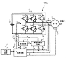
- FIG. 1 is a configuration diagram of a motor control system 100A according to the first embodiment of the present invention.
- the motor control system 100A includes a DC power source 1, an AC motor 2, an arithmetic device 3, a current sensor 4, an IGBT drive device 5, a monitoring device 6, an overcurrent detection circuit 7A, a voltage application stop switch 8, and a magnetic pole position detection sensor 9. .
- the DC power source 1 is a secondary battery such as a nickel metal hydride battery or a lithium ion battery, and its voltage is several hundred volts.
- AC motor 2 is mainly composed of two parts: a stator having three-phase windings and a rotor on which permanent magnets are arranged.
- the magnitude of the torque generated in AC motor 2 is determined by the magnitude of the current flowing through the winding, the magnitude of the permanent magnet, and the phase difference between the two.
- the relationship between the magnitude of current and the magnitude of torque is not proportional, limiting the absolute amount of current also limits the absolute amount of torque.
- the output shaft of the AC motor 2 is connected to the axle.
- the AC motor 2 is provided with a magnetic pole position detection sensor 9 for detecting the magnetic pole position of the rotor that changes as the rotor rotates.
- the computing device 3 is composed of a microcomputer or the like, and computes a voltage command value for controlling a three-phase current (Iu, Iv, Iw) supplied to the AC motor 2 based on the current command value.
- the calculation device 3 calculates the q-axis current command value Iq * and the d-axis current command value Id *, which are direct current amounts, based on the torque command value ⁇ * given from the external device 10.
- the arithmetic unit 3 uses the current detection values (Iu, Iv, Iw) detected by the current sensor 4 based on the value ⁇ of the magnetic pole position detection sensor 9 and the torque current detection value I ⁇ , which is a direct current amount, and the field current detection value If.
- the arithmetic device 3 calculates the voltage command value applied to the AC motor 2 so that the current deviation between the q-axis current and d-axis current command values (Iq *, Id *) and the detected values (Iq, Id) is zero. To do.
- the voltage command value is sent to the IGBT driving device 5 as a pulse width modulation (PWM) signal Spwm .
- PWM pulse width modulation
- the current sensor 4 detects the current flowing through the AC motor 2 and transmits the detected values (Iu, Iv, Iw) to the arithmetic device 3 and the overcurrent detection circuit 7A.
- the IGBT driving device 5 is composed of an IGBT (Insulated Gate Bipolar Transistor) or the like, and applies a voltage to the AC motor 2 using the DC power source 1 as a power source based on a PWM signal Spwm corresponding to a voltage command from the arithmetic device 3. To do.
- IGBT Insulated Gate Bipolar Transistor
- the IGBT driving device 5 (switching circuit) includes a total of six IGBTs (switching elements) that perform switching at high speed, each for three phases on the positive electrode side and the negative electrode side of the DC power supply 1 (Tr1 to Tr6). ) Is placed. A voltage corresponding to the voltage command value is applied to the AC motor 2 by switching the IGBT based on the PWM signal Spwm sent from the arithmetic device 3.
- the monitoring device 6 monitors whether the arithmetic device 3 is abnormal.
- the monitoring device 6 has a function of diagnosing the arithmetic device 3.
- the monitoring device 6 receives the pulse signal pls with a constant period transmitted from the arithmetic device 3, diagnoses whether the pulse width and period of the received pulse signal pls are within the normal range, and is not within the normal range The diagnosis result is abnormal.
- the monitoring device 6 may mistakenly diagnose that the arithmetic device 3 is abnormal even though the arithmetic device 3 is normal.
- the monitoring device 6 transmits the diagnosis result Rd to the arithmetic device 3 when the diagnosis result becomes abnormal, and enables the voltage application stop signal output function of the overcurrent detection circuit 7A when a preset time has elapsed.
- the signal S e (enable signal) is output.
- This set time needs to be longer than the time until the above-described current deviation becomes substantially zero when the arithmetic device 3 changes the current command value. For example, if the time until the current deviation is substantially 0 after the current command value is changed to 5 ms, the time is set to 10 ms, which is twice that time.
- the monitoring device 6 transmits a diagnosis result R d to that effect to the arithmetic device 3.
- the monitoring device 6 is composed of a low-function microcomputer. Since a complicated function that the arithmetic device 3 has for current control is not required, an inexpensive monitoring device 6 can be used. However, the monitoring device 6 needs a function of receiving a pulse from the arithmetic device 3 and performing a diagnostic process. Therefore, an abnormality may occur in the monitoring device 6 during pulse reception or diagnostic processing.
- the overcurrent detection circuit 7A includes a comparator, a memory, and the like, and outputs a voltage application stop signal Sstop when the current of the AC motor 2 exceeds a set threshold range.
- the overcurrent detection circuit 7A determines that an overcurrent has been detected when the current flowing through the AC motor 2 exceeds a preset current threshold range, and stops voltage application to the voltage application stop switch 8. It has a function of outputting a signal S stop . This function can be controlled effectively disabling the signal S e from the monitoring device 6. That is, when it is valid, the voltage application stop signal S stop can be output, but when it is invalid, the voltage application stop signal S stop is not output.
- the current threshold value be determined from the magnitude of torque allowed for the AC motor 2.
- the current threshold is set to a value corresponding to the magnitude of the torque that can be stopped by the driver even when the arithmetic device 3 is abnormal and generates unintended torque.
- the current threshold is equal to or greater than the value corresponding to the magnitude of torque that can drive the vehicle at a low speed when the arithmetic device 3 is normal.
- an overcurrent may be detected when a state in which the current flowing through the AC motor 2 exceeds a preset current threshold range continues for a preset time.
- the set time is preferably determined so as to prevent erroneous detection of overcurrent due to noise or the like superimposed on the current detection value.
- the voltage application stop switch 8 stops the voltage application to the AC motor 2 by the IGBT drive device 5 by interrupting the PWM signal from the arithmetic device 3 in response to the voltage application stop signal S stop . That is, the voltage application stop switch 8 turns on / off the supply of a control signal for controlling the IGBT drive device 5 from the arithmetic device 3 to the IGBT drive device 5.
- the arithmetic unit 3 and the voltage application stop switch 8 for stopping the PWM signal S pwm to transmission path of the PWM signal S pwm between the IGBT drive device 5 are connected in series, are arranged.
- this switch becomes active (open)
- the switching of the IGBTs (Tr1 to Tr6) is stopped, and the voltage application to the AC motor 2 is stopped.
- the magnetic pole position detection sensor 9 detects the magnetic pole position of the rotor and transmits the detected value ⁇ to the arithmetic device 3.
- the external device 10 gives the arithmetic device 3 a torque command value ⁇ * to be output by the AC motor.
- the external device 10 acquires various information from the arithmetic device 3.
- FIG. 2 is a diagram for explaining the operation of the motor control system 100A according to the first embodiment of the present invention when an abnormality occurs in the arithmetic device 3.
- FIG. 2A is a diagram for explaining a diagnosis result by the monitoring device 6.
- the horizontal axis represents time t, and the vertical axis represents the diagnosis result (abnormal / normal).
- the diagnosis result of the monitoring device 6 is normal before the timing T1
- the diagnosis result of the monitoring device 6 is abnormal after the timing T1.
- FIG. 2B is a diagram for explaining the operating state of the voltage application stop signal function of the overcurrent detection circuit 7A.
- the horizontal axis represents time t, and the vertical axis represents the operating state (valid / invalid) of the voltage application stop signal function.
- the timing T2 is a timing at which a predetermined time ⁇ T has elapsed from the timing T1 at which an abnormality has occurred.
- the voltage application stop signal output function of the overcurrent detection circuit 7A is invalid before the timing T2, and the voltage application stop signal output function of the overcurrent detection circuit 7A is valid after the timing T2.
- FIG. 2C is a diagram showing the detected value of the three-phase current of the AC motor 2 by the current sensor 4.
- the horizontal axis represents time t, and the vertical axis represents detected current values (Iu, Iv, Iw).
- the arithmetic device 3 performs a normal operation before the timing T1.
- the upper and lower limits of the control current range in normal operation are I_H1 and I_L1, respectively.
- the absolute values of I_H1 and I_L1 are equal.
- the arithmetic device 3 performs a limited operation.
- the upper and lower limits of the control current range in the limited operation are I_H2 and I_L2, respectively.
- the absolute values of I_H2 and I_L2 are equal.
- the absolute values of the upper and lower limits of the control current range are smaller than in normal operation. That is, the control current range during the limited operation is included in the control current range during the normal operation.
- the arithmetic device 3 determines the voltage command value so that the absolute value of the detected value of the current flowing through the motor 2 is equal to or less than the threshold value (the absolute values of I_H1 and I_L1). Is calculated.
- the arithmetic device 3 has a threshold value (absolute value of I_H2 and I_L2) where the absolute value of the detected value of the current flowing through the motor 2 is smaller than the threshold value (absolute value of I_H1 and I_L1).
- the voltage command value is calculated so as to be as follows. Thereby, the output torque of AC motor 2 is limited.
- the upper limit of the current threshold range stored in the memory of the overcurrent detection circuit 7A is indicated by a broken line Th_H
- the lower limit of the current threshold range is indicated by a broken line Th_L.
- I_H2 ⁇ Th_H and Th_L ⁇ I_L2.
- the upper limit Th_H and the lower limit Th_L of the current threshold are determined in consideration of variations in detection values of the current sensor 4 and the like.
- the absolute values of Th_H and Th_L are equal.
- the relationship of I_H2 (third threshold) ⁇ Th_H (first threshold) ⁇ I_H1 (second threshold) is established.
- the three-phase current of the AC motor 2 is within the control current range determined from the current command value.
- the monitoring device 6 transmits the diagnostic result R d to the arithmetic device 3 as shown in FIG.
- the arithmetic unit 3 sets the current command value so that the “three-phase current of the AC motor 2” is within the current threshold value range set in the overcurrent detection circuit 7A (Th_L ⁇ I ⁇ Th_H). To start limited operation.
- the arithmetic device 3 is configured so that the “three-phase current of the AC motor 2” takes into account the above-described current deviation error that occurs due to variations in detection values of the current sensor 4, the magnetic pole position sensor 9, and the like.
- the current command value is set so that the current I of 2 falls within the current threshold range of the overcurrent detection circuit 7A (Th_L ⁇ I ⁇ Th_H).
- the upper limit I_H2 of the control current range is smaller than the upper limit Th_H of the current threshold range
- the lower limit I_L2 of the control current range is larger than the lower limit Th_L of the current threshold range.
- the monitoring device 6 outputs a signal S e to enable voltage application stop signal output function to the overcurrent detection circuit 7A To do. Thereby, the monitoring apparatus 6 validates the voltage application stop signal output function of the overcurrent detection circuit 7A.
- the arithmetic device 3 is in an abnormal state at the timing T1, and the “three-phase current of the motor 2” exceeds the current threshold range of the overcurrent detection circuit 7A at the timing T2. That is, the absolute value of the detected value of the current flowing through the motor 2 exceeds the threshold value (the absolute values of Th_H and Th_L).
- the voltage application stop signal S stop is output from the overcurrent detection circuit 7A, the voltage application stop switch 8 becomes active, and the IGBT switching stops. Therefore, “three-phase current of AC motor 2” is zero, and the generated torque is zero.
- FIG. 3 is a diagram for explaining the operation of the motor control system 100A according to the first embodiment of the present invention when an abnormality occurs in the monitoring device 6.
- FIG. 3 the same parts as those in FIG.
- the calculation device 3 is normal but the monitoring device 6 becomes abnormal during motor control by the current command value calculated based on the torque command from the external device 10 after the system is started.
- the monitoring device 6 A case will be described where the diagnosis result is abnormal.
- FIG. 3A is a diagram for explaining a diagnosis result by the monitoring device 6.
- the horizontal axis represents time t, and the vertical axis represents the diagnosis result (abnormal / normal).
- the diagnosis result of the monitoring device 6 is normal before the timing T1
- the diagnosis result of the monitoring device 6 is abnormal after the timing T1.
- FIG. 3B is a diagram for explaining the operating state of the voltage application stop signal function of the overcurrent detection circuit 7A.
- the horizontal axis represents time t, and the vertical axis represents the operating state (valid / invalid) of the voltage application stop signal function.
- the voltage application stop signal output function of the overcurrent detection circuit 7A is invalid before the timing T2
- the voltage application stop signal output function of the overcurrent detection circuit 7A is valid after the timing T2.
- FIG. 3C is a diagram showing a detected value of the three-phase current of the AC motor 2 by the current sensor 4.
- the horizontal axis represents time t, and the vertical axis represents detected current values (Iu, Iv, Iw).
- the timing T1 is the same as that in FIG.
- the monitoring device 6 transmits the diagnosis result R d to the arithmetic device 3 as shown in FIG. To do.
- the arithmetic unit 3 sets the current command value so that the “three-phase current of the motor 2” is within the range of the current threshold set in the overcurrent detection circuit 7A (Th_L ⁇ I ⁇ Th_H). Start limited operation.
- the setting of the current command value at this time is the same as in the case of FIG.
- the monitoring device 6 outputs a signal S e to enable voltage application stop signal output function to the overcurrent detection circuit 7A To do. Thereby, the monitoring apparatus 6 validates the voltage application stop signal output function of the overcurrent detection circuit 7A.
- the monitoring device 6 is in an abnormal state at timing T1, but the arithmetic device 3 is normal. Therefore, the “three-phase current of the motor 2” does not exceed the current threshold range of the overcurrent detection circuit 7A. Therefore, the voltage application stop signal S stop is not output from the overcurrent detection circuit 7A. Thereby, the arithmetic unit 3 can continue the limited operation.
- the failure mode 1 is a case where the function of transmitting the diagnosis result R d to the arithmetic device 3 is not broken and the function of enabling the voltage application stop signal output function of the overcurrent detection circuit 7A is broken. . Since the arithmetic unit 3 diagnosis function of transmitting R d is not failed, the monitoring apparatus 6 is capable of diagnosis transmit R d to the arithmetic unit 3. On the other hand, since the function for enabling the voltage application stop signal output function of the overcurrent detection circuit 7A has failed, the monitoring device 6 cannot enable the voltage application stop signal output function of the overcurrent detection circuit 7A. .
- the arithmetic device 3 sets the current command value as described above, but since the arithmetic device 3 is normal, the limited operation is continued as it is.
- Embodiment 2 of failure the ability to transmit a diagnosis result R d to the arithmetic unit 3 has failed, the ability to enable the voltage application stop signal output function of the overcurrent detection circuit 7A shows the case where not failed. Since the function of transmitting the diagnosis result R d to the arithmetic unit 3 is faulty, monitoring device 6 can not be diagnostic result transmitting R d to the arithmetic unit 3. On the other hand, since the function for enabling the voltage application stop signal output function of the overcurrent detection circuit 7A has not failed, the monitoring device 6 can enable the voltage application stop signal output function of the overcurrent detection circuit 7A. .
- the arithmetic device 3 since the arithmetic device 3 does not change the setting of the current command value, the current of the “three-phase current of the motor 2” exceeds the current threshold range of the overcurrent detection circuit 7A depending on the magnitude of the current command value. Thereby, the voltage application to the motor 2 is stopped by the voltage application stop signal from the overcurrent detection circuit 7A, and it is avoided that an unintended excessive torque is generated.
- Embodiment 3 of failure the ability to transmit a diagnosis result R d to the arithmetic unit 3 has failed, the ability to enable the voltage application stop signal output function of the overcurrent detection circuit 7A shows a case where a failure. Since the function of transmitting the diagnosis result R d to the arithmetic unit 3 is faulty, monitoring device 6 can not be diagnostic result transmitting R d to the arithmetic unit 3. In addition, since the function of enabling the voltage application stop signal output function of the overcurrent detection circuit 7A has failed, the monitoring device 6 cannot enable the voltage application stop signal output function of the overcurrent detection circuit 7A. .
- the arithmetic device 3 does not change the setting of the current command value, and the voltage application stop signal output function of the overcurrent detection circuit 7A is invalid, so that normal current control (normal operation) can be continued. .
- the system operation can be continued as much as possible, and the generation of an excessive torque that is not intended can be suppressed.
- the manufacturing cost of the motor control system can be reduced.
- FIG. 4 is a configuration diagram of a motor control system 100B according to the second embodiment of the present invention.
- an overcurrent detection circuit 7B is used instead of the overcurrent detection circuit 7A as compared with the motor control system 100A shown in FIG.
- the overcurrent detection circuit 7B determines that an overcurrent has been detected when the current flowing through the AC motor 2 exceeds a preset current threshold range, and then to the voltage application stop switch 8.
- the voltage application stop signal S stop is output.
- the overcurrent detection circuit 7B stores a current threshold 1 and a current threshold 2 as current thresholds.
- the current threshold value 1 includes an upper limit value Th_H1 and a lower limit value Th_L1
- the current threshold value 2 includes an upper limit value Th_H2 and a lower limit value Th_L2.
- the absolute values of Th_H1 and Th_L1 are equal
- the absolute values of Th_H2 and Th_L2 are equal.
- the monitoring apparatus 6 of this embodiment instead of the signal S e to enable voltage application stop signal output function, and supplies a signal S th to specify the current threshold to the overcurrent detection circuit 7B.
- the overcurrent detection circuit 7B changes the current threshold to the current threshold 1 or the current threshold 2 based on the control signal S th output from the monitoring device 6.
- the monitoring device 6 sets the control signal S th so that the current threshold is set to the current threshold 1 when the diagnosis result is normal, and the current threshold is set to the current threshold 2 when the diagnosis result is abnormal. Output.
- the current threshold 1 is set to a range in which the current of the motor 2 does not exceed when the motor control is performed without abnormality (for example, a range in which the current corresponding to the maximum accelerator amount is not exceeded).
- the current threshold 2 is desirably determined from the magnitude of torque allowed for the motor even when the arithmetic device 3 may be abnormal.
- the current threshold 2 is less than or equal to a value corresponding to the magnitude of the torque that the driver can stop by braking even when the arithmetic device 3 is abnormal and generates unintended torque.
- the current threshold value 2 needs to be secured to a value corresponding to the magnitude of torque that can drive the vehicle at a low speed when the arithmetic device 3 is normal.
- an overcurrent may be detected when a state in which the current flowing through the AC motor 2 exceeds a preset current threshold range continues for a preset time, and the set time is a noise superimposed on the current detection value. It is desirable to determine so as to prevent erroneous detection of overcurrent due to the above.
- FIG. 5 is a diagram for explaining the operation of the motor control system 100B according to the second embodiment of the present invention when an abnormality occurs in the arithmetic device 3.
- FIG. 5 the same parts as those in FIG.
- FIG. 5A is a diagram for explaining a diagnosis result by the monitoring device 6.
- the horizontal axis represents time t, and the vertical axis represents the diagnosis result (abnormal / normal).
- the diagnosis result of the monitoring device 6 is normal before the timing T1
- the diagnosis result of the monitoring device 6 is abnormal after the timing T1.
- FIG. 5B is a diagram showing the detected value of the three-phase current of the AC motor 2 by the current sensor 4.
- the horizontal axis represents time t, and the vertical axis represents detected current values (Iu, Iv, Iw).
- the arithmetic device 3 is normal and the “diagnosis result of the monitoring device 6” is normal before the timing T1. Therefore, before the timing T1, the “three-phase current of the motor 2” is within the control current range (I_L1 ⁇ I ⁇ I_H1) determined from the current command value.
- the overcurrent detection circuit 7B is set to the above-described current threshold value 1 (Th_H1, Th_L1) until the timing T2, the overcurrent detection circuit 7 remains overcurrent as long as the current control is normally performed. Will not be detected.
- the monitoring device 6 sends the diagnostic result R d to the arithmetic device 3 as shown in FIG. introduce.
- the arithmetic unit 3 starts the limited operation in a state where the current command value is set so that the current of the AC motor 2 falls within the current threshold value 2 (Th_H2, Th_L2) of the overcurrent detection circuit 7B.
- the current of the motor 2 is detected as an overcurrent even if the above-described current deviation error that occurs due to variations in detection values of the current sensor 4 and the magnetic pole position sensor 9 is detected.
- the current command value is set so as to be within the range of the current threshold 2 of the circuit 7B (Th_H2, Th_L2).
- the upper limit I_H2 of the control current range is smaller than the upper limit Th_H2 of the current threshold range
- the lower limit I_L2 of the damping current range is larger than the lower limit Th_L2 of the current threshold range.
- I_H1 (second threshold) ⁇ Th_H1 (first threshold Th1)
- I_H2 (third threshold) ⁇ Th_H2 (first threshold Th2)
- I_H1 (second threshold) ⁇ I_H1 (second threshold).
- the monitoring device 6 changes the current threshold of the overcurrent detection circuit 7B from the current threshold 1 (Th_H1, Th_L1) to the current threshold 2 (Th_H2). , Th_L2).
- the arithmetic device 3 is in an abnormal state at the timing T1, and the “three-phase current of the motor 2” exceeds the upper limit Th_H2 of the current threshold 2 of the overcurrent detection circuit 7 at the timing T2.
- the voltage application stop signal S stop is output from the overcurrent detection circuit 7, the voltage application stop switch 8 becomes active, and the IGBT switching stops, so the “three-phase current of the AC motor 2” becomes zero and the generated torque Is also 0.
- FIG. 6 is a diagram for explaining the operation of the motor control system 100B according to the second embodiment of the present invention when an abnormality occurs in the monitoring device 6.
- FIG. 6 the same parts as those in FIG.
- the calculation device 3 is normal but the monitoring device 6 becomes abnormal during motor control by the current command value calculated based on the torque command from the external device 10 after the system is started.
- the monitoring device 6 A case will be described where the diagnosis result is abnormal.
- FIG. 6A is a diagram for explaining a diagnosis result by the monitoring device 6.
- the horizontal axis represents time t, and the vertical axis represents the diagnosis result (abnormal / normal).
- the diagnosis result of the monitoring device 6 is normal before the timing T1
- the diagnosis result of the monitoring device 6 is abnormal after the timing T1.
- FIG. 6B is a diagram showing the detected value of the three-phase current of the AC motor 2 by the current sensor 4.
- the horizontal axis represents time t, and the vertical axis represents detected current values (Iu, Iv, Iw).
- the process up to timing T1 is the same as that in FIG.
- the monitoring device 6 sends the diagnostic result R d to the arithmetic device 3 as shown in FIG. introduce.
- the arithmetic unit 3 starts the limited operation in a state where the current command value is set so that the current of the AC motor 2 falls within the current threshold value 2 (Th_H2, Th_L2) of the overcurrent detection circuit 7B.
- the setting of the current command value at this time is the same as in the case of FIG.
- the monitoring device 6 supplies a signal S th specifying the current threshold 2 to the overcurrent detection circuit 7B. Accordingly, the monitoring device 6 changes the current threshold value of the overcurrent detection circuit 7 from the current threshold value 1 (Th_H1, Th_L1) to the current threshold value 2 (Th_H2, Th_L2).
- the monitoring device 6 sets the absolute value of the current threshold value of the overcurrent detection circuit 7 to Th1 when the diagnosis result is normal, and sets the absolute value of the current threshold value of the overcurrent detection circuit 7 when the diagnosis result is abnormal. Change from Th1 to Th2, which is smaller than Th1.
- Th1 is the absolute value of Th_H1 and Th_L1
- Th2 is the absolute value of Th_H2 and Th_L2.
- FIG. 7 is a configuration diagram of the arithmetic device 3 used in the motor control system 100C according to the third embodiment of the present invention.
- FIG. 7 the same parts as those in FIG.
- Arithmetic unit 3 includes an arithmetic processing unit 301 1 to perform arithmetic processing for the current control.
- the monitoring device 6 is disposed inside the arithmetic device 3.
- Monitoring device 6 includes a processing unit 301 1 exactly processing unit 301 2.
- the arithmetic processing units 301 1 and 301 2 perform the same calculation, and the monitoring device 6 compares the calculation results of the two and diagnoses the arithmetic device 3 depending on whether or not there is a difference.
- the abnormality diagnosis of the arithmetic device 3 by the monitoring device 6 is performed based on the pulse signal transmitted from the arithmetic device 3 by the monitoring device 6. Diagnosis may be made.
- the monitoring device 6 gives an example to the computing device 3, the computing device 3 transmits the answer to the monitoring device 6, and the monitoring device 6 diagnoses the computing device 3 based on whether or not the answer is correct. The method may be used.
- the arithmetic device 3 transmits the limited operation state to the external device 10. This is also necessary for the external device 10 to determine the torque command value required during the limited operation.
- the configuration may be such that the external device 10 can be notified of the state of the voltage application stop signal Sstop. In this case, the external device 10 can be notified of the PWM stop regardless of the state of the arithmetic device 3.
- the present invention is applied to a three-phase AC synchronous motor with a built-in magnet.
- the present embodiment can also be applied to an induction motor without a built-in magnet or a non-three-phase AC motor. Is not limited to this.
Landscapes
- Engineering & Computer Science (AREA)
- Power Engineering (AREA)
- Mechanical Engineering (AREA)
- Control Of Ac Motors In General (AREA)
- Control Of Electric Motors In General (AREA)
Abstract
監視装置による診断結果が異常になった場合でも、可能な限りシステムの作動を継続し、意図しない過大なトルクの発生を抑制し、且つ、製造コストを抑制することができるモータ制御システムを提供する。演算装置(3)は、モータ(2)へ印加する電圧を示す電圧指令値を演算し、駆動装置(5)を制御する制御信号Spwm を電圧指令値に基づいて生成する。演算装置(3)は、監視装置(6)による診断結果Rd が正常の場合、モータ(2)に流れる電流の検出値の絶対値が第2の閾値以下になるように、電圧指令値を演算し、監視装置(6)による診断結果Rd が異常の場合、モータ(2)に流れる電流の検出値の絶対値が第2の閾値より小さい第3の閾値以下になるように、電圧指令値を演算する。
Description
本発明はモータの駆動を制御するモータ制御システムに係り、特に車両の駆動用モータを制御するのに好適なモータ制御システムに関する。
直流電源からの出力をインバータにより交流電圧に変換し、モータに交流電圧を印加することでモータ電流を制御するシステムにおいては、マイコンなどの演算装置により必要な電圧指令値を算出している。マイコンからの電圧指令値は一般的にはPWM信号として直流電源とモータの間に配置されるIGBT(Insulated Gate Bipolar Transistor)などの半導体素子のスイッチングを制御する回路に送られることで、モータには電圧指令値に応じた電圧が印加される。
モータに流すべき電流は電流指令値としてモータが出力すべきトルクから決定され、出力すべきトルクはトルク指令値としてマイコンまたは外部の装置により決定される。
マイコンは電流指令値の演算、電流値の取得、モータ電流を電流指令値に一致させるための電圧指令値演算やPWM信号出力のために必要な機能など複数の機能を有する。これらのうちいずれかの機能が異常になると、電流制御に関連する機能において異常が発生する。異常が発生した際には、場合によって意図しない電圧指令がモータに印加されることで意図しない過大なトルクをモータが出力し、外部に悪影響を与えてしまう可能性がある。そのため、異常が発生したことを検出し、モータへの電圧印加を停止し意図しない過大なトルク出力を回避する必要がある。
例えば、モータが車両の駆動用モータである場合、演算装置に異常が発生し車両システムを制御する外部装置からマイコンに送られるトルク指令値とは異なるトルクをモータが出力することがないようにする必要があり、特に運転者が意図しない過大なトルクをモータが出力することは避ける必要がある。
マイコンの異常を検出するための技術としては、マイコンが自身の異常診断を行う例(以下、自己診断という。)と、マイコン以外の監視装置によりマイコンの異常を診断する例が知られている。特に、監視装置による診断の目的は、マイコンが異常になりマイコンによる自己診断が正常にできない場合でも、マイコンの異常を検出することにある。
マイコンによる自己診断の結果が異常となった場合はマイコンに何らかの異常が発生していることが明らかなため、モータへの電圧印加を停止する必要がある。一方、監視装置による診断結果が異常となった場合、実際にマイコンが異常であるケースと監視装置またはその周辺回路になんらかの異常が発生しているケースがある。
監視装置によりマイコンの異常を診断する例では、監視装置またはその周辺回路に異常が発生している場合であっても、マイコンが正常であれば、マイコンによる電流制御が継続可能である。
例えば、マイコンから送られる信号を監視装置が受信し、監視装置がマイコンの診断を実施する公知の一手法を利用する場合を考える。この例では、信号の送信側であるマイコンが正常であっても、監視装置の受信機能が異常であったり、通信に使用する回路に異常があったりすると、結果として監視装置による診断結果は異常となる。
ここで、監視装置による診断結果が異常となった場合、マイコンが異常であるか、監視装置かその他の異常であるかの判断は困難である。そこで、従来例では、意図しない過大なトルク発生の可能性を回避するためにモータへの電圧印加を停止していた。
これに関連し、サブCPUがメインCPUの異常を検出した後、サブCPUはメインCPUへの電力供給を遮断することでアクチェエータシステムの作動を停止する技術が知られている(例えば、特許文献1参照)。
一方、3つ以上の複数のCPUが相互に監視することで、異常が発生したCPUを特定し、異常が発生していない残りのCPUが演算を継続する技術が知られている(例えば、特許文献2参照)。
特許文献1の技術では、サブCPUが異常を検出した場合、メインCPUとサブCPUのどちらが異常かは判定できない。メインCPUが正常であり演算が可能である場合、アクチェエータシステムの作動を継続できる可能性がある。しかし、特許文献1の技術では、サブCPUがメインCPUの異常を検出した後、サブCPUはメインCPUへの電力供給を遮断することでアクチェエータシステムの作動を停止していた。そこで、診断結果が異常になった場合でも、可能な限りシステムの作動を継続することが求められる。
一方で、車両の駆動用モータでは、モータ出力の停止により車両の走行が継続できなくなることで、異常箇所の修理に取り掛かるまで時間を要する可能性がある。そのため、可能な限り走行を継続すること、すなわち、可能な限りシステムの作動を継続することが求められる。併せて、意図しない過大なトルクの発生を抑制することも求められる。但し、この場合車両の高速運転は必要とされず、最低限、低速でも車両を動かせる程度のトルク出力があればよい。つまり、トルクの大きさに制限をかけた状態での運転継続ができれば良い。
特許文献2の技術では、複数CPUの相互間処理が複雑になると同時に、CPUが増えることで結果としてシステム内での異常発生の確率が上がり車両運転継続の可能性が低下する恐れがある。また、同性能のCPUを複数使用することでコスト高となることが想定される。そこで、可能な限りシステムの作動を継続し、製造コストを抑制することが求められる。
本発明の目的は、監視装置による診断結果が異常になった場合でも、可能な限りシステムの作動を継続し、意図しない過大なトルクの発生を抑制し、且つ、製造コストを抑制することができるモータ制御システムを提供することにある。
上記目的を達成するために、本発明は、モータに流れる電流の検出値の絶対値が第1の閾値を超えた場合にスイッチをオフにする機能を有する過電流検出回路を備える。演算装置は、監視装置による診断結果が正常の場合、モータに流れる電流の検出値の絶対値が第2の閾値以下になるように、電圧指令値を演算し、監視装置による診断結果が異常の場合、モータに流れる電流の検出値の絶対値が第2の閾値より小さい第3の閾値以下になるように、電圧指令値を演算する。
本発明によれば、監視装置による診断結果が異常になった場合でも、可能な限りシステムの作動を継続し、意図しない過大なトルクの発生を抑制し、且つ、製造コストを抑制することができる。上記した以外の課題、構成及び効果は、以下の実施形態の説明により明らかにされる。
〔第1の実施形態〕
以下、図1~図3を用いて、本発明の第1の実施形態であるモータ制御システム100Aの構成及び動作を説明する。以下では、ハイブリッド自動車、電気自動車などに用いられる駆動系の交流モータを制御するモータ制御システム100Aを一例として説明する。
以下、図1~図3を用いて、本発明の第1の実施形態であるモータ制御システム100Aの構成及び動作を説明する。以下では、ハイブリッド自動車、電気自動車などに用いられる駆動系の交流モータを制御するモータ制御システム100Aを一例として説明する。
最初に、図1を用いて、モータ制御システム100Aの全体構成を説明する。図1は、本発明の第1の実施形態であるモータ制御システム100Aの構成図である。
モータ制御システム100Aは、直流電源1、交流モータ2、演算装置3、電流センサ4、IGBT駆動装置5、監視装置6、過電流検出回路7A、電圧印加停止スイッチ8、磁極位置検出センサ9を備える。
直流電源1は、ニッケル水素電池やリチウムイオン電池などの2次電池であり、その電圧は数百Vである。
交流モータ2は、3相分の巻線を有するステータと永久磁石が配置されたロータの2つの部分から主として構成される。交流モータ2に発生するトルクの大きさは、巻線に流れる電流の大きさと永久磁石の大きさ、及び両者の位相差により決まる。電流の大きさとトルク大きさの関係は比例ではないが、電流の絶対量を制限するとトルクの絶対量も制限される。
交流モータ2の出力軸は、車軸に接続されている。交流モータ2には、ロータの回転により変化するロータの磁極位置を検出するための磁極位置検出センサ9が配置される。
演算装置3は、マイコンなどから構成され、交流モータ2に供給する三相電流(Iu, Iv, Iw)を電流指令値に基づいて制御するための電圧指令値を演算する。
具体的には、演算装置3は、外部装置10より与えられるトルク指令値τ*に基づき直流量であるq軸電流指令値Iq*とd軸電流指令値Id*を演算する。演算装置3は、電流センサ4により検出した電流の検出値(Iu, Iv, Iw)を磁極位置検出センサ9の値θに応じて直流量であるトルク電流検出値Iτと界磁電流検出値Ifに変換する。演算装置3は、q軸電流とd軸電流の指令値(Iq*, Id*)と検出値(Iq, Id)の電流偏差を0にするように交流モータ2へ印加する電圧指令値を演算する。電圧指令値はパルス幅変調(PWM)信号SpwmとしてIGBT駆動装置5へ送られる。
電流センサ4は、交流モータ2に流れる電流を検出し、検出値(Iu, Iv, Iw)を演算装置3及び過電流検出回路7Aへ伝達する。
IGBT駆動装置5は、IGBT(Insulated Gate Bipolar Transistor)などから構成され、演算装置3からの電圧指令に相当するPWM信号Spwmに基づいて、直流電源1を電力源として交流モータ2に電圧を印加する。
具体的には、IGBT駆動装置5(スイッチング回路)には、高速でスイッチングを行うIGBT(スイッチング素子)が、直流電源1の正極側と負極側にそれぞれ3相分ずつ合計6つ(Tr1からTr6)配置される。演算装置3から送られたPWM信号Spwmに基づきIGBTがスイッチングすることで電圧指令値に応じた電圧が交流モータ2に印加される。
監視装置6は、演算装置3の異常の有無を監視する。
具体的には、監視装置6は演算装置3を診断する機能を備えている。監視装置6は演算装置3から送信される一定の周期のパルス信号plsを受信し、受信したパルス信号plsのパルス幅と周期が正常範囲内に収まっているかを診断し、正常範囲内にない場合に診断結果は異常となる。なお、監視装置6は、自身が異常である場合、演算装置3が正常であるにもかかわらず、演算装置3が異常であると誤って診断することがある。
監視装置6は、診断結果が異常となった際には診断結果Rdを演算装置3に伝達し、予め設定した時間が経過すると過電流検出回路7Aの電圧印加停止信号出力機能を有効にする信号Se(イネーブル信号)を出力する。この設定時間は演算装置3が電流指令値を変更した際に、上述の電流偏差が略0になるまでの時間より長くする必要がある。例えば電流指令値変更後に上述の電流偏差が略0になるまでの時間を5msとすると、その2倍の10msなどに設定する。
なお、監視装置6は、診断結果が正常の場合、その旨の診断結果Rdを演算装置3に伝達する。
監視装置6は、低機能なマイコンなどから構成される。演算装置3が電流制御のために有するような複雑な機能は必要とされないため、監視装置6は安価なものを使用できる。しかし、監視装置6は、演算装置3からのパルスの受信や診断処理を実施する機能等が必要である。そのため、パルスの受信や診断処理において、監視装置6に異常が発生する可能性がある。
過電流検出回路7Aは、コンパレータ、メモリなどから構成され、交流モータ2の電流が設定された閾値の範囲を超過した際に電圧印加停止信号Sstopを出力する。
具体的には、過電流検出回路7Aは、交流モータ2に流れる電流が予め設定しておいた電流閾値の範囲を越えると過電流が検出されたものとして、電圧印加停止スイッチ8へ電圧印加停止信号Sstopを出力する機能を有する。この機能は監視装置6からの信号Seにより有効無効を制御できる。つまり、有効の場合、電圧印加停止信号Sstopを出力可能であるが、無効の場合、電圧印加停止信号Sstopの出力は実施されない。
演算装置3が異常である可能性がある場合でも、電流閾値は交流モータ2に許容されるトルクの大きさから決定されるのが望ましい。例えば、電流閾値は、演算装置3が異常であり意図しないトルクを発生した際にも運転者がブレーキにより停止できるトルクの大きさに応じた値以下に設定される。
但し、電流閾値は演算装置3が正常な場合に車両を低速で運転できるトルクの大きさに応じた値以上は確保する必要がある。また、交流モータ2に流れる電流が予め設定しておいた電流閾値の範囲を越えた状態が予め設定した時間継続すると過電流が検出されたとしてもよい。設定時間は電流検出値に重畳するノイズ等による過電流の誤検出を防止するように決定されることが望ましい。
電圧印加停止スイッチ8は、電圧印加停止信号Sstopに応答して、演算装置3からのPWM信号を遮断することでIGBT駆動装置5による交流モータ2への電圧印加を停止する。つまり、電圧印加停止スイッチ8は、演算装置3からIGBT駆動装置5へのIGBT駆動装置5を制御する制御信号の供給をオン/オフする。
具体的には、演算装置3とIGBT駆動装置5との間のPWM信号Spwmの伝達経路にPWM信号Spwmを停止する電圧印加停止スイッチ8が直列に接続され、配置される。このスイッチがアクティブ(開放)になるとIGBT(Tr1~Tr6)のスイッチングが停止し、交流モータ2への電圧印加が停止する。
磁極位置検出センサ9は、ロータの磁極位置を検出し、検出値θを演算装置3へ伝達する。
外部装置10は、演算装置3に交流モータが出力すべきトルク指令値τ*を与える。なお、外部装置10は、演算装置3から種々の情報を取得するようになっている。
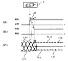
次に、図2を用いて、本発明の第1の実施形態であるモータ制御システム100Aの動作を説明する。図2は、演算装置3に異常が発生した場合における、本発明の第1の実施形態であるモータ制御システム100Aの動作を説明するための図である。
以下では、一例として、システム起動後に外部装置10からのトルク指令に基づいて演算された電流指令値によりモータ制御中のタイミングT1に演算装置3に異常が発生した場合について説明する。
図2(A)は、監視装置6による診断結果を説明するための図である。横軸は、時間tを示し、縦軸は、診断結果(異常/正常)を示す。この例では、タイミングT1以前では、監視装置6の診断結果は正常であり、タイミングT1より後では、監視装置6の診断結果は異常である。
図2(B)は、過電流検出回路7Aの電圧印加停止信号機能の動作状態を説明するための図である。横軸は、時間tを示し、縦軸は、電圧印加停止信号機能の動作状態(有効/無効)を示す。タイミングT2は、異常が発生したタイミングT1から予め設定した一定の時間ΔTが経過したタイミングである。この例では、タイミングT2以前では、過電流検出回路7Aの電圧印加停止信号出力機能は無効であり、タイミングT2より後では、過電流検出回路7Aの電圧印加停止信号出力機能は有効である。
図2(C)は、電流センサ4による交流モータ2の3相電流の検出値を表す図である。横軸は、時間tを示し、縦軸は検出した電流の検出値(Iu, Iv, Iw)を示す。この例では、タイミングT1以前では、演算装置3は通常運転を行う。通常運転における制御電流範囲の上限及び下限は、それぞれI_H1, I_L1である。本実施形態では、I_H1とI_L1の絶対値は等しい。
一方、タイミングT1より後では、演算装置3は制限運転を行う。制限運転における制御電流範囲の上限及び下限は、それぞれI_H2, I_L2である。本実施形態では、I_H2とI_L2の絶対値は等しい。
制限運転では、通常運転に比較して、制御電流範囲の上限及び下限の値の絶対値が小さくなる。つまり、制限運転時の制御電流範囲は、通常運転時の制御電流範囲に内包される。
換言すれば、演算装置3は、監視装置6による診断結果が正常の場合、モータ2に流れる電流の検出値の絶対値が閾値(I_H1及びI_L1の絶対値)以下になるように、電圧指令値を演算する。一方、演算装置3は、監視装置6による診断結果が異常の場合、モータ2に流れる電流の検出値の絶対値が閾値(I_H1及びI_L1の絶対値)より小さい閾値(I_H2及びI_L2の絶対値)以下になるように、前記電圧指令値を演算する。これにより、交流モータ2の出力トルクが制限される。
また、図2(C)では、過電流検出回路7Aのメモリに記憶された電流閾値の範囲の上限を破線Th_Hで示し、電流閾値の範囲の下限を破線Th_Lで示す。ここで、I_H2<Th_H, Th_L<I_L2である。電流閾値の上限Th_Hと下限Th_Lは、電流センサ4等の検出値のバラツキを考慮して決定される。本実施形態では、Th_HとTh_Lの絶対値は等しい。ここで、図2(C)では、I_H2(第3の閾値)<Th_H(第1の閾値)<I_H1(第2の閾値)の関係が成立する。
続いて、図2(A)~(C)を用いて、モータ制御システム100Aの動作の詳細を説明する。
図2(C)に示すように、タイミングT1より以前では、交流モータ2の3相電流は電流指令値から決定される制御電流範囲に収まっている。
タイミングT1において演算装置3に異常が発生し、「監視装置6の診断結果」が異常となると、図1に示したように、監視装置6が演算装置3に診断結果Rdを伝達する。これを受けて演算装置3は「交流モータ2の3相電流」が過電流検出回路7Aに設定された電流閾値の範囲内(Th_L<I<Th_H)になるように電流指令値を設定した状態で制限運転を開始する。
具体的には、演算装置3は、「交流モータ2の3相電流」が電流センサ4や磁極位置センサ9等の検出値のバラツキにより発生する上述の電流偏差の誤差を考慮しても交流モータ2の電流Iが過電流検出回路7Aの電流閾値の範囲内(Th_L<I<Th_H)となるように電流指令値を設定する。
ここで、図2(C)では、制御電流範囲の上限I_H2は、電流閾値の範囲の上限Th_Hよりも小さく、制御電流範囲の下限I_L2は、電流閾値の範囲の下限Th_Lよりも大きい。
次に、タイミングT1から電流偏差が0に近づくために十分な時間が経過したタイミングT2において、監視装置6は、過電流検出回路7Aに電圧印加停止信号出力機能を有効にする信号Seを出力する。これにより、監視装置6は、過電流検出回路7Aの電圧印加停止信号出力機能を有効にする。
図2(C)の例では、タイミングT1で演算装置3は異常状態であり、タイミングT2で「モータ2の3相電流」が過電流検出回路7Aの電流閾値の範囲を超える。すなわち、モータ2に流れる電流の検出値の絶対値が閾値(Th_H及びTh_Lの絶対値)を超える。
これにより、過電流検出回路7Aから電圧印加停止信号Sstopが出力され、電圧印加停止スイッチ8がアクティブになりIGBTのスイッチングは停止する。そのため、「交流モータ2の3相電流」は0となり発生トルクも0となる。
このようにして、演算装置3が異常となった際は、交流モータ2が意図しない過大なトルクを発生することを回避できる。
次に、図3を用いて、本発明の第1の実施形態であるモータ制御システム100Aの動作を説明する。図3は、監視装置6に異常が発生した場合における、本発明の第1の実施形態であるモータ制御システム100Aの動作を説明するための図である。なお、図3において、図2と同一部分には同一符号を付す。
以下では、一例として、システム起動後に外部装置10からのトルク指令に基づいて演算された電流指令値によりモータ制御中に演算装置3は正常であるが監視装置6が異常となり、結果として監視装置6の診断結果が異常となった場合について説明する。
図3(A)は、監視装置6による診断結果を説明するための図である。横軸は、時間tを示し、縦軸は、診断結果(異常/正常)を示す。この例では、タイミングT1以前では、監視装置6の診断結果は正常であり、タイミングT1より後では、監視装置6の診断結果は異常である。
図3(B)は、過電流検出回路7Aの電圧印加停止信号機能の動作状態を説明するための図である。横軸は、時間tを示し、縦軸は、電圧印加停止信号機能の動作状態(有効/無効)を示す。この例では、タイミングT2以前では、過電流検出回路7Aの電圧印加停止信号出力機能は無効であり、タイミングT2より後では、過電流検出回路7Aの電圧印加停止信号出力機能は有効である。
図3(C)は、電流センサ4による交流モータ2の3相電流の検出値を表す図である。横軸は、時間tを示し、縦軸は検出した電流の検出値(Iu, Iv, Iw)を示す。
続いて、図3(A)~(C)を用いて、モータ制御システム100Aの動作の詳細を説明する。
まず、タイミングT1までは図2と同じであるため説明は省略する。次に、タイミングT1において監視装置6に異常が発生し、「監視装置6の診断結果」が異常となると、図1に示したように、監視装置6が演算装置3に診断結果Rdを伝達する。これを受けて演算装置3は「モータ2の3相電流」が過電流検出回路7Aに設定された電流閾値の範囲内(Th_L<I<Th_H)になるように電流指令値を設定した状態で制限運転を開始する。この際の電流指令値の設定は図2の場合と同じである。
次に、タイミングT1から電流偏差が0になるために十分な時間が経過したタイミングT2において、監視装置6は、過電流検出回路7Aに電圧印加停止信号出力機能を有効にする信号Seを出力する。これにより、監視装置6は、過電流検出回路7Aの電圧印加停止信号出力機能を有効にする。
図3(C)の例では、タイミングT1で監視装置6は異常状態であるが、演算装置3は正常である。そのため、「モータ2の3相電流」が過電流検出回路7Aの電流閾値の範囲を超えない。よって、過電流検出回路7Aから電圧印加停止信号Sstopが出力されない。
これにより、演算装置3は、制限運転を継続することが可能となる。
これにより、演算装置3は、制限運転を継続することが可能となる。
次に、監視装置6に異常が発生した場合に故障の形態によって起こりうる事象を説明する。
(故障の形態1)
故障の形態1は、演算装置3へ診断結果Rdを伝達する機能は故障しておらず、過電流検出回路7Aの電圧印加停止信号出力機能を有効にする機能が故障している場合である。演算装置3へ診断結果Rdを伝達する機能は故障していないため、監視装置6は、診断結果Rdを演算装置3へ伝達することができる。一方、過電流検出回路7Aの電圧印加停止信号出力機能を有効にする機能は故障しているため、監視装置6は、過電流検出回路7Aの電圧印加停止信号出力機能を有効にすることができない。
故障の形態1は、演算装置3へ診断結果Rdを伝達する機能は故障しておらず、過電流検出回路7Aの電圧印加停止信号出力機能を有効にする機能が故障している場合である。演算装置3へ診断結果Rdを伝達する機能は故障していないため、監視装置6は、診断結果Rdを演算装置3へ伝達することができる。一方、過電流検出回路7Aの電圧印加停止信号出力機能を有効にする機能は故障しているため、監視装置6は、過電流検出回路7Aの電圧印加停止信号出力機能を有効にすることができない。
この場合、演算装置3は上述のように電流指令値を設定するが、演算装置3は正常なためそのまま制限運転が継続される。
(故障の形態2)
故障の形態2は、演算装置3へ診断結果Rdを伝達する機能は故障しており、過電流検出回路7Aの電圧印加停止信号出力機能を有効にする機能は故障していない場合である。演算装置3へ診断結果Rdを伝達する機能は故障しているため、監視装置6は、診断結果Rdを演算装置3へ伝達することができない。一方、過電流検出回路7Aの電圧印加停止信号出力機能を有効にする機能は故障していないため、監視装置6は、過電流検出回路7Aの電圧印加停止信号出力機能を有効にすることができる。
故障の形態2は、演算装置3へ診断結果Rdを伝達する機能は故障しており、過電流検出回路7Aの電圧印加停止信号出力機能を有効にする機能は故障していない場合である。演算装置3へ診断結果Rdを伝達する機能は故障しているため、監視装置6は、診断結果Rdを演算装置3へ伝達することができない。一方、過電流検出回路7Aの電圧印加停止信号出力機能を有効にする機能は故障していないため、監視装置6は、過電流検出回路7Aの電圧印加停止信号出力機能を有効にすることができる。
この場合、演算装置3は電流指令値の設定を変更しないため、電流指令値の大きさによっては、「モータ2の3相電流」の電流が過電流検出回路7Aの電流閾値の範囲を超える。これにより、過電流検出回路7Aからの電圧印加停止信号によりモータ2への電圧印加は停止し、意図しない過大なトルクを発生することは回避される。
(故障の形態3)
故障の形態3は、演算装置3へ診断結果Rdを伝達する機能は故障しており、過電流検出回路7Aの電圧印加停止信号出力機能を有効にする機能は故障している場合である。演算装置3へ診断結果Rdを伝達する機能は故障しているため、監視装置6は、診断結果Rdを演算装置3へ伝達することができない。また、過電流検出回路7Aの電圧印加停止信号出力機能を有効にする機能は故障しているため、監視装置6は、過電流検出回路7Aの電圧印加停止信号出力機能を有効にすることができない。
故障の形態3は、演算装置3へ診断結果Rdを伝達する機能は故障しており、過電流検出回路7Aの電圧印加停止信号出力機能を有効にする機能は故障している場合である。演算装置3へ診断結果Rdを伝達する機能は故障しているため、監視装置6は、診断結果Rdを演算装置3へ伝達することができない。また、過電流検出回路7Aの電圧印加停止信号出力機能を有効にする機能は故障しているため、監視装置6は、過電流検出回路7Aの電圧印加停止信号出力機能を有効にすることができない。
この場合、演算装置3は電流指令値の設定を変更せず、過電流検出回路7Aの電圧印加停止信号出力機能は無効なため、通常の電流制御(通常運転)を継続することが可能となる。
以上説明したように、本実施形態によれば、監視装置による診断結果が異常になった場合でも、可能な限りシステムの作動を継続し、意図しない過大なトルクの発生を抑制することができる。また、高機能なマイコンを複数用いないので、モータ制御システムの製造コストを削減することができる。
〔第2の実施形態〕
以下、図4~図6を用いて、本発明の第2の実施形態であるモータ制御システム100Bの構成及び動作を説明する。なお、図4において、図1と同一部分には同一符号を付す。
以下、図4~図6を用いて、本発明の第2の実施形態であるモータ制御システム100Bの構成及び動作を説明する。なお、図4において、図1と同一部分には同一符号を付す。
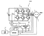
最初に、図4を用いて、モータ制御システム100Bの全体構成を説明する。図4は、本発明の第2の実施形態であるモータ制御システム100Bの構成図である。
図4に示すモータ制御システム100Bでは、図1に示すモータ制御システム100Aと比較して、過電流検出回路7Aの代わりに過電流検出回路7Bが用いられている。
過電流検出回路7Bは、過電流検出回路7Aと同様に、交流モータ2に流れる電流が予め設定しておいた電流閾値の範囲を越えると過電流が検出されたとして、電圧印加停止スイッチ8へ電圧印加停止信号Sstopを出力する機能を有する。
ただし、過電流検出回路7Bの電圧印加停止信号出力機能は常に有効である。また、過電流検出回路7Bは、電流閾値として電流閾値1と電流閾値2を記憶している。電流閾値1は、上限値Th_H1と下限値Th_L1からなり、電流閾値2は、上限値Th_H2と下限値Th_L2からなる。本実施形態では、Th_H1とTh_L1の絶対値は等しく、Th_H2とTh_L2の絶対値は等しい。
ここで、本実施形態の監視装置6は、電圧印加停止信号出力機能を有効にする信号Seの代わりに、電流閾値を指定する信号Sthを過電流検出回路7Bに供給する。過電流検出回路7Bは、監視装置6が出力する制御信号Sthに基づいて電流閾値を電流閾値1又は電流閾値2に変更する。本実施形態では、監視装置6は、診断結果が正常の場合、電流閾値を電流閾値1に設定し、診断結果が異常の場合、電流閾値を電流閾値2に設定するように制御信号Sthを出力する。
電流閾値1は異常なくモータ制御が行われている場合にモータ2の電流が超過しない範囲(例えば、最大アクセル量に応じた電流を超過しない範囲)に設定されるのが望ましい。電流閾値2は演算装置3が異常である可能性がある場合でもモータに許容されるトルクの大きさから決定されるのが望ましい。
特に、車両に適用されることを考えると、電流閾値2は、演算装置3が異常であり意図しないトルクを発生した際にも運転者がブレーキにより停止できるトルクの大きさに応じた値以下に設定する。但し、電流閾値2は演算装置3が正常な場合に車両を低速で運転できるトルクの大きさに応じた値以上を確保する必要がある。
また、交流モータ2に流れる電流が予め設定しておいた電流閾値の範囲を越えた状態が予め設定した時間継続すると過電流が検出されたとしてもよく、設定時間は電流検出値に重畳するノイズ等による過電流の誤検出を防止するように決定されることが望ましい。
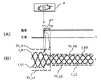
次に、図5を用いて、本発明の第2の実施形態であるモータ制御システム100Bの動作を説明する。図5は、演算装置3に異常が発生した場合における、本発明の第2の実施形態であるモータ制御システム100Bの動作を説明するための図である。なお、図5において、図2と同一部分には同一符号を付す。
以下では、一例として、システム起動後に外部装置10からのトルク指令に基づいて演算された電流指令値によりモータ制御中のタイミングT1に演算装置3に異常が発生した場合について説明する。
図5(A)は、監視装置6による診断結果を説明するための図である。横軸は、時間tを示し、縦軸は、診断結果(異常/正常)を示す。この例では、タイミングT1以前では、監視装置6の診断結果は正常であり、タイミングT1より後では、監視装置6の診断結果は異常である。
図5(B)は、電流センサ4による交流モータ2の3相電流の検出値を表す図である。横軸は、時間tを示し、縦軸は検出した電流の検出値(Iu, Iv, Iw)を示す。この例では、タイミングT1以前では、演算装置3は正常であり、「監視装置6の診断結果」は正常である。そのため、タイミングT1以前において、「モータ2の3相電流」は電流指令値から決定される制御電流範囲(I_L1<I<I_H1)に収まっている。
また、タイミングT2までは過電流検出回路7Bの電流閾値は上述の電流閾値1(Th_H1, Th_L1)に設定されているため、正常に電流制御が行われている限り過電流検出回路7が過電流を検出することはない。
次に、タイミングT1において、演算装置3に異常が発生し、「監視装置6の診断結果」が異常となると、図4に示したように、監視装置6が演算装置3に診断結果Rdを伝達する。これを受けて演算装置3は交流モータ2の電流が過電流検出回路7Bの電流閾値2(Th_H2, Th_L2)の範囲内になるように電流指令値を設定した状態で制限運転を開始する。
具体的には、「モータ2の3相電流」が電流センサ4や磁極位置センサ9等の検出値のバラツキにより発生する上述の電流偏差の誤差を考慮してもモータ2の電流が過電流検出回路7Bの電流閾値2の範囲内(Th_H2, Th_L2)となるように電流指令値を設定する。
ここで、図5(B)では、制御電流範囲の上限I_H2は、電流閾値の範囲の上限Th_H2よりも小さく、制電流範囲の下限I_L2は、電流閾値の範囲の下限Th_L2よりも大きい。また、図5(B)では、I_H1(第2の閾値)<Th_H1(第1の閾値Th1)、I_H2(第3の閾値)<Th_H2(第1の閾値Th2)<I_H1(第2の閾値)の関係が成立する。
次に、タイミングT1から電流偏差が0になるために十分な時間が経過したタイミングT2において監視装置6は過電流検出回路7Bの電流閾値を電流閾値1(Th_H1, Th_L1)から電流閾値2(Th_H2, Th_L2)に変更する。
図5(B)の例では、タイミングT1で演算装置3は異常状態であり、タイミングT2で「モータ2の3相電流」が過電流検出回路7の電流閾値2の上限Th_H2を超える。これにより、過電流検出回路7から電圧印加停止信号Sstopが出力され、電圧印加停止スイッチ8がアクティブになりIGBTのスイッチングは停止するため、「交流モータ2の3相電流」は0となり発生トルクも0となる。
このようにして、演算装置3が異常となった際でも交流モータ2が意図しない過大なトルクを発生することを回避できる。
次に、図6を用いて、本発明の第2の実施形態であるモータ制御システム100Bの動作を説明する。図6は、監視装置6に異常が発生した場合における、本発明の第2の実施形態であるモータ制御システム100Bの動作を説明するための図である。なお、図6において、図5と同一部分には同一符号を付す。
以下では、一例として、システム起動後に外部装置10からのトルク指令に基づいて演算された電流指令値によりモータ制御中に演算装置3は正常であるが監視装置6が異常となり、結果として監視装置6の診断結果が異常となった場合を説明する。
図6(A)は、監視装置6による診断結果を説明するための図である。横軸は、時間tを示し、縦軸は、診断結果(異常/正常)を示す。この例では、タイミングT1以前では、監視装置6の診断結果は正常であり、タイミングT1より後では、監視装置6の診断結果は異常である。
図6(B)は、電流センサ4による交流モータ2の3相電流の検出値を表す図である。横軸は、時間tを示し、縦軸は検出した電流の検出値(Iu, Iv, Iw)を示す。
まずタイミングT1までは図5と同じであるため説明は省略する。次に、タイミングT1において、演算装置3に異常が発生し、「監視装置6の診断結果」が異常となると、図4に示したように、監視装置6が演算装置3に診断結果Rdを伝達する。これを受けて演算装置3は交流モータ2の電流が過電流検出回路7Bの電流閾値2(Th_H2, Th_L2)の範囲内になるように電流指令値を設定した状態で制限運転を開始する。この際の電流指令値の設定は図5の場合と同じである。
次に、タイミングT1から電流偏差が0になるために十分な時間が経過したタイミングT2において、監視装置6は、電流閾値2を指定する信号Sthを過電流検出回路7Bに供給する。これにより、監視装置6は、過電流検出回路7の電流閾値を電流閾値1(Th_H1, Th_L1)から電流閾値2(Th_H2, Th_L2)に変更する。
つまり、監視装置6は、診断結果が正常の場合、過電流検出回路7の電流閾値の絶対値をTh1に設定し、診断結果が異常の場合、過電流検出回路7の電流閾値の絶対値をTh1からTh1より小さいTh2に変更する。ここで、Th1は、Th_H1及びTh_L1の絶対値であり、Th2は、Th_H2及びTh_L2の絶対値である。
演算装置3は正常であり、「モータ2の3相電流」が過電流検出回路7の電流閾値2(Th_H2, Th_L2)の範囲を超えることはないため、制限運転を継続することが可能となる。
なお、監視装置6に異常が発生した場合に故障の形態によって起こりうる事象は、第1の実施形態と同様であるため説明は省略する。
〔第3の実施形態〕
以下、図7を用いて、本発明の第3の実施形態であるモータ制御システム100Cに用いられる演算装置3の構成を説明する。図7は、本発明の第3の実施形態であるモータ制御システム100Cに用いられる演算装置3の構成図である。なお、図7において、図1と同一部分には同一符号を付す。
以下、図7を用いて、本発明の第3の実施形態であるモータ制御システム100Cに用いられる演算装置3の構成を説明する。図7は、本発明の第3の実施形態であるモータ制御システム100Cに用いられる演算装置3の構成図である。なお、図7において、図1と同一部分には同一符号を付す。
演算装置3は、電流制御のための演算処理を実行する演算処理部3011を備える。本実施形態では、監視装置6は、演算装置3の内部に配置される。監視装置6は、演算処理部3011と全く同じ演算処理部3012を有する。
演算処理部3011及び3012は同じ演算を実施し、監視装置6が両者の演算結果を比較し相違があるか否かによって演算装置3を診断する。
以上説明したように、本実施形態によれば、監視装置6を別個に設ける必要がないので、モータ制御システム100Cの製造コストを削減することができる。
以上の説明において、監視装置6による演算装置3の異常診断は監視装置6が演算装置3から送信されるパルス信号に基づいて実施するとしたが、別の公知技術により監視装置6が演算装置3を診断してもよい。例えば、監視装置6が演算装置3に対して例題を出題し、演算装置3がその解答を監視装置6に送信し、監視装置6がその解答が正しいかどうか否かによって演算装置3を診断する方法でもよい。
以上の説明において、制限運転処理が実施されている際には、外部にその情報が伝達されることが望ましい。例えば、車両に設けられた故障表示ランプを点灯するなどして運転者に制限運転状態を知らせるために、演算装置3は外部装置10に制限運転状態を伝達することが望ましい。これは制限運転中に必要なトルク指令値を外部装置10が決定するためにも必要である。また、電圧印加停止信号Sstopの状態を外部装置10に通知できる構成としてもよく、この場合は演算装置3の状態に関わらず、PWMの停止を外部装置10へ通知することができる。
以上の説明において、磁石を内蔵した3相交流同期モータに本発明を適用した場合について述べたが、磁石を内蔵しない誘導モータや3相ではない交流モータにも適用が可能であり、本実施形態はこれに限定されるものではない。
今回開示された実施の形態はすべての点で例示であって制限的なものではない。本実施形態の技術的範囲は特許請求の範囲によって規定され、そこに記載された構成と均等の範囲内のすべての変更も本実施形態の技術的範囲に含まれる。
1…直流電源
2…交流モータ
3…演算装置
4…電流センサ
5…IGBT駆動装置
6…監視装置
7…過電流検出回路
8…電圧印加停止スイッチ
9…磁極位置検出センサ
10…外部装置
301…演算処理部
2…交流モータ
3…演算装置
4…電流センサ
5…IGBT駆動装置
6…監視装置
7…過電流検出回路
8…電圧印加停止スイッチ
9…磁極位置検出センサ
10…外部装置
301…演算処理部
Claims (9)
- モータと、
前記モータへ電圧を印加する駆動装置と、
前記モータへ印加する電圧を示す電圧指令値を演算し、前記駆動装置を制御する制御信号を前記電圧指令値に基づいて生成する演算装置と、
前記演算装置と前記駆動装置の間に直列に接続され、前記演算装置から前記駆動装置への前記制御信号の供給をオン/オフするスイッチと、
前記モータに流れる電流の検出値の絶対値が第1の閾値を超えた場合に前記スイッチをオフにする機能を有する過電流検出回路と、
前記演算装置を診断する監視装置と、
を備え、
前記演算装置は、
前記監視装置による診断結果が正常の場合、前記モータに流れる電流の検出値の絶対値が第2の閾値以下になるように、前記電圧指令値を演算し、
前記監視装置による診断結果が異常の場合、前記モータに流れる電流の検出値の絶対値が前記第2の閾値より小さい第3の閾値以下になるように、前記電圧指令値を演算することを特徴とするモータ制御システム。 - 前記監視装置は、
前記診断結果が異常の場合、前記過電流検出回路の機能を有効にすることを特徴とするモータ制御システム。 - 請求項2に記載のモータ制御システムであって、
前記監視装置は、
前記診断結果が異常となったタイミングから一定の時間が経過した後に、前記過電流検出回路の機能を有効にすることを特徴とするモータ制御システム。 - 請求項2に記載のモータ制御システムであって、
前記モータは車両の駆動用モータであり、
前記第3の閾値は、
前記車両をブレーキにより停止できるトルクの大きさに応じた値以下であり、且つ、前記車両を低速で運転できるトルクの大きさに応じた値以上であることを特徴とするモータ制御システム。 - 請求項1に記載のモータ制御システムであって、
前記過電流検出回路の機能は常に有効であり、
前記監視装置は、
前記診断結果が正常の場合、前記第1の閾値をある値Th1に設定し、
前記診断結果が異常の場合、前記第1の閾値を値Th1より小さい値Th2に設定することを特徴とするモータ制御システム。 - 請求項5に記載のモータ制御システムであって、
前記監視装置は、
前記診断結果が異常となったタイミングから一定の時間が経過した後に、前記第1の閾値を値Th1より小さい値Th2に設定することを特徴とするモータ制御システム。 - 請求項5に記載のモータ制御システムであって、
前記モータは車両の駆動用モータであり、
前記第3の閾値は、
前記車両をブレーキにより停止できるトルクの大きさに応じた値以下であり、且つ、車両を低速で運転できるトルクの大きさに応じた値以上である、
ことを特徴とするモータ制御システム。 - 請求項1に記載のモータ制御システムであって、
前記第1の閾値は、前記第2の閾値より小さく、且つ、前記第3の閾値よりも大きいことを特徴とするモータ制御システム。 - 請求項5に記載のモータ制御システムであって、
前記第1の閾値としてのTh1は、前記第2の閾値より大きく、
前記第1の閾値としてのTh2は、前記第2の閾値より小さく、且つ、前記第3の閾値よりも大きいことを特徴とするモータ制御システム。
Priority Applications (2)
| Application Number | Priority Date | Filing Date | Title |
|---|---|---|---|
| US14/764,108 US9455655B2 (en) | 2013-01-28 | 2013-12-18 | Motor control system |
| EP13872770.6A EP2950444B1 (en) | 2013-01-28 | 2013-12-18 | Motor control system |
Applications Claiming Priority (2)
| Application Number | Priority Date | Filing Date | Title |
|---|---|---|---|
| JP2013013526A JP6026899B2 (ja) | 2013-01-28 | 2013-01-28 | モータ制御システム |
| JP2013-013526 | 2013-01-28 |
Publications (1)
| Publication Number | Publication Date |
|---|---|
| WO2014115446A1 true WO2014115446A1 (ja) | 2014-07-31 |
Family
ID=51227246
Family Applications (1)
| Application Number | Title | Priority Date | Filing Date |
|---|---|---|---|
| PCT/JP2013/083812 Ceased WO2014115446A1 (ja) | 2013-01-28 | 2013-12-18 | モータ制御システム |
Country Status (4)
| Country | Link |
|---|---|
| US (1) | US9455655B2 (ja) |
| EP (1) | EP2950444B1 (ja) |
| JP (1) | JP6026899B2 (ja) |
| WO (1) | WO2014115446A1 (ja) |
Cited By (2)
| Publication number | Priority date | Publication date | Assignee | Title |
|---|---|---|---|---|
| CN107005195A (zh) * | 2014-11-26 | 2017-08-01 | 日产自动车株式会社 | 电动机的控制装置以及控制方法 |
| WO2021255956A1 (ja) * | 2020-06-16 | 2021-12-23 | 株式会社日立産機システム | モータ制御装置 |
Families Citing this family (6)
| Publication number | Priority date | Publication date | Assignee | Title |
|---|---|---|---|---|
| JP6257689B2 (ja) * | 2016-04-22 | 2018-01-10 | 三菱電機株式会社 | 同期機制御装置 |
| JP6834460B2 (ja) * | 2016-12-21 | 2021-02-24 | 株式会社デンソー | 回転電機の制御装置、回転電機ユニット |
| JP6833615B2 (ja) * | 2017-05-29 | 2021-02-24 | オリンパス株式会社 | 内視鏡システム |
| JP6802135B2 (ja) * | 2017-10-11 | 2020-12-16 | 日立オートモティブシステムズ株式会社 | モータ駆動装置及びモータ駆動装置の制御方法 |
| JP6980213B2 (ja) * | 2017-12-22 | 2021-12-15 | 東芝三菱電機産業システム株式会社 | 電動機駆動装置 |
| JP7299784B2 (ja) * | 2019-07-29 | 2023-06-28 | 株式会社山田製作所 | モータ制御装置、モータ制御方法およびプログラム |
Citations (4)
| Publication number | Priority date | Publication date | Assignee | Title |
|---|---|---|---|---|
| JP3204968B2 (ja) | 1990-10-12 | 2001-09-04 | 株式会社日立製作所 | 電気自動車制御装置 |
| JP4182700B2 (ja) | 2002-07-26 | 2008-11-19 | トヨタ自動車株式会社 | 車両用システム制御装置 |
| JP2009207317A (ja) * | 2008-02-28 | 2009-09-10 | Hitachi Ltd | 車両駆動装置 |
| JP2012025374A (ja) * | 2010-06-24 | 2012-02-09 | Denso Corp | 電動機駆動装置、および、これを用いた電動パワーステアリング装置 |
Family Cites Families (7)
| Publication number | Priority date | Publication date | Assignee | Title |
|---|---|---|---|---|
| JPH07143604A (ja) * | 1993-11-12 | 1995-06-02 | Hitachi Ltd | 電気自動車制御装置 |
| US6338016B1 (en) * | 1999-03-08 | 2002-01-08 | Trw Inc. | Method and apparatus for detecting a motor stall condition in an electric assist steering system |
| JP2004312931A (ja) * | 2003-04-09 | 2004-11-04 | Toyota Motor Corp | モータ制御演算装置の異常検出装置及び異常検出方法 |
| US7990093B2 (en) | 2006-04-20 | 2011-08-02 | Mitsubishi Electric Corporation | Electric motor control apparatus |
| JP5092760B2 (ja) * | 2008-01-16 | 2012-12-05 | 株式会社ジェイテクト | モータ制御装置および電動パワーステアリング装置 |
| US8319458B2 (en) * | 2010-06-17 | 2012-11-27 | GM Global Technology Operations LLC | Vehicular electrical system and method for controlling an inverter during motor deceleration |
| JP5781875B2 (ja) * | 2011-09-14 | 2015-09-24 | トヨタ自動車株式会社 | 回転電機制御システム |
-
2013
- 2013-01-28 JP JP2013013526A patent/JP6026899B2/ja active Active
- 2013-12-18 EP EP13872770.6A patent/EP2950444B1/en active Active
- 2013-12-18 US US14/764,108 patent/US9455655B2/en active Active
- 2013-12-18 WO PCT/JP2013/083812 patent/WO2014115446A1/ja not_active Ceased
Patent Citations (4)
| Publication number | Priority date | Publication date | Assignee | Title |
|---|---|---|---|---|
| JP3204968B2 (ja) | 1990-10-12 | 2001-09-04 | 株式会社日立製作所 | 電気自動車制御装置 |
| JP4182700B2 (ja) | 2002-07-26 | 2008-11-19 | トヨタ自動車株式会社 | 車両用システム制御装置 |
| JP2009207317A (ja) * | 2008-02-28 | 2009-09-10 | Hitachi Ltd | 車両駆動装置 |
| JP2012025374A (ja) * | 2010-06-24 | 2012-02-09 | Denso Corp | 電動機駆動装置、および、これを用いた電動パワーステアリング装置 |
Cited By (5)
| Publication number | Priority date | Publication date | Assignee | Title |
|---|---|---|---|---|
| CN107005195A (zh) * | 2014-11-26 | 2017-08-01 | 日产自动车株式会社 | 电动机的控制装置以及控制方法 |
| CN107005195B (zh) * | 2014-11-26 | 2019-03-01 | 日产自动车株式会社 | 电动机的控制装置以及控制方法 |
| WO2021255956A1 (ja) * | 2020-06-16 | 2021-12-23 | 株式会社日立産機システム | モータ制御装置 |
| JP2021197840A (ja) * | 2020-06-16 | 2021-12-27 | 株式会社日立産機システム | モータ制御装置 |
| JP7246344B2 (ja) | 2020-06-16 | 2023-03-27 | 株式会社日立産機システム | モータ制御装置 |
Also Published As
| Publication number | Publication date |
|---|---|
| EP2950444A4 (en) | 2017-01-18 |
| US20150365024A1 (en) | 2015-12-17 |
| US9455655B2 (en) | 2016-09-27 |
| EP2950444A1 (en) | 2015-12-02 |
| JP6026899B2 (ja) | 2016-11-16 |
| EP2950444B1 (en) | 2020-09-30 |
| JP2014147188A (ja) | 2014-08-14 |
Similar Documents
| Publication | Publication Date | Title |
|---|---|---|
| JP6026899B2 (ja) | モータ制御システム | |
| US11387766B2 (en) | Control circuit for electric power converter | |
| JP4968698B2 (ja) | 電動機の制御装置 | |
| JP5452466B2 (ja) | ハイブリッド車両システム及びその制御方法 | |
| JP5928438B2 (ja) | 交流電動機の制御装置 | |
| US10826425B2 (en) | Drive device and control method for vehicle | |
| US20160248317A1 (en) | Control system for inverter | |
| CN113131440A (zh) | 电机控制系统与电机控制装置 | |
| US10444288B2 (en) | Abnormality diagnosing device and abnormality diagnosing method | |
| JP6983305B2 (ja) | 車両制御装置 | |
| JP2020127285A (ja) | 電動車両の制御装置 | |
| JP7276293B2 (ja) | 電力変換器の制御装置 | |
| JP2017112680A (ja) | インバータ制御装置 | |
| JP2015126642A (ja) | モータ制御装置 | |
| JP6642404B2 (ja) | 異常検出装置 | |
| JP7370775B2 (ja) | 電力変換装置、および電力変換装置の制御方法 | |
| JP2011229249A (ja) | 車両駆動システム | |
| JP2023012386A (ja) | モータ駆動システム | |
| JP2017184388A (ja) | モータ制御装置 | |
| JP2021090338A (ja) | 回転機制御装置、および、制御方法 | |
| Sharma et al. | Fail Safe Control Strategy For Torque Safety Of Electric Vehicles | |
| JP7615973B2 (ja) | 車両制御装置 | |
| JP2011259523A (ja) | モータ制御装置 | |
| JP2015073351A (ja) | モータ制御装置および車両用駆動装置 | |
| JP6409480B2 (ja) | 断線判定装置 |
Legal Events
| Date | Code | Title | Description |
|---|---|---|---|
| 121 | Ep: the epo has been informed by wipo that ep was designated in this application |
Ref document number: 13872770 Country of ref document: EP Kind code of ref document: A1 |
|
| NENP | Non-entry into the national phase |
Ref country code: DE |
|
| WWE | Wipo information: entry into national phase |
Ref document number: 14764108 Country of ref document: US Ref document number: 2013872770 Country of ref document: EP |