WO2014115622A1 - 内燃機関の排気浄化装置 - Google Patents
内燃機関の排気浄化装置 Download PDFInfo
- Publication number
- WO2014115622A1 WO2014115622A1 PCT/JP2014/050566 JP2014050566W WO2014115622A1 WO 2014115622 A1 WO2014115622 A1 WO 2014115622A1 JP 2014050566 W JP2014050566 W JP 2014050566W WO 2014115622 A1 WO2014115622 A1 WO 2014115622A1
- Authority
- WO
- WIPO (PCT)
- Prior art keywords
- filter
- exhaust
- temperature
- exhaust gas
- regeneration
- Prior art date
- Legal status (The legal status is an assumption and is not a legal conclusion. Google has not performed a legal analysis and makes no representation as to the accuracy of the status listed.)
- Ceased
Links
Images


Classifications
-
- F—MECHANICAL ENGINEERING; LIGHTING; HEATING; WEAPONS; BLASTING
- F01—MACHINES OR ENGINES IN GENERAL; ENGINE PLANTS IN GENERAL; STEAM ENGINES
- F01N—GAS-FLOW SILENCERS OR EXHAUST APPARATUS FOR MACHINES OR ENGINES IN GENERAL; GAS-FLOW SILENCERS OR EXHAUST APPARATUS FOR INTERNAL-COMBUSTION ENGINES
- F01N3/00—Exhaust or silencing apparatus having means for purifying, rendering innocuous, or otherwise treating exhaust
- F01N3/02—Exhaust or silencing apparatus having means for purifying, rendering innocuous, or otherwise treating exhaust for cooling, or for removing solid constituents of, exhaust
- F01N3/021—Exhaust or silencing apparatus having means for purifying, rendering innocuous, or otherwise treating exhaust for cooling, or for removing solid constituents of, exhaust by means of filters
- F01N3/023—Exhaust or silencing apparatus having means for purifying, rendering innocuous, or otherwise treating exhaust for cooling, or for removing solid constituents of, exhaust by means of filters using means for regenerating the filters, e.g. by burning trapped particles
- F01N3/025—Exhaust or silencing apparatus having means for purifying, rendering innocuous, or otherwise treating exhaust for cooling, or for removing solid constituents of, exhaust by means of filters using means for regenerating the filters, e.g. by burning trapped particles using fuel burner or by adding fuel to exhaust
- F01N3/0253—Exhaust or silencing apparatus having means for purifying, rendering innocuous, or otherwise treating exhaust for cooling, or for removing solid constituents of, exhaust by means of filters using means for regenerating the filters, e.g. by burning trapped particles using fuel burner or by adding fuel to exhaust adding fuel to exhaust gases
-
- F—MECHANICAL ENGINEERING; LIGHTING; HEATING; WEAPONS; BLASTING
- F01—MACHINES OR ENGINES IN GENERAL; ENGINE PLANTS IN GENERAL; STEAM ENGINES
- F01N—GAS-FLOW SILENCERS OR EXHAUST APPARATUS FOR MACHINES OR ENGINES IN GENERAL; GAS-FLOW SILENCERS OR EXHAUST APPARATUS FOR INTERNAL-COMBUSTION ENGINES
- F01N13/00—Exhaust or silencing apparatus characterised by constructional features
- F01N13/008—Mounting or arrangement of exhaust sensors in or on exhaust apparatus
-
- F—MECHANICAL ENGINEERING; LIGHTING; HEATING; WEAPONS; BLASTING
- F01—MACHINES OR ENGINES IN GENERAL; ENGINE PLANTS IN GENERAL; STEAM ENGINES
- F01N—GAS-FLOW SILENCERS OR EXHAUST APPARATUS FOR MACHINES OR ENGINES IN GENERAL; GAS-FLOW SILENCERS OR EXHAUST APPARATUS FOR INTERNAL-COMBUSTION ENGINES
- F01N3/00—Exhaust or silencing apparatus having means for purifying, rendering innocuous, or otherwise treating exhaust
- F01N3/02—Exhaust or silencing apparatus having means for purifying, rendering innocuous, or otherwise treating exhaust for cooling, or for removing solid constituents of, exhaust
- F01N3/021—Exhaust or silencing apparatus having means for purifying, rendering innocuous, or otherwise treating exhaust for cooling, or for removing solid constituents of, exhaust by means of filters
- F01N3/023—Exhaust or silencing apparatus having means for purifying, rendering innocuous, or otherwise treating exhaust for cooling, or for removing solid constituents of, exhaust by means of filters using means for regenerating the filters, e.g. by burning trapped particles
- F01N3/027—Exhaust or silencing apparatus having means for purifying, rendering innocuous, or otherwise treating exhaust for cooling, or for removing solid constituents of, exhaust by means of filters using means for regenerating the filters, e.g. by burning trapped particles using electric or magnetic heating means
-
- F—MECHANICAL ENGINEERING; LIGHTING; HEATING; WEAPONS; BLASTING
- F01—MACHINES OR ENGINES IN GENERAL; ENGINE PLANTS IN GENERAL; STEAM ENGINES
- F01N—GAS-FLOW SILENCERS OR EXHAUST APPARATUS FOR MACHINES OR ENGINES IN GENERAL; GAS-FLOW SILENCERS OR EXHAUST APPARATUS FOR INTERNAL-COMBUSTION ENGINES
- F01N3/00—Exhaust or silencing apparatus having means for purifying, rendering innocuous, or otherwise treating exhaust
- F01N3/08—Exhaust or silencing apparatus having means for purifying, rendering innocuous, or otherwise treating exhaust for rendering innocuous
- F01N3/0892—Electric or magnetic treatment, e.g. dissociation of noxious components
-
- F—MECHANICAL ENGINEERING; LIGHTING; HEATING; WEAPONS; BLASTING
- F01—MACHINES OR ENGINES IN GENERAL; ENGINE PLANTS IN GENERAL; STEAM ENGINES
- F01N—GAS-FLOW SILENCERS OR EXHAUST APPARATUS FOR MACHINES OR ENGINES IN GENERAL; GAS-FLOW SILENCERS OR EXHAUST APPARATUS FOR INTERNAL-COMBUSTION ENGINES
- F01N9/00—Electrical control of exhaust gas treating apparatus
- F01N9/002—Electrical control of exhaust gas treating apparatus of filter regeneration
-
- F—MECHANICAL ENGINEERING; LIGHTING; HEATING; WEAPONS; BLASTING
- F01—MACHINES OR ENGINES IN GENERAL; ENGINE PLANTS IN GENERAL; STEAM ENGINES
- F01N—GAS-FLOW SILENCERS OR EXHAUST APPARATUS FOR MACHINES OR ENGINES IN GENERAL; GAS-FLOW SILENCERS OR EXHAUST APPARATUS FOR INTERNAL-COMBUSTION ENGINES
- F01N2240/00—Combination or association of two or more different exhaust treating devices, or of at least one such device with an auxiliary device, not covered by indexing codes F01N2230/00 or F01N2250/00, one of the devices being
- F01N2240/16—Combination or association of two or more different exhaust treating devices, or of at least one such device with an auxiliary device, not covered by indexing codes F01N2230/00 or F01N2250/00, one of the devices being an electric heater, i.e. a resistance heater
-
- F—MECHANICAL ENGINEERING; LIGHTING; HEATING; WEAPONS; BLASTING
- F01—MACHINES OR ENGINES IN GENERAL; ENGINE PLANTS IN GENERAL; STEAM ENGINES
- F01N—GAS-FLOW SILENCERS OR EXHAUST APPARATUS FOR MACHINES OR ENGINES IN GENERAL; GAS-FLOW SILENCERS OR EXHAUST APPARATUS FOR INTERNAL-COMBUSTION ENGINES
- F01N2560/00—Exhaust systems with means for detecting or measuring exhaust gas components or characteristics
- F01N2560/06—Exhaust systems with means for detecting or measuring exhaust gas components or characteristics the means being a temperature sensor
-
- F—MECHANICAL ENGINEERING; LIGHTING; HEATING; WEAPONS; BLASTING
- F01—MACHINES OR ENGINES IN GENERAL; ENGINE PLANTS IN GENERAL; STEAM ENGINES
- F01N—GAS-FLOW SILENCERS OR EXHAUST APPARATUS FOR MACHINES OR ENGINES IN GENERAL; GAS-FLOW SILENCERS OR EXHAUST APPARATUS FOR INTERNAL-COMBUSTION ENGINES
- F01N2560/00—Exhaust systems with means for detecting or measuring exhaust gas components or characteristics
- F01N2560/12—Other sensor principles, e.g. using electro conductivity of substrate or radio frequency
-
- F—MECHANICAL ENGINEERING; LIGHTING; HEATING; WEAPONS; BLASTING
- F01—MACHINES OR ENGINES IN GENERAL; ENGINE PLANTS IN GENERAL; STEAM ENGINES
- F01N—GAS-FLOW SILENCERS OR EXHAUST APPARATUS FOR MACHINES OR ENGINES IN GENERAL; GAS-FLOW SILENCERS OR EXHAUST APPARATUS FOR INTERNAL-COMBUSTION ENGINES
- F01N2900/00—Details of electrical control or of the monitoring of the exhaust gas treating apparatus
- F01N2900/06—Parameters used for exhaust control or diagnosing
- F01N2900/14—Parameters used for exhaust control or diagnosing said parameters being related to the exhaust gas
- F01N2900/1404—Exhaust gas temperature
-
- F—MECHANICAL ENGINEERING; LIGHTING; HEATING; WEAPONS; BLASTING
- F01—MACHINES OR ENGINES IN GENERAL; ENGINE PLANTS IN GENERAL; STEAM ENGINES
- F01N—GAS-FLOW SILENCERS OR EXHAUST APPARATUS FOR MACHINES OR ENGINES IN GENERAL; GAS-FLOW SILENCERS OR EXHAUST APPARATUS FOR INTERNAL-COMBUSTION ENGINES
- F01N2900/00—Details of electrical control or of the monitoring of the exhaust gas treating apparatus
- F01N2900/06—Parameters used for exhaust control or diagnosing
- F01N2900/16—Parameters used for exhaust control or diagnosing said parameters being related to the exhaust apparatus, e.g. particulate filter or catalyst
- F01N2900/1606—Particle filter loading or soot amount
-
- Y—GENERAL TAGGING OF NEW TECHNOLOGICAL DEVELOPMENTS; GENERAL TAGGING OF CROSS-SECTIONAL TECHNOLOGIES SPANNING OVER SEVERAL SECTIONS OF THE IPC; TECHNICAL SUBJECTS COVERED BY FORMER USPC CROSS-REFERENCE ART COLLECTIONS [XRACs] AND DIGESTS
- Y02—TECHNOLOGIES OR APPLICATIONS FOR MITIGATION OR ADAPTATION AGAINST CLIMATE CHANGE
- Y02T—CLIMATE CHANGE MITIGATION TECHNOLOGIES RELATED TO TRANSPORTATION
- Y02T10/00—Road transport of goods or passengers
- Y02T10/10—Internal combustion engine [ICE] based vehicles
- Y02T10/40—Engine management systems
Definitions
- the present invention relates to an exhaust gas purification apparatus for an internal combustion engine, and more particularly to an exhaust gas purification apparatus including a filter that collects particulate matter in exhaust gas discharged from the internal combustion engine.
- DPF diesel particulate filter
- PM particulate matter
- DPF has a limit on the amount of collected PM
- forced regeneration unburned fuel (mainly HC) is supplied to the oxidation catalyst on the exhaust upstream side by injection in the exhaust pipe or post injection, and the temperature of the exhaust gas is raised to the PM combustion temperature by the heat generated by oxidation.
- the PM accumulation amount is estimated based on the pressure difference between the upstream and downstream sides of the DPF, the operation time (or the operation distance), and the forced regeneration is performed when the PM accumulation amount exceeds a predetermined amount.
- An exhaust purification device that performs the above is disclosed.
- the flow rate of the exhaust gas flowing through the DPF varies depending on the operating state of the engine.
- the differential pressure sensor that detects the differential pressure upstream and downstream of the exhaust of the DPF may not be able to accurately estimate the PM deposition amount.
- the forced regeneration start control based on the operation time (or the operation distance)
- the forced regeneration is executed in a state where the temperature of the exhaust gas is low. Therefore, in order to raise the low temperature exhaust gas to the PM combustion temperature, it is necessary to secure a large amount of fuel supply, which may lead to deterioration of fuel consumption.
- the present invention has been made in view of these points, and an object thereof is to improve the estimation accuracy of the PM accumulation amount and to optimize the fuel supply amount at the time of forced regeneration.
- an exhaust gas purification apparatus for an internal combustion engine is provided in an exhaust passage of the internal combustion engine, a filter that collects particulate matter in the exhaust gas, and an exhaust upstream side of the filter.
- An exhaust temperature detecting means provided in the exhaust passage for detecting the exhaust temperature, a capacitance detecting means for detecting the capacitance of the filter, and collected on the filter based on the detected capacitance.
- Deposit amount estimating means for estimating the amount of deposited particulate matter, filter regeneration means capable of performing forced regeneration by supplying fuel to the filter and raising the temperature of the filter to the combustion temperature of the particulate matter;
- the filter regeneration means includes a deposition amount threshold smaller than an upper limit deposition amount of the particulate matter, and a predetermined high amount capable of burning and removing particulate matter deposited up to the deposition amount threshold even if the fuel supply amount is suppressed.
- Exhaust gas temperature Based on the corresponding temperature threshold, with the amount of the deposit has reached the deposition amount threshold that is estimated, the exhaust gas temperature is detected and executes the forced regeneration to reach the temperature threshold value.
- a correction means for correcting the temperature threshold value may be further provided.
- the capacitance detection means may include a pair of electrodes that are disposed opposite to each other with at least one partition wall in the filter and form a capacitor.
- the exhaust passage on the upstream side and the downstream side of the filter is connected to bypass the filter, and the particulate matter in the exhaust gas that is provided in the bypass passage and flows through the bypass passage.
- a second filter for collecting, and the pair of electrodes may be arranged to face each other with at least one partition wall interposed in the second filter.
- the pair of electrodes may function as a heater.
- the exhaust gas purification apparatus for an internal combustion engine of the present invention it is possible to improve the estimation accuracy of the PM accumulation amount and optimize the fuel supply amount during forced regeneration.
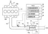
- FIG. 1 is a schematic overall configuration diagram showing an exhaust emission control device for an internal combustion engine according to an embodiment of the present invention. It is a figure which shows the map which estimates PM deposition amount from an electrostatic capacitance in the exhaust gas purification apparatus of the internal combustion engine which concerns on one Embodiment of this invention.
- the exhaust gas purification apparatus for an internal combustion engine according to an embodiment of the present invention (a) shows a change in the amount of accumulated PM, and (b) shows a change in the exhaust temperature.
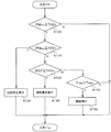
- It is a flowchart which shows the control content by the exhaust gas purification apparatus of the internal combustion engine which concerns on one Embodiment of this invention.
- It is a typical whole block diagram which shows the exhaust gas purification apparatus of the internal combustion engine which concerns on other embodiment.
- a diesel engine (hereinafter simply referred to as an engine) 10 is provided with an intake manifold 10a and an exhaust manifold 10b.
- An intake passage 11 for introducing fresh air is connected to the intake manifold 10a, and an exhaust passage 12 for releasing exhaust gas to the atmosphere is connected to the exhaust manifold 10b.
- the exhaust passage 12 is provided with an exhaust pipe injection device 13, an exhaust temperature sensor 19, and an exhaust aftertreatment device 14 in order from the exhaust upstream side.
- the exhaust pipe injection device 13 injects unburned fuel (mainly HC) into the exhaust passage 12 in response to an instruction signal output from the ECU 20.
- unburned fuel mainly HC
- this in-pipe injection device 13 may be omitted.
- the exhaust temperature sensor 19 detects the temperature of the exhaust gas flowing in the exhaust passage 12 upstream of the exhaust aftertreatment device 14.
- the exhaust temperature EGT detected by the exhaust temperature sensor 19 is input to an electronic control unit (hereinafter referred to as ECU) 20 that is electrically connected.
- the exhaust aftertreatment device 14 is configured by arranging an oxidation catalyst 15 and a DPF 16 in order from the exhaust upstream side in a case 14a.
- the oxidation catalyst 15 is formed, for example, by supporting a catalyst component on the surface of a ceramic carrier such as a cordierite honeycomb structure.
- a ceramic carrier such as a cordierite honeycomb structure.
- the DPF 16 is an example of the filter of the present invention. For example, a large number of cells partitioned by porous partition walls are arranged along the flow direction of the exhaust gas, and the upstream side and the downstream side of these cells are alternately arranged. It is formed by plugging.
- the DPF 16 collects PM in the exhaust gas in the pores and surfaces of the partition walls, and performs so-called forced regeneration that burns and removes the PM when the PM accumulation amount reaches a predetermined amount.
- the forced regeneration is performed by supplying unburned fuel (mainly HC) to the oxidation catalyst 15 by the exhaust pipe injection device 13 or post injection, and raising the DPF 16 to the PM combustion temperature (for example, about 600 ° C.).
- the DPF 16 of the present embodiment is provided with a pair of electrodes 17a and 17b that are disposed to face each other with at least one partition wall therebetween to form a capacitor.
- the pair of electrodes 17a and 17b are electrically connected to the ECU 20, respectively.
- the ECU 20 performs various controls such as fuel injection of the engine 10 and the exhaust pipe injection device 13, and includes a known CPU, ROM, RAM, input port, output port, and the like.
- the ECU 20 includes a capacitance calculation unit 21, a PM accumulation amount estimation unit 22, a regeneration control unit 23, and a threshold correction unit 24 as some functional elements.
- Each of these functional elements will be described as being included in the ECU 20 which is an integral hardware, but any one of these may be provided in separate hardware.
- the capacitance calculation unit 21 and the electrodes 17a and 17b constitute the capacitance detection means of the present invention.
- the regeneration control unit 23 and the exhaust pipe injection device 13 constitute the filter regeneration means of the present invention.
- the electrostatic capacity calculator 21 calculates the electrostatic capacity C between the electrodes 17a and 17b based on signals input from the pair of electrodes 17a and 17b.
- the electrostatic capacity C is calculated by the following formula 1, which is the dielectric constant ⁇ of the medium between the electrodes 17a and 17b, the area S of the electrodes 17a and 17b, and the distance d between the electrodes 17a and 17b.
- the PM accumulation amount estimation unit 22 calculates the PM accumulation amount PM DEP collected by the DPF 16 based on the capacitance C calculated by the capacitance calculation unit 21. For example, when conductive carbon is deposited between the electrodes 17a and 17b, the distance d between the electrodes 17a and 17b is substantially shortened and the capacitance C is increased. Further, when PM is deposited in the medium between the electrodes 17a and 17b, the capacitance C increases as the dielectric constant ⁇ increases. That is, there is a proportional relationship between the capacitance C and the PM deposition amount PM DEP, and if the capacitance C is calculated, the PM deposition amount PM DEP can be easily estimated.
- the ECU 20 stores a map (see FIG.
- the PM deposition amount estimation unit 22 reads the PM deposition amount PM DEP corresponding to the capacitance C calculated by the capacitance calculation unit 21 from this map.
- the regeneration control unit 23 controls forced regeneration of the DPF 16 based on the exhaust gas temperature EGT input from the exhaust gas temperature sensor 19 and the PM accumulation amount PM DEP estimated by the PM accumulation amount estimation unit 22. More specific control contents will be described with reference to FIG.
- the ECU 20 includes a first regeneration execution threshold value THV 1 indicated by a broken line A in FIG. 3A and a second regeneration execution threshold value THV 2 indicated by a broken line B in FIG. ), An exhaust gas temperature threshold THV 3 (temperature threshold of the present invention) indicated by a broken line C in FIG. 3B is stored in advance.
- the first regeneration execution threshold THV 1 corresponds to the upper limit accumulation amount of PM that can be collected in the DPF 16.
- the second regeneration execution threshold THV 2 corresponds to a PM accumulation amount that can suppress the fuel supply amount when forced regeneration is performed in an operation state where the exhaust gas temperature EGT is a predetermined high temperature (for example, about 400 ° C.). It is smaller than the reproduction execution threshold THV 1.
- the exhaust temperature threshold THV 3 is set to a high exhaust temperature (for example, about 400 ° C.) at which the PM accumulated up to the second regeneration execution threshold THV 2 can be removed by combustion even if the fuel supply amount is suppressed when performing forced regeneration. Equivalent to.
- the regeneration control unit 23 When the PM accumulation amount PM DEP reaches the first regeneration execution threshold value THV 1 (PM DEP ⁇ THV 1 ), the regeneration control unit 23 performs forced regeneration regardless of the exhaust gas temperature EGT (FIG. 3 (a), ( Refer to time T3 in b)). Further, the regeneration control unit 23, when the PM accumulation amount PM DEP is equal to or greater than the second regeneration execution threshold value THV 2 and less than the first regeneration execution threshold value THV 1 (THV 2 ⁇ PM DEP ⁇ THV 1 ), Is the exhaust temperature threshold THV 3 or more (EGT ⁇ THV 3 ), the forced regeneration is executed (see times T1 and T2 in FIG. 3B).
- the exhaust temperature EGT remains When the threshold value is less than THV 3 (EGT ⁇ THV 3 ), forced regeneration is suspended (see times T1 and T2 on the broken line Y in FIG. 3B). That is, when the exhaust gas temperature EGT is low, the forced regeneration is forgotten, and when the exhaust gas temperature EGT rises due to a change in the operation state thereafter, the forced regeneration is executed. Thereby, the fuel supply amount at the time of forced regeneration can be effectively suppressed.
- the threshold correction unit 24 corrects the exhaust temperature threshold THV 3 based on a time during which forced regeneration is not continuously performed (hereinafter referred to as a regeneration non-execution period T NRE ).
- the regeneration non-execution time T NRE is calculated by integrating the time counted by the timer counter from when the ignition key is turned ON (including when forced regeneration ends).
- the ECU 20 stores in advance an upper limit time T MAX that allows the forced regeneration not to be performed.
- T MAX When the regeneration non-execution time T NRE exceeds the upper limit time T MAX (T NRE > T MAX ), the threshold correction unit 24 corrects the exhaust temperature threshold THV 3 to be low.
- the maximum value (see ⁇ in FIG. 3B) of the exhaust gas temperature EGT during the forced regeneration non-execution period is stored, and the exhaust gas temperature threshold value THV 3 is set to this maximum value. It is preferable to correct downward.
- step (hereinafter, the step is simply referred to as S) 100 it is determined whether or not the PM accumulation amount PM DEP estimated from the capacitance C has reached the second regeneration execution threshold value THV2.
- the control proceeds to S110.
- the PM accumulation amount PM DEP is less than the second regeneration execution threshold value THV 2 (NO)
- this control is returned.
- the exhaust gas temperature EGT whether reaches the exhaust temperature threshold value THV 3 is determined.
- the control proceeds to S140, and forced regeneration is executed and the process returns.
- the control proceeds to S150. That is, forced regeneration is suspended.
- forced regeneration start control is performed based on the DPF differential pressure and operation time.
- the exhaust gas flow rate changes with the operating state, there is a possibility that the PM accumulation amount cannot be accurately estimated from the DPF differential pressure.
- forced regeneration start control based on the driving time (or driving distance)
- forced regeneration may be executed even when the exhaust temperature is low, and the fuel consumption may deteriorate due to an increase in the fuel supply amount. .
- the exhaust emission control device of this embodiment estimates the PM deposition amount PM DEP from the capacitance C between the pair of electrodes 17a and 17b provided in the DPF 16. Further, even if the estimated PM accumulation amount PM DEP reaches the second regeneration execution threshold value THV 2 , forced regeneration is forgotten when the exhaust gas temperature EGT is low (less than THV 3 ), while the exhaust gas temperature EGT reduces the fuel supply amount. When a high temperature state (THV 3 or more) that can be suppressed is reached, forced regeneration is performed.
- the PM accumulation amount PM DEP can be estimated with high accuracy and the fuel supply amount can be suppressed based on the capacitance C that is not affected by the change in the operating state.
- the exhaust purifying apparatus of the present embodiment when the forced regeneration is not performed continues for a predetermined period of time is configured to correct a low exhaust gas temperature threshold value THV 3.
- a bypass passage 18 that bypasses the DPF 16 may be connected to the exhaust passage 12, and the bypass passage 18 may include a measurement DPF 16 a (second filter) having a small capacity.
- the pair of electrodes 17a and 17b are arranged opposite to each other with at least one partition wall in the measurement DPF 16a, and an orifice 18a (throttle) for adjusting the flow rate of the exhaust gas is provided in the bypass passage 18.
- a voltage may be applied to the pair of electrodes 17a and 17b so as to function as a heater.
Landscapes
- Engineering & Computer Science (AREA)
- Chemical & Material Sciences (AREA)
- Combustion & Propulsion (AREA)
- Mechanical Engineering (AREA)
- General Engineering & Computer Science (AREA)
- Analytical Chemistry (AREA)
- Health & Medical Sciences (AREA)
- Chemical Kinetics & Catalysis (AREA)
- Toxicology (AREA)
- Processes For Solid Components From Exhaust (AREA)
Abstract
Description
12 排気通路
13 排気管内噴射装置
14 排気後処理装置
15 酸化触媒
16 DPF(フィルタ)
19 排気温度センサ
20 ECU
21 静電容量演算部
22 PM堆積量推定部
23 再生制御部
24 閾値補正部
Claims (5)
- 内燃機関の排気通路に設けられて、排気中の粒子状物質を捕集するフィルタと、
前記フィルタよりも排気上流側の排気通路に設けられて、排気温度を検出する排気温度検出手段と、
前記フィルタの静電容量を検出する静電容量検出手段と、
検出される前記静電容量に基づいて、前記フィルタに捕集された粒子状物質の堆積量を推定する堆積量推定手段と、
前記フィルタに燃料を供給して、当該フィルタを粒子状物質の燃焼温度まで昇温する強制再生を実行可能なフィルタ再生手段と、を備え、
前記フィルタ再生手段は、
粒子状物質の上限堆積量よりも小さい堆積量閾値と、燃料供給量を抑制しても前記堆積量閾値まで堆積した粒子状物質を燃焼除去し得る所定の高排気温度に相当する温度閾値とに基づき、推定される前記堆積量が前記堆積量閾値に達した状態で、検出される前記排気温度が前記温度閾値に達すると強制再生を実行する
ことを特徴とする内燃機関の排気浄化装置。 - 前記フィルタ再生手段による強制再生が所定時間継続して実行されない場合に、前記温度閾値を低く補正する補正手段をさらに備える
請求項1に記載の内燃機関の排気浄化装置。 - 前記静電容量検出手段は、前記フィルタ内に少なくとも一個以上の隔壁を挟んで対向配置されて、コンデンサを形成する一対の電極を含む
請求項1又は2に記載の内燃機関の排気浄化装置。 - 前記フィルタよりも排気上流側及び下流側の前記排気通路を接続して、当該フィルタを迂回するバイパス通路と、
前記バイパス通路に設けられて、当該バイパス通路を流れる排気中の粒子状物質を捕集する第2のフィルタと、をさらに備え、
前記一対の電極は、前記第2のフィルタ内に少なくとも一個以上の隔壁を挟んで対向配置される
請求項3に記載の内燃機関の排気浄化装置。 - 前記第2のフィルタの強制再生を実行する際は、前記一対の電極をヒータとして機能させる
請求項4に記載の内燃機関の排気浄化装置。
Priority Applications (3)
| Application Number | Priority Date | Filing Date | Title |
|---|---|---|---|
| US14/763,723 US9435238B2 (en) | 2013-01-28 | 2014-01-15 | Exhaust purification device for internal combustion engine |
| CN201480010885.1A CN105026707B (zh) | 2013-01-28 | 2014-01-15 | 内燃机的排气净化装置 |
| EP14743195.1A EP2949892B1 (en) | 2013-01-28 | 2014-01-15 | Exhaust purification device for internal combustion engine |
Applications Claiming Priority (2)
| Application Number | Priority Date | Filing Date | Title |
|---|---|---|---|
| JP2013-013390 | 2013-01-28 | ||
| JP2013013390A JP6136298B2 (ja) | 2013-01-28 | 2013-01-28 | 内燃機関の排気浄化装置 |
Publications (1)
| Publication Number | Publication Date |
|---|---|
| WO2014115622A1 true WO2014115622A1 (ja) | 2014-07-31 |
Family
ID=51227414
Family Applications (1)
| Application Number | Title | Priority Date | Filing Date |
|---|---|---|---|
| PCT/JP2014/050566 Ceased WO2014115622A1 (ja) | 2013-01-28 | 2014-01-15 | 内燃機関の排気浄化装置 |
Country Status (5)
| Country | Link |
|---|---|
| US (1) | US9435238B2 (ja) |
| EP (1) | EP2949892B1 (ja) |
| JP (1) | JP6136298B2 (ja) |
| CN (1) | CN105026707B (ja) |
| WO (1) | WO2014115622A1 (ja) |
Cited By (1)
| Publication number | Priority date | Publication date | Assignee | Title |
|---|---|---|---|---|
| JP2016037949A (ja) * | 2014-08-11 | 2016-03-22 | いすゞ自動車株式会社 | センサ |
Families Citing this family (6)
| Publication number | Priority date | Publication date | Assignee | Title |
|---|---|---|---|---|
| US10650621B1 (en) | 2016-09-13 | 2020-05-12 | Iocurrents, Inc. | Interfacing with a vehicular controller area network |
| JP7263773B2 (ja) | 2018-12-29 | 2023-04-25 | いすゞ自動車株式会社 | 検出装置、検出方法及び、検出装置を備えた排気浄化装置 |
| JP7207195B2 (ja) * | 2019-06-24 | 2023-01-18 | トヨタ自動車株式会社 | 内燃機関の排気浄化装置 |
| JP2021004555A (ja) * | 2019-06-25 | 2021-01-14 | トヨタ自動車株式会社 | 内燃機関の制御装置 |
| JP7310671B2 (ja) * | 2020-03-23 | 2023-07-19 | トヨタ自動車株式会社 | 内燃機関の排気浄化装置 |
| JP7264111B2 (ja) * | 2020-05-19 | 2023-04-25 | トヨタ自動車株式会社 | 排気浄化装置 |
Citations (6)
| Publication number | Priority date | Publication date | Assignee | Title |
|---|---|---|---|---|
| JPH0470687B2 (ja) | 1984-12-12 | 1992-11-11 | Hitachi Maxell | |
| JP2002021537A (ja) * | 2000-07-03 | 2002-01-23 | Nissan Diesel Motor Co Ltd | ディーゼルエンジンの排気浄化装置 |
| JP2007313443A (ja) * | 2006-05-26 | 2007-12-06 | Toyota Central Res & Dev Lab Inc | 排ガス浄化装置 |
| WO2008117853A1 (ja) * | 2007-03-27 | 2008-10-02 | Ngk Insulators, Ltd. | 微粒子センサ |
| JP2010285958A (ja) * | 2009-06-12 | 2010-12-24 | Isuzu Motors Ltd | Pmセンサ |
| JP2011032969A (ja) * | 2009-08-04 | 2011-02-17 | Mitsubishi Motors Corp | エンジンの排気浄化装置 |
Family Cites Families (5)
| Publication number | Priority date | Publication date | Assignee | Title |
|---|---|---|---|---|
| JP4007085B2 (ja) * | 2002-06-13 | 2007-11-14 | 株式会社デンソー | 内燃機関の排ガス浄化装置 |
| JP2004197657A (ja) * | 2002-12-18 | 2004-07-15 | Nissan Motor Co Ltd | パティキュレートフィルタの再生装置及びエンジンの排気ガス浄化装置 |
| JP4070687B2 (ja) | 2003-08-11 | 2008-04-02 | 日産ディーゼル工業株式会社 | 排気浄化装置 |
| JP5565005B2 (ja) * | 2010-03-10 | 2014-08-06 | いすゞ自動車株式会社 | Dpf故障検出方法及びdpf故障検出装置 |
| JP5573391B2 (ja) * | 2010-06-11 | 2014-08-20 | いすゞ自動車株式会社 | 排気ガス浄化システム |
-
2013
- 2013-01-28 JP JP2013013390A patent/JP6136298B2/ja not_active Expired - Fee Related
-
2014
- 2014-01-15 EP EP14743195.1A patent/EP2949892B1/en active Active
- 2014-01-15 WO PCT/JP2014/050566 patent/WO2014115622A1/ja not_active Ceased
- 2014-01-15 US US14/763,723 patent/US9435238B2/en active Active
- 2014-01-15 CN CN201480010885.1A patent/CN105026707B/zh active Active
Patent Citations (6)
| Publication number | Priority date | Publication date | Assignee | Title |
|---|---|---|---|---|
| JPH0470687B2 (ja) | 1984-12-12 | 1992-11-11 | Hitachi Maxell | |
| JP2002021537A (ja) * | 2000-07-03 | 2002-01-23 | Nissan Diesel Motor Co Ltd | ディーゼルエンジンの排気浄化装置 |
| JP2007313443A (ja) * | 2006-05-26 | 2007-12-06 | Toyota Central Res & Dev Lab Inc | 排ガス浄化装置 |
| WO2008117853A1 (ja) * | 2007-03-27 | 2008-10-02 | Ngk Insulators, Ltd. | 微粒子センサ |
| JP2010285958A (ja) * | 2009-06-12 | 2010-12-24 | Isuzu Motors Ltd | Pmセンサ |
| JP2011032969A (ja) * | 2009-08-04 | 2011-02-17 | Mitsubishi Motors Corp | エンジンの排気浄化装置 |
Non-Patent Citations (1)
| Title |
|---|
| See also references of EP2949892A4 |
Cited By (1)
| Publication number | Priority date | Publication date | Assignee | Title |
|---|---|---|---|---|
| JP2016037949A (ja) * | 2014-08-11 | 2016-03-22 | いすゞ自動車株式会社 | センサ |
Also Published As
| Publication number | Publication date |
|---|---|
| EP2949892A1 (en) | 2015-12-02 |
| EP2949892A4 (en) | 2016-09-21 |
| EP2949892B1 (en) | 2017-09-20 |
| JP2014145278A (ja) | 2014-08-14 |
| US20160040571A1 (en) | 2016-02-11 |
| US9435238B2 (en) | 2016-09-06 |
| CN105026707A (zh) | 2015-11-04 |
| CN105026707B (zh) | 2017-12-19 |
| JP6136298B2 (ja) | 2017-05-31 |
Similar Documents
| Publication | Publication Date | Title |
|---|---|---|
| JP6197377B2 (ja) | 排気浄化装置 | |
| JP6136298B2 (ja) | 内燃機関の排気浄化装置 | |
| CN105026717B (zh) | 内燃机的排气净化装置 | |
| JP2006291788A (ja) | 内燃機関の排気浄化装置 | |
| JP6136351B2 (ja) | 内燃機関の排気浄化装置 | |
| JP6032053B2 (ja) | 排気系の状態検出装置及び制御装置 | |
| CN105612320B (zh) | 排气净化系统 | |
| EP3056699B1 (en) | Exhaust purification system | |
| JP2015059476A (ja) | 内燃機関の排気浄化装置 | |
| JP6206065B2 (ja) | 排気浄化システム | |
| WO2014115621A1 (ja) | 内燃機関の排気浄化装置 | |
| JP6123343B2 (ja) | 内燃機関の排気浄化装置 | |
| JP2015059477A (ja) | 内燃機関の排気浄化装置 | |
| JP2015059478A (ja) | 内燃機関の排気浄化装置 | |
| JP2004052568A (ja) | 内燃機関の排気浄化装置 |
Legal Events
| Date | Code | Title | Description |
|---|---|---|---|
| WWE | Wipo information: entry into national phase |
Ref document number: 201480010885.1 Country of ref document: CN |
|
| 121 | Ep: the epo has been informed by wipo that ep was designated in this application |
Ref document number: 14743195 Country of ref document: EP Kind code of ref document: A1 |
|
| NENP | Non-entry into the national phase |
Ref country code: DE |
|
| REEP | Request for entry into the european phase |
Ref document number: 2014743195 Country of ref document: EP |
|
| WWE | Wipo information: entry into national phase |
Ref document number: 2014743195 Country of ref document: EP |
|
| WWE | Wipo information: entry into national phase |
Ref document number: 14763723 Country of ref document: US |