WO2014115634A1 - 表面力測定方法および表面力測定装置 - Google Patents
表面力測定方法および表面力測定装置 Download PDFInfo
- Publication number
- WO2014115634A1 WO2014115634A1 PCT/JP2014/050666 JP2014050666W WO2014115634A1 WO 2014115634 A1 WO2014115634 A1 WO 2014115634A1 JP 2014050666 W JP2014050666 W JP 2014050666W WO 2014115634 A1 WO2014115634 A1 WO 2014115634A1
- Authority
- WO
- WIPO (PCT)
- Prior art keywords
- probe
- measured
- support member
- surface force
- electromagnetic force
- Prior art date
- Legal status (The legal status is an assumption and is not a legal conclusion. Google has not performed a legal analysis and makes no representation as to the accuracy of the status listed.)
- Ceased
Links
Images


Classifications
-
- G—PHYSICS
- G01—MEASURING; TESTING
- G01Q—SCANNING-PROBE TECHNIQUES OR APPARATUS; APPLICATIONS OF SCANNING-PROBE TECHNIQUES, e.g. SCANNING PROBE MICROSCOPY [SPM]
- G01Q60/00—Particular types of SPM [Scanning Probe Microscopy] or microscopes; Essential components thereof
- G01Q60/24—AFM [Atomic Force Microscopy] or apparatus therefor, e.g. AFM probes
- G01Q60/38—Probes, their manufacture, or their related instrumentation, e.g. holders
-
- G—PHYSICS
- G01—MEASURING; TESTING
- G01Q—SCANNING-PROBE TECHNIQUES OR APPARATUS; APPLICATIONS OF SCANNING-PROBE TECHNIQUES, e.g. SCANNING PROBE MICROSCOPY [SPM]
- G01Q10/00—Scanning or positioning arrangements, i.e. arrangements for actively controlling the movement or position of the probe
-
- G—PHYSICS
- G01—MEASURING; TESTING
- G01Q—SCANNING-PROBE TECHNIQUES OR APPARATUS; APPLICATIONS OF SCANNING-PROBE TECHNIQUES, e.g. SCANNING PROBE MICROSCOPY [SPM]
- G01Q20/00—Monitoring the movement or position of the probe
- G01Q20/04—Self-detecting probes, i.e. wherein the probe itself generates a signal representative of its position, e.g. piezoelectric gauge
-
- G—PHYSICS
- G01—MEASURING; TESTING
- G01Q—SCANNING-PROBE TECHNIQUES OR APPARATUS; APPLICATIONS OF SCANNING-PROBE TECHNIQUES, e.g. SCANNING PROBE MICROSCOPY [SPM]
- G01Q60/00—Particular types of SPM [Scanning Probe Microscopy] or microscopes; Essential components thereof
- G01Q60/24—AFM [Atomic Force Microscopy] or apparatus therefor, e.g. AFM probes
- G01Q60/28—Adhesion force microscopy
-
- G—PHYSICS
- G01—MEASURING; TESTING
- G01N—INVESTIGATING OR ANALYSING MATERIALS BY DETERMINING THEIR CHEMICAL OR PHYSICAL PROPERTIES
- G01N2203/00—Investigating strength properties of solid materials by application of mechanical stress
- G01N2203/02—Details not specific for a particular testing method
- G01N2203/026—Specifications of the specimen
- G01N2203/0286—Miniature specimen; Testing on microregions of a specimen
Definitions
- the present invention relates to a method and apparatus for measuring a force acting between two substance surfaces (hereinafter referred to as surface force).
- a force curve measurement using an atomic force microscope (AFM) or a measurement using a surface force measurement device for example, see Patent Document 1 are known.
- the probe probe
- cantilever spring cantilever spring
- the probe is attracted to the object by the surface force acting between the object to be measured and the probe.
- the probe contacts the object to be measured. From this state, when the probe is to be pulled away from the object to be measured, the state where the probe is in contact with the object to be measured by surface force continues, and the probe is separated from the object to be measured at a certain position.
- the surface force is calculated by multiplying the deflection amount of the cantilever at this time (ie, the displacement of the probe) and the spring constant of the cantilever.
- the measurable range of the surface force depends on the spring constant of the cantilever. If the spring constant is too small with respect to the surface force to be measured, the amount of deflection of the cantilever increases. Since the trajectory of the probe when the cantilever bends is a circular trajectory centered on the fulcrum to which the cantilever is attached, the displacement direction of the probe does not match the acting direction of the surface force. Therefore, the error between the measured value and the actual surface force caused by the fact that the displacement direction of the probe does not coincide with the acting direction of the surface force cannot be ignored.
- the present invention has been made to solve the above-described disadvantages, and an object of the present invention is to provide a surface force measuring method and a surface force measuring device capable of accurately measuring a surface force in a wide range.
- a support member In order to achieve the above object, a support member, a probe fixed to the support member, a spring mechanism that elastically holds the support member and allows the support member to perform only a linear motion, and the support member
- the probe and the object to be measured are moved until the probe returns to its initial position while the probe and the object to be measured are in contact with each other. Then, while gradually increasing the current supplied to the electromagnetic force generator, the electromagnetic force generator applies a load to the support member in a direction away from the object to be measured. .
- a space in which the object to be measured, the probe, the support member, the spring mechanism, and the electromagnetic force generator are arranged is evacuated.
- the temperatures of the object to be measured, the probe, the support member, the spring mechanism, and the electromagnetic force generator are controlled.
- the current value is converted into the surface force using a predetermined relational expression representing a correlation between the current value and the surface force.
- Another aspect of the present invention includes a support member, a probe fixed to the support member, a spring mechanism that elastically holds the support member and allows the support member to perform only linear motion, and the support member.
- An electromagnetic force generator that generates an electromagnetic force for applying a load, a displacement measuring device that measures the displacement of the probe, a first positioning mechanism that positions an object to be measured, and more precisely than the first positioning mechanism A second positioning mechanism that positions the object to be measured; and an operation control device that controls operations of the electromagnetic force generator, the first positioning mechanism, and the second positioning mechanism.
- the second positioning mechanism moves the object to be measured toward the probe until the probe is attracted to the object to be measured, and then gradually increases the current supplied to the electromagnetic force generator.
- the electromagnetic force generator applies a load to the support member in a direction away from the object to be measured, and is supplied to the electromagnetic force generator when the probe is separated from the object to be measured.
- a surface force measuring device configured to acquire a value of a current that is present and convert the current value into a surface force acting between the probe and the object to be measured.
- the operation control device is configured such that the probe is in its initial state while the probe and the object to be measured are in contact with each other by the second positioning mechanism after the probe is attracted to the object to be measured. The probe and the object to be measured are moved until the position returns.
- the object to be measured, the probe, the support member, the spring mechanism, the electromagnetic force generator, the displacement measuring instrument, the first positioning mechanism, and the second positioning mechanism are disposed inside.
- the vacuum chamber is further provided.
- the temperatures of the object to be measured, the probe, the support member, the spring mechanism, the electromagnetic force generator, the displacement measuring instrument, the first positioning mechanism, and the second positioning mechanism are controlled. And a temperature control device.
- the motion control apparatus stores a predetermined relational expression representing a correlation between the current value and the surface force, and the current value is calculated using the predetermined relational expression. It is characterized by converting into.
- the surface force is determined based on the current value at the moment when the probe is separated from the object to be measured.
- the spring constant is not necessary for calculating the surface force, and the surface force can be measured without depending on the spring constant. Therefore, the surface force can be measured in a wide range. Furthermore, since the spring mechanism only allows the linear movement of the support member, the displacement direction of the probe coincides with the direction in which the surface force acts. Therefore, the surface force can be accurately measured.
- FIG. 1 It is a schematic diagram which shows the whole structure of the surface force measuring apparatus which concerns on one Embodiment of this invention. It is a perspective view which shows the detail of a spring mechanism. It is a top view of the E-shaped leaf
- FIG. 1 is a schematic diagram showing the overall structure of a surface force measuring apparatus according to an embodiment of the present invention.
- the surface force measuring device includes a probe (probe) 4, a support bar (support member) 6 that supports the probe 4, a spring mechanism 8 that elastically holds the support bar 6, and a support.
- An electromagnetic force generator 20 for generating an electromagnetic force for applying a vertical load to the rod 6 and a displacement meter 9 for measuring the displacement of the probe 4 are provided.
- the support bar 6 extends in the vertical direction, and the probe 4 is fixed to the tip (lower end) thereof.
- the spring mechanism 8 is supported by two support bases 12 and 12.
- the displacement meter 9 is fixed to one of these two support bases 12 and 12.
- a measurement target 10 is fixed to the support bar 6, and the measurement target 10 moves up and down integrally with the support bar 6 and the probe 4 in the vertical direction.
- the displacement meter 9 measures the vertical displacement of the probe 4 from the vertical displacement of the measurement target 10.
- a non-contact type displacement sensor is preferably used as the displacement meter 9.
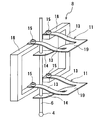
- FIG. 2 is a perspective view showing details of the spring mechanism 8.
- the spring mechanism 8 includes E-shaped plate springs 11, 11, bolts 15, and fixed frames 18, 18.
- the support bar 6 is elastically held by the E-shaped plate springs 11 and 11.
- the E-shaped leaf springs 11 and 11 are arranged in parallel to each other on the axis of the support bar 6.
- the free ends of the side spring pieces 13 and 13 in the E-shaped leaf spring 11 are fixed to the fixed frames 18 and 18 by bolts 15 and 15, and the support bar 6 is fixed to the free ends of the central spring piece 14. ing.
- the fixed frames 18 and 18 are respectively supported by support bases 12 and 12 shown in FIG.
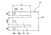
- FIG. 3 is a plan view of the E-shaped leaf spring shown in FIG.
- the E-shaped spring 11 includes a pair of rectangular side spring pieces 13, 13 and a rectangular central spring piece 14 positioned between the side spring pieces 13, 13.
- the side spring pieces 13 and 13 and the central spring piece 14 are composed of a connecting portion 19 that connects at one end.
- the pair of side spring pieces 13 and 13 are formed in the same shape and the same dimensions, and the length from the connecting portion 19 is set to L and the width is set to W.
- the central spring piece 14 is set to have a length L from the connecting portion 19 and a width of 2W.
- the connecting portion 19, the side spring pieces 13, and the central spring piece 14 have the same thickness.
- the spring constant of the pair of side spring pieces 13, 13 is the same as the spring constant of the central spring piece 14.
- Each E-shaped spring 11 configured as shown in FIG. 3 is arranged at the position shown in FIG. That is, the bolts 15 and 15 are inserted into holes 13 a and 13 a formed at the free ends of the pair of side spring pieces 13 and 13, and the free ends of the pair of side spring pieces 13 and 13 are attached to the fixed frames 18 and 18. Fix it. Then, the support bar 6 is inserted into the hole 14 a formed at the free end of the central spring piece 14, and the support bar 6 is fixed to the free end of the central spring piece 14. That is, the free ends of the side spring pieces 13, 13 are fixed to the fixed frame 18, and the free ends of the central spring pieces 14 are fixed to the support bar 6.
- the side spring pieces 13 and 13 are caused to function as a fixed part spring piece whose one end is fixed to the fixed part, and the central spring piece 14 is functioned as a moving part spring piece whose one end supports the support rod 6 so as to be movable.
- Two or more E-shaped springs 11 are arranged in parallel on the axis of the support bar 6 (FIG. 2 shows an example in which two E-shaped springs 11 are arranged).
- FIG. 4 is a schematic diagram showing a state in which the E-shaped springs 11 and 11 are deformed when a load is applied to the support rod 6 in the axial direction.
- the side spring piece 13 and the central spring piece 14 are deformed, and the end portion of the connecting portion 19 moves circularly around a fixed point P ⁇ b> 1 where the side spring piece 13 is fixed to the fixed frame 18.
- Perform M1 The motion point P2 at which the support bar 6 is fixed to the central spring piece 14 performs a circular motion M2 around the end of the connecting portion 19.
- the point P2 is located below in the vertical direction of the point P1. That is, the circular motion cancels out by the side spring pieces 13 and 13 as the fixed part spring pieces and the central part spring piece 14 as the moving part spring piece, and the support bar 6 and the probe 4 move linearly only in the vertical direction.
- the electromagnetic force generator 20 includes a coil 22 connected to the support rod 6 and a magnetic field generator 24 that generates a magnetic field.
- the coil 22 has a cylindrical shape, and a disk member 23 is attached to the lower end thereof. The central portion of the disk member 23 is fixed to the support rod 6, and the coil 22, the support rod 6, and the probe 4 can be moved linearly in the vertical direction integrally.
- the magnetic field generator 24 includes an annular permanent magnet 26, a cylindrical yoke 27 fixed to the inner peripheral surface of the permanent magnet 26, and a cylindrical yoke 28 fixed to the outer peripheral surface of the permanent magnet 26. Yes.
- the permanent magnet 26, the yoke 27, and the yoke 28 are disposed concentrically.
- the coil 22 is disposed between the yoke 27 and the yoke 28.
- a magnetic field is formed between the yoke 27 and the yoke 28, and the coil 22 is placed in the magnetic field.
- a current is passed through the coil 22
- an electromagnetic force that moves the coil 22 in the vertical direction is generated.
- This electromagnetic force applies a load to the support rod 6 connected to the coil 22. Accordingly, the support bar 6 and the probe 4 move (displace) in the vertical direction under the load from the electromagnetic force generator 20.
- This load can be controlled by a current flowing through the coil 22.
- the surface force measuring apparatus further includes a coarse movement stage (XYZ stage) 32 that moves the DUT 1 in the horizontal direction and the vertical direction, and a fine movement stage 30 for accurately positioning the DUT 1.
- the fine movement stage 30 is configured to move the DUT 1 only in the vertical direction.
- the fine movement stage 30 is disposed on the coarse movement stage 32, and the DUT 1 is placed on the fine movement stage 30.
- the fine movement stage 30 and the DUT 1 are moved together by the coarse movement stage 32 in the horizontal direction and the vertical direction. Note that the coarse movement stage 32 may be disposed on the fine movement stage 30 and the DUT 1 may be placed on the coarse movement stage 32.
- the coarse movement stage 32 it is preferable to use a combination of a ball screw mechanism as its actuator, and as the fine movement stage 30, it is preferable to use a piezo element as its actuator.
- the coarse movement stage 32 is a first positioning mechanism that performs rough positioning of the DUT 1
- the fine movement stage 30 is a second positioning mechanism that performs more precise positioning than the coarse movement stage 32.
- the probe 4, the support rod 6, the spring mechanism 8, the support bases 12 and 12, the electromagnetic force generator 20, the fine movement stage 30, and the coarse movement stage 32 are disposed in the vacuum chamber 40.
- the vacuum chamber 40 is connected to a vacuum device (not shown), and a vacuum is formed in the vacuum chamber 40 by driving the vacuum device. Thereby, the surface force can be measured in an environment that is not affected by the surrounding atmosphere, and stable measurement is ensured.
- the vacuum chamber 40 is disposed on the vibration isolation table 42, and the vibration of the vacuum chamber 40 is removed by the vibration isolation table 42.
- a temperature control device 46 having a circulation pipe 44 is disposed under the vibration isolation table 42, and cooling water is supplied to the circulation pipe 44 of the temperature control device 46 from a cooling water supply source (not shown). Yes.
- a cooling water supply source not shown
- the temperature control device 46 stabilizes the temperatures of the devices (for example, the probe 4, the support rod 6, the spring mechanism 8, the electromagnetic force generator 20, etc.) arranged in the vacuum chamber 40, and the thermal expansion thereof. Is prevented.
- the vibration isolation table 42 is disposed under the vacuum chamber 40, but the vibration isolation table 42 is disposed in the vacuum chamber 40, and the coarse motion stage 32 and the support tables 12, 12 are disposed on the vibration isolation table. It may be arranged on 42.
- an operation control device 50 is disposed outside the vacuum chamber 40.
- the operation control device 50 is a device that controls operations of the electromagnetic force generator 20, the fine movement stage 30, and the coarse movement stage 32.
- the surface force acting between the DUT 1 and the probe 4 is determined by measuring a force required to pull the probe 4 in contact with the DUT 1 from the DUT 1. . Specifically, the surface force is measured as follows. First, the device under test 1 is moved toward the probe 4 until the probe 4 is attracted to the device under test 1 by surface force. Next, in a state where the probe 4 is attracted to the device under test 1, the current flowing through the coil 22 is gradually increased to pull the probe 4 away from the device under test 1. Then, the current value flowing through the coil 22 at the moment when the probe 4 is separated from the device under test 1 is converted into a load (electromagnetic force) generated by the electromagnetic force generator 20, and this converted load is converted into the device under test 1. The surface force acting between the probe 4 and the probe 4 is determined. The value of the current flowing through the coil 22 is converted into a load (electromagnetic force) generated by the electromagnetic force generator 20 using a predetermined relational expression stored in advance in the control device 50.
- FIG. 5 is a graph showing changes in the positions of the probe 4 and the DUT 1 when the surface force is measured.
- the vertical axis indicates the position of the probe 4 and the DUT 1 in the vertical direction
- the horizontal axis indicates time.
- a thick line indicates the movement locus of the probe 4
- a thin line indicates the movement locus of the DUT 1.
- the fine movement stage 30 is driven to gradually move the DUT 1 toward the probe 4 (t2 ⁇ t3).
- a surface force acts between the DUT 1 and the probe 4.
- the probe 4 descends against the reaction force of the E-shaped plate springs 11 and 11, and finally the probe 4 comes into contact with the device under test 1 (t3).
- the probe 4 is displaced downward from its initial position Pini (a position where the displacement of the probe 4 is zero).
- the force with which the DUT 1 attracts the probe 4 is called adsorption force.
- This attraction force can be obtained by multiplying the displacement of the probe 4 from the initial position Pini (indicated by symbol D1 in FIG. 5) by the spring constant of the E-shaped leaf springs 11 and 11.
- the surface force is determined from the load (force) necessary for pulling the probe 4 away from the object 1 to be measured.
- the reaction force of the E-shaped springs 11 and 11 acts in the direction of pulling the probe 4 away from the object 1 to be measured.
- an error may occur between the measured value of the surface force and the actual surface force. Therefore, in order to reduce this error as much as possible, the probe 4 and the device under test 1 are raised by the fine movement stage 30 until the probe 4 returns to its initial position Pini while the probe 4 and the device under test 1 are in contact with each other. (T4 ⁇ t5).
- the current flowing through the coil 22 is gradually increased, and the upward load acting on the support rod 6 is increased.
- This upward load acts on the probe 4 as a force for pulling the probe 4 away from the object 1 to be measured.
- the probe 4 moves away from the DUT 1 (t6).
- the motion control device 50 acquires the value of the current flowing through the coil 22 at the moment when the probe 4 is separated from the device under test 1 and determines the force for pulling the probe 4 away from the device under test 1 based on this current value. .
- Such a force for pulling the probe 4 away from the DUT 1 is called an adhesion force. This adhesion force corresponds to the surface force.
- the surface force measuring device can accurately measure the surface force acting between the DUT 1 and the probe 4.
- the motion control device 50 can detect from the displacement of the probe 4 measured by the displacement meter 9 that the probe 4 has been attracted to the device under test 1 and that the probe 4 has been pulled away from the device under test 1. it can. That is, the motion control device 50 adsorbs the probe 4 to the DUT 1 based on the time point when the downward displacement of the probe 4 (indicated by reference numeral D1 in FIG. 5) exceeds a predetermined first threshold value. The probe 4 is moved away from the DUT 1 based on the time when the upward displacement of the probe 4 (indicated by reference numeral D2 in FIG. 5) exceeds a predetermined second threshold value. Determine the time.
- the motion control device 50 converts the current value into a surface force using a predetermined relational expression.
- This relational expression is acquired in advance as follows. A plurality of sample weights having different weights are prepared, and one of these sample weights is attached to the support bar 6. In this state, a current is passed through the coil 22, and the current is gradually increased until the sample weight is lifted by the electromagnetic force generator 20. The current value at the time when the sample weight is lifted up to the height (initial position) of the support rod 6 before the sample weight is attached is obtained, and this current value is related to the weight of the sample weight.
- the correlation between the current value and the weight is obtained.
- the weight of the sample weight corresponds to the surface force acting between the probe 4 and the DUT 1. Therefore, the correlation between the current value and the weight corresponds to the correlation between the current value and the surface force.
- the correlation between the current value and the surface force is expressed as a linear function expression.
- the linear function formula obtained in this way is stored in advance in the motion control device 50.
- the motion control device 50 can determine the surface force by inputting the current value at the moment when the probe 4 is separated from the DUT 1 to the linear function equation.
- the present invention is applicable to a method and an apparatus for measuring a force acting between two material surfaces.
Landscapes
- Physics & Mathematics (AREA)
- Health & Medical Sciences (AREA)
- General Health & Medical Sciences (AREA)
- General Physics & Mathematics (AREA)
- Nuclear Medicine, Radiotherapy & Molecular Imaging (AREA)
- Radiology & Medical Imaging (AREA)
- Length Measuring Devices With Unspecified Measuring Means (AREA)
- Force Measurement Appropriate To Specific Purposes (AREA)
- Investigating Strength Of Materials By Application Of Mechanical Stress (AREA)
Abstract
本発明は、2つの物質表面間に作用する力(以下、表面力と呼ぶ)を測定する方法および装置を提供する。表面力測定方法は、プローブ(4)が被測定物(1)に吸着されるまで被測定物(1)をプローブ(4)に向かって移動させ、その後、電磁力発生器(20)に供給する電流を徐々に増加させながら、電磁力発生器(20)によって、プローブ(4)が被測定物(1)から離れる方向に支持部材(6)に荷重を加え、プローブ(4)が被測定物(1)から離れたときに電磁力発生器(20)に供給されている電流の値を取得し、電流値を、プローブ(4)と被測定物(1)との間に作用する表面力に変換する。
Description
本発明は、2つの物質表面間に作用する力(以下、表面力と呼ぶ)を測定する方法および装置に関するものである。
一般的に、表面力を測定する方法として、原子間力顕微鏡(AFM:Atomic Force Microscope)を用いたフォースカーブ測定や表面力測定装置(例えば特許文献1参照)を用いた測定が知られている。カンチレバー(片持ちばね)の先端に取り付けられたプローブ(探針)を被測定物(試料)に接近させると、被測定物とプローブとの間に作用する表面力によりプローブが被測定物に引き寄せられ、プローブが被測定物に接触する。この状態から、プローブを被測定物から引き離そうとするとき、表面力によってプローブが被測定物に接触した状態が続き、ある位置でプローブが被測定物から離れる。このときのカンチレバーのたわみ量(すなわちプローブの変位)とカンチレバーのばね定数とを乗算することで表面力が算出される。
カンチレバーを用いて表面力を測定する場合、表面力の測定可能な範囲はカンチレバーのばね定数に依存する。測定する表面力に対してばね定数が小さすぎる場合にはカンチレバーのたわみ量が大きくなる。カンチレバーがたわむときのプローブの軌道は、カンチレバーが取り付けられている支点を中心とした円軌道であるため、プローブの変位方向は表面力の作用方向と一致しない。したがって、プローブの変位方向と表面力の作用方向が一致しないことによって生ずる測定値と実際の表面力との誤差が無視できなくなる。また、測定する表面力に対してばね定数が大きすぎる場合にはカンチレバーのたわみ量が小さくなるため、プローブの変位測定の誤差が大きくなる。
以上の理由から、カンチレバーを用いて表面力を正確に測定するためには、表面力の測定範囲に適したばね定数を有するカンチレバーを選定しなければならないが、測定条件ごとにカンチレバーを交換することは手間と時間がかかってしまう。しかし、このような不都合を課題として認識することはなされておらず、示唆もされていない。
以上の理由から、カンチレバーを用いて表面力を正確に測定するためには、表面力の測定範囲に適したばね定数を有するカンチレバーを選定しなければならないが、測定条件ごとにカンチレバーを交換することは手間と時間がかかってしまう。しかし、このような不都合を課題として認識することはなされておらず、示唆もされていない。
本発明は、上述した不都合を解決するためになされたもので、表面力を広い範囲で正確に測定することができる表面力測定方法および表面力測定装置を提供することを目的とする。
上記目的を達成するために、支持部材と、前記支持部材に固定されたプローブと、前記支持部材を弾性的に保持し、該支持部材に直線運動のみを許容するばね機構と、前記支持部材に荷重を加えるための電磁力を発生させる電磁力発生器とを備えた装置を用いた表面力測定方法であって、前記プローブが被測定物に吸着されるまで前記被測定物を前記プローブに向かって移動させ、その後、前記電磁力発生器に供給する電流を徐々に増加させながら、前記電磁力発生器によって、前記プローブが前記被測定物から離れる方向に前記支持部材に荷重を加え、前記プローブが前記被測定物から離れたときに前記電磁力発生器に供給されている電流の値を取得し、前記電流値を、前記プローブと前記被測定物との間に作用する表面力に変換することを特徴とする。
本発明の好ましい態様は、前記プローブが前記被測定物に吸着された後に、前記プローブと前記被測定物とが接触したまま前記プローブがその初期位置に戻るまで前記プローブおよび前記被測定物を移動させ、その後、前記電磁力発生器に供給する電流を徐々に増加させながら、前記電磁力発生器によって、前記プローブが前記被測定物から離れる方向に前記支持部材に荷重を加えることを特徴とする。
本発明の好ましい態様は、前記被測定物、前記プローブ、前記支持部材、前記ばね機構、および前記電磁力発生器が配置される空間を真空にすることを特徴とする。
本発明の好ましい態様は、前記被測定物、前記プローブ、前記支持部材、前記ばね機構、および前記電磁力発生器の温度を制御することを特徴とする。
本発明の好ましい態様は、前記電流値と前記表面力との相関を表す所定の関係式を用いて、前記電流値を前記表面力に変換することを特徴とする。
本発明の好ましい態様は、前記被測定物、前記プローブ、前記支持部材、前記ばね機構、および前記電磁力発生器が配置される空間を真空にすることを特徴とする。
本発明の好ましい態様は、前記被測定物、前記プローブ、前記支持部材、前記ばね機構、および前記電磁力発生器の温度を制御することを特徴とする。
本発明の好ましい態様は、前記電流値と前記表面力との相関を表す所定の関係式を用いて、前記電流値を前記表面力に変換することを特徴とする。
本発明の他の態様は、支持部材と、前記支持部材に固定されたプローブと、前記支持部材を弾性的に保持し、該支持部材に直線運動のみを許容するばね機構と、前記支持部材に荷重を加えるための電磁力を発生させる電磁力発生器と、前記プローブの変位を測定する変位測定器と、被測定物の位置決めを行う第1位置決め機構と、前記第1位置決め機構よりも精密に前記被測定物の位置決めを行う第2位置決め機構と、前記電磁力発生器、前記第1位置決め機構、および前記第2位置決め機構の動作を制御する動作制御装置とを備え、前記動作制御装置は、前記第2位置決め機構により、前記プローブが前記被測定物に吸着されるまで前記被測定物を前記プローブに向かって移動させ、その後、前記電磁力発生器に供給する電流を徐々に増加させながら、前記電磁力発生器によって、前記プローブが前記被測定物から離れる方向に前記支持部材に荷重を加え、前記プローブが前記被測定物から離れたときに前記電磁力発生器に供給されている電流の値を取得し、前記電流値を、前記プローブと前記被測定物との間に作用する表面力に変換するように構成されていることを特徴とする表面力測定装置である。
本発明の好ましい態様は、前記動作制御装置は、前記プローブが前記被測定物に吸着された後に、前記第2位置決め機構により、前記プローブと前記被測定物とが接触したまま前記プローブがその初期位置に戻るまで前記プローブおよび前記被測定物を移動させることを特徴とする。
本発明の好ましい態様は、前記被測定物、前記プローブ、前記支持部材、前記ばね機構、前記電磁力発生器、前記変位測定器、前記第1位置決め機構、および前記第2位置決め機構が内部に配置される真空チャンバをさらに備えたことを特徴とする。
本発明の好ましい態様は、前記被測定物、前記プローブ、前記支持部材、前記ばね機構、前記電磁力発生器、前記変位測定器、前記第1位置決め機構、および前記第2位置決め機構の温度を制御する温度制御装置をさらに備えたことを特徴とする。
本発明の好ましい態様は、前記動作制御装置は、前記電流値と前記表面力との相関を表す所定の関係式を記憶しており、前記所定の関係式を用いて前記電流値を前記表面力に変換することを特徴とする。
本発明によれば、表面力は、プローブが被測定物から離れた瞬間の電流値を基に決定される。表面力を算出するためにばね定数は不要であり、ばね定数に依存せずに表面力を測定することができる。したがって、広い範囲での表面力の測定が可能となる。さらに、ばね機構は支持部材の直線運動のみを許容するので、プローブの変位方向は表面力の作用方向に一致する。したがって、表面力を正確に測定することができる。
以下、本発明の実施形態について図面を参照して説明する。
図1は、本発明の一実施形態に係る表面力測定装置の全体構造を示す模式図である。図1に示すように、表面力測定装置は、プローブ(探針)4と、プローブ4を支持する支持棒(支持部材)6と、支持棒6を弾性的に保持するばね機構8と、支持棒6に鉛直方向の荷重を加えるための電磁力を発生させる電磁力発生器20と、プローブ4の変位を計測する変位計9とを備えている。支持棒6は、鉛直方向に延びており、その先端(下端)にプローブ4が固定されている。
図1は、本発明の一実施形態に係る表面力測定装置の全体構造を示す模式図である。図1に示すように、表面力測定装置は、プローブ(探針)4と、プローブ4を支持する支持棒(支持部材)6と、支持棒6を弾性的に保持するばね機構8と、支持棒6に鉛直方向の荷重を加えるための電磁力を発生させる電磁力発生器20と、プローブ4の変位を計測する変位計9とを備えている。支持棒6は、鉛直方向に延びており、その先端(下端)にプローブ4が固定されている。
ばね機構8は、2つの支持台12,12によって支持されている。変位計9は、これら2つの支持台12,12のうちの一方に固定されている。支持棒6には測定ターゲット10が固定されており、この測定ターゲット10は支持棒6およびプローブ4と一体に鉛直方向に上下動する。変位計9は、この測定ターゲット10の鉛直方向の変位からプローブ4の鉛直方向の変位を測定する。変位計9としては、非接触式の変位センサが好ましく用いられる。
図2は、ばね機構8の詳細を示す斜視図である。図2に示すように、ばね機構8は、E字型板ばね11,11と、ボルト15と、固定フレーム18,18とを備えている。支持棒6はE字型板ばね11,11に弾性的に保持されている。E字型板ばね11,11は、支持棒6の軸上に互いに平行に配置されている。E字型板ばね11における側部ばね片13,13の自由端はボルト15,15により固定フレーム18,18に固定されており、中央部ばね片14の自由端には支持棒6が固定されている。固定フレーム18,18は図1に示す支持台12,12にそれぞれ支持されている。
図3は、図2に示すE字型板ばねの平面図である。図3に示すように、E字型ばね11は、一対の矩形状の側部ばね片13,13と、これら側部ばね片13,13の中間に位置する矩形状の中央部ばね片14と、側部ばね片13,13と中央部ばね片14とを一端部で連結する連結部19とから構成されている。一対の側部ばね片13,13は、同一形状および同一寸法に形成されており、連結部19からの長さがL、幅がWに設定されている。中央部ばね片14は、連結部19からの長さがL、幅が2Wに設定されている。連結部19、側部ばね片13、および中央部ばね片14は、同一の厚さを有している。これにより、一対の側部ばね片13,13を合わせたばね定数が中央部ばね片14のばね定数と同一になっている。
図3に示すように構成された各E字型ばね11は図2に示す位置に配置される。すなわち、一対の側部ばね片13,13の自由端に形成された孔13a,13aにボルト15,15を挿入し、一対の側部ばね片13,13の自由端を固定フレーム18,18に固定する。そして、中央部ばね片14の自由端に形成された孔14aに支持棒6を挿入し、中央部ばね片14の自由端に支持棒6を固定する。すなわち、側部ばね片13,13の自由端を固定フレーム18に固定し、中央部ばね片14の自由端を支持棒6に固定する。これにより、側部ばね片13,13を一端が固定部に固定された固定部ばね片、中央部ばね片14を一端が支持棒6を運動可能に支持する運動部ばね片として機能させる。そして、E字型ばね11は支持棒6の軸上に平行に2枚以上配置される(図2ではE字型ばね11を2枚配置した例を示している)。
図2に示す構成において、支持棒6にその軸方向に荷重を加えたとき、固定部ばね片としての側部ばね片13,13および運動部ばね片としての中央部ばね片14がともに変形する。この変形とともに、平行に配置された一対のE字型ばね11における、固定部ばね片としての側部ばね片13,13および運動部ばね片としての中央部ばね片14で円運動が打ち消し合い、支持棒6はその軸方向に直線運動することのみが許容される。結果として、プローブ4は被測定物1に対し、常に同じ向きを保持し、プローブ4は鉛直方向に沿って直線的に移動する。
図4は支持棒6にその軸方向に荷重を加えたとき、E字型ばね11,11が変形した状態を示す模式図である。図4に示すように、側部ばね片13および中央部ばね片14は変形し、連結部19の端部は、側部ばね片13を固定フレーム18に固定した固定点P1を中心として円運動M1を行なう。また支持棒6を中央部ばね片14に固定した運動点P2は、連結部19の端部を中心として円運動M2を行なう。この結果、点P2は点P1の鉛直方向において下方に位置する。即ち、固定部ばね片としての側部ばね片13,13および運動部ばね片としての中央部ばね片14で円運動が打ち消し合い、支持棒6およびプローブ4は鉛直方向にのみ直線移動する。
図1に示すように、電磁力発生器20は、支持棒6に連結されたコイル22と、磁界を発生させる磁界発生部24とを備えている。コイル22は円筒形状を有しており、その下端には円板部材23が取り付けられている。円板部材23の中心部は支持棒6に固定されており、これにより、コイル22と支持棒6とプローブ4とは一体に鉛直方向に直線的に移動可能となっている。磁界発生部24は、環状の永久磁石26と、永久磁石26の内周面に固定された円筒状のヨーク27と、永久磁石26の外周面に固定された円筒状のヨーク28とを備えている。永久磁石26、ヨーク27、およびヨーク28は同心状に配置されている。コイル22はヨーク27とヨーク28との間に配置されている。
ヨーク27とヨーク28との間には磁界が形成されており、コイル22は磁界の中に置かれている。この状態で、コイル22に電流を流すとコイル22を鉛直方向に移動させる電磁力が発生する。この電磁力はコイル22に連結されている支持棒6に荷重を与える。したがって、支持棒6およびプローブ4は、電磁力発生器20からの荷重を受けて鉛直方向に移動(変位)する。この荷重はコイル22に流す電流によって制御することが可能である。
表面力測定装置は、被測定物1を水平方向および鉛直方向に移動させる粗動ステージ(XYZステージ)32と、被測定物1の正確な位置決めを行うための微動ステージ30とをさらに備えている。微動ステージ30は、被測定物1を鉛直方向にのみ移動させるように構成されている。微動ステージ30は粗動ステージ32上に配置されており、被測定物1は微動ステージ30の上に載置される。微動ステージ30および被測定物1は、一体に水平方向および鉛直方向に粗動ステージ32によって移動される。なお、微動ステージ30の上に粗動ステージ32を配置し、粗動ステージ32の上に被測定物1を載置してもよい。
粗動ステージ32としては、そのアクチュエータとしてボールねじ機構の組み合わせを用いることが好ましく、微動ステージ30としては、そのアクチュエータとしてピエゾ素子を用いることが好ましい。粗動ステージ32は、被測定物1の大まかな位置決めを行う第1位置決め機構であり、微動ステージ30は粗動ステージ32よりも精密な位置決めを行う第2位置決め機構である。
プローブ4、支持棒6、ばね機構8、支持台12,12、電磁力発生器20、微動ステージ30、および粗動ステージ32は真空チャンバ40内に配置されている。真空チャンバ40は図示しない真空装置に接続されており、真空装置を駆動することで真空チャンバ40内に真空が形成される。これにより、周囲雰囲気の影響を受けない環境下で表面力を測定することができ、安定した測定が確保される。真空チャンバ40は除振台42の上に配置されており、除振台42によって真空チャンバ40の振動が除去される。
除振台42の下には、循環配管44を有する温度制御装置46が配置されており、図示しない冷却水供給源から冷却水が温度制御装置46の循環配管44に供給されるようになっている。冷却水が循環配管44内に供給されることにより、真空チャンバ40の内部空間が所定の温度に保たれる。温度制御装置46によって、真空チャンバ40内に配置された機器(例えばプローブ4、支持棒6、ばね機構8、電磁力発生器20など)および被測定物1の温度が安定し、これらの熱膨張が防止される。なお、図1では除振台42は真空チャンバ40の下に配置されているが、除振台42を真空チャンバ40の中に配置し、粗動ステージ32および支持台12,12を除振台42の上に配置してもよい。
図1に示すように、真空チャンバ40の外部には動作制御装置50が配置されている。動作制御装置50は、電磁力発生器20、微動ステージ30、および粗動ステージ32の動作を制御する装置である。
被測定物1とプローブ4との間に作用する表面力は、被測定物1に接触している状態のプローブ4を被測定物1から引き離すために必要な力を測定することで決定される。具体的には次のようにして表面力が測定される。まず、プローブ4が被測定物1に表面力によって吸着されるまで、被測定物1をプローブ4に向かって移動させる。次に、プローブ4が被測定物1に吸着された状態で、コイル22に流す電流を徐々に増加させてプローブ4を被測定物1から引き離す。そして、プローブ4が被測定物1から引き離された瞬間のコイル22に流れる電流値を、電磁力発生器20が発生した荷重(電磁力)に変換し、この変換された荷重を被測定物1とプローブ4との間に作用する表面力として決定する。コイル22に流れる電流値は、制御装置50に予め記憶されている所定の関係式を用いて電磁力発生器20が発生した荷重(電磁力)に変換される。
図5は、表面力を測定するときのプローブ4および被測定物1の位置の変化を示すグラフである。図5において、縦軸はプローブ4および被測定物1の鉛直方向の位置を示し、横軸は時間を示す。太線はプローブ4の移動軌跡を示し、細線は被測定物1の移動軌跡を示す。まず、粗動ステージ32が駆動されて、被測定物1がプローブ4に接触するまで被測定物1をプローブ4に向かって移動させる(t0→t1)。被測定物1がプローブ4に接触した後、粗動ステージ32によって被測定物1を反対方向に移動させてプローブ4から被測定物1を離間させる(t1→t2)。被測定物1がプローブ4に接触した時点、および被測定物1がプローブ4から離れた時点は、変位計9によって測定されるプローブ4の変位から決定することができる。
次に、微動ステージ30が駆動されて被測定物1をプローブ4に向かって徐々に移動させる(t2→t3)。被測定物1がプローブ4に接近するにつれて、被測定物1とプローブ4との間に表面力が作用する。プローブ4は、E字型板ばね11,11の反力に抗って下降し、ついにはプローブ4は被測定物1に接触する(t3)。その結果、プローブ4はその初期位置Pini(プローブ4の変位がゼロの位置)から下方に変位する。被測定物1がプローブ4を引き付ける力は吸着力と呼ばれる。この吸着力はプローブ4の初期位置Piniからの変位(図5にて記号D1で示す)にE字型板ばね11,11のばね定数を掛けることによって求めることができる。
本実施形態では、プローブ4を被測定物1から引き離すために必要な荷重(力)から表面力を決定する。しかしながら、プローブ4がその初期位置Piniから下方に変位すると、E字型ばね11,11の反力がプローブ4を被測定物1から引き離す方向に作用する。このため、プローブ4が下方向に変位したまま表面力の測定を開始すると、表面力の測定値と実際の表面力との間に誤差が生じることがある。そこで、この誤差を限りなく小さくするために、プローブ4および被測定物1が互いに接触した状態で、プローブ4がその初期位置Piniに戻るまでプローブ4および被測定物1を微動ステージ30により上昇させる(t4→t5)。プローブ4が初期位置Piniにあるとき、E字型ばね11,11のたわみ量は実質的にゼロであるので、E字型ばね11,11内のストレスがゼロとなる。この状態で、表面力の測定が開始される。すなわち、コイル22への電流供給が開始される。
コイル22に流す電流を徐々に増大させ、支持棒6に作用する上向きの荷重を増大させる。この上向きの荷重は、プローブ4を被測定物1から引き離す力としてプローブ4に作用する。上向きの荷重が表面力と等しくなったとき、プローブ4は被測定物1から離れる(t6)。動作制御装置50は、プローブ4が被測定物1から離れた瞬間にコイル22に流れている電流の値を取得し、この電流値に基づいてプローブ4を被測定物1から引き離す力を決定する。このようなプローブ4を被測定物1から引き離す力は凝着力と呼ばれる。この凝着力は表面力に相当する。
プローブ4は、被測定物1の真上に位置しているので、表面力は鉛直方向に発生する。E字型板ばね11,11は支持棒6の鉛直方向のみの移動を許容するので、支持棒6に固定されたプローブ4は鉛直方向に移動する。すなわち、プローブ4を被測定物1から引き離す力の作用方向は、プローブ4と被測定物1との間に作用する表面力の方向と一致する。したがって、表面力測定装置は、被測定物1とプローブ4との間に作用する表面力を正確に計測することができる。
動作制御装置50は、プローブ4が被測定物1に吸着されたこと、およびプローブ4が被測定物1から引き離されたことを、変位計9によって測定されるプローブ4の変位から検出することができる。すなわち、動作制御装置50は、プローブ4の下方への変位(図5に符号D1で示す)が所定の第1のしきい値を超えた時点に基づいて、プローブ4が被測定物1に吸着された時点を決定し、プローブ4の上方への変位(図5に符号D2で示す)が所定の第2のしきい値を超えた時点に基づいて、プローブ4が被測定物1から離れた時点を決定する。
コイル22に流れる電流の値を表面力に変換する方法の一例について説明する。動作制御装置50は、所定の関係式を用いて電流値を表面力に変換する。この関係式は次のようにして予め取得される。重さの異なる複数のサンプルおもりを用意し、これらのサンプルおもりのうちの1つを支持棒6に取り付ける。この状態でコイル22に電流を流し、さらにサンプルおもりが電磁力発生器20によって持ち上げられるまで電流を少しずつ増加させる。サンプルおもりが取り付けられる前の支持棒6の高さ(初期位置)まで、サンプルおもりが持ち上げられた時点の電流値を取得し、この電流値をサンプルおもりの重さに関連付ける。同様の作業をすべてのサンプルおもりについて実行することによって、電流値と重さとの相関が取得される。サンプルおもりの重さは、プローブ4と被測定物1との間に作用する表面力に相当する。したがって、電流値と重さとの相関は、電流値と表面力との相関に相当する。この電流値と表面力との相関は、一次関数式として表される。このようにして得られた一次関数式は動作制御装置50に予め記憶される。動作制御装置50は、プローブ4が被測定物1から離れた瞬間の電流値を一次関数式に入力することによって、表面力を決定することができる。
これまで本発明の実施形態について説明したが、本発明は上述の実施形態に限定されず、その技術思想の範囲内において、種々の異なる形態で実施されてよいことは勿論である。
本発明は、2つの物質表面間に作用する力を測定する方法および装置に利用可能である。
1 被測定物
4 プローブ
6 支持棒
8 ばね機構
9 変位計
10 測定ターゲット
11 E字型板ばね
12 支持台
13 側部ばね片
14 中央部ばね片
15 ボルト
18 固定フレーム
19 連結部
20 電磁力発生器
22 コイル
23 円板部材
24 磁界発生部
26 永久磁石
27,28 ヨーク
30 微動ステージ
32 粗動ステージ
40 真空チャンバ
42 除振台
44 循環配管
46 温度調整装置
50 動作制御装置
4 プローブ
6 支持棒
8 ばね機構
9 変位計
10 測定ターゲット
11 E字型板ばね
12 支持台
13 側部ばね片
14 中央部ばね片
15 ボルト
18 固定フレーム
19 連結部
20 電磁力発生器
22 コイル
23 円板部材
24 磁界発生部
26 永久磁石
27,28 ヨーク
30 微動ステージ
32 粗動ステージ
40 真空チャンバ
42 除振台
44 循環配管
46 温度調整装置
50 動作制御装置
Claims (10)
- 支持部材と、
前記支持部材に固定されたプローブと、
前記支持部材を弾性的に保持し、該支持部材に直線運動のみを許容するばね機構と、
前記支持部材に荷重を加えるための電磁力を発生させる電磁力発生器とを備えた装置を用いた表面力測定方法であって、
前記プローブが被測定物に吸着されるまで前記被測定物を前記プローブに向かって移動させ、
その後、前記電磁力発生器に供給する電流を徐々に増加させながら、前記電磁力発生器によって、前記プローブが前記被測定物から離れる方向に前記支持部材に荷重を加え、
前記プローブが前記被測定物から離れたときに前記電磁力発生器に供給されている電流の値を取得し、
前記電流値を、前記プローブと前記被測定物との間に作用する表面力に変換することを特徴とする表面力測定方法。 - 前記プローブが前記被測定物に吸着された後に、前記プローブと前記被測定物とが接触したまま前記プローブがその初期位置に戻るまで前記プローブおよび前記被測定物を移動させ、
その後、前記電磁力発生器に供給する電流を徐々に増加させながら、前記電磁力発生器によって、前記プローブが前記被測定物から離れる方向に前記支持部材に荷重を加えることを特徴とする請求項1に記載の表面力測定方法。 - 前記被測定物、前記プローブ、前記支持部材、前記ばね機構、および前記電磁力発生器が配置される空間を真空にすることを特徴とする請求項1または2に記載の表面力測定方法。
- 前記被測定物、前記プローブ、前記支持部材、前記ばね機構、および前記電磁力発生器の温度を制御することを特徴とする請求項1乃至3のいずれか一項に記載の表面力測定方法。
- 前記電流値と前記表面力との相関を表す所定の関係式を用いて、前記電流値を前記表面力に変換することを特徴とする請求項1乃至4のいずれか一項に記載の表面力測定方法。
- 支持部材と、
前記支持部材に固定されたプローブと、
前記支持部材を弾性的に保持し、該支持部材に直線運動のみを許容するばね機構と、
前記支持部材に荷重を加えるための電磁力を発生させる電磁力発生器と、
前記プローブの変位を測定する変位測定器と、
被測定物の位置決めを行う第1位置決め機構と、
前記第1位置決め機構よりも精密に前記被測定物の位置決めを行う第2位置決め機構と、
前記電磁力発生器、前記第1位置決め機構、および前記第2位置決め機構の動作を制御する動作制御装置とを備え、
前記動作制御装置は、
前記第2位置決め機構により、前記プローブが前記被測定物に吸着されるまで前記被測定物を前記プローブに向かって移動させ、
その後、前記電磁力発生器に供給する電流を徐々に増加させながら、前記電磁力発生器によって、前記プローブが前記被測定物から離れる方向に前記支持部材に荷重を加え、
前記プローブが前記被測定物から離れたときに前記電磁力発生器に供給されている電流の値を取得し、
前記電流値を、前記プローブと前記被測定物との間に作用する表面力に変換するように構成されていることを特徴とする表面力測定装置。 - 前記動作制御装置は、前記プローブが前記被測定物に吸着された後に、前記第2位置決め機構により、前記プローブと前記被測定物とが接触したまま前記プローブがその初期位置に戻るまで前記プローブおよび前記被測定物を移動させることを特徴とする請求項6に記載の表面力測定装置。
- 前記被測定物、前記プローブ、前記支持部材、前記ばね機構、前記電磁力発生器、前記変位測定器、前記第1位置決め機構、および前記第2位置決め機構が内部に配置される真空チャンバをさらに備えたことを特徴とする請求項6または7に記載の表面力測定装置。
- 前記被測定物、前記プローブ、前記支持部材、前記ばね機構、前記電磁力発生器、前記変位測定器、前記第1位置決め機構、および前記第2位置決め機構の温度を制御する温度制御装置をさらに備えたことを特徴とする請求項6乃至8のいずれか一項に記載の表面力測定装置。
- 前記動作制御装置は、前記電流値と前記表面力との相関を表す所定の関係式を記憶しており、前記所定の関係式を用いて前記電流値を前記表面力に変換することを特徴とする請求項6乃至9のいずれか一項に記載の表面力測定装置。
Priority Applications (2)
| Application Number | Priority Date | Filing Date | Title |
|---|---|---|---|
| US14/762,261 US9410984B2 (en) | 2013-01-28 | 2014-01-16 | Surface force measuring method and surface force measuring apparatus |
| EP14743539.0A EP2950080A4 (en) | 2013-01-28 | 2014-01-16 | SURFACE MEASUREMENT METHOD AND SURFACE POWER MEASUREMENT DEVICE |
Applications Claiming Priority (2)
| Application Number | Priority Date | Filing Date | Title |
|---|---|---|---|
| JP2013012876A JP5546651B1 (ja) | 2013-01-28 | 2013-01-28 | 表面力測定方法および表面力測定装置 |
| JP2013-012876 | 2013-01-28 |
Publications (1)
| Publication Number | Publication Date |
|---|---|
| WO2014115634A1 true WO2014115634A1 (ja) | 2014-07-31 |
Family
ID=51227426
Family Applications (1)
| Application Number | Title | Priority Date | Filing Date |
|---|---|---|---|
| PCT/JP2014/050666 Ceased WO2014115634A1 (ja) | 2013-01-28 | 2014-01-16 | 表面力測定方法および表面力測定装置 |
Country Status (4)
| Country | Link |
|---|---|
| US (1) | US9410984B2 (ja) |
| EP (1) | EP2950080A4 (ja) |
| JP (1) | JP5546651B1 (ja) |
| WO (1) | WO2014115634A1 (ja) |
Cited By (1)
| Publication number | Priority date | Publication date | Assignee | Title |
|---|---|---|---|---|
| CN112924275A (zh) * | 2021-01-25 | 2021-06-08 | 武汉大学 | 一种微力测量装置、其制备方法及原位力学测试的方法 |
Families Citing this family (10)
| Publication number | Priority date | Publication date | Assignee | Title |
|---|---|---|---|---|
| JP5546651B1 (ja) * | 2013-01-28 | 2014-07-09 | 株式会社エリオニクス | 表面力測定方法および表面力測定装置 |
| JP6680643B2 (ja) * | 2016-08-03 | 2020-04-15 | 株式会社Soken | 面圧計測装置 |
| US11198050B1 (en) | 2016-09-16 | 2021-12-14 | Robert Moran | Speed tracker |
| WO2018053310A1 (en) | 2016-09-16 | 2018-03-22 | Robert Moran | Speed tracker |
| AT519344B1 (de) * | 2016-10-18 | 2019-11-15 | Anton Paar Gmbh | Definiert schaltbare magnetische Haltevorrichtung |
| FI128106B (en) * | 2017-01-20 | 2019-09-30 | Aalto Korkeakoulusaeaetioe | Force indicator for surface wettability characterization |
| JP6668316B2 (ja) * | 2017-12-25 | 2020-03-18 | 株式会社サイオクス | 窒化物半導体積層物および半導体装置 |
| CN111504767B (zh) * | 2020-05-08 | 2020-11-03 | 强一半导体(苏州)有限公司 | 一种mems钯合金探针测试方法及其探针装载方法 |
| CN115816338B (zh) * | 2023-01-09 | 2023-05-02 | 无锡万奈特测量设备有限公司 | 一种汽车减震塔多点自动测量定位设备 |
| CN119509338B (zh) * | 2024-11-25 | 2025-10-03 | 中建材(上海)航空技术有限公司 | 磁场施力装置、型面检测系统、型面检测方法及型面检测系统的使用方法 |
Citations (6)
| Publication number | Priority date | Publication date | Assignee | Title |
|---|---|---|---|---|
| JPH0611435A (ja) * | 1992-06-26 | 1994-01-21 | Resuka:Kk | 粘着性試験装置および方法 |
| JPH0972925A (ja) * | 1995-09-05 | 1997-03-18 | Nikon Corp | 走査型顕微鏡 |
| JP2001108603A (ja) | 1999-10-14 | 2001-04-20 | Nippon Laser & Electronics Lab | 表面力測定装置及びその方法 |
| JP2003161684A (ja) | 2001-11-27 | 2003-06-06 | Elionix Kk | 押込試験装置 |
| JP2006284598A (ja) * | 2006-05-29 | 2006-10-19 | Sii Nanotechnology Inc | 走査型プローブ顕微鏡 |
| JP2011038851A (ja) * | 2009-08-07 | 2011-02-24 | Sii Nanotechnology Inc | 摩擦力測定方法および摩擦力測定装置 |
Family Cites Families (19)
| Publication number | Priority date | Publication date | Assignee | Title |
|---|---|---|---|---|
| US5461907A (en) * | 1993-03-23 | 1995-10-31 | Regents Of The University Of California | Imaging, cutting, and collecting instrument and method |
| JP3511361B2 (ja) * | 1997-08-04 | 2004-03-29 | セイコーインスツルメンツ株式会社 | 走査プローブ顕微鏡 |
| JP3235786B2 (ja) * | 1998-06-30 | 2001-12-04 | 技術研究組合オングストロームテクノロジ研究機構 | 走査プローブの力制御方法 |
| JP2001159600A (ja) * | 1999-12-02 | 2001-06-12 | Bridgestone Corp | タッキネス測定装置及びタッキネス測定方法 |
| US6583412B2 (en) * | 2000-03-17 | 2003-06-24 | University Of Utah Research Foundation | Scanning tunneling charge transfer microscope |
| KR100808853B1 (ko) * | 2000-04-04 | 2008-03-03 | 린텍 가부시키가이샤 | 점착력 측정방법 및 장치 |
| US6578410B1 (en) * | 2001-08-10 | 2003-06-17 | Jacob Israelachvili | Resistive cantilever spring for probe microscopy |
| JP3908145B2 (ja) * | 2002-10-23 | 2007-04-25 | 秀博 神谷 | 付着力測定装置及び付着力測定方法 |
| JP3861148B2 (ja) * | 2002-11-19 | 2006-12-20 | 独立行政法人産業技術総合研究所 | 無機質膜の剥離力測定方法及び測定装置 |
| US7149634B2 (en) * | 2004-01-14 | 2006-12-12 | The Hong Kong Polytechnic University | Method of determining elastic modulus |
| GB2437753B8 (en) * | 2004-10-01 | 2009-05-20 | Nevada System Of Higher Education | Cantilevered probe detector with piezoelectric element |
| US7552625B2 (en) * | 2005-06-17 | 2009-06-30 | Georgia Tech Research Corporation | Force sensing integrated readout and active tip based probe microscope systems |
| WO2009139238A1 (ja) * | 2008-05-12 | 2009-11-19 | 独立行政法人科学技術振興機構 | ダイナミックモードafm装置 |
| FR2936055B1 (fr) * | 2008-09-12 | 2010-11-05 | Coatex Sas | Methode de caracterisation par nano-indentation de l'influence du traitement en surface d'un materiau sur une de ses proprietes mecaniques |
| US8650660B2 (en) * | 2008-11-13 | 2014-02-11 | Bruker Nano, Inc. | Method and apparatus of using peak force tapping mode to measure physical properties of a sample |
| US8739309B2 (en) * | 2008-11-13 | 2014-05-27 | Bruker Nano, Inc. | Method and apparatus of operating a scanning probe microscope |
| FR2959823B1 (fr) * | 2010-05-07 | 2013-05-17 | Centre Nat Rech Scient | Microscope a force atomique fonctionnant en mode circulaire, dispositif permettant sa mise en oeuvre et procede de mesure |
| US8533861B2 (en) * | 2011-08-15 | 2013-09-10 | The Board Of Trustees Of The University Of Illinois | Magnetic actuation and thermal cantilevers for temperature and frequency dependent atomic force microscopy |
| JP5546651B1 (ja) * | 2013-01-28 | 2014-07-09 | 株式会社エリオニクス | 表面力測定方法および表面力測定装置 |
-
2013
- 2013-01-28 JP JP2013012876A patent/JP5546651B1/ja not_active Expired - Fee Related
-
2014
- 2014-01-16 WO PCT/JP2014/050666 patent/WO2014115634A1/ja not_active Ceased
- 2014-01-16 EP EP14743539.0A patent/EP2950080A4/en not_active Withdrawn
- 2014-01-16 US US14/762,261 patent/US9410984B2/en not_active Expired - Fee Related
Patent Citations (6)
| Publication number | Priority date | Publication date | Assignee | Title |
|---|---|---|---|---|
| JPH0611435A (ja) * | 1992-06-26 | 1994-01-21 | Resuka:Kk | 粘着性試験装置および方法 |
| JPH0972925A (ja) * | 1995-09-05 | 1997-03-18 | Nikon Corp | 走査型顕微鏡 |
| JP2001108603A (ja) | 1999-10-14 | 2001-04-20 | Nippon Laser & Electronics Lab | 表面力測定装置及びその方法 |
| JP2003161684A (ja) | 2001-11-27 | 2003-06-06 | Elionix Kk | 押込試験装置 |
| JP2006284598A (ja) * | 2006-05-29 | 2006-10-19 | Sii Nanotechnology Inc | 走査型プローブ顕微鏡 |
| JP2011038851A (ja) * | 2009-08-07 | 2011-02-24 | Sii Nanotechnology Inc | 摩擦力測定方法および摩擦力測定装置 |
Non-Patent Citations (1)
| Title |
|---|
| See also references of EP2950080A4 * |
Cited By (2)
| Publication number | Priority date | Publication date | Assignee | Title |
|---|---|---|---|---|
| CN112924275A (zh) * | 2021-01-25 | 2021-06-08 | 武汉大学 | 一种微力测量装置、其制备方法及原位力学测试的方法 |
| CN112924275B (zh) * | 2021-01-25 | 2022-06-24 | 武汉大学 | 一种微力测量装置、其制备方法及原位力学测试的方法 |
Also Published As
| Publication number | Publication date |
|---|---|
| US9410984B2 (en) | 2016-08-09 |
| JP2014145605A (ja) | 2014-08-14 |
| JP5546651B1 (ja) | 2014-07-09 |
| US20150362525A1 (en) | 2015-12-17 |
| EP2950080A4 (en) | 2016-10-19 |
| EP2950080A1 (en) | 2015-12-02 |
Similar Documents
| Publication | Publication Date | Title |
|---|---|---|
| JP5546651B1 (ja) | 表面力測定方法および表面力測定装置 | |
| JP6011486B2 (ja) | 材料試験機 | |
| KR101374276B1 (ko) | 셈(SEM) 내에 설치되어 인-시츄(in-situ) 방식으로 시편의 인장 및 피로 시험을 위한 장치. | |
| CN108709906B (zh) | 一种磁控形状记忆合金材料驱动特性测试平台及测试方法 | |
| US20140326707A1 (en) | Probe tip heating assembly | |
| CN208254930U (zh) | 悬臂式压电疲劳试验机 | |
| JP2013050391A (ja) | 応力負荷型単板磁気試験器 | |
| CN103323354A (zh) | 一种高精度动态加载疲劳试验装置 | |
| CN207395938U (zh) | 一种车用炭罐电磁脱附阀静态电磁力测试装置 | |
| CN203275217U (zh) | 一种高精度动态加载疲劳试验装置 | |
| JP2007143302A (ja) | 微小変位制御装置と方法およびそれを用いた装置と方法 | |
| KR100971467B1 (ko) | 탐침의 강도를 가변하는 장치와 이를 이용한 전기기계장치 | |
| JP4376697B2 (ja) | 微小変位制御装置およびそれを用いた装置と方法 | |
| CN104011523A (zh) | 螺线管力测量系统及方法 | |
| US9712034B2 (en) | Electromechanical actuator to reduce heating effects | |
| CN210221743U (zh) | 变温-强磁场复合条件下的纳米压痕测试仪器 | |
| JP4102722B2 (ja) | 微小変位制御装置およびそれを用いた装置と方法 | |
| CN101226125B (zh) | 无摩擦惯性步进扫描器、控制法、同点扫描双探针显微镜 | |
| CN201210411Y (zh) | 无摩擦惯性步进扫描器、同点扫描双探针显微镜 | |
| JP2008224518A (ja) | 振動検出プローブ | |
| PL442704A1 (pl) | Przetwornik pomiarowy do badania materiałów przewodzących metodą prądów wirowych | |
| Yang et al. | A magnetostrictive mini actuator for long-stroke positioning with nanometer resolution | |
| Diethold et al. | Determination of AFM-Cantilever spring constants using the TU Ilmenau force displacement measurement device | |
| JP2018054318A (ja) | 圧子押込み装置 | |
| US20250389678A1 (en) | Thermal analyzer |
Legal Events
| Date | Code | Title | Description |
|---|---|---|---|
| 121 | Ep: the epo has been informed by wipo that ep was designated in this application |
Ref document number: 14743539 Country of ref document: EP Kind code of ref document: A1 |
|
| WWE | Wipo information: entry into national phase |
Ref document number: 14762261 Country of ref document: US |
|
| NENP | Non-entry into the national phase |
Ref country code: DE |
|
| WWE | Wipo information: entry into national phase |
Ref document number: 2014743539 Country of ref document: EP |