WO2014115648A1 - アクチュエータ - Google Patents
アクチュエータ Download PDFInfo
- Publication number
- WO2014115648A1 WO2014115648A1 PCT/JP2014/050775 JP2014050775W WO2014115648A1 WO 2014115648 A1 WO2014115648 A1 WO 2014115648A1 JP 2014050775 W JP2014050775 W JP 2014050775W WO 2014115648 A1 WO2014115648 A1 WO 2014115648A1
- Authority
- WO
- WIPO (PCT)
- Prior art keywords
- rod
- housing
- actuator
- grease
- sealing member
- Prior art date
- Legal status (The legal status is an assumption and is not a legal conclusion. Google has not performed a legal analysis and makes no representation as to the accuracy of the status listed.)
- Ceased
Links
Images


Classifications
-
- H—ELECTRICITY
- H02—GENERATION; CONVERSION OR DISTRIBUTION OF ELECTRIC POWER
- H02K—DYNAMO-ELECTRIC MACHINES
- H02K7/00—Arrangements for handling mechanical energy structurally associated with dynamo-electric machines, e.g. structural association with mechanical driving motors or auxiliary dynamo-electric machines
- H02K7/06—Means for converting reciprocating motion into rotary motion or vice versa
-
- F—MECHANICAL ENGINEERING; LIGHTING; HEATING; WEAPONS; BLASTING
- F16—ENGINEERING ELEMENTS AND UNITS; GENERAL MEASURES FOR PRODUCING AND MAINTAINING EFFECTIVE FUNCTIONING OF MACHINES OR INSTALLATIONS; THERMAL INSULATION IN GENERAL
- F16H—GEARING
- F16H57/00—General details of gearing
- F16H57/02—Gearboxes; Mounting gearing therein
- F16H57/029—Gearboxes; Mounting gearing therein characterised by means for sealing the gearboxes, e.g. to improve airtightness
-
- F—MECHANICAL ENGINEERING; LIGHTING; HEATING; WEAPONS; BLASTING
- F15—FLUID-PRESSURE ACTUATORS; HYDRAULICS OR PNEUMATICS IN GENERAL
- F15B—SYSTEMS ACTING BY MEANS OF FLUIDS IN GENERAL; FLUID-PRESSURE ACTUATORS, e.g. SERVOMOTORS; DETAILS OF FLUID-PRESSURE SYSTEMS, NOT OTHERWISE PROVIDED FOR
- F15B15/00—Fluid-actuated devices for displacing a member from one position to another; Gearing associated therewith
- F15B15/08—Characterised by the construction of the motor unit
- F15B15/14—Characterised by the construction of the motor unit of the straight-cylinder type
- F15B15/1423—Component parts; Constructional details
- F15B15/1457—Piston rods
- F15B15/1461—Piston rod sealings
-
- F—MECHANICAL ENGINEERING; LIGHTING; HEATING; WEAPONS; BLASTING
- F16—ENGINEERING ELEMENTS AND UNITS; GENERAL MEASURES FOR PRODUCING AND MAINTAINING EFFECTIVE FUNCTIONING OF MACHINES OR INSTALLATIONS; THERMAL INSULATION IN GENERAL
- F16H—GEARING
- F16H25/00—Gearings comprising primarily only cams, cam-followers and screw-and-nut mechanisms
- F16H25/18—Gearings comprising primarily only cams, cam-followers and screw-and-nut mechanisms for conveying or interconverting oscillating or reciprocating motions
- F16H25/20—Screw mechanisms
-
- F—MECHANICAL ENGINEERING; LIGHTING; HEATING; WEAPONS; BLASTING
- F16—ENGINEERING ELEMENTS AND UNITS; GENERAL MEASURES FOR PRODUCING AND MAINTAINING EFFECTIVE FUNCTIONING OF MACHINES OR INSTALLATIONS; THERMAL INSULATION IN GENERAL
- F16H—GEARING
- F16H57/00—General details of gearing
- F16H57/04—Features relating to lubrication or cooling or heating
- F16H57/0463—Grease lubrication; Drop-feed lubrication
- F16H57/0464—Grease lubrication
-
- F—MECHANICAL ENGINEERING; LIGHTING; HEATING; WEAPONS; BLASTING
- F16—ENGINEERING ELEMENTS AND UNITS; GENERAL MEASURES FOR PRODUCING AND MAINTAINING EFFECTIVE FUNCTIONING OF MACHINES OR INSTALLATIONS; THERMAL INSULATION IN GENERAL
- F16H—GEARING
- F16H57/00—General details of gearing
- F16H57/04—Features relating to lubrication or cooling or heating
- F16H57/048—Type of gearings to be lubricated, cooled or heated
- F16H57/0497—Screw mechanisms
-
- F—MECHANICAL ENGINEERING; LIGHTING; HEATING; WEAPONS; BLASTING
- F16—ENGINEERING ELEMENTS AND UNITS; GENERAL MEASURES FOR PRODUCING AND MAINTAINING EFFECTIVE FUNCTIONING OF MACHINES OR INSTALLATIONS; THERMAL INSULATION IN GENERAL
- F16J—PISTONS; CYLINDERS; SEALINGS
- F16J15/00—Sealings
- F16J15/16—Sealings between relatively-moving surfaces
- F16J15/32—Sealings between relatively-moving surfaces with elastic sealings, e.g. O-rings
- F16J15/324—Arrangements for lubrication or cooling of the sealing itself
-
- F—MECHANICAL ENGINEERING; LIGHTING; HEATING; WEAPONS; BLASTING
- F16—ENGINEERING ELEMENTS AND UNITS; GENERAL MEASURES FOR PRODUCING AND MAINTAINING EFFECTIVE FUNCTIONING OF MACHINES OR INSTALLATIONS; THERMAL INSULATION IN GENERAL
- F16J—PISTONS; CYLINDERS; SEALINGS
- F16J15/00—Sealings
- F16J15/56—Other sealings for reciprocating rods
-
- F—MECHANICAL ENGINEERING; LIGHTING; HEATING; WEAPONS; BLASTING
- F16—ENGINEERING ELEMENTS AND UNITS; GENERAL MEASURES FOR PRODUCING AND MAINTAINING EFFECTIVE FUNCTIONING OF MACHINES OR INSTALLATIONS; THERMAL INSULATION IN GENERAL
- F16H—GEARING
- F16H25/00—Gearings comprising primarily only cams, cam-followers and screw-and-nut mechanisms
- F16H25/18—Gearings comprising primarily only cams, cam-followers and screw-and-nut mechanisms for conveying or interconverting oscillating or reciprocating motions
- F16H25/20—Screw mechanisms
- F16H2025/2031—Actuator casings
-
- Y—GENERAL TAGGING OF NEW TECHNOLOGICAL DEVELOPMENTS; GENERAL TAGGING OF CROSS-SECTIONAL TECHNOLOGIES SPANNING OVER SEVERAL SECTIONS OF THE IPC; TECHNICAL SUBJECTS COVERED BY FORMER USPC CROSS-REFERENCE ART COLLECTIONS [XRACs] AND DIGESTS
- Y10—TECHNICAL SUBJECTS COVERED BY FORMER USPC
- Y10T—TECHNICAL SUBJECTS COVERED BY FORMER US CLASSIFICATION
- Y10T74/00—Machine element or mechanism
- Y10T74/18—Mechanical movements
- Y10T74/18568—Reciprocating or oscillating to or from alternating rotary
- Y10T74/18576—Reciprocating or oscillating to or from alternating rotary including screw and nut
- Y10T74/18712—Contamination related
- Y10T74/1872—Imperforate enclosure
Definitions
- the present invention relates to an actuator used in, for example, an industrial robot, and in particular, by providing a pressure change absorbing groove that absorbs a pressure change accompanying the advance and retreat of the rod, the rod is moved to the outside of the housing when the rod is advanced / retracted.
- the present invention relates to a device devised to prevent the outflow of lubricant.
- Patent Document 1 discloses a conventional actuator, for example, a linear actuator.
- the linear actuator disclosed in Patent Document 1 has the following configuration. First, there is a case, and a motor is built in this case. A hollow rotating shaft that is rotated by a motor is also provided in the case. A nut is fixed in the hollow rotary shaft, and an output screw is screwed and arranged on the nut. Therefore, the hollow rotating shaft is rotated by the rotation of the motor, and the nut is integrally rotated by the rotation of the hollow rotating shaft. The rotation of the nut causes the output screw to linearly move on both sides in the length direction. The openings at both ends of the case are fixed and closed by end plates.
- the conventional configuration has the following problems.
- end plates are fixed to both ends of the case.
- an adhesive may be used as the fixing method.
- assembly / disassembly of the linear actuator becomes difficult.
- a sealing member is not interposed separately, and the sealing performance is obtained solely by the adhesive.
- the conventional configuration has the following problems. That is, in the actuator according to Japanese Patent Application No. 2012-193195, when the rod moves, a sudden pressure change occurs in the grease as the lubricant in the housing. Then, when the rod moves forward due to this sudden pressure change, so much grease is moved forward that it cannot be held by the soft wiper, and the rod installed on the outer peripheral surface of the rod and the front end side of the housing There is a problem in that it flows out of the housing from the space between the sealing member. Further, when the rod is retracted, excessive grease is supplied from the grease nipple and the grease supply passage as the lubricant supply section to the outer peripheral surface of the rod, and a part of the grease is held by the soft wiper. There is a problem that the rod flows out of the housing from between the outer peripheral surface of the rod and the seal member for the rod.
- the present invention has been made based on these points, and an object of the present invention is to provide an actuator capable of preventing the lubricant from flowing out of the housing when the rod is advanced / retreated. It is in.
- the actuator according to claim 1 is driven forward and backward by a housing provided with a rod through-hole and a part protruding through the rod through-hole to the outside of the housing.
- a rod a first rod sealing member installed on the housing outer side of the rod through hole, a second rod sealing member installed on the housing inner side of the rod through hole, and the housing.
- the lubricant supply unit includes an orifice, and the pressure change absorbing groove is provided in communication with the orifice. It is characterized by this.
- the pressure change absorbing groove is provided in an annular shape.
- the rod passes through the rod on the outside of the housing from the pressure change absorbing groove to hold the lubricant. A soft wiper is installed.
- the actuator according to claim 5 is the actuator according to any one of claims 1 to 4, wherein the housing includes a housing body having a front opening and a rear opening at both ends, and the front opening. A front cover that closes the rear portion and a rear cover that closes the rear opening, and a front cover seal member is interposed between the front cover and the housing body. A seal member for a rear cover is interposed between the housing body and the housing body.
- an actuator main body is provided in the housing main body, and the actuator main body includes a motor and a screw rotated by the motor. It is comprised from the nut screwed together by this screw
- the front cover includes a front bracket and a bearing bracket disposed on the inner side in the axial direction of the front bracket.
- a grease reservoir is provided between the front bracket and the bearing bracket.
- the actuator described in claim 8 is the actuator according to claim 7, wherein the first rod seal member and the second rod seal member are provided on the front bracket side. It is.
- the actuator described in claim 9 is the actuator according to any one of claims 1 to 8, characterized in that the outer surface of the rod is subjected to surface hardening treatment. is there.
- the actuator according to claim 10 is the actuator according to claim 9, wherein the surface hardening treatment applied to the rod is hard chrome plating.
- An actuator according to claim 11 is the actuator according to any one of claims 1 to 8, wherein at least inner surfaces of the first rod seal member and the second rod seal member are surface-cured. It is characterized by being processed.
- the actuator described in claim 12 is the actuator according to claim 11, wherein the surface hardening treatment applied to the first rod seal member and the second rod seal member is a DLC (Diamond Like Carbon) coating. It is characterized by being.
- the actuator described in claim 13 is the actuator according to any one of claims 6 to 12, wherein the actuator body is fixed to the housing by screwing a screw member from the outside of the housing. A housing sealing member is installed in a through portion of the housing of the screw member.
- the housing provided with the rod through-hole, and the rod that passes through the rod through-hole and projects a part thereof to the outside of the housing to be advanced and retracted.
- a first rod seal member installed on the outside of the housing of the rod through hole, a second rod seal member installed on the inside of the housing of the rod through hole, and provided in the housing
- a lubricant supply part that supplies a lubricant to the through hole for rod, and the first rod seal member and the second rod seal member of the rod through hole, and communicates with the lubricant supply part.
- the pressure change absorbing groove absorbs the pressure of the lubricant, and the amount of the lubricant that moves forward with the movement of the rod is reduced, thereby preventing the lubricant from flowing out of the housing.
- the lubricant is accommodated in the pressure change absorbing groove, and an appropriate amount of lubricant is supplied to the outer peripheral surface of the rod through the pressure change absorbing groove.
- the lubricant can be prevented from flowing out of the housing.
- the lubricant supply section includes an orifice, and the pressure change absorbing groove is provided in communication with the orifice.
- the pressure change can be effectively absorbed, and an appropriate amount of lubricant can be supplied from the lubricant supply section through the orifice.
- the actuator described in claim 3 in the actuator described in claim 2, since the pressure change absorbing groove is provided in an annular shape, the pressure change can be absorbed more effectively.
- the rod passes through the rod on the outside of the housing from the pressure change absorbing groove to hold the lubricant. Since the soft wiper is installed, the lubricant can be prevented from flowing out by holding the lubricant by the soft wiper, and the lubricant can also be supplied to the outer peripheral surface of the rod by the soft wiper. can do.
- the actuator according to claim 5 is the actuator according to any one of claims 1 to 4, wherein the housing includes a housing body having a front opening and a rear opening at both ends, and the front opening. A front cover that closes the rear portion and a rear cover that closes the rear opening, and a front cover seal member is interposed between the front cover and the housing body. Since the seal member for the rear cover is inserted between the housing body and the actuator, the actuator can be easily assembled and disassembled, and the dustproof and waterproof properties can be improved.
- an actuator main body is provided in the housing main body, and the actuator main body includes a motor and a screw rotated by the motor.
- the actuator can be assembled and disassembled more easily.
- the front cover includes a front bracket and a bearing bracket disposed on the inner side in the axial direction of the front bracket. Since a grease reservoir is provided between the front bracket and the bearing bracket, complicated processing is required, for example, by forming grooves on the front bracket and the bearing bracket facing each other. The grease reservoir can be easily formed without any problem.
- the actuator according to claim 8 is the actuator according to claim 7, wherein the first rod seal member and the second rod seal member are provided on the front bracket side, and therefore the front bracket is mounted on the actuator.
- the rod sealing member can be easily replaced by simply removing it. Further, since the rod seal member is removed simply by removing the front bracket, the rod axis can be easily adjusted in a state where no sliding resistance is generated by the rod seal member. .
- the actuator according to claim 9 is the actuator according to any one of claims 1 to 8, wherein the outer surface of the rod is subjected to a surface hardening treatment. The friction coefficient between the seal members can be reduced to perform a smooth operation, and the wear resistance can be improved. Further, in the actuator described in claim 10, in the actuator described in claim 9, since the surface hardening treatment applied to the rod is hard chrome plating, the wear resistance can be further improved.
- An actuator according to claim 11 is the actuator according to any one of claims 1 to 8, wherein at least inner surfaces of the first rod seal member and the second rod seal member are surface-cured. Since the treatment is performed, the friction coefficient between the rod and the rod seal member can be reduced to perform a smooth operation, and the wear resistance can be enhanced.
- the actuator described in claim 12 is the actuator according to claim 11, wherein the surface hardening treatment applied to the first rod seal member and the second rod seal member is a DLC (Diamond Like Carbon) coating. Therefore, the wear resistance can be further improved.
- the actuator described in claim 13 is the actuator according to any one of claims 6 to 12, wherein the actuator body is fixed to the housing by screwing a screw member from the outside of the housing. Since the housing seal member is installed in the through portion of the housing of the screw member, the dust resistance and waterproofness can be further improved.
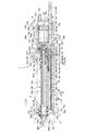
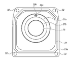
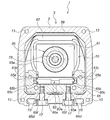
- FIG. 3 is a diagram illustrating a first embodiment of the present invention, and is a cross-sectional view taken along line III-III in FIG. It is a figure which shows the 1st Embodiment of this invention and is an enlarged view of the IV section in FIG. It is a figure which shows the 1st Embodiment of this invention and is a rear view of the front bracket used for an actuator.
- FIG. 5 is a diagram showing a first embodiment of the present invention and a cross-sectional view taken along the line VII-VII in FIG. It is a figure which shows the 2nd Embodiment of this invention, and is an expanded sectional view of the front-end
- the actuator 1 first includes a housing 3.
- the housing 3 is provided on the housing body 5, the front cover 7 provided on the front end side (left side in FIG. 3) of the housing body 5, and the rear end side (right side in FIG. 3) of the housing body 5.
- rear cover 9 An actuator body 10 is housed in the housing 3 of the actuator 1.
- the housing body 5 is a cylindrical member.
- a front opening 11a is formed at the front end (left end in FIG. 3) and the rear end ( A rear opening 11b is formed at the right end in FIG.
- female screw portions 13, 13, 13, 13 are formed on the front end surface (the lower left surface in FIG. 2) of the housing body 5, and the housing body 5 has a rear end.
- a female screw portion (not shown) similar to the female screw portions 13, 13, 13, 13 is also formed on the end surface (the upper right side surface in FIG. 2).
- a plurality of mounting bolt through holes 17 are formed in the bottom surface 15 of the housing body 5.
- mounting grooves 16, 16 are extended and formed on the bottom surface 15 of the housing body 5 in the length direction (the direction from the lower left to the upper right in FIG. 2).
- the actuator 1 is installed at an arbitrary location using the mounting grooves 16 and 16.
- a tool through hole 21 a is formed in the upper surface 19 of the housing body 5.
- the tool through hole 21a is closed by a seal cap 21b when not in use.
- the seal cap 21b is detachable from the housing body 5, and is removed when a jig (not shown) is inserted from the tool through hole 21a.
- a grease supply through hole 22 a is formed in the upper surface 19 of the housing body 5.
- the grease supply through hole 22a is closed by a seal cap 22b when not in use.
- the seal cap 22b is detachable from the housing body 5, and is removed when supplying grease as a lubricant from the grease supply through hole 22a.
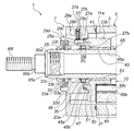
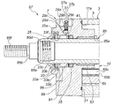
- the front cover 7 includes a front bracket 23a and a bearing bracket 23b.
- a rod through hole 25 is first formed in the front bracket 23a.
- a first seal member fitting portion 25a is formed on the front end side (left side in FIG. 4) of the rod through hole 25, and on the rear end side (right side in FIG. 4) of the rod through hole 25.
- a second seal member fitting portion 25b is formed.
- the first seal member fitting portion 25a opens forward (left side in FIG. 4) and also opens radially inward.
- the second seal member fitting portion 25b is provided as an annular groove opened inward in the radial direction.
- a grease reservoir recess 27a is formed on the surface of the front bracket 23a on the bearing bracket 23b side (right side in FIG. 4).
- the grease retaining recess 27 a is an annular groove provided on the outer peripheral side of the rod through hole 25.
- a grease reservoir convex portion 27b is formed inside the grease reservoir concave portion 27a.
- a nipple mounting recess 29a is formed on the upper surface side (upper side in FIG. 4) of the front bracket 23a, and a nipple mounting through hole 29b is formed on the bottom surface side thereof.
- the nipple mounting through hole 29b and the grease reservoir recess 27a are connected to each other by a grease supply passage 29c.
- the grease supply path 29c and the rod through hole 25 are connected to each other by a grease supply path (orifice) 29d.
- a seal member groove 31 is formed on the end surface of the front bracket 23a on the housing body 5 side. As shown in FIGS. 2 and 5, the front bracket 23 a is formed with bolt through holes 32, 32, 32, 32.
- a first rod seal member 33 is fitted to the first seal member fitting portion 25a of the front bracket 23a.
- the first rod sealing member 33 is, for example, a rubber member that has been subjected to Diamond Like Carbon coating (hereinafter abbreviated as DLC coating) as a surface hardening treatment.
- the first rod seal member 33 includes an annular portion 33a that is fitted to the first seal member fitting portion 25a, and a dust seal portion 33b that is projected and formed from the front side of the annular portion 33a. It is configured.
- the first rod seal member 33 is formed with a through hole 33c extending in the front-rear direction (left-right direction in FIG. 4).
- a soft wiper fitting portion 33d is formed on the rear end side (right side in FIG.
- the soft wiper 33e is made of felt, for example. Further, for example, a metal annular member 33f is embedded in the annular portion 33a.
- the DLC coating as a surface hardening treatment of the first rod sealing member 33 is applied to the inner surface or the whole of the first rod sealing member 33.
- the second rod seal member 35 is fitted to the second seal member fitting portion 25b of the front bracket 23a.
- the second rod sealing member 35 is a rubber member having a DLC coating applied thereto as a surface hardening treatment.
- the second rod sealing member 35 is a ring-shaped member having an X-shaped cross-sectional shape as shown in FIG.
- the DLC coating as the surface hardening treatment of the second rod seal member 35 is applied to the inner surface of the second rod seal member 35 or the entire surface.
- the width of the second seal member fitting portion 25b (the length in the left-right direction in FIG. 4, W 1 ) is set to the width of the second rod seal member 35 (the length in the left-right direction in FIG. 4, W 2 ). On the other hand, it has been given a little margin.
- a grease nipple 37 is press-fitted into the nipple mounting through hole 29b.
- a coil spring 37b and a ball 37a are housed inside the grease nipple 37.
- the ball 37a is normally urged upward in FIG. 4 by the coil spring 37b, and the grease nipple 37 is closed.
- a grease gun (not shown) is connected to the grease nipple 37 and the operation lever is operated. Then, the ball 37a is pushed down against the spring force of the coil spring 37b by the pressure of the supplied grease, and the grease is injected into the grease supply path 29c from the grease gun (not shown) through the grease nipple 37.
- the grease nipple 37, the grease supply path 29c, and the grease supply path (orifice) 29d constitute a lubricant supply section.
- the front bracket 23a allows the bolts 39, 39, 39, 39 to pass through the bolt through holes 32, 32, 32, 32, and the female thread portion on the front end surface (the lower left surface in FIG. 2) of the housing body 5.
- the housing body 5 is fixed by screwing with 13, 13, 13, and 13.
- a front cover seal member 41 is fitted in the seal member groove 31 of the front bracket 23a, and the front cover seal member 41 is interposed between the front bracket 23a and the housing body 5. It is in an inserted state.
- the front cover seal member 41 has a ring shape before being mounted, but is fitted into the seal member groove 31 to have a shape as shown in FIG.
- the bearing bracket 23b is formed with a through hole 43 extending in the front-rear direction (left-right direction in FIG. 4).
- the front end side (the left end side in FIG. 4) of the through-hole 43 has a large diameter and forms a grease retaining recess 45a, and a grease retaining projection 45b is formed on the outer peripheral side thereof.
- a stepped portion is formed on the outer peripheral surface of the grease retaining convex portion 45 b of the bearing bracket 23 b, and this stepped portion serves as an O-ring engagement portion 47.
- bolt through holes 49, 49, 49, 49 are formed in the lower part of the bearing bracket 23b on both the left and right sides.
- the front bracket 23a and the bearing bracket 23b are integrated by engaging the grease retaining recess 27a of the front bracket 23a and the grease retaining convex 45b of the bearing bracket 23b.
- a grease reservoir 50 is formed between the grease reservoir convex portion 27b and the grease reservoir concave portion 45a.
- An O-ring 51 is engaged with the O-ring engaging portion 47 of the bearing bracket 23b.
- the O-ring 51 is interposed between the inner peripheral surface of the grease retaining recess 27a of the front bracket 23a and the outer peripheral surface of the grease retaining convex portion 45b of the bearing bracket 23b.
- a cylindrical bearing 53 is housed on the rear end side (right side in FIG. 4) of the through hole 43 of the bearing bracket 23b.
- the rear cover 9 As shown in FIGS. 2 and 3, the rear cover 9 is formed with a hollow portion 55 opened to the housing body 5 side (left side in FIG. 3). An intake / exhaust port through hole 57a and a cable through hole 57b are formed on the rear end side (right side in FIG. 3) of the rear cover 9. A seal member groove 59 is formed on the end surface of the rear cover 9 on the housing body 5 side (left side in FIG. 3). As shown in FIG. 2, the rear cover 9 is formed with bolt through holes 61, 61, 61, 61.
- the rear cover 9 has bolts 39, 39, 39, 39 inserted through the bolt through holes 61, 61, 61, 61, and the rear end surface (upper right surface in FIG. 2) of the housing body 5 is not shown.
- the housing body 5 is fixed by being screwed into the female screw portion.
- a rear cover seal member 62 is fitted in the seal member groove 59 of the rear cover 9, and the rear cover seal member 62 is inserted between the rear cover 9 and the housing body 5. It has become.
- the rear cover seal member 62 has a ring shape before being mounted, but is fitted into the seal member groove 59 to have a shape as shown in FIG.
- an intake / exhaust port 63 is provided through the intake / exhaust port through hole 57a.
- a cable 64 is installed through the cable through hole 57b.
- the cable 64 is a bundle of power lines, signal lines, and the like.
- the actuator body 10 has a base 65, and the base 65 has a U-shaped cross section as shown in FIG. Further, as shown in FIG. 7, guide rail grooves 65a extended in the length direction (perpendicular to the plane of the paper in FIG. 7) are formed on the inner side surfaces of both ends of the base 65 in the width direction (left and right direction in FIG. 7). , 65a are formed. Guide rails 65b and 65b are press-fitted into the guide rail grooves 65a and 65a, respectively. The guide rails 65b and 65b are respectively provided with guide recesses 65c and 65c extending in the length direction (perpendicular to the paper surface in FIG. 7).
- a plurality of female screw portions 65d are formed on the bottom surface side (lower side in FIG. 7) of the base 65. In FIG. 7, two of the plurality of female screw portions 65d are shown.
- the base 65 and the housing main body 5 are fixed by screwing bolts 65 e through the mounting bolt through holes 17 of the housing main body 5 and screwing into the female screw portions 65 d of the base 65.
- a washer-like housing seal member 65f is interposed between the head of the bolt 65e and the housing body 5.
- the positioning of the base 65 and the housing body 5 is performed by inserting positioning pins 68 into the positioning holes 66 drilled on the base 65 side and the positioning holes 5a drilled on the housing body 5 side. Done.
- the lid 70 is attached from the top where the positioning pin 68 is inserted.
- the bearing bracket 23b already described is fixed to the front end surface of the base 65 (the lower left surface in FIG. 6).
- the base 65 and the bearing bracket 23b are formed by passing four bolts 65g through the bolt through-holes 49, 49, 49, 49 of the bearing bracket 23b to form four female screw portions (not shown) of the base 65. It is fixed by screwing to each.
- the diameter of the bolt through hole 49 of the bearing bracket 23b is such that play is provided with respect to the diameter of the bolt 65g. Therefore, the mounting position of the bearing bracket 23b with respect to the base 65 can be adjusted within the range of play. Further, by adjusting the mounting position of the bearing bracket 23b with respect to the base 65, the axial center of the rod 85 described later can be adjusted.
- a bearing housing 67 is installed at the rear end portion (right end in FIG. 3) of the base 65.
- the bearing housing 67 is a hollow member opened on the front end side (left side in FIG. 3) and the rear end side (right side in FIG. 3).
- the bearing housing 67 includes ball bearings 67a and 67a.
- the ball bearing 67a includes an outer ring 67b and an inner ring 67c installed inside the outer ring 67b.
- a retainer 67d having a plurality of through holes is provided between the outer ring 67b and the inner ring 67c, and balls 67e are held in the plurality of through holes of the retainer 67d. As the plurality of balls 67e roll, the inner ring 67c rotates with respect to the outer ring 67b.
- the outer ring 67b of the ball bearing 67a on the front end side is in contact with the front end side (left side in FIG. 3) of the inner surface of the bearing housing 67.
- a ball bearing fixing member 67f is installed on the rear end side (right side in FIG. 3) of the ball bearing 67a on the rear end side (right side in FIG. 3).
- the ball bearing fixing member 67f is in contact with the outer ring 67b of the ball bearing 67a on the rear end side (right side in FIG. 3).
- the base 65 and the bearing housing 67 are fixed by screwing bolts (not shown) through the bearing housing 67 and screwing the bolts to a plurality of female screw portions (not shown) of the base 65. .
- the through hole of the bearing housing 67 has a size with play with respect to the bolt, and the position of the bearing housing 67 with respect to the base 65 can be adjusted within the range of the play. Has been.
- a motor bracket 69 is installed behind the bearing housing 67 (on the right side in FIG. 3).
- a through hole 69 a is formed in the motor bracket 69.
- the front end side (the left side in FIG. 3) of the through hole 69a has a large diameter, and serves as a bearing housing engaging portion 69b.
- the bearing housing 67 and the motor bracket 69 are integrated by engaging the rear end side (the right side in FIG. 3) of the bearing housing 67 with the bearing housing engaging portion 69b.
- a set screw female thread 69c is formed on the front end side (left side in FIG. 3) of the upper part (upper part in FIG. 3) of the motor bracket 69.
- the motor bracket 69 and the bearing housing 67 are configured such that the set screw 71 is screwed into the female screw portion 69c for the set screw of the motor bracket 69, and the upper surface on the rear end side (right side in FIG. 3) of the bearing housing 67. It is fixed by pressing (upper surface in FIG. 3). Therefore, the motor bracket 69 is separated from the bearing housing 67 only by removing the set screw 71.
- the set screw 71 is screwed into and removed from the set screw female thread 69c by a jig (not shown) inserted from the tool through hole 21a of the housing body 5.
- the actuator body 10 has a motor 73.
- the motor 73 has a motor case 73a, and a stator 73b is fixed to the inner peripheral side of the motor case 73a.
- a rotor 73c made of a permanent magnet is rotatably mounted on the inner peripheral side of the stator 73b.
- An output shaft 73d is fixed to the center position of the rotor 73c.
- the motor 73 is driven by electric power supplied via the cable 64. When electric power is supplied via the cable 64, the rotor 73c and the output shaft 73d are integrally rotated forward and reverse.
- the front end side (left end side in FIG.
- an encoder 75 is installed on the rear end side (right side in FIG. 3) of the motor 73.
- the encoder 75 has an encoder cover 75a installed on the rear end side (right side in FIG. 3) of the motor case 73a.
- a substrate 75c is installed on the rear end surface (the right side surface in FIG. 3) of the motor case 73a via three bar-shaped spacers 75b.
- Electronic components 75d and 75e are mounted on the substrate 75c.
- a code wheel 75f is fixed to a portion of the output shaft 73d of the motor 73 that protrudes into the encoder cover 75a.
- An encoder scale (not shown) is displayed on the rear end surface (the right side surface in FIG. 3) of the code wheel 75f.
- the encoder scale (not shown) provides a portion where the intensity of reflected light reflected is high and a portion where the reflected light is strong on the rear end surface (the right side surface in FIG. 3) of the code wheel 75f.
- a light source and a sensor are mounted on the back surface (the left surface in FIG. 3) of the substrate 75c on which the electronic components 75d and 75e are provided.
- the encoder scale (not shown) is irradiated with light from the light source, and the reflected light is detected by the sensor. Thus, the direction and position of rotation of the output shaft 73d of the motor 73 are detected.
- the motor bracket 69 is separated from the bearing housing 67 simply by removing the set screw 71.
- the motor 73 and the encoder 75 are integrated with the motor bracket 69. Therefore, the portion where the motor bracket 69, the motor 73, and the encoder 75 are integrated can be separated from the actuator body 10 simply by removing the set screw 71.
- a coupling member 76a which is a part of an Oldham coupling
- a coupling member 76c which is another part of the Oldham coupling
- a coupling member 76d which is still another part of the Oldham coupling, is inserted and engaged between the coupling member 76a and the coupling member 76c.
- the output shaft 73d of 73 and the ball screw connecting member 77 are connected.
- the coupling members 76a, 76c and 76d are installed in the through hole 69a of the motor bracket 69.
- the ball screw connecting member 77 is press-fitted into the inner rings 67 c and 67 c of the ball bearings 67 a and 67 a housed in the bearing housing 67.
- a connection hole 77a is formed in the ball screw coupling member 77, and a ball screw 78 is press-fitted and fixed in the connection hole 77a. That is, the ball screw 78 includes a screw portion 78 a and a rear end side (right side in FIG. 3) connection portion 78 b, and the connection portion 78 b is press-fitted into the connection hole 77 a of the ball screw coupling member 77. .
- a male screw portion 78 c is formed on the outer peripheral surface of the screw portion 78 a of the ball screw 78.
- a ball nut 79 having a female screw portion (not shown) is screwed and arranged on the ball screw 78.
- the ball nut 79 has a ball nut main body 79a.
- End caps 79c and 79c are installed at front and rear ends of the ball nut main body 79a (right and left ends in FIG. 3).
- the ball nut body 79a is formed with a non-load circulation path (not shown), and the end caps 79c and 79c are respectively formed with return paths (not shown). Then, by rotating the ball screw 78, the ball nut 79 reciprocates.
- the one end cap 79c is interposed between a male screw portion 78c of the ball screw 78 and a female screw portion (not shown) of the ball nut 79.
- a plurality of balls (not shown) circulate through the return path, the no-load circulation path, and the return path of the other end cap 79c, thereby realizing a smooth reciprocation of the ball nut 79.
- a rod connecting member 81 is fixed to the ball nut 79.
- the ball screw 78 is coaxially housed inside the rod connecting member 81.
- a female threaded portion 81a is formed on the front end side (left side in FIG. 3) of the rod connecting member 81.
- a grease nipple 81b is installed in the upper portion (upper portion in FIG. 3) of the rod connecting member 81 so as to penetrate the rod connecting member 81.
- the grease nipple 81b communicates with a no-load circulation path (not shown) of the ball nut 79.
- a coil spring (not shown) and a ball 81b ' are housed inside the grease nipple 81b.
- the ball 81b' is normally urged upward in FIG.
- a guided portion 83 is fixed to the rod connecting member 81.
- the guided portion 83 has a guided portion main body 83a.
- a recess extends and is formed in the front-rear direction (the direction perpendicular to the paper surface in FIG. 7).
- unloaded circulation paths are formed on both sides in the width direction (both sides in the left-right direction in FIG. 7) of the guided portion main body 83a and inside the recesses (not shown).
- end caps 83b and 83b are installed on both ends of the guided portion main body 83a in the width direction (left side in FIG. 7) and in the front-rear direction (perpendicular direction in FIG. 7).
- End caps 83c and 83c are provided at both ends of the guide portion main body 83a in the width direction on the other end side (right side in FIG. 7) and in the front-rear direction (vertical direction in FIG. 7).
- a return path (not shown) is formed in these end caps 83b, 83b, 83c, 83c.
- a plurality of balls (not shown) circulate in the space between the recess not to be formed and the guide recess 65c of the guide rail 65b on one end side in the width direction (left side in FIG. 7). Further, the above-described unloaded circulation path (not shown) on the other end side in the width direction (right side in FIG. 7), the return path (not shown) in the end caps 83c and 83c, and the other end side in the width direction (right side in FIG. 7). A plurality of balls (not shown) circulate also in the space between the recess (not shown) and the guide recess 65c of the guide rail 65b on the other end side in the width direction (right side in FIG. 7).
- the ball nut 79 is smoothly guided in the front-rear direction (the direction perpendicular to the paper surface in FIG. 7).
- the rotation of the ball nut 79 is restricted by the base 65 through the guided portion 83, and the ball nut 79 is moved in the length direction of the ball screw 78 (left and right in FIG. 3). Direction) will move to both sides.
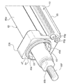
- a rod 85 is connected to the rod connecting member 81.
- the rod 85 includes a hollow cylindrical rod body 85a and an object mounting member 85b installed on the distal end side of the rod body 85a.
- a male screw portion 85c is formed on the outer peripheral surface of the rear end side (right end side in FIG. 3) of the rod body 85a.
- the rod 85 is coupled to the rod coupling member 81 by screwing the male thread 85 c into the female thread 81 a of the rod coupling member 81.
- An internal thread portion 85d is formed on the inner peripheral surface of the front end side (left end side in FIG. 3) of the rod body 85a.
- a male screw portion 85e is formed on the rear end side (right end side in FIG. 3) of the object mounting member 85b.
- the said object attachment member 85b is attached to the said rod main body 85a because the external thread part 85e of the said object attachment member 85b is screwed by the internal thread part 85d of the said rod main body 85a. Further, the outer peripheral surface of the rod body 85a is subjected to hard chrome plating as a surface hardening treatment.
- the ball screw 78 is accommodated coaxially in the rod 85.
- a male screw portion 85f is formed on the distal end side of the object mounting member 85b.
- the object (not shown) is attached to the rod 85 by screwing the female screw part (not shown) into the male screw part 85f.
- the rod 85 passes through the bearing 53 housed in the bearing bracket 23a, the rod through-hole 25 for the front bracket, the second rod seal member 35, the soft wiper 33e, and the first rod seal member 33. Projecting out of the housing 3.
- the rod 85 is slidably in contact with the first rod seal member 33, the second rod seal member 35, the soft wiper 33 e, and the inner peripheral surface of the bearing 53.
- a pressure change absorbing groove 86 is formed on the inner peripheral surface of the rod through hole 25.
- the pressure change absorbing groove 86 is annularly formed between the first rod seal member 33 and the second rod seal member 35.
- the pressure change absorbing groove 86 is provided in communication with the already-described grease supply path (orifice) 29d.
- the pressure change absorbing groove 86 is for absorbing the pressure change of the grease generated when the rod 85 advances and retreats by accommodating the grease therein, and thereby the first rod sealing member.
- the grease is prevented from flowing out of the housing 3 through the gap between the rod 33 and the rod 85, and an appropriate amount of grease is supplied to the outer peripheral surface of the rod 85 from the lubricant supply section. Further, not all of the pressure change absorbing groove 86 is filled with the grease, and a part of the air layer is formed.
- the operation of the actuator 1 will be described.
- the motor 73 is driven by an operation instruction transmitted through a signal line (not shown) of the cable 64
- the output shaft 73d is rotated at a direction and speed according to the operation instruction.
- the rotation of the output shaft 73d is transmitted to the ball screw 78 via the Oldham coupling including the coupling members 76a, 76c and 76d and the ball screw connecting member 77, and the ball screw 78 also has the same direction as the output shaft 73d. Rotated at speed.
- the ball nut 79 screwed to the ball screw 78 moves in any direction of the length direction of the ball screw 78 (left and right direction in FIG. 3). This is because the ball nut 79 tries to rotate in the same direction as the rotation direction of the ball screw 78 by the rotational force of the ball screw 78, but the guided portion 83 connected to the ball nut 79 is a guide rail of the base 65. This is because the rotation of the ball nut 79 due to the rotation of the ball screw 78 is restricted because it is guided in the length direction (left and right direction in FIG. 3) by 65b and 65b. As the ball nut 79 moves, the rod 85 and the object (not shown) attached to the rod 85 are also moved in the length direction of the ball screw 78 (left and right in FIG. 3).
- a grease reservoir 50 is formed between the front bracket 23a and the bearing bracket 23b.
- grease (not shown) is held.
- the grease passes through the grease supply passages 29c and 29d and enters the pressure change absorption groove 86, and from there, the rod 85 moves to the front side of the second rod seal member 35 (left side in FIG. 4).
- the rod 85 moves to the rear side (right side in FIG. 4) of the second rod seal member 35.
- grease is filled in the unloaded circulation path (not shown) of the ball nut 79.
- the grease makes smooth rolling of a plurality of balls (not shown) in a space between the spiral male screw portion 78c of the ball screw 78 and a female screw portion (not shown) of the ball nut 79.
- the replenishment of grease into the unloaded circulation path (not shown) of the ball nut 79 is performed through the grease replenishing through hole 22a of the housing body 5 and the grease nipple 81b of the rod connecting member 81.
- the axis of the rod 85 is adjusted at the time of assembly in order to make the movement of the rod 85 smooth. That is, as shown in FIG. 6, before the front bracket 23a, the first rod seal member 33, the soft wiper 33e, and the second rod seal member 35 are attached, the four bolts 65g are tightened.
- the bearing bracket 23 b can be freely moved within the play range of the bolt through hole 49.
- the bearing housing 67 can be freely moved within the range of play with respect to the base 65 before the bolt (not shown) is tightened. In this state, first, the rod 85 is pushed to the right side in FIG.
- a front cover seal member 41 is interposed between the housing body 5 and the front bracket 23a, and a rear cover seal is interposed between the housing body 5 and the rear cover 9.
- a member 62 is inserted.
- the front cover sealing member 41 and the rear cover sealing member 62 prevent foreign matter and water droplets from entering the housing 3 at both end surfaces of the housing body 5.
- a washer-like housing seal member 65 f is interposed between the head of the bolt 65 e and the housing body 5.
- the housing seal member 65f prevents foreign matter, water droplets, and the like from entering the housing 3 through the through hole 17 of the housing body 5.
- a first rod sealing member 33 and a second rod sealing member 35 are installed on the front bracket 23a.
- the first rod sealing member 33 and the second rod sealing member 35 prevent foreign matter, water droplets, and the like from entering the inside of the housing 3 in the portion of the housing 3 through which the rod 85 passes. This point will be described in more detail.
- the first rod seal member 33 is installed on the outer side (left side in FIG. 3) of the rod through-hole 25, and the second rod seal member 35 is installed on the inner side of the rod through-hole 25 (see FIG. (Right side of 3).
- the second rod seal member 35 causes the foreign matter, water droplets, or the like to be inside the housing 3. Further intrusion into is prevented. That is, entry of foreign matter or water droplets into the housing 3 is prevented in two stages.
- a soft wiper 33e is installed on the rear end side (right side in FIG. 3) of the inner peripheral surface of the first rod sealing member 33.
- the soft wiper 33e also exhibits a desired sealing function between the first rod sealing member 33 and the second rod sealing member 35, and captures the foreign matter, water droplets, and the like. Yes.
- the first rod sealing member 33 and the second rod sealing member 35 are made of grease (not shown) or wear powder generated inside the housing 3 from the inside of the housing 3 to the outside. It also prevents the outflow of foreign matter.
- the soft wiper 33e also prevents foreign matter such as grease and wear powder from flowing out of the housing 3.
- An O-ring 51 is inserted between the inner peripheral surface of the grease retaining recess 27a of the front bracket 23a and the outer peripheral surface of the grease retaining convex portion 45b of the bearing bracket 23b. The O-ring 51 prevents grease (not shown) from flowing out in the grease reservoir 50.
- the second rod sealing member 35 is also moved rearward (right side in FIG. 4) and its width (length in the left-right direction in FIG. 4) is reduced. Deformed. Therefore, a gap is generated between the second rod seal member 35 and the front surface (the left surface in FIG. 4) of the second seal member fitting portion 25b. And grease enters this gap. Due to the movement of the grease, the air pressure in the air layer of the pressure change absorbing groove 86 is reduced, and as a result, the grease is supplied from the grease supply path 29c and the grease reservoir 50 through the grease supply path (orifice) 29d. It will be. Since this grease is accommodated in the pressure change absorbing groove 86, excessive grease is not supplied to the outer peripheral surface of the rod 85. Further, the amount of grease that cannot be held by the soft wiper 33e is not supplied.
- a pressure change absorbing groove 86 is formed on the inner peripheral surface of the rod through hole 25 between the first rod seal member 33 and the second rod seal member 35.
- the grease is moved forward by the movement of the rod 85 and the movement of the rod 85 to the front side (left side in FIG. 4) of the second rod sealing member 35.
- the left side of FIG. 4 is energized, and the grease pressure changes.
- a part of the grease moved to the front side enters the pressure change absorption groove 86, and the pressure change of the grease is absorbed.
- the air layer in the pressure change absorbing groove 86 is compressed.
- the second rod sealing member 35 When the rod 85 is retracted, the second rod sealing member 35 is also moved rearward (right side in FIG. 4) and its width (length in the left-right direction in FIG. 4, W 2 ) is small. It is transformed to become. Therefore, a gap is generated between the second rod seal member 35 and the front surface (the left surface in FIG. 4) of the second seal member fitting portion 25b. And grease enters this gap. Due to the movement of the grease, the air pressure in the air layer of the pressure change absorbing groove 86 is reduced, and as a result, the grease is supplied from the grease supply path 29c and the grease reservoir 50 through the grease supply path (orifice) 29d.
- front cover 7 and the rear cover 9 are not attached to each other on both end surfaces of the housing body 5 but have a detachable mounting structure via bolts 39, so that the housing 3 can be easily disassembled and assembled. It has become a thing.
- a front cover seal member 41 is interposed between the housing body 5 and the front bracket 23a, and a rear cover seal member 62 is interposed between the housing body 5 and the rear cover 9. Therefore, it is possible to reliably prevent foreign matter, water droplets, and the like from entering the inside of the housing 3 at both end faces of the housing body 5 and to improve the dustproof / waterproof performance of the actuator 1.
- first rod seal member 33 and the second rod seal member 35 are installed in the front bracket 23a, the first rod seal member 33 and the second rod seal member 35 are used to form the housing. Intrusion of foreign matter, water droplets or the like into the inside of the housing 3 at a portion through which the three rods 85 penetrate can be prevented.
- the first rod seal member 33 is installed on the outer side (left side in FIG. 3) of the rod through-hole 25, and the second rod seal member 35 is installed on the inner side of the rod through-hole 25 ( It is also installed on the right side in FIG. Therefore, even if foreign matter or water droplets or the like enter from the gap between the first rod seal member 33 and the rod 85, the second rod seal member 35 causes the foreign matter or water droplets or the like to enter the housing 3. Further intrusion into can be prevented. That is, it is possible to prevent further intrusion of the foreign matter and water droplets into the housing 3 in two stages.
- a soft wiper 33e is installed on the rear end side (right side in FIG. 3) of the inner peripheral surface of the first rod seal member 33, the soft wiper 33e and the first rod seal member 33 A sealing function can be exhibited between the second rod sealing member 35 and the foreign matter, water droplets, and the like can be captured.
- first rod sealing member 33 and the second rod sealing member 35 prevent outflow of foreign matters such as grease (not shown) and abrasion powder generated inside the housing 3 from the inside of the housing 3 to the outside. You can also. Further, as in the case of entry of foreign matter or water droplets from the outside of the housing 3 described above, a two-stage rod seal member, the first rod seal member 33 and the second rod seal member 35, is installed. Therefore, it is possible to more reliably prevent foreign matters such as the grease and wear powder generated inside the housing 3 from flowing out. Further, the soft wiper 33e can also prevent foreign matters such as the grease to the outside of the housing 3 and the wear powder generated inside the housing 3 from flowing out.
- the first rod sealing member 33, the second rod sealing member 35, and the soft wiper 33e can enhance the dustproof and waterproof performance of the actuator 1. Further, since the soft wiper 33e holds the grease, the grease can be supplied to the outer peripheral surface of the rod 85 by the soft wiper 33e.
- the second rod sealing member 35 is a ring-shaped member having an X-shaped cross-sectional shape, and rods are provided at two positions on the front end side (left side in FIG. 4) and the rear end side (right side in FIG. 4). Since it is in contact with 85, dustproof and waterproof performance can be enhanced. Further, since the second rod sealing member 35 has a small contact area with the rod 85, the sliding resistance can be reduced. In addition, since a housing seal member 65f is interposed between the head of the bolt 65e and the housing body 5, it is possible to ensure that foreign matter, water droplets, etc. enter the through hole 17 into the housing 3. And the dustproof / waterproof performance of the actuator 1 can be improved.
- the front cover 7 is composed of a front bracket 23a and a bearing bracket 23b, and a grease reservoir 50 is formed between the front bracket 23a and the bearing bracket 23b. Therefore, the grease reservoir 50 can be easily formed. Moreover, the movement of the rod 85 can be facilitated by the grease retained in the grease reservoir 50. Further, since the grease is held also on the first rod seal member 33 side by the soft wiper 33e, the rod 85 can be moved more smoothly. Since both the first rod sealing member 33 and the second rod sealing member 35 are installed on the front bracket 23a side, the first rod can be easily removed by removing only the front bracket 23a. The seal member 33 and the second rod seal member 35 can be exchanged.
- the rod 85 is moved in the axial direction. Even when they are used, there is no influence of frictional resistance, and the axial center adjustment of the rod 85 can be easily performed.
- the first rod seal member 33 and the second rod seal member 35 are DLC coated as a surface hardening treatment, and the outer surface of the rod 85 is hard chrome plated as a surface hardening treatment. Has been. Therefore, the friction coefficient between the first rod seal member 33 and the second rod seal member 35 and the rod 85 can be reduced to realize a smooth operation of the actuator 1 and the first rod seal. The wear resistance of the seal member 33, the second rod seal member 35, and the rod 85 can be improved.
- the actuator body 10 is configured by integrating the bearing housing 67, the motor bracket 69, the motor 73, the ball screw 78, the ball nut 79, the rod 85, and the like with the base 65, the actuator into the housing 3 is formed.
- the actuator can be easily assembled and disassembled by removing the actuator body 10 from the interior of the body 10 and the housing 3.
- the motor bracket 69 and the bearing housing 67 are fixed by a set screw 71. Therefore, the part where the motor bracket 69, the motor 73, and the encoder 75 are integrated can be easily separated from the actuator body 10 simply by removing the set screw 71. Further, if the rear cover 9 of the housing 3 is removed, a portion in which the motor bracket 69, the motor 73 and the encoder 75 are integrated can be easily taken out of the housing 3, and the motor 73 and the encoder can be removed. Repair and replacement of 75 etc. can be made easy.
- the actuator 87 according to the second embodiment has substantially the same configuration as the actuator 1 according to the first embodiment described above, but the front cover 89 is the front cover 7 according to the first embodiment described above. Thus, it is not composed of two members, the front bracket 23a and the bearing bracket 23b, but is composed of one member. Therefore, the grease reservoir 50 present in the front cover 7 in the first embodiment described above is not formed. Further, since it is composed of one member, the front cover 89 is also provided with an O-ring 51 provided between the front bracket 23a and the bearing bracket 23b in the first embodiment described above. It has not been.
- the rod through hole 25 is a through hole penetrating the entire front cover 89, and a bearing 53 is installed on the rear end side (right end side in FIG. 8). It becomes the composition.
- the actuator 87 according to the second embodiment also has substantially the same operation as the actuator 1 according to the first embodiment described above.
- the actuator 87 since there is no grease accumulation in the front cover 89, the grease is not held in the grease accumulation or supplied from the grease accumulation. It is possible to provide a grease reservoir by drilling or the like.
- the actuator 87 according to the second embodiment can achieve substantially the same effect as the actuator 1 according to the first embodiment described above.
- the front cover 89 is composed of a single member, the number of parts is reduced, parts management is facilitated, and the manufacturing cost can be reduced. Also, the configuration is simplified.
- the present invention is not limited to the first and second embodiments described above.
- two rod sealing members, the first rod sealing member 33 and the second rod sealing member 35 are provided as rod sealing members. It is also conceivable to provide three or more rod sealing members.
- the guided portion 83 has been described as an example of a configuration in which the guided portion 83 is slidably guided by rolling with respect to the guide rails 65b and 65b. It may be a linear guide.
- the pressure change absorbing groove 86 is an annular groove, but may be provided intermittently in the circumferential direction. However, at least one of the plurality of intermittently provided grooves needs to communicate with the grease supply path (orifice) 29d. It is also conceivable to provide a plurality of pressure change absorbing grooves 86 in the axial direction. Further, the shape and size of the pressure change absorbing groove 86 are not particularly limited. Various types of surface hardening treatments can be considered for the surface of the rod body 85a, the first rod seal member 33, and the second rod seal member 35.
- both the first rod sealing member 33 and the second rod sealing member 35 are subjected to DLC coating as a surface hardening treatment. It is also conceivable that only one of the first rod sealing member 33 and the second rod sealing member 35 is subjected to DLC coating as a surface hardening treatment. It is also conceivable that the surface hardening treatment is performed only on the rod body 85a side, or the surface hardening treatment is performed only on the first rod sealing member 33 or the second rod sealing member 35 side. In addition, the present invention is not limited to the illustrated configuration, and various modifications can be considered.
- the present invention relates to an actuator used in, for example, an industrial robot, and in particular, by providing a pressure change absorbing groove that absorbs a pressure change accompanying the advance and retreat of the rod, the rod is moved to the outside of the housing when the rod is advanced / retracted.
- an actuator used in a food manufacturing robot which is devised so as to prevent the lubricant from flowing out.
Landscapes
- Engineering & Computer Science (AREA)
- General Engineering & Computer Science (AREA)
- Mechanical Engineering (AREA)
- Physics & Mathematics (AREA)
- Fluid Mechanics (AREA)
- Power Engineering (AREA)
- Transmission Devices (AREA)
- Connection Of Motors, Electrical Generators, Mechanical Devices, And The Like (AREA)
Abstract
Description
よって、上記モータが回転することにより上記中空状回転軸が回転され、この中空状回転軸の回転によってナットも一体的に回転される。このナットの回転によって上記出力用ネジがその長さ方向両側に直線運動することになる。
また、上記ケースの両端の開口部はエンドプレートによってそれぞれ固着・閉塞されている。
まず、前述したリニアアクチュエータにおいては、エンドプレートがケースの両端に対して固着されている。固着の方法としては、例えば、接着剤の使用が考えられるが、仮に、接着剤による固着の場合には、リニアアクチュエータの組立・分解が困難になってしまうという問題があった。
また、接着剤による固着の場合には、別途シール部材を介在させることはなく、専ら、接着剤のみによってシール性能を得ることになる。しかしながら、接着剤のみで所望のシール性能を得ることは困難であった。
すなわち、特願2012-193195に係るアクチュエータにおいては、ロッドが移動する際にハウジング内の潤滑剤としてのグリスに急激な圧力変化が生じてしまう。そして、この急激な圧力変化により、上記ロッドが前進する際には、ソフトワイパによって保持できないほど多くのグリスが前方に移動されて、上記ロッドの外周面と上記ハウジングの前端側に設置されたロッド用シール部材との間から上記ハウジング外部へ流出してしまうという問題があった。
また、上記ロッドが後退する際には、潤滑剤供給部としてのグリスニップル及びグリス供給路から上記ロッドの外周面へとグリスが過剰に供給され、このグリスの一部が上記ソフトワイパによって保持しきれず上記ロッドの外周面と上記ロッド用シール部材との間から上記ハウジング外部へ流出してしまうという問題があった。
また、請求項2に記載されたアクチュエータは、請求項1記載のアクチュエータにおいて、上記潤滑剤供給部はオリフィスを備えていて、上記圧力変化吸収用溝は上記オリフィスに連通した状態で設けられていることを特徴とするものである。
また、請求項3に記載されたアクチュエータは、請求項2記載のアクチュエータにおいて、上記圧力変化吸収用溝は環状に設けられていることを特徴とするものである。
また、請求項4に記載されたアクチュエータは、請求項1~請求項3の何れかに記載のアクチュエータにおいて、上記圧力変化吸収用溝よりハウジング外部側には上記ロッドを貫通し上記潤滑剤を保持するソフトワイパが設置されていることを特徴とするものである。
また、請求項5に記載されたアクチュエータは、請求項1~請求項4の何れかに記載のアクチュエータにおいて、上記ハウジングは両端にフロント開口部とリア開口部を備えたハウジング本体と、上記フロント開口部を閉塞するフロントカバと、上記リア開口部を閉塞するリアカバとから構成されており、上記フロントカバと上記ハウジング本体との間にはフロントカバ用シール部材が介挿されており、上記リアカバと上記ハウジング本体との間にはリアカバ用シール部材が介挿されていることを特徴とするものである。
また、請求項6に記載されたアクチュエータは、請求項5記載のアクチュエータにおいて、上記ハウジング本体内にはアクチュエータ本体が内装されていて、このアクチュエータ本体は、モータと、該モータにより回転されるネジと該ネジに螺合されるナットと、該ナットに固着される上記ロッドと、から構成されていることを特徴とするものである。
また、請求項7に記載されたアクチュエータは、請求項5又は請求項6記載のアクチュエータにおいて、上記フロントカバは、フロントブラケットと、該フロントブラケットの軸方向内側に配置された軸受ブラケットと、から構成されており、上記フロントブラケットと軸受ブラケットとの間にはグリス溜りが設けられていることを特徴とするものである。
また、請求項8に記載されたアクチュエータは、請求項7記載のアクチュエータにおいて、上記第1ロッド用シール部材及び第2ロッド用シール部材は上記フロントブラケット側に設けられていることを特徴とするものである。
また、請求項9に記載されたアクチュエータは、請求項1~請求項8の何れかに記載のアクチュエータにおいて、上記ロッドの外表面には表面硬化処理が施されていることを特徴とするものである。
また、請求項10に記載されたアクチュエータは、請求項9記載のアクチュエータにおいて、上記ロッドに施された表面硬化処理は硬質クロムメッキであることを特徴とするものである。
また、請求項11に記載されたアクチュエータは、請求項1~請求項8の何れかに記載のアクチュエータにおいて、上記第1ロッド用シール部材及び第2ロッド用シール部材の少なくとも内表面には表面硬化処理が施されていることを特徴とするものである。
また、請求項12に記載されたアクチュエータは、請求項11記載のアクチュエータにおいて、上記第1ロッド用シール部材及び第2ロッド用シール部材に施された表面硬化処理はDLC(Diamond Like Carbon)コーティングであることを特徴とするものである。
また、請求項13に記載されたアクチュエータは、請求項6~請求項12の何れかに記載のアクチュエータにおいて、上記アクチュエータ本体はハウジングの外側からねじ部材を螺合することによりハウジングに固定されていて、上記ネジ部材の上記ハウジングの貫通部にはハウジング用シール部材が設置されていることを特徴とするものである。
また、請求項2記載のアクチュエータによると、請求項1記載のアクチュエータにおいて、上記潤滑剤供給部はオリフィスを備えていて、上記圧力変化吸収用溝は上記オリフィスに連通した状態で設けられているため、上記圧力変化を効果的に吸収することができるとともに、上記オリフィスを介して上記潤滑剤供給部から適切な量の潤滑剤を供給することができる。
また、請求項3記載のアクチュエータによると、請求項2記載のアクチュエータにおいて、上記圧力変化吸収用溝は環状に設けられているため、上記圧力変化をより効果的に吸収することができる。
また、請求項4に記載されたアクチュエータは、請求項1~請求項3の何れかに記載のアクチュエータにおいて、上記圧力変化吸収用溝よりハウジング外部側には上記ロッドを貫通し上記潤滑剤を保持するソフトワイパが設置されているため、上記ソフトワイパによって上記潤滑剤を保持させることで上記潤滑剤の外部への流出を防止できるとともに、上記ソフトワイパによっても上記ロッド外周面に上記潤滑剤を供給することができる。
また、請求項5に記載されたアクチュエータは、請求項1~請求項4の何れかに記載のアクチュエータにおいて、上記ハウジングは両端にフロント開口部とリア開口部を備えたハウジング本体と、上記フロント開口部を閉塞するフロントカバと、上記リア開口部を閉塞するリアカバとから構成されており、上記フロントカバと上記ハウジング本体との間にはフロントカバ用シール部材が介挿されており、上記リアカバと上記ハウジング本体との間にはリアカバ用シール部材が介挿されているため、容易に上記アクチュエータの組立・分解を行うことができるとともに防塵・防水性を高めることができる。
また、請求項6に記載されたアクチュエータは、請求項5記載のアクチュエータにおいて、上記ハウジング本体内にはアクチュエータ本体が内装されていて、このアクチュエータ本体は、モータと、該モータにより回転されるネジと該ネジに螺合されるナットと、該ナットに固着される上記ロッドと、から構成されているため、より容易に上記アクチュエータの組立・分解を行うことができる。
また、請求項7に記載されたアクチュエータは、請求項5又は請求項6記載のアクチュエータにおいて、上記フロントカバは、フロントブラケットと、該フロントブラケットの軸方向内側に配置された軸受ブラケットと、から構成されており、上記フロントブラケットと軸受ブラケットとの間にはグリス溜りが設けられているため、例えば、上記フロントブラケットや上記軸受ブラケットの互いに向かい合う側に溝を形成することによって、複雑な加工を要することなく、容易に上記グリス溜りを形成することができる。
また、請求項8に記載されたアクチュエータは、請求項7記載のアクチュエータにおいて、上記第1ロッド用シール部材及び第2ロッド用シール部材は上記フロントブラケット側に設けられているため、上記フロントブラケットを取り外すだけで、容易に上記ロッド用シール部材の交換を行うことができる。また、上記フロントブラケットを取り外すだけで上記ロッド用シール部材が除去された状態となるため、上記ロッド用シール部材による摺動抵抗が生じない状態において上記ロッドの軸心調整を容易に行うことができる。
また、請求項9に記載されたアクチュエータは、請求項1~請求項8の何れかに記載のアクチュエータにおいて、上記ロッドの外表面には表面硬化処理が施されているため、上記ロッドとロッド用シール部材間の摩擦係数を減少させて滑らかな動作を行うことができるとともに、耐摩耗性を高めることができる。
また、請求項10に記載されたアクチュエータは、請求項9記載のアクチュエータにおいて、上記ロッドに施された表面硬化処理は硬質クロムメッキであるため、より耐摩耗性を高めることができる。
また、請求項11に記載されたアクチュエータは、請求項1~請求項8の何れかに記載のアクチュエータにおいて、上記第1ロッド用シール部材及び第2ロッド用シール部材の少なくとも内表面には表面硬化処理が施されているため、上記ロッドと上記ロッド用シール部材間の摩擦係数を減少させて滑らかな動作を行うことができるとともに、耐摩耗性を高めることができる。
また、請求項12に記載されたアクチュエータは、請求項11記載のアクチュエータにおいて、上記第1ロッド用シール部材及び第2ロッド用シール部材に施された表面硬化処理はDLC(Diamond Like Carbon)コーティングであるため、より耐摩耗性を高めることができる。
また、請求項13に記載されたアクチュエータは、請求項6~請求項12の何れかに記載のアクチュエータにおいて、上記アクチュエータ本体はハウジングの外側からねじ部材を螺合することによりハウジングに固定されていて、上記ネジ部材の上記ハウジングの貫通部にはハウジング用シール部材が設置されているため、より防塵・防水性を高めることができる。
第1の実施の形態によるアクチュエータ1は、図1乃至図3に示すように、まず、ハウジング3を備えている。このハウジング3は、ハウジング本体5と、上記ハウジング本体5の前端側(図3中左側)に設けられたフロントカバ7と、上記ハウジング本体5の後端側(図3中右側)に設けられたリアカバ9と、から構成されている。
また、上記アクチュエータ1のハウジング3内には、アクチュエータ本体10が内装されている。
上記ハウジング本体5は、図2、図3に示すように、筒状の部材であり、その前方端(図3中左側端)にはフロント開口部11aが形成されていると共に、その後方端(図3中右側端)にはリア開口部11bが形成されている。また、図2に示すように、上記ハウジング本体5の前端面(図2中左下側の面)には、雌ネジ部13、13、13、13が形成されており、上記ハウジング本体5の後端面(図2中右上側の面)にも、上記雌ネジ部13、13、13、13と同様の図示しない雌ネジ部が形成されている。また、上記ハウジング本体5の底面15には、複数の取付ボルト用貫通孔17が穿孔されている。
また、図2に示すように、上記ハウジング本体5の底面15には、取付用溝16、16が長さ方向(図2中左下から右上に向かう方向)に延長・形成されている。アクチュエータ1はこれら取付用溝16、16を使用して任意の場所に設置される。
また、上記ハウジング本体5の上面19にはグリス供給用貫通孔22aが穿孔されている。このグリス供給用貫通孔22aは、非使用時には、シールキャップ22bによって閉塞されている。このシールキャップ22bは上記ハウジング本体5に対して着脱可能なものとなっており、上記グリス供給用貫通孔22aから潤滑剤としてのグリスを供給する際には取り外される。
上記フロントカバ7は、図3、図4に示すように、フロントブラケット23aと軸受ブラケット23bとから構成されている。上記フロントブラケット23aには、まず、ロッド用貫通孔25が形成されている。このロッド用貫通孔25の前端側(図4中左側)には、第1シール部材嵌合部25aが形成されており、上記ロッド用貫通孔25の後端側(図4中右側)には第2シール部材嵌合部25bが形成されている。上記第1シール部材嵌合部25aは、前方(図4中左側)に開口しているとともに半径方向内方にも開口されている。一方、上記第2シール部材嵌合部25bは、半径方向内方に向かって開口された環状溝として設けられている。
なお、上記第1ロッド用シール部材33の表面硬化処理としてのDLCコーティングは、上記第1ロッド用シール部材33の内表面、もしくは、全体に施されている。
なお、上記第2ロッド用シール部材35の表面硬化処理としてのDLCコーティングは、上記第2ロッド用シール部材35の内表面、もしくは、全体に施されている。
また、上記第2シール部材嵌合部25bの幅(図4中左右方向長さ、W1)は、上記第2ロッド用シール部材35の幅(図4中左右方向長さ、W2)に対して、若干余裕を持たせたものとなっている。
また、上記ニップル取付用貫通孔29b内には、グリスニップル37が圧入されている。上記グリスニップル37内にはコイルスプリング37bとボール37aが内装されており、常時はこのボール37aがコイルスプリング37bによって図4中上側に付勢されていて、上記グリスニップル37は閉じられている。潤滑剤としてのグリスを供給する場合には、図示しないグリスガンを上記グリスニップル37に接続し操作レバを操作する。そして、供給されるグリスの圧力によって上記ボール37aがコイルスプリング37bのスプリング力に抗して押し下げられ、グリスが上記図示しないグリスガンから上記グリスニップル37を介して上記グリス供給路29c内へ注入される。
上記グリスニップル37、グリス供給路29c、及び、グリス供給路(オリフィス)29dによって、潤滑剤供給部が構成されている。
また、上記フロントブラケット23aのシール部材用溝31内には、フロントカバ用シール部材41が嵌合されており、このフロントカバ用シール部材41は上記フロントブラケット23aと上記ハウジング本体5との間に介挿された状態となっている。
なお、上記フロントカバ用シール部材41は、装着前はリング形状をなしているが、上記シール部材用溝31内に嵌合されることにより、図2に示すような形状となる。
また、上記軸受ブラケット23bのOリング用係合部47にはOリング51が係合されている。また、このOリング51は、上記フロントブラケット23aのグリス溜り用凹部27aの内周面と上記軸受ブラケット23bのグリス溜り用凸部45bの外周面との間に介挿された状態となっている。また、上記軸受ブラケット23bの貫通孔43の後端側(図4中右側)には円筒形状の軸受53が内装されている。
上記リアカバ9には、図2、図3に示すように、ハウジング本体5側(図3中左側)に開口された中空部55が形成されている。また、上記リアカバ9の後端側(図3中右側)には、吸排気ポート用貫通孔57aやケーブル用貫通孔57bが形成されている。また、上記リアカバ9のハウジング本体5側(図3中左側)の端面には、シール部材用溝59が形成されている。また、図2に示すように、上記リアカバ9には、ボルト用貫通孔61、61、61、61が形成されている。
なお、上記リアカバ用シール部材62は、装着前にはリング形状をなしているが、上記シール部材用溝59内に嵌合されることにより、図2に示すような形状となる。
上記アクチュエータ本体10には、まず、ベース65があり、このベース65は、図7に示すように、その横断面形状がU字状をなしている。また、図7に示すように、このベース65の幅方向(図7中左右方向)両端側の内側面には、長さ方向(図7中紙面垂直方向)に延長されたガイドレール用溝65a、65aが形成されている。これらガイドレール用溝65a、65a内には、それぞれガイドレール65b、65bが圧入されている。これらガイドレール65b、65bには長さ方向(図7中紙面垂直方向)に延長されたガイド用凹部65c、65cがそれぞれ形成されている。また、上記ベース65の底面側(図7中下側)には複数の雌ネジ部65dが形成されている。
なお、図7では上記複数の雌ネジ部65dのうちの2つが図示されている。
上記ベース65とハウジング本体5とは、ボルト65eを上記ハウジング本体5の取付ボルト用貫通孔17を貫通させて、上記ベース65の雌ネジ部65dに螺合させることにより固定されている。また、上記ボルト65eの頭部と上記ハウジング本体5との間には、ワッシャ状のハウジング用シール部材65fが介挿されている。
なお、上記ベース65とハウジング本体5の位置決めは、図3に示すように、ベース65側に穿孔された位置決め孔66とハウジング本体5側に穿孔された位置決め孔5aに位置決めピン68を差し込むことにより行われる。位置決めピン68を差し込んだ上から蓋70が取り付けられる。
また、上記軸受ブラケット23bのボルト用貫通孔49の径は、上記ボルト65gの径に対して、遊びを持たせたものとなっている。そのため、上記軸受ブラケット23bの上記ベース65に対する取付位置を、上記遊びの範囲内で調整することができるようになっている。また、上記軸受ブラケット23bの上記ベース65に対する取付位置を調整することで、後述するロッド85の軸心調整を行うことができるようになっている。
なお、上記ベアリングハウジング67の貫通孔は上記ボルトに対して遊びを持った寸法になっており、その遊びの範囲内で上記ベアリングハウジング67の上記ベース65に対する位置を調整することができるように構成されている。
なお、上記セットスクリュ71の上記セットスクリュ用雌ネジ部69cへの螺合及び除去は、ハウジング本体5の工具用貫通孔21aから挿入される図示しない治具によって行われる。
上記モータ73のモータケース73aの先端側(図3中左端側)は、上記モータブラケット69の貫通孔69aの後端側(図3中右端側)に嵌合されている。また、上記モータブラケット69と上記モータ73とは、図示しないボルトを、上記モータブラケット69に設けられた図示しない貫通孔を貫通させて、上記モータケース73aに設けられた図示しない雌ネジ部に螺合させることにより固定されている。また、上記モータ73の出力軸73dは、上記モータブラケット69の貫通孔69a内に位置している。
また、ボールネジ連結部材77は、上記ベアリングハウジング67に内装されたボールベアリング67a、67aの内輪67c、67cに圧入されている。
そして、上記ボールネジ連結部材77には接続穴77aが形成されており、この接続穴77aにボールネジ78が圧入・固定されている。すなわち、ボールネジ78は、ネジ部78aと後端側(図3中右側)の接続部78bとから構成されていて、上記接続部78bが上記ボールネジ連結部材77の接続穴77a内に圧入されている。上記ボールネジ78のネジ部78aの外周面には雄ネジ部78cが形成されている。
また、上記ロッド連結部材81の上部(図3中上側部分)には、上記ロッド連結部材81を貫通してグリスニップル81bが設置されている。このグリスニップル81bは、上記ボールナット79の図示しない無負荷循環路に連通されている。
上記グリスニップル81b内には図示しないコイルスプリングとボール81b′が内装されており、常時はこのボール81b′がコイルスプリングによって図3中上側に付勢されていて、上記グリスニップル81bは閉じられている。潤滑剤としてのグリスを供給する場合には、まず、グリス供給用貫通孔22aからハウジング3内に挿入した図示しないグリスガンを上記グリスニップル81bに接続して操作レバを操作する。供給されるグリスの圧力によりボール81b′がコイルスプリングのスプリング力に抗して押し下げられ、グリスの注入が開始される。グリスは上記グリスニップル81bを介して上記ボールナット79の図示しない無負荷循環路内に注入される。
また、上記被ガイド部本体83aの幅方向の一端側(図7中左側)であって前後方向(図7中紙面垂直方向)両端には、エンドキャップ83b、83bが設置されており、上記被ガイド部本体83aの幅方向の他端側(図7中右側)であって前後方向(図7中紙面垂直方向)両端には、エンドキャップ83c、83cが設置されている。これらエンドキャップ83b、83b、83c、83cには、図示しないリターン路が形成されている。
そして、幅方向の一端側(図7中左側)の上記図示しない無負荷循環路と、上記エンドキャップ83b、83bの図示しないリターン路と、幅方向の一端側(図7中左側)の上記図示しない凹部と前記した幅方向の一端側(図7中左側)のガイドレール65bのガイド用凹部65cとの間の空間には、図示しない複数のボールが循環する。また、幅方向の他端側(図7中右側)の上記図示しない無負荷循環路と、上記エンドキャップ83c、83cの図示しないリターン路と、幅方向の他端側(図7中右側)の上記図示しない凹部と前記した幅方向の他端側(図7中右側)のガイドレール65bのガイド用凹部65cとの間の空間にも、図示しない複数のボールが循環する。
また、上記ボールネジ78が回転された際、上記ボールナット79の回転が上記被ガイド部83を介して上記ベース65によって規制され、上記ボールナット79は上記ボールネジ78の長さ方向(図3中左右方向)両側に移動することになる。
また、上記ロッド本体85aの前端側(図3中左端側)の内周面には雌ネジ部85dが形成されている。一方、上記対象物取付部材85bの後端側(図3中右端側)には雄ネジ部85eが形成されている。そして、上記ロッド本体85aの雌ネジ部85dに上記対象物取付部材85bの雄ネジ部85eが螺合されることで、上記ロッド本体85aに上記対象物取付部材85bが取り付けられている。
また、上記ロッド本体85aの外周面には、表面硬化処理として、硬質クロムメッキが施されている。
また、上記ロッド85内に上記ボールネジ78が同軸に収容されている。
また、上記ロッド85は、軸受ブラケット23aに内装された軸受53、フロントブラケットのロッド用貫通孔25、第2ロッド用シール部材35、ソフトワイパ33e、及び、第1ロッド用シール部材33を貫通して、ハウジング3外部へと突出している。また、上記ロッド85は、上記第1ロッド用シール部材33、上記第2ロッド用シール部材35、上記ソフトワイパ33e、及び、上記軸受53の内周面に摺動可能に接触している。
また、上記圧力変化吸収用溝86内の全てが上記グリスで満たされているわけではなく、一部空気層が形成されている。
まず、上記アクチュエータ1の動作について説明する。
ケーブル64の図示しない信号線を介して伝達される動作指示により、モータ73が駆動されると、その出力軸73dが動作指示に従った方向・速度にて回転される。上記出力軸73dの回転は、カップリング部材76a、76c、76dからなるオルダム式カップリング、及び、ボールネジ連結部材77を介してボールネジ78に伝達され、上記ボールネジ78も上記出力軸73dと同じ方向・速度にて回転される。
なお、上記ロッド85の外周面と上記第2ロッド用シール部材35とは密着しており、上記グリスは殆ど通過することができない。
また、上記グリスは、上記ロッド用貫通孔25と上記ロッド85の外周面との間を移動してソフトワイパ33eに保持される。これによって、上記ロッド85の外周面と第1ロッド用シール部材33との間からのグリスの流出が防止される。また、上記ソフトワイパ33eによって保持されたグリスも上記ロッド85の外周面に適宜供給されることになる。
なお、上記グリス溜り50及び上記圧力変化吸収用溝86内へのグリスの補充は、グリスニップル37を介して行われる。
すなわち、図6に示すように、フロントブラケット23a、第1ロッド用シール部材33、ソフトワイパ33e、及び、第2ロッド用シール部材35が取り付けられる前であって、4本のボルト65gが締め付けられる前の段階では、上記軸受ブラケット23bをボルト用貫通孔49の遊びの範囲内で自由に移動させることができる状態になっている。同様に、ベアリングハウジング67についても、図示しないボルトを締め付ける前の段階では、ベース65に対して遊びの範囲内で自由に移動させることができる状態になっている。
その状態で、まず、ロッド85を図3中右側に押し込んでボールナット79及びロッド連結部材81を図3中右端に移動させる。この状態で図示しないボルトを軽く締めて、ベアリングハウジング67をベース65に仮止めする。
次に、ロッド85を図3中左側に引き出してボールナット79及びロッド連結部材81を図3中左端に移動させる。この状態で、4本のボルト65gを軽く締めて、軸受ブラケット23bをベース65に仮止めする。
その状態で、上記ロッド85を軸方向に適宜移動させてその円滑度をみながら、上記ベアリングハウジング67、軸受ブラケット23bの取付位置を決定する。そして、上記図示しないボルト、ボルト65gを締め付けて上記ベアリングハウジング67、軸受ブラケット23bを所望の位置にて固定する。
図4に示すように、まず、ハウジング本体5とフロントブラケット23aとの間にはフロントカバ用シール部材41が介挿されているとともに、上記ハウジング本体5とリアカバ9との間にはリアカバ用シール部材62が介挿されている。これらフロントカバ用シール部材41と上記リアカバ用シール部材62とによって、上記ハウジング本体5の両端面におけるハウジング3内部への異物や水滴等の侵入が防止されている。
また、図7に示すように、ボルト65eの頭部と上記ハウジング本体5との間には、ワッシャ状のハウジング用シール部材65fが介挿されている。このハウジング用シール部材65fによって、上記ハウジング本体5の貫通孔17を介しての上記ハウジング3内部への異物や水滴等の侵入が防止されている。
この点にさらに詳しく説明する。上記第1ロッド用シール部材33はロッド用貫通孔25の外部側(図3中左側)に設置されているとともに、上記第2ロッド用シール部材35は上記ロッド用貫通孔25の内部側(図3中右側)に設置されている。そのため、仮に、上記第1ロッド用シール部材33と上記ロッド85との隙間から異物や水滴等が侵入したとしても、上記第2ロッド用シール部材35によって、上記異物や水滴等の上記ハウジング3内部への更なる侵入は防止される。つまり、二段階で上記ハウジング3内部への異物や水滴等の侵入が防止されていることになる。
また、上記フロントブラケット23aのグリス溜り用凹部27aの内周面と上記軸受ブラケット23bのグリス溜り用凸部45bの外周面との間にOリング51が介挿されている。このOリング51によって、グリス溜り50内の図示しないグリスの流出を防止している。
まず、グリスニップル37に図示しないグリスガンが接続されると、供給されるグリスの圧力によって、上記グリスニップル37内のボール37aがコイルスプリング37bのスプリング力に抗して押し下げられる。そして、上記グリスニップル37を介してグリス供給路29c内にグリスが注入される。
上記グリス供給路29c内に注入された上記グリスはさらにグリス溜り50内に注入されるとともに、グリス供給路(オリフィス)29dを介して、圧力変化吸収用溝86内にも注入される。
そして、前述したように、上記グリス溜り50及び上記圧力変化吸収用溝86から、上記ロッド85の外周面へと上記グリスが供給されることになる。
また、上記圧力変化吸収用溝86内が上記グリスで充満されるようなことはなく、上記圧力変化吸収用溝86内には空気層が形成される。
図4に示すように、上記ロッド85が前進(図4中左側)する際には、上記ロッド85の移動と上記ロッド85の移動に伴う上記第2ロッド用シール部材35の前方側(図4中左側)への移動により、上記グリスが前方側(図4中左側)に付勢され、上記グリスの圧力変化が発生する。その際、前方側へ移動された上記グリスの一部が上記圧力変化吸収用溝86内に入り、グリスの圧力変化が吸収される。また、圧力変化吸収用溝86内の空気層は圧縮されることになる。そのため、上記圧力変化吸収用溝86より前方側(図4中左側)へと移動される上記グリスの量が少なくなり、ソフトワイパ33eによって保持できる程度となる。これにより、上記第1ロッド用シール部材33と上記ロッド85との隙間を介したハウジング3外部へのグリスの流出が防止される。
まず、ロッド用貫通孔25の第1ロッド用シール部材33と第2ロッド用シール部材35の間の内周面には圧力変化吸収用溝86が形成されている。ロッド85が前進する際には、上記ロッド85の移動と上記ロッド85の移動に伴う上記第2ロッド用シール部材35の前方側(図4中左側)への移動により、上記グリスが前方側(図4中左側)に付勢され、上記グリスの圧力変化が発生する。しかし、前方側へ移動された上記グリスの一部が上記圧力変化吸収用溝86内に入り、上記グリスの圧力変化が吸収される。その際、圧力変化吸収用溝86内の空気層は圧縮されることになる。そのため、上記圧力変化吸収用溝86より前方側(図4中左側)へと移動される上記グリスの量が少なくなり、ソフトワイパ33eによって保持できる程度となる。これにより、上記第1ロッド用シール部材33と上記ロッド85との隙間を介したハウジング3外部へのグリスの流出を防止することができる。
また、ハウジング本体5とフロントブラケット23aとの間にはフロントカバ用シール部材41が介挿されているとともに、上記ハウジング本体5とリアカバ9との間にはリアカバ用シール部材62が介挿されているため、上記ハウジング本体5の両端面におけるハウジング3内部への異物や水滴等の侵入が確実に防止され、上記アクチュエータ1の防塵・防水性能を高めることができる。
また、上記第1ロッド用シール部材33はロッド用貫通孔25の外部側(図3中左側)に設置されているとともに、上記第2ロッド用シール部材35はロッド用貫通孔25の内部側(図3中右側)にも設置されている。そのため、仮に、上記第1ロッド用シール部材33と上記ロッド85との隙間から異物や水滴等が侵入したとしても、上記第2ロッド用シール部材35によって、上記異物や水滴等の上記ハウジング3内への更なる侵入を防止することができる。つまり、二段階で上記異物や水滴等の上記ハウジング3内への更なる侵入を防止することができる。
このように、上記第1ロッド用シール部材33、上記第2ロッド用シール部材35、及び、上記ソフトワイパ33eによって、上記アクチュエータ1の防塵・防水性能を高めることができる。
また、上記ソフトワイパ33eはグリスを保持するため、上記ソフトワイパ33eによって上記ロッド85の外周面に上記グリスを供給することができる。
また、上記ボルト65eの頭部と上記ハウジング本体5との間にはハウジング用シール部材65fが介挿されているため、貫通孔17における上記ハウジング3内部への異物や水滴等の侵入を確実に防止し、上記アクチュエータ1の防塵・防水性能を高めることができる。
また、上記グリス溜り50内に保持されたグリスによって、上記ロッド85の移動を円滑にすることができる。また、ソフトワイパ33eによって第1ロッド用シール部材33側においてもグリスが保持されるので、上記ロッド85の移動をより円滑なものとすることができる。
また、上記フロントブラケット23a側に上記第1ロッド用シール部材33と上記第2ロッド用シール部材35の両方が設置されているため、上記フロントブラケット23aのみを取り外すことによって、容易に上記第1ロッド用シール部材33と上記第2ロッド用シール部材35の交換を行うことができる。
また、軸心調整の段階では、上記フロントブラケット23a、第1ロッド用シール部材33、ソフトワイパ33e、及び、第2ロッド用シール部材35は取り付けられていないので、上記ロッド85を軸方向に移動させる際にもそれらによる摩擦抵抗の影響はなく、上記ロッド85の軸心調整を容易に行うことができる。
まず、この第2の実施の形態によるアクチュエータ87の構成について説明する。
第2の実施の形態によるアクチュエータ87は、前述した第1の実施の形態によるアクチュエータ1と略同様の構成となっているが、フロントカバ89は、前述した第1の実施の形態におけるフロントカバ7のように、フロントブラケット23aと軸受ブラケット23bの2つの部材からなる構成ではなく、1つの部材から構成されている。そのため、前述した第1の実施の形態におけるフロントカバ7に存在していたグリス溜り50は形成されていない。
また、1つの部材から構成されているため、上記フロントカバ89には、前述した第1の実施の形態において上記フロントブラケット23aと上記軸受ブラケット23bとの間に設けられていたOリング51も設置されていない。
また、この第2の実施の形態の場合には、ロッド用貫通孔25は上記フロントカバ89の全体を貫通する貫通孔であり、その後端側(図8中右端側)に軸受53が設置された構成となっている。
第2の実施の形態によるアクチュエータ87も、前述した第1の実施の形態によるアクチュエータ1と略同様の作用を奏する。
なお、穴加工等を行うことによりグリス溜りを設けることは可能である。
第2の実施の形態によるアクチュエータ87も、前述した第1の実施の形態によるアクチュエータ1と略同様の効果を奏することができる。
まず、前述の第1、第2の実施の形態においては、ロッド用シール部材として、第1ロッド用シール部材33や第2ロッド用シール部材35の2つのロッド用シール部材が設けられているが、ロッド用シール部材を3つ以上設けることも考えられる。
また、前記第1、第2の実施の形態の場合には、被ガイド部83がガイドレール65b、65bに対して、転がりで摺動自在にガイドされる構成を例に挙げて説明したが、リニアガイドのようなものでもよい。
但し、断続的に設けた複数の溝のうち、少なくとも一つはグリス供給路(オリフィス)29dに連通させておく必要がある。
また、軸方向に複数の圧力変化吸収用溝86を設けることも考えられる。
また、圧力変化吸収用溝86の形状や大きさについては、これを特に限定するものではない。
また、ロッド本体85aや第1ロッド用シール部材33や第2ロッド用シール部材35に施される表面硬化処理には、様々な種類のものが考えられる。
また、前述の第1、第2の実施の形態の場合には、上記第1ロッド用シール部材33と上記第2ロッド用シール部材35の両方に表面硬化処理としてのDLCコーティングを施しているが、上記第1ロッド用シール部材33と上記第2ロッド用シール部材35の何れか一方のみに表面硬化処理としてのDLCコーティングを施すことも考えられる。
また、上記ロッド本体85a側のみに表面硬化処理を施すことや、上記第1ロッド用シール部材33や上記第2ロッド用シール部材35側のみに表面硬化処理を施すことも考えられる。その他、本願発明は、図示した構成に限定されず、様々な変形が考えられる。
3 ハウジング
5 ハウジング本体
7 フロントカバ
9 リアカバ
10 アクチュエータ本体
11a フロント開口部
11b リア開口部
23a フロントブラケット
23b 軸受ブラケット
29d グリス供給路(オリフィス)
33 第1ロッド用シール部材
33e ソフトワイパ
35 第2ロッド用シール部材
41 フロントカバ用シール部材
50 グリス溜り
62 リアカバ用シール部材
73 モータ
78 ボールネジ
65f ハウジング用シール部材
79 ボールナット
85 ロッド
86 圧力変化吸収用溝
87 アクチュエータ
89 フロントカバ
Claims (13)
- ロッド用貫通孔が設けられたハウジングと、
上記ロッド用貫通孔を貫通して上記ハウジング外部へその一部を突出され進退駆動されるロッドと、
上記ロッド用貫通孔のハウジング外部側に設置された第1ロッド用シール部材と、
上記ロッド用貫通孔のハウジング内部側に設置された第2ロッド用シール部材と、
上記ハウジングに設けられ上記ロッド用貫通孔に潤滑剤を供給する潤滑剤供給部と、
上記ロッド用貫通孔の上記第1ロッド用シール部材と上記第2ロッド用シール部材との間であって上記潤滑剤供給部に連通した状態で設けられ空気層が形成されるとともに上記ロッドの進退に伴う圧力変化を吸収する圧力変化吸収用溝と、
を具備したことを特徴とするアクチュエータ。 - 請求項1記載のアクチュエータにおいて、
上記潤滑剤供給部はオリフィスを備えていて、
上記圧力変化吸収用溝は上記オリフィスに連通した状態で設けられていることを特徴とするアクチュエータ。 - 請求項2記載のアクチュエータにおいて、
上記圧力変化吸収用溝は環状に設けられていることを特徴とするアクチュエータ。 - 請求項1~請求項3の何れかに記載のアクチュエータにおいて、
上記圧力変化吸収用溝よりハウジング外部側には上記ロッドを貫通し上記潤滑剤を保持するソフトワイパが設置されていることを特徴とするアクチュエータ。 - 請求項1~請求項4の何れかに記載のアクチュエータにおいて、
上記ハウジングは両端にフロント開口部とリア開口部を備えたハウジング本体と、上記フロント開口部を閉塞するフロントカバと、上記リア開口部を閉塞するリアカバとから構成されており、
上記フロントカバと上記ハウジング本体との間にはフロントカバ用シール部材が介挿されており、
上記リアカバと上記ハウジング本体との間にはリアカバ用シール部材が介挿されていることを特徴とするアクチュエータ。 - 請求項5記載のアクチュエータにおいて、
上記ハウジング本体内にはアクチュエータ本体が内装されていて、
このアクチュエータ本体は、モータと、該モータにより回転されるネジと該ネジに螺合されるナットと、該ナットに固着される上記ロッドと、から構成されていることを特徴とするアクチュエータ。 - 請求項5又は請求項6記載のアクチュエータにおいて、
上記フロントカバは、フロントブラケットと、該フロントブラケットの軸方向内側に配置された軸受ブラケットと、から構成されており、
上記フロントブラケットと軸受ブラケットとの間にはグリス溜りが設けられていることを特徴とするアクチュエータ。 - 請求項7記載のアクチュエータにおいて、
上記第1ロッド用シール部材及び第2ロッド用シール部材は上記フロントブラケット側に設けられていることを特徴とするアクチュエータ。 - 請求項1~請求項8の何れかに記載のアクチュエータにおいて、
上記ロッドの外表面には表面硬化処理が施されていることを特徴とするアクチュエータ。 - 請求項9記載のアクチュエータにおいて、
上記ロッドに施された表面硬化処理は硬質クロムメッキであることを特徴とするアクチュエータ。 - 請求項1~請求項8の何れかに記載のアクチュエータにおいて、
上記第1ロッド用シール部材及び第2ロッド用シール部材の少なくとも内表面には表面硬化処理が施されていることを特徴とするアクチュエータ。 - 請求項11記載のアクチュエータにおいて、
上記第1ロッド用シール部材及び第2ロッド用シール部材に施された表面硬化処理はDLC(Diamond Like Carbon)コーティングであることを特徴とするアクチュエータ。 - 請求項6~請求項12の何れかに記載のアクチュエータにおいて、
上記アクチュエータ本体はハウジングの外側からねじ部材を螺合することによりハウジングに固定されていて、上記ネジ部材の上記ハウジングの貫通部にはハウジング用シール部材が設置されていることを特徴とするアクチュエータ。
Priority Applications (5)
| Application Number | Priority Date | Filing Date | Title |
|---|---|---|---|
| KR1020157017765A KR20150112940A (ko) | 2013-01-25 | 2014-01-17 | 액추에이터 |
| CN201480005837.3A CN104969452A (zh) | 2013-01-25 | 2014-01-17 | 致动器 |
| US14/761,541 US20150330497A1 (en) | 2013-01-25 | 2014-01-17 | Actuator |
| EP14742953.4A EP2950428A4 (en) | 2013-01-25 | 2014-01-17 | ACTUATOR |
| JP2014558547A JP6235492B2 (ja) | 2013-01-25 | 2014-01-17 | アクチュエータ |
Applications Claiming Priority (2)
| Application Number | Priority Date | Filing Date | Title |
|---|---|---|---|
| JP2013-012627 | 2013-01-25 | ||
| JP2013012627 | 2013-01-25 |
Publications (1)
| Publication Number | Publication Date |
|---|---|
| WO2014115648A1 true WO2014115648A1 (ja) | 2014-07-31 |
Family
ID=51227440
Family Applications (1)
| Application Number | Title | Priority Date | Filing Date |
|---|---|---|---|
| PCT/JP2014/050775 Ceased WO2014115648A1 (ja) | 2013-01-25 | 2014-01-17 | アクチュエータ |
Country Status (6)
| Country | Link |
|---|---|
| US (1) | US20150330497A1 (ja) |
| EP (1) | EP2950428A4 (ja) |
| JP (1) | JP6235492B2 (ja) |
| KR (1) | KR20150112940A (ja) |
| CN (1) | CN104969452A (ja) |
| WO (1) | WO2014115648A1 (ja) |
Cited By (7)
| Publication number | Priority date | Publication date | Assignee | Title |
|---|---|---|---|---|
| JP2017020599A (ja) * | 2015-07-13 | 2017-01-26 | 株式会社アイエイアイ | アクチュエータ |
| US9821774B1 (en) * | 2013-03-04 | 2017-11-21 | Craig Alan Searer | Method and apparatus for jackscrew with integral drive nut grease fitting |
| CN107429808A (zh) * | 2015-03-06 | 2017-12-01 | 舍弗勒技术股份两合公司 | 线性的执行机构和用于装配该执行机构的方法 |
| CN107429807A (zh) * | 2015-03-06 | 2017-12-01 | 舍弗勒技术股份两合公司 | 线性的执行机构 |
| JP2021531724A (ja) * | 2018-07-24 | 2021-11-18 | メインスプリング エナジー, インコーポレイテッド | リニア電磁機械 |
| CN116658392A (zh) * | 2023-07-26 | 2023-08-29 | 德州学院 | 一种液压调剖注入设备用液压缸总成及弹性罩加工设备 |
| JP2025009687A (ja) * | 2023-06-29 | 2025-01-20 | 東佑達自動化科技股▲ふん▼有限公司 | アクチュエータ装置 |
Families Citing this family (15)
| Publication number | Priority date | Publication date | Assignee | Title |
|---|---|---|---|---|
| US20150337875A1 (en) * | 2014-05-21 | 2015-11-26 | Swanson Industries | Hydraulic Actuator Gland |
| DE102015204074B4 (de) * | 2015-03-06 | 2016-12-15 | Schaeffler Technologies AG & Co. KG | Linearer Stellantrieb und Verfahren zur Montage eines Stellantriebs |
| JP6092976B1 (ja) * | 2015-10-07 | 2017-03-08 | Thk株式会社 | アクチュエータ |
| IT201600081544A1 (it) * | 2016-08-03 | 2018-02-03 | Ognibene Power Spa | Attuatore elettrico lineare per sistemi di sterzatura |
| US10647399B2 (en) * | 2018-05-14 | 2020-05-12 | Marine Canada Acquisition Inc. | Electric actuator for a marine vessel |
| EP3587864B1 (en) * | 2018-06-27 | 2021-05-05 | Goodrich Actuation Systems Limited | Ballnut lubrication |
| US11685427B2 (en) | 2021-04-12 | 2023-06-27 | Toyota Material Handling, Inc. | Electric actuator steering system for forklifts |
| US12522277B2 (en) | 2021-07-20 | 2026-01-13 | Toyota Material Handling, Inc. | Forklift steer-by-wire control system |
| TWM624166U (zh) * | 2021-11-17 | 2022-03-01 | 正崴精密工業股份有限公司 | 電機控制手臂伸縮及模組化 |
| US12331823B2 (en) * | 2022-05-27 | 2025-06-17 | Schaeffler Technologies AG & Co. KG | Rotary actuator |
| CN115102327B (zh) * | 2022-06-20 | 2026-01-27 | 东莞市特姆优传动科技有限公司 | 一种防水防尘电动推杆 |
| CN217683113U (zh) * | 2022-06-20 | 2022-10-28 | 东莞市特姆优传动科技有限公司 | 一种滑动限位型螺母结构、伸缩杆和电动推杆 |
| CA3209767A1 (en) | 2022-09-28 | 2024-03-28 | Toyota Material Handling, Inc. | Synchronized steering control systems for forklifts |
| KR102796806B1 (ko) * | 2024-04-12 | 2025-04-21 | 주식회사 케이디에스 | 엑추에이터용 방진 실린더 |
| CN121019181A (zh) * | 2024-05-28 | 2025-11-28 | 比亚迪股份有限公司 | 作动器、主动悬架以及车辆 |
Citations (7)
| Publication number | Priority date | Publication date | Assignee | Title |
|---|---|---|---|---|
| JPH0569200A (ja) * | 1991-09-06 | 1993-03-23 | Nhk Spring Co Ltd | ガスクツシヨン装置 |
| JPH0738780U (ja) * | 1993-12-24 | 1995-07-14 | カヤバ工業株式会社 | ダンパのシール構造 |
| JP2001124175A (ja) * | 1999-10-29 | 2001-05-08 | Iai:Kk | アクチュエータ |
| JP2001200881A (ja) * | 1999-11-08 | 2001-07-27 | Thk Co Ltd | 減衰装置 |
| JP4918234B2 (ja) | 2005-07-22 | 2012-04-18 | オリエンタルモーター株式会社 | リニアアクチュエータおよびリニアアクチュエータ装置 |
| JP2012193195A (ja) | 2005-05-19 | 2012-10-11 | Daiichi Sankyo Co Ltd | トリ−、テトラ−置換−3−アミノピロリジン誘導体 |
| WO2013008539A1 (ja) * | 2011-07-13 | 2013-01-17 | 株式会社アイエイアイ | アクチュエータ |
Family Cites Families (16)
| Publication number | Priority date | Publication date | Assignee | Title |
|---|---|---|---|---|
| US3660704A (en) * | 1970-07-31 | 1972-05-02 | Thomas O Paine | Ball-screw linear actuator |
| GB1496986A (en) * | 1976-03-09 | 1978-01-05 | United Stirling Ab & Co | Construction comprising sealing means for preventing gas leakage along a reciprocating piston rod |
| JPS5499946U (ja) * | 1977-12-27 | 1979-07-14 | ||
| US4406124A (en) * | 1982-02-03 | 1983-09-27 | Sunpower, Inc. | Hermetically sealed transmission system for a free piston Stirling engine |
| JP2912410B2 (ja) * | 1990-03-14 | 1999-06-28 | 株式会社コガネイ | 超音波モータを用いたシリンダ装置 |
| US7070028B2 (en) * | 2001-02-07 | 2006-07-04 | Tenneco Automotive Operating Company Inc. | Frequency dependent damper |
| DE10117662C1 (de) * | 2001-04-09 | 2003-01-16 | Freudenberg Carl Kg | Stangen- oder Kolbenprimärdichtung |
| US20030089826A1 (en) * | 2001-11-13 | 2003-05-15 | Barba Valentin G. | Flight lock actuator with dual energy sources |
| US7389709B2 (en) * | 2004-06-30 | 2008-06-24 | Moog Inc. | Reverse transfer system ball-screw, and electro-mechanical actuator employing same |
| US7284472B1 (en) * | 2005-05-05 | 2007-10-23 | Gomaco Corporation, a division of Godbersen Smith Construction Co. | Hydraulic cylinder |
| TWI426685B (zh) * | 2008-04-17 | 2014-02-11 | Smc Kk | 電動致動器 |
| AU2010213844B8 (en) * | 2009-02-11 | 2014-10-30 | Stirling Power, Inc. | Piston assembly for a Stirling engine |
| US20120013077A1 (en) * | 2009-03-30 | 2012-01-19 | Eagle Industry Co., Ltd. | Bellows type mechanical seal |
| JP2010261524A (ja) * | 2009-05-08 | 2010-11-18 | Nok Corp | 密封構造 |
| DE102009050359B4 (de) * | 2009-10-22 | 2013-08-08 | Sew-Eurodrive Gmbh & Co. Kg | Spindelmotor |
| DE102010045069A1 (de) * | 2010-09-10 | 2012-03-15 | Robert Bosch Gmbh | Linearbewegungsvorrichtung mit automatisierbarer Schmiermittelzuführung |
-
2014
- 2014-01-17 US US14/761,541 patent/US20150330497A1/en not_active Abandoned
- 2014-01-17 WO PCT/JP2014/050775 patent/WO2014115648A1/ja not_active Ceased
- 2014-01-17 KR KR1020157017765A patent/KR20150112940A/ko not_active Withdrawn
- 2014-01-17 EP EP14742953.4A patent/EP2950428A4/en not_active Withdrawn
- 2014-01-17 CN CN201480005837.3A patent/CN104969452A/zh active Pending
- 2014-01-17 JP JP2014558547A patent/JP6235492B2/ja active Active
Patent Citations (7)
| Publication number | Priority date | Publication date | Assignee | Title |
|---|---|---|---|---|
| JPH0569200A (ja) * | 1991-09-06 | 1993-03-23 | Nhk Spring Co Ltd | ガスクツシヨン装置 |
| JPH0738780U (ja) * | 1993-12-24 | 1995-07-14 | カヤバ工業株式会社 | ダンパのシール構造 |
| JP2001124175A (ja) * | 1999-10-29 | 2001-05-08 | Iai:Kk | アクチュエータ |
| JP2001200881A (ja) * | 1999-11-08 | 2001-07-27 | Thk Co Ltd | 減衰装置 |
| JP2012193195A (ja) | 2005-05-19 | 2012-10-11 | Daiichi Sankyo Co Ltd | トリ−、テトラ−置換−3−アミノピロリジン誘導体 |
| JP4918234B2 (ja) | 2005-07-22 | 2012-04-18 | オリエンタルモーター株式会社 | リニアアクチュエータおよびリニアアクチュエータ装置 |
| WO2013008539A1 (ja) * | 2011-07-13 | 2013-01-17 | 株式会社アイエイアイ | アクチュエータ |
Non-Patent Citations (1)
| Title |
|---|
| See also references of EP2950428A4 |
Cited By (10)
| Publication number | Priority date | Publication date | Assignee | Title |
|---|---|---|---|---|
| US9821774B1 (en) * | 2013-03-04 | 2017-11-21 | Craig Alan Searer | Method and apparatus for jackscrew with integral drive nut grease fitting |
| CN107429808A (zh) * | 2015-03-06 | 2017-12-01 | 舍弗勒技术股份两合公司 | 线性的执行机构和用于装配该执行机构的方法 |
| CN107429807A (zh) * | 2015-03-06 | 2017-12-01 | 舍弗勒技术股份两合公司 | 线性的执行机构 |
| JP2017020599A (ja) * | 2015-07-13 | 2017-01-26 | 株式会社アイエイアイ | アクチュエータ |
| JP2021531724A (ja) * | 2018-07-24 | 2021-11-18 | メインスプリング エナジー, インコーポレイテッド | リニア電磁機械 |
| JP7522721B2 (ja) | 2018-07-24 | 2024-07-25 | メインスプリング エナジー, インコーポレイテッド | リニア電磁機械 |
| JP2025009687A (ja) * | 2023-06-29 | 2025-01-20 | 東佑達自動化科技股▲ふん▼有限公司 | アクチュエータ装置 |
| JP7645002B2 (ja) | 2023-06-29 | 2025-03-13 | 東佑達自動化科技股▲ふん▼有限公司 | アクチュエータ装置 |
| CN116658392A (zh) * | 2023-07-26 | 2023-08-29 | 德州学院 | 一种液压调剖注入设备用液压缸总成及弹性罩加工设备 |
| CN116658392B (zh) * | 2023-07-26 | 2023-09-29 | 德州学院 | 一种液压调剖注入设备用液压缸总成及弹性罩加工设备 |
Also Published As
| Publication number | Publication date |
|---|---|
| KR20150112940A (ko) | 2015-10-07 |
| EP2950428A1 (en) | 2015-12-02 |
| JP6235492B2 (ja) | 2017-11-22 |
| JPWO2014115648A1 (ja) | 2017-01-26 |
| EP2950428A4 (en) | 2016-02-17 |
| CN104969452A (zh) | 2015-10-07 |
| US20150330497A1 (en) | 2015-11-19 |
Similar Documents
| Publication | Publication Date | Title |
|---|---|---|
| JP6235492B2 (ja) | アクチュエータ | |
| US8196484B2 (en) | Electric actuator | |
| JP6570114B2 (ja) | アクチュエータ | |
| TWI644038B (zh) | Actuator | |
| JP5252279B2 (ja) | ボールねじ機構 | |
| JP5256204B2 (ja) | 転動装置 | |
| US10385948B2 (en) | Electric actuator | |
| JPWO2016088672A1 (ja) | クーラント噴射装置 | |
| RU2016105162A (ru) | Подшипник ротора для забойного двигателя с перемещающейся полостью | |
| JP5968732B2 (ja) | アクチュエータ | |
| CA2756223C (en) | Self-oiling sliding bearing system and electric machine using same | |
| JP2016136033A (ja) | 直動機構、弁装置、及び蒸気タービン | |
| JP6025625B2 (ja) | アクチュエータ | |
| JP2014047863A (ja) | ベアリング装置 | |
| JP7199168B2 (ja) | 電動アクチュエータ | |
| JP2015001258A (ja) | アクチュエータ | |
| JP5056973B2 (ja) | ボールねじ装置 | |
| TWI705205B (zh) | 滾珠螺釘 | |
| JP6228503B2 (ja) | ボールねじナット | |
| JP2004353837A (ja) | ボールねじ | |
| TWI703278B (zh) | 滾珠螺釘 | |
| TW201943982A (zh) | 電動致動器 | |
| IT201700004014A1 (it) | Sistema di sterzatura | |
| JP2008095867A (ja) | ボールねじ装置 | |
| CN121953061A (en) | Linear actuator |
Legal Events
| Date | Code | Title | Description |
|---|---|---|---|
| 121 | Ep: the epo has been informed by wipo that ep was designated in this application |
Ref document number: 14742953 Country of ref document: EP Kind code of ref document: A1 |
|
| ENP | Entry into the national phase |
Ref document number: 2014558547 Country of ref document: JP Kind code of ref document: A |
|
| ENP | Entry into the national phase |
Ref document number: 20157017765 Country of ref document: KR Kind code of ref document: A |
|
| WWE | Wipo information: entry into national phase |
Ref document number: 14761541 Country of ref document: US |
|
| NENP | Non-entry into the national phase |
Ref country code: DE |
|
| REEP | Request for entry into the european phase |
Ref document number: 2014742953 Country of ref document: EP |
|
| WWE | Wipo information: entry into national phase |
Ref document number: 2014742953 Country of ref document: EP |