WO2014115652A1 - 携帯電子機器、診断方法、および診断プログラム - Google Patents
携帯電子機器、診断方法、および診断プログラム Download PDFInfo
- Publication number
- WO2014115652A1 WO2014115652A1 PCT/JP2014/050799 JP2014050799W WO2014115652A1 WO 2014115652 A1 WO2014115652 A1 WO 2014115652A1 JP 2014050799 W JP2014050799 W JP 2014050799W WO 2014115652 A1 WO2014115652 A1 WO 2014115652A1
- Authority
- WO
- WIPO (PCT)
- Prior art keywords
- waveform
- information
- situation
- user
- distortion
- Prior art date
- Legal status (The legal status is an assumption and is not a legal conclusion. Google has not performed a legal analysis and makes no representation as to the accuracy of the status listed.)
- Ceased
Links
Images


Classifications
-
- A—HUMAN NECESSITIES
- A61—MEDICAL OR VETERINARY SCIENCE; HYGIENE
- A61B—DIAGNOSIS; SURGERY; IDENTIFICATION
- A61B5/00—Measuring for diagnostic purposes; Identification of persons
- A61B5/40—Detecting, measuring or recording for evaluating the nervous system
- A61B5/4029—Detecting, measuring or recording for evaluating the nervous system for evaluating the peripheral nervous systems
- A61B5/4035—Evaluating the autonomic nervous system
-
- A—HUMAN NECESSITIES
- A61—MEDICAL OR VETERINARY SCIENCE; HYGIENE
- A61B—DIAGNOSIS; SURGERY; IDENTIFICATION
- A61B5/00—Measuring for diagnostic purposes; Identification of persons
- A61B5/02—Detecting, measuring or recording for evaluating the cardiovascular system, e.g. pulse, heart rate, blood pressure or blood flow
- A61B5/024—Measuring pulse rate or heart rate
- A61B5/02405—Determining heart rate variability
-
- A—HUMAN NECESSITIES
- A61—MEDICAL OR VETERINARY SCIENCE; HYGIENE
- A61B—DIAGNOSIS; SURGERY; IDENTIFICATION
- A61B5/00—Measuring for diagnostic purposes; Identification of persons
- A61B5/68—Arrangements of detecting, measuring or recording means, e.g. sensors, in relation to patient
- A61B5/6887—Arrangements of detecting, measuring or recording means, e.g. sensors, in relation to patient mounted on external non-worn devices, e.g. non-medical devices
- A61B5/6898—Portable consumer electronic devices, e.g. music players, telephones, tablet computers
-
- A—HUMAN NECESSITIES
- A61—MEDICAL OR VETERINARY SCIENCE; HYGIENE
- A61B—DIAGNOSIS; SURGERY; IDENTIFICATION
- A61B5/00—Measuring for diagnostic purposes; Identification of persons
- A61B5/72—Signal processing specially adapted for physiological signals or for diagnostic purposes
- A61B5/7203—Signal processing specially adapted for physiological signals or for diagnostic purposes for noise prevention, reduction or removal
- A61B5/7207—Signal processing specially adapted for physiological signals or for diagnostic purposes for noise prevention, reduction or removal of noise induced by motion artifacts
- A61B5/721—Signal processing specially adapted for physiological signals or for diagnostic purposes for noise prevention, reduction or removal of noise induced by motion artifacts using a separate sensor to detect motion or using motion information derived from signals other than the physiological signal to be measured
-
- A—HUMAN NECESSITIES
- A61—MEDICAL OR VETERINARY SCIENCE; HYGIENE
- A61B—DIAGNOSIS; SURGERY; IDENTIFICATION
- A61B5/00—Measuring for diagnostic purposes; Identification of persons
- A61B5/72—Signal processing specially adapted for physiological signals or for diagnostic purposes
- A61B5/7271—Specific aspects of physiological measurement analysis
- A61B5/7278—Artificial waveform generation or derivation, e.g. synthesizing signals from measured signals
-
- A—HUMAN NECESSITIES
- A61—MEDICAL OR VETERINARY SCIENCE; HYGIENE
- A61B—DIAGNOSIS; SURGERY; IDENTIFICATION
- A61B2560/00—Constructional details of operational features of apparatus; Accessories for medical measuring apparatus
- A61B2560/02—Operational features
- A61B2560/0242—Operational features adapted to measure environmental factors, e.g. temperature, pollution
- A61B2560/0247—Operational features adapted to measure environmental factors, e.g. temperature, pollution for compensation or correction of the measured physiological value
- A61B2560/0252—Operational features adapted to measure environmental factors, e.g. temperature, pollution for compensation or correction of the measured physiological value using ambient temperature
-
- A—HUMAN NECESSITIES
- A61—MEDICAL OR VETERINARY SCIENCE; HYGIENE
- A61B—DIAGNOSIS; SURGERY; IDENTIFICATION
- A61B2560/00—Constructional details of operational features of apparatus; Accessories for medical measuring apparatus
- A61B2560/02—Operational features
- A61B2560/0242—Operational features adapted to measure environmental factors, e.g. temperature, pollution
- A61B2560/0247—Operational features adapted to measure environmental factors, e.g. temperature, pollution for compensation or correction of the measured physiological value
- A61B2560/0257—Operational features adapted to measure environmental factors, e.g. temperature, pollution for compensation or correction of the measured physiological value using atmospheric pressure
-
- A—HUMAN NECESSITIES
- A61—MEDICAL OR VETERINARY SCIENCE; HYGIENE
- A61B—DIAGNOSIS; SURGERY; IDENTIFICATION
- A61B2560/00—Constructional details of operational features of apparatus; Accessories for medical measuring apparatus
- A61B2560/04—Constructional details of apparatus
- A61B2560/0443—Modular apparatus
-
- A—HUMAN NECESSITIES
- A61—MEDICAL OR VETERINARY SCIENCE; HYGIENE
- A61B—DIAGNOSIS; SURGERY; IDENTIFICATION
- A61B2562/00—Details of sensors; Constructional details of sensor housings or probes; Accessories for sensors
- A61B2562/02—Details of sensors specially adapted for in-vivo measurements
- A61B2562/0219—Inertial sensors, e.g. accelerometers, gyroscopes, tilt switches
-
- A—HUMAN NECESSITIES
- A61—MEDICAL OR VETERINARY SCIENCE; HYGIENE
- A61B—DIAGNOSIS; SURGERY; IDENTIFICATION
- A61B5/00—Measuring for diagnostic purposes; Identification of persons
- A61B5/02—Detecting, measuring or recording for evaluating the cardiovascular system, e.g. pulse, heart rate, blood pressure or blood flow
- A61B5/024—Measuring pulse rate or heart rate
- A61B5/02416—Measuring pulse rate or heart rate using photoplethysmograph signals, e.g. generated by infrared radiation
-
- A—HUMAN NECESSITIES
- A61—MEDICAL OR VETERINARY SCIENCE; HYGIENE
- A61B—DIAGNOSIS; SURGERY; IDENTIFICATION
- A61B5/00—Measuring for diagnostic purposes; Identification of persons
- A61B5/02—Detecting, measuring or recording for evaluating the cardiovascular system, e.g. pulse, heart rate, blood pressure or blood flow
- A61B5/024—Measuring pulse rate or heart rate
- A61B5/02438—Measuring pulse rate or heart rate with portable devices, e.g. worn by the patient
-
- A—HUMAN NECESSITIES
- A61—MEDICAL OR VETERINARY SCIENCE; HYGIENE
- A61B—DIAGNOSIS; SURGERY; IDENTIFICATION
- A61B5/00—Measuring for diagnostic purposes; Identification of persons
- A61B5/02—Detecting, measuring or recording for evaluating the cardiovascular system, e.g. pulse, heart rate, blood pressure or blood flow
- A61B5/026—Measuring blood flow
-
- A—HUMAN NECESSITIES
- A61—MEDICAL OR VETERINARY SCIENCE; HYGIENE
- A61B—DIAGNOSIS; SURGERY; IDENTIFICATION
- A61B5/00—Measuring for diagnostic purposes; Identification of persons
- A61B5/103—Measuring devices for testing the shape, pattern, colour, size or movement of the body or parts thereof, for diagnostic purposes
- A61B5/11—Measuring movement of the entire body or parts thereof, e.g. head or hand tremor or mobility of a limb
- A61B5/1112—Global tracking of patients, e.g. by using GPS
-
- A—HUMAN NECESSITIES
- A61—MEDICAL OR VETERINARY SCIENCE; HYGIENE
- A61B—DIAGNOSIS; SURGERY; IDENTIFICATION
- A61B5/00—Measuring for diagnostic purposes; Identification of persons
- A61B5/103—Measuring devices for testing the shape, pattern, colour, size or movement of the body or parts thereof, for diagnostic purposes
- A61B5/11—Measuring movement of the entire body or parts thereof, e.g. head or hand tremor or mobility of a limb
- A61B5/1123—Discriminating type of movement, e.g. walking or running
-
- A—HUMAN NECESSITIES
- A61—MEDICAL OR VETERINARY SCIENCE; HYGIENE
- A61B—DIAGNOSIS; SURGERY; IDENTIFICATION
- A61B5/00—Measuring for diagnostic purposes; Identification of persons
- A61B5/72—Signal processing specially adapted for physiological signals or for diagnostic purposes
- A61B5/7271—Specific aspects of physiological measurement analysis
- A61B5/7282—Event detection, e.g. detecting unique waveforms indicative of a medical condition
Definitions
- This application relates to a portable electronic device, a diagnostic method, and a diagnostic program.
- Patent Document 1 discloses a technique for calculating a pulse wave based on an input image captured by placing a finger on a camera lens.
- Patent Document 2 discloses a technique for removing noise due to arrhythmia or the like from a subject's pulse wave data and using it for diagnosis of an autonomic nerve or the like.
- a portable electronic device includes a waveform information acquisition unit that adds a time stamp to a waveform detected by a user and records the waveform as waveform information, and adds a time stamp to the information indicating the user's situation.
- the distortion waveform corresponding to the situation indicated by the situation information in the same period as the waveform information is obtained from the situation information acquisition unit that records the situation information and the distortion waveform data in which the situation and the distortion waveform are stored in association with each other.
- a diagnostic method includes a step of adding a time stamp to a waveform detected by a user and recording it as waveform information, and adding a time stamp to the information indicating the user's situation and recording it as situation information Obtaining the distortion waveform corresponding to the situation indicated by the situation information in the same period as the waveform information from the distortion waveform data in which the situation and the distortion waveform are stored in association with each other, and the distortion waveform And correcting the waveform information using, and diagnosing the user's autonomic nerve using the corrected waveform information.
- a diagnostic program includes a step of adding a time stamp to a waveform detected by a user and recording it as waveform information on a portable electronic device, and adding a time stamp to the information indicating the status of the user. Recording the situation waveform information, and acquiring the distortion waveform corresponding to the situation indicated by the situation information in the same period as the waveform information from the distortion waveform data in which the situation and the distortion waveform are stored in association with each other And correcting the waveform information using the distortion waveform and diagnosing the user's autonomic nerve using the corrected waveform information.
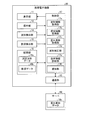
- FIG. 1 is a block diagram of a portable electronic device.
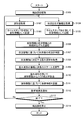
- FIG. 2 is a flowchart illustrating an example of a processing procedure of autonomic nerve diagnosis processing.
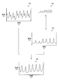
- FIG. 3 is a diagram illustrating an example of a waveform processed by the portable electronic device.
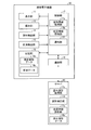
- FIG. 4 is a diagram illustrating an example of a configuration of a diagnostic system.
- FIG. 5 is a diagram illustrating another example of the configuration of the diagnostic system.
- FIG. 6 is a diagram illustrating an example of a configuration when the diagnosis process is realized using software.
- FIG. 1 is a block diagram of the portable electronic device 10.
- the mobile electronic device 10 is, for example, a mobile phone.
- the portable electronic device 10 has a function of diagnosing a user's autonomic nerve.
- the mobile electronic device 10 includes a display unit 11, an operation unit 12, a communication unit 13, a waveform detection unit 14, a situation detection unit 15, a storage unit 16, and a control unit 17. Including.
- the display unit 11 includes a display device such as a liquid crystal display (LCD: Liquid Crystal Display), an organic EL panel display (OELD: Organic Electro-Luminescence Display), or an inorganic EL panel display (IELD: Inorganic Electro-Luminescence Display).
- LCD Liquid Crystal Display
- OELD Organic Electro-Luminescence Display
- IELD Inorganic Electro-Luminescence Display
- the display unit 11 displays a screen including characters, images, symbols, graphics, and the like.
- the operation unit 12 receives user operations.
- the operation unit 12 includes input devices such as buttons, keys, and a touch screen in order to accept operations.
- the operation unit 12 may be formed integrally with the display unit 11 like a touch screen display.
- the communication unit 13 communicates wirelessly.
- the communication unit 13 supports, for example, cellular phone communication such as 2G, 3G, and 4G.
- the communication unit 13 may support a plurality of communication methods.
- the communication unit 13 may support a short-distance communication method such as IEEE 802.11 or Bluetooth (registered trademark).
- the waveform detector 14 detects a waveform for diagnosing the autonomic nerve of the user carrying the mobile electronic device 10.
- the waveform for diagnosing the user's autonomic nerve includes, for example, a waveform of a pulse wave, a waveform indicating fluctuations in heart rate, and the like.
- the waveform detection unit 14 can include various sensors.
- the waveform detector 14 can include, for example, a camera (image sensor).
- the waveform detector 14 may include, for example, a small heart rate sensor or a photoelectric pulse wave meter.
- the waveform detector 14 may include sensors other than these.
- the waveform detection unit 14 may include a plurality of sensors that detect waveforms, and may be configured to select an optimal waveform according to the situation.
- the sensor included in the waveform detection unit 14 may be used for purposes other than the diagnosis of the user's autonomic nerve. In other words, a configuration in which the sensor provided for the portable electronic device 10 for other uses is also used as the waveform detection unit 14 may be used. In the following description, it is assumed that a waveform of a pulse wave is used as a waveform for diagnosing the user's autonomic nerve.
- the status detection unit 15 detects the status of the user who is carrying the mobile electronic device 10.
- the situation detection unit 15 can include various sensors.
- the situation detection unit 15 can include an acceleration sensor.
- the direction and magnitude of acceleration applied to the user can be detected by the acceleration sensor. Furthermore, by analyzing the direction and magnitude of the acceleration, it is possible to estimate the movement status of the user, the magnitude of vibration felt by the user, and the like.
- the estimated movement state includes a stationary state, a walking state, a running state, a state of riding a vehicle, and the like.
- the status detection unit 15 can include a barometer.
- a barometer can detect a change in atmospheric pressure around the user. The change in atmospheric pressure can be used to estimate the altitude of the user's current location. By combining the acceleration sensor and the barometer, it is possible to estimate the state in which the user is climbing the hill, the state in which the user is descending the hill, and the like, and the accuracy of estimation of the movement situation is improved.
- the status detection unit 15 can include a GPS (Global Positioning System) receiver.
- the current position of the user can be detected by the GPS receiver.
- By comparing the current position with the map data it is possible to estimate with high accuracy what kind of environment the user is in.
- By combining an acceleration sensor and a GPS receiver it is possible to determine whether the user's travel route is along a road or along a railway line, and the type of vehicle can be specified. The accuracy of situation estimation is improved.
- the status detection unit 15 can include an illuminance sensor. The brightness around the user can be detected by the illuminance sensor.
- the situation detection unit 15 can include a temperature sensor. The temperature around the user can be detected by the temperature sensor.
- the situation detection unit 15 can include a capacitive touch sensor. The capacitance type sensor can detect the capacitance of the user's body. The magnitude of the capacitance can be used to estimate the user's tension.
- the status detection unit 15 may include other sensors.
- the situation detection unit 15 may include a plurality of sensors.
- the sensor included in the situation detection unit 15 may be used for purposes other than diagnosis of the user's autonomic nerve. In other words, a configuration in which the sensor provided for the portable electronic device 10 for other uses is also used as the situation detection unit 15 may be used.
- the storage unit 16 stores programs and data.
- the storage unit 16 is also used as a work area for temporarily storing the processing result of the control unit 17.
- the storage unit 16 may include any non-transitory storage medium such as a semiconductor storage medium and a magnetic storage medium.
- the storage unit 16 may include a plurality of types of storage media.
- the storage unit 16 may include a combination of a portable non-transitory storage medium such as a memory card, an optical disk, or a magneto-optical disk, and a storage medium reader.
- the storage unit 16 may include a storage device used as a temporary storage area such as a RAM (Random Access Memory).
- the data stored in the storage unit 16 includes measurement waveform data 16a, status data 16b, and distortion waveform data 16c.
- the waveform detected by the waveform detector 14 is recorded as waveform information.
- the status data 16b information indicating the status of the user detected by the status detection unit 15 is recorded as status information.
- a time stamp indicating the detected time is added to the waveform information recorded in the measurement waveform data 16a and the situation information recorded in the situation data 16b so that both information can be processed in synchronization.
- the distortion waveform data 16c stores a distortion waveform (hereinafter also referred to as “distortion waveform”) caused by the situation in association with the situation information indicating the situation of the user.
- the distortion waveform is a difference between a waveform that should be detected originally and a waveform that has changed under the influence of the situation.
- the distortion waveform is a noise component (distortion component) that hinders improving the accuracy of autonomic nerve diagnosis.
- the combination of the status information and the distortion waveform is stored in advance in the distortion waveform data 16c.
- the combination of the situation information and the distortion waveform can be obtained, for example, by comparing waveforms detected from the subject under various situations.
- the distortion waveform data 16c may be configured such that the distortion waveform is associated with a plurality of types of situation information detected under the same situation during the same period.
- the control unit 17 comprehensively controls the mobile electronic device 10.
- the control unit 17 performs various controls for the portable electronic device 10 to exhibit its functions.
- the control unit 17 includes an arithmetic processing device.
- the arithmetic processing unit is, for example, a CPU (Central Processing Unit), an SoC (System-on-a-chip), an MCU (Micro Control Unit), or an FPGA (Field-Programmable Gate Array).
- the control unit 17 includes a waveform information acquisition unit 17a, a situation information acquisition unit 17b, a distortion waveform acquisition unit 17c, a waveform correction unit 17d, an autonomic nerve diagnosis unit 17e, and a notification unit 17f.
- the waveform information acquisition unit 17a acquires the waveform detected by the waveform detection unit 14, adds a time stamp, and records the waveform information in the measurement waveform data 16a.
- the status information acquisition unit 17b acquires information indicating the status of the user from the status detection unit 15, adds a time stamp, and records it as status information in the status data 16b.
- the situation information acquisition unit 17b may record the information acquired from the situation detection unit 15 as the situation information as it is, or may record information obtained by analyzing the information acquired from the situation detection unit 15 as the situation information. .
- a case where the situation detection unit 15 includes an acceleration sensor will be described as an example. When the information is recorded as it is, the direction and magnitude of the acceleration are recorded as the situation information. On the other hand, when recording information obtained by analyzing information, the movement status of the user estimated based on the direction and magnitude of acceleration is recorded as status information.
- the distortion waveform acquisition unit 17c acquires a distortion waveform corresponding to the specified situation information from the distortion waveform data 16c.
- the distortion waveform acquisition unit 17c obtains the situation information closest to the designated situation information from the situation information stored in the distortion waveform data 16c in order to obtain the distortion waveform corresponding to the designated situation information. Identify.
- the distortion waveform acquisition part 17c acquires the distortion waveform matched with the specified condition information from the distortion waveform data 16c.
- the situation information that is most approximate is specified by using a statistical method such as a moving average method.
- the distortion waveform acquisition unit 17c determines the priority for each type of situation information, and determines the priority of the situation information that is closest to the specified situation information. May be specified. For example, a method may be used in which the degree of approximation is evaluated in order from the type of status information with the highest priority, and the combinations of the status information and the distortion waveform are narrowed down. Alternatively, a total approximate value of the combination of the situation information and the distortion waveform is calculated by summing a value obtained by multiplying the degree of approximation evaluated for each situation information and the weight determined for each priority of the situation information. A method may be used.
- the waveform correction unit 17d corrects the waveform indicated by the waveform information included in the measurement waveform data 16a using the distortion waveform acquired by the distortion waveform acquisition unit 17c. By the correction using the distortion waveform, it is possible to remove the noise component caused by the user's situation from the waveform information included in the measurement waveform data 16a. Thereby, the accuracy of the autonomic nerve diagnosis based on the waveform information can be improved.
- the waveform correction unit 17d corrects the waveform by waveform separation. Specifically, the waveform correction unit 17d corrects the waveform information by subtracting the distortion waveform from the waveform indicated by the waveform information included in the measurement waveform data 16a.
- the waveform correction unit 17d adjusts the amplitude and wavelength scale of the distortion waveform so as to match the waveform scale indicated by the waveform information included in the measurement waveform data 16a.
- the type of sensor included in the waveform detector 14 and the type of sensor used to obtain the distortion waveform are not necessarily the same, and the subject and the user of the portable electronic device 10 for obtaining the distortion waveform are not necessarily the same person. is not. For this reason, the scale of the amplitude and wavelength of the distortion waveform may not match the waveform scale indicated by the waveform information included in the measurement waveform data 16a.
- the waveform correction unit 17d uses, for example, a predetermined coefficient in order to adjust the scale of the amplitude of the distortion waveform.
- the coefficient is determined based on a difference in sensor sensitivity, a difference in sensor output level, and the like.
- the waveform correcting unit 17d calculates a singular point of the distorted waveform and a singular point of the waveform included in the measured waveform data 16a in order to adjust the wavelength scale of the distorted waveform.
- the singular point can be calculated using, for example, Fourier transform, fast Fourier transform, wavelet transform, or the like.
- the waveform correction unit 17d adjusts the wavelength scale of the distortion waveform so that the singular point of the distortion waveform and the singular point of the waveform included in the measurement waveform data 16a most closely match.
- the autonomic nerve diagnosis unit 17e diagnoses the user's autonomic nerve based on the waveform information corrected by the waveform correction unit 17d.
- a method for diagnosing the autonomic nerve based on the waveform information various known methods can be used.
- the notification unit 17f notifies the user of the result of diagnosis by the autonomic nerve diagnosis unit 17e.
- the notification unit 17f notifies the user of the result of diagnosis by, for example, displaying on the display unit 11. Any method may be used for notifying the user of the result of diagnosis.
- the notification unit 17f may have a function of processing the autonomic nerve diagnosis result for each application application.
- the notification unit 17f can incorporate an application plug-in that the user downloads from a commercial server or the like through the communication unit 13. With this plug-in, the notification unit 17f can change the format of the diagnosis result to be displayed.
- FIG. 2 is a flowchart illustrating an example of a processing procedure of autonomic nerve diagnosis processing.
- FIG. 3 is a diagram illustrating an example of a waveform processed by the mobile electronic device 10.
- control unit 17 activates the waveform detection unit 14 and the situation detection unit 15 as step S101.
- the waveform information acquisition unit 17a acquires the waveform detected by the waveform detection unit 14 as step S102.
- the waveform information acquisition unit 17a adds a time stamp to the acquired waveform and records the waveform information in the measurement waveform data 16a.
- the status information acquisition unit 17b executes step S104 and step S105.
- the situation information acquisition part 17b acquires the information which shows a user's condition from the situation detection part 15 as step S104.
- the status information acquisition unit 17b adds a time stamp to the acquired information, and records the status information in the status data 16b.
- step S106 the waveform correction unit 17d shifts the waveform information recorded in the measurement waveform data 16a and the situation information recorded in the situation data 16b so as to obtain information of the same period. Adjust to get.
- the magnitude of the time shift is set based on a delay time from when the phenomenon to be measured occurs until the sensor outputs a signal corresponding to the phenomenon.
- step S106 waveform information indicating the waveform W1 shown in FIG. 3 is acquired.
- the situation information acquired in step S106 indicates the situation of the user during the period in which such a waveform is detected.
- the waveform W1 includes a noise component resulting from the situation indicated by the situation information.
- step S107 the waveform correction unit 17d executes a process for determining the user's situation based on the obtained situation information as necessary.
- the waveform correction unit 17d estimates the movement status of the user based on the pattern of change in the magnitude of acceleration included in the acquired status information. This processing is unnecessary when the situation information can be designated as it is when acquiring the distortion waveform from the distortion waveform data 16c.
- the waveform correction unit 17d causes the distortion waveform acquisition unit 17c to acquire a distortion waveform corresponding to the situation information (or the user situation determined based on the situation information) from the distortion waveform data 16c. .
- step S108 for example, the waveform W2 shown in FIG. 3 is acquired as a distortion waveform. Since the waveform W2 is different from the waveform W1 in amplitude and wavelength scale, the waveform W2 cannot be used to remove noise components from the waveform W1.
- the waveform correction unit 17d adjusts the amplitude and wavelength scale of the acquired distortion waveform in step S109.
- step S109 for example, the waveform W3 is obtained by adjusting the amplitude and wavelength scale of the waveform W2 shown in FIG.
- the singular point of the waveform W1 and the singular point of the waveform W2 are matched. Such adjustment allows the waveform W2 to be used to remove the noise component.
- the waveform correcting unit 17d removes a noise component from the waveform information using the adjusted distortion waveform. For example, the waveform correction unit 17d divides the waveform W3 shown in FIG. 3 from the waveform W1 shown in FIG. 3 to obtain a waveform W4 from which noise components due to the situation have been removed.
- the autonomic nerve diagnosis unit 17e diagnoses the user's autonomic nerve based on the waveform information from which the noise component has been removed in step S111, and the notification unit 17f notifies the user of the diagnosis result in step S112. To do.
- control unit 17 determines whether or not to end the diagnosis process as step S113.
- diagnosis process is not terminated (No at Step S113)
- control unit 17 re-executes Step S102 and Step S104 and subsequent steps.
- ending the diagnosis process step S113, Yes
- the control unit 17 stops the waveform detection unit 14 and the situation detection unit 15 as step S114.
- steps S102 to S113 are executed, for example, at a cycle of 1 second.
- steps S102 to S103 and steps S104 to S105 are continuously executed, and steps S106 to S113 are executed at a predetermined timing.
- the mobile electronic device 10 removes noise components caused by the user's situation at the time of detection from the waveform detected by the user in order to diagnose the autonomic nerve. For this reason, the portable electronic device 10 can improve the accuracy of the autonomic nerve diagnosis.
- the mobile electronic device 10 may be configured to be expandable. Specifically, the mobile electronic device 10 can add an arbitrary sensor, and the waveform information acquisition unit 17a or the situation information acquisition unit 17b acquires information detected by the added sensor as waveform information or situation information. It may be configured.
- the portable electronic device 10 may be configured such that the user can change various filtering coefficients, threshold values, and the like used in the diagnostic processing.
- a part of the portable electronic device 10 may be arranged on a server to constitute a system including the server and the portable electronic device 10.
- FIG. 4 is a diagram showing an example of the configuration of the diagnostic system.
- the diagnostic system shown in FIG. 4 includes a portable electronic device 20 and a server 90.
- the server 90 stores the distortion waveform data 16c.
- the portable electronic device 20 has the same configuration as the portable electronic device 10 except that the distortion waveform data 16c stored in the server 90 is accessed through communication by the communication unit 13. Even with such a configuration, the same effect as the portable electronic device 10 can be obtained.
- the storage area of the storage unit 16 can be used for other purposes. Further, in the configuration shown in FIG. 4, since the distortion waveform data 16c is centrally managed in the server 90, the addition and correction of the distortion waveform can be easily performed.
- FIG. 5 is a diagram showing another example of the configuration of the diagnostic system.
- the diagnostic system shown in FIG. 5 includes a portable electronic device 30 and a server 90.
- the server 90 stores the distortion waveform data 16c and has functions of a distortion waveform acquisition unit 17c, a waveform correction unit 17d, and an autonomic nerve diagnosis unit 17e.
- the portable electronic device 30 does not store the distortion waveform data 16c, and is the same as the portable electronic device 10 except that it does not include the distortion waveform acquisition unit 17c, the waveform correction unit 17d, and the autonomic nerve diagnosis unit 17e. It has a configuration.
- the portable electronic device 30 transmits the measurement waveform data 16 a and the status data 16 b to the server 90 through communication by the communication unit 13.
- the server 90 executes a diagnostic process using the transmitted measurement waveform data 16a and status data 16b, and returns a result to the portable electronic device 30.
- the portable electronic device 30 notifies the user of the answered response. Even with such a configuration, the same effect as the portable electronic device 10 can be obtained.
- the server 90 since the main part of the diagnostic processing is executed by the server 90, the load on the portable electronic device 30 can be reduced. Furthermore, since the server 90 has a part for executing the main part of the diagnostic process, it is possible to easily implement a modification of the diagnostic process and a function addition.
- FIG. 6 is a diagram illustrating an example of a configuration when the diagnosis process is realized using software.
- the portable electronic device 40 shown in FIG. 6 has the same configuration as the portable electronic device 10 except that the storage unit 16 stores the diagnostic program 16d.
- the function of the waveform information acquisition unit 17a, the situation information acquisition unit 17b, the distortion waveform acquisition unit 17c, the waveform correction unit 17d, the autonomic nerve diagnosis unit 17e, and the notification unit 17f This is realized by executing the diagnostic program 16d using the apparatus. Even with such a configuration, the same effect as the portable electronic device 10 can be obtained.
- the diagnostic program 16d may be downloaded from another device.
- the diagnostic program 16d may be stored in a portable non-transitory storage medium.
- the portable electronic device 40 may be configured to execute a program other than the diagnostic program 16d using an arithmetic processing device.
- Programs other than the diagnostic program 16d include, for example, an SNS (Social Networking Service) program, a mail program, a schedule management program, a browser program, and the like.
- SNS Social Networking Service
- the status information acquisition unit 17b may acquire status information indicating the status of the user by monitoring the program being executed.
- the situation information acquisition unit 17b may extract information indicating the situation of the user from a message transmitted by the user using an SNS program or a mail program. For example, the situation information acquisition unit 17b extracts information about a meal that is being eaten from a message and records it as situation information.
- the status information acquisition unit 17b may extract information indicating the status of the user from the schedule registered by the user using the schedule management program. For example, the status information acquisition unit 17b records, as status information, that the user is visiting a customer company based on a registered schedule.
- the status information acquisition unit 17b may acquire information indicating the status of the user based on the WEB page that the user is browsing using the browser program. For example, the status information acquisition unit 17b determines the type of the WEB page by comparing the address of the WEB page being browsed with a database, and records the type of the WEB page as the status information.
- a mobile phone has been described as an example of the mobile electronic device, but the device according to the appended claims is not limited to the mobile phone.
- the device according to the appended claims may be, for example, a smartphone, a tablet, a portable personal computer, a digital camera, a media player, an electronic book reader, a navigator, or a game machine.
Landscapes
- Health & Medical Sciences (AREA)
- Life Sciences & Earth Sciences (AREA)
- Engineering & Computer Science (AREA)
- Molecular Biology (AREA)
- Animal Behavior & Ethology (AREA)
- Veterinary Medicine (AREA)
- Public Health (AREA)
- Physics & Mathematics (AREA)
- General Health & Medical Sciences (AREA)
- Biophysics (AREA)
- Pathology (AREA)
- Biomedical Technology (AREA)
- Heart & Thoracic Surgery (AREA)
- Medical Informatics (AREA)
- Surgery (AREA)
- Signal Processing (AREA)
- Physiology (AREA)
- Neurology (AREA)
- Computer Vision & Pattern Recognition (AREA)
- Psychiatry (AREA)
- Artificial Intelligence (AREA)
- Cardiology (AREA)
- Neurosurgery (AREA)
- Multimedia (AREA)
- Measuring Pulse, Heart Rate, Blood Pressure Or Blood Flow (AREA)
- Measurement Of The Respiration, Hearing Ability, Form, And Blood Characteristics Of Living Organisms (AREA)
- Measuring And Recording Apparatus For Diagnosis (AREA)
- Measurement And Recording Of Electrical Phenomena And Electrical Characteristics Of The Living Body (AREA)
Abstract
携帯電子機器(10)は、利用者から検出された波形にタイムスタンプを付加して波形情報として記録する波形情報取得部(17a)と、利用者の状況を示す情報にタイムスタンプを付加して状況情報として記録する状況情報取得部(17b)と、状況と歪み波形とが対応付けて格納されている歪み波形データ(16c)から、波形情報と同じ期間における状況情報が示す状況に対応する歪み波形を取得する歪み波形取得部(17c)と、歪み波形を用いて波形情報を補正する波形補正部(17d)と、波形補正部(17d)によって補正された波形情報を用いて利用者の自律神経を診断する自律神経診断部(17e)とを備える。
Description
本出願は、携帯電子機器、診断方法、および診断プログラムに関する。
身体の状態を検出又は診断するための各種技術が知られている。例えば、特許文献1は、カメラのレンズに指を置いて撮影された入力画像に基づいて脈波を算出する技術を開示している。特許文献2は、被験者の脈波データから不整脈等によるノイズを除去して、自律神経等の診断に用いる技術を開示している。
自律神経を診断する場合、自律神経は様々な要因の影響を受けやすいために、正確な診断が難しい。特に、携帯電子機器を用いて移動中の利用者の自律神経を診断しようとすると、状況の変化が大きいために正確な診断が難しい。このような理由から、自律神経の診断の精度を向上させることができる携帯電子機器、診断方法、および診断プログラムに関するニーズがある。
1つの態様に係る携帯電子機器は、利用者から検出された波形にタイムスタンプを付加して波形情報として記録する波形情報取得部と、前記利用者の状況を示す情報にタイムスタンプを付加して状況情報として記録する状況情報取得部と、状況と歪み波形とが対応付けて格納されている歪み波形データから、前記波形情報と同じ期間における前記状況情報が示す状況に対応する前記歪み波形を取得する歪み波形取得部と、前記歪み波形を用いて前記波形情報を補正する波形補正部と、前記波形補正部によって補正された前記波形情報を用いて前記利用者の自律神経を診断する自律神経診断部とを備える。
1つの態様に係る診断方法は、利用者から検出された波形にタイムスタンプを付加して波形情報として記録するステップと、前記利用者の状況を示す情報にタイムスタンプを付加して状況情報として記録するステップと、状況と歪み波形とが対応付けて格納されている歪み波形データから、前記波形情報と同じ期間における前記状況情報が示す状況に対応する前記歪み波形を取得するステップと、前記歪み波形を用いて前記波形情報を補正するステップと、補正された前記波形情報を用いて前記利用者の自律神経を診断するステップとを含む。
1つの態様に係る診断プログラムは、携帯電子機器に、利用者から検出された波形にタイムスタンプを付加して波形情報として記録するステップと、前記利用者の状況を示す情報にタイムスタンプを付加して状況情報として記録するステップと、状況と歪み波形とが対応付けて格納されている歪み波形データから、前記波形情報と同じ期間における前記状況情報が示す状況に対応する前記歪み波形を取得するステップと、前記歪み波形を用いて前記波形情報を補正するステップと、補正された前記波形情報を用いて前記利用者の自律神経を診断するステップとを実行させる。
本発明を実施するための実施形態を、図面を参照しつつ詳細に説明する。
図1を参照しながら、実施形態に係る携帯電子機器10の構成について説明する。図1は、携帯電子機器10のブロック図である。携帯電子機器10は、例えば、携帯電話機である。携帯電子機器10は、利用者の自律神経を診断する機能を有する。図1に示すように、携帯電子機器10は、表示部11と、操作部12と、通信部13と、波形検出部14と、状況検出部15と、記憶部16と、制御部17とを含む。
表示部11は、液晶ディスプレイ(LCD:Liquid Crystal Display)、有機ELパネルディスプレイ(OELD:Organic Electro-Luminescence Display)、又は無機ELパネルディスプレイ(IELD:Inorganic Electro-Luminescence Display)等の表示デバイスを備える。表示部11は、文字、画像、記号、及び図形等を含む画面を表示する。
操作部12は、利用者の操作を受け付ける。操作部12は、操作を受け付けるために、ボタン、キー、タッチスクリーン等の入力デバイスを備える。操作部12は、タッチスクリーンディスプレイのように、表示部11と一体に形成されていてもよい。
通信部13は、無線により通信する。通信部13は、例えば、2G、3G、4G等のセルラーフォンの通信をサポートする。通信部13は、複数の通信方式をサポートしてもよい。通信部13は、IEEE802.11、Bluetooth(登録商標)等の近距離での通信方式をサポートしてもよい。
波形検出部14は、携帯電子機器10を携帯している利用者の自律神経を診断するための波形を検出する。利用者の自律神経を診断するための波形は、例えば、脈波の波形、心拍数の変動を示す波形等を含む。
波形検出部14は、各種のセンサを含むことができる。利用者の自律神経を診断するための波形として脈波の波形が用いられる場合、波形検出部14は、例えば、カメラ(イメージセンサ)を含むことができる。利用者の自律神経を診断するための波形として心拍数の変動を示す波形が用いられる場合、波形検出部14は、例えば、小型の心拍センサ又は光電脈波計を含むことができる。
波形検出部14は、これら以外のセンサを含んでもよい。波形検出部14は、波形を検出する複数のセンサを含み、状況に応じて最適な波形を選択することができるように構成されてもよい。波形検出部14が含むセンサは、利用者の自律神経の診断以外の用途に用いられてよい。換言すると、携帯電子機器10が他の用途のために備えているセンサを、波形検出部14としても利用する構成であってもよい。以下の説明では、利用者の自律神経を診断するための波形として脈波の波形が用いられるものと想定する。
状況検出部15は、携帯電子機器10を携帯している利用者の状況を検出する。状況検出部15は、各種のセンサを含むことができる。
状況検出部15は、加速度センサを含むことができる。加速度センサにより、利用者に加わっている加速度の方向及び大きさを検出することができる。さらに、加速度の方向及び大きさを分析することにより、利用者の移動状況、利用者が感じている振動の大きさ等を推定することができる。推定可能な移動状況には、静止している状態、歩いている状態、走っている状態、乗り物に乗っている状態等が含まれる。
状況検出部15は、気圧計を含むことができる。気圧計により、利用者の周囲の気圧の変化を検出することができる。気圧の変化は、利用者の現在地の高度を推定するために用いることができる。加速度センサと気圧計を組み合わせることにより、利用者が坂を上っている状態、利用者が坂を下りている状態等を推定することが可能になり、移動状況の推定の精度が向上する。
状況検出部15は、GPS(Global Positioning System)レシーバを含むことができる。GPSレシーバにより、利用者の現在位置を検出することができる。現在位置を地図データと照合することにより、利用者がどのような環境にいるかを高い精度で推定することができる。加速度センサとGPSレシーバを組み合わせることにより、利用者の移動経路が、道路に沿っているのか、鉄道路線に沿っているのか等を判定して、乗り物の種類を特定することが可能になり、移動状況の推定の精度が向上する。
状況検出部15は、照度センサを含むことができる。照度センサにより、利用者の周囲の明るさを検出することができる。状況検出部15は、温度センサを含むことができる。温度センサにより、利用者の周囲の温度を検出することができる。状況検出部15は、静電容量式タッチセンサを含むことができる。静電容量式タッチセンサにより、利用者の身体の静電容量の大きさを検出することができる。静電容量の大きさは、利用者の緊張度を推定するために用いることができる。
状況検出部15は、これら以外のセンサを含んでもよい。状況検出部15は、複数のセンサを含んでもよい。状況検出部15が含むセンサは、利用者の自律神経の診断以外の用途に用いられてもよい。換言すると、携帯電子機器10が他の用途のために備えているセンサを、状況検出部15としても利用する構成であってもよい。
記憶部16は、プログラム及びデータを記憶する。記憶部16は、制御部17の処理結果を一時的に記憶する作業領域としても利用される。記憶部16は、半導体記憶媒体、及び磁気記憶媒体等の任意の非一過的(non-transitory)な記憶媒体を含んでよい。記憶部16は、複数の種類の記憶媒体を含んでよい。記憶部16は、メモリカード、光ディスク、又は光磁気ディスク等の可搬の非一過的な記憶媒体と、記憶媒体の読み取り装置との組み合わせを含んでよい。記憶部16は、RAM(Random Access Memory)等の一時的な記憶領域として利用される記憶デバイスを含んでよい。
記憶部16に記憶されるデータは、測定波形データ16aと、状況データ16bと、歪み波形データ16cとを含む。測定波形データ16aには、波形検出部14によって検出された波形が波形情報として記録される。状況データ16bには、状況検出部15によって検出された利用者の状況を示す情報が状況情報として記録される。測定波形データ16aに記録される波形情報及び状況データ16bに記録される状況情報には、両者の情報を同期させて処理することが可能なように、検出された時間を示すタイムスタンプが付加される。
歪み波形データ16cは、利用者の状況を示す状況情報と対応付けて、その状況に起因する歪み(artifact)の波形(以下、「歪み波形」ともいう)を記憶する。歪み波形は、本来検出されるべき波形と、状況の影響を受けて変動した波形との差分である。換言すると、歪み波形は、自律神経の診断の精度を向上させることを阻害するノイズ成分(歪み成分)である。
状況情報と歪み波形との組み合わせは、歪み波形データ16cに予め格納される。状況情報と歪み波形との組み合わせは、例えば、様々な状況下で被験者から検出した波形を比較することによって得ることができる。
歪み波形データ16cは、歪み波形が、同じ期間に同じ状況下で検出された複数種類の状況情報と対応付けられるように構成されてもよい。
制御部17は、携帯電子機器10を統括的に制御する。制御部17は、携帯電子機器10がその機能を発揮するための各種制御を行う。制御部17は、演算処理装置を有する。演算処理装置は、例えば、CPU(Central Processing Unit)、SoC(System-on-a-chip)、MCU(Micro Control Unit)、又はFPGA(Field-Programmable Gate Array)である。
制御部17は、波形情報取得部17aと、状況情報取得部17bと、歪み波形取得部17cと、波形補正部17dと、自律神経診断部17eと、通知部17fとを有する。波形情報取得部17aは、波形検出部14によって検出される波形を取得し、タイムスタンプを付加して測定波形データ16aに波形情報として記録する。
状況情報取得部17bは、状況検出部15から利用者の状況を示す情報を取得し、タイムスタンプを付加して状況データ16bに状況情報として記録する。状況情報取得部17bは、状況検出部15から取得した情報をそのまま状況情報として記録してもよいし、状況検出部15から取得した情報の分析により得た情報を状況情報として記録してもよい。状況検出部15が加速度センサを含む場合を例にして説明する。情報をそのまま記録する場合、加速度の方向及び大きさが状況情報として記録される。一方、情報の分析により得た情報を記録する場合、加速度の方向及び大きさに基づいて推定される利用者の移動状況が状況情報として記録される。
歪み波形取得部17cは、指定された状況情報に対応する歪み波形を歪み波形データ16cから取得する。歪み波形取得部17cは、指定された状況情報に対応する歪み波形を取得するために、歪み波形データ16cに格納されている状況情報の中から、指定された状況情報に最も近似する状況情報を特定する。そして、歪み波形取得部17cは、特定した状況情報に対応付けられた歪み波形を歪み波形データ16cから取得する。最も近似する状況情報の特定は、例えば、移動平均法等の統計的な手法を用いて実現される。
歪み波形が複数種類の状況情報と対応付けられている場合、歪み波形取得部17cは、状況情報の種類ごとに優先度を定め、指定された状況情報に最も近似する状況情報を、優先度を用いて特定してもよい。例えば、優先度の高い種類の状況情報から順に近似度を評価して、状況情報と歪み波形の組み合わせを絞り込んでいく方式を用いてもよい。あるいは、状況情報毎に評価した近似度と、状況情報の優先度毎に定められた重みとを乗じた値を合計することによって、状況情報と歪み波形の組み合わせの総合的な近似値を算出する方式を用いてもよい。
波形補正部17dは、測定波形データ16aに含まれる波形情報が示す波形を、歪み波形取得部17cによって取得された歪み波形を用いて補正する。歪み波形を用いた補正により、測定波形データ16aに含まれる波形情報から、利用者の状況に起因するノイズ成分を除去することができる。これにより、波形情報に基づく自律神経の診断の精度を向上させることができる。
波形補正部17dは、波形分離によって波形を補正する。具体的には、波形補正部17dは、測定波形データ16aに含まれる波形情報が示す波形から歪み波形を減算することによって波形情報を補正する。
歪み波形を用いた補正に先立って、波形補正部17dは、歪み波形の振幅と波長のスケールを、測定波形データ16aに含まれる波形情報が示す波形のスケールに合うように調整する。波形検出部14に含まれるセンサの種類と歪み波形を得るために用いられたセンサの種類とは必ずしも同一ではなく、歪み波形を得るための被験者と携帯電子機器10の利用者とは必ずしも同一人物ではない。このため、歪み波形の振幅と波長のスケールと、測定波形データ16aに含まれる波形情報が示す波形のスケールとが一致していないことがある。
波形補正部17dは、歪み波形の振幅のスケールを調整するために、例えば、予め定められた係数を用いる。係数は、センサの感度の相違、センサの出力レベルの相違等に基づいて決定される。
波形補正部17dは、歪み波形の波長のスケールを調整するために、歪み波形の特異点と、測定波形データ16aに含まれる波形の特異点とを算出する。特異点は、例えば、フーリエ変換、高速フーリエ変換、ウェーブレット変換等を用いて算出することができる。波形補正部17dは、歪み波形の特異点と測定波形データ16aに含まれる波形の特異点とが最もマッチするように、歪み波形の波長のスケールを調整する。
自律神経診断部17eは、波形補正部17dによって補正された波形情報に基づいて、利用者の自律神経を診断する。波形情報に基づいて自律神経を診断するための手法については、公知の各種の手法を用いることができる。
通知部17fは、自律神経診断部17eによる診断の結果を利用者に通知する。通知部17fは、例えば、表示部11への表示によって、診断の結果を利用者に通知する。診断の結果を利用者に通知する方式は、いかなる方式であってもよい。通知部17fは、自律神経の診断結果をアプリケーション用途毎に加工する機能を有していてもよい。例えば、通知部17fは、ユーザーが通信部13を通して商用サーバ等からダウンロードするアプリケーション用プラグイン等を組み込むことができる。このプラグインによって、通知部17fは、表示する診断結果の様式等を変化させることができる。
図2及び図3を参照しながら、携帯電子機器10による自律神経の診断処理について説明する。図2は、自律神経の診断処理の処理手順の例を示すフローチャートである。図3は、携帯電子機器10によって処理される波形の例を示す図である。
図2に示すように、制御部17は、ステップS101として、波形検出部14及び状況検出部15を起動する。
続いて、波形情報取得部17aは、ステップS102として、波形検出部14によって検出される波形を取得する。波形情報取得部17aは、ステップS103として、取得した波形にタイムスタンプを付加して、波形情報として測定波形データ16aに記録する。
ステップS102及びステップS103と並行して、状況情報取得部17bは、ステップS104及びステップS105を実行する。状況情報取得部17bは、ステップS104として、状況検出部15から利用者の状況を示す情報を取得する。状況情報取得部17bは、ステップS105として、取得した情報にタイムスタンプを付加して、状況情報として状況データ16bに記録する。
波形補正部17dは、ステップS106として、測定波形データ16aに記録されている波形情報と、状況データ16bに記録されている状況情報とを、同じ期間の情報が取得されるように時間的なずれを調整して取得する。時間的なずれの大きさは、測定対象の現象が生じてから、センサがその現象に応じた信号を出力するまでの遅延時間に基づいて設定される。
ステップS106では、例えば、図3に示す波形W1を示す波形情報が取得される。ステップS106で取得される状況情報は、このような波形が検出された期間における利用者の状況を示す。波形W1は、状況情報が示す状況に起因するノイズ成分を含んでいる。
続いて、波形補正部17dは、ステップS107として、取得した状況情報に基づいて利用者の状況を判定する処理を、必要に応じて実行する。例えば、波形補正部17dは、取得した状況情報に含まれる加速度の大きさの変化のパターンに基づいて、利用者の移動状況を推定する。この処理は、歪み波形データ16cから歪み波形を取得する際に状況情報をそのまま指定できる場合には不要である。
続いて、波形補正部17dは、ステップS108として、歪み波形取得部17cに、状況情報(又は状況情報に基づいて判定された利用者の状況)に対応する歪み波形を歪み波形データ16cから取得させる。
ステップS108では、例えば、図3に示す波形W2が歪み波形として取得される。波形W2は、振幅及び波長のスケールが波形W1と異なるため、このままでは、波形W1からノイズ成分を除去するために用いることはできない。
波形補正部17dは、ステップS109として、取得された歪み波形の振幅及び波長のスケールを調整する。ステップS109では、例えば、図3に示す波形W2の振幅及び波長のスケールを調整することによって、波形W3が得られる。波形W2の振幅を調整するために、波形W1の特異点と波形W2の特異点とがマッチングされる。このような調整により、ノイズ成分を除去するために波形W2を用いることが可能になる。
続いて、波形補正部17dが、ステップS110として、調整された歪み波形を用いて、波形情報からノイズ成分を除去する。波形補正部17dは、例えば、図3に示す波形W1から、図3に示す波形W3を除算することにより、状況に起因するノイズ成分が除去された波形W4を得る。
続いて、自律神経診断部17eが、ステップS111として、ノイズ成分が除去された波形情報に基づいて利用者の自律神経を診断し、通知部17fが、ステップS112として、診断結果を利用者に通知する。
その後、制御部17は、ステップS113として、診断処理を終了するか判定する。診断処理を終了しない場合(ステップS113,No)、制御部17は、ステップS102及びステップS104以降を再実行させる。診断処理を終了する場合(ステップS113,Yes)、制御部17は、ステップS114として、波形検出部14及び状況検出部15を停止する。
図2に示す診断処理は、リアルタイムで実行されてもよいし、バッチ的に実行されてもよい。リアルタイムで実行される場合、ステップS102~ステップS113が、例えば、1秒周期で実行される。バッチ的に実行される場合、ステップS102~ステップS103及びステップS104~ステップS105が継続的に実行され、所定のタイミングでステップS106~ステップS113が実行される。
上述したように、携帯電子機器10は、自律神経を診断するために利用者から検出された波形から、検出時における利用者の状況に起因するノイズ成分を除去する。このため、携帯電子機器10は、自律神経の診断の精度を向上させることができる。
本出願の開示する実施形態は、発明の要旨および範囲を逸脱しない範囲で変更することができる。さらに、本出願の開示する実施形態およびその変形例は、適宜組み合わせることができる。例えば、上記の実施形態は、以下のように変形してもよい。
例えば、携帯電子機器10は、拡張可能に構成されてもよい。具体的には、携帯電子機器10は、任意のセンサを追加可能で、追加されたセンサが検出する情報を波形情報又は状況情報として波形情報取得部17a又は状況情報取得部17bが取得するように構成されてもよい。
携帯電子機器10は、診断処理において用いられる各種のフィルタリング係数、閾値等を利用者が変更可能に構成されてもよい。
上記の実施形態において説明した装置の構成は、適宜、分散または集約してもよい。携帯電子機器10の一部をサーバに配して、サーバと携帯電子機器10とを含むシステムを構成してもよい。
図4は、診断システムの構成の例を示す図である。図4に示す診断システムは、携帯電子機器20と、サーバ90とを含む。サーバ90は、歪み波形データ16cを記憶する。携帯電子機器20は、通信部13による通信を通じて、サーバ90に記憶されている歪み波形データ16cにアクセスすることを除いて、携帯電子機器10と同様の構成を有する。このような構成によっても、携帯電子機器10と同様の効果を得ることができる。
さらに、図4に示す構成では、携帯電子機器20は、歪み波形データ16cを記憶する必要がないので、記憶部16の記憶領域を他の用途に活用することができる。さらに、図4に示す構成では、歪み波形データ16cがサーバ90において中央管理されるので、歪み波形の追加、修正等を容易に行うことができる。
図5は、診断システムの構成の他の例を示す図である。図5に示す診断システムは、携帯電子機器30と、サーバ90とを含む。サーバ90は、歪み波形データ16cを記憶するとともに、歪み波形取得部17c、波形補正部17d、及び自律神経診断部17eの機能を有する。携帯電子機器30は、歪み波形データ16cを記憶しておらず、歪み波形取得部17c、波形補正部17d、及び自律神経診断部17eを備えていないことを除いて、携帯電子機器10と同様の構成を有する。
図5に示す構成では、携帯電子機器30は、通信部13による通信を通じて、測定波形データ16a及び状況データ16bをサーバ90へ送信する。サーバ90は、送信された測定波形データ16a及び状況データ16bを用いて診断処理を実行し、結果を携帯電子機器30へ応答する。携帯電子機器30は、応答された回答を、利用者に通知する。このような構成によっても、携帯電子機器10と同様の効果を得ることができる。
さらに、図5に示す構成では、診断処理の主要部分がサーバ90によって実行されるため、携帯電子機器30の負荷を軽減することができる。さらに、診断処理の主要部分を実行する部位がサーバ90に存在するため、診断処理の改修や機能追加等を容易に実現することができる。
診断処理は、ソフトウェアを用いて実現されてもよい。図6は、診断処理をソフトウェアを用いて実現する場合の構成の例を示す図である。図6に示す携帯電子機器40は、記憶部16が診断プログラム16dを記憶することを除いて、携帯電子機器10と同様の構成を有する。
携帯電子機器40では、波形情報取得部17a、状況情報取得部17b、歪み波形取得部17c、波形補正部17d、自律神経診断部17e、及び通知部17fの機能は、制御部17が、演算処理装置を用いて診断プログラム16dを実行することによって実現される。このような構成によっても、携帯電子機器10と同様の効果を得ることができる。診断プログラム16dは、他の装置からダウンロードされてもよい。診断プログラム16dは、可搬の非一過的な記憶媒体に記憶されていてもよい。
診断処理をソフトウェアを用いて実現する場合、携帯電子機器40は、診断プログラム16d以外のプログラムを、演算処理装置を用いて実行できるように構成されてもよい。診断プログラム16d以外のプログラムには、例えば、SNS(Social Networking Service)プログラム、メールプログラム、スケジュール管理プログラム、ブラウザプログラム等が含まれる。
この場合、状況情報取得部17bは、実行されているプログラムを監視することによって、利用者の状況を示す状況情報を取得してもよい。状況情報取得部17bは、利用者が、SNSプログラム又はメールプログラムを用いて送信するメッセージから利用者の状況を示す情報を抽出してもよい。例えば、状況情報取得部17bは、食べている食事に関する情報をメッセージから抽出し、状況情報として記録する。
状況情報取得部17bは、利用者が、スケジュール管理プログラムを用いて登録したスケジュールから利用者の状況を示す情報を抽出してもよい。例えば、状況情報取得部17bは、登録されているスケジュールに基づいて、利用者が顧客企業を訪問していることを状況情報として記録する。
状況情報取得部17bは、利用者が、ブラウザプログラムを用いて閲覧しているWEBページに基づいて、利用者の状況を示す情報を取得してもよい。例えば、状況情報取得部17bは、閲覧中のWEBページのアドレスをデータベースと照合することによってWEBページの種類を判定し、WEBページの種類を状況情報として記録する。
上記の実施形態では、携帯電子機器の例として、携帯電話機について説明したが、添付の請求項に係る装置は、携帯電話機に限定されない。添付の請求項に係る装置は、例えば、スマートフォン、タブレット、携帯型パソコン、デジタルカメラ、メディアプレイヤ、電子書籍リーダ、ナビゲータ、又はゲーム機であってもよい。
添付の請求項に係る技術を完全かつ明瞭に開示するために特徴的な実施形態に関し記載してきた。しかし、添付の請求項は、上記実施形態に限定されるべきものでなく、本明細書に示した基礎的事項の範囲内で当該技術分野の当業者が創作しうるすべての変形例および代替可能な構成を具現化するように構成されるべきである。
10、20、30、40 携帯電子機器
11 表示部
12 操作部
13 通信部
14 波形検出部
15 状況検出部
16 記憶部
16a 測定波形データ
16b 状況データ
16c 歪み波形データ
16d 診断プログラム
17 制御部
17a 波形情報取得部
17b 状況情報取得部
17c 歪み波形取得部
17d 波形補正部
17e 自律神経診断部
17f 通知部
90 サーバ
11 表示部
12 操作部
13 通信部
14 波形検出部
15 状況検出部
16 記憶部
16a 測定波形データ
16b 状況データ
16c 歪み波形データ
16d 診断プログラム
17 制御部
17a 波形情報取得部
17b 状況情報取得部
17c 歪み波形取得部
17d 波形補正部
17e 自律神経診断部
17f 通知部
90 サーバ
Claims (6)
- 利用者から検出された波形にタイムスタンプを付加して波形情報として記録する波形情報取得部と、
前記利用者の状況を示す情報にタイムスタンプを付加して状況情報として記録する状況情報取得部と、
状況と歪み波形とが対応付けて格納されている歪み波形データから、前記波形情報と同じ期間における前記状況情報が示す状況に対応する前記歪み波形を取得する歪み波形取得部と、
前記歪み波形を用いて前記波形情報を補正する波形補正部と、
前記波形補正部によって補正された前記波形情報を用いて前記利用者の自律神経を診断する自律神経診断部と
を備える携帯電子機器。 - 前記波形補正部は、前記歪み波形の特異点と前記波形情報が示す波形の特異点とに基づいて、前記歪み波形の波長のスケールを前記波形情報が示す波形の波長のスケールに合わせる請求項1に記載の携帯電子機器。
- 加速度センサをさらに備え、
前記状況情報取得部は、前記加速度センサの検出する加速度の方向及び大きさ、又は前記加速度センサの検出する加速度の方向及び大きさに基づいて推定される前記利用者の移動状況を前記状況情報として記録する請求項1又は2に記載の携帯電子機器。 - プログラムを実行する演算処理装置をさらに備え、
前記状況情報取得部は、実行されている前記プログラムを監視することによって、前記利用者の状況を示す情報を取得する請求項1から3のいずれか1項に記載の携帯電子機器。 - 利用者から検出された波形にタイムスタンプを付加して波形情報として記録するステップと、
前記利用者の状況を示す情報にタイムスタンプを付加して状況情報として記録するステップと、
状況と歪み波形とが対応付けて格納されている歪み波形データから、前記波形情報と同じ期間における前記状況情報が示す状況に対応する前記歪み波形を取得するステップと、
前記歪み波形を用いて前記波形情報を補正するステップと、
補正された前記波形情報を用いて前記利用者の自律神経を診断するステップと
を含む診断方法。 - 携帯電子機器に、
利用者から検出された波形にタイムスタンプを付加して波形情報として記録するステップと、
前記利用者の状況を示す情報にタイムスタンプを付加して状況情報として記録するステップと、
状況と歪み波形とが対応付けて格納されている歪み波形データから、前記波形情報と同じ期間における前記状況情報が示す状況に対応する前記歪み波形を取得するステップと、
前記歪み波形を用いて前記波形情報を補正するステップと、
補正された前記波形情報を用いて前記利用者の自律神経を診断するステップと
を実行させる診断プログラム。
Priority Applications (2)
| Application Number | Priority Date | Filing Date | Title |
|---|---|---|---|
| EP14742733.0A EP2949267A4 (en) | 2013-01-23 | 2014-01-17 | PORTABLE ELECTRONIC DEVICE, DIAGNOSTIC PROCEDURE AND DIAGNOSTIC PROGRAM |
| US14/761,611 US9913609B2 (en) | 2013-01-23 | 2014-01-17 | Mobile electronic device, non-transitory storage medium storing diagnosis program, and diagnosis system |
Applications Claiming Priority (2)
| Application Number | Priority Date | Filing Date | Title |
|---|---|---|---|
| JP2013010299A JP6177533B2 (ja) | 2013-01-23 | 2013-01-23 | 携帯電子機器、携帯電子機器の作動方法、および診断プログラム |
| JP2013-010299 | 2013-01-23 |
Publications (1)
| Publication Number | Publication Date |
|---|---|
| WO2014115652A1 true WO2014115652A1 (ja) | 2014-07-31 |
Family
ID=51227444
Family Applications (1)
| Application Number | Title | Priority Date | Filing Date |
|---|---|---|---|
| PCT/JP2014/050799 Ceased WO2014115652A1 (ja) | 2013-01-23 | 2014-01-17 | 携帯電子機器、診断方法、および診断プログラム |
Country Status (4)
| Country | Link |
|---|---|
| US (1) | US9913609B2 (ja) |
| EP (1) | EP2949267A4 (ja) |
| JP (1) | JP6177533B2 (ja) |
| WO (1) | WO2014115652A1 (ja) |
Families Citing this family (3)
| Publication number | Priority date | Publication date | Assignee | Title |
|---|---|---|---|---|
| CN110234276B (zh) * | 2017-01-30 | 2022-05-27 | 日本电信电话株式会社 | 活动状态分析设备和方法 |
| US11953528B2 (en) * | 2019-01-11 | 2024-04-09 | Panasonic Intellectual Property Management Co., Ltd. | Diagnosis system, diagnosis method, program, and recording medium |
| JP7477283B2 (ja) * | 2019-11-13 | 2024-05-01 | アズビル株式会社 | Hartモデムおよび診断システム |
Citations (6)
| Publication number | Priority date | Publication date | Assignee | Title |
|---|---|---|---|---|
| JP2000037360A (ja) * | 1998-07-22 | 2000-02-08 | Seiko Instruments Inc | 脈波検出装置 |
| JP2008237574A (ja) * | 2007-03-27 | 2008-10-09 | Toshiba Corp | 自律神経指標を計測する装置、方法および生体情報を検出する装置 |
| JP2008253579A (ja) | 2007-04-05 | 2008-10-23 | Konica Minolta Sensing Inc | 脈波データ解析方法、システム、プログラム |
| JP2009297233A (ja) | 2008-06-12 | 2009-12-24 | Fujitsu Ltd | 脈波検出装置、脈波検出プログラムおよび脈波検出方法 |
| JP2010178983A (ja) * | 2009-02-06 | 2010-08-19 | Seiko Epson Corp | 測定装置及び測定方法 |
| JP2013233204A (ja) * | 2012-05-07 | 2013-11-21 | Nippon Telegr & Teleph Corp <Ntt> | 生体情報加工装置及びプログラム |
Family Cites Families (13)
| Publication number | Priority date | Publication date | Assignee | Title |
|---|---|---|---|---|
| US5299119A (en) * | 1989-07-06 | 1994-03-29 | Qmed, Inc. | Autonomic neuropathy detection and method of analysis |
| US6496723B1 (en) * | 1999-08-30 | 2002-12-17 | Denso Corporation | Method of obtaining information that corresponds to electrocardiogram of human body from pulse wave thereof |
| US6490480B1 (en) * | 1999-09-16 | 2002-12-03 | Eduard Lerner | Apparatus and methods for measuring autonomic nervous system function |
| JP3643564B2 (ja) * | 2002-02-19 | 2005-04-27 | コーリンメディカルテクノロジー株式会社 | 自律神経機能評価装置 |
| US7191004B2 (en) * | 2002-12-31 | 2007-03-13 | Cardiac Pacemakers, Inc. | Capture verification using an evoked response reference |
| JP4752673B2 (ja) * | 2005-10-06 | 2011-08-17 | コニカミノルタセンシング株式会社 | 脈波データ解析方法、システム、プログラム |
| EP1908402B1 (fr) * | 2006-10-06 | 2015-12-09 | ETA SA Manufacture Horlogère Suisse | Méthode et dispositif intégré de mesure d'une pulsation cardiaque |
| JP2009072417A (ja) * | 2007-09-21 | 2009-04-09 | Toshiba Corp | 生体情報処理装置及び方法 |
| EP2217338A1 (en) * | 2007-12-06 | 2010-08-18 | CSEM Centre Suisse d'Electronique et de Microtechnique SA - Recherche et Développement | Control device with a heart rate sensor and a motion sensor |
| TW201019901A (en) * | 2008-11-17 | 2010-06-01 | Univ Nat Yang Ming | Sleep analysis system and analysis method thereof |
| US9173579B2 (en) * | 2010-07-08 | 2015-11-03 | Intelomed, Inc. | System and method for characterizing circulatory blood flow |
| US20120203076A1 (en) * | 2011-02-08 | 2012-08-09 | Jean Pierre Fatta | Portable Physiological Data Monitoring Device |
| US8740806B2 (en) * | 2012-11-07 | 2014-06-03 | Somnarus Inc. | Methods for detection of respiratory effort and sleep apnea monitoring devices |
-
2013
- 2013-01-23 JP JP2013010299A patent/JP6177533B2/ja active Active
-
2014
- 2014-01-17 EP EP14742733.0A patent/EP2949267A4/en not_active Withdrawn
- 2014-01-17 US US14/761,611 patent/US9913609B2/en active Active
- 2014-01-17 WO PCT/JP2014/050799 patent/WO2014115652A1/ja not_active Ceased
Patent Citations (6)
| Publication number | Priority date | Publication date | Assignee | Title |
|---|---|---|---|---|
| JP2000037360A (ja) * | 1998-07-22 | 2000-02-08 | Seiko Instruments Inc | 脈波検出装置 |
| JP2008237574A (ja) * | 2007-03-27 | 2008-10-09 | Toshiba Corp | 自律神経指標を計測する装置、方法および生体情報を検出する装置 |
| JP2008253579A (ja) | 2007-04-05 | 2008-10-23 | Konica Minolta Sensing Inc | 脈波データ解析方法、システム、プログラム |
| JP2009297233A (ja) | 2008-06-12 | 2009-12-24 | Fujitsu Ltd | 脈波検出装置、脈波検出プログラムおよび脈波検出方法 |
| JP2010178983A (ja) * | 2009-02-06 | 2010-08-19 | Seiko Epson Corp | 測定装置及び測定方法 |
| JP2013233204A (ja) * | 2012-05-07 | 2013-11-21 | Nippon Telegr & Teleph Corp <Ntt> | 生体情報加工装置及びプログラム |
Non-Patent Citations (1)
| Title |
|---|
| See also references of EP2949267A4 * |
Also Published As
| Publication number | Publication date |
|---|---|
| EP2949267A1 (en) | 2015-12-02 |
| JP2014140470A (ja) | 2014-08-07 |
| US20150359476A1 (en) | 2015-12-17 |
| US9913609B2 (en) | 2018-03-13 |
| EP2949267A4 (en) | 2016-10-05 |
| JP6177533B2 (ja) | 2017-08-09 |
Similar Documents
| Publication | Publication Date | Title |
|---|---|---|
| Nakibly et al. | Hardware fingerprinting using HTML5 | |
| US11495112B2 (en) | Systems and methods for detecting a medical emergency event | |
| CN104246516B (zh) | 一种确定车辆加速度的方法及装置 | |
| US20150317890A1 (en) | Detecting changes in position of a device in a horizontal or vertical direction | |
| JP6019344B2 (ja) | 計測震度概算システム及び計測震度概算方法 | |
| WO2014137711A4 (en) | Method and mobile device for preventing driver distraction | |
| JPWO2017145928A1 (ja) | 検知装置および路面情報システム、並びに車両 | |
| US10165415B2 (en) | Method and apparatus for geomagnetic signal processing | |
| JP6177533B2 (ja) | 携帯電子機器、携帯電子機器の作動方法、および診断プログラム | |
| CN109141348B (zh) | 电子设备、高度测定方法以及记录介质 | |
| JP2016050868A5 (ja) | ||
| JP2021019977A (ja) | 情報処理装置、ヒヤリハット検出方法およびヒヤリハット検出システム | |
| JP2020166315A (ja) | 学習データの生成方法、トレーニング方法、予測モデル、コンピュータプログラム | |
| JP2019002845A (ja) | 電子機器、誤差補正方法及びプログラム | |
| US20120270192A1 (en) | Behavior estimation apparatus, behavior estimation method, and computer readable medium | |
| CN115950521A (zh) | 振动频率检测方法及检测装置、计算机设备及存储介质 | |
| JP6417755B2 (ja) | 電子機器、位置推定方法及びプログラム | |
| TWM410314U (en) | A status recorder for use with a sensor built in a hand held device | |
| KR101148233B1 (ko) | 영상 기반 터치강도 측정방법, 장치, 이를 위한 기록매체 및 이를 포함하는 모바일 기기 | |
| JP2018510357A (ja) | ハンドヘルド型電子デバイスを使用して経路の長さを計測するためのシステム及びその方法 | |
| JP6394223B2 (ja) | タイヤ状態評価システムおよびタイヤ状態評価方法 | |
| JP2025059661A (ja) | タイヤの接地挙動の表示方法 | |
| US20180150470A1 (en) | Information processing system, information processing device, information processing method, and storage medium | |
| JP2019114839A (ja) | 管理装置、管理方法、管理プログラム及び通信システム | |
| US20200234462A1 (en) | Information processing apparatus, information processing method, and recording medium |
Legal Events
| Date | Code | Title | Description |
|---|---|---|---|
| 121 | Ep: the epo has been informed by wipo that ep was designated in this application |
Ref document number: 14742733 Country of ref document: EP Kind code of ref document: A1 |
|
| WWE | Wipo information: entry into national phase |
Ref document number: 14761611 Country of ref document: US |
|
| WWE | Wipo information: entry into national phase |
Ref document number: 2014742733 Country of ref document: EP |
|
| NENP | Non-entry into the national phase |
Ref country code: DE |