WO2014115781A1 - 端末装置、集積回路、無線通信方法および基地局装置 - Google Patents
端末装置、集積回路、無線通信方法および基地局装置 Download PDFInfo
- Publication number
- WO2014115781A1 WO2014115781A1 PCT/JP2014/051299 JP2014051299W WO2014115781A1 WO 2014115781 A1 WO2014115781 A1 WO 2014115781A1 JP 2014051299 W JP2014051299 W JP 2014051299W WO 2014115781 A1 WO2014115781 A1 WO 2014115781A1
- Authority
- WO
- WIPO (PCT)
- Prior art keywords
- epdcch
- prb
- sets
- same
- resource elements
- Prior art date
- Legal status (The legal status is an assumption and is not a legal conclusion. Google has not performed a legal analysis and makes no representation as to the accuracy of the status listed.)
- Ceased
Links
Images


Classifications
-
- H—ELECTRICITY
- H04—ELECTRIC COMMUNICATION TECHNIQUE
- H04L—TRANSMISSION OF DIGITAL INFORMATION, e.g. TELEGRAPHIC COMMUNICATION
- H04L5/00—Arrangements affording multiple use of the transmission path
- H04L5/003—Arrangements for allocating sub-channels of the transmission path
- H04L5/0053—Allocation of signalling, i.e. of overhead other than pilot signals
- H04L5/0055—Physical resource allocation for ACK/NACK
-
- H—ELECTRICITY
- H04—ELECTRIC COMMUNICATION TECHNIQUE
- H04L—TRANSMISSION OF DIGITAL INFORMATION, e.g. TELEGRAPHIC COMMUNICATION
- H04L1/00—Arrangements for detecting or preventing errors in the information received
- H04L1/12—Arrangements for detecting or preventing errors in the information received by using return channel
- H04L1/16—Arrangements for detecting or preventing errors in the information received by using return channel in which the return channel carries supervisory signals, e.g. repetition request signals
- H04L1/18—Automatic repetition systems, e.g. Van Duuren systems
- H04L1/1829—Arrangements specially adapted for the receiver end
- H04L1/1861—Physical mapping arrangements
-
- H—ELECTRICITY
- H04—ELECTRIC COMMUNICATION TECHNIQUE
- H04L—TRANSMISSION OF DIGITAL INFORMATION, e.g. TELEGRAPHIC COMMUNICATION
- H04L27/00—Modulated-carrier systems
- H04L27/26—Systems using multi-frequency codes
- H04L27/2601—Multicarrier modulation systems
-
- H—ELECTRICITY
- H04—ELECTRIC COMMUNICATION TECHNIQUE
- H04L—TRANSMISSION OF DIGITAL INFORMATION, e.g. TELEGRAPHIC COMMUNICATION
- H04L5/00—Arrangements affording multiple use of the transmission path
- H04L5/003—Arrangements for allocating sub-channels of the transmission path
- H04L5/0053—Allocation of signalling, i.e. of overhead other than pilot signals
- H04L5/0057—Physical resource allocation for CQI
-
- H—ELECTRICITY
- H04—ELECTRIC COMMUNICATION TECHNIQUE
- H04W—WIRELESS COMMUNICATION NETWORKS
- H04W72/00—Local resource management
- H04W72/20—Control channels or signalling for resource management
- H04W72/23—Control channels or signalling for resource management in the downlink direction of a wireless link, i.e. towards a terminal
-
- H—ELECTRICITY
- H04—ELECTRIC COMMUNICATION TECHNIQUE
- H04L—TRANSMISSION OF DIGITAL INFORMATION, e.g. TELEGRAPHIC COMMUNICATION
- H04L27/00—Modulated-carrier systems
- H04L27/26—Systems using multi-frequency codes
- H04L27/2601—Multicarrier modulation systems
- H04L27/2602—Signal structure
Definitions
- the present invention relates to a terminal device, an integrated circuit, a wireless communication method, and a base station device.
- LTE Long Term Evolution
- EUTRA Evolved Universal Terrestrial Radio Access
- 3GPP Third Generation Partnership Project
- ⁇ OFDM orthogonal frequency division multiplexing
- SC-FDMA Single-Carrier Frequency Frequency Division Multiple Multiple Access
- UE User Equipment
- LTE is a cellular communication system in which a plurality of areas covered by a base station apparatus are arranged in a cell shape.
- a single base station apparatus may manage a plurality of cells.
- a single mobile station apparatus communicates in a single or multiple cells.
- the cell is also referred to as a serving cell.
- LTE supports HARQ (Hybrid Automatic Repeat reQuest) for uplink data.
- PDSCH Physical Downlink Shared Channel
- the mobile station apparatus transmits ACK (positive acknowledgment, acknowledgment) to the transport block by PUCCH (Physical Uplink Control Channel). To do.
- PUCCH Physical Uplink Control Channel
- NACK negative acknowledgment
- the LTE base station apparatus schedules the transport block based on the ACK or NACK received on the PUCCH. For example, when receiving an NACK, an LTE base station apparatus retransmits the transport block.
- ACK and NACK are collectively referred to as HARQ-ACK or HARQ feedback.
- the LTE base station apparatus transmits downlink control information used for scheduling of PDSCH by PDCCH (Physical Downlink Control Channel) or EPDCCH (Enhanced Physical Downlink Control Channel).
- PDCCH Physical Downlink Control Channel
- EPDCCH Enhanced Physical Downlink Control Channel
- the LTE base station apparatus sets one or two EPDCCH-PRB-sets in the terminal apparatus.
- the EPDCCH-PRB-set is a set of physical resource blocks including a physical resource block (Physical Resource block: PRB) that the terminal apparatus monitors the EPDCCH. Monitoring means attempting to decode EPDCCH.
- PRB Physical Resource block
- the LTE base station apparatus can set the first parameter corresponding to the first EPDCCH-PRB-set and the second parameter corresponding to the second EPDCCH-PRB-set in the mobile station apparatus. .
- the LTE mobile station apparatus determines a PUCCH resource to be used for HARQ-ACK transmission using a parameter corresponding to the EPDCCH-PRB-set from which the EPDCCH is detected. Thereby, the LTE base station apparatus can flexibly control allocation of PUCCH resources (Non-Patent Document 1).
- CoMP Coordinatd Multi-Point transmission and reception
- the mobile station apparatus may receive PDSCH transmitted from a plurality of transmission points.
- a plurality of transmission / reception points may be controlled by the same base station apparatus or may be controlled by different base station apparatuses.
- the mobile station apparatus in the first EPDCCH-PRB-set monitors the EPDCCH is the same as the resource that the mobile station apparatus in the second EPDCCH-PRB-set monitors the EPDCCH
- the mobile station apparatus May not be able to determine which of the first EPDCCH-PRB-set and the second EPDCCH-PRB-set detects the EPDCCH. Therefore, there is a problem that it becomes unclear whether the mobile station apparatus may determine the PUCCH resource using the first parameter or the second parameter.
- the present invention has been made in view of the above points, and an object of the present invention is to provide a mobile capable of efficiently transmitting and / or receiving HARQ-ACK for a transport block transmitted by PDSCH using PUCCH.
- An object is to provide a station apparatus (terminal apparatus), a base station apparatus, a wireless communication method, and an integrated circuit.
- the terminal apparatus of the present invention includes a transmission unit that transmits HARQ-ACK using a PUCCH resource when detecting downlink control information instructing transmission of PDSCH using EPDCCH, and includes the first EPDCCH- DMRS scrambling of the same value for each of the two EPDCCH-PRB-sets when two EPDCCH-PRB-sets comprising a PRB-set and a second EPDCCH-PRB-set are configured
- a sequence initialization parameter is set, a downlink having a certain payload size is mapped using a EPDCCH candidate corresponding to one of the two EPDCCH-PRB-sets. Control information is received and the resource error is received.
- the first ECCE number is used when the first ECCE number of the detected EPDCCH candidate is used to determine the PUCCH resource for the transmission of the HARQ-ACK in the transmission unit. , Determined based on the first EPDCCH-PRB-set, and the two EPDCCH candidates corresponding to each of the two EPDCCH-PRB-sets are mapped to the same set of resource elements, at least, The two EPDCCH-PRB- The two EPDCCH candidates starts maps from a resource element in the same OFDM symbol corresponding to each of et.
- the OFDM symbol where the mapping of the EPDCCH candidate to the resource element is started can be individually set for each of the two EPDCCH-PRB-sets.
- the terminal device of the present invention when the two EPDCCH candidates corresponding to the two EPDCCH-PRB-sets are mapped to the same set of resource elements, at least the 2 The positions of CRS and CSI-RS used for mapping the two EPDCCH candidates corresponding to each of the two EPDCCH-PRB-sets to the resource elements are the same.
- the terminal apparatus of the present invention is configured so that the position of the CRS and the position of the CSI-RS used for mapping the EPDCCH candidate to the resource element are in each of the two EPDCCH-PRB-sets. However, it can be set individually.
- the terminal device of the present invention when the two EPDCCH candidates corresponding to the two EPDCCH-PRB-sets are mapped to the same set of resource elements, at least the 2 The two EPDCCH candidates corresponding to each of the two EPDCCH-PRB-sets correspond to the same set of EREGs.
- the terminal apparatus of the present invention further includes a transmission unit that transmits HARQ-ACK using the PUCCH resource when detecting downlink control information instructing transmission of PDSCH using EPDCCH.
- Two EPDCCH-PRB-sets each consisting of a second EPDCCH-PRB-set and a second EPDCCH-PRB-set, which have the same value for each of the two EPDCCH-PRB-sets
- a DMRS scrambling sequence initialization parameter is set, which is mapped to a set of resource elements and uses an EPDCCH candidate corresponding to one of the two EPDCCH-PRB-sets, and a payload size
- the first ECCE number is used when the first ECCE number of the detected EPDCCH candidate is used
- the two EPDCCH candidates corresponding to each of the two EPDCCH-PRB-sets are mapped to the same set of resource elements, at least as described above, based on the first EPDCCH-PRB-set 2 EPDCCH-PRB Position and the position of the CSI-RS of CRS used for mapping to the two EPDCCH candidate resource element corresponding to each of the set are the same.
- the integrated circuit implemented in the terminal device of the present invention has a function of transmitting HARQ-ACK using PUCCH resources when detecting downlink control information instructing transmission of PDSCH using EPDCCH.
- the terminal device is caused to exhibit a series of functions including two EPDCCH-PRB-sets including a first EPDCCH-PRB-set and a second EPDCCH-PRB-set
- a DMRS scrambling sequence initialization parameter having the same value is set for each of the two EPDCCH-PRB-sets, which is mapped to a set of resource elements
- the two EPDCCH-PRB-sets A certain payload size using an EPDCCH candidate corresponding to one of the
- the first ECCE of the detected EPDCCH candidate is determined in order to determine the PUCCH
- the OFDM symbol where the mapping of the EPDCCH candidate to the resource element is started individually for each of the two EPDCCH-PRB-sets It can be set.
- the integrated circuit implemented in the terminal device of the present invention is configured so that the position of the CRS and the position of the CSI-RS used for mapping the EPDCCH candidates to resource elements are the two EPDCCH- It can be set individually for each PRB-set.
- the radio communication method used in the terminal apparatus of the present invention transmits HARQ-ACK using PUCCH resources when detecting downlink control information instructing transmission of PDSCH using EPDCCH,
- two EPDCCH-PRB-sets including a first EPDCCH-PRB-set and a second EPDCCH-PRB-set are set, the same for each of the two EPDCCH-PRB-sets
- a DMRS scrambling sequence initialization parameter of value is set, which is mapped to a set of resource elements and uses an EPDCCH candidate corresponding to one of the two EPDCCH-PRB-sets
- When receiving downlink control information of payload size Set to monitor downlink control information having the same payload size as the payload size by using an EPDCCH candidate corresponding to the other of the two EPDCCH-PRB-sets, mapped to the same set as the set of resource elements
- the first ECCE number is used when the number of the first ECCE of the detected EPDCCH candidate is used to determine the PUCCH resource for
- a number is determined based on the first EPDCCH-PRB-set, and if the two EPDCCH candidates corresponding to each of the two EPDCCH-PRB-sets are mapped to the same set of resource elements, At least the two EPDs CH-PRB-set of the two EPDCCH candidates corresponding to each of the start map from the resource elements in the same OFDM symbol.
- the base station apparatus of the present invention includes a receiving unit that receives HARQ-ACK using a PUCCH resource when downlink control information instructing transmission of PDSCH using EPDCCH is transmitted to a terminal apparatus.
- a receiving unit that receives HARQ-ACK using a PUCCH resource when downlink control information instructing transmission of PDSCH using EPDCCH is transmitted to a terminal apparatus.
- two EPDCCH-PRB-sets composed of a first EPDCCH-PRB-set and a second EPDCCH-PRB-set are set in the terminal device, and the two EPDCCH-PRB-sets DMRS scrambling sequence initialization parameters having the same value for each of the terminal devices, which are mapped to a set of resource elements, and one of the two EPDCCH-PRB-sets Downlink control with a certain payload size using EPDCCH candidates corresponding to Is transmitted to the same set as the set of resource elements, and using the EPDCCH candidate corresponding to the other of the two EPDCCH-PRB-
- the first ECCE of the transmitted EPDCCH candidate is determined in order to determine the PUCCH resource for reception of the HARQ-ACK in the reception unit.
- the first ECCE number is determined based on the first EPDCCH-PRB-set, and the two EPDCCH candidates corresponding to each of the two EPDCCH-PRB-sets are the same. Mapped to the set of resource elements If at least the said two EPDCCH candidates corresponding to each of the two EPDCCH-PRB-The set is a map from the resource elements in the same OFDM symbol is started.
- the OFDM symbol where the mapping of the EPDCCH candidate to the resource element is started can be individually set for each of the two EPDCCH-PRB-sets.
- the base station apparatus of the present invention when the two EPDCCH candidates corresponding to the two EPDCCH-PRB-sets are mapped to the same set of resource elements, at least the The positions of CRS and CSI-RS used for mapping the two EPDCCH-PRB-sets corresponding to the two EPDCCH-PRB-sets to the resource elements are the same.
- the base station apparatus of the present invention is configured so that the position of the CRS and the position of the CSI-RS used for mapping the EPDCCH candidates to resource elements are the two EPDCCH-PRB-sets, respectively. Can be set individually.
- the base station apparatus of the present invention when the two EPDCCH candidates corresponding to the two EPDCCH-PRB-sets are mapped to the same set of resource elements, at least the The two EPDCCH candidates corresponding to two EPDCCH-PRB-sets correspond to the same set of EREGs.
- the base station apparatus of the present invention includes a receiving unit that receives HARQ-ACK using PUCCH resources when downlink control information instructing transmission of PDSCH is transmitted using EPDCCH.
- a receiving unit that receives HARQ-ACK using PUCCH resources when downlink control information instructing transmission of PDSCH is transmitted using EPDCCH.
- each of the two EPDCCH-PRB-sets is set in the terminal device, and is mapped to a set of resource elements and corresponds to one of the two EPDCCH-PRB-sets.
- the terminal apparatus Transmit downlink control information of a certain payload size using EPDCCH candidates And a downlink control having the same payload size as the payload size using an EPDCCH candidate corresponding to the other of the two EPDCCH-PRB-sets.
- the first ECCE number of the transmitted EPDCCH candidate is set to determine the PUCCH resource for reception of the HARQ-ACK in the reception unit.
- the number of the first ECCE is determined based on the first EPDCCH-PRB-set, and the two EPDCCH candidates corresponding to each of the two EPDCCH-PRB-sets are the same resource element If mapped to a set of Kutomo, wherein the position and location of the CSI-RS of CRS used for mapping to two EPDCCH-PRB-The set the two EPDCCH candidate resource element corresponding to each of the same.
- each of the mobile station apparatus and the base station apparatus can efficiently transmit and / or receive HARQ-ACK for the transport block transmitted by PDSCH using PUCCH.
- the mobile station apparatus transmits or receives simultaneously in a plurality of cells.
- the present invention can also be applied when the mobile station apparatus transmits and receives in a single cell.
- a technique in which a mobile station apparatus communicates with a plurality of cells is referred to as cell aggregation or carrier aggregation.
- the present invention may be applied to each of a plurality of cells to be aggregated. Alternatively, the present invention may be applied to some of a plurality of cells to be aggregated.
- the cell is also referred to as a serving cell.
- the plurality of serving cells includes a single primary cell and one or more secondary cells.
- the primary cell is a serving cell that has performed initial access, a serving cell that has performed connection reconstruction, or a serving cell that is instructed by a handover command.
- the present embodiment will be described with reference to an FDD (Frequency Division Duplex) wireless communication system.
- the present invention can also be applied to a TDD (Time Division Duplex) wireless communication system.
- the present invention can also be applied to a wireless communication system in which cells using the TDD scheme and cells using the FDD scheme are aggregated.
- FIG. 1 is a conceptual diagram of the wireless communication system of the present embodiment.
- the radio communication system includes mobile station apparatuses 1 A to 1 C and a base station apparatus 3.
- the mobile station apparatuses 1A to 1C are referred to as the mobile station apparatus 1.
- the following uplink physical channels are used in uplink radio communication from the mobile station apparatus 1 to the base station apparatus 3.
- the uplink physical channel is used for transmitting information output from an upper layer.
- -PUCCH Physical Uplink Control Channel
- PUSCH Physical Uplink Shared Channel
- PRACH Physical Random Access Channel
- the PUCCH is used for transmitting uplink control information (Uplink Control Information: UCI).
- UCI Uplink Control Information
- the uplink control information includes HARQ-ACK (HARQ feedback, response information) for downlink data (Downlink-Shared Channel: DL-SCH).
- the PUSCH is used to transmit uplink data (Uplink-Shared Channel: UL-SCH).
- the PUSCH may be used for transmitting uplink control information together with uplink data.
- PUSCH may be used to transmit only uplink control information.
- the mobile station apparatus 1 sets whether to transmit PUSCH and PUCCH simultaneously based on information (signaling) received from the base station apparatus 3.
- the mobile station apparatus 1 is set not to transmit PUSCH and PUCCH at the same time, and when transmitting PUSCH in subframe n, except when transmitting PUSCH as part of contention based random access procedure on PUSCH,
- the mobile station apparatus 1 transmits HARQ-ACK on the PUSCH in subframe n. If the mobile station apparatus 1 is set not to transmit PUSCH and PUCCH at the same time, and the PUSCH is not transmitted in subframe n, the mobile station apparatus 1 transmits HARQ-ACK in subframe n. Transmit on PUCCH.
- the mobile station apparatus 1 If the mobile station apparatus 1 is set to transmit PUSCH and PUCCH at the same time, the mobile station apparatus 1 transmits HARQ-ACK on the PUCCH regardless of whether or not to transmit the PUSCH in the subframe n.
- PRACH is used to transmit a random access preamble.
- the main purpose of the PRACH is that the mobile station device 1 synchronizes with the base station device 3 in the time domain.
- uplink physical signals are used in uplink wireless communication.
- the uplink physical signal is not used for transmitting information output from the upper layer, but is used by the physical layer.
- UL RS Uplink Reference Signal
- DMRS Demodulation Reference Signal
- SRS Sounding Reference Signal
- DMRS is related to transmission of PUSCH or PUCCH.
- DMRS is time-multiplexed with PUSCH or PUCCH.
- Base station apparatus 3 performs demodulation processing of PUSCH or PUCCH using DMRS.
- transmitting both PUSCH and DMRS is also simply referred to as transmitting PUSCH.
- transmitting both PUCCH and DMRS is also simply referred to as transmitting PUCCH.
- SRS is not related to PUSCH or PUCCH transmission.
- the base station apparatus 3 uses SRS to measure the uplink channel state.
- a symbol in which SRS is transmitted is also referred to as a sounding reference symbol. Details of the SRS will be described later.
- the following downlink physical channels are used in downlink radio communication from the base station apparatus 3 to the mobile station apparatus 1.
- the downlink physical channel is used for transmitting information output from an upper layer.
- PBCH Physical Broadcast Channel
- PCFICH Physical Control Format Indicator Channel
- PHICH Physical Hybrid automatic repeat request Indicator Channel
- PDCCH Physical Downlink Control Channel
- EPDCCH Evolutiond Physical Downlink Control Channel
- PDSCH Physical Downlink Shared Channel
- the PBCH is used to broadcast system information (master information block, Broadcast Channel: BCH) commonly used in the mobile station apparatus 1.
- BCH Broadcast Channel
- PCFICH is used for transmitting information indicating a region (OFDM symbol) used for transmission of PDCCH.
- PHICH is used to transmit a HARQ indicator indicating HARQ-ACK for uplink data (Uplink Shared Channel: UL-SCH) received by the base station apparatus 3.
- uplink data Uplink Shared Channel: UL-SCH
- the mobile station apparatus 1 receives a HARQ indicator indicating ACK
- the corresponding uplink data is not retransmitted.
- the mobile station apparatus 1 receives a HARQ indicator indicating NACK
- the corresponding uplink data is retransmitted.
- the PDCCH and EPDCCH are used to transmit downlink control information (Downlink Control Information: DCI).
- the downlink control information is also referred to as a DCI format.
- the downlink control information includes a downlink grant (also referred to as downlink assignment; or downlink assignment “downlink assignment”) and an uplink grant (uplink grant).
- the downlink grant is downlink control information used for scheduling a single PDSCH within a single cell.
- the downlink grant is used for scheduling the PDSCH in the same subframe as the subframe in which the downlink grant is transmitted.
- the uplink grant is downlink control information used for scheduling a single PUSCH in a single cell.
- the uplink grant is used for scheduling a single PUSCH in a subframe that is four or more times after the subframe in which the uplink grant is transmitted.
- CRC Cyclic Redundancy Check
- CRC parity bits are scrambled by C-RNTI (Cell-Radio Network Temporary Identifier) or SPS C-RNTI (Semi-Persistent Scheduling Cell-Radio Network Temporary Identifier).
- C-RNTI and SPS C-RNTI are identifiers for identifying a mobile station apparatus in a cell.
- the C-RNTI is used to control PDSCH or PUSCH in a single subframe.
- the SPS C-RNTI is used to periodically allocate PDSCH or PUSCH resources.
- PDSCH is used to transmit downlink data (Downlink Shared Channel: DL-SCH).
- the following downlink physical signals are used in downlink wireless communication.
- the downlink physical signal is not used for transmitting information output from the upper layer, but is used by the physical layer.
- SS Synchronization signal
- DL RS Downlink Reference Signal
- the synchronization signal is used by the mobile station apparatus 1 to synchronize the downlink frequency domain and time domain.
- uplink reference signals the following five types are used.
- -CRS Cell-specific Reference Signal
- URS UE-specific Reference Signal
- PDSCH Downlink Reference Signal
- DMRS Demodulation Reference Signal
- EPDCCH Non-Zero Power Chanel State Information Reference Signal
- ZP CSI-RS Zero Power Chanel State Information Reference Signal
- CRS is transmitted in all subframes.
- CRS is used to demodulate PBCH / PDCCH / PHICH / PCFICH / PDSCH.
- the CRS may be used for the mobile station apparatus 1 to calculate downlink channel state information.
- PBCH / PDCCH / PHICH / PCFICH is transmitted through an antenna port used for CRS transmission.
- URS related to PDSCH is transmitted in a subframe and a band used for transmission of PDSCH related to URS.
- URS is used to demodulate the PDSCH with which the URS is associated.
- the PDSCH is transmitted through an antenna port used for transmission of CRS or URS.
- DCI format 1A is used for scheduling of PDSCH transmitted by an antenna port used for CRS transmission.
- the DCI format 2D is used for scheduling of the PDSCH transmitted through the antenna port used for URS transmission.
- the payload size (number of bits) of the DCI format is defined for each DCI format. Also, the information sets included in the DCI format 1A and the DCI format 2D are different.
- DMRS related to EPDCCH is transmitted in subframes and bands used for transmission of EPDCCH related to DMRS.
- DMRS is used to demodulate the EPDCCH with which DMRS is associated.
- the EPDCCH is transmitted through an antenna port used for DMRS transmission.
- NZP CSI-RS is transmitted in the set subframe.
- the resource for transmitting the NZP CSI-RS is set by the base station apparatus.
- the NZP CSI-RS is used by the mobile station apparatus 1 to calculate downlink channel state information.
- ZP CSI-RS resources are set by the base station.
- the base station device does not transmit ZP CSI-RS.
- the base station apparatus does not transmit PDSCH and EPDCCH in the resource set by ZP CSI-RS.
- the mobile station apparatus can perform CSI- in the certain cell without interference from the adjacent cell.
- Channel state information can be measured using RS.
- the downlink physical channel and the downlink physical signal are collectively referred to as a downlink signal.
- the uplink physical channel and the uplink physical signal are collectively referred to as an uplink signal.
- the downlink physical channel and the uplink physical channel are collectively referred to as a physical channel.
- the downlink physical signal and the uplink physical signal are collectively referred to as a physical signal.
- BCH, UL-SCH and DL-SCH are transport channels.
- a channel used in a medium access control (Medium Access Control: MAC) layer is referred to as a transport channel.
- a transport channel is also referred to as a transport block.
- FIG. 2 is a diagram illustrating a schematic configuration of a radio frame according to the present embodiment.
- the horizontal axis is a time axis.
- Each radio frame is 10 ms long.
- Each radio frame is composed of 10 subframes.
- Each subframe is 1 ms long and is defined by two consecutive slots.
- the i-th subframe in the radio frame is composed of a (2 ⁇ i) th slot and a (2 ⁇ i + 1) th slot.
- Each of the slots is 0.5 ms long.
- FIG. 3 is a diagram showing the configuration of the slot according to the present embodiment.
- the horizontal axis is a time axis
- the vertical axis is a frequency axis.
- the physical signal or physical channel transmitted in each of the slots is represented by a resource grid.
- the resource grid is defined by a plurality of subcarriers and a plurality of OFDM symbols.
- the resource grid is defined by a plurality of subcarriers and a plurality of SC-FDMA symbols.
- the number of subcarriers constituting one slot depends on the uplink bandwidth or downlink bandwidth of the cell.
- the number of OFDM symbols or SC-FDMA symbols constituting one slot is seven.
- Each element in the resource grid is referred to as a resource element.
- the resource element is identified using a subcarrier number and an OFDM symbol number or SC-FDMA symbol number.
- the physical resource block is used to express a mapping of a certain physical channel (such as PDSCH or PUSCH) to a resource element.
- One physical resource block is defined by 7 consecutive OFDM symbols or SC-FDMA symbols in the time domain and 12 consecutive subcarriers in the frequency domain. Therefore, one physical resource block is composed of (7 ⁇ 12) resource elements.
- One physical resource block corresponds to one slot in the time domain and corresponds to 180 kHz in the frequency domain. Physical resource blocks are numbered from 0 in the frequency domain.
- FIG. 4 is a diagram illustrating an example of the arrangement of physical channels and physical signals in the downlink subframe of the present embodiment.
- the horizontal axis is a time axis
- the vertical axis is a frequency axis.
- the base station apparatus 3 can transmit a downlink physical channel (PBCH, PCFICH, PHICH, PDCCH, EPDCCH, PDSCH) and a downlink physical signal (synchronization signal, downlink reference signal) in the downlink subframe.
- PBCH is transmitted only in subframe 0 in the radio frame.
- the synchronization signal is arranged only in subframes 0 and 5 in the radio frame.
- a plurality of PDCCHs are frequency and time multiplexed.
- a plurality of EPDCCHs are frequency and / or time multiplexed.
- a plurality of PDSCHs are frequency and space multiplexed.
- PDCCH is time multiplexed with PDSCH and EPDCCH.
- EPDCCH is frequency-multiplexed with PDSCH.
- the subset of the downlink subframe is set as an MBSFN (Multicast / Broadcast Single Frequency Network) subframe by the upper layer.
- the downlink subframe other than the MBSFN subframe is a non-MBSFN subframe.
- the base station apparatus 3 transmits information indicating the MBSFN subframe for the serving cell to the mobile station apparatus 1.
- FIG. 5 is a diagram illustrating an example of the arrangement of downlink reference signals in the MBSFN subframe according to the present embodiment.
- FIG. 6 is a diagram illustrating an example of an arrangement of downlink reference signals in the non-MBSFN subframe according to the present embodiment.
- the horizontal axis is the time axis
- the vertical axis is the frequency axis.
- 5 and 6 show two physical resource blocks that are continuous in the time axis.
- the squares with R0, R1, R2, and R4 indicate resource elements in which CRS is arranged
- the squares with N shows resource elements in which NZP CSI-RS is arranged
- a square with Z indicates a resource element in which ZP CSI-RS is set
- a square with D indicates a DMRS related to EPDCCH or a URS related to PDSCH.
- PDSCH and EPDCCH are arranged avoiding resource elements in which downlink reference signals (CRS, ZP CSI-RS, NZP CSI-RS, URS / DMRS) are arranged / configured.
- the CRS is transmitted using only the first OFDM symbol and the second OFDM symbol.
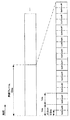
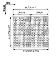
- FIG. 7 is a diagram showing an example of the EPDCCH-PRB-set of this embodiment.
- the horizontal axis is the frequency axis
- the vertical axis is the time axis.
- the base station device 3 sets two EPDCCH-PRB-sets in the mobile station device 1.
- EPDCCH-PRB-set is a set of physical resource blocks including candidate resources for which the mobile station apparatus 1 monitors EPDCCH.
- the base station apparatus 3 transmits information indicating a plurality of physical resource blocks constituting the EPDCCH-PRB-set to the mobile station apparatus 1.
- the base station apparatus 3 can individually set an OFDM symbol for starting the placement of the EPDCCH for each of the EPDCCH-PRB-sets.
- the OFDM symbol for starting the placement of EPDCCH for EPDCCH-PRB-set 1 is 2
- the OFDM symbol for starting the placement of EPDCCH for EPDCCH-PRB-set 2 is 1.
- the virtual cell identity for the EPDCCH may be set individually for each EPDCCH-PRB-set.
- the virtual cell identity for the EPDCCH is a parameter used to generate a pseudo-random sequence that is used to scramble the EPDCCH.
- the virtual cell identity is also referred to as scrambling identity or DMRS scrambling sequence initialization parameter.
- the EPDCCH symbol is scrambled by a pseudo-random sequence.
- the pseudo-random sequence is generated based on the virtual cell identity for the EPDCCH. If the virtual cell identity for the EPDCCH is not set, the pseudo-random sequence is generated based on the physical layer cell identity of the serving cell.
- the value of the physical layer cell identity may be set in the virtual cell identity.
- the DMRS corresponding to the EPDCCH is generated based on the virtual cell identity set for the EPDCCH-PRB-set related to the DMRS.
- EPDCCH candidate The resource candidate that the mobile station apparatus 1 monitors the EPDCCH is referred to as an EPDCCH candidate (candidate). Monitoring means attempting to decode EPDCCH.
- EPDCCH-PRB-set is also referred to as EPDCCH set.
- the base station device 3 maps the EPDCCH to a single PDCCH candidate. In the frequency domain, one EPDCCH-PRB-set may overlap with another EPDCCH-PRB-set.
- EPDCCH and EPDCCH candidates are composed of one or a plurality of ECCE (Enhanced Control Channel Element).
- the ECCE is composed of four EREGs (Enhanced Resource Resource Element Group).
- EREG is composed of nine resource elements.
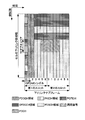
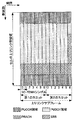
- FIG. 8 is a diagram illustrating an example of the configuration of the EREG in the present embodiment.
- the horizontal axis is the time axis
- the vertical axis is the frequency axis.
- FIG. 8 shows two physical resource blocks that are continuous in the time domain within a subframe. Two physical resource blocks that are continuous in the time domain within a subframe are referred to as a physical resource block pair.
- the physical resource block pair includes 16 EREGs.
- the physical resource block pair includes four ECCEs.
- EREG is configured by resource elements other than resource elements in which DMRS related to EPDCCH is arranged.
- a square with a number i indicates a resource element that constitutes EREG i.
- the EPDCCH symbol is arranged avoiding the resource elements in which the CRS / ZP CSI-RS corresponding to the EPDCCH-PRB-set and the NZP CSI-RS set for the serving cell are arranged.
- the CRS / ZP CSI-RS supported by the EPDCCH-PRB-set may be individually set for each of the EPDCCH-PRB-sets.
- the CRS / ZP CSI-RS corresponding to the EPDCCH-PRB-set may be a CRS / ZP CSI-RS for the serving cell.
- the resource element that transmits the CRS for the serving cell is determined based on the physical layer cell identity of the serving cell.
- Information indicating the number of antenna ports used for CRS transmission to the serving cell is mapped to BCH and transmitted on PBCH.
- the resource element that transmits the CRS corresponding to the EPDCCH-PRB-set uses information indicating the number of antenna ports used for transmitting the CRS corresponding to the EPDCCH-PRB-set, and is used for transmitting the CRS corresponding to the EPDCCH-PRB-set. Given by the frequency shift indicating the resource element number to be assigned and the information indicating the MBSFN subframe for the EPDCCH-PRB-set.
- the mobile station apparatus 1 assumes that the CRS is arranged only in the first OFDM symbol and the second OFDM symbol in the subframe indicated by the information indicating the MBSFN subframe for the EPDCCH-PRB-set.
- EPDCCH symbols are mapped to resource elements. That is, the information indicating the MBSFN subframe for EPDCCH-PRB-set is information used for mapping the EPDCCH to the resource element.
- the MBSFN subframe in the serving cell is indicated by information indicating the MBSFN subframe for the serving cell.
- the base station apparatus 3 provides information indicating the MBSFN subframe for the serving cell, information indicating the MBSFN subframe for EPDCCH-PRB-set 1, and information indicating the MBSFN subframe for EPDCCH-PRB-set 2. Transmit to mobile station apparatus 1.
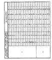
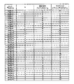
- FIG. 9 is a table showing the EREG corresponding to the ECCE in the EPDCCH-PRB-set.
- EPDCCH-PRB-set-1 is composed of ⁇ 0, 1, 2, 3 ⁇ physical resource block pairs
- EPDCCH-PRB-set-2 is composed of ⁇ 2, 3 ⁇ physical resource block pairs.
- EPDCCH-PRB-set 1 includes 16 ECCEs
- EPDCCH-PRB-set 2 includes 8 ECCEs.
- Each ECCE is numbered individually for each EPDCCH-PRB-set.
- Each EREG is individually numbered for each physical resource block pair.
- a single ECCE is composed of four EREGs within a single PRB.
- ECCE 0 of EPDCCH-PRB-set IV 1 is composed of EREGs 0, 4, 8, and 12 in PRB 0.
- ECCE 0 of EPDCCH-PRB-set IV 2 is composed of EREGs 0, 4, 8, and 12 in PRB 2.
- EPDCCH / EPDCCH candidates correspond to one ECCE, two consecutive ECCEs, four consecutive ECCEs, or eight consecutive ECCEs.
- the number of ECCEs to which a single EPDCCH / EPDCCH candidate corresponds is referred to as an aggregation level.
- the mobile station device 1 does not monitor all ECCE / EPDCCH candidates in the EPDCCH-PRB-set.
- a set of EPDCCH candidates monitored by the mobile station apparatus 1 in the EPDCCH-PRB-set is referred to as EPDCCH USS (UE-specific Search Space).
- EPDCCH USS is defined for each serving cell.
- the EPDCCH USS for the primary cell and the EPDCCH USS for the secondary cell are individually defined.
- the mobile station device 1 monitors at least a DCI format used for scheduling of PDSCH of a certain serving cell in EPDCCH USS for a certain serving cell.
- the mobile station apparatus 1 may monitor the DCI format used for scheduling of PUSCH of a certain serving cell in EPDCCH USS for a certain serving cell.
- the mobile station apparatus 1 may monitor the DCI format used for scheduling of PDSCH of a certain serving cell in a cell different from the certain serving cell.
- the EPDCCH USS for the certain serving cell is defined in a cell different from the certain serving cell. That is, a plurality of EPDCCH USSs for a plurality of serving cells may be configured in a single serving cell.
- a carrier indicator may be included in the DCI format transmitted by a single serving cell in which a plurality of EPDCCH USSs for a plurality of serving cells are configured.
- the carrier indicator is information indicating a serving cell corresponding to the DCI format.
- the EPDCCH USS for a serving cell is defined for each EPDCCH-PRB-set.
- the EPDCCH USS for a serving cell is defined for each aggregation level.
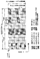
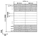
- FIG. 10 is a table showing an example of EPDCCH USS in the present embodiment.
- FIG. 10 shows an example in which an EPDCCH USS for the primary cell and an EPDCCH USS for a single secondary cell are configured in the primary cell.
- the configuration of EPDCCH-PRB-set and ECCE shown in FIG. 9 is assumed.
- the column of the number of EPDCCH candidates indicates the number of EPDCCH candidates constituting the EPDCCH USS.
- the EPDCCH USS corresponding to the primary cell at aggregation level 1 in EPDCCH-PRB-set IV 1 is composed of four EPDCCH candidates.
- the four EPDCCH candidates are an EPDCCH candidate composed of ECCE0, an EPDCCH candidate composed of ECCE1, an EPDCCH candidate composed of ECCE2, and an EPDCCH candidate composed of ECCE3.
- the EPDCCH USS corresponding to the primary cell at aggregation level 2 in EPDCCH-PRB-set IV 1 is composed of four EPDCCH candidates.
- the four EPDCCH candidates are an EPDCCH candidate composed of ECCE6 and ECCE7, an EPDCCH candidate composed of ECCE8 and ECCE9, an EPDCCH candidate composed of ECCE10 and ECCE11, and an EPDCCH candidate composed of ECCE12 and ECCE13.
- the number of EPDCCH candidates constituting the USS for each EPDCCH-PRB-set may be determined based on the number of physical resource block pairs constituting the EPDCCH-PRB-set.
- the number of the ECCE constituting the USS may be determined based on the C-RNTI and the slot number in the radio frame.
- FIG. 11 is a diagram illustrating an example of the arrangement of physical channels and physical signals in the uplink subframe according to the present embodiment.
- the mobile station apparatus 1 can transmit an uplink physical channel (PUCCH, PUSCH, PRACH) and an uplink physical signal (DMRS, SRS) in the uplink subframe.
- PUCCH uplink physical channel
- PUSCH PUSCH
- PRACH uplink physical channel
- DMRS uplink physical signal
- a plurality of PUCCHs transmitted by a plurality of mobile station apparatuses 1 are frequency, time, and code-multiplexed.
- a single mobile station apparatus 1 can transmit one PUCCH in a single uplink subframe.
- a plurality of PUSCHs are frequency and space multiplexed.
- a single mobile station apparatus 1 can transmit a single PUSCH in a single uplink subframe of a single cell.
- PUCCH and PUSCH are frequency multiplexed.
- a single mobile station apparatus 1 can simultaneously transmit a single PUSCH and a single PUCCH in a single uplink subframe of a single cell.
- the PRACH is arranged over a single subframe or two subframes.
- a plurality of PRACHs transmitted from a plurality of mobile station apparatuses 1 are code-multiplexed.
- a single mobile station apparatus 1 does not transmit PRACH and other uplink signals simultaneously in a single cell.
- SRS is transmitted using the last SC-FDMA symbol in the uplink subframe.
- the mobile station apparatus 1 does not simultaneously transmit SRS and PUCCH / PUSCH / PRACH in a single SC-FDMA symbol of a single cell.
- the mobile station apparatus 1 transmits PUSCH and / or PUCCH using an SC-FDMA symbol excluding the last SC-FDMA symbol in the uplink subframe.
- the SRS can be transmitted using the last SC-FDMA symbol in the uplink subframe. That is, in a single uplink subframe of a single cell, the mobile station device 1 can simultaneously transmit SRS and PUSCH / PUCCH.
- DMRS is time-multiplexed with PUCCH or PUSCH. For simplicity of explanation, DMRS is not shown in FIG.
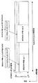
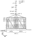
- FIG. 12 is a diagram illustrating a physical resource block in which the PUCCH according to the present embodiment is arranged.
- the horizontal axis is a time axis
- the vertical axis is a frequency axis.
- n PRB is the number of physical resource blocks in the frequency domain
- N UL PRB is the number of physical resource blocks included in the uplink bandwidth
- m is the physical resource block in which the PUCCH is arranged. It is a number for identification.
- a single PUCCH is arranged in two physical resource blocks. That is, a single PUCCH is arranged in one physical resource block in the first slot and one physical resource block in the second slot. Also, one physical resource block in the first slot is symmetric with one physical resource block in the second slot with respect to the center frequency of the uplink band.
- a plurality of PUCCHs are code-multiplexed in the two physical resource blocks.
- a cyclic shift ⁇ and an orthogonal code w (i) are used. That is, the PUCCH resource is specified by a combination of the number m, the cyclic shift ⁇ , and the orthogonal sequence w (i).
- n (p) CS is a cyclic shift index.
- w (i) corresponds to one of [+1 +1 +1 +1], [+1 ⁇ 1 +1 ⁇ 1], and [+1 ⁇ 1 ⁇ 1 +1].
- FIG. 13 is a diagram illustrating a correspondence between the PUCCH resource index and the PUCCH resource according to the present embodiment.
- m is a number for identifying the physical resource block to which the PUCCH resource corresponds
- n (1, p) PUCCH is the index of the PUCCH resource for antenna port p
- n (p) OC is the antenna port.
- An orthogonal sequence index for p, and n (p) CS is a cyclic shift index for antenna port p.
- the index of the PUCCH resource is 1
- m is
- the orthogonal sequence index n (p) OC is 0, and the cyclic shift index n (p) OC is 1.
- FIG. 14 is a diagram illustrating a method for generating a PUCCH according to the present embodiment.
- N PUCCH SF is a spreading factor of the orthogonal sequence w (i) in a single slot and is 4.
- N PUCCH seq is the number of subcarriers included in the bandwidth of a single PUCCH, and is 12.
- p is an antenna port number, and P is the number of antenna ports used for PUCCH transmission.
- the mobile station apparatus 1 determines the sequence r ′ u, v (n).
- u is a sequence group number.
- the mobile station apparatus 1 determines the value of u based at least on the virtual cell identity.
- the mobile station device 1 determines the u value based on at least the physical layer cell identity.
- v is a sequence number and is always 0 for PUCCH. The virtual cell identity for PUCCH and the virtual cell identity for EPDCCH are set individually.
- the base station device 3 determines the value of the virtual cell identity for the PUCCH for each of the mobile station devices 1, and transmits information indicating the determined value of the virtual cell identity to each of the mobile station devices 1. Also good. Note that the base station device 3 does not have to transmit information indicating the value of the virtual cell identity for the PUCCH to the mobile station device 1.
- the mobile station apparatus 1 sets the virtual cell identity value for the PUCCH based on the information (signaling) indicating the virtual cell identity value for the PUCCH.
- the sequence group number u may hop for each slot based on a pseudo-random sequence.
- the base station apparatus 3 transmits information indicating whether hopping of the sequence group number u is valid. Further, the mobile station apparatus 1 determines whether or not to hop the sequence group number u based on information indicating whether hopping of the sequence group number u is valid.
- the mobile station apparatus 1 and the base station apparatus 3 store a sequence r ′ u, v (n) having a sequence length of 12 defined for each of the sequence group numbers, and correspond to the determined u.
- the sequence r ′ u, v (n) is read (generated).
- the mobile station apparatus 1 multiplies the sequence r ′ u, v (n) by e j ⁇ pn , thereby obtaining the sequence r ( ⁇ p) u, v (n).
- ⁇ p is the amount of phase rotation for each subcarrier.
- the phase rotation of the sequence r ′ u, v (n) in the frequency domain corresponds to a cyclic shift of the PUCCH SC-FDMA symbol in the time domain. Therefore, in this embodiment, ⁇ p is also simply referred to as a cyclic shift.
- the mobile station apparatus 1 generates a modulation symbol block y (p) (n) by multiplying the sequence r ( ⁇ p) u, v (n) by 1 / ⁇ P and d (0).
- d (0) is a modulation symbol generated by subjecting 1-bit or 2-bit HARQ-ACK to BPSK (Binary Phase Shift Keying) modulation or QPSK (Quadrature Phase Shift Keying) modulation.
- Mobile station apparatus 1 multiplies the S (n s) in the block y of the modulation symbols (p) (n), and, perpendicular to S (n s) block of modulation symbols multiplied by the y (p) (n)
- a block z (p) (*) of modulation symbols is generated by spreading with the sequence w n (p) OC (m).
- S (n s), based on the number of PUCCH resources, 1 or e j ⁇ / 2 is selected.
- the mobile station apparatus 1 maps the modulation symbol block z (p) (*) to the two physical resource blocks m to which the PUCCH corresponds.
- the mobile station apparatus 1 arranges the modulation symbol block z (p) (*) in the SC-FDMA symbols of ⁇ 0, 1, 5, 6 ⁇ of the first slot in the subframe, and then Arranged in ⁇ 0, 1, 5, 6 ⁇ SC-FDMA symbols of 2 slots.
- z (p) (*) is arranged in order from the subcarrier with the smallest number.
- FIG. 15 is a diagram illustrating a method of generating a DMRS sequence for the PUCCH according to the present embodiment.
- N PUCCH RS is the number of SC-FDMA symbols used for transmission of DMRS for PUCCH per single slot, and is 3.
- M RS SC is the length of the reference signal sequence and is 12.
- the mobile station apparatus 1 generates a sequence r ( ⁇ p) u, v (n) in the same manner as the PUCCH. That is, when the mobile station apparatus 1 has not received the virtual cell identity for the PUCCH, the mobile station apparatus 1 generates the sequence r ( ⁇ p) u, v (n) based on at least the physical layer cell identity, and the virtual station identity for the PUCCH When the cell identity is received, the sequence r ( ⁇ p) u, v (n) is generated based on at least the virtual cell identity.
- the mobile station apparatus 1 multiplies the sequence r ( ⁇ p) u, v (n) by 1 / ⁇ P, w ′ (p) (m), and z (m), thereby obtaining the sequence r (p ) Generate PUCCH (*).
- w ′ (p) (m) is an orthogonal sequence for DMRS of PUCCH.
- z (m) is always 1 for DMRS of PUCCH used for transmission of HARQ-ACK only. That is, when generating a PUCCH DMRS used for transmission of only HARQ-ACK, it is not necessary to perform a process of multiplying z (m).
- mobile station apparatus 1 arranges sequence r (p) PUCCH (*) in ⁇ 2, 3, 4 ⁇ SC-FDMA symbols of the first slot, and then in the second slot. Place ⁇ 2, 3, 4 ⁇ .
- r (p) PUCCH (*) is arranged in order from the subcarrier with the smallest number.
- w ′ (i) is [1 1 1], [1 e j2 ⁇ / 3 e j4 ⁇ / 3 ] and [1 e j4 ⁇ / 3 e j2 ⁇ . / 3 ].
- the mobile station apparatus 1 determines a PUCCH resource used for transmission of HARQ-ACK for a transport block received by PDSCH based on at least n ECCE, q and N (e1) PUCCH, q and ⁇ ARO To do.
- n ECCE is the number of the first ECCE used for transmission of the DCI format used for PDSCH scheduling. That is, n ECCE is the lowest ECCE index that constitutes an EPDCCH / EPDCCH candidate used for transmission of the DCI format used for PDSCH scheduling. For example, when ECCE2 and ECCE3 are used for transmission of the DCI format used for PDSCH scheduling, n ECCE is 2.
- N (e1) PUCCH, q is an upper layer parameter / offset value set for EPDCCH-PRB-set q.
- the mobile station apparatus 1 detects the DCI format in the EPDCCH-PRB-set q, the mobile station apparatus 1 uses the parameter / offset value N (e1) PUCCH, q corresponding to the EPDCCH-PRB-set q to allocate the PUCCH resource. decide.
- ⁇ ARO is a parameter / offset value determined based on information included in the DCI format used for PDSCH scheduling.
- a PUCCH resource may be determined.
- the EPDCCH candidate for EPDCCH-PRB-set 1 and the EPDCCH candidate for EPDCCH-PRB-set 2 correspond to the same EREG, and the EPDCCH candidate for EPDCCH-PRB-set 1 and the EPDCCH candidate for EPDCCH-PRB-set 2
- the mobile station apparatus 1 cannot determine whether the DCI format is transmitted by the EPDCCH-PRB-set 1 or the EPDCCH-PRB-set 2.
- apparatus 1 can not determine whether to use either for EPDCCH-PRB-set 1 to the determination of the PUCCH resource parameter N (e1) PUCCH, 1 and for EPDCCH-PRB-set 2 parameter N (e1) PUCCH, 2 of That There is a problem.
- the mobile station apparatus 1 includes an EPDCCH candidate composed of ECCE12 and ECCE13 in EPDCH-PRB-set 1, and an EPDCCH candidate composed of ECCE4 and ECCE5 in EPDCH-PRB-set 2. Monitor.
- both of the EPDCCH candidate composed of ECCE12 and ECCE13 in EPDCH-PRB-set 1 and the EPDCCH candidate composed of ECCE4 and ECCE5 in EPDCH-PRB-set 2 are physical resource block pairs. 3 EREG0, 1, 4, 5, 8, 9, 12, and 13. Therefore, when the mobile station apparatus 1 detects the DCI format in EREG0, 1, 4, 5, 8, 9, 12, and 13, the detected DCI formats are EPDCH-PRB-set 1 and EPDCH-PRB. -Cannot determine which of set 2 is supported.
- the mobile station apparatus 1 of the first embodiment is set to monitor the same DCI format for the same serving cell in the EPDCCH USS for the EPDCCH-PRB-set IV 1 and the EPDCCH USS for the EPDCCH-PRB-set IV 2 in a certain serving cell. Whether or not it is considered that the DCI format is transmitted only by the EPDCCH arranged in the EPDCCH-PRB-set 1 is determined based on at least whether or not the DCI format is transmitted.
- the mobile station apparatus 1 of the first embodiment is configured to monitor the same DCI format for the same serving cell in both the EPDCCH-PRB-set-1 EPDCCH candidate and the EPDCCH-PRB-set 2 EPDCCH candidate. Based on at least, it is determined whether or not it is considered that the DCI format is transmitted only by the EPDCCH arranged in the EPDCCH-PRB-set 1.
- the mobile station apparatus 1 includes: a setting unit that sets EPDCCH-PRB-set 1 and EPDCCH-PRB-set 2; and a subframe of a certain serving cell, EPDCCH candidate and EPDCCH-PRB-set IV2's EPDCCH candidate monitoring unit for DCI format, parameters / offset values corresponding to EPDCCH-PRB-setV1, or parameters / corresponding to EPDCCH-PRB-set IV2
- a selector that selects an offset and selects a PUCCH resource based on the selected parameter / offset value; and a transmitter that transmits HARQ-ACK using the selected PUCCH resource.
- the EREG corresponding to the EPDCCH candidate of EPDCCH-PRB-set 1 and the EREG corresponding to the EPDCCH candidate of EPDCCH-PRB-set 2 are the same, and the EPDCCH candidate of EPDCCH-PRB-set 1 and the EPDCCH-PRB-set 1
- the mobile station apparatus 1 uses only the EPDCCH arranged in the EPDCCH-PRB-set 1
- the PUCCH resource is determined using the parameter N (e1) PUCCH, 1 for the EPDCCH-PRB-set 1.
- the base station apparatus 3 tries to receive HARQ-ACK using the PUCCH resource determined using the parameter N (e1) PUCCH, 1 for EPDCCH-PRB-set 1.
- the EREG corresponding to the EPDCCH candidate of EPDCCH-PRB-set 1 and the EREG corresponding to the EPDCCH candidate of EPDCCH-PRB-set 2 are the same, and the EPDCCH candidate of EPDCCH-PRB-set 1 and the EPDCCH-PRB-set
- the mobile station apparatus 1 uses the DCI format based on the carrier indicator included in the DCI format. To which serving cell and which EPDCCH-PRB-set the DCI format corresponds to.
- the mobile station apparatus 1 can determine whether the detected DCI format corresponds to EPDCH-PRB-set 1 or EPDCH-PRB-set ⁇ 2.
- HARQ-ACK for the transmitted transport block can be efficiently transmitted using PUCCH.
- the mobile station apparatus 1 of the second embodiment determines that the value of the virtual cell identity for EPDCCH-PRB-set-1 is at least based on whether the value of the virtual cell identity for EPDCCH-PRB-set 2 is the same as the value of EPDCCH-PRB- It is determined whether or not it is considered that the DCI format is transmitted only by the EPDCCH arranged in the set 1.
- the mobile station apparatus 1 of the second embodiment assigns virtual cell identities for EPDCCH-PRB-set 1, EPDCCH-PRB-set 2, EPDCCH-PRB-set 1 and virtual cell identities for EPDCCH-PRB-set 2.
- a setting unit to set a receiving unit that monitors a DCI format with EPDCCH-candidate of EPDCCH-PRB-set-1 and EPDCCH-candidate of EPDCCH-PRB-set 2, and EPDCCH-PRB-set 1
- the parameter / offset value corresponding to EPDCCH-PRB-set 2 is selected, and the selected parameter / offset value is selected.
- the EREG corresponding to the EPDCCH candidate of EPDCCH-PRB-set 1 and the EREG corresponding to the EPDCCH candidate of EPDCCH-PRB-set 2 are the same, and the EPDCCH candidate of EPDCCH-PRB-set 1 and the EPDCCH-PRB-set 1 Mobile station apparatus 1 is configured to monitor the same DCI format for the same serving cell in both of the two EPDCCH candidates, and the virtual cell identity value for EPDCCH-PRB-set 1 is the virtual cell for EPDCCH-PRB-set 2 When the identity value is the same, the mobile station apparatus 1 considers that the DCI format is transmitted only by the EPDCCH arranged in the EPDCCH-PRB-set 1, and the DCI format is transmitted in the EREG.
- the PUCCH resource is determined using the parameter N (e1) PUCCH, 1 for EPDCCH-PRB-set 1.
- the base station apparatus 3 tries to receive HARQ-ACK using the PUCCH resource determined using the parameter N (e1) PUCCH, 1 for EPDCCH-PRB-set 1.
- the mobile station apparatus 1 can determine whether the EPDCCH corresponds to EPDCCH-PRB-set 1 or EPDCCH-PRB-set 2 .
- the mobile station apparatus 1 can determine whether the detected DCI format corresponds to EPDCH-PRB-set 1 or EPDCH-PRB-set ⁇ 2.
- HARQ-ACK for the transmitted transport block can be efficiently transmitted using PUCCH.
- the mobile station apparatus 1 of the third embodiment determines whether the EPDCCH candidate of EPDCCH-PRB-set 1 corresponds to the resource element corresponding to the EPDCCH candidate of EPDCCH-PRB-set 2 based on whether the resource element corresponding to the EPDCCH-PRB-set 2 -It is determined whether or not it is considered that the DCI format is transmitted only by the EPDCCH arranged in the PRB-set 1.
- the EREG corresponding to the EPDCCH-PRB-set 1 EPDCCH candidate corresponds to the EREG corresponding to the EPDCCH-PRB-set 2 EPDCCH candidate, and the CRS and ZP CSI corresponding to the EPDCCH-PRB-set 1 included in the EREG -
- the OFDM symbol that starts the placement of RS and EPDCCH is the same as the OFDM symbol that starts the placement of CRS, ZP CSI-RS, and EPDCCH corresponding to EPDCCH-PRB-set 2 included in the EREG
- the resource element corresponding to the EPDCCH-PRB-set 1 EPDCCH candidate is the same as the resource element corresponding to the EPDCCH-PRB-set 2 EPDCCH candidate.
- the mobile station apparatus 1 of the third embodiment when the EREG corresponding to the EPDCCH candidate of EPDCCH-PRB-set 1 and the EREG corresponding to the EPDCCH candidate of EPDCCH-PRB-set 2 are the same,
- the CRS and ZP CSI-RS corresponding to the EPDCCH-PRB-set 1 included in the EDCCH and the OFDM symbol for starting the placement of the EPDCCH are the CRS and ZP CSI-corresponding to the EPDCCH-PRB-set 2 included in the EREG.
- the mobile station apparatus 1 obtains the virtual cell identities for the EPDCCH-PRB-set 1, EPDCCH-PRB-set 2, EPDCCH-PRB-set 1 and the virtual cell identities for the EPDCCH-PRB-set 2.
- a setting unit to set a receiving unit that monitors a DCI format with EPDCCH-candidate of EPDCCH-PRB-set-1 and EPDCCH-candidate of EPDCCH-PRB-set 2, and EPDCCH-PRB-set 1
- the parameter / offset value corresponding to EPDCCH-PRB-set 2 is selected, and the selected parameter / offset value is selected.
- the resource element corresponding to the EPDCCH candidate of EPDCCH-PRB-set 1 and the resource element corresponding to the EPDCCH candidate of EPDCCH-PRB-set 2 are the same, and the EPDCCH candidate of EPDCCH-PRB-set 1 and the EPDCCH-PRB -The mobile station apparatus 1 is configured to monitor the same DCI format for the same serving cell in both of the EPDCCH candidates of -set 2, and the value of the virtual cell identity for EPDCCH-PRB-set 1 is the same for EPDCCH-PRB-set 2 When the value is the same as the value of the virtual cell identity, the mobile station apparatus 1 considers that the DCI format is transmitted only by the EPDCCH arranged in the EPDCCH-PRB-set 1, and the EREG When the DCI format is detected in step 1 , the PUCCH resource is determined using the parameter N (e1) PUCCH, 1 for EPDCCH-PRB-set 1. In this case, the base station apparatus 3 tries to receive HARQ-ACK using the PUC
- the mobile station apparatus 1 can determine whether the detected DCI format corresponds to EPDCH-PRB-set 1 or EPDCH-PRB-set ⁇ 2.
- HARQ-ACK for the transmitted transport block can be efficiently transmitted using PUCCH.
- the resource element to which the EPDCCH candidate of EPDCCH-PRB-set 1 corresponds and the resource element to which the EPDCCH candidate of EPDCCH-PRB-set 2 correspond are the same, and the EPDCCH-PRB-
- the mobile station apparatus 1 is configured to monitor the same DCI format for the same serving cell in both the EPDCCH candidate of the set 1 and the EPDCCH-PRB-set 2 of the EPDCCH-PRB-set 2, and the virtual cell identity for the EPDCCH-PRB-set 1 of if the value is equal to the value of the virtual cell identity for EPDCCH-PRB-set 2 is, EPDCCH-PRB-set parameter N (e1) for 1 PUCCH, 1 and PUCCH resources that are determined using the EPD CH-PRB-set 2 Parameter N (e1) with respect to PUCCH, attempts to receive the HARQ-ACK 2 in both PUCCH resource is determined using.
- the base station apparatus 3 in the fourth embodiment the parameter N (e1 for PDCCH-PRB-set parameter N (e1) for 1 PUCCH, 1 PUCCH resources and EPDCCH-PRB-set 2 is determined using the )
- the power in the PUCCH resource determined using PUCCH, 2 is measured, and based on the measured power, it is determined which PUCCH resource has transmitted the HARQ-ACK.
- the base station apparatus 3 transmits the HARQ-ACK for the transport block transmitted on the PDSCH to the PUCCH. Can be received.
- the EREG corresponding to the EPDCCH candidate of EPDCCH USS and the EREG corresponding to the EPDCCH candidate of EPDCCH CSS are the same as at least one of the first to third embodiments of the present invention. Applies in some cases. That is, the first to fourth embodiments of the present invention can be applied when the EREG corresponding to the EPDCCH candidate of the EPDCCH USS and the EREG corresponding to the EPDCCH candidate of the EPDCCH CSS are the same.
- EPDCCH CSS is a set of EPDCCH candidates monitored by a plurality of mobile station apparatuses 1.
- EPDCCH CSS may be defined in EPDCCH-PRB-set IV1 or EPDCCH-PRB-set IV2.
- EPDCCH CSS may be defined in EPDCCH-PRB-set that is set separately from EPDCCH-PRB-set IV 1 and EPDCCH-PRB-set IV 2.
- the base station apparatus 3 may broadcast information related to the setting of the EPDCCH CSS.
- the virtual cell identity of EPDCCH-PRB-set IV 1 and the virtual cell identity of EPDCCH-PRB-set IV 2 may be set individually.
- the pseudo random sequence used for scrambling the EPDCCH corresponding to the EPDCCH CSS may be generated based on the physical layer cell identity.
- the DCI format transmitted by EPDCCH USS includes a carrier indicator
- the DCI format transmitted by EPDCCH CSS does not include a carrier indicator.
- the DCI format transmitted by EPDCCH CSS corresponds to the serving cell in which the DCI format is transmitted.
- the set of information fields defined in EPDCCH CSS DCI format 1A and the set of information fields defined in EPDCCH USS DCI format 1A may be different.
- the number of bits of a DCI format that does not include a carrier indicator may be the same as the number of bits of another DCI format that includes a carrier indicator.
- the carrier indicator may not be included, and the number of bits of DCI format 1A for the primary cell may be the same as the number of bits of DCI format 1A including the carrier indicator and for the secondary cell.
- the mobile station apparatus 1 may determine the PUCCH resource based on the parameter N (e1) PUCCH, 1 for the EPDCCH CSS.
- the EPDCCH CSS is defined in the EPDCCH-PRB-set 1 and the DCI format is detected in the EPDCCH CSS
- the resource of the PUCCH is assigned based on the parameter N (e1) PUCCH, 1 for the EPDCCH-PRB-set 1 You may decide.
- the EREG / resource element to which the EPDCCH candidate of EPDCCH CSS corresponds and the EREG / resource element to which the EPDCCH candidate of EPDCCH USS correspond are the same, and the same bit in both the EPDCCH candidate of EPDCCH CSS and the EPDCCH candidate of EPDCCH USS.
- the mobile station apparatus 1 is set to monitor a number of DCI formats, and the set of information fields included in the DCI format corresponding to EPDCCH CSS is different from the set of information fields included in the DCI format corresponding to EPDCCH USS.
- the virtual cell identity value for EDC is the same as the virtual cell identity / physical layer cell identity value for EPDCCH CSS.
- the mobile station apparatus 1 may be regarded as DCI format is transmitted only in EPDCCH disposed EPDCCH CSS.
- the mobile station apparatus 1 can determine whether the detected DCI format corresponds to EPDCCH CSS or EPDCCH USS, and the mobile station apparatus 1 can perform HARQ for the transport block transmitted by PDSCH.
- -ACK can be efficiently transmitted using PUCCH.
- FIG. 16 is a schematic block diagram showing the configuration of the mobile station apparatus 1 of the present embodiment.
- the mobile station apparatus 1 includes an upper layer processing unit 101, a control unit 103, a receiving unit 105, a transmitting unit 107, and a transmission / reception antenna 109.
- the higher layer processing unit 101 includes a radio resource control unit 1011, a PUCCH resource determination unit 1013, and a setting unit 1015.
- the reception unit 105 includes a decoding unit 1051, a demodulation unit 1053, a demultiplexing unit 1055, a radio reception unit 1057, a channel measurement unit 1059, and a detection unit 1061.
- the transmission unit 107 includes an encoding unit 1071, a modulation unit 1073, a multiplexing unit 1075, a radio transmission unit 1077, and an uplink reference signal generation unit 1079.
- the upper layer processing unit 101 outputs uplink data (transport block) generated by a user operation or the like to the transmission unit 107.
- the upper layer processing unit 101 includes a medium access control (MAC: Medium Access Control) layer, a packet data integration protocol (Packet Data Convergence Protocol: PDCP) layer, a radio link control (Radio Link Control: RLC) layer, and radio resource control. Process the (Radio Resource Control: RRC) layer. Also, the radio resource control unit 1011 generates information arranged in each uplink channel and outputs the information to the transmission unit 107.
- MAC Medium Access Control
- PDCP Packet Data Convergence Protocol
- RLC Radio Link Control
- RRC Radio Resource Control
- the radio resource control unit 1011 generates information arranged in each uplink channel and outputs the information to the transmission unit 107.
- the PUCCH resource determination unit 1015 included in the higher layer processing unit 101 determines a PUCCH resource used for transmitting uplink control information.
- the setting unit 1015 included in the upper layer processing unit 101 manages various setting information of the own device. For example, the setting unit 1015 performs various settings according to the signaling received from the base station device 3.
- the control unit 103 generates a control signal for controlling the receiving unit 105 and the transmitting unit 107 based on the control information from the higher layer processing unit 101. Control unit 103 outputs the generated control signal to receiving unit 105 and transmitting unit 107 to control receiving unit 105 and transmitting unit 107.
- the receiving unit 105 separates, demodulates, and decodes the received signal received from the base station apparatus 3 via the transmission / reception antenna 109 according to the control signal input from the control unit 103, and sends the decoded information to the upper layer processing unit 101. Output.
- the radio reception unit 1057 converts the downlink signal received via the transmission / reception antenna 109 into an intermediate frequency (down-conversion: down covert), removes unnecessary frequency components, and maintains the signal level appropriately. Then, the amplification level is controlled, quadrature demodulation is performed based on the in-phase component and the quadrature component of the received signal, and the quadrature demodulated analog signal is converted into a digital signal.
- the radio reception unit 1057 removes a portion corresponding to a guard interval (Guard Interval: GI) from the converted digital signal, performs a fast Fourier transform (FFT Fourier Transform: ⁇ ⁇ ⁇ ⁇ FFT) on the signal from which the guard interval has been removed, and outputs a frequency. Extract the region signal.
- GI Guard Interval
- the demultiplexing unit 1055 separates the extracted signals into PHICH, PDCCH, EPDCCH, PDSCH, and downlink reference signals. Further, demultiplexing section 1055 compensates the propagation path of PHICH, PDCCH, EPDCCH, and PDSCH from the estimated propagation path value input from channel measurement section 1059. Also, the demultiplexing unit 1055 outputs the demultiplexed downlink reference signal to the channel measurement unit 1059.
- the demodulating unit 1053 multiplies the PHICH by a corresponding code and synthesizes the signal, demodulates the synthesized signal using a BPSK (Binary Phase Shift Shift Keying) modulation method, and outputs the demodulated signal to the decoding unit 1051.
- Decoding section 1051 decodes the PHICH addressed to the own apparatus, and outputs the decoded HARQ indicator to higher layer processing section 101.
- the demodulation unit 1053 demodulates the modulation scheme notified by the downlink grant such as QPSK (Quadrature Shift Keying), 16QAM (Quadrature Amplitude Modulation), 64QAM, and the like to the decoding unit 1051.
- Decoding section 1051 performs decoding based on the information regarding the coding rate notified by the downlink control information, and outputs the decoded downlink data (transport block) to higher layer processing section 101.
- the channel measurement unit 1059 measures the downlink path loss and channel state from the downlink reference signal input from the demultiplexing unit 1055, and outputs the measured path loss and channel state to the upper layer processing unit 101. Also, channel measurement section 1059 calculates an estimated value of the downlink propagation path from the downlink reference signal, and outputs it to demultiplexing section 1055.
- the detection unit 1061 detects downlink control information using the PDCCH and / or EPDCCH, and outputs the detected downlink control information to the upper layer processing unit 101.
- the detection unit 1061 performs demodulation and decoding of the QPSK modulation scheme on the PDCCH and / or EPDCCH.
- the detection unit 1061 attempts blind decoding of PDCCH and / or EPDCCH, and when the blind decoding is successful, outputs the downlink control information to the higher layer processing unit 101.
- the transmission unit 107 generates an uplink reference signal according to the control signal input from the control unit 103, encodes and modulates the uplink data (transport block) input from the higher layer processing unit 101, PUCCH, The PUSCH and the generated uplink reference signal are multiplexed and transmitted to the base station apparatus 3 via the transmission / reception antenna 109.
- the encoding unit 1071 performs encoding such as convolutional encoding and block encoding on the uplink control information input from the higher layer processing unit 101.
- the encoding unit 1071 performs turbo encoding based on information used for PUSCH scheduling.
- the modulation unit 1073 modulates the coded bits input from the coding unit 1071 using a modulation method notified by downlink control information such as BPSK, QPSK, 16QAM, 64QAM, or a modulation method predetermined for each channel. .
- Modulation section 1073 determines the number of spatially multiplexed data sequences based on information used for PUSCH scheduling, and uses MIMO SM (Multiple Input Multiple Output Spatial Multiplexing) to transmit a plurality of data transmitted on the same PUSCH. Are mapped to a plurality of sequences, and precoding is performed on the sequences.
- Modulation section 1073 spreads PUCCH using cyclic shift and / or orthogonal sequences.
- the uplink reference signal generation unit 1079 generates a reference signal sequence based on a physical layer cell identity (physical layer cell identity: PCI) for identifying the base station apparatus 3 or a virtual cell identity.
- PCI physical layer cell identity
- the multiplexing unit 1075 rearranges the PUSCH modulation symbols in parallel according to the control signal input from the control unit 103 and then performs a discrete Fourier transform (DFT). Also, multiplexing section 1075 multiplexes the PUCCH and PUSCH signals and the generated uplink reference signal for each transmission antenna port. That is, multiplexing section 1075 arranges the PUCCH and PUSCH signals and the generated uplink reference signal in the resource element for each transmission antenna port.
- DFT discrete Fourier transform
- the radio transmission unit 1077 performs inverse fast Fourier transform (IFFT) on the multiplexed signal, performs SC-FDMA modulation, and adds a guard interval to the SC-FDMA-modulated SC-FDMA symbol.
- IFFT inverse fast Fourier transform
- Generating a baseband digital signal converting the baseband digital signal to an analog signal, generating an in-phase component and a quadrature component of an intermediate frequency from the analog signal, removing an extra frequency component for the intermediate frequency band,
- the intermediate frequency signal is converted to a high frequency signal (up-conversion: up convert), an extra frequency component is removed, the power is amplified, and output to the transmission / reception antenna 109 for transmission.
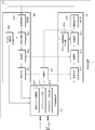
- FIG. 17 is a schematic block diagram showing the configuration of the base station apparatus 3 of the present embodiment.
- the base station apparatus 3 includes an upper layer processing unit 301, a control unit 303, a reception unit 305, a transmission unit 307, and a transmission / reception antenna 309.
- the higher layer processing unit 301 includes a radio resource control unit 3011, a scheduling unit 3013, and a PUCCH resource determination unit 3015.
- the reception unit 305 includes a decoding unit 3051, a demodulation unit 3053, a demultiplexing unit 3055, a wireless reception unit 3057, and a channel measurement unit 3059.
- the transmission unit 307 includes an encoding unit 3071, a modulation unit 3073, a multiplexing unit 3075, a radio transmission unit 3077, and a downlink reference signal generation unit 3079.
- the upper layer processing unit 301 includes a medium access control (MAC: Medium Access Control) layer, a packet data integration protocol (Packet Data Convergence Protocol: PDCP) layer, a radio link control (Radio Link Control: RLC) layer, a radio resource control (Radio). Resource (Control: RRC) layer processing. Further, upper layer processing section 301 generates control information for controlling receiving section 305 and transmitting section 307 and outputs the control information to control section 303.
- MAC Medium Access Control
- PDCP Packet Data Convergence Protocol
- RLC Radio Link Control
- Radio Radio Resource
- the radio resource control unit 3011 included in the higher layer processing unit 301 generates downlink data (transport block), system information block, RRC signal, MAC CE (Control Element), etc. arranged in the downlink PDSCH, or Obtained from the upper node and output to the transmission unit 307. Further, the radio resource control unit 3011 manages various setting information of each mobile station apparatus 1.
- the scheduling unit 3013 included in the higher layer processing unit 301 assigns the physical channel (PDSCH and PUSCH) to the frequency, subframe, and physical channel (PDSCH) based on the channel estimation value and the channel quality input from the channel measurement unit 3059. And the PUSCH) coding rate, modulation scheme, transmission power, and the like. Based on the scheduling result, scheduling section 3013 generates control information for controlling receiving section 305 and transmitting section 307 and outputs the control information to control section 303. In addition, the scheduling unit 3013 outputs the scheduling results of the physical channels (PDSCH and PUSCH) to the control information generation unit 3015.
- the PUCCH resource determination unit 3015 included in the higher layer processing unit 301 determines a PUCCH resource used for reception of uplink control information.
- the control unit 303 generates a control signal for controlling the reception unit 305 and the transmission unit 307 based on the control information from the higher layer processing unit 301.
- the control unit 303 outputs the generated control signal to the reception unit 305 and the transmission unit 307 and controls the reception unit 305 and the transmission unit 307.
- the receiving unit 305 separates, demodulates and decodes the received signal received from the mobile station apparatus 1 via the transmission / reception antenna 309 according to the control signal input from the control unit 303, and outputs the decoded information to the higher layer processing unit 301.
- the radio reception unit 3057 converts an uplink signal received via the transmission / reception antenna 309 into an intermediate frequency (down-conversion: down covert), removes unnecessary frequency components, and appropriately maintains the signal level. In this way, the amplification level is controlled, and based on the in-phase and quadrature components of the received signal, quadrature demodulation is performed, and the quadrature demodulated analog signal is converted into a digital signal.
- the wireless receiver 3057 removes a portion corresponding to a guard interval (Guard Interval: GI) from the converted digital signal.
- the radio reception unit 3057 performs fast Fourier transform (FFT Fourier Transform: ⁇ FFT) on the signal from which the guard interval is removed, extracts a frequency domain signal, and outputs the signal to the demultiplexing unit 3055.
- FFT Fourier Transform ⁇ FFT
- the demultiplexing unit 3055 demultiplexes the signal input from the radio receiving unit 3057 into signals such as PUCCH, PUSCH, and uplink reference signal. This separation is performed based on radio resource allocation information included in the uplink grant that is determined in advance by the radio resource control unit 3011 by the base station device 3 and notified to each mobile station device 1. In addition, demultiplexing section 3055 compensates for the propagation paths of PUCCH and PUSCH from the propagation path estimation value input from channel measurement section 3059. Further, the demultiplexing unit 3055 outputs the separated uplink reference signal to the channel measurement unit 3059.
- the demodulator 3053 performs inverse discrete Fourier transform (Inverse Discrete Fourier Transform: IDFT) on the PUSCH, acquires modulation symbols, and performs BPSK (Binary Shift Keying), QPSK, 16QAM, and PUCCH and PUSCH modulation symbols respectively.
- IDFT inverse discrete Fourier transform
- the received signal is demodulated using a predetermined modulation scheme such as 64QAM, or a modulation scheme that the own device has previously notified to each mobile station device 1 using an uplink grant.
- Demodulation section 3053 is the same by using MIMO SM based on the number of spatially multiplexed sequences notified in advance to each mobile station apparatus 1 using an uplink grant and information indicating precoding performed on these sequences.
- the modulation symbols of a plurality of uplink data transmitted on the PUSCH are separated.
- the decoding unit 3051 encodes the demodulated PUCCH and PUSCH encoded bits in a predetermined encoding method in advance or the mobile station apparatus 1 previously notified to the mobile station apparatus 1 using an uplink grant. Decoding is performed at a rate, and the decoded uplink data and uplink control information are output to the upper layer processing section 101. When PUSCH is retransmitted, decoding section 3051 performs decoding using the encoded bits held in the HARQ buffer input from higher layer processing section 301 and the demodulated encoded bits.
- Channel measurement section 309 measures an estimated channel value, channel quality, and the like from the uplink reference signal input from demultiplexing section 3055 and outputs the result to demultiplexing section 3055 and higher layer processing section 301.
- the transmission unit 307 generates a downlink reference signal according to the control signal input from the control unit 303, encodes and modulates the HARQ indicator, downlink control information, and downlink data input from the higher layer processing unit 301. Then, the PHICH, PDCCH, EPDCCH, PDSCH, and downlink reference signal are multiplexed, and the signal is transmitted to the mobile station apparatus 1 via the transmission / reception antenna 309.
- the encoding unit 3071 is a predetermined encoding method such as block encoding, convolutional encoding, turbo encoding, and the like for the HARQ indicator, downlink control information, and downlink data input from the higher layer processing unit 301 Or is encoded using the encoding method determined by the radio resource control unit 3011.
- the modulation unit 3073 modulates the coded bits input from the coding unit 3071 with a modulation scheme determined in advance by the radio resource control unit 3011 such as BPSK, QPSK, 16QAM, and 64QAM.
- the downlink reference signal generation unit 3079 uses, as a downlink reference signal, a sequence known by the mobile station apparatus 1 that is obtained by a predetermined rule based on a physical cell identifier (PCI) for identifying the base station apparatus 3 or the like. Generate.
- the multiplexing unit 3075 multiplexes the modulated modulation symbol of each channel and the generated downlink reference signal. That is, multiplexing section 3075 arranges the modulated modulation symbol of each channel and the generated downlink reference signal in the resource element.
- the wireless transmission unit 3077 performs inverse fast Fourier transform (Inverse Fast Fourier Transform: IFFT) on the multiplexed modulation symbols, etc., performs modulation in the OFDM scheme, adds a guard interval to the OFDM symbol that has been OFDM-modulated, and baseband
- IFFT inverse Fast Fourier Transform
- the baseband digital signal is converted to an analog signal, the in-phase and quadrature components of the intermediate frequency are generated from the analog signal, the extra frequency components for the intermediate frequency band are removed, and the intermediate-frequency signal is generated. Is converted to a high-frequency signal (up-conversion: up convert), an extra frequency component is removed, power is amplified, and output to the transmission / reception antenna 309 for transmission.
- the setting unit 1015 sets the virtual cell identity value, the first value, the second value, and the third value for the PUCCH based on the signaling received from the base station apparatus.
- the detection unit 1061 detects downlink control information used for PDSCH scheduling on the PDCCH or the EPDCCH.
- the receiving unit 105 receives a transport block using the PDSCH.
- the PUCCH resource determination unit 1013 determines whether the virtual cell identity value for the PUCCH is set by the setting unit 1015. And the PUCCH resource are determined based on at least the selected value.
- the PUCCH resource determination unit 1013 determines whether the virtual cell identity value for the PUCCH is set by the setting unit 1015 when the detection unit 1061 detects the downlink control information on the EPDCCH. , Selecting either the first value or the second value, and determining the PUCCH resource based on at least the selected value and the third value. Transmitting section 107 transmits HARQ-ACK for the transport block using the PUCCH resource.
- the uplink reference signal generation unit 1079 When receiving the virtual cell identity value for the PUCCH, the uplink reference signal generation unit 1079 generates a DMRS (reference signal) time-multiplexed with the PUCCH based on the virtual cell identity value for the PUCCH. Generate. Also, the uplink reference signal generation unit 1079 generates a DMRS (the reference signal) based on the physical layer cell identity when the virtual cell identity value for the PUCCH is not received. The transmission unit 107 transmits the reference signal.
- DMRS reference signal
- a program that operates in the base station apparatus 3 and the mobile station apparatus 1 related to the present invention is a program (computer functions as a computer) that controls a CPU (Central Processing Unit) so as to realize the functions of the above-described embodiments related to the present invention.
- Program Information handled by these devices is temporarily stored in RAM (Random Access Memory) during processing, and then stored in various ROMs such as Flash ROM (Read Only Memory) and HDD (Hard Disk Drive). Reading, correction, and writing are performed by the CPU as necessary.
- the program for realizing the control function may be recorded on a computer-readable recording medium, and the program recorded on the recording medium may be read by the computer system and executed.
- the “computer system” here is a computer system built in the mobile station apparatus 1 or the base station apparatus 3, and includes an OS and hardware such as peripheral devices.
- the “computer-readable recording medium” refers to a storage device such as a flexible medium, a magneto-optical disk, a portable medium such as a ROM or a CD-ROM, and a hard disk incorporated in a computer system.
- the “computer-readable recording medium” is a medium that dynamically holds a program for a short time, such as a communication line when transmitting a program via a network such as the Internet or a communication line such as a telephone line,
- a volatile memory inside a computer system that serves as a server or a client may be included that holds a program for a certain period of time.
- the program may be a program for realizing a part of the functions described above, and may be a program capable of realizing the functions described above in combination with a program already recorded in a computer system.
- the base station device 3 in the above-described embodiment can be realized as an aggregate (device group) composed of a plurality of devices.
- Each of the devices constituting the device group may include a part or all of each function or each functional block of the base station device 3 according to the above-described embodiment.
- the device group only needs to have one function or each function block of the base station device 3.
- the mobile station apparatus 1 according to the above-described embodiment can also communicate with the base station apparatus as an aggregate.
- a part or all of the mobile station device 1 and the base station device 3 in the above-described embodiment may be realized as an LSI that is typically an integrated circuit, or may be realized as a chip set.
- Each functional block of the mobile station device 1 and the base station device 3 may be individually chipped, or a part or all of them may be integrated into a chip.
- the method of circuit integration is not limited to LSI, and may be realized by a dedicated circuit or a general-purpose processor.
- an integrated circuit based on the technology can also be used.
- the mobile station device is described as an example of the terminal device or the communication device.
- the present invention is not limited to this, and is a stationary type or a non-movable type installed indoors and outdoors.
- the present invention is also applicable to terminal devices or communication devices such as AV devices, kitchen devices, cleaning / washing devices, air conditioning devices, office devices, vending machines, and other daily life devices.
Landscapes
- Engineering & Computer Science (AREA)
- Signal Processing (AREA)
- Computer Networks & Wireless Communication (AREA)
- Mobile Radio Communication Systems (AREA)
Abstract
Description
・PUCCH(Physical Uplink Control Channel)
・PUSCH(Physical Uplink Shared Channel)
・PRACH(Physical Random Access Channel)
・上りリンク参照信号(Uplink Reference Signal: UL RS)
・PUCCH/PUSCHに対するDMRS(Demodulation Reference Signal)
・SRS(Sounding Reference Signal)
・PBCH(Physical Broadcast Channel)
・PCFICH(Physical Control Format Indicator Channel)
・PHICH(Physical Hybrid automatic repeat request Indicator Channel)
・PDCCH(Physical Downlink Control Channel)
・EPDCCH(Eenhanced Physical Downlink Control Channel)
・PDSCH(Physical Downlink Shared Channel)
・同期信号(Synchronization signal: SS)
・下りリンク参照信号(Downlink Reference Signal: DL RS)
・CRS(Cell-specific Reference Signal)
・PDSCHに関連するURS(UE-specific Reference Signal)
・EPDCCHに関連するDMRS(Demodulation Reference Signal)
・NZP CSI-RS(Non-Zero Power Chanel State Information Reference Signal)
・ZP CSI-RS(Zero Power Chanel State Information Reference Signal)
3 基地局装置
101 上位層処理部
103 制御部
105 受信部
107 送信部
109 送受信アンテナ
1011 無線リソース制御部
1013 PUCCHリソース決定部
1015 設定部
1051 復号化部
1053 復調部
1055 多重分離部
1057 無線受信部
1059 チャネル測定部
1061 検出部
1071 符号化部
1073 変調部
1075 多重部
1077 無線送信部
1079 上りリンク参照信号生成部
301 上位層処理部
303 制御部
305 受信部
307 送信部
309 送受信アンテナ
3011 無線リソース制御部
3013 スケジューリング部
3015 PUCCHリソース決定部
3051 復号化部
3053 復調部
3055 多重分離部
3057 無線受信部
3059 チャネル測定部
3071 符号化部
3073 変調部
3075 多重部
3077 無線送信部
3079 下りリンク参照信号生成部
Claims (18)
- 端末装置であって、
EPDCCHを用いてPDSCHの送信を指示する下りリンク制御情報を検出した場合に、PUCCHリソースを用いてHARQ-ACKを送信する送信部を備え、
第1のEPDCCH-PRB-setと第2のEPDCCH-PRB-setから成る2つのEPDCCH-PRB-setが設定されている場合であって、前記2つのEPDCCH-PRB-setのそれぞれに対して同じ値のDMRSスクランブリング系列初期化パラメータが設定されている場合であって、あるリソースエレメントのセットにマップされ、前記2つのEPDCCH-PRB-setのうちの一方に対応するEPDCCH候補を用いて、あるペイロードサイズの下りリンク制御情報を受信する場合であって、前記リソースエレメントのセットと同じセットにマップされ、前記2つのEPDCCH-PRB-setのうちの他方に対応するEPDCCH候補を用いて、前記ペイロードサイズと同じペイロードサイズの下りリンク制御情報をモニタするよう設定されている場合であって、前記送信部における前記HARQ-ACKの送信に対する前記PUCCHリソースを決定するために、前記検出されたEPDCCH候補の最初のECCEの番号を用いる場合に、前記最初のECCEの番号は、前記第1のEPDCCH-PRB-setに基づいて決定され、
前記2つのEPDCCH-PRB-setのそれぞれに対応する前記2つのEPDCCH候補が同じ前記リソースエレメントのセットにマップされる場合は、少なくとも、前記2つのEPDCCH-PRB-setのそれぞれに対応する前記2つのEPDCCH候補が同じOFDMシンボルにおけるリソースエレメントからマップが開始されることを特徴とする端末装置。 - 前記EPDCCH候補のリソースエレメントへのマップが開始されるOFDMシンボルは、前記2つのEPDCCH-PRB-setのそれぞれに対して個別に設定可能であることを特徴とする請求項1に記載の端末装置。
- 前記2つのEPDCCH-PRB-setのそれぞれに対応する前記2つのEPDCCH候補が同じ前記リソースエレメントのセットにマップされる場合は、さらに、少なくとも、前記2つのEPDCCH-PRB-setのそれぞれに対応する前記2つのEPDCCH候補のリソースエレメントへのマッピングのために用いられるCRSの位置およびCSI-RSの位置が同じであることを特徴とする請求項1に記載の端末装置。
- 前記EPDCCH候補のリソースエレメントへのマッピングのために用いられる前記CRSの位置および前記CSI-RSの位置は、前記2つのEPDCCH-PRB-setのそれぞれに対して個別に設定可能であることを特徴とする請求項3に記載の端末装置。
- 前記2つのEPDCCH-PRB-setのそれぞれに対応する前記2つのEPDCCH候補が同じ前記リソースエレメントのセットにマップされる場合は、さらに、少なくとも、前記2つのEPDCCH-PRB-setのそれぞれに対応する前記2つのEPDCCH候補が同じEREGのセットに対応することを特徴とする請求項3に記載の端末装置。
- 端末装置であって、
EPDCCHを用いてPDSCHの送信を指示する下りリンク制御情報を検出した場合に、PUCCHリソースを用いてHARQ-ACKを送信する送信部を備え、
第1のEPDCCH-PRB-setと第2のEPDCCH-PRB-setから成る2つのEPDCCH-PRB-setが設定されている場合であって、前記2つのEPDCCH-PRB-setのそれぞれに対して同じ値のDMRSスクランブリング系列初期化パラメータが設定されている場合であって、あるリソースエレメントのセットにマップされ、前記2つのEPDCCH-PRB-setのうちの一方に対応するEPDCCH候補を用いて、あるペイロードサイズの下りリンク制御情報を受信する場合であって、前記リソースエレメントのセットと同じセットにマップされ、前記2つのEPDCCH-PRB-setのうちの他方に対応するEPDCCH候補を用いて、前記ペイロードサイズと同じペイロードサイズの下りリンク制御情報をモニタするよう設定されている場合であって、前記送信部における前記HARQ-ACKの送信に対する前記PUCCHリソースを決定するために、前記検出されたEPDCCH候補の最初のECCEの番号を用いる場合に、前記最初のECCEの番号は、前記第1のEPDCCH-PRB-setに基づいて決まり、
前記2つのEPDCCH-PRB-setのそれぞれに対応する前記2つのEPDCCH候補が同じ前記リソースエレメントのセットにマップされる場合は、少なくとも、前記2つのEPDCCH-PRB-setのそれぞれに対応する前記2つのEPDCCH候補のリソースエレメントへのマッピングのために用いられるCRSの位置およびCSI-RSの位置が同じであることを特徴とする端末装置。 - 端末装置に実装される集積回路であって、
EPDCCHを用いてPDSCHの送信を指示する下りリンク制御情報を検出した場合に、PUCCHリソースを用いてHARQ-ACKを送信する機能を含む一連の機能を、前記端末装置に発揮させ、
第1のEPDCCH-PRB-setと第2のEPDCCH-PRB-setから成る2つのEPDCCH-PRB-setが設定されている場合であって、前記2つのEPDCCH-PRB-setのそれぞれに対して同じ値のDMRSスクランブリング系列初期化パラメータが設定されている場合であって、あるリソースエレメントのセットにマップされ、前記2つのEPDCCH-PRB-setのうちの一方に対応するEPDCCH候補を用いて、あるペイロードサイズの下りリンク制御情報を受信する場合であって、前記リソースエレメントのセットと同じセットにマップされ、前記2つのEPDCCH-PRB-setのうちの他方に対応するEPDCCH候補を用いて、前記ペイロードサイズと同じペイロードサイズの下りリンク制御情報をモニタするよう設定されている場合であって、前記送信部における前記HARQ-ACKの送信に対する前記PUCCHリソースを決定するために、前記検出されたEPDCCH候補の最初のECCEの番号を用いる場合に、前記最初のECCEの番号は、前記第1のEPDCCH-PRB-setに基づいて決定され、
前記2つのEPDCCH-PRB-setのそれぞれに対応する前記2つのEPDCCH候補が同じ前記リソースエレメントのセットにマップされる場合は、少なくとも、前記2つのEPDCCH-PRB-setのそれぞれに対応する前記2つのEPDCCH候補が同じOFDMシンボルにおけるリソースエレメントからマップが開始されることを特徴とする集積回路。 - 前記EPDCCH候補のリソースエレメントへのマップが開始されるOFDMシンボルは、前記2つのEPDCCH-PRB-setのそれぞれに対して個別に設定可能であることを特徴とする請求項7に記載の集積回路。
- 前記2つのEPDCCH-PRB-setのそれぞれに対応する前記2つのEPDCCH候補が同じ前記リソースエレメントのセットにマップされる場合は、さらに、少なくとも、前記2つのEPDCCH-PRB-setのそれぞれに対応する前記2つのEPDCCH候補のリソースエレメントへのマッピングのために用いられるCRSの位置およびCSI-RSの位置が同じであることを特徴とする請求項7に記載の集積回路。
- 前記EPDCCH候補のリソースエレメントへのマッピングのために用いられる前記CRSの位置および前記CSI-RSの位置は、前記2つのEPDCCH-PRB-setのそれぞれに対して個別に設定可能であることを特徴とする請求項9に記載の集積回路。
- 前記2つのEPDCCH-PRB-setのそれぞれに対応する前記2つのEPDCCH候補が同じ前記リソースエレメントのセットにマップされる場合は、さらに、少なくとも、前記2つのEPDCCH-PRB-setのそれぞれに対応する前記2つのEPDCCH候補が同じEREGのセットに対応することを特徴とする請求項9に記載の集積回路。
- 端末装置に用いられる無線通信方法であって、
EPDCCHを用いてPDSCHの送信を指示する下りリンク制御情報を検出した場合に、PUCCHリソースを用いてHARQ-ACKを送信し、
第1のEPDCCH-PRB-setと第2のEPDCCH-PRB-setから成る2つのEPDCCH-PRB-setが設定されている場合であって、前記2つのEPDCCH-PRB-setのそれぞれに対して同じ値のDMRSスクランブリング系列初期化パラメータが設定されている場合であって、あるリソースエレメントのセットにマップされ、前記2つのEPDCCH-PRB-setのうちの一方に対応するEPDCCH候補を用いて、あるペイロードサイズの下りリンク制御情報を受信する場合であって、前記リソースエレメントのセットと同じセットにマップされ、前記2つのEPDCCH-PRB-setのうちの他方に対応するEPDCCH候補を用いて、前記ペイロードサイズと同じペイロードサイズの下りリンク制御情報をモニタするよう設定されている場合であって、前記送信部における前記HARQ-ACKの送信に対する前記PUCCHリソースを決定するために、前記検出されたEPDCCH候補の最初のECCEの番号を用いる場合に、前記最初のECCEの番号は、前記第1のEPDCCH-PRB-setに基づいて決定され、
前記2つのEPDCCH-PRB-setのそれぞれに対応する前記2つのEPDCCH候補が同じ前記リソースエレメントのセットにマップされる場合は、少なくとも、前記2つのEPDCCH-PRB-setのそれぞれに対応する前記2つのEPDCCH候補が同じOFDMシンボルにおけるリソースエレメントからマップが開始されることを特徴とする無線通信方法。 - 基地局装置であって、
EPDCCHを用いてPDSCHの送信を指示する下りリンク制御情報を端末装置に送信した場合に、PUCCHリソースを用いてHARQ-ACKを受信する受信部を備え、
第1のEPDCCH-PRB-setと第2のEPDCCH-PRB-setから成る2つのEPDCCH-PRB-setを前記端末装置に設定している場合であって、前記2つのEPDCCH-PRB-setのそれぞれに対して同じ値のDMRSスクランブリング系列初期化パラメータを前記端末装置に設定している場合であって、あるリソースエレメントのセットにマップされ、前記2つのEPDCCH-PRB-setのうちの一方に対応するEPDCCH候補を用いて、あるペイロードサイズの下りリンク制御情報を送信する場合であって、前記リソースエレメントのセットと同じセットにマップされ、前記2つのEPDCCH-PRB-setのうちの他方に対応するEPDCCH候補を用いて、前記ペイロードサイズと同じペイロードサイズの下りリンク制御情報をモニタするよう前記端末装置を設定している場合であって、前記受信部における前記HARQ-ACKの受信に対する前記PUCCHリソースを決定するために、前記送信したEPDCCH候補の最初のECCEの番号を用いる場合に、前記最初のECCEの番号は、前記第1のEPDCCH-PRB-setに基づいて決定され、
前記2つのEPDCCH-PRB-setのそれぞれに対応する前記2つのEPDCCH候補が同じ前記リソースエレメントのセットにマップされる場合は、少なくとも、前記2つのEPDCCH-PRB-setのそれぞれに対応する前記2つのEPDCCH候補が同じOFDMシンボルにおけるリソースエレメントからマップが開始されることを特徴とする基地局装置。 - 前記EPDCCH候補のリソースエレメントへのマップが開始されるOFDMシンボルは、前記2つのEPDCCH-PRB-setのそれぞれに対して個別に設定可能であることを特徴とする請求項13に記載の基地局装置。
- 前記2つのEPDCCH-PRB-setのそれぞれに対応する前記2つのEPDCCH候補が同じ前記リソースエレメントのセットにマップされる場合は、さらに、少なくとも、前記2つのEPDCCH-PRB-setのそれぞれに対応する前記2つのEPDCCH候補のリソースエレメントへのマッピングのために用いられるCRSの位置およびCSI-RSの位置が同じであることを特徴とする請求項13に記載の基地局装置。
- 前記EPDCCH候補のリソースエレメントへのマッピングのために用いられる前記CRSの位置および前記CSI-RSの位置は、前記2つのEPDCCH-PRB-setのそれぞれに対して個別に設定可能であることを特徴とする請求項15に記載の基地局装置。
- 前記2つのEPDCCH-PRB-setのそれぞれに対応する前記2つのEPDCCH候補が同じ前記リソースエレメントのセットにマップされる場合は、さらに、少なくとも、前記2つのEPDCCH-PRB-setのそれぞれに対応する前記2つのEPDCCH候補が同じEREGのセットに対応することを特徴とする請求項15に記載の基地局装置。
- 基地局装置であって、
EPDCCHを用いてPDSCHの送信を指示する下りリンク制御情報を送信した場合に、PUCCHリソースを用いてHARQ-ACKを受信する受信部を備え、
第1のEPDCCH-PRB-setと第2のEPDCCH-PRB-setから成る2つのEPDCCH-PRB-setを前記端末装置に設定している場合であって、前記2つのEPDCCH-PRB-setのそれぞれに対して同じ値のDMRSスクランブリング系列初期化パラメータを前記端末装置に設定している場合であって、あるリソースエレメントのセットにマップされ、前記2つのEPDCCH-PRB-setのうちの一方に対応するEPDCCH候補を用いて、あるペイロードサイズの下りリンク制御情報を送信する場合であって、前記リソースエレメントのセットと同じセットにマップされ、前記2つのEPDCCH-PRB-setのうちの他方に対応するEPDCCH候補を用いて、前記ペイロードサイズと同じペイロードサイズの下りリンク制御情報をモニタするよう前記端末装置を設定している場合であって、前記受信部における前記HARQ-ACKの受信に対する前記PUCCHリソースを決定するために、前記送信したEPDCCH候補の最初のECCEの番号を用いる場合に、前記最初のECCEの番号は、前記第1のEPDCCH-PRB-setに基づいて決定され、
前記2つのEPDCCH-PRB-setのそれぞれに対応する前記2つのEPDCCH候補が同じ前記リソースエレメントのセットにマップされる場合は、少なくとも、前記2つのEPDCCH-PRB-setのそれぞれに対応する前記2つのEPDCCH候補のリソースエレメントへのマッピングのために用いられるCRSの位置およびCSI-RSの位置が同じであることを特徴とする基地局装置。
Priority Applications (4)
| Application Number | Priority Date | Filing Date | Title |
|---|---|---|---|
| EP14743907.9A EP2950600B1 (en) | 2013-01-22 | 2014-01-22 | Terminal device, integrated circuit, radio communication method, and base station device |
| CN201480003970.5A CN104995978B (zh) | 2013-01-22 | 2014-01-22 | 终端装置、基站装置以及无线通信方法 |
| US14/761,968 US9300457B2 (en) | 2013-01-22 | 2014-01-22 | Terminal apparatus, integrated circuit, wireless communication method, and base station apparatus |
| JP2014558600A JP6413181B2 (ja) | 2013-01-22 | 2014-01-22 | 端末装置、基地局装置、および無線通信方法 |
Applications Claiming Priority (2)
| Application Number | Priority Date | Filing Date | Title |
|---|---|---|---|
| JP2013-009089 | 2013-01-22 | ||
| JP2013009089 | 2013-01-22 |
Publications (1)
| Publication Number | Publication Date |
|---|---|
| WO2014115781A1 true WO2014115781A1 (ja) | 2014-07-31 |
Family
ID=51227571
Family Applications (1)
| Application Number | Title | Priority Date | Filing Date |
|---|---|---|---|
| PCT/JP2014/051299 Ceased WO2014115781A1 (ja) | 2013-01-22 | 2014-01-22 | 端末装置、集積回路、無線通信方法および基地局装置 |
Country Status (6)
| Country | Link |
|---|---|
| US (1) | US9300457B2 (ja) |
| EP (1) | EP2950600B1 (ja) |
| JP (1) | JP6413181B2 (ja) |
| CN (1) | CN104995978B (ja) |
| MY (1) | MY167993A (ja) |
| WO (1) | WO2014115781A1 (ja) |
Cited By (7)
| Publication number | Priority date | Publication date | Assignee | Title |
|---|---|---|---|---|
| JP2017529744A (ja) * | 2014-08-04 | 2017-10-05 | クゥアルコム・インコーポレイテッドQualcomm Incorporated | 共有無線周波数スペクトル帯域を使用してアップリンクチャネル送信を構成するための技法 |
| WO2017188006A1 (ja) * | 2016-04-27 | 2017-11-02 | シャープ株式会社 | 端末装置、基地局装置、通信方法、および、集積回路 |
| KR20180031723A (ko) * | 2015-07-31 | 2018-03-28 | 후아웨이 테크놀러지 컴퍼니 리미티드 | 물리적 다운링크 제어 채널 송신 방법 및 장치 |
| JP2018514984A (ja) * | 2015-03-26 | 2018-06-07 | クゥアルコム・インコーポレイテッドQualcomm Incorporated | 無認可または共有スペクトルにおけるヌルトーン送信 |
| CN108631934A (zh) * | 2017-03-24 | 2018-10-09 | 华为技术有限公司 | 一种数据传输方法、终端设备及基站系统 |
| EP3373675A4 (en) * | 2015-11-06 | 2018-11-07 | Panasonic Intellectual Property Corporation of America | Base station, terminal and communication method |
| WO2019049345A1 (ja) * | 2017-09-08 | 2019-03-14 | 株式会社Nttドコモ | ユーザ端末及び無線通信方法 |
Families Citing this family (25)
| Publication number | Priority date | Publication date | Assignee | Title |
|---|---|---|---|---|
| JP5884152B2 (ja) * | 2011-07-29 | 2016-03-15 | シャープ株式会社 | 基地局、端末、通信システムおよび通信方法 |
| JP6399728B2 (ja) | 2012-03-15 | 2018-10-03 | シャープ株式会社 | 基地局装置、端末装置、通信方法および集積回路 |
| US10015824B2 (en) * | 2014-02-28 | 2018-07-03 | Lg Electronics Inc. | Method and apparatus for transmitting uplink data having low latency in wireless communication system |
| WO2016167692A1 (en) * | 2015-04-13 | 2016-10-20 | Telefonaktiebolaget Lm Ericsson (Publ) | Power control in a wireless network |
| CN111147189B (zh) | 2015-08-12 | 2021-03-23 | 华为技术有限公司 | 上行控制信息发送接收方法、装置及系统 |
| WO2017038674A1 (ja) * | 2015-09-01 | 2017-03-09 | 株式会社Nttドコモ | ユーザ端末、無線基地局及び無線通信方法 |
| US10097336B2 (en) * | 2015-11-30 | 2018-10-09 | Qualcomm Incorporated | Uplink (UL) frequency-division duplex (FDD) subframe |
| MX2018003913A (es) * | 2016-03-31 | 2018-05-23 | Sony Corp | Dispositivo terminal, dispositivo de estacion base y metodo de comunicacion. |
| CN107370585B (zh) * | 2016-05-13 | 2020-10-23 | 华为技术有限公司 | 一种信道状态信息反馈方法和装置 |
| JP6763229B2 (ja) | 2016-08-08 | 2020-09-30 | ソニー株式会社 | 通信装置、通信方法、及びプログラム |
| JP6876238B2 (ja) | 2016-11-02 | 2021-05-26 | ソニーグループ株式会社 | 端末装置、基地局装置および通信方法 |
| US10548096B2 (en) * | 2017-04-21 | 2020-01-28 | Samsung Electronics Co., Ltd. | Information type multiplexing and power control |
| KR102276099B1 (ko) | 2017-05-05 | 2021-07-14 | 지티이 코포레이션 | 동기화 신호 타이밍 정보를 전달하기 위한 기술 |
| US20180368116A1 (en) * | 2017-06-16 | 2018-12-20 | Mediatek Inc. | Design of coreset configurations |
| CN111083794B (zh) * | 2017-09-30 | 2021-01-26 | Oppo广东移动通信有限公司 | 一种信道资源的指示方法、终端设备及网络设备 |
| JP2019075609A (ja) * | 2017-10-12 | 2019-05-16 | シャープ株式会社 | 端末装置、基地局装置、および、通信方法 |
| JP7101025B2 (ja) * | 2017-12-28 | 2022-07-14 | シャープ株式会社 | 端末装置、基地局装置、および、通信方法 |
| BR112020021167A2 (pt) * | 2018-04-19 | 2021-01-19 | Ntt Docomo, Inc. | Terminal de usuário e estação rádio base |
| CN114828082B (zh) * | 2018-06-29 | 2025-08-12 | 北京小米移动软件有限公司 | 信息传输、接收方法及装置、基站和用户设备 |
| EP4184849B1 (en) * | 2018-08-09 | 2025-12-17 | Lenovo (Singapore) Pte. Ltd. | Downlink assignments for downlink control channels |
| US20220078837A1 (en) * | 2019-02-08 | 2022-03-10 | Ntt Docomo, Inc. | Wireless node and wireless communication control method |
| WO2020237502A1 (en) * | 2019-05-28 | 2020-12-03 | Lenovo (Beijing) Limited | Method and apparatus for harq-ack feedback in multi-trp transmission |
| CN110289939B (zh) * | 2019-06-24 | 2021-09-28 | 成都中科微信息技术研究院有限公司 | 一种rb级重传的基站及系统 |
| CN110225552B (zh) * | 2019-06-24 | 2021-09-24 | 成都中科微信息技术研究院有限公司 | 一种rb级重传的方法及系统 |
| CN110225551B (zh) * | 2019-06-24 | 2021-09-24 | 成都中科微信息技术研究院有限公司 | 一种rb级重传的终端及系统 |
Family Cites Families (8)
| Publication number | Priority date | Publication date | Assignee | Title |
|---|---|---|---|---|
| CN102237918A (zh) * | 2010-04-29 | 2011-11-09 | 电信科学技术研究院 | 多天线发送ack/nak信号的方法及设备 |
| KR101468767B1 (ko) * | 2010-06-08 | 2014-12-08 | 한국전자통신연구원 | 다중 캐리어 무선 통신 시스템에서의 송수신 방법 및 장치 |
| WO2012169744A2 (ko) * | 2011-06-08 | 2012-12-13 | 엘지전자 주식회사 | 무선통신 시스템에서의 정보 전송 방법 및 장치 |
| JP6125496B2 (ja) * | 2011-06-15 | 2017-05-10 | サムスン エレクトロニクス カンパニー リミテッド | 通信システムにおける物理ダウンリンク制御シグナリングの拡張 |
| CN102412880B (zh) * | 2011-11-03 | 2014-02-05 | 电信科学技术研究院 | 多天线端口场景下的资源获取方法、配置方法及其设备 |
| JP5781028B2 (ja) * | 2012-07-23 | 2015-09-16 | 株式会社Nttドコモ | 無線通信方法、無線基地局、ユーザ端末及び無線通信システム |
| JP5894346B2 (ja) * | 2012-10-14 | 2016-03-30 | エルジー エレクトロニクス インコーポレイティド | 無線通信システムにおいて受信確認応答送信方法及び装置 |
| CN103795510A (zh) * | 2012-11-02 | 2014-05-14 | 北京三星通信技术研究有限公司 | 传输harq指示信息的方法和设备 |
-
2014
- 2014-01-22 WO PCT/JP2014/051299 patent/WO2014115781A1/ja not_active Ceased
- 2014-01-22 US US14/761,968 patent/US9300457B2/en active Active
- 2014-01-22 JP JP2014558600A patent/JP6413181B2/ja active Active
- 2014-01-22 MY MYPI2015001833A patent/MY167993A/en unknown
- 2014-01-22 EP EP14743907.9A patent/EP2950600B1/en active Active
- 2014-01-22 CN CN201480003970.5A patent/CN104995978B/zh active Active
Non-Patent Citations (5)
| Title |
|---|
| "Resource Efficient Implicit PUCCH Resource Allocation f or ePDCCHs", RL-125227, 3GPP TSG-RAN WG1 MEETING #71, 12 November 2012 (2012-11-12) |
| LG ELECTRONICS: "PUCCH A/N resource allocation for EPDCCH", 3GPP TSG RAN WG1 MEETING #71 RL-125241, 13 November 2012 (2012-11-13), pages 2.3., XP055264814, Retrieved from the Internet <URL:http://www.3gpp.org/ftp/tsg_ran/WG1_PL1/TSGP1_71/Docs/R1-125241.zip> * |
| PANASONIC: "Discussion on PUCCH resource allocation for EPDCCH for TDD", 3GPP TSG-RAN WG1 MEETING #71 RL-124788, 2 November 2012 (2012-11-02), pages 2.1.2, XP055264815, Retrieved from the Internet <URL:http://www.3gpp.org/ftp/tsg_ran/WG1_RL1/TSGR1_71/Docs/R1-124788.zip> * |
| SAMSUNG: "PUCCH Resource Allocation for UL CoMP", RL-122247, 3GPP TSG RAN WG1 MEETING #69, 21 May 2012 (2012-05-21), XP055264817, Retrieved from the Internet <URL:http://www.3gpp.org/ftp/tsg_ran/WG1_RL1/TSGR1_69/Docs/R1-122247.z> * |
| See also references of EP2950600A4 |
Cited By (26)
| Publication number | Priority date | Publication date | Assignee | Title |
|---|---|---|---|---|
| JP2017529744A (ja) * | 2014-08-04 | 2017-10-05 | クゥアルコム・インコーポレイテッドQualcomm Incorporated | 共有無線周波数スペクトル帯域を使用してアップリンクチャネル送信を構成するための技法 |
| US10582502B2 (en) | 2014-08-04 | 2020-03-03 | Qualcomm Incorporated | Techniques for configuring uplink transmissions using shared radio frequency spectrum band |
| US10362575B2 (en) | 2014-08-04 | 2019-07-23 | Qualcomm Incorporated | Techniques for configuring uplink transmissions using shared radio frequency spectrum band |
| JP2018514984A (ja) * | 2015-03-26 | 2018-06-07 | クゥアルコム・インコーポレイテッドQualcomm Incorporated | 無認可または共有スペクトルにおけるヌルトーン送信 |
| US10645683B2 (en) | 2015-07-31 | 2020-05-05 | Huawei Technologies Co., Ltd. | Physical downlink control channel transmission method and apparatus |
| KR102117572B1 (ko) * | 2015-07-31 | 2020-06-01 | 후아웨이 테크놀러지 컴퍼니 리미티드 | 물리적 다운링크 제어 채널 송신 방법 및 장치 |
| EP3322239A4 (en) * | 2015-07-31 | 2018-07-18 | Huawei Technologies Co., Ltd. | Transmission method and device for physical downlink control channel |
| US10912076B2 (en) | 2015-07-31 | 2021-02-02 | Huawei Technologies Co., Ltd. | Physical downlink control channel transmission method and apparatus |
| JP2018523410A (ja) * | 2015-07-31 | 2018-08-16 | 華為技術有限公司Huawei Technologies Co.,Ltd. | 物理ダウンリンク制御チャネル送信方法および装置 |
| KR20180031723A (ko) * | 2015-07-31 | 2018-03-28 | 후아웨이 테크놀러지 컴퍼니 리미티드 | 물리적 다운링크 제어 채널 송신 방법 및 장치 |
| US12160872B2 (en) | 2015-11-06 | 2024-12-03 | Panasonic Intellectual Property Corporation Of America | Base station, terminal and communication method |
| EP3902190A1 (en) * | 2015-11-06 | 2021-10-27 | Panasonic Intellectual Property Corporation of America | Base station, terminal and communication method |
| RU2707724C1 (ru) * | 2015-11-06 | 2019-11-28 | Панасоник Интеллекчуал Проперти Корпорейшн Оф Америка | Базовая станция, терминал и способ связи |
| US12604324B2 (en) | 2015-11-06 | 2026-04-14 | Panasonic Intellectual Property Corporation Of America | Base station, terminal and communication method |
| AU2016350112B2 (en) * | 2015-11-06 | 2020-09-03 | Panasonic Intellectual Property Corporation Of America | Base station, terminal and communication method |
| US11895670B2 (en) | 2015-11-06 | 2024-02-06 | Panasonic Intellectual Property Corporation Of America | Base station, terminal and communication method |
| EP3373675A4 (en) * | 2015-11-06 | 2018-11-07 | Panasonic Intellectual Property Corporation of America | Base station, terminal and communication method |
| US11337242B2 (en) | 2015-11-06 | 2022-05-17 | Panasonic Intellectual Property Corporation Of America | Base station, terminal and communication method |
| WO2017188006A1 (ja) * | 2016-04-27 | 2017-11-02 | シャープ株式会社 | 端末装置、基地局装置、通信方法、および、集積回路 |
| CN108631934A (zh) * | 2017-03-24 | 2018-10-09 | 华为技术有限公司 | 一种数据传输方法、终端设备及基站系统 |
| US11122555B2 (en) | 2017-03-24 | 2021-09-14 | Huawei Technologies Co., Ltd. | Data transmission method, terminal device, and base station system |
| JP6997790B2 (ja) | 2017-09-08 | 2022-01-18 | 株式会社Nttドコモ | 端末、無線通信方法及びシステム |
| US11729774B2 (en) | 2017-09-08 | 2023-08-15 | Ntt Docomo, Inc. | User terminal and radio communication method |
| JPWO2019049345A1 (ja) * | 2017-09-08 | 2020-10-29 | 株式会社Nttドコモ | ユーザ端末及び無線通信方法 |
| CN111316608A (zh) * | 2017-09-08 | 2020-06-19 | 株式会社Ntt都科摩 | 用户终端以及无线通信方法 |
| WO2019049345A1 (ja) * | 2017-09-08 | 2019-03-14 | 株式会社Nttドコモ | ユーザ端末及び無線通信方法 |
Also Published As
| Publication number | Publication date |
|---|---|
| JPWO2014115781A1 (ja) | 2017-01-26 |
| JP6413181B2 (ja) | 2018-10-31 |
| CN104995978B (zh) | 2019-05-14 |
| EP2950600A4 (en) | 2016-09-28 |
| EP2950600B1 (en) | 2025-03-05 |
| US20150358124A1 (en) | 2015-12-10 |
| CN104995978A (zh) | 2015-10-21 |
| MY167993A (en) | 2018-10-10 |
| US9300457B2 (en) | 2016-03-29 |
| EP2950600A1 (en) | 2015-12-02 |
Similar Documents
| Publication | Publication Date | Title |
|---|---|---|
| JP6413181B2 (ja) | 端末装置、基地局装置、および無線通信方法 | |
| JP6287850B2 (ja) | 端末装置、集積回路、無線通信方法、および、基地局装置 | |
| JP6296614B2 (ja) | 端末装置、通信方法および集積回路 | |
| JP6380956B2 (ja) | 端末装置、基地局装置、集積回路、および、通信方法 | |
| JP6596792B2 (ja) | ユーザ装置、基地局装置、および、通信方法 | |
| JP6863990B2 (ja) | 端末装置、基地局装置、および、通信方法 | |
| JP6179009B2 (ja) | 端末装置、基地局装置、無線通信方法、および集積回路 | |
| JP6452048B2 (ja) | 端末装置、基地局装置、通信方法、および、集積回路 | |
| JP6240976B2 (ja) | 端末装置、基地局装置、集積回路、および、通信方法 | |
| JP6400023B2 (ja) | 端末装置、基地局装置、および、通信方法 | |
| JP6400022B2 (ja) | 端末装置、基地局装置、および、通信方法 | |
| JP6260031B2 (ja) | ユーザ装置、基地局装置、集積回路、および、通信方法 | |
| JP6535970B2 (ja) | 基地局装置、端末装置、および、無線通信方法 | |
| JP6521863B2 (ja) | 端末装置、基地局装置、集積回路、および、通信方法 | |
| JPWO2014136789A1 (ja) | 基地局装置、端末装置、集積回路、および無線通信方法 | |
| WO2015005428A1 (ja) | 端末装置、基地局装置、集積回路、および、通信方法 | |
| WO2017002813A1 (ja) | 端末装置、基地局装置、通信方法、および、集積回路 | |
| WO2014136790A1 (ja) | 端末装置、集積回路、無線通信方法、および基地局装置 |
Legal Events
| Date | Code | Title | Description |
|---|---|---|---|
| 121 | Ep: the epo has been informed by wipo that ep was designated in this application |
Ref document number: 14743907 Country of ref document: EP Kind code of ref document: A1 |
|
| ENP | Entry into the national phase |
Ref document number: 2014558600 Country of ref document: JP Kind code of ref document: A |
|
| WWE | Wipo information: entry into national phase |
Ref document number: 14761968 Country of ref document: US |
|
| NENP | Non-entry into the national phase |
Ref country code: DE |
|
| WWE | Wipo information: entry into national phase |
Ref document number: 2014743907 Country of ref document: EP |