WO2014115875A1 - 車輌用灯具ユニット、および車輌用前照灯 - Google Patents
車輌用灯具ユニット、および車輌用前照灯 Download PDFInfo
- Publication number
- WO2014115875A1 WO2014115875A1 PCT/JP2014/051688 JP2014051688W WO2014115875A1 WO 2014115875 A1 WO2014115875 A1 WO 2014115875A1 JP 2014051688 W JP2014051688 W JP 2014051688W WO 2014115875 A1 WO2014115875 A1 WO 2014115875A1
- Authority
- WO
- WIPO (PCT)
- Prior art keywords
- movable shade
- sliding contact
- lamp unit
- vehicle
- contact member
- Prior art date
- Legal status (The legal status is an assumption and is not a legal conclusion. Google has not performed a legal analysis and makes no representation as to the accuracy of the status listed.)
- Ceased
Links
Images


Classifications
-
- F—MECHANICAL ENGINEERING; LIGHTING; HEATING; WEAPONS; BLASTING
- F21—LIGHTING
- F21S—NON-PORTABLE LIGHTING DEVICES; SYSTEMS THEREOF; VEHICLE LIGHTING DEVICES SPECIALLY ADAPTED FOR VEHICLE EXTERIORS
- F21S41/00—Illuminating devices specially adapted for vehicle exteriors, e.g. headlamps
- F21S41/10—Illuminating devices specially adapted for vehicle exteriors, e.g. headlamps characterised by the light source
- F21S41/14—Illuminating devices specially adapted for vehicle exteriors, e.g. headlamps characterised by the light source characterised by the type of light source
- F21S41/141—Light emitting diodes [LED]
- F21S41/147—Light emitting diodes [LED] the main emission direction of the LED being angled to the optical axis of the illuminating device
- F21S41/148—Light emitting diodes [LED] the main emission direction of the LED being angled to the optical axis of the illuminating device the main emission direction of the LED being perpendicular to the optical axis
-
- F—MECHANICAL ENGINEERING; LIGHTING; HEATING; WEAPONS; BLASTING
- F21—LIGHTING
- F21S—NON-PORTABLE LIGHTING DEVICES; SYSTEMS THEREOF; VEHICLE LIGHTING DEVICES SPECIALLY ADAPTED FOR VEHICLE EXTERIORS
- F21S45/00—Arrangements within vehicle lighting devices specially adapted for vehicle exteriors, for purposes other than emission or distribution of light
- F21S45/40—Cooling of lighting devices
- F21S45/42—Forced cooling
- F21S45/43—Forced cooling using gas
-
- B—PERFORMING OPERATIONS; TRANSPORTING
- B60—VEHICLES IN GENERAL
- B60Q—ARRANGEMENT OF SIGNALLING OR LIGHTING DEVICES, THE MOUNTING OR SUPPORTING THEREOF OR CIRCUITS THEREFOR, FOR VEHICLES IN GENERAL
- B60Q1/00—Arrangement of optical signalling or lighting devices, the mounting or supporting thereof or circuits therefor
- B60Q1/02—Arrangement of optical signalling or lighting devices, the mounting or supporting thereof or circuits therefor the devices being primarily intended to illuminate the way ahead or to illuminate other areas of way or environments
- B60Q1/04—Arrangement of optical signalling or lighting devices, the mounting or supporting thereof or circuits therefor the devices being primarily intended to illuminate the way ahead or to illuminate other areas of way or environments the devices being headlights
- B60Q1/0408—Arrangement of optical signalling or lighting devices, the mounting or supporting thereof or circuits therefor the devices being primarily intended to illuminate the way ahead or to illuminate other areas of way or environments the devices being headlights built into the vehicle body, e.g. details concerning the mounting of the headlamps on the vehicle body
-
- B—PERFORMING OPERATIONS; TRANSPORTING
- B60—VEHICLES IN GENERAL
- B60Q—ARRANGEMENT OF SIGNALLING OR LIGHTING DEVICES, THE MOUNTING OR SUPPORTING THEREOF OR CIRCUITS THEREFOR, FOR VEHICLES IN GENERAL
- B60Q1/00—Arrangement of optical signalling or lighting devices, the mounting or supporting thereof or circuits therefor
- B60Q1/02—Arrangement of optical signalling or lighting devices, the mounting or supporting thereof or circuits therefor the devices being primarily intended to illuminate the way ahead or to illuminate other areas of way or environments
- B60Q1/04—Arrangement of optical signalling or lighting devices, the mounting or supporting thereof or circuits therefor the devices being primarily intended to illuminate the way ahead or to illuminate other areas of way or environments the devices being headlights
- B60Q1/14—Arrangement of optical signalling or lighting devices, the mounting or supporting thereof or circuits therefor the devices being primarily intended to illuminate the way ahead or to illuminate other areas of way or environments the devices being headlights having dimming means
- B60Q1/1438—Actuating means for dimming masks or screens
-
- F—MECHANICAL ENGINEERING; LIGHTING; HEATING; WEAPONS; BLASTING
- F21—LIGHTING
- F21S—NON-PORTABLE LIGHTING DEVICES; SYSTEMS THEREOF; VEHICLE LIGHTING DEVICES SPECIALLY ADAPTED FOR VEHICLE EXTERIORS
- F21S41/00—Illuminating devices specially adapted for vehicle exteriors, e.g. headlamps
- F21S41/10—Illuminating devices specially adapted for vehicle exteriors, e.g. headlamps characterised by the light source
- F21S41/14—Illuminating devices specially adapted for vehicle exteriors, e.g. headlamps characterised by the light source characterised by the type of light source
- F21S41/141—Light emitting diodes [LED]
- F21S41/147—Light emitting diodes [LED] the main emission direction of the LED being angled to the optical axis of the illuminating device
-
- F—MECHANICAL ENGINEERING; LIGHTING; HEATING; WEAPONS; BLASTING
- F21—LIGHTING
- F21S—NON-PORTABLE LIGHTING DEVICES; SYSTEMS THEREOF; VEHICLE LIGHTING DEVICES SPECIALLY ADAPTED FOR VEHICLE EXTERIORS
- F21S41/00—Illuminating devices specially adapted for vehicle exteriors, e.g. headlamps
- F21S41/40—Illuminating devices specially adapted for vehicle exteriors, e.g. headlamps characterised by screens, non-reflecting members, light-shielding members or fixed shades
- F21S41/47—Attachment thereof
-
- F—MECHANICAL ENGINEERING; LIGHTING; HEATING; WEAPONS; BLASTING
- F21—LIGHTING
- F21S—NON-PORTABLE LIGHTING DEVICES; SYSTEMS THEREOF; VEHICLE LIGHTING DEVICES SPECIALLY ADAPTED FOR VEHICLE EXTERIORS
- F21S41/00—Illuminating devices specially adapted for vehicle exteriors, e.g. headlamps
- F21S41/60—Illuminating devices specially adapted for vehicle exteriors, e.g. headlamps characterised by a variable light distribution
- F21S41/68—Illuminating devices specially adapted for vehicle exteriors, e.g. headlamps characterised by a variable light distribution by acting on screens
- F21S41/683—Illuminating devices specially adapted for vehicle exteriors, e.g. headlamps characterised by a variable light distribution by acting on screens by moving screens
- F21S41/689—Flaps, i.e. screens pivoting around one of their edges
-
- F—MECHANICAL ENGINEERING; LIGHTING; HEATING; WEAPONS; BLASTING
- F21—LIGHTING
- F21S—NON-PORTABLE LIGHTING DEVICES; SYSTEMS THEREOF; VEHICLE LIGHTING DEVICES SPECIALLY ADAPTED FOR VEHICLE EXTERIORS
- F21S45/00—Arrangements within vehicle lighting devices specially adapted for vehicle exteriors, for purposes other than emission or distribution of light
- F21S45/40—Cooling of lighting devices
- F21S45/42—Forced cooling
- F21S45/43—Forced cooling using gas
- F21S45/435—Forced cooling using gas circulating the gas within a closed system
Definitions
- the present invention relates to a lamp unit mounted on a vehicle.
- the present invention also relates to a vehicle headlamp including the lamp unit.
- Some vehicle headlamps include, for example, a lamp unit having a light source or the like disposed inside a lamp outer casing constituted by a cover and a lamp housing.
- Such a lamp unit is provided with a light amount control mechanism that controls the amount of light emitted from the light source. (For example, refer to FIG. 4 of Patent Document 1).
- the output shaft of the solenoid arranged on the front side and the movable shade arranged on the rear side of the solenoid are connected by a wire-like arm (link member). ing. One end of the arm is rotatably connected to the output shaft, and the other end (folded portion) is slidably brought into contact with the engaging portion of the movable shade.
- the movable shade is turned to the first position to switch to the low beam mode that illuminates the front of the vehicle at a short distance, and the movable shade is turned to the second position to illuminate to the far front of the vehicle. Switch to high beam mode.
- the first object of the present invention is to improve the operation efficiency of the movable shade.
- a second object of the present invention is to reduce the size of the lamp unit while suppressing an increase in the weight of the movable shade.
- a first aspect of the present invention is a lamp unit mounted on a vehicle, A light source; A movable shade that is rotatable about a rotation axis, and that switches a shielding amount of light emitted from the light source according to a rotation amount; An actuator having an output shaft movable in the axial direction; A link member connected to the output shaft and displaced along with the movement of the output shaft; A first sliding contact member provided on the movable shade; A second sliding contact member provided on the link member and in contact with the first sliding contact member; With The movable shade is configured to rotate about the rotation axis when the first sliding contact member slides on the second sliding contact member according to the displacement of the link member, One surface of the first sliding contact member and the second sliding contact member is a curved surface.
- the direction in which the rotation shaft extends and the movement direction of the output shaft may be the same.
- the curved surface may be a part of a spherical surface.
- the contact area between the first sliding contact member and the second sliding contact member during sliding contact is small, and the link member and the movable shade are more smoothly interlocked. Therefore, the operation efficiency of the movable shade is further improved.
- the other of the first slidable contact member and the second slidable contact member may have a plane on which the curved surface comes into contact.
- one of the first slidable contact member and the second slidable contact member is always in point contact with the other, so that the link member and the movable shade are more smoothly interlocked. Therefore, the operation efficiency of the movable shade is further improved.
- a second aspect of the present invention is a headlamp mounted on a vehicle, A lamp housing having an opening in at least one; A cover that partitions the lamp chamber together with the lamp housing by covering the opening; A lamp unit according to the first aspect; It has.
- a third aspect that the present invention can take is a lamp unit mounted on a vehicle, A light source; A movable shade that is rotatable about a rotation axis, and that switches a shielding amount of light emitted from the light source according to the rotation amount; An actuator for rotating the movable shade; With One of the upper end and the lower end of the movable shade is disposed on the front side of the rotation shaft, and the other is disposed on the rear side of the rotation shaft.
- the upper end portion and the lower end portion of the movable shade are arranged before and after sandwiching the rotation shaft.
- the rotation shaft is disposed between the upper end portion and the lower end portion of the movable shade. Therefore, a good weight balance of the movable shade is ensured without additionally providing a counterweight or the like. Accordingly, a small actuator having a small driving force can be used as an actuator for rotating the movable shade. Therefore, the lamp unit can be reduced in size while suppressing an increase in the weight of the movable shade.
- the upper end portion of the movable shade may be disposed on the rear side of the rotating shaft, and the lower end portion of the movable shade may be disposed on the front side of the rotating shaft.
- a support plate for supporting the pivot shaft includes a pair of light shielding portions that shield a part of the light emitted from the light source,
- the pair of light shielding portions may be configured to be separated from each other in a direction in which the rotation shaft extends on the rear side of the movable shade.
- a biasing spring that biases the movable shade in one direction is provided,
- the biasing spring may be arranged on the rear side of the movable shade.
- a fourth aspect that the present invention can take is a headlamp mounted on a vehicle, A lamp housing having an opening in at least one; A cover that partitions the lamp chamber together with the lamp housing by covering the opening; A lamp unit according to the third aspect; It has.
- the vehicle headlamps 1 are respectively attached to the left and right ends of the front end of the vehicle body.
- the vehicle headlamp 1 includes a lamp housing 2 having a recess opened forward and a cover 3 for closing the opening of the lamp housing 2 (see FIG. 1).
- the lamp housing 2 and the cover 3 constitute a lamp outer casing 4, and the inner space of the lamp outer casing 4 is partitioned as a lamp chamber 5.
- the mounting hole 2a penetrates the rear end portion of the lamp housing 2 back and forth.
- a back cover 6 is attached to the attachment hole 2a.
- a lamp unit 7 is arranged in the lamp chamber 5.
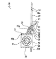
- the lamp unit 7 includes a lens holder 8, a projection lens 9 attached to the front end of the lens holder 8, a reflector 10 that reflects light, a light source unit 11 that is disposed below the reflector 10, and a light source unit 11. And a cooling fan 12 disposed on the lower surface side.
- the projection lens 9 is formed in a substantially hemispherical shape and attached to the lens holder 8.
- the inner surface of the reflector 10 is formed as a reflecting surface 10a.
- the reflector 10 is attached to the upper surface of the light source unit 11.
- the light source unit 11 has a circuit board 13 and a light source 14 mounted on the upper surface of the circuit board 13.
- a light emitting diode LED
- a heat sink 15 is provided below the circuit board 13 of the light source unit 11.
- the cooling fan 12 is disposed inside the heat sink 15.
- a light amount control mechanism 16 is disposed on the front side of the light source unit 11.
- the light quantity control mechanism 16 has a movable shade 17, a support plate 18, a rotating shaft 19, a link member 20, a solenoid 21, and a cover body 22 (see FIGS. 1 and 2).
- the movable shade 17 includes a light amount control unit 23 formed in a substantially circular arc shape, regulation protrusions 24 and 24 that protrude outward (sideward) from the left and right ends of the light amount control unit 23, and a light amount control unit. 23, the inclined surface portion 25 continuously provided on the lower side, the supported portions 26, 26 projecting rearward from the left and right end portions of the inclined surface portion 25, and one end of the inclined surface portion 25 in the left-right direction. And a sliding portion 27 provided.
- the inclined surface portion 25 is inclined so as to be displaced forward as it goes downward.
- a shallow concave portion 25a is formed in the inclined surface portion 25 except for the left and right end portions on the front side.
- the mounting portions 26a and 26a penetrating left and right are formed in the supported portions 26 and 26.
- the rear surface of the sliding portion 27 is provided with a protruding portion 28 (an example of a first sliding contact member) protruding rearward.
- the protrusion 28 is formed, for example, in a substantially hemispherical shape, and the surface 28a is a part of a spherical surface. Note that the shape of the surface 28a is not limited to a part of a spherical surface, and it is sufficient that at least a part is formed in a curved surface.
- Bearings 29 and 29 are attached to the supported portions 26 and 26, respectively.
- the bearing 29 includes a large-diameter portion 29 a and a small-diameter portion 29 b.
- the small-diameter portion 29 b is inserted into the attachment hole 26 a and attached to the supported portion 26, and the large-diameter portion 29 a is disposed outside the supported portion 26.
- the support plate 18 has a base surface portion 30 facing in the front-rear direction and a mounting surface portion 31 protruding forward from the base surface portion 30.
- the base surface portion 30 has a light passage hole 30a and an arrangement hole 30b that are spaced apart from each other in the vertical direction.
- a portion of the base surface portion 30 around the light passage hole 30 a functions as a fixed shade that shields a part of the light emitted from the light source 14.
- bearing pressing pieces 32, 32 protruding rearward are provided apart from each other in the left-right direction.
- the outer portions of the bearing pressing pieces 32, 32 in the left-right direction are provided as light shielding portions 30 c, 30 c, respectively, and the light shielding portions 30 c, 30 c are spaced apart from each other on the left and right. Yes.
- the support plate 18 is provided with shaft mounting pieces 33 and 33 protruding forward at respective outer positions in the left-right direction of the bearing pressing pieces 32 and 32.
- the mounting surface portion 31 protrudes forward from the lower opening edge of the light passage hole 30a.
- a support shaft 34 that protrudes downward is provided at one end of the mounting surface 31 in the left-right direction.
- Rotating shaft 19 is fixed to support plate 18 so as to extend left and right.
- the rotating shaft 19 is inserted into bearings 29 and 29 attached to the movable shade 17, and portions near both left and right ends are inserted into the shaft attaching pieces 33 and 33 from above.
- the rotation shaft 19 is fixed on the front surface side of the support plate 18 by bending and crimping the shaft attachment pieces 33, 33.
- the movable shade 17 has a light amount control unit 23 inserted through the light passage hole 30 a and disposed on the rear side of the support plate 18. It arrange
- the bearings 29 and 29 are in a state where the large diameter portions 29 a and 29 a are in contact with the bearing pressing pieces 32 and 32 of the support plate 18 from the inside, respectively. Thereby, the movement in the left-right direction with respect to the rotating shaft 19 of the movable shade 17 is controlled.
- the movable shade 17 is rotatable with respect to the support plate 18 with the rotation shaft 19 as a fulcrum by fixing the rotation shaft 19 to the support plate 18. Thereby, between the 1st position (refer FIG. 3) which shields a part of light radiate
- the first position is a position for forming a low beam light distribution pattern that illuminates the front of the vehicle at a short distance.
- the restricting protrusions 24 and 24 of the movable shade 17 are in contact with the rear surface of the base surface portion 30 of the support plate 18. State.
- the second position is a position for forming a high beam light distribution pattern that illuminates to the front of a vehicle over a long distance.
- the restricting protrusions 24 and 24 of the movable shade 17 are separated from the base surface portion 30 of the support plate 18 rearward. State.
- a biasing spring 35 which is a torsion coil spring, is attached to the outer peripheral surface of the rotating shaft 19, and both end portions of the biasing spring 35 are engaged with the rear surface of the movable shade 17 and the support plate 18, respectively. Accordingly, the movable shade 17 is urged by the urging spring 35 in a direction to rotate from the second position to the first position. The movable shade 17 is held at the first position by the restricting protrusions 24, 24 being pressed against the rear surface of the base surface portion 30 by the urging force of the urging spring 35.
- the link member 20 has a substantially triangular base portion 36 and a flat sliding contact portion 37 (an example of a second sliding contact member) protruding sideways from the base portion 36 (see FIG. 2). ).
- a connecting shaft portion 36 a that protrudes downward is provided at the front end portion of the base portion 36.
- a supported hole 36b penetrating vertically is formed at the rear end portion of the base portion 36.
- the support shaft 34 is inserted into the supported hole 36 b of the link member 20, and a retaining ring 38 is attached to the lower end portion of the support shaft 34.
- the link member 20 is rotatably supported by the support plate 18 with the support shaft 34 as a fulcrum.
- a part of the link member 20 is disposed so as to pass through the disposition hole 30 b, and the slidable contact portion 37 is brought into contact with the protrusion 28 of the movable shade 17. .
- the solenoid 21 functions as an actuator for rotating the movable shade 17, and includes a yoke case 39, a coil body 40 disposed inside the yoke case 39, and an output shaft 41 movable in the left-right direction. ing.
- the yoke case 39 is formed in a frame shape penetrating in the longitudinal direction.
- the coil body 40 is arranged so that the axial direction coincides with the left-right direction of the lamp unit 7.
- a drive current is supplied to the coil body 40 from a power supply circuit (not shown).
- the output shaft 41 extends so that the axial direction coincides with the left-right direction of the lamp unit 7, and a part of the output shaft 41 protrudes laterally from the yoke case 39.
- An annular coupling groove 41 a is formed in a portion near the tip of the output shaft 41.
- the output shaft 41 is movable in the axial direction according to the supply state of the drive current to the coil body 40.
- the upper surface 39a of the yoke case 39 is attached to the attachment surface 31 of the support plate 18 by screws or the like. In a state where the upper surface portion 39a is attached to the attachment surface portion 31, a part of the solenoid 21 is arranged in the arrangement hole 30b.
- the connecting shaft portion 36a is inserted into the connecting groove 41a of the output shaft 41, and the solenoid 21 and the link member 20 are connected. Therefore, when the output shaft 41 is moved in the axial direction according to the supply state of the drive current to the coil body 40, the link member 20 is rotated with the support shaft 34 as a fulcrum, and the protrusion 28 moves on the sliding contact portion 37. Slide. The movable shade 17 rotates about the rotation shaft 19 according to the contact position of the protrusion 28 with respect to the sliding contact portion 37.
- the cover body 22 is attached to the front side of the support plate 18 by screws or the like. By attaching the cover body 22 to the support plate 18, the solenoid 21 is covered by the cover body 22.
- the lamp unit 7 is supported by the lamp housing 2 in a tiltable manner via an aiming adjusting mechanism (not shown). Accordingly, the lamp unit 7 is tilted in the vertical direction or the horizontal direction of the vehicle headlamp 1 by the operation of the aiming adjustment mechanism, and the optical axis adjustment (initial adjustment) of the light source 14 is performed.
- the lamp unit 7 may be supported by the lamp housing 2 so as to be tiltable in the vertical direction of the vehicle headlamp 1, for example.
- a leveling adjustment mechanism (not shown) is connected to the lamp unit 7, and the lamp unit 7 is tilted in the vertical direction of the vehicle headlamp 1 by the operation of the leveling adjustment mechanism. The direction of the optical axis is adjusted.
- the lamp unit 7 may be rotatable in the left-right direction of the vehicle headlamp 1, for example.
- a swivel mechanism (not shown) is connected to the lamp unit 7, and the lamp unit 7 is rotated in the left-right direction of the vehicle headlamp 1 by the operation of the swivel mechanism, and follows the traveling direction of the vehicle. The direction of is changed.
- the link member 20 is at the first rotation end where the slidable contact portion 37 is located on the front side, and the surface 28 a of the projection 28 provided on the sliding portion 27 of the movable shade 17 and the slidable contact portion 37 abut. (See FIGS. 5 and 6).
- Rotating the movable shade 17 to the second position reduces the amount of light that is emitted from the light source 14 and forms a high beam light distribution pattern that illuminates the front of the vehicle to a long distance.
- the movable shade 17 When the energization of the coil body 40 is stopped, the movable shade 17 is rotated from the second position to the first position around the rotation shaft 19 by the urging force of the urging spring 35. As the movable shade 17 rotates, the link member 20 is rotated, and the output shaft 41 is moved to the moving end in the direction protruding from the yoke case 39 (see FIGS. 3, 5, and 6).
- a part of the light that has passed through the light passage hole 30 a of the support plate 18 passes through the front surface side of the inclined surface portion 25.
- a concave portion 25 a is formed in the inclined surface portion 25.
- the lamp unit 7 includes a movable shade 17, a solenoid 21, and a link member 20.
- the movable shade 17 is rotatable about a rotation shaft 19 and switches the shielding amount of the light emitted from the light source 14 according to the rotation amount.
- the solenoid 21 has an output shaft 41 that can move in the axial direction.
- the link member 20 is connected to the output shaft 41 of the solenoid 21 and is displaced as the output shaft 41 moves.
- the movable shade 17 is provided with a protrusion 28.
- the link member 20 is provided with a sliding contact portion 37 that is in contact with the protrusion 28. When the projection 28 slides on the sliding contact portion 37 due to the displacement of the link member 20, the movable shade 17 rotates around the rotation shaft 19.
- a surface 28a of the protrusion 28 is a curved surface.
- the miniaturized vehicle headlamp 1 including the miniaturized lamp unit 7 can be provided at low cost.
- a protrusion 28 is provided on the sliding portion 27 of the movable shade 17.
- the protrusion may be provided on the sliding contact portion 37 of the link member 20.
- the protrusion 28 and the sliding contact portion 37 are formed integrally or separately from the movable shade 17 or the link member 20 with a material having high sliding property. May be. *
- the direction in which the rotating shaft 19 of the movable shade 17 extends coincides with the direction in which the output shaft 41 of the solenoid 21 moves (the left-right direction of the lamp unit 7). According to such a configuration, it is not necessary to secure a moving space for the output shaft 41 in the direction orthogonal to the direction in which the rotation shaft 19 extends (the front-rear direction of the lamp unit 7). Therefore, it is possible to reduce the size of the lamp unit 7 in the front-rear direction while improving the operation efficiency of the movable shade 17.
- the surface 28a of the protrusion 28 is a part of a spherical surface. According to such a structure, the contact area of the protrusion 28 and the sliding contact portion 37 at the time of sliding contact is small, and the link member 20 and the movable shade 17 interlock more smoothly. Therefore, the operation efficiency of the movable shade 17 is further improved.
- the sliding contact portion 37 has a flat surface with which the surface 28a of the protrusion 28 contacts. According to such a configuration, since the protrusion 28 and the sliding contact portion 37 are always in point contact, the link member 20 and the movable shade 17 are more smoothly interlocked. Therefore, the operation efficiency of the movable shade 17 is further improved.
- the upper end portion of the movable shade 17 is disposed on the front side of the rotating shaft 19, and the lower end portion of the movable shade 17 is disposed on the rear side of the rotating shaft 19.
- the rotation shaft 19 is disposed between the upper end portion and the lower end portion of the movable shade 17. Therefore, a good weight balance of the movable shade is ensured without additionally providing a counterweight or the like. Thereby, the small thing with small driving force can be used as the solenoid 21 for rotating the movable shade 17. FIG. Therefore, the lamp unit 7 can be reduced in size while suppressing an increase in the weight of the movable shade 17.
- a light passage hole of the support plate 18 is provided in order to secure a rotation space at the upper end portion or the lower end portion of the movable shade 17. It is necessary to increase 30a.
- the lower end portion of the movable shade 17 may be disposed on the rear side of the rotating shaft 19 and the upper end portion may be disposed on the front side of the rotating shaft 19.
- the lower end portion of the movable shade 17 is disposed behind the light amount control unit 23.
- Contact with a part of the light source unit 11 located on the side can be avoided. Therefore, when the lamp unit 7 is reduced in size while suppressing an increase in the weight of the movable shade 17, it is possible to effectively use the space and facilitate the design.
- the lamp unit 7 includes a support plate 18.
- the support plate 18 includes a pair of light shielding portions 30 c that shields part of the light emitted from the light source 14.
- the pair of light shielding portions 30 c are arranged on the rear side of the movable shade 17 so as to be separated in the direction (left-right direction) in which the rotation shaft 19 extends.
- a biasing spring 35 that biases the movable shade 17 toward the first position is located on the rear side of the movable shade 17. According to such a configuration, it is possible to avoid that the light that has passed through the light passage hole 30a of the support plate 18 is reflected and shielded by the urging spring 35 or the member that supports the urging spring 35. Therefore, an increase in the weight of the movable shade 17 is suppressed, and a good light distribution pattern can be formed while the lamp unit 7 is downsized.
- vehicle headlamp 1 having the reflector 10 is shown as an example of the embodiment, the present invention can also be applied to a so-called direct-type vehicle headlamp having no reflector. .
- an appropriate actuator other than the solenoid 21 can be used.
Landscapes
- Engineering & Computer Science (AREA)
- General Engineering & Computer Science (AREA)
- Physics & Mathematics (AREA)
- Microelectronics & Electronic Packaging (AREA)
- Optics & Photonics (AREA)
- Mechanical Engineering (AREA)
- Non-Portable Lighting Devices Or Systems Thereof (AREA)
- Lighting Device Outwards From Vehicle And Optical Signal (AREA)
Abstract
可動シェード17は、回動軸19を中心に回動可能とされ、回動量に応じて光源から出射された光の遮蔽量を切り替える。ソレノイド21は、軸方向へ移動可能な出力軸41を有する。リンク部材20は、出力軸41に連結され、出力軸41の移動に伴って変位する。突部28は、可動シェード17に設けられる。摺接部37は、リンク部材20に設けられ、突部28に当接される。リンク部材20の変位に応じて突部28が摺接部37上を摺動することによって、可動シェード17が回動軸19を中心に回動するように構成されている。突部28の表面28aは、曲面とされている
Description
本発明は車輌に搭載される灯具ユニットに関する。また本発明は、当該灯具ユニットを備える車輌用前照灯に関する。
車輌用前照灯には、例えば、カバーとランプハウジングによって構成された灯具外筐の内部に、光源等を有する灯具ユニットが配置されたものがある。
このような灯具ユニットには、光源から出射された光量を制御する光量制御機構が設けられ、光量制御機構が光源から出射された光の遮蔽量を変更する可動シェードと可動シェードを動作させるソレノイドとを有するものがある(例えば、特許文献1の図4参照)。
特許文献1に記載された車輌用前照灯にあっては、前方側に配置されたソレノイドの出力軸とソレノイドの後方に配置された可動シェードとがワイヤー状のアーム(リンク部材)によって連結されている。アームは、一端部が出力軸に回転可能に連結され、他端部(折曲部)が可動シェードの係合部に対して摺動自在に当接されている。
ソレノイドの出力軸が左右方向へ移動されるとアームが回転され、アームの折曲部が可動シェードの係合部上を摺動する。これにより、可動シェードが左右に延びる回動軸を中心として回動される。
可動シェードが第1の位置に回動されることにより車輌の近距離前方を照明するロービームモードに切り替えられ、可動シェードが第2の位置に回動されることにより車輌の遠距離前方まで照明するハイビームモードに切り替えられる。
ところが、特許文献1に記載された車輌用前照灯にあっては、出力軸が左右方向へ移動されてアームが回転されたときに、アームの折曲部が係合部の端縁、即ち、角張った部分上を摺動する。
従って、角張った部分同士が摺接するため、滑らかな連動性を確保することが困難であり、動作効率の低下を来している。このように動作効率が低い場合には、その分、駆動力の大きなソレノイドを用いる必要が生じ、ソレノイドの大型化やコストの上昇を来たすと言う問題がある。
そこで、本発明は、可動シェードの動作効率を向上することを第1の課題とする。
また、特許文献1に記載された灯具ユニットのように光源から出射された光の制御を行う可動シェードが設けられたタイプにおいて、例えば、回動軸の前側や後側に可動シェードの大部分が配置されるような構成である場合には、可動シェードの重量バランスが悪くなる(重心を回転軸上に配置しにくくなる)。この場合、振動などによって可動シェードが回転してしまうことを防止するために、可動シェードを所定位置に留めておくバネなどの付勢力を強くする必要が生ずる。この付勢力に抗して可動シェードを回動させるためには、駆動力の大きな大型のアクチュエータを使用する必要が生じ、灯具ユニットの小型化や製造コストの低減に支障を来してしまう。
また、回動軸の前側や後側に可動シェードの大部分が配置される構成の場合、重量バランスを確保するために、可動シェードにカウンターウエイトを取り付ける必要が生ずる。しかしながら、この場合には可動シェードの全体重量が大きくなってしまい、やはり駆動力の大きなアクチュエーターを用いる必要がある。
そこで、本発明は、可動シェードの重量増加を抑制しつつ、灯具ユニットを小型化することを第2の課題とする。
上記第1の課題を達成するために、本発明がとりうる第1の態様は、車輌に搭載される灯具ユニットであって、
光源と、
回動軸を中心に回動可能とされ、回動量に応じて前記光源から出射された光の遮蔽量を切り替える可動シェードと、
軸方向へ移動可能な出力軸を有するアクチュエーターと、
前記出力軸に連結され、前記出力軸の移動に伴って変位するリンク部材と、
前記可動シェードに設けられた第1摺接部材と、
前記リンク部材に設けられ、前記第1摺接部材に当接された第2摺接部材と、
を備えており、
前記リンク部材の変位に応じて前記第1摺接部材が前記第2摺接部材上を摺動することによって、前記可動シェードが前記回動軸を中心に回動するように構成されており、
前記第1摺接部材と前記第2摺接部材の一方の表面は、曲面とされている。
光源と、
回動軸を中心に回動可能とされ、回動量に応じて前記光源から出射された光の遮蔽量を切り替える可動シェードと、
軸方向へ移動可能な出力軸を有するアクチュエーターと、
前記出力軸に連結され、前記出力軸の移動に伴って変位するリンク部材と、
前記可動シェードに設けられた第1摺接部材と、
前記リンク部材に設けられ、前記第1摺接部材に当接された第2摺接部材と、
を備えており、
前記リンク部材の変位に応じて前記第1摺接部材が前記第2摺接部材上を摺動することによって、前記可動シェードが前記回動軸を中心に回動するように構成されており、
前記第1摺接部材と前記第2摺接部材の一方の表面は、曲面とされている。
このような構成によれば、出力軸が移動されたときに摺接する第1摺接部材と第2摺接部材の一方の表面が曲面とされているため、可動シェードとリンク部材が滑らかに連動する。したがって、可動シェードの動作効率が向上する。
前記回動軸の延びる方向と、前記出力軸の移動方向が一致している構成としてもよい。
このような構成によれば、回動軸の延びる方向と直交する方向において出力軸の移動スペースを確保する必要がない。したがって、可動シェードの動作効率を向上しつつ、可動シェードの回動軸が延びる方向と直交する方向における灯具ユニットの小型化が可能である。
前記曲面は、球面の一部とされている構成としてもよい。
このような構成によれば、摺接時における第1摺接部材と第2摺接部材の接触面積が小さく、リンク部材と可動シェードがより滑らかに連動する。したがって、可動シェードの動作効率がより向上する。
前記第1摺接部材と前記第2摺接部材の他方は、前記曲面が接触する平面を有している構成としてもよい。
このような構成によれば、第1摺接部材と第2摺接部材の一方が、他方に対して常に点接触するため、リンク部材と可動シェードがより滑らかに連動する。したがって、可動シェードの動作効率がより向上する。
上記第1の課題を達成するために、本発明がとりうる第2の態様は、車輌に搭載される前照灯であって、
少なくとも一方に開口を有するランプハウジングと、
前記開口を覆うことにより前記ランプハウジングとともに灯室を区画するカバーと、
上記第1の態様に係る灯具ユニットと、
を備えている。
少なくとも一方に開口を有するランプハウジングと、
前記開口を覆うことにより前記ランプハウジングとともに灯室を区画するカバーと、
上記第1の態様に係る灯具ユニットと、
を備えている。
このような構成によれば、可動シェードの動作効率が向上した灯具ユニットを備えているため、小型化された車輌用前照灯を低コストで提供できる。
上記の第2の課題を達成するために、本発明がとりうる第3の態様は、車両に搭載される灯具ユニットであって、
光源と、
回動軸を中心に回動可能とされ、回動量に応じて前記光源から出射された光の遮蔽量を切り替える可動シェードと、
前記可動シェードを回動させるアクチュエーターと、
を備えており、
前記可動シェードの上端部と下端部の一方が前記回動軸の前側に配置され、他方が前記回動軸の後側に配置されている。
光源と、
回動軸を中心に回動可能とされ、回動量に応じて前記光源から出射された光の遮蔽量を切り替える可動シェードと、
前記可動シェードを回動させるアクチュエーターと、
を備えており、
前記可動シェードの上端部と下端部の一方が前記回動軸の前側に配置され、他方が前記回動軸の後側に配置されている。
このような構成によれば、可動シェードの上端部と下端部が回動軸を挟んだ前後に配置される。換言すると、可動シェードの上端部と下端部の間に回動軸が配置される。従って、カウンターウェイトなどを追加的に設けることなく、可動シェードの良好な重量バランスが確保される。これにより、可動シェードを回動させるためのアクチュエーターとして駆動力の小さな小型のものを使用できる。したがって、可動シェードの重量増加を抑制しつつ、灯具ユニットを小型化できる。
前記可動シェードの上端部が前記回動軸の後側に配置されており、前記可動シェードの下端部が前記回動軸の前側に配置されている構成としてもよい。
このような構成によれば、可動シェードの下端部が後側に位置する光源などに接触することを回避できる。したがって、可動シェードの重量増加を抑制しつつ灯具ユニットを小型化するにあたって、スペースの有効活用及び設計の容易化が可能である。
前記回動軸を支持する支持プレートを備えており、
前記支持プレートは、前記光源から出射された光の一部を遮蔽する一対の遮光部を備えており、
前記一対の遮光部は、前記可動シェードの後側において前記回動軸の延びる方向に離隔して配置されている構成としてもよい。
前記支持プレートは、前記光源から出射された光の一部を遮蔽する一対の遮光部を備えており、
前記一対の遮光部は、前記可動シェードの後側において前記回動軸の延びる方向に離隔して配置されている構成としてもよい。
このような構成によれば、可動シェードの位置に拘わらず遮光部によって光が遮蔽される。したがって、可動シェードの重量増加を抑制しつつ灯具ユニットを小型化するにあたって、可動シェードの周辺を通過する光による配光パターンへの影響を抑制できる。
前記可動シェードを一方向へ付勢する付勢バネが設けられ、
前記付勢バネは、前記可動シェードの後側に配置されている構成としてもよい。
前記付勢バネは、前記可動シェードの後側に配置されている構成としてもよい。
このような構成によれば、可動シェードの前側へ出射された光が付勢バネや付勢バネを支持する部材により反射及び遮蔽されることを回避できる。したがって、可動シェードの重量増加を抑制し、灯具ユニットを小型化しながらも、良好な配光パターンを形成できる。
上記第2の課題を達成するために、本発明がとりうる第4の態様は、車輌に搭載される前照灯であって、
少なくとも一方に開口を有するランプハウジングと、
前記開口を覆うことにより前記ランプハウジングとともに灯室を区画するカバーと、
上記第3の態様に係る灯具ユニットと、
を備えている。
少なくとも一方に開口を有するランプハウジングと、
前記開口を覆うことにより前記ランプハウジングとともに灯室を区画するカバーと、
上記第3の態様に係る灯具ユニットと、
を備えている。
このような構成によれば、可動シェードの重量増加を抑制しつつ小型化された灯具ユニットを備えているため、小型化された車輌用前照灯を低コストで提供できる。
以下に、本発明に係る車輌用前照灯を実施するための形態について添付図面を参照して説明する。
車輌用前照灯1は、それぞれ車体の前端部における左右両端部に取り付けられて配置されている。
車輌用前照灯1は前方に開口された凹部を有するランプハウジング2とランプハウジング2の開口を閉塞するカバー3とを備えている(図1参照)。ランプハウジング2とカバー3によって灯具外筐4が構成され、灯具外筐4の内部空間は灯室5として区画されている。
取付孔2aは、ランプハウジング2の後端部を前後に貫通している。取付孔2aにはバックカバー6が取り付けられている。
灯室5には灯具ユニット7が配置されている。灯具ユニット7は、レンズホルダー8と、レンズホルダー8の前端部に取り付けられた投影レンズ9と、光を反射するリフレクター10と、リフレクター10の下方に配置された光源ユニット11と、光源ユニット11の下面側に配置された冷却ファン12とを有している。
投影レンズ9は、略半球状に形成されレンズホルダー8に取り付けられている。
リフレクター10の内面は、反射面10aとして形成されている。リフレクター10は、光源ユニット11の上面に取り付けられている。
光源ユニット11は、回路基板13と、回路基板13の上面に搭載された光源14とを有している。光源14としては、例えば、発光ダイオード(LED)が用いられる。光源ユニット11の回路基板13の下側には、ヒートシンク15が設けられている。冷却ファン12はヒートシンク15の内側に配置されている。
光源ユニット11の前側には、光量制御機構16が配置されている。
光量制御機構16は、可動シェード17と、支持プレート18と、回動軸19と、リンク部材20と、ソレノイド21と、カバー体22を有している(図1及び図2参照)。
可動シェード17は、略円弧面状に形成された光量制御部23と、光量制御部23の左右両端部からそれぞれ外方(側方)へ突出された規制突部24、24と、光量制御部23の下側に連続して設けられた傾斜面部25と、傾斜面部25の左右両端部からそれぞれ後方へ突出された被支持部26、26と、傾斜面部25の左右方向における一端に連続して設けられた摺動部27とを有している。
傾斜面部25は下方へ行くに従って前方へ変位するように傾斜されている。傾斜面部25には、前面側における左右両端部を除く部分に浅い凹部25aが形成されている。
被支持部26、26には左右に貫通された取付孔26a、26aが形成されている。
摺動部27の後面には、後方へ突出された突部28(第1摺接部材の一例)が設けられている。突部28は、例えば、略半球状に形成され、表面28aが球面の一部とされている。尚、表面28aの形状は球面の一部に限られることはなく、少なくとも一部が曲面に形成されていればよい。
被支持部26、26には、それぞれ軸受29、29が取り付けられている。軸受29は大径部29aと小径部29bから成り、小径部29bが取付孔26aに挿入されて被支持部26に取り付けられ、大径部29aが被支持部26の外側に配置されている。
支持プレート18は、前後方向を向くベース面部30とベース面部30から前方へ突出された取付面部31とを有している。
ベース面部30は、上下に離隔して形成された光通過孔30aと配置孔30bを有している。ベース面部30のうち光通過孔30aの周囲の部分は、光源14から出射される光の一部を遮蔽する固定シェードとして機能する。光通過孔30aの開口縁には、後方へ突出された軸受押さえ片32、32が左右に離隔して設けられている。
支持プレート18のベース面部30のうち、軸受押さえ片32、32の左右方向におけるそれぞれ外側の部分は、それぞれ遮光部30c、30cとして設けられ、遮光部30c、30cは左右に離隔して配置されている。
支持プレート18には、軸受押さえ片32、32の左右方向におけるそれぞれ外側の位置に前方へ突出された軸取付片33、33が設けられている。
取付面部31は、光通過孔30aの下側開口縁から前方へ突出されている。取付面部31の左右方向における一端部には、下方へ突出された支持軸34が設けられている。
回動軸19は左右に延びる状態で支持プレート18に固定されている。回動軸19は、可動シェード17に取り付けられた軸受29、29に挿入され、左右両端寄りの部分が軸取付片33、33に上方から挿入される。軸取付片33、33が屈曲されて加締められることにより、回動軸19は、支持プレート18の前面側において固定される。
回動軸19が支持プレート18に固定された状態において、可動シェード17は、光量制御部23が光通過孔30aを挿通されて支持プレート18の後側に配置され、下側に位置する部分が支持プレート18の前側に配置される(図3及び図4参照)。従って、可動シェード17は、上端部を含む上側の部分が回動軸19の後側に配置され、下端部を含む下側の部分が回動軸19の前側に配置される。軸受29、29は、大径部29a、29aがそれぞれ支持プレート18の軸受押さえ片32、32に内側から接した状態とされる。これにより、可動シェード17の回動軸19に対する左右方向における移動が規制される。
可動シェード17は、回動軸19が支持プレート18に固定されることにより、回動軸19を支点として支持プレート18に対して回動可能とされている。これにより、光源14から出射された光の一部を遮蔽する第1の位置(図3参照)と、第1の位置より遮蔽量が少なくなる第2の位置(図4参照)との間で回動可能とされている。第1の位置は、車輌の近距離前方を照明するロービーム配光パターンを形成するための位置であり、可動シェード17の規制突部24、24が支持プレート18のベース面部30の後面に接した状態とされる。第2の位置は、車輌の遠距離前方まで照明するハイビーム配光パターンを形成するための位置であり、可動シェード17の規制突部24、24が支持プレート18のベース面部30から後方に離隔した状態とされる。
回動軸19の外周面には、捩じりコイルバネである付勢バネ35が装着され、付勢バネ35の両端部がそれぞれ可動シェード17の後面と支持プレート18に係合される。従って、可動シェード17は、付勢バネ35によって第2の位置から第1の位置へ向けて回動する方向へ付勢される。可動シェード17は、付勢バネ35の付勢力によって規制突部24、24がベース面部30の後面に押し付けられて、第1の位置に保持される。
リンク部材20は、略三角形状のベース部36と、ベース部36から側方へ突出された平板状の摺接部37(第2摺接部材の一例)とを有している(図2参照)。ベース部36の前端部には、下方へ突出された連結軸部36aが設けられている。ベース部36の後端部には、上下に貫通する被支持孔36bが形成されている。
リンク部材20の被支持孔36bに支持軸34が挿入され、支持軸34の下端部に止め輪38が取り付けられている。これにより、リンク部材20は、支持軸34を支点として支持プレート18に回動自在に支持される。リンク部材20が支持プレート18に支持された状態においては、リンク部材20の一部が配置孔30bを挿通するように配置され、摺接部37が可動シェード17の突部28に当接される。
ソレノイド21は、可動シェード17を回動させるアクチュエーターとして機能し、ヨークケース39と、ヨークケース39の内部に配置されたコイル体40と、左右方向へ移動可能とされた出力軸41とを有している。
ヨークケース39は、横長の前後に貫通された枠状に形成されている。
コイル体40は、軸方向が灯具ユニット7の左右方向に一致するように配置されている。コイル体40には図示しない電源回路から駆動電流が供給される。
出力軸41は、軸方向が灯具ユニット7の左右方向に一致するように延び、一部がヨークケース39から側方へ突出されている。出力軸41の先端寄りの部分には、環状の連結溝41aが形成されている。出力軸41はコイル体40に対する駆動電流の供給状態に応じて軸方向へ移動可能とされている。
ヨークケース39の上面部39aは、支持プレート18の取付面部31にネジ止め等によって取り付けられる。上面部39aが取付面部31に取り付けられた状態においては、ソレノイド21の一部が配置孔30bに配置される。
出力軸41の連結溝41aに連結軸部36aが挿入されて、ソレノイド21とリンク部材20が連結される。従って、コイル体40に対する駆動電流の供給状態に応じて出力軸41が軸方向へ移動されると、リンク部材20が支持軸34を支点として回動され、突部28が摺接部37上を摺動する。突部28の摺接部37に対する接触位置に応じて、可動シェード17が回動軸19を中心に回動する。
カバー体22は、支持プレート18の前面側にネジ止め等によって取り付けられる。カバー体22が支持プレート18に取り付けられることにより、ソレノイド21がカバー体22によって覆われる。
灯具ユニット7は、図示しないエイミング調整機構を介してランプハウジング2に傾動自在に支持されている。従って、エイミング調整機構の動作により、灯具ユニット7が車輌用前照灯1の上下方向又は左右方向へ傾動され、光源14の光軸調整(初期調整)が行われる。
また、灯具ユニット7は、例えば、車輌用前照灯1の上下方向へ傾動可能となるようにランプハウジング2に支持されていてもよい。この場合には、灯具ユニット7に図示しないレベリング調整機構が連結され、レベリング調整機構の動作によって灯具ユニット7が車輌用前照灯1の上下方向へ傾動され、車載物の重量に応じて光源14の光軸の向きが調整される。
さらに、灯具ユニット7は、例えば、車輌用前照灯1の左右方向へ回動可能にされていてもよい。この場合には、灯具ユニット7に図示しないスイブル機構が連結され、スイブル機構の動作によって灯具ユニット7が車輌用前照灯1の左右方向へ回動され、車輌の走行方向に追従して光軸の向きが変更される。
ソレノイド21のコイル体40に駆動電流が供給されていない状態においては、付勢バネ35に付勢されている可動シェード17は規制突部24、24が支持プレート18のベース面部30に押し付けられて、第1の位置に保持されている(図3及び図5参照)。このときソレノイド21の出力軸41は、ヨークケース39から突出される方向における移動端に配置されている。
リンク部材20は、摺接部37が前方側に位置する第1の回動端にあり、可動シェード17の摺動部27に設けられた突部28の表面28aと摺接部37が当接した状態とされている(図5及び図6参照)。
可動シェード17が第1の位置にある状態において、光源14から光が出射されると、可動シェード17によって光の一部が遮蔽され、遮蔽されなかった光が投影レンズ9に入射される。投影レンズ9によって可動シェード17の端縁形状が投影されて、車輌の前方近距離を照明するロービームの配光パターンが形成される。
ソレノイド21のコイル体40に通電が行われると、出力軸41がヨークケース39に引き込まれる方向へ移動され、リンク部材20が支持軸34を中心に回動(変位の一例)する。リンク部材20に応じて可動シェード17の突部28がリンク部材20の摺接部37上を摺動し、可動シェード17が、回動軸19を中心として付勢バネ35の付勢力に反して第1の位置から第2の位置まで回動される(図4、図7及び図8参照)。
可動シェード17が第2の位置まで回動されることにより、光源14から出射される光の遮蔽量が少なくなり、車輌の前方を遠距離まで照明するハイビームの配光パターンが形成される。
コイル体40に対する通電が停止されると、付勢バネ35の付勢力によって、可動シェード17が回動軸19を中心として第2の位置から第1の位置まで回動される。可動シェード17の回動に伴ってリンク部材20が回動され、出力軸41がヨークケース39から突出される方向における移動端まで移動される(図3、図5及び図6参照)。
尚、支持プレート18の光通過孔30aを通過した光の一部は、傾斜面部25の前面側を通過する。傾斜面部25には凹部25aが形成されている。凹部25aが形成されることによって、傾斜面部25の前面側を通過する光が可動シェード17により不必要に反射及び遮蔽されることが防止される。
本実施形態に係る灯具ユニット7は、可動シェード17、ソレノイド21、およびリンク部材20を備えている。可動シェード17は、回動軸19を中心に回動可能とされており、回動量に応じて光源14から出射された光の遮蔽量を切り替える。ソレノイド21は、軸方向へ移動可能な出力軸41を有する。リンク部材20は、ソレノイド21の出力軸41に連結されており、出力軸41の移動に伴って変位する。可動シェード17には、突部28が設けられている。リンク部材20には、突部28に当接された摺接部37が設けられている。リンク部材20の変位によって突部28が摺接部37上を摺動することによって、可動シェード17が回動軸19を中心に回動するように構成されている。突部28の表面28aは、曲面とされている。
このような構成によれば、出力軸41が移動されたときに摺接部37上を摺動する突部28の表面28aが曲面とされているため、リンク部材20の変位に対して可動シェード17が滑らかに連動する。したがって、ソレノイド21による可動シェード17の動作効率が向上する。
これにより、ソレノイド21として駆動力の小さな小型のものを用いることができる。また、ソレノイド21の小型化により、可動シェード17を付勢する付勢バネ35をソレノイド21の駆動力に応じて小さくすることが可能になり、付勢バネ35のコストも低減できる。結果として、小型化された灯具ユニット7を備える小型化された車輌用前照灯1を低コストで提供できる。
本実施形態においては、可動シェード17の摺動部27に突部28が設けられている。逆に、突部がリンク部材20の摺接部37に設けられてもよい。
また、突部28と摺接部37の摺動性を高めるために、摺動性の高い材料で突部28や摺接部37を可動シェード17又はリンク部材20と一体又は別体で形成してもよい。
本実施形態においては、可動シェード17の回動軸19が延びる方向と、ソレノイド21の出力軸41が移動する方向が一致している(灯具ユニット7の左右方向)。このような構成によれば、回動軸19の延びる方向と直交する方向(灯具ユニット7の前後方向)において出力軸41の移動スペースを確保する必要がない。したがって、可動シェード17の動作効率を向上しつつ、前後方向における灯具ユニット7の小型化が可能である。
本実施形態においては、突部28の表面28aは、球面の一部とされている。このような構成によれば、摺接時における突部28と摺接部37の接触面積が小さく、リンク部材20と可動シェード17がより滑らかに連動する。したがって、可動シェード17の動作効率がより向上する。
本実施形態においては、摺接部37は、突部28の表面28aが接触する平面を有している。このような構成によれば、突部28と摺動接触部37が常に点接触するため、リンク部材20と可動シェード17がより滑らかに連動する。したがって、可動シェード17の動作効率がより向上する。
本実施形態においては、可動シェード17の上端部が回動軸19の前側に配置され、可動シェード17の下端部が回動軸19の後側に配置されている。
このような構成によれば、可動シェード17の上端部と下端部の間に回動軸19が配置される。従って、カウンターウェイトなどを追加的に設けることなく、可動シェードの良好な重量バランスが確保される。これにより、可動シェード17を回動させるためのソレノイド21として駆動力の小さな小型のものを使用できる。したがって、可動シェード17の重量増加を抑制しつつ、灯具ユニット7を小型化できる。
さらに、可動シェード17の大部分が支持プレート18の前側又は後側に位置する場合には、可動シェード17の上端部又は下端部の回動スペースを確保するために、支持プレート18の光通過孔30aを大きくする必要が生じる。
しかしながら、上記の構成によれば、可動シェード17の回動時に可動シェード17の上端部と下端部が支持プレート18を挟んだ前後において移動するため、支持プレート18に可動シェード17の上端部と下端部の回動スペースを確保するための空間を形成する必要がなく、光源14から出射された光が支持プレート18より前側へ漏れることを抑制できる。
逆に、可動シェード17の下端部が回動軸19の後側に配置され、上端部が回動軸19の前側に配置されるように構成してもよい。
但し、可動シェード17の上端部が回動軸19の後側に配置され、下端部が回動軸19の前側に配置される構成の場合、可動シェード17の下端部が光量制御部23の後側に位置する光源ユニット11の一部に接触することを回避できる。したがって、可動シェード17の重量増加を抑制しつつ灯具ユニット7を小型化するにあたって、スペースの有効活用及び設計の容易化が可能である。
本実施形態に係る灯具ユニット7は、支持プレート18を備えている。支持プレート18は、光源14から出射された光の一部を遮蔽する一対の遮光部30cを備えている。一対の遮光部30cは、可動シェード17の後側において回動軸19の延びる方向(左右方向)に離隔して配置されている。可動シェード17が第2の位置にある状態において光源14から光が出射された場合、可動シェード17の下端部の位置が、可動シェード17が第1の位置にある状態よりも上方に移動されるため、可動シェード17の下側を光が通過し易い状態になる。このとき可動シェード17の下側における左右両端部から光が前方へ通過すると配光パターンに影響を及ぼす。上記の構成によれば、可動シェード17の傾斜面部25の後側における左右両端部に配置された遮光部30cによってそのような光が遮蔽される。従って、可動シェード17の重量増加を抑制しつつ灯具ユニット7を小型化するにあたって、可動シェード17の下側を通過する光による配光パターンへの影響を抑制できる。
本実施形態においては、可動シェード17を第1の位置へ向けて(一方向の一例)付勢する付勢バネ35が可動シェード17の後側に位置されている。このような構成によれば、支持プレート18の光通過孔30aを通過された光が付勢バネ35や付勢バネ35を支持する部材により反射及び遮蔽されることを回避できる。したがって、可動シェード17の重量増加を抑制し、灯具ユニット7を小型化しながらも、良好な配光パターンを形成できる。
上記した発明を実施するための最良の形態において示した各部の形状及び構造は、何れも本発明を実施するに際して行う具体化の一例を示したものにすぎず、これらによって本発明の技術的範囲が限定的に解釈されることはない。
例えば、リフレクター10を有する車輌用前照灯1を一実施形態の例として示したが、本発明は、リフレクターを有さない所謂直射型の車輌用前照灯にも適用することが可能である。
可動シェード17を回動させることができば、ソレノイド21以外にも適宜のアクチュエーターを用いることができる。例えば、モータと歯車機構により出力軸の位置が変化するアクチュエーターを用いてもよい。
本出願は、2013年1月28日に提出された日本国特許出願2013-013405、および2013年1月28日に提出された日本国特許出願2013-013406に基づくものであり、その内容はここに参照として取り込まれる。
Claims (5)
- 車輌に搭載される灯具ユニットであって、
光源と、
回動軸を中心に回動可能とされ、回動量に応じて前記光源から出射された光の遮蔽量を切り替える可動シェードと、
軸方向へ移動可能な出力軸を有するアクチュエーターと、
前記出力軸に連結され、前記出力軸の移動に伴って変位するリンク部材と、
前記可動シェードに設けられた第1摺接部材と、
前記リンク部材に設けられ、前記第1摺接部材に当接された第2摺接部材と、
を備えており、
前記リンク部材の変位に応じて前記第1摺接部材が前記第2摺接部材上を摺動することによって、前記可動シェードが前記回動軸を中心に回動するように構成されており、
前記第1摺接部材と前記第2摺接部材の一方の表面は、曲面とされている、車輌用灯具ユニット。 - 前記回動軸の延びる方向と、前記出力軸の移動方向が一致している、請求項1に記載の車輌用灯具ユニット。
- 前記曲面は、球面の一部とされている、請求項1又は請求項2に記載の車輌用灯具ユニット。
- 前記第1摺接部材と前記第2摺接部材の他方は、前記曲面が接触する平面を有している、請求項1から請求項3のいずれか一項に記載の車輌用灯具ユニット。
- 車輌に搭載される前照灯であって、
少なくとも一方に開口を有するランプハウジングと、
前記開口を覆うことにより前記ランプハウジングとともに灯室を区画するカバーと、
前記灯室に配置された請求項1から請求項4のいずれか一項に記載の車輌用灯具ユニットと、
を備えている、車輌用前照灯。
Priority Applications (3)
| Application Number | Priority Date | Filing Date | Title |
|---|---|---|---|
| CN201480006413.9A CN104956146B (zh) | 2013-01-28 | 2014-01-27 | 车辆用灯具单元和车辆用前照灯 |
| US14/763,680 US9528677B2 (en) | 2013-01-28 | 2014-01-27 | Vehicle lamp unit and vehicle headlamp |
| EP14743455.9A EP2949988B1 (en) | 2013-01-28 | 2014-01-27 | Vehicle lighting unit, and vehicle headlight |
Applications Claiming Priority (4)
| Application Number | Priority Date | Filing Date | Title |
|---|---|---|---|
| JP2013013406A JP6153332B2 (ja) | 2013-01-28 | 2013-01-28 | 車輌用前照灯 |
| JP2013-013406 | 2013-01-28 | ||
| JP2013013405A JP6147510B2 (ja) | 2013-01-28 | 2013-01-28 | 車輌用前照灯 |
| JP2013-013405 | 2013-01-28 |
Publications (1)
| Publication Number | Publication Date |
|---|---|
| WO2014115875A1 true WO2014115875A1 (ja) | 2014-07-31 |
Family
ID=51227663
Family Applications (1)
| Application Number | Title | Priority Date | Filing Date |
|---|---|---|---|
| PCT/JP2014/051688 Ceased WO2014115875A1 (ja) | 2013-01-28 | 2014-01-27 | 車輌用灯具ユニット、および車輌用前照灯 |
Country Status (4)
| Country | Link |
|---|---|
| US (1) | US9528677B2 (ja) |
| EP (1) | EP2949988B1 (ja) |
| CN (1) | CN104956146B (ja) |
| WO (1) | WO2014115875A1 (ja) |
Cited By (1)
| Publication number | Priority date | Publication date | Assignee | Title |
|---|---|---|---|---|
| WO2018135615A1 (ja) * | 2017-01-20 | 2018-07-26 | 市光工業株式会社 | 車両用灯具 |
Families Citing this family (7)
| Publication number | Priority date | Publication date | Assignee | Title |
|---|---|---|---|---|
| US10180227B2 (en) * | 2015-09-24 | 2019-01-15 | Hyundai Motor Company | Apparatus for driving headlamp shield |
| US9909747B2 (en) * | 2015-11-06 | 2018-03-06 | Ford Global Technologies, Llc | Vehicle lighting assembly with retractable cover providing daylight running lamp |
| FR3046834B1 (fr) * | 2016-01-20 | 2020-07-03 | Aml Systems | Mecanisme de coupure pour projecteur de vehicule automobile, a barrette de coupure amovible. |
| JP6770347B2 (ja) | 2016-06-27 | 2020-10-14 | 株式会社小糸製作所 | 車両用前照灯 |
| JP2020021665A (ja) * | 2018-08-02 | 2020-02-06 | 市光工業株式会社 | 車両用灯具 |
| JP7306223B2 (ja) * | 2019-10-30 | 2023-07-11 | 市光工業株式会社 | 車両用前照灯の可動シェード機構及び車両用前照灯 |
| US12092284B2 (en) * | 2022-12-29 | 2024-09-17 | Sonar Auto Parts Co., Ltd. | Vehicle lamp having switching structure for low-beam and high-beam headlights |
Citations (3)
| Publication number | Priority date | Publication date | Assignee | Title |
|---|---|---|---|---|
| JPH09512623A (ja) * | 1995-02-28 | 1997-12-16 | ジンテーズ アクチエンゲゼルシャフト,クール | 回転運動を往復運動に変換する伝動装置 |
| JP2007213938A (ja) | 2006-02-08 | 2007-08-23 | Stanley Electric Co Ltd | 車両前照灯及びその遮光シャッタ駆動装置 |
| JP2012190597A (ja) * | 2011-03-09 | 2012-10-04 | Koito Mfg Co Ltd | 車輌用前照灯 |
Family Cites Families (13)
| Publication number | Priority date | Publication date | Assignee | Title |
|---|---|---|---|---|
| JP2001349406A (ja) | 2000-06-06 | 2001-12-21 | Noritake Co Ltd | カム構造 |
| JP4008261B2 (ja) * | 2001-06-15 | 2007-11-14 | 株式会社小糸製作所 | 車両用前照灯 |
| CN2745788Y (zh) * | 2004-09-22 | 2005-12-14 | Aca实业公司 | 远近灯切换装置 |
| JP2006202694A (ja) * | 2005-01-24 | 2006-08-03 | Koito Mfg Co Ltd | 車両用前照灯 |
| JP4527639B2 (ja) | 2005-09-09 | 2010-08-18 | 株式会社小糸製作所 | 車両用前照灯 |
| JP4772438B2 (ja) | 2005-09-16 | 2011-09-14 | Ntn株式会社 | リンク作動装置 |
| JP4669434B2 (ja) | 2006-04-24 | 2011-04-13 | 株式会社小糸製作所 | 車両用前照灯 |
| JP5414246B2 (ja) | 2008-11-19 | 2014-02-12 | 株式会社小糸製作所 | 車両用前照灯 |
| US7837367B2 (en) * | 2008-12-05 | 2010-11-23 | Hsian-Yi Huang | Automobile headlight high-low switching device |
| JP2010218728A (ja) * | 2009-03-13 | 2010-09-30 | Koito Mfg Co Ltd | 車輌用前照灯 |
| CN201582736U (zh) * | 2009-11-06 | 2010-09-15 | 久铁工业股份有限公司 | 远近灯切换装置 |
| JP5535663B2 (ja) | 2010-01-14 | 2014-07-02 | 株式会社小糸製作所 | 車両用ヘッドランプ |
| JP2014072139A (ja) * | 2012-10-01 | 2014-04-21 | Koito Mfg Co Ltd | 車輌用前照灯 |
-
2014
- 2014-01-27 US US14/763,680 patent/US9528677B2/en not_active Expired - Fee Related
- 2014-01-27 CN CN201480006413.9A patent/CN104956146B/zh active Active
- 2014-01-27 WO PCT/JP2014/051688 patent/WO2014115875A1/ja not_active Ceased
- 2014-01-27 EP EP14743455.9A patent/EP2949988B1/en not_active Not-in-force
Patent Citations (3)
| Publication number | Priority date | Publication date | Assignee | Title |
|---|---|---|---|---|
| JPH09512623A (ja) * | 1995-02-28 | 1997-12-16 | ジンテーズ アクチエンゲゼルシャフト,クール | 回転運動を往復運動に変換する伝動装置 |
| JP2007213938A (ja) | 2006-02-08 | 2007-08-23 | Stanley Electric Co Ltd | 車両前照灯及びその遮光シャッタ駆動装置 |
| JP2012190597A (ja) * | 2011-03-09 | 2012-10-04 | Koito Mfg Co Ltd | 車輌用前照灯 |
Cited By (2)
| Publication number | Priority date | Publication date | Assignee | Title |
|---|---|---|---|---|
| WO2018135615A1 (ja) * | 2017-01-20 | 2018-07-26 | 市光工業株式会社 | 車両用灯具 |
| US10889234B2 (en) | 2017-01-20 | 2021-01-12 | Ichikoh Industries, Ltd. | Vehicle lamp |
Also Published As
| Publication number | Publication date |
|---|---|
| CN104956146B (zh) | 2017-08-25 |
| US9528677B2 (en) | 2016-12-27 |
| EP2949988A1 (en) | 2015-12-02 |
| EP2949988A4 (en) | 2016-11-23 |
| EP2949988B1 (en) | 2020-05-06 |
| CN104956146A (zh) | 2015-09-30 |
| US20150362146A1 (en) | 2015-12-17 |
Similar Documents
| Publication | Publication Date | Title |
|---|---|---|
| WO2014115875A1 (ja) | 車輌用灯具ユニット、および車輌用前照灯 | |
| JP6034608B2 (ja) | 車輌用前照灯 | |
| CN103712145B (zh) | 车辆用前照灯 | |
| JP6125767B2 (ja) | 車輌用前照灯 | |
| JP2010218728A (ja) | 車輌用前照灯 | |
| JP6147510B2 (ja) | 車輌用前照灯 | |
| JP6011915B2 (ja) | 車輌用前照灯 | |
| JP2014002963A (ja) | 車輌用前照灯 | |
| JP6052973B2 (ja) | 灯具ユニットの製造方法 | |
| JP2011029121A (ja) | 車輌用前照灯 | |
| EP2103870B1 (en) | Vehicle headlamp | |
| JP6153332B2 (ja) | 車輌用前照灯 | |
| JP7404480B2 (ja) | 車輌用灯具ユニット | |
| JP2013161586A (ja) | 車輌用前照灯 | |
| JP2013243034A (ja) | 車輌用前照灯 | |
| JP6918899B2 (ja) | 車輌用灯具ユニット | |
| JP2012190597A (ja) | 車輌用前照灯 | |
| JP6619056B2 (ja) | 車輌用灯具ユニット | |
| JP6392821B2 (ja) | 車輌用灯具ユニット | |
| JP2015046341A (ja) | 車輌用前照灯 | |
| JP2014017087A (ja) | 車輌用前照灯 | |
| JP2013038023A (ja) | 車輌用前照灯 | |
| JP2014022199A (ja) | 車輌用前照灯 | |
| JP2017204448A (ja) | 車両用灯具 |
Legal Events
| Date | Code | Title | Description |
|---|---|---|---|
| 121 | Ep: the epo has been informed by wipo that ep was designated in this application |
Ref document number: 14743455 Country of ref document: EP Kind code of ref document: A1 |
|
| WWE | Wipo information: entry into national phase |
Ref document number: 2014743455 Country of ref document: EP |
|
| WWE | Wipo information: entry into national phase |
Ref document number: 14763680 Country of ref document: US |
|
| NENP | Non-entry into the national phase |
Ref country code: DE |